US8381027B1 - Determining alternate paths in faulted systems - Google Patents
Determining alternate paths in faulted systemsDownload PDFInfo
- Publication number
- US8381027B1 US8381027B1US12/892,333US89233310AUS8381027B1US 8381027 B1US8381027 B1US 8381027B1US 89233310 AUS89233310 AUS 89233310AUS 8381027 B1US8381027 B1US 8381027B1
- Authority
- US
- United States
- Prior art keywords
- processor
- target
- path
- disk drives
- processors
- Prior art date
- Legal status (The legal status is an assumption and is not a legal conclusion. Google has not performed a legal analysis and makes no representation as to the accuracy of the status listed.)
- Active
Links
Images


Classifications
- G—PHYSICS
- G06—COMPUTING OR CALCULATING; COUNTING
- G06F—ELECTRIC DIGITAL DATA PROCESSING
- G06F11/00—Error detection; Error correction; Monitoring
- G06F11/07—Responding to the occurrence of a fault, e.g. fault tolerance
- G06F11/16—Error detection or correction of the data by redundancy in hardware
- G06F11/20—Error detection or correction of the data by redundancy in hardware using active fault-masking, e.g. by switching out faulty elements or by switching in spare elements
- G06F11/2053—Error detection or correction of the data by redundancy in hardware using active fault-masking, e.g. by switching out faulty elements or by switching in spare elements where persistent mass storage functionality or persistent mass storage control functionality is redundant
- G06F11/2089—Redundant storage control functionality
- G06F11/2092—Techniques of failing over between control units
- G—PHYSICS
- G06—COMPUTING OR CALCULATING; COUNTING
- G06F—ELECTRIC DIGITAL DATA PROCESSING
- G06F11/00—Error detection; Error correction; Monitoring
- G06F11/07—Responding to the occurrence of a fault, e.g. fault tolerance
- G06F11/16—Error detection or correction of the data by redundancy in hardware
- G06F11/20—Error detection or correction of the data by redundancy in hardware using active fault-masking, e.g. by switching out faulty elements or by switching in spare elements
- G06F11/2002—Error detection or correction of the data by redundancy in hardware using active fault-masking, e.g. by switching out faulty elements or by switching in spare elements where interconnections or communication control functionality are redundant
- G06F11/2007—Error detection or correction of the data by redundancy in hardware using active fault-masking, e.g. by switching out faulty elements or by switching in spare elements where interconnections or communication control functionality are redundant using redundant communication media
- G06F11/201—Error detection or correction of the data by redundancy in hardware using active fault-masking, e.g. by switching out faulty elements or by switching in spare elements where interconnections or communication control functionality are redundant using redundant communication media between storage system components
Definitions
- This applicationrelates to determining alternate paths in faulted systems.
- storage systemsare put to a variety of commercial uses. For example, they are coupled with host systems to store data for purposes of product development, and large storage systems are used by financial institutions to store critical data in large databases. For many uses to which such storage systems are put, it is highly important that they be highly reliable so that critical data is not lost or unavailable.
- a typical data storage systemstores and retrieves data for one or more external host devices.
- Such a data storage systemtypically includes processing circuitry and a set of disk drives (disk drives are also referred to herein as simply “disks” or “drives”).
- the processing circuitryperforms load and store operations on the set of disk drives on behalf of the host devices.
- the disk drives of the data storage systemare distributed among one or more separate disk drive enclosures and processing circuitry serves as a front-end to the disk drive enclosures.
- the processing circuitrypresents the disk drive enclosures to the host device as a single, logical storage location and allows the host device to access the disk drives such that the individual disk drives and disk drive enclosures are transparent to the host device.
- the processing circuitry and the disk drive enclosuresare typically interconnected in a serial manner using a number of cables to provide the front end processing circuitry with access to any of the individual disk drives of the disk drive enclosures.
- a first cableelectrically couples the processing circuitry to a first enclosure
- a second cableelectrically couples the first enclosure to a second enclosure
- a third cableelectrically couples the second enclosure to a third enclosure
- Fibre Channelis a high performance, serial interconnect standard for bi-directional, point-to-point communications between servers, storage systems, workstations, switches, and hubs. Fibre Channel standards are described by the Fibre Channel Industry Association (FCIA) (http://www.fibrechannel.org). Fibre Channel employs a topology known as a “fabric” to establish connections between nodes.
- a fabricis a network of switches for interconnecting a plurality of devices without restriction as to the manner in which the switch can be arranged.
- a fabriccan include a mixture of point-to-point and arbitrated loop topologies.
- FCis a common medium for interconnecting devices within multi-peripheral-device enclosures, such as redundant arrays of inexpensive disks (“RAIDs”), and for connecting multi-peripheral-device enclosures with one or more host computers.
- RAIDsredundant arrays of inexpensive disks
- FCis well-suited for this application with regard to capacity and connectivity
- FCis a serial communications medium. Malfunctioning peripheral devices and enclosures can, in certain cases, degrade or disable communications.
- FC-based multi-peripheral-device enclosuresare expected to isolate and recover from malfunctioning peripheral devices.
- FC-ALFibre Channel Arbitrated Loop
- a componentIn a data storage system, if a component is bad and is causing loop disturbance in such a way that the loop is “bouncing” causing software to re-initialize the loop repeatedly, it can cause input/output data transactions (I/Os) to be queued up and can cause multiple drives to be removed, input/output performance to be degraded, and can ultimately lead to a data unavailable/data loss (DU/DL) situation.
- I/Osinput/output data transactions
- DU/DLdata unavailable/data loss
- a methodis used in determining alternate paths in faulted systems. It is detected that a first processor has a problem accessing a target. The first processor has a first path to the target. An alternate path to the target is determined by identifying that a second processor has better access to the target than the first processor. The second processor has a second path to the target. Responsibility for I/O communication with the target is transferred from the first processor to the second processor. Responsibility for I/O communication with the target is transferred back to the first processor upon resolution of the problem.
- FIG. 1is a representation of a rack mount system including several storage enclosures and is an example of an embodiment of a computer system that may utilize the techniques described herein;
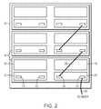
- FIG. 2is a rear view of the rack mount system and storage enclosures of FIG. 1 ;
- FIGS. 3-4are block diagrams of components of the rack mount system and storage enclosures of FIG. 1 that may be used in connection with techniques herein;
- FIG. 5is a diagram illustrating in more detail components that may be used in connection with techniques herein;
- FIG. 6is an example illustrating storage device layout
- FIG. 7is a diagram illustrating a drive state bitmap
- FIG. 8is a diagram illustrating sequence of events that may be used in connection with techniques herein.
- FIGS. 9-10are flow diagrams illustrating processes that may be used in connection with techniques herein.
- a methodmay be provided for detecting an alternate path, particularly a better path, in a storage system in order to continue servicing user IOs in case of a problem accessing one or more disk drives in a RAID group.
- a disk drivewhen a physical disk drive fails (“failed drive”), a host attached to the data storage system keeps writing data to the physical disk drive.
- failed driveWhen the failed drive is replaced, either automatically (e.g., by a hot spare, which is an idle disk drive that can be integrated into the RAID group electronically) or manually (by removing the failed drive and inserting a new drive), a disk rebuild is needed wherein the failed drive's data is rebuilt onto the replacement drive based on data storage redundancy within the RAID group.
- the disk rebuildcan take a very long time, especially in the case of a disk drive containing a large amount of data.
- all the disk drives within the RAID groupare hit with heavy IOs. Heavy IOs cause significant IO performance degradation for hosts that are attached to a data storage system. As a result, in a conventional system, it may also cause data unavailability for host applications that cannot tolerate long response times.
- removing a set of disk drives only when there is no alternate path (or no suitable alternate path) availableallows the data storage system to be more efficient and can help avoid unnecessary rebuilds of disk drives.
- determining the alternate path to a set of disk drives to continue servicing user IOsprovides uninterrupted access to data and improves system's performance dramatically.
- use of determining alternate paths in a faulted systemcan provide one or more of the following advantages: improving data storage system performance by avoiding rebuilding a set of disk drives when access to those disk drives is restored, increasing system availability by determining an alternate path to a set of disk drives when a storage processor loses access to the set of disk drives and eliminating degraded IO performance during read or write operations when a problem occurs on a single storage processor.
- a rack mount cabinet 12includes several storage enclosures 14 .
- Each storage enclosure 14includes several disk drives 16 .
- the disk drives and the enclosuresare preferably interconnected via a serial bus loop or ring architecture, e.g., Fibre Channel Arbitrated Loop (FC-AL).
- FC-ALFibre Channel Arbitrated Loop
- FIG. 2there is shown a rear view of the rack mount cabinet 12 and the storage enclosure 14 .
- Each storage enclosureincludes two power supplies 18 , and two LCCs 20 .
- the power supplies 18 and link control cards 20are coupled to the disk drives 16 via a midplane within the chassis (not shown in FIG. 2 ).
- the link control card 20serves to interconnect the disks and enclosures on the communication loop FC-AL.
- Each link control card 20includes a primary port 22 and an expansion port 24 . These ports are used to link the storage enclosures together on a single communication loop FC-AL.
- a cable 26may come from a host or from another storage system, and plugs into the primary port 22 .
- the communication loop FC-ALextends from the primary port 22 , is coupled to the disk drives 16 , and continues out the expansion port 24 .
- a cable 28couples the expansion port 24 of a first storage enclosure 14 to the primary port 22 of a second storage enclosure 14 . All the storage enclosures 14 are interconnected in this manner in a daisy chain to form the communication loop FC-AL. Thus, all the disk drives 16 are interconnected on the same communication loop FC-AL.
- Each link control card 20is capable of controlling all the disks 16 in a given enclosure.
- FIG. 3illustrates communication among drives 16 , midplane 30 , LCCA and LCCB 20 , and storage processors (“SPs”) 80 .
- storage processors 80are controllers within the storage system that control the storage system's access to the storage enclosure, and are configured to communicate with each of drives 16 (exemplified by drive 0 in FIG. 3 ) over respective Fibre Channel links (loops) 74 , 70 , and over respective diplexing links 76 , 72 as described in U.S. Pat. No. 5,901,151 to Bleiweiss, et al. entitled “System for orthogonal signal multiplexing”, which is hereby incorporated herein by reference in its entirety.
- FIG. 4illustrates an example implementation of data storage system 10 having enclosures 14 (specifically 14 X, 14 Y) in communication with SPs 80 (specifically 80 A, 80 B) using communication loops FC-AL 74 , 70 .
- SPs 80 A, 80 Bmay or may not be included in one of enclosures 14 X, 14 Y.
- Enclosure 14 Xhas LCCs 20 AX, 20 BX and disks 16 X- 0 through 16 X- 14
- enclosure 14 Yhas LCCs 20 AY, 20 BY and disks 16 Y- 0 through 16 Y- 14 .
- Loop 74allows SP 80 A to communicate with disks 16 X- 0 through 16 X- 14 via LCC 20 AX, and with disks 16 Y- 0 through 16 Y- 14 via LCC 20 AY.
- Loop 70allows SP 80 B to communicate with disks 16 X- 0 through 16 X- 14 via LCC 20 BX, and with disks 16 Y- 0 through 16 Y- 14 via LCC 20 BY.
- Each of disks 16 X- 0 through 16 X- 14 and 16 Y- 0 through 16 Y- 14has a FC receiver and a FC transmitter for each loop connection.
- disk 16 X- 0has receiver 102 and transmitter 104 .
- a communication directed from SP 80 A to disk 16 Y- 14is first received at disk 16 X- 0 by receiver 102 and is transmitted by transmitter 104 to disk 16 X- 1 , which in turn passes the communication along to disk 16 X- 2 , and so on.
- the communicationpasses between enclosures when disk 16 X- 14 passes it to disk 16 Y- 0 , which in turn passes it to disk 16 Y- 1 , and so on.
- the communicationreaches its destination, disk 16 Y- 14 .
- a communication directed from disk 16 Y- 14 to SP 80 Atravels directly to SP 80 A since there are no disks between disk 16 Y- 14 and SP 80 A in that direction on the loop.
- one or more disks or enclosuresmay be set, e.g., using the diplex signals, to a bypass mode such that FC signals travel along the loop as if the disks or enclosures were not on the loop.
- a communication directed from disk 16 X- 14 to SP 80 Atravels directly to SP 80 A since there are no disks between disk 16 X- 14 and SP 80 A in that direction on the loop when enclosure 14 Y is not on the loop.
- a communication directed from SP 80 A to disk 16 X- 4passes directly from disk 16 X- 1 to disk 16 X- 3 on its way to disk 16 X- 4 .
- a storage processorprovides communications between host system 90 and disk drives 16 .
- Data storage system 10includes at least two storage processors 96 , 94 .
- Storage Processor (SPA) 96accesses the disk drives 16 using Fibre Channel communication loop FC-AL 74 and storage processor (SPB) 94 accesses the disk drives 16 using Fibre Channel communication loop FC-AL 70 .
- SPAStorage Processor
- SPBstorage processor
- Host system 90may not address the disk drives of the storage systems directly, but rather access to data may be provided to one or more host systems from what the host systems view as a plurality of logical devices or logical volumes (“LVs” or “LUNs”).
- Host system 90sends a request to hostside logic (“hostside”) (e.g., hostside 92 ) to access data stored on logical devices.
- the hostsidesends appropriate status back to the host system in case access to data fails.
- the LVsmay or may not correspond to the physical disk drives.
- one or more LVsmay reside on a single physical disk drive. Data in a single data storage system may be accessed by multiple hosts allowing the hosts to share the data residing therein.
- the host or host networkis sometimes referred to as the front end and from disk adapters toward the disks is sometimes referred to as the back end.
- a disk adapteris a component that allows disk drives to communicate with a storage processor.
- FIG. 6illustrates one of the many ways data can be stored on the disk drives 16 .
- RAID Group 115may be formed from physical devices 16 .
- the data storage system 10best practices of a policy may specify the particular RAID level and configuration for the type of storage extent being formed.
- the RAID Group 115may provide a number of data storage LUNs 111 .
- An embodimentmay also utilize one or more additional logical device layers on top of the LUNs 111 to form one or more logical device volumes 113 .
- the particular additional logical device layers used, if any,may vary with the data storage system. It should be noted that there may not be a 1-1 correspondence between the LUNs of 111 and the volumes of 113 .
- device volumes 113may be formed or configured from physical devices 16 .
- Device volumes 113 , LUNs 111 and physical devices 16may be configured to store one or more blocks of data or one or more files organized as a file system.
- one storage processor(“primary SP”) is primarily responsible for all communications with a set of disk drives in a data storage system, and one or more other SPs may be primarily responsible for all communications with other sets of disk drives in the data storage system.
- a back end path failureoccurs when a problem in any of components that make up the back end causes a set of disk drives to be inaccessible on a primary SP in a data storage system but accessible on another SP in the data storage system.
- a back end path failureis generally caused by a faulty fibre channel cable, a link control card or a single disk port failure in a disk with two ports.
- a trespass commandis issued to the other SP that transfers the responsibility of communication with the affected disk drives to the other SP, in effect causing the other SP to become the new primary SP for the affected disk drives.
- an alternate pathe.g., the most efficient alternate path
- host 90sends an IO request through hostside 92 to storage processor SPA 96 .
- SPA 96sends corresponding data requests to disk drives 16 through upper redirector 98 , lower redirector 100 , configuration manager (“CM”) 102 and drive handler 104 .
- CMconfiguration manager
- Upper redirector 98 and lower redirector 100enable the data storage system to provide an alternate path to a set of disk drives by redirecting I/Os from one SP to another SP.
- Drive handler 104enables the data storage system to interact with disk drives 16 .
- Configuration manager 102communicates with other storage processors in the data storage system in order to enable the data storage system to determine an alternate path to a set of disk drives.
- Configuration manager 102detects a back end path failure where communication loop FC-AL A 74 cannot access LUNs on a set of disk drives in a RAID group. It should be noted that detection of the back end path failure may happen at any of different places within a storage processor.
- configuration manager 102may detect a back end failure when SPA 96 accesses data from a set of disk drives 16 .
- Lower redirector 100then may receive a status report from configuration manager 102 indicating that a LUN is missing disks due to a back end path failure.
- Lower redirector 100broadcasts the status report to other storage processors in the data storage system 10 , in this case to lower redirector 108 of SPB 94 (also referred as peer SP).
- the SPB 94compares the status report with SPB's own local data.
- the data storage systemcauses SPA 96 to send a trespass command to SPB 94 that pulls ownership of the affected LUNs from SPA 96 to SPBB 94 .
- the trespass commandchanges responsibility of communication with the set of disk drive in RAID group from SPA 96 to SPB 94 , in effect, by changing the ownership of one or more LUNs associated with the set of disk drives.
- Storage Processor SPB 94then services those IOs by sending the IO requests to disk drives 16 through upper redirector 106 , lower redirector 108 , configuration manager 110 , drive handler 112 and communication loop FC-AL B 70 .
- Lower redirectors 100 and 108may also handle rejected read/write IOs that were rejected because a set of disk drives are inaccessible due to a back end path failure on SPA 96 or SPB 94 .
- IOs targeted for the set of disk drivesmay also be redirected to the peer SP (e.g., I/Os from SPA 96 may be redirected to SPB 94 in case of failure on SPA 96 and I/Os from SPB 94 may be redirected to SPA 96 in case of failure on SPB 94 ) and those redirected I/Os could also fail due to any number of reasons on the peer SP. In that case, lower redirectors 100 and 108 retries the failed IOs on their respective local SPs again.
- Configuration manager 102sends a request to disk drive 16 that determines whether there are any write-a-side IOs pending. Configuration manager 102 then decides whether to transfer the ownership of the affected LUNs to another SP that has a better path to the disk drives 16 . Once back end problems are fixed and SPA 96 regains access to the disk drives through communication loop FC-AL A 74 , ownership of all the affected LUNs returns to SPA 96 , in turns, avoiding the need to rebuild the set of disk drives.
- Drive state bitmap 170stores the status of a set of disk drives in a RAID group.
- Each storage processormaintains a bitmap indicating their local status of disk drive access. For example, for a set of disk drives D 1 -Dn in a RAID group, D 1 171 indicates whether access to disk D 1 is operational and working, D 2 172 indicates status for drive D 2 , D 3 174 indicates status for drive D 3 , D 4 176 indicates status for drive D 4 and Dn 178 indicates status for drive Dn.
- FIG. 8shown is a diagram illustrating a method of back end path failure handling by determining an alternate path in case of a disk drive access failure on a single storage processor.
- local SPSPA 96
- detects a drive problem when the local SP cannot access a drive due to one or more back end problemsstep 116 .
- SPA 96sends a message to peer SP (SPB 94 , for example) along with its own local drive state bitmap A (step 118 ).
- peer SPpeer SP
- the peer SPreplies back with the peer SP's own drive state bitmap B, and saves the bitmap A received from SPA (step 120 ).
- Once SPA 96 receives the reply from SPB 94it uses the local drive state bitmap A and peer drive state bitmap B, to determine whether a peer SP has better path to the drive on which SPA detected a back end problem (step 122 ).
- a local drive of a storage processoris a drive that primarily communicates with that storage processor and the storage processor has ownership of one or more LUNs associated with that local drive. Also, each storage processor in the data storage system maintains a local drive state bitmap that includes information regarding a set of disk drives with which each storage processor primarily communicates. There may be different failure scenarios where back end path failure handling determines the alternate path in a faulted system. Some of the failure scenarios are illustrated below. First is a single drive failure on both storage processors. In this case, SPB also sends the same request to SPA requesting information on disk drive status for all the disks within a RAID group. Because configuration manager runs independently on each SP, there may be some timing differences as to when the SPs are able to detect a local drive problem.
- Both SPs in this caseget the local drive state bitmap of the other SP and start drive rebuild processing.
- LUNs associated with the disk drivewill become degraded.
- a LUNgoes into a degraded mode when I/Os directed to that LUN start failing.
- Lower redirectorwill then be notified that the LU is degraded and missing disks.
- Second caseis when a local SP looses access to one drive and a peer SP looses access to another drive.
- the local SPdetects problem accessing a drive, it sends a status to its lower redirector indicating that a set of LUNs on that disk drive are in inaccessible state and the SP can not service IO without going into degraded mode.
- the lower redirector of the local SPgets the status and broadcasts it to the peer SP.
- the peer SPdetermines that it has a better path and pulls the ownership of the set of LUN on the disk drive over to itself by causing a trespass command to be executed. Later the peer SP detects a problem accessing another drive. Because the peer SP is already aware of disk access problem on the local SP, it kicks off drive rebuild processing for the drive. If the same drive fails on both SPs, then the data storage system will go into degraded operations for the affected volumes (LUNs) with ownership on the last SP for which explicit ownership was established. If access to different drives fail on both SPs, then the SP for which explicit ownership was last established will assume ownership of the given volume(s) with degraded operations.
- determining alternate pathsstarts with a storage processor in a data storage system 10 detecting lost access to a set of one or more disk drives in a RAID group (step 200 ).
- the storage processorthen proceeds to determine an alternate path in order to continue servicing user I/Os from a host system 90 by finding a better path to access the set of one or more disk drives (step 205 ).
- the storage processorrelinquishes ownership of a set of one or more LUNs associated with the set of disk drives in the RAID group (step 210 ).
- An alternate storage processor having the better pathis assigned ownership of the set of one or more LUNs and I/Os from the host system 90 are redirected to that storage processor (step 215 ). Once access to the set of one or more disk drives is restored, the original storage processor regains ownership of the set of one or more LUNs from the alternate storage processor (step 220 ).
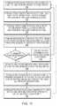
- FIG. 10shown is a flow diagram illustrating in detail the method of determining an alternate path on detecting a back end problem in a data storage system.
- a storage processordetects a back end failure while accessing a set of one or more disk drives in a RAID group (step 250 )
- the storage processorsends requests to all other storage processors in a data storage system 10 for information on their respective local drive state bitmap 170 (step 255 ).
- the storage processorUpon receiving the information from all the other storage processors (step 260 ), the storage processor compares its local drive state bitmap with information received from other storage processors in order to determine, if possible, an alternate path to the set of disk drives in the RAID group (step 265 ). If no alternate path is determined (step 270 ), an error is returned back to a host system 90 and system continues servicing IO in degraded mode (step 275 ). Upon finding an alternate path, the storage processor relinquishes ownership of a set of one or more LUNs associated with the set of disk drives in the RAID group (step 280 ).
- An alternate storage processor having the alternate pathis assigned ownership of the set of one or more LUNs and I/Os from the host system 90 are redirected to that storage processor (step 285 ). Once access to the set of one or more disk drives is restored, the original storage processor regains ownership of the set of one or more LUNS from the alternate storage processor (step 290 ). Additionally, when a request is received from a peer SP to handle a back end failure, a few sanity checks are performed to ensure that an alternate path can be determined. Some of the sanity checks are as follows: determination of whether a write cache is enabled, determination of whether a write cache of a peer SP is enabled and determination of whether a write cache of a disk drive is enabled.
Landscapes
- Engineering & Computer Science (AREA)
- Theoretical Computer Science (AREA)
- Quality & Reliability (AREA)
- Physics & Mathematics (AREA)
- General Engineering & Computer Science (AREA)
- General Physics & Mathematics (AREA)
- Debugging And Monitoring (AREA)
Abstract
Description
Claims (18)
Priority Applications (1)
| Application Number | Priority Date | Filing Date | Title |
|---|---|---|---|
| US12/892,333US8381027B1 (en) | 2010-09-28 | 2010-09-28 | Determining alternate paths in faulted systems |
Applications Claiming Priority (1)
| Application Number | Priority Date | Filing Date | Title |
|---|---|---|---|
| US12/892,333US8381027B1 (en) | 2010-09-28 | 2010-09-28 | Determining alternate paths in faulted systems |
Publications (1)
| Publication Number | Publication Date |
|---|---|
| US8381027B1true US8381027B1 (en) | 2013-02-19 |
Family
ID=47682969
Family Applications (1)
| Application Number | Title | Priority Date | Filing Date |
|---|---|---|---|
| US12/892,333ActiveUS8381027B1 (en) | 2010-09-28 | 2010-09-28 | Determining alternate paths in faulted systems |
Country Status (1)
| Country | Link |
|---|---|
| US (1) | US8381027B1 (en) |
Cited By (6)
| Publication number | Priority date | Publication date | Assignee | Title |
|---|---|---|---|---|
| US20130166953A1 (en)* | 2010-09-01 | 2013-06-27 | Fujitsu Limited | System and method of processing failure |
| US20130311719A1 (en)* | 2012-05-18 | 2013-11-21 | Atto Technology, Inc. | Target path selection for storage controllers |
| US8954808B1 (en)* | 2010-11-30 | 2015-02-10 | Symantec Corporation | Systems and methods for performing input/output path failovers |
| US20150100821A1 (en)* | 2013-10-09 | 2015-04-09 | Fujitsu Limited | Storage control apparatus, storage control system, and storage control method |
| US20150347251A1 (en)* | 2014-05-28 | 2015-12-03 | International Business Machines Corporation | Recovery mechanisms across storage nodes that reduce the impact on host input and output operations |
| US9645872B1 (en)* | 2015-03-27 | 2017-05-09 | EMC IP Holding Company LLC | Method to use multipath to reduce IO error handle duration |
Citations (8)
| Publication number | Priority date | Publication date | Assignee | Title |
|---|---|---|---|---|
| US5975738A (en)* | 1997-09-30 | 1999-11-02 | Lsi Logic Corporation | Method for detecting failure in redundant controllers using a private LUN |
| US20020133735A1 (en)* | 2001-01-16 | 2002-09-19 | International Business Machines Corporation | System and method for efficient failover/failback techniques for fault-tolerant data storage system |
| US6578158B1 (en)* | 1999-10-28 | 2003-06-10 | International Business Machines Corporation | Method and apparatus for providing a raid controller having transparent failover and failback |
| US20030140191A1 (en)* | 2002-01-24 | 2003-07-24 | Mcgowen Michael E. | System, method, and computer program product for on-line replacement of a host bus adapter |
| US6874100B2 (en)* | 2001-07-12 | 2005-03-29 | Digi-Data Corporation | Raid system with multiple controllers and proof against any single point of failure |
| US20050147932A1 (en)* | 2003-12-31 | 2005-07-07 | Eastman Kodak Company | Method for processing color motion picture print film |
| US7318138B1 (en)* | 2005-08-30 | 2008-01-08 | Symantec Operating Corporation | Preventing undesired trespass in storage arrays |
| US20090265584A1 (en)* | 2006-04-11 | 2009-10-22 | Hitachi, Ltd. | Storage control unit with control signal path between coupled controllers |
- 2010
- 2010-09-28USUS12/892,333patent/US8381027B1/enactiveActive
Patent Citations (8)
| Publication number | Priority date | Publication date | Assignee | Title |
|---|---|---|---|---|
| US5975738A (en)* | 1997-09-30 | 1999-11-02 | Lsi Logic Corporation | Method for detecting failure in redundant controllers using a private LUN |
| US6578158B1 (en)* | 1999-10-28 | 2003-06-10 | International Business Machines Corporation | Method and apparatus for providing a raid controller having transparent failover and failback |
| US20020133735A1 (en)* | 2001-01-16 | 2002-09-19 | International Business Machines Corporation | System and method for efficient failover/failback techniques for fault-tolerant data storage system |
| US6874100B2 (en)* | 2001-07-12 | 2005-03-29 | Digi-Data Corporation | Raid system with multiple controllers and proof against any single point of failure |
| US20030140191A1 (en)* | 2002-01-24 | 2003-07-24 | Mcgowen Michael E. | System, method, and computer program product for on-line replacement of a host bus adapter |
| US20050147932A1 (en)* | 2003-12-31 | 2005-07-07 | Eastman Kodak Company | Method for processing color motion picture print film |
| US7318138B1 (en)* | 2005-08-30 | 2008-01-08 | Symantec Operating Corporation | Preventing undesired trespass in storage arrays |
| US20090265584A1 (en)* | 2006-04-11 | 2009-10-22 | Hitachi, Ltd. | Storage control unit with control signal path between coupled controllers |
Cited By (13)
| Publication number | Priority date | Publication date | Assignee | Title |
|---|---|---|---|---|
| US8832501B2 (en)* | 2010-09-01 | 2014-09-09 | Fujitsu Limited | System and method of processing failure |
| US20130166953A1 (en)* | 2010-09-01 | 2013-06-27 | Fujitsu Limited | System and method of processing failure |
| US8954808B1 (en)* | 2010-11-30 | 2015-02-10 | Symantec Corporation | Systems and methods for performing input/output path failovers |
| US20130311719A1 (en)* | 2012-05-18 | 2013-11-21 | Atto Technology, Inc. | Target path selection for storage controllers |
| US11474704B2 (en)* | 2012-05-18 | 2022-10-18 | Atto Technology, Inc. | Target path selection for storage controllers |
| US9542273B2 (en)* | 2013-10-09 | 2017-01-10 | Fujitsu Limited | Storage control apparatus, storage control system, and storage control method for failure detection and configuration of cascaded storage cabinets |
| US20150100821A1 (en)* | 2013-10-09 | 2015-04-09 | Fujitsu Limited | Storage control apparatus, storage control system, and storage control method |
| US9459974B2 (en)* | 2014-05-28 | 2016-10-04 | International Business Machines Corporation | Recovery mechanisms across storage nodes that reduce the impact on host input and output operations |
| US10067818B2 (en) | 2014-05-28 | 2018-09-04 | International Business Machines Corporation | Recovery mechanisms across storage nodes that reduce the impact on host input and output operations |
| US10664341B2 (en) | 2014-05-28 | 2020-05-26 | International Business Machines Corporation | Recovery mechanisms across storage nodes that reduce the impact on host input and output operations |
| US10671475B2 (en) | 2014-05-28 | 2020-06-02 | International Business Machines Corporation | Recovery mechanisms across storage nodes that reduce the impact on host input and output operations |
| US20150347251A1 (en)* | 2014-05-28 | 2015-12-03 | International Business Machines Corporation | Recovery mechanisms across storage nodes that reduce the impact on host input and output operations |
| US9645872B1 (en)* | 2015-03-27 | 2017-05-09 | EMC IP Holding Company LLC | Method to use multipath to reduce IO error handle duration |
Similar Documents
| Publication | Publication Date | Title |
|---|---|---|
| US8423818B2 (en) | Disk array apparatus and method for controlling the same | |
| US10191669B2 (en) | Redundant SAS storage virtualization subsystem and system using the same and method therefor | |
| US8074105B2 (en) | High data availability SAS-based RAID system | |
| US9697087B2 (en) | Storage controller to perform rebuilding while copying, and storage system, and control method thereof | |
| US7111084B2 (en) | Data storage network with host transparent failover controlled by host bus adapter | |
| US8301810B2 (en) | SAS storage virtualization controller, subsystem and system using the same, and method therefor | |
| US8683260B1 (en) | Managing ownership of logical volumes | |
| US7133967B2 (en) | Storage system, controller, control method and program product therefor | |
| US8756454B2 (en) | Method, apparatus, and system for a redundant and fault tolerant solid state disk | |
| US7313721B2 (en) | Apparatus and method for performing a preemptive reconstruct of a fault-tolerant RAID array | |
| JP5087249B2 (en) | Storage system and storage system control method | |
| US6578158B1 (en) | Method and apparatus for providing a raid controller having transparent failover and failback | |
| US8402189B2 (en) | Information processing apparatus and data transfer method | |
| US7146448B2 (en) | Apparatus and method for adopting an orphan I/O port in a redundant storage controller | |
| US20150032928A1 (en) | Optimized redundant high availability sas topology | |
| US8381027B1 (en) | Determining alternate paths in faulted systems | |
| JP2007200299A (en) | Apparatus and method to reconfigure storage array disposed in data storage system | |
| US7650463B2 (en) | System and method for RAID recovery arbitration in shared disk applications | |
| US8782465B1 (en) | Managing drive problems in data storage systems by tracking overall retry time | |
| US8161316B1 (en) | Managing loop interface instability | |
| US7752340B1 (en) | Atomic command retry in a data storage system | |
| US7506201B2 (en) | System and method of repair management for RAID arrays | |
| US20070050544A1 (en) | System and method for storage rebuild management | |
| US11809268B1 (en) | Discovering host-switch link and ISL issues from the storage array | |
| US7715378B1 (en) | Error notification and forced retry in a data storage system |
Legal Events
| Date | Code | Title | Description |
|---|---|---|---|
| AS | Assignment | Owner name:EMC CORPORATION, MASSACHUSETTS Free format text:ASSIGNMENT OF ASSIGNORS INTEREST;ASSIGNORS:LIU, QING;ZHANG, QI;TOLVANEN, PETER;AND OTHERS;SIGNING DATES FROM 20100924 TO 20100927;REEL/FRAME:025862/0521 | |
| STCF | Information on status: patent grant | Free format text:PATENTED CASE | |
| FPAY | Fee payment | Year of fee payment:4 | |
| AS | Assignment | Owner name:CREDIT SUISSE AG, CAYMAN ISLANDS BRANCH, AS COLLATERAL AGENT, NORTH CAROLINA Free format text:SECURITY AGREEMENT;ASSIGNORS:ASAP SOFTWARE EXPRESS, INC.;AVENTAIL LLC;CREDANT TECHNOLOGIES, INC.;AND OTHERS;REEL/FRAME:040134/0001 Effective date:20160907 Owner name:THE BANK OF NEW YORK MELLON TRUST COMPANY, N.A., AS NOTES COLLATERAL AGENT, TEXAS Free format text:SECURITY AGREEMENT;ASSIGNORS:ASAP SOFTWARE EXPRESS, INC.;AVENTAIL LLC;CREDANT TECHNOLOGIES, INC.;AND OTHERS;REEL/FRAME:040136/0001 Effective date:20160907 Owner name:CREDIT SUISSE AG, CAYMAN ISLANDS BRANCH, AS COLLAT Free format text:SECURITY AGREEMENT;ASSIGNORS:ASAP SOFTWARE EXPRESS, INC.;AVENTAIL LLC;CREDANT TECHNOLOGIES, INC.;AND OTHERS;REEL/FRAME:040134/0001 Effective date:20160907 Owner name:THE BANK OF NEW YORK MELLON TRUST COMPANY, N.A., A Free format text:SECURITY AGREEMENT;ASSIGNORS:ASAP SOFTWARE EXPRESS, INC.;AVENTAIL LLC;CREDANT TECHNOLOGIES, INC.;AND OTHERS;REEL/FRAME:040136/0001 Effective date:20160907 | |
| AS | Assignment | Owner name:EMC IP HOLDING COMPANY LLC, MASSACHUSETTS Free format text:ASSIGNMENT OF ASSIGNORS INTEREST;ASSIGNOR:EMC CORPORATION;REEL/FRAME:040203/0001 Effective date:20160906 | |
| AS | Assignment | Owner name:THE BANK OF NEW YORK MELLON TRUST COMPANY, N.A., T Free format text:SECURITY AGREEMENT;ASSIGNORS:CREDANT TECHNOLOGIES, INC.;DELL INTERNATIONAL L.L.C.;DELL MARKETING L.P.;AND OTHERS;REEL/FRAME:049452/0223 Effective date:20190320 Owner name:THE BANK OF NEW YORK MELLON TRUST COMPANY, N.A., TEXAS Free format text:SECURITY AGREEMENT;ASSIGNORS:CREDANT TECHNOLOGIES, INC.;DELL INTERNATIONAL L.L.C.;DELL MARKETING L.P.;AND OTHERS;REEL/FRAME:049452/0223 Effective date:20190320 | |
| AS | Assignment | Owner name:THE BANK OF NEW YORK MELLON TRUST COMPANY, N.A., TEXAS Free format text:SECURITY AGREEMENT;ASSIGNORS:CREDANT TECHNOLOGIES INC.;DELL INTERNATIONAL L.L.C.;DELL MARKETING L.P.;AND OTHERS;REEL/FRAME:053546/0001 Effective date:20200409 | |
| MAFP | Maintenance fee payment | Free format text:PAYMENT OF MAINTENANCE FEE, 8TH YEAR, LARGE ENTITY (ORIGINAL EVENT CODE: M1552); ENTITY STATUS OF PATENT OWNER: LARGE ENTITY Year of fee payment:8 | |
| AS | Assignment | Owner name:WYSE TECHNOLOGY L.L.C., CALIFORNIA Free format text:RELEASE BY SECURED PARTY;ASSIGNOR:CREDIT SUISSE AG, CAYMAN ISLANDS BRANCH;REEL/FRAME:058216/0001 Effective date:20211101 Owner name:SCALEIO LLC, MASSACHUSETTS Free format text:RELEASE BY SECURED PARTY;ASSIGNOR:CREDIT SUISSE AG, CAYMAN ISLANDS BRANCH;REEL/FRAME:058216/0001 Effective date:20211101 Owner name:MOZY, INC., WASHINGTON Free format text:RELEASE BY SECURED PARTY;ASSIGNOR:CREDIT SUISSE AG, CAYMAN ISLANDS BRANCH;REEL/FRAME:058216/0001 Effective date:20211101 Owner name:MAGINATICS LLC, CALIFORNIA Free format text:RELEASE BY SECURED PARTY;ASSIGNOR:CREDIT SUISSE AG, CAYMAN ISLANDS BRANCH;REEL/FRAME:058216/0001 Effective date:20211101 Owner name:FORCE10 NETWORKS, INC., CALIFORNIA Free format text:RELEASE BY SECURED PARTY;ASSIGNOR:CREDIT SUISSE AG, CAYMAN ISLANDS BRANCH;REEL/FRAME:058216/0001 Effective date:20211101 Owner name:EMC IP HOLDING COMPANY LLC, TEXAS Free format text:RELEASE BY SECURED PARTY;ASSIGNOR:CREDIT SUISSE AG, CAYMAN ISLANDS BRANCH;REEL/FRAME:058216/0001 Effective date:20211101 Owner name:EMC CORPORATION, MASSACHUSETTS Free format text:RELEASE BY SECURED PARTY;ASSIGNOR:CREDIT SUISSE AG, CAYMAN ISLANDS BRANCH;REEL/FRAME:058216/0001 Effective date:20211101 Owner name:DELL SYSTEMS CORPORATION, TEXAS Free format text:RELEASE BY SECURED PARTY;ASSIGNOR:CREDIT SUISSE AG, CAYMAN ISLANDS BRANCH;REEL/FRAME:058216/0001 Effective date:20211101 Owner name:DELL SOFTWARE INC., CALIFORNIA Free format text:RELEASE BY SECURED PARTY;ASSIGNOR:CREDIT SUISSE AG, CAYMAN ISLANDS BRANCH;REEL/FRAME:058216/0001 Effective date:20211101 Owner name:DELL PRODUCTS L.P., TEXAS Free format text:RELEASE BY SECURED PARTY;ASSIGNOR:CREDIT SUISSE AG, CAYMAN ISLANDS BRANCH;REEL/FRAME:058216/0001 Effective date:20211101 Owner name:DELL MARKETING L.P., TEXAS Free format text:RELEASE BY SECURED PARTY;ASSIGNOR:CREDIT SUISSE AG, CAYMAN ISLANDS BRANCH;REEL/FRAME:058216/0001 Effective date:20211101 Owner name:DELL INTERNATIONAL, L.L.C., TEXAS Free format text:RELEASE BY SECURED PARTY;ASSIGNOR:CREDIT SUISSE AG, CAYMAN ISLANDS BRANCH;REEL/FRAME:058216/0001 Effective date:20211101 Owner name:DELL USA L.P., TEXAS Free format text:RELEASE BY SECURED PARTY;ASSIGNOR:CREDIT SUISSE AG, CAYMAN ISLANDS BRANCH;REEL/FRAME:058216/0001 Effective date:20211101 Owner name:CREDANT TECHNOLOGIES, INC., TEXAS Free format text:RELEASE BY SECURED PARTY;ASSIGNOR:CREDIT SUISSE AG, CAYMAN ISLANDS BRANCH;REEL/FRAME:058216/0001 Effective date:20211101 Owner name:AVENTAIL LLC, CALIFORNIA Free format text:RELEASE BY SECURED PARTY;ASSIGNOR:CREDIT SUISSE AG, CAYMAN ISLANDS BRANCH;REEL/FRAME:058216/0001 Effective date:20211101 Owner name:ASAP SOFTWARE EXPRESS, INC., ILLINOIS Free format text:RELEASE BY SECURED PARTY;ASSIGNOR:CREDIT SUISSE AG, CAYMAN ISLANDS BRANCH;REEL/FRAME:058216/0001 Effective date:20211101 | |
| AS | Assignment | Owner name:SCALEIO LLC, MASSACHUSETTS Free format text:RELEASE OF SECURITY INTEREST IN PATENTS PREVIOUSLY RECORDED AT REEL/FRAME (040136/0001);ASSIGNOR:THE BANK OF NEW YORK MELLON TRUST COMPANY, N.A., AS NOTES COLLATERAL AGENT;REEL/FRAME:061324/0001 Effective date:20220329 Owner name:EMC IP HOLDING COMPANY LLC (ON BEHALF OF ITSELF AND AS SUCCESSOR-IN-INTEREST TO MOZY, INC.), TEXAS Free format text:RELEASE OF SECURITY INTEREST IN PATENTS PREVIOUSLY RECORDED AT REEL/FRAME (040136/0001);ASSIGNOR:THE BANK OF NEW YORK MELLON TRUST COMPANY, N.A., AS NOTES COLLATERAL AGENT;REEL/FRAME:061324/0001 Effective date:20220329 Owner name:EMC CORPORATION (ON BEHALF OF ITSELF AND AS SUCCESSOR-IN-INTEREST TO MAGINATICS LLC), MASSACHUSETTS Free format text:RELEASE OF SECURITY INTEREST IN PATENTS PREVIOUSLY RECORDED AT REEL/FRAME (040136/0001);ASSIGNOR:THE BANK OF NEW YORK MELLON TRUST COMPANY, N.A., AS NOTES COLLATERAL AGENT;REEL/FRAME:061324/0001 Effective date:20220329 Owner name:DELL MARKETING CORPORATION (SUCCESSOR-IN-INTEREST TO FORCE10 NETWORKS, INC. AND WYSE TECHNOLOGY L.L.C.), TEXAS Free format text:RELEASE OF SECURITY INTEREST IN PATENTS PREVIOUSLY RECORDED AT REEL/FRAME (040136/0001);ASSIGNOR:THE BANK OF NEW YORK MELLON TRUST COMPANY, N.A., AS NOTES COLLATERAL AGENT;REEL/FRAME:061324/0001 Effective date:20220329 Owner name:DELL PRODUCTS L.P., TEXAS Free format text:RELEASE OF SECURITY INTEREST IN PATENTS PREVIOUSLY RECORDED AT REEL/FRAME (040136/0001);ASSIGNOR:THE BANK OF NEW YORK MELLON TRUST COMPANY, N.A., AS NOTES COLLATERAL AGENT;REEL/FRAME:061324/0001 Effective date:20220329 Owner name:DELL INTERNATIONAL L.L.C., TEXAS Free format text:RELEASE OF SECURITY INTEREST IN PATENTS PREVIOUSLY RECORDED AT REEL/FRAME (040136/0001);ASSIGNOR:THE BANK OF NEW YORK MELLON TRUST COMPANY, N.A., AS NOTES COLLATERAL AGENT;REEL/FRAME:061324/0001 Effective date:20220329 Owner name:DELL USA L.P., TEXAS Free format text:RELEASE OF SECURITY INTEREST IN PATENTS PREVIOUSLY RECORDED AT REEL/FRAME (040136/0001);ASSIGNOR:THE BANK OF NEW YORK MELLON TRUST COMPANY, N.A., AS NOTES COLLATERAL AGENT;REEL/FRAME:061324/0001 Effective date:20220329 Owner name:DELL MARKETING L.P. (ON BEHALF OF ITSELF AND AS SUCCESSOR-IN-INTEREST TO CREDANT TECHNOLOGIES, INC.), TEXAS Free format text:RELEASE OF SECURITY INTEREST IN PATENTS PREVIOUSLY RECORDED AT REEL/FRAME (040136/0001);ASSIGNOR:THE BANK OF NEW YORK MELLON TRUST COMPANY, N.A., AS NOTES COLLATERAL AGENT;REEL/FRAME:061324/0001 Effective date:20220329 Owner name:DELL MARKETING CORPORATION (SUCCESSOR-IN-INTEREST TO ASAP SOFTWARE EXPRESS, INC.), TEXAS Free format text:RELEASE OF SECURITY INTEREST IN PATENTS PREVIOUSLY RECORDED AT REEL/FRAME (040136/0001);ASSIGNOR:THE BANK OF NEW YORK MELLON TRUST COMPANY, N.A., AS NOTES COLLATERAL AGENT;REEL/FRAME:061324/0001 Effective date:20220329 | |
| AS | Assignment | Owner name:SCALEIO LLC, MASSACHUSETTS Free format text:RELEASE OF SECURITY INTEREST IN PATENTS PREVIOUSLY RECORDED AT REEL/FRAME (045455/0001);ASSIGNOR:THE BANK OF NEW YORK MELLON TRUST COMPANY, N.A., AS NOTES COLLATERAL AGENT;REEL/FRAME:061753/0001 Effective date:20220329 Owner name:EMC IP HOLDING COMPANY LLC (ON BEHALF OF ITSELF AND AS SUCCESSOR-IN-INTEREST TO MOZY, INC.), TEXAS Free format text:RELEASE OF SECURITY INTEREST IN PATENTS PREVIOUSLY RECORDED AT REEL/FRAME (045455/0001);ASSIGNOR:THE BANK OF NEW YORK MELLON TRUST COMPANY, N.A., AS NOTES COLLATERAL AGENT;REEL/FRAME:061753/0001 Effective date:20220329 Owner name:EMC CORPORATION (ON BEHALF OF ITSELF AND AS SUCCESSOR-IN-INTEREST TO MAGINATICS LLC), MASSACHUSETTS Free format text:RELEASE OF SECURITY INTEREST IN PATENTS PREVIOUSLY RECORDED AT REEL/FRAME (045455/0001);ASSIGNOR:THE BANK OF NEW YORK MELLON TRUST COMPANY, N.A., AS NOTES COLLATERAL AGENT;REEL/FRAME:061753/0001 Effective date:20220329 Owner name:DELL MARKETING CORPORATION (SUCCESSOR-IN-INTEREST TO FORCE10 NETWORKS, INC. AND WYSE TECHNOLOGY L.L.C.), TEXAS Free format text:RELEASE OF SECURITY INTEREST IN PATENTS PREVIOUSLY RECORDED AT REEL/FRAME (045455/0001);ASSIGNOR:THE BANK OF NEW YORK MELLON TRUST COMPANY, N.A., AS NOTES COLLATERAL AGENT;REEL/FRAME:061753/0001 Effective date:20220329 Owner name:DELL PRODUCTS L.P., TEXAS Free format text:RELEASE OF SECURITY INTEREST IN PATENTS PREVIOUSLY RECORDED AT REEL/FRAME (045455/0001);ASSIGNOR:THE BANK OF NEW YORK MELLON TRUST COMPANY, N.A., AS NOTES COLLATERAL AGENT;REEL/FRAME:061753/0001 Effective date:20220329 Owner name:DELL INTERNATIONAL L.L.C., TEXAS Free format text:RELEASE OF SECURITY INTEREST IN PATENTS PREVIOUSLY RECORDED AT REEL/FRAME (045455/0001);ASSIGNOR:THE BANK OF NEW YORK MELLON TRUST COMPANY, N.A., AS NOTES COLLATERAL AGENT;REEL/FRAME:061753/0001 Effective date:20220329 Owner name:DELL USA L.P., TEXAS Free format text:RELEASE OF SECURITY INTEREST IN PATENTS PREVIOUSLY RECORDED AT REEL/FRAME (045455/0001);ASSIGNOR:THE BANK OF NEW YORK MELLON TRUST COMPANY, N.A., AS NOTES COLLATERAL AGENT;REEL/FRAME:061753/0001 Effective date:20220329 Owner name:DELL MARKETING L.P. (ON BEHALF OF ITSELF AND AS SUCCESSOR-IN-INTEREST TO CREDANT TECHNOLOGIES, INC.), TEXAS Free format text:RELEASE OF SECURITY INTEREST IN PATENTS PREVIOUSLY RECORDED AT REEL/FRAME (045455/0001);ASSIGNOR:THE BANK OF NEW YORK MELLON TRUST COMPANY, N.A., AS NOTES COLLATERAL AGENT;REEL/FRAME:061753/0001 Effective date:20220329 Owner name:DELL MARKETING CORPORATION (SUCCESSOR-IN-INTEREST TO ASAP SOFTWARE EXPRESS, INC.), TEXAS Free format text:RELEASE OF SECURITY INTEREST IN PATENTS PREVIOUSLY RECORDED AT REEL/FRAME (045455/0001);ASSIGNOR:THE BANK OF NEW YORK MELLON TRUST COMPANY, N.A., AS NOTES COLLATERAL AGENT;REEL/FRAME:061753/0001 Effective date:20220329 | |
| AS | Assignment | Owner name:DELL MARKETING L.P. (ON BEHALF OF ITSELF AND AS SUCCESSOR-IN-INTEREST TO CREDANT TECHNOLOGIES, INC.), TEXAS Free format text:RELEASE OF SECURITY INTEREST IN PATENTS PREVIOUSLY RECORDED AT REEL/FRAME (053546/0001);ASSIGNOR:THE BANK OF NEW YORK MELLON TRUST COMPANY, N.A., AS NOTES COLLATERAL AGENT;REEL/FRAME:071642/0001 Effective date:20220329 Owner name:DELL INTERNATIONAL L.L.C., TEXAS Free format text:RELEASE OF SECURITY INTEREST IN PATENTS PREVIOUSLY RECORDED AT REEL/FRAME (053546/0001);ASSIGNOR:THE BANK OF NEW YORK MELLON TRUST COMPANY, N.A., AS NOTES COLLATERAL AGENT;REEL/FRAME:071642/0001 Effective date:20220329 Owner name:DELL PRODUCTS L.P., TEXAS Free format text:RELEASE OF SECURITY INTEREST IN PATENTS PREVIOUSLY RECORDED AT REEL/FRAME (053546/0001);ASSIGNOR:THE BANK OF NEW YORK MELLON TRUST COMPANY, N.A., AS NOTES COLLATERAL AGENT;REEL/FRAME:071642/0001 Effective date:20220329 Owner name:DELL USA L.P., TEXAS Free format text:RELEASE OF SECURITY INTEREST IN PATENTS PREVIOUSLY RECORDED AT REEL/FRAME (053546/0001);ASSIGNOR:THE BANK OF NEW YORK MELLON TRUST COMPANY, N.A., AS NOTES COLLATERAL AGENT;REEL/FRAME:071642/0001 Effective date:20220329 Owner name:EMC CORPORATION, MASSACHUSETTS Free format text:RELEASE OF SECURITY INTEREST IN PATENTS PREVIOUSLY RECORDED AT REEL/FRAME (053546/0001);ASSIGNOR:THE BANK OF NEW YORK MELLON TRUST COMPANY, N.A., AS NOTES COLLATERAL AGENT;REEL/FRAME:071642/0001 Effective date:20220329 Owner name:DELL MARKETING CORPORATION (SUCCESSOR-IN-INTEREST TO FORCE10 NETWORKS, INC. AND WYSE TECHNOLOGY L.L.C.), TEXAS Free format text:RELEASE OF SECURITY INTEREST IN PATENTS PREVIOUSLY RECORDED AT REEL/FRAME (053546/0001);ASSIGNOR:THE BANK OF NEW YORK MELLON TRUST COMPANY, N.A., AS NOTES COLLATERAL AGENT;REEL/FRAME:071642/0001 Effective date:20220329 Owner name:EMC IP HOLDING COMPANY LLC, TEXAS Free format text:RELEASE OF SECURITY INTEREST IN PATENTS PREVIOUSLY RECORDED AT REEL/FRAME (053546/0001);ASSIGNOR:THE BANK OF NEW YORK MELLON TRUST COMPANY, N.A., AS NOTES COLLATERAL AGENT;REEL/FRAME:071642/0001 Effective date:20220329 | |
| MAFP | Maintenance fee payment | Free format text:PAYMENT OF MAINTENANCE FEE, 12TH YEAR, LARGE ENTITY (ORIGINAL EVENT CODE: M1553); ENTITY STATUS OF PATENT OWNER: LARGE ENTITY Year of fee payment:12 |