US8380361B2 - System, method, and computer readable memory medium for remotely controlling the movement of a series of connected vehicles - Google Patents
System, method, and computer readable memory medium for remotely controlling the movement of a series of connected vehiclesDownload PDFInfo
- Publication number
- US8380361B2 US8380361B2US12/139,805US13980508AUS8380361B2US 8380361 B2US8380361 B2US 8380361B2US 13980508 AUS13980508 AUS 13980508AUS 8380361 B2US8380361 B2US 8380361B2
- Authority
- US
- United States
- Prior art keywords
- locomotive
- speed limit
- powered vehicle
- remote control
- controller
- Prior art date
- Legal status (The legal status is an assumption and is not a legal conclusion. Google has not performed a legal analysis and makes no representation as to the accuracy of the status listed.)
- Active, expires
Links
Images


Classifications
- B—PERFORMING OPERATIONS; TRANSPORTING
- B61—RAILWAYS
- B61L—GUIDING RAILWAY TRAFFIC; ENSURING THE SAFETY OF RAILWAY TRAFFIC
- B61L3/00—Devices along the route for controlling devices on the vehicle or train, e.g. to release brake or to operate a warning signal
- B61L3/02—Devices along the route for controlling devices on the vehicle or train, e.g. to release brake or to operate a warning signal at selected places along the route, e.g. intermittent control simultaneous mechanical and electrical control
- B61L3/08—Devices along the route for controlling devices on the vehicle or train, e.g. to release brake or to operate a warning signal at selected places along the route, e.g. intermittent control simultaneous mechanical and electrical control controlling electrically
- B61L3/12—Devices along the route for controlling devices on the vehicle or train, e.g. to release brake or to operate a warning signal at selected places along the route, e.g. intermittent control simultaneous mechanical and electrical control controlling electrically using magnetic or electrostatic induction; using radio waves
- B61L3/127—Devices along the route for controlling devices on the vehicle or train, e.g. to release brake or to operate a warning signal at selected places along the route, e.g. intermittent control simultaneous mechanical and electrical control controlling electrically using magnetic or electrostatic induction; using radio waves for remote control of locomotives
- B—PERFORMING OPERATIONS; TRANSPORTING
- B61—RAILWAYS
- B61L—GUIDING RAILWAY TRAFFIC; ENSURING THE SAFETY OF RAILWAY TRAFFIC
- B61L17/00—Switching systems for classification yards
Definitions
- Embodiments of the inventionrelate generally to locomotives and other vehicles. More specifically, embodiments of the invention pertain to controlling the movement of locomotives.
- a locomotive operatorWhen a railcar in a train reaches a destination (e.g., the train might include one or more locomotives and a plurality of railcars), a locomotive operator must stop the locomotive so the railcar is positioned at a predetermined stopping point for unloading the railcar cargo.
- a locomotive operatorcan remotely control the movement of the locomotive and railcars via an off-board remote control unit.
- Such remote control unitshave an operator interface that enables an operator to transmit commands to an onboard slave control unit that is interfaced with the locomotive onboard operating system. These commands generally relate to locomotive movement parameters such as direction of movement, speed, or braking.
- the remote control unitcommunicates with the locomotive operating system and/or slave control unit via a radio frequency (RF) communication system.
- RFradio frequency
- Radio frequency identification (RFID) or automated equipment identification (AEI) tags and readersare used to control movement of trains in rail yards. Specially programmed RFID or AEI tags are sometimes mounted on the tracks between the rails to identify speed limits and stopping points for when the locomotive is pulling cars.
- the locomotivehas an RFID or AEI tag reader installed underneath it to read the tags as it crosses over them. This method of controlling a Remote Control Locomotive movement is not applicable to delivery of railcars to an industry location in which the locomotive is pushing or pulling the cars. Railcars cannot be practically equipped with a RFID reader as it requires a power source and radio for a communication link with the locomotive.
- Embodiments of the inventionrelate to systems and methods for controlling the movement of a series of connected vehicles that travel along a designated pathway.
- One of the vehiclesis a powered vehicle for moving the series of vehicles.
- At least one sensoris positioned relative to the pathway for detecting the presence of a lead vehicle on the pathway, and one sensor is spaced a distance from a stop location of the lead vehicle.
- the sensortransmits at least one signal when the lead vehicle is detected on the pathway.
- a controllerreceives the signals from the sensor and is in communication with an onboard operating system of the powered vehicle.
- the controllertransmits a signal to powered vehicle when the lead vehicle is detected by the sensor, and in response to the signal the operating system of the powered vehicle sets a maximum speed setting for the powered vehicle to travel on the pathway toward the stop location.
- the systemmay include a plurality of sensors positioned relative to the pathway, spaced apart from one another and spaced a predetermined distance from the stop location of the lead vehicle.
- the controllertransmits a signal to the powered vehicle each time a sensor detects the lead vehicle on the pathway.
- the onboard operating system of the powered vehicleprovides a maximum speed setting for the powered vehicle each time a sensor detects the lead vehicle on the pathway. The maximum speed setting is reduced as the lead vehicle approaches the stop location and trips successive sensors.
- the controllertransmits a signal responsive to which the powered vehicle stops a distance from the stop location and the onboard operating system sets a maximum speed setting for the powered vehicle to travel toward the stop location.
- FIG. 1is a schematic illustration of a first embodiment of the invention.
- FIG. 2is a schematic illustration of a second embodiment of the invention.
- FIG. 3is a flow chart showing steps for a method embodiment of the invention.
- the locomotiveIn the case of trains traveling on railroad tracks, the locomotive is the powered vehicle. If the locomotive is pulling the railcars, the locomotive is also the “lead vehicle” or “lead railcar” as described below. If the locomotive is pushing the railcars the lead railcar is the railcar disposed at the end of the train opposite the locomotive
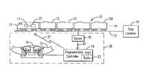
- FIG. 1there is schematically shown a train 10 including a locomotive 11 pushing a plurality of railcars 12 .
- the railcars 12include a lead railcar 12 A that is positioned at an end of the train 10 distal the locomotive 11 .
- the locomotive 11is pushing the railcars 12 (including the lead railcar 12 A) on a track 13 toward a stop location 14 where the lead railcar 12 A will be positioned for unloading or loading cargo.
- the track 13is dedicated to the stop location 14 for unloading or loading a railcar 12 , and is linked to a main track (not shown).
- the locomotive 11is remotely controlled by an operator 15 using a hand held remote control unit 16 that includes an operator interface having various input mechanisms that enable the operator to input commands relative to movement of the locomotive 11 and train 10 .
- the remote control unit 16is linked with a radio frequency module 17 (representing the onboard communication system) on the locomotive 11 that is a component of the locomotive 11 communications and power distribution system of the locomotive. For example, an operator may control the speed, stopping, and direction of the locomotive 11 by inputting commands in the remote control unit 16 .
- the operator 15via the remote control unit 16 , transmits commands to an onboard operating system 22 to control movement on the locomotive 11 and train 10 on the track 13 .
- a remote control system 30is used to restrict the speed of the locomotive 11 as the lead railcar 12 A approaches the stop location 14 , so the operator 15 can stop the train 10 so that the lead railcar 12 A is positioned at the stop location 14 .
- the remote control system 30comprises a sensor 18 positioned relative to the track 13 to detect the presence of the lead railcar 12 A on the track 13 .
- the sensor 18may be mounted on the track 13 , e.g., on a cross tie, or positioned wayside the track 13 to detect the lead railcar 12 A a predetermined distance from the stop location 14 .
- the sensor 18transmits a signal 20 to an off-board controller 19 .
- the controller 19transmits a signal 21 to the locomotive 11 .
- the signal 21is representative of a command or setting that controls movement of the train 10 on the track. Accordingly, responsive to the receipt of signal 21 , the locomotive operating system 22 sets a maximum speed setting for the locomotive 11 to travel on the track 13 toward the stop location 14 .
- the operating system 22may command the locomotive 11 to stop on the track 13 , and the operator 15 may remotely control the movement of the locomotive 11 and train 10 toward the stop location 14 ; however, the operator 15 via the remote control unit 16 can not enable the locomotive 11 to travel at a speed that exceeds the maximum speed setting.
- the remote control unit 16may be configured to require the operator 15 to enter a command before the locomotive 11 can be moved on the track 13 .
- the remote control unit 16may include an input mechanism for generating a STOP command, which when completed will enable the operator 15 to move the locomotive 11 and train 10 toward the stop location 14 .
- the senor 18is an electro-optical sensor such as a through-beam sensor or retro-reflective sensor that is hard-wired to the controller 19 , which is housed in a control box.
- the controller 19also includes a radio frequency module 23 for communicating with and transmitting signals to the communication system 17 of the locomotive 11 .
- the sensor 18may have wireless communication capabilities for transmitting signals to the controller 19 .
- the controller 19may be integrated with or be a component of the remote control unit 16 . In either case, the remote control unit 16 has an operator interface that enables the operator 15 to activate the system so that the operating system 22 on the locomotive 11 can not respond to speed setting commands that exceed the maximum speed setting for the locomotive 11 after the sensor 18 is tripped by the lead railcar 12 A.
- the speed setting selectedmay be an arbitrary setting, e.g., 1 mph (1.609 kilometers/hour) for any train 10 and locomotive 11 entering the track 13 , or the controller 19 and/or onboard operating system 22 may be programmed to determine the maximum speed setting for a given train 10 .
- the controller 19may prompt the operator 15 to enter data relative to the locomotive 11 and train 10 , such as tonnage data, to determine the maximum speed setting.
- the controller 19 or onboard operating system 22may be configured with an algorithm that also factors in the distance the lead railcar 12 A must travel to reach the stop location 14 and the grade of the track 13 to determine the speed setting.
- the controller 19when the lead railcar 12 A enters the track 13 , an operator engages the controller 19 for linking the controller 19 to the onboard communication system 17 and operating system 22 .
- Radio frequency communication systemsare commonly used at rail yards for radio communications between off-board components (such as a remote control unit) and on-board components. Accordingly, one skilled in the art would appreciate how a wayside controller can be linked to an onboard communication system, considering in part the frequency range of the communication system.
- the controller 19When the controller 19 is linked to the locomotive communication system 17 and operating system 22 , the controller may transmit data via a radio signal indicative of a track identifier.
- the operating system 22may include a database that includes data about the location or identification of the sensor 18 (or a plurality of sensors as described below) on the track 13 and data relative to one or more maximum speed settings associated with each sensor 18 location. Accordingly, when the operating system 22 receives signal 21 indicating that the lead railcar has been detected on the track 13 , the operating system 22 accesses the database to determine, select, or command a maximum speed setting associated with the sensor 18 .
- the controller 19may be programmed and/or configured so that the signal 21 includes a maximum speed setting command.
- the controller 19may access a database (not shown) that includes one or maximum speed settings associated with the sensor 18 , or one or more speed settings associated with each of a plurality of sensors (described below).
- the controllervia the module 23 , transmits a signal or command indicative of the maximum speed setting for the locomotive 11 traveling toward the stop location 14 .
- FIG. 2A second embodiment of the invention is shown in FIG. 2 and includes a plurality of sensors 24 A- 24 D positioned relative to the track 13 to detect the lead railcar 12 A on the track 13 .
- the sensors 24 A- 24 Dare spaced apart from one another and each is spaced a different predetermined distance from the stop location 14 for the lead railcar 12 A.
- Each sensor 24 A- 24 Dtransmits a signal 25 to the controller 19 when the lead railcar 12 A is detected on the track 13 .
- the controller 19may incorporate a database that includes data relative to at least one maximum speed setting, and each speed limit is associated with a respective sensor 24 A- 24 D.
- the controller 19When the controller 19 receives signal 25 from one of the sensors 24 A- 24 D, the controller 19 transmits a signal 26 to the onboard communication system represented by the module 17 and the onboard operating system 22 .
- the signal 26is indicative of a maximum speed setting for the locomotive 11 traveling on the track 13 toward the stop location 14 .
- the operating system 22then automatically sets the maximum speed setting responsive to the signal 26 .
- This maximum speed settingoverrides any speed setting that exceeds the maximum speed setting input by the operator 15 via the remote control unit 16 ; however, the operator 15 may be able to set speed settings that are less than the maximum speed setting.
- the maximum speed setting entered by the operating system 22may be associated with only the direction of movement toward the stop location 14 ; so the operator 15 may command any speed in the “pull” direction away from the stop location 14 .
- the maximum speed settingis entered for the locomotive 11 traveling in reverse; and, the operator 15 may command speeds exceeding the maximum speed setting for the locomotive 11 traveling forward.
- the maximum speed settingmay be reduced as the locomotive 11 approaches the stop location. Accordingly, when each sensor 24 A- 24 D is tripped by the lead railcar 12 A and the controller 19 transmits signal 26 to the onboard operating system 22 and communication system 17 , the maximum speed setting is entered and maintained until the controller 19 transmits a subsequent signal 26 responsive to the lead railcar 12 A being detected by the next sensor, thereby reducing the maximum speed setting. For example, when sensor 24 A is activated the signal 26 may be indicative of a 6 mph (9.656 kilometers/hour) maximum speed setting; and, when the next sensor 24 B is activated the signal 26 is indicative of a 4 mph (6.437 kilometers/hour) maximum speed setting.
- the signal 26may include a STOP command and a maximum speed setting (e.g., one mile per hour).
- the remote control unit 16may be configured such that once the train 10 and locomotive 11 have stopped; the operator 15 may input a command to move the locomotive 11 further toward the stop location 14 . In this manner, the operator may control movement of the locomotive 11 and train 10 toward the stop location 14 so the lead railcar 12 is properly positioned at the stop location 14 for loading or unloading cargo, and the lead railcar 12 A does not overrun the stop location, potentially colliding with the loading dock, building, and/or nearby equipment.
- the onboard operating system 22may be configured to identify the track 13 and the distance between each sensor 24 A- 24 D and/or the distance from each sensor 24 A- 24 D (sensor 18 in FIG. 1 ) to the stop location.
- the controller 19may transmit data relative to the track 13 identification and data relative to the distance the sensors 24 A- 24 D (sensor 18 in FIG. 1 ) are spaced relative to each other and relative to the stop location 14 .
- the onboard operating system 22may access a database that includes data relative to the distances the sensors 24 A- 24 D are spaced from each other and from the stop location, which data is associated with a track identification name or number.
- the databasemay include, or the controller 19 may transmit data relative to a maximum speed setting for each sensor 24 A- 24 D (sensor 18 in FIG. 1 ) or for one or more predetermined distances from the stop location, and a distance at which a STOP command is initiated by the operating system 22 .
- the controller 19may access sensor distance data.
- the operating system 22may initiate the speed setting commands to set a maximum speed setting at a distance a sensor 18 , 24 A- 24 D is spaced from the stop location.
- the operating system 22may initiate a STOP command so the operator 15 may disable the remote control system 30 .
- signalsmay be transmitted between communication modules to confirm that a communication link is available or whether there has been an interruption of a communication link.
- Embodiments of the inventionmay also be described as a method or computer program.
- FIG. 3there is a flow chart showing different steps of a method, which steps may also be characterized as computer modules for a computer program.
- An embodiment of the inventionmay be described as comprising the step 40 of first detecting the lead railcar 12 A on the track 13 a distance from the stop location; and then in step 44 setting a maximum speed setting for the locomotive 11 to travel toward the stop location.
- step 42the controller 19 or the onboard operating system 22 determines whether the lead railcar 12 A is a predetermined distance from the stop location 14 in order to stop the locomotive 11 .
- the operating system 22may respond to a signal received from the controller 19 by commanding the locomotive to stop a distance from the stop location 14 before operator 15 can control movement of the train 10 to the stop location 14 .
- the operating system 22may command the locomotive 11 to stop (step 48 ) when the last sensor 24 D closest to the stop location 14 is tripped.
- step 50the operating system 22 sets a maximum speed setting at which the locomotive 11 may travel toward the stop location; and, in step 52 an operator 15 remotely controls the movement of the train 10 so the lead railcar 12 A is positioned at the stop location 14 .
- step 46the locomotive 11 continues to push the railcars 12 toward the stop location 14 until a signal is received that indicates that the lead railcar 12 A is at the predetermined distance from the stop location. In this manner, the operator can control movement of the train, including the locomotive 11 and lead railcar 12 A, to the stop location 14 at a safe speed without overrunning the stop location 14 .
- Embodiments described abovemay be implemented on a suitable computer system, controller, memory, or generally a computer readable medium.
- the steps of the methods described abovemay correspond to computer instructions, logic, software code, or other computer modules disposed on the computer readable medium, e.g., floppy disc, hard drive, ASIC, remote storage, optical disc, or the like.
- the computer-implemented methods and/or computer codemay be programmed into an electronic control unit of an engine, a main control system of the locomotive, a remote control station that communicates with the locomotive unit, or the like, as described above.
Landscapes
- Engineering & Computer Science (AREA)
- Mechanical Engineering (AREA)
- Electric Propulsion And Braking For Vehicles (AREA)
- Train Traffic Observation, Control, And Security (AREA)
Abstract
Description
Claims (39)
Priority Applications (4)
| Application Number | Priority Date | Filing Date | Title |
|---|---|---|---|
| US12/139,805US8380361B2 (en) | 2008-06-16 | 2008-06-16 | System, method, and computer readable memory medium for remotely controlling the movement of a series of connected vehicles |
| PCT/US2009/044758WO2009154931A1 (en) | 2008-06-16 | 2009-05-21 | A system and method for remotely controlling the movement of a series of connected vehicles |
| EP09767243.0AEP2300300B1 (en) | 2008-06-16 | 2009-05-21 | A system and method for remotely controlling the movement of a series of connected vehicles |
| EA201001790AEA020012B1 (en) | 2008-06-16 | 2009-05-21 | A system and method for remotely controlling the movement of a series of connected vehicles |
Applications Claiming Priority (1)
| Application Number | Priority Date | Filing Date | Title |
|---|---|---|---|
| US12/139,805US8380361B2 (en) | 2008-06-16 | 2008-06-16 | System, method, and computer readable memory medium for remotely controlling the movement of a series of connected vehicles |
Publications (2)
| Publication Number | Publication Date |
|---|---|
| US20090312890A1 US20090312890A1 (en) | 2009-12-17 |
| US8380361B2true US8380361B2 (en) | 2013-02-19 |
Family
ID=40902085
Family Applications (1)
| Application Number | Title | Priority Date | Filing Date |
|---|---|---|---|
| US12/139,805Active2031-04-10US8380361B2 (en) | 2008-06-16 | 2008-06-16 | System, method, and computer readable memory medium for remotely controlling the movement of a series of connected vehicles |
Country Status (4)
| Country | Link |
|---|---|
| US (1) | US8380361B2 (en) |
| EP (1) | EP2300300B1 (en) |
| EA (1) | EA020012B1 (en) |
| WO (1) | WO2009154931A1 (en) |
Cited By (10)
| Publication number | Priority date | Publication date | Assignee | Title |
|---|---|---|---|---|
| US9061692B1 (en)* | 2011-08-09 | 2015-06-23 | Rail-Veyor Systems, Inc. | System and method for train position sensing |
| US20160068172A1 (en)* | 2014-09-04 | 2016-03-10 | Alstom Transport Technologies | Method for controlling a land transport vehicle, land transport vehicle, ground equipment and transport system |
| US9376128B2 (en) | 2013-03-14 | 2016-06-28 | General Electric Company | System and method for remotely controlling a vehicle consist |
| US9499185B2 (en) | 2013-12-20 | 2016-11-22 | Thales Canada Inc | Wayside guideway vehicle detection and switch deadlocking system with a multimodal guideway vehicle sensor |
| US9573607B2 (en) | 2013-03-15 | 2017-02-21 | Kanawha Scales & Systems, Inc. | System for accurate measurement of vehicle speeds for low speed industrial applications |
| US20180186384A1 (en)* | 2014-07-08 | 2018-07-05 | Rail-Veyor Technologies Global Inc. | Control system for an improved rail transport system for conveying bulk materials |
| US10343701B2 (en)* | 2016-02-01 | 2019-07-09 | Trinity North American Freight Car, Inc. | Railcar security system with car lighting |
| US10597055B2 (en) | 2015-11-02 | 2020-03-24 | Methode Electronics, Inc. | Locomotive control networks |
| US11851094B1 (en) | 2022-11-04 | 2023-12-26 | Bnsf Railway Company | Remote engine speed control |
| US12441378B2 (en) | 2023-11-09 | 2025-10-14 | Bnsf Railway Company | Remote engine speed control |
Families Citing this family (12)
| Publication number | Priority date | Publication date | Assignee | Title |
|---|---|---|---|---|
| DE102008050764A1 (en)* | 2008-10-09 | 2010-04-22 | Siemens Aktiengesellschaft | Method and device for increasing the stopping accuracy of a moving object |
| US8532842B2 (en)* | 2010-11-18 | 2013-09-10 | General Electric Company | System and method for remotely controlling rail vehicles |
| US8682513B2 (en)* | 2011-04-14 | 2014-03-25 | General Electric Company | Communication management system and method for a rail vehicle |
| US8805605B2 (en)* | 2011-05-09 | 2014-08-12 | General Electric Company | Scheduling system and method for a transportation network |
| KR20130001652A (en)* | 2011-06-27 | 2013-01-04 | 엘에스산전 주식회사 | The system for measuring the train location using the wireless train sensing unit |
| WO2017116466A1 (en)* | 2015-12-31 | 2017-07-06 | Patrick Tyler Joseph | Modal docking systems |
| US10279823B2 (en)* | 2016-08-08 | 2019-05-07 | General Electric Company | System for controlling or monitoring a vehicle system along a route |
| WO2018190189A1 (en)* | 2017-04-13 | 2018-10-18 | パナソニック株式会社 | Method for controlling electrically driven vehicle, and electrically driven vehicle |
| US11208127B2 (en)* | 2019-02-08 | 2021-12-28 | Cattron North America, Inc. | Systems and methods for controlling movement distances of locomotives |
| US12065179B2 (en)* | 2019-08-27 | 2024-08-20 | Cattron North America, Inc. | Systems and methods for controlling movement speed of a locomotive |
| US11318968B2 (en)* | 2019-08-27 | 2022-05-03 | Cattron North America, Inc. | Systems and methods for controlling movement speed of a locomotive |
| US20230035533A1 (en)* | 2021-07-29 | 2023-02-02 | Transportation Ip Holdings, Llc | Vehicle control system and method |
Citations (63)
| Publication number | Priority date | Publication date | Assignee | Title |
|---|---|---|---|---|
| US3519805A (en)* | 1967-11-29 | 1970-07-07 | Westinghouse Electric Corp | Vehicle stopping control apparatus |
| US3639754A (en)* | 1969-12-24 | 1972-02-01 | Gen Signal Corp | System for computing a stopping pattern signal for a vehicle |
| US3727046A (en)* | 1971-01-04 | 1973-04-10 | D Woods | Vehicle travel speed control and monitoring method and apparatus |
| US3728539A (en)* | 1971-04-08 | 1973-04-17 | Westinghouse Electric Corp | Method and apparatus for controlling a vehicle control signal |
| US3740549A (en)* | 1969-12-24 | 1973-06-19 | Westinghouse Electric Corp | Remote signaling system for train control |
| US3794977A (en)* | 1969-09-25 | 1974-02-26 | Westinghouse Electric Corp | A multiplex control system for controlling the operation of a plurality of stations |
| US3974992A (en)* | 1975-03-13 | 1976-08-17 | Westinghouse Electric Corporation | Vehicle velocity limit control method and apparatus |
| US4005838A (en)* | 1975-05-27 | 1977-02-01 | Westinghouse Air Brake Company | Station stop and speed regulation system for trains |
| US4066230A (en)* | 1975-04-02 | 1978-01-03 | Hitachi, Ltd. | Automatic braking or acceleration control system for a vehicle |
| US4066877A (en)* | 1975-04-29 | 1978-01-03 | Jeumont-Schneider | Procedure and system for driving a vehicle |
| US4093162A (en)* | 1976-02-20 | 1978-06-06 | Hitachi, Ltd. | Train operation control apparatus |
| US4095764A (en)* | 1975-11-26 | 1978-06-20 | Japanese National Railways | Spot control type automatic train stop system utilizing ground control units common to more than one block signal |
| US4208717A (en)* | 1978-06-28 | 1980-06-17 | Westinghouse Electric Corp. | Program stop control of train vehicles |
| US4327415A (en)* | 1980-01-31 | 1982-04-27 | Westinghouse Electric Corp. | Transit vehicle handback control apparatus and method |
| US4360875A (en)* | 1981-02-23 | 1982-11-23 | Behnke Robert W | Automated, door-to-door, demand-responsive public transportation system |
| US4562543A (en)* | 1983-05-04 | 1985-12-31 | Westinghouse Electric Corp. | Vehicle speed control apparatus and method |
| US4674054A (en)* | 1982-03-26 | 1987-06-16 | Sumikin Coke Company Limited | Automatic control method for coke oven working machines and fixed position control apparatus therefor |
| US4835693A (en)* | 1987-02-26 | 1989-05-30 | Utdc Inc. | Brake assurance monitor |
| US5039038A (en)* | 1983-09-14 | 1991-08-13 | Harris Corporation | Railroad communication system |
| US5437422A (en)* | 1992-02-11 | 1995-08-01 | Westinghouse Brake And Signal Holdings Limited | Railway signalling system |
| US5452870A (en)* | 1992-08-13 | 1995-09-26 | Harmon Industries, Inc. | Fixed data transmission system for controlling train movement |
| US5533695A (en)* | 1994-08-19 | 1996-07-09 | Harmon Industries, Inc. | Incremental train control system |
| US5685507A (en)* | 1994-04-01 | 1997-11-11 | Canac International Incorporated | Remote control system for a locomotive |
| US6135396A (en)* | 1997-02-07 | 2000-10-24 | Ge-Harris Railway Electronics, Llc | System and method for automatic train operation |
| US20020027495A1 (en)* | 1997-03-17 | 2002-03-07 | Ge Harris Railway Electronics, L.L.C. | Communications system and method for interconnected networks having a l linear topology, especially railways |
| US20020107616A1 (en)* | 2000-12-29 | 2002-08-08 | Dale Delaruelle | Method and system for upgrading software for controlling locomotives |
| US20020169530A1 (en)* | 1999-10-28 | 2002-11-14 | General Electric Company | Method and apparatus for vehicle data transfer optimization |
| US20020180264A1 (en)* | 2001-05-16 | 2002-12-05 | Robert Moffitt | Pneumatic brake pipe system with separate service and emergency portions |
| US20030040853A1 (en)* | 2000-07-14 | 2003-02-27 | Canac Inc. | Remote control system for locomotives |
| US6587763B2 (en)* | 2001-11-12 | 2003-07-01 | East Japan Railway Company | Train control system and method therefor |
| US20030178534A1 (en)* | 2002-03-19 | 2003-09-25 | Peltz David Michael | Remotely controlled locomotive car-kicking control |
| US20030214417A1 (en)* | 2002-05-15 | 2003-11-20 | Peltz David M. | Intelligent communications, command, and control system for a land-based vehicle |
| US6658331B2 (en)* | 2002-03-19 | 2003-12-02 | Canac, Inc. | Remote control unit for locomotive including display module for displaying command information |
| US20030236598A1 (en)* | 2002-06-24 | 2003-12-25 | Villarreal Antelo Marco Antonio | Integrated railroad system |
| US6701228B2 (en)* | 2002-05-31 | 2004-03-02 | Quantum Engineering, Inc. | Method and system for compensating for wheel wear on a train |
| US20040064223A1 (en)* | 2002-03-19 | 2004-04-01 | Canac Inc. | Remote control unit for locomotive including display module for displaying command information |
| US20040111722A1 (en)* | 2002-12-02 | 2004-06-10 | Canac Inc. | Remote control system for locomotives using a networking arrangement |
| US20050010338A1 (en)* | 2003-05-22 | 2005-01-13 | Kraeling Mark Bradshaw | Method and system for controlling locomotives |
| US6856865B2 (en)* | 2002-11-22 | 2005-02-15 | New York Air Brake Corporation | Method and apparatus of monitoring a railroad hump yard |
| US20050125113A1 (en)* | 2003-12-09 | 2005-06-09 | Wheeler Mark W. | Locomotive remote control system |
| US6970774B2 (en)* | 2002-05-31 | 2005-11-29 | Quantum Engineering, Inc. | Method and system for compensating for wheel wear on a train |
| US20060012246A1 (en)* | 2004-07-15 | 2006-01-19 | General Electric Company | Graduated train braking |
| US6996461B2 (en)* | 2002-10-10 | 2006-02-07 | Quantum Engineering, Inc. | Method and system for ensuring that a train does not pass an improperly configured device |
| US6997418B1 (en)* | 1997-11-05 | 2006-02-14 | Ge-Harris Raliway Electronics, L.L.C. | Methods and apparatus for testing a train control system |
| US20060085103A1 (en)* | 2004-04-26 | 2006-04-20 | Smith Eugene A Jr | On-board message repeater for railroad train communications system |
| US7036774B2 (en)* | 2002-10-10 | 2006-05-02 | Quantum Engineering, Inc. | Method and system for checking track integrity |
| US7069122B1 (en)* | 2002-03-08 | 2006-06-27 | Control Chief Corporation | Remote locomotive control |
| US7117137B1 (en)* | 1999-12-29 | 2006-10-03 | Ge Harris Railway Electronics, Llc | Adaptive train model |
| US7127631B2 (en)* | 2002-03-28 | 2006-10-24 | Advanced Analogic Technologies, Inc. | Single wire serial interface utilizing count of encoded clock pulses with reset |
| US7201350B2 (en)* | 2003-12-22 | 2007-04-10 | Hitachi, Ltd. | Signaling safety system |
| US7233844B2 (en)* | 2004-03-22 | 2007-06-19 | General Electric Company | Locomotive remote control system with diagnostic display |
| US20070146159A1 (en)* | 2005-12-22 | 2007-06-28 | Mamoru Kato | System for tracking railcars in a railroad environment |
| US20080068164A1 (en)* | 2006-09-12 | 2008-03-20 | International Business Machines Corporation | System and method for sensing and controlling spacing between railroad trains |
| US20080109124A1 (en)* | 2006-11-02 | 2008-05-08 | General Electric Company | Method of planning the movement of trains using pre-allocation of resources |
| US20080128562A1 (en)* | 2006-12-01 | 2008-06-05 | Ajith Kuttannair Kumar | Method and apparatus for limiting in-train forces of a railroad train |
| US20080154451A1 (en)* | 2006-12-21 | 2008-06-26 | Rail-Veyor Systems, Inc. | Method of Controlling a Rail Transport System for Conveying Bulk Materials |
| US7529201B2 (en)* | 2002-07-31 | 2009-05-05 | Cattron-Theimeg, Inc. | System and method for wireless remote control of locomotives |
| US7715956B2 (en)* | 2004-02-27 | 2010-05-11 | General Electric Company | Method and apparatus for swapping lead and remote locomotives in a distributed power railroad train |
| US20100130124A1 (en)* | 2008-11-23 | 2010-05-27 | General Electric Company | Method and apparatus for using a remote distributed power locomotive as a repeater in the communications link between a head-of-train device and an end-of-train device |
| US7756613B2 (en)* | 2005-02-25 | 2010-07-13 | Hitachi, Ltd. | Signaling system |
| US7797088B2 (en)* | 2006-05-02 | 2010-09-14 | General Electric Company | Method and apparatus for planning linked train movements |
| US20100262321A1 (en)* | 2006-03-20 | 2010-10-14 | Wolfgang Daum | System, Method and Computer Software Code for Optimizing Train Operations Considering Rail Car Parameters |
| US7937193B2 (en)* | 2003-02-27 | 2011-05-03 | General Electric Company | Method and apparatus for coordinating railway line of road and yard planners |
- 2008
- 2008-06-16USUS12/139,805patent/US8380361B2/enactiveActive
- 2009
- 2009-05-21WOPCT/US2009/044758patent/WO2009154931A1/enactiveApplication Filing
- 2009-05-21EPEP09767243.0Apatent/EP2300300B1/ennot_activeNot-in-force
- 2009-05-21EAEA201001790Apatent/EA020012B1/ennot_activeIP Right Cessation
Patent Citations (71)
| Publication number | Priority date | Publication date | Assignee | Title |
|---|---|---|---|---|
| US3519805A (en)* | 1967-11-29 | 1970-07-07 | Westinghouse Electric Corp | Vehicle stopping control apparatus |
| US3794977A (en)* | 1969-09-25 | 1974-02-26 | Westinghouse Electric Corp | A multiplex control system for controlling the operation of a plurality of stations |
| US3639754A (en)* | 1969-12-24 | 1972-02-01 | Gen Signal Corp | System for computing a stopping pattern signal for a vehicle |
| US3740549A (en)* | 1969-12-24 | 1973-06-19 | Westinghouse Electric Corp | Remote signaling system for train control |
| US3727046A (en)* | 1971-01-04 | 1973-04-10 | D Woods | Vehicle travel speed control and monitoring method and apparatus |
| US3728539A (en)* | 1971-04-08 | 1973-04-17 | Westinghouse Electric Corp | Method and apparatus for controlling a vehicle control signal |
| US3974992A (en)* | 1975-03-13 | 1976-08-17 | Westinghouse Electric Corporation | Vehicle velocity limit control method and apparatus |
| US4066230A (en)* | 1975-04-02 | 1978-01-03 | Hitachi, Ltd. | Automatic braking or acceleration control system for a vehicle |
| US4066877A (en)* | 1975-04-29 | 1978-01-03 | Jeumont-Schneider | Procedure and system for driving a vehicle |
| US4005838A (en)* | 1975-05-27 | 1977-02-01 | Westinghouse Air Brake Company | Station stop and speed regulation system for trains |
| US4095764A (en)* | 1975-11-26 | 1978-06-20 | Japanese National Railways | Spot control type automatic train stop system utilizing ground control units common to more than one block signal |
| US4093162A (en)* | 1976-02-20 | 1978-06-06 | Hitachi, Ltd. | Train operation control apparatus |
| US4208717A (en)* | 1978-06-28 | 1980-06-17 | Westinghouse Electric Corp. | Program stop control of train vehicles |
| US4327415A (en)* | 1980-01-31 | 1982-04-27 | Westinghouse Electric Corp. | Transit vehicle handback control apparatus and method |
| US4360875A (en)* | 1981-02-23 | 1982-11-23 | Behnke Robert W | Automated, door-to-door, demand-responsive public transportation system |
| US4674054A (en)* | 1982-03-26 | 1987-06-16 | Sumikin Coke Company Limited | Automatic control method for coke oven working machines and fixed position control apparatus therefor |
| US4562543A (en)* | 1983-05-04 | 1985-12-31 | Westinghouse Electric Corp. | Vehicle speed control apparatus and method |
| US5039038A (en)* | 1983-09-14 | 1991-08-13 | Harris Corporation | Railroad communication system |
| US4835693A (en)* | 1987-02-26 | 1989-05-30 | Utdc Inc. | Brake assurance monitor |
| US5437422A (en)* | 1992-02-11 | 1995-08-01 | Westinghouse Brake And Signal Holdings Limited | Railway signalling system |
| US5452870A (en)* | 1992-08-13 | 1995-09-26 | Harmon Industries, Inc. | Fixed data transmission system for controlling train movement |
| US5685507A (en)* | 1994-04-01 | 1997-11-11 | Canac International Incorporated | Remote control system for a locomotive |
| US5533695A (en)* | 1994-08-19 | 1996-07-09 | Harmon Industries, Inc. | Incremental train control system |
| US6135396A (en)* | 1997-02-07 | 2000-10-24 | Ge-Harris Railway Electronics, Llc | System and method for automatic train operation |
| US20020027495A1 (en)* | 1997-03-17 | 2002-03-07 | Ge Harris Railway Electronics, L.L.C. | Communications system and method for interconnected networks having a l linear topology, especially railways |
| US6400281B1 (en)* | 1997-03-17 | 2002-06-04 | Albert Donald Darby, Jr. | Communications system and method for interconnected networks having a linear topology, especially railways |
| US6997418B1 (en)* | 1997-11-05 | 2006-02-14 | Ge-Harris Raliway Electronics, L.L.C. | Methods and apparatus for testing a train control system |
| US20020169530A1 (en)* | 1999-10-28 | 2002-11-14 | General Electric Company | Method and apparatus for vehicle data transfer optimization |
| US7117137B1 (en)* | 1999-12-29 | 2006-10-03 | Ge Harris Railway Electronics, Llc | Adaptive train model |
| US20030040853A1 (en)* | 2000-07-14 | 2003-02-27 | Canac Inc. | Remote control system for locomotives |
| US20020107616A1 (en)* | 2000-12-29 | 2002-08-08 | Dale Delaruelle | Method and system for upgrading software for controlling locomotives |
| US20020180264A1 (en)* | 2001-05-16 | 2002-12-05 | Robert Moffitt | Pneumatic brake pipe system with separate service and emergency portions |
| US6587763B2 (en)* | 2001-11-12 | 2003-07-01 | East Japan Railway Company | Train control system and method therefor |
| US7069122B1 (en)* | 2002-03-08 | 2006-06-27 | Control Chief Corporation | Remote locomotive control |
| US7520472B2 (en)* | 2002-03-19 | 2009-04-21 | General Electric Company | Remotely controlled locomotive car-kicking control |
| US6658331B2 (en)* | 2002-03-19 | 2003-12-02 | Canac, Inc. | Remote control unit for locomotive including display module for displaying command information |
| US20030178534A1 (en)* | 2002-03-19 | 2003-09-25 | Peltz David Michael | Remotely controlled locomotive car-kicking control |
| US20040064223A1 (en)* | 2002-03-19 | 2004-04-01 | Canac Inc. | Remote control unit for locomotive including display module for displaying command information |
| US20050253022A1 (en)* | 2002-03-19 | 2005-11-17 | Peltz David M | Remotely controlled locomotive car-kicking control |
| US7127631B2 (en)* | 2002-03-28 | 2006-10-24 | Advanced Analogic Technologies, Inc. | Single wire serial interface utilizing count of encoded clock pulses with reset |
| US20030214417A1 (en)* | 2002-05-15 | 2003-11-20 | Peltz David M. | Intelligent communications, command, and control system for a land-based vehicle |
| US6970774B2 (en)* | 2002-05-31 | 2005-11-29 | Quantum Engineering, Inc. | Method and system for compensating for wheel wear on a train |
| US6701228B2 (en)* | 2002-05-31 | 2004-03-02 | Quantum Engineering, Inc. | Method and system for compensating for wheel wear on a train |
| US20030236598A1 (en)* | 2002-06-24 | 2003-12-25 | Villarreal Antelo Marco Antonio | Integrated railroad system |
| US6799097B2 (en)* | 2002-06-24 | 2004-09-28 | Modular Mining Systems, Inc. | Integrated railroad system |
| US7792089B2 (en)* | 2002-07-31 | 2010-09-07 | Cattron-Theimeg, Inc. | System and method for wireless remote control of locomotives |
| US7529201B2 (en)* | 2002-07-31 | 2009-05-05 | Cattron-Theimeg, Inc. | System and method for wireless remote control of locomotives |
| US7036774B2 (en)* | 2002-10-10 | 2006-05-02 | Quantum Engineering, Inc. | Method and system for checking track integrity |
| US6996461B2 (en)* | 2002-10-10 | 2006-02-07 | Quantum Engineering, Inc. | Method and system for ensuring that a train does not pass an improperly configured device |
| US7236860B2 (en)* | 2002-10-10 | 2007-06-26 | Quantum Engineering, Inc. | Method and system for ensuring that a train does not pass an improperly configured device |
| US6856865B2 (en)* | 2002-11-22 | 2005-02-15 | New York Air Brake Corporation | Method and apparatus of monitoring a railroad hump yard |
| US20040111722A1 (en)* | 2002-12-02 | 2004-06-10 | Canac Inc. | Remote control system for locomotives using a networking arrangement |
| US7937193B2 (en)* | 2003-02-27 | 2011-05-03 | General Electric Company | Method and apparatus for coordinating railway line of road and yard planners |
| US20050010338A1 (en)* | 2003-05-22 | 2005-01-13 | Kraeling Mark Bradshaw | Method and system for controlling locomotives |
| US20050125113A1 (en)* | 2003-12-09 | 2005-06-09 | Wheeler Mark W. | Locomotive remote control system |
| US7201350B2 (en)* | 2003-12-22 | 2007-04-10 | Hitachi, Ltd. | Signaling safety system |
| US20100204858A1 (en)* | 2004-02-27 | 2010-08-12 | General Electric Company | Method and Apparatus for Swapping Lead and Remote Locomotives in a Distributed Power Railroad Train |
| US7715956B2 (en)* | 2004-02-27 | 2010-05-11 | General Electric Company | Method and apparatus for swapping lead and remote locomotives in a distributed power railroad train |
| US7233844B2 (en)* | 2004-03-22 | 2007-06-19 | General Electric Company | Locomotive remote control system with diagnostic display |
| US20060085103A1 (en)* | 2004-04-26 | 2006-04-20 | Smith Eugene A Jr | On-board message repeater for railroad train communications system |
| US20060012246A1 (en)* | 2004-07-15 | 2006-01-19 | General Electric Company | Graduated train braking |
| US7756613B2 (en)* | 2005-02-25 | 2010-07-13 | Hitachi, Ltd. | Signaling system |
| WO2006093536A1 (en) | 2005-02-25 | 2006-09-08 | General Electric Company | Graduated train braking |
| US20070146159A1 (en)* | 2005-12-22 | 2007-06-28 | Mamoru Kato | System for tracking railcars in a railroad environment |
| US20100262321A1 (en)* | 2006-03-20 | 2010-10-14 | Wolfgang Daum | System, Method and Computer Software Code for Optimizing Train Operations Considering Rail Car Parameters |
| US7797088B2 (en)* | 2006-05-02 | 2010-09-14 | General Electric Company | Method and apparatus for planning linked train movements |
| US20080068164A1 (en)* | 2006-09-12 | 2008-03-20 | International Business Machines Corporation | System and method for sensing and controlling spacing between railroad trains |
| US20080109124A1 (en)* | 2006-11-02 | 2008-05-08 | General Electric Company | Method of planning the movement of trains using pre-allocation of resources |
| US20080128562A1 (en)* | 2006-12-01 | 2008-06-05 | Ajith Kuttannair Kumar | Method and apparatus for limiting in-train forces of a railroad train |
| US20080154451A1 (en)* | 2006-12-21 | 2008-06-26 | Rail-Veyor Systems, Inc. | Method of Controlling a Rail Transport System for Conveying Bulk Materials |
| US20100130124A1 (en)* | 2008-11-23 | 2010-05-27 | General Electric Company | Method and apparatus for using a remote distributed power locomotive as a repeater in the communications link between a head-of-train device and an end-of-train device |
Non-Patent Citations (1)
| Title |
|---|
| Boutonnet et al., "Les Locotracteurs Telecommandables Sont En Service," Revue Generale des Chemins de Fer, Centrale des Revues, Oct. 1, 1990, pp. 23-28, No. 10, Paris, France. |
Cited By (14)
| Publication number | Priority date | Publication date | Assignee | Title |
|---|---|---|---|---|
| US9714042B1 (en) | 2011-08-09 | 2017-07-25 | Rail-Veyor Systems, Inc. | System and method for train position sensing |
| US9061692B1 (en)* | 2011-08-09 | 2015-06-23 | Rail-Veyor Systems, Inc. | System and method for train position sensing |
| US9376128B2 (en) | 2013-03-14 | 2016-06-28 | General Electric Company | System and method for remotely controlling a vehicle consist |
| US9573607B2 (en) | 2013-03-15 | 2017-02-21 | Kanawha Scales & Systems, Inc. | System for accurate measurement of vehicle speeds for low speed industrial applications |
| US9499185B2 (en) | 2013-12-20 | 2016-11-22 | Thales Canada Inc | Wayside guideway vehicle detection and switch deadlocking system with a multimodal guideway vehicle sensor |
| US20180186384A1 (en)* | 2014-07-08 | 2018-07-05 | Rail-Veyor Technologies Global Inc. | Control system for an improved rail transport system for conveying bulk materials |
| US9796399B2 (en)* | 2014-09-04 | 2017-10-24 | Alstom Transport Technologies | Method for controlling a land transport vehicle, land transport vehicle, ground equipment and transport system |
| US9809234B2 (en)* | 2014-09-04 | 2017-11-07 | Alstom Transport Technologies | Method for controlling a land transport vehicle, land transport vehicle, ground equipment and transport system |
| US9811137B2 (en)* | 2014-09-04 | 2017-11-07 | Alstom Transport Technologies | Method for controlling a land transport vehicle, land transport vehicle, ground equipment and transport system |
| US20160068172A1 (en)* | 2014-09-04 | 2016-03-10 | Alstom Transport Technologies | Method for controlling a land transport vehicle, land transport vehicle, ground equipment and transport system |
| US10597055B2 (en) | 2015-11-02 | 2020-03-24 | Methode Electronics, Inc. | Locomotive control networks |
| US10343701B2 (en)* | 2016-02-01 | 2019-07-09 | Trinity North American Freight Car, Inc. | Railcar security system with car lighting |
| US11851094B1 (en) | 2022-11-04 | 2023-12-26 | Bnsf Railway Company | Remote engine speed control |
| US12441378B2 (en) | 2023-11-09 | 2025-10-14 | Bnsf Railway Company | Remote engine speed control |
Also Published As
| Publication number | Publication date |
|---|---|
| EA201001790A1 (en) | 2011-08-30 |
| US20090312890A1 (en) | 2009-12-17 |
| EP2300300A1 (en) | 2011-03-30 |
| EA020012B1 (en) | 2014-08-29 |
| EP2300300B1 (en) | 2014-03-19 |
| WO2009154931A1 (en) | 2009-12-23 |
Similar Documents
| Publication | Publication Date | Title |
|---|---|---|
| US8380361B2 (en) | System, method, and computer readable memory medium for remotely controlling the movement of a series of connected vehicles | |
| CN107709136B (en) | Method and device for determining driving authorization for a rail vehicle | |
| TWI539254B (en) | Vehicle system and vehicle control method | |
| AU2004243288B2 (en) | Method and system for controlling locomotives | |
| US11479282B2 (en) | Method, vehicle device and controller for operating a track-bound traffic system | |
| US9327740B2 (en) | Method and system for communicating data with vehicles | |
| CN112810629A (en) | System and method for monitoring a moving vehicle | |
| US8400270B2 (en) | Systems and methods for determining an operating state using RFID | |
| US11385066B2 (en) | Vehicle navigation and control system and method | |
| WO2019024517A1 (en) | Automatic driving method, apparatus and system of train | |
| RU2705035C1 (en) | Method and system for controlling rolling stock during thrusting and breaking from railroads hump yard | |
| US20230211817A1 (en) | Vehicle system and method | |
| CN112550343A (en) | Automatic trailer method and device suitable for freight train | |
| US20210139053A1 (en) | On-board control apparatus and platform-door control system | |
| CN111762233A (en) | Safety protection system and method for molten iron combined transport vehicle handover | |
| JP2007161253A (en) | Train operation management method and train operation management system | |
| CN113247052B (en) | Train positioning method and system | |
| KR101989797B1 (en) | System for controlling drives of automatic guided vehicle in the intersection and method thereof | |
| JP3607966B2 (en) | Driving support system | |
| KR101484974B1 (en) | Train Operating Control System using RFID | |
| CN114444944A (en) | Integrated information platform for molten iron combined transportation | |
| CN111762232A (en) | Safety protection system and method for molten iron combined transport vehicle handover | |
| CN115771545B (en) | Railway shunting anti-collision warning method and system | |
| EP4428516A1 (en) | Vehicle system and method | |
| Lee et al. | Study on train collision avoidance system for securing safe distance between trains |
Legal Events
| Date | Code | Title | Description |
|---|---|---|---|
| AS | Assignment | Owner name:GENERAL ELECTRIC COMPANY, FLORIDA Free format text:ASSIGNMENT OF ASSIGNORS INTEREST;ASSIGNOR:EVANS, JAY;REEL/FRAME:021101/0188 Effective date:20080616 | |
| AS | Assignment | Owner name:GENERAL ELECTRIC COMPANY, FLORIDA Free format text:ASSIGNMENT OF ASSIGNORS INTEREST;ASSIGNOR:EVANS, JAY;REEL/FRAME:021182/0576 Effective date:20080616 | |
| AS | Assignment | Owner name:GENERAL ELECTRIC COMPANY, NEW YORK Free format text:CORRECTIVE ASSIGNMENT TO CORRECT THE ASSIGNEE ADDRESS FROM "FLORIDA" TO "NEW YORK" PREVIOUSLY RECORDED ON REEL 021101 FRAME 0188. ASSIGNOR(S) HEREBY CONFIRMS THE CORRECT STATE OF ASSIGNEE;ASSIGNOR:EVANS, JAY;REEL/FRAME:023202/0176 Effective date:20080616 | |
| STCF | Information on status: patent grant | Free format text:PATENTED CASE | |
| FPAY | Fee payment | Year of fee payment:4 | |
| AS | Assignment | Owner name:GE GLOBAL SOURCING LLC, CONNECTICUT Free format text:ASSIGNMENT OF ASSIGNORS INTEREST;ASSIGNOR:GENERAL ELECTRIC COMPANY;REEL/FRAME:047736/0140 Effective date:20181101 | |
| MAFP | Maintenance fee payment | Free format text:PAYMENT OF MAINTENANCE FEE, 8TH YEAR, LARGE ENTITY (ORIGINAL EVENT CODE: M1552); ENTITY STATUS OF PATENT OWNER: LARGE ENTITY Year of fee payment:8 | |
| MAFP | Maintenance fee payment | Free format text:PAYMENT OF MAINTENANCE FEE, 12TH YEAR, LARGE ENTITY (ORIGINAL EVENT CODE: M1553); ENTITY STATUS OF PATENT OWNER: LARGE ENTITY Year of fee payment:12 |