US8380126B1 - Reliable communications for wireless devices - Google Patents
Reliable communications for wireless devicesDownload PDFInfo
- Publication number
- US8380126B1 US8380126B1US11/250,982US25098205AUS8380126B1US 8380126 B1US8380126 B1US 8380126B1US 25098205 AUS25098205 AUS 25098205AUS 8380126 B1US8380126 B1US 8380126B1
- Authority
- US
- United States
- Prior art keywords
- channel
- wireless
- primary
- communications
- communication
- Prior art date
- Legal status (The legal status is an assumption and is not a legal conclusion. Google has not performed a legal analysis and makes no representation as to the accuracy of the status listed.)
- Active, expires
Links
- FRBZLYTWXMMDLE-UHFFFAOYSA-NC(C1CC1)C1=CC=CC1Chemical compoundC(C1CC1)C1=CC=CC1FRBZLYTWXMMDLE-UHFFFAOYSA-N0.000description1
- PGQCMNXDZOLRQA-UHFFFAOYSA-NIC1=CCC=C1Chemical compoundIC1=CCC=C1PGQCMNXDZOLRQA-UHFFFAOYSA-N0.000description1
Images


Classifications
- A—HUMAN NECESSITIES
- A61—MEDICAL OR VETERINARY SCIENCE; HYGIENE
- A61B—DIAGNOSIS; SURGERY; IDENTIFICATION
- A61B5/00—Measuring for diagnostic purposes; Identification of persons
- A61B5/74—Details of notification to user or communication with user or patient; User input means
- A61B5/7475—User input or interface means, e.g. keyboard, pointing device, joystick
- H—ELECTRICITY
- H04—ELECTRIC COMMUNICATION TECHNIQUE
- H04B—TRANSMISSION
- H04B1/00—Details of transmission systems, not covered by a single one of groups H04B3/00 - H04B13/00; Details of transmission systems not characterised by the medium used for transmission
- H04B1/74—Details of transmission systems, not covered by a single one of groups H04B3/00 - H04B13/00; Details of transmission systems not characterised by the medium used for transmission for increasing reliability, e.g. using redundant or spare channels or apparatus
- H—ELECTRICITY
- H04—ELECTRIC COMMUNICATION TECHNIQUE
- H04L—TRANSMISSION OF DIGITAL INFORMATION, e.g. TELEGRAPHIC COMMUNICATION
- H04L1/00—Arrangements for detecting or preventing errors in the information received
- H04L1/22—Arrangements for detecting or preventing errors in the information received using redundant apparatus to increase reliability
- A—HUMAN NECESSITIES
- A61—MEDICAL OR VETERINARY SCIENCE; HYGIENE
- A61B—DIAGNOSIS; SURGERY; IDENTIFICATION
- A61B17/00—Surgical instruments, devices or methods
- A61B2017/00973—Surgical instruments, devices or methods pedal-operated
- A—HUMAN NECESSITIES
- A61—MEDICAL OR VETERINARY SCIENCE; HYGIENE
- A61B—DIAGNOSIS; SURGERY; IDENTIFICATION
- A61B5/00—Measuring for diagnostic purposes; Identification of persons
- A61B5/0002—Remote monitoring of patients using telemetry, e.g. transmission of vital signals via a communication network
Definitions
- the present inventionrelates generally to the field of medical systems, and more specifically to managing reliable, high availability communications for wireless medical devices.
- non-fixed devicesmeeting or complying with the Institute of Electrical and Electronics Engineers (IEEE) 802.11g and Ericsson BluetoothTM specifications provide short-range radio technology to enable for wireless communications. These technologies allow for wireless transmission of signals over short distances between computers and other electronic devices.
- BluetoothTM enabled devicesare capable of an approximate 10-meter transmission range at data rates up to 720 kilobits/sec, and can provide better security features than devices implementing IEEE 802.11g communications.
- line-of-sight wireless light wave technologyincluding Infrared Data Association (IrDA) techniques, may also be employed by product designers to realize wireless connections.
- IrDAInfrared Data Association
- BluetoothTM or IEEE 802.11g specificationswill yield a communications path between wireless non-fixed devices and subsystems.
- Each specificationalso addresses providing an interference resistant communications path with automatic error detection and correction capabilities for transmitting and receiving of control signals, data, and information.
- Non-fixed wireless medical subsystems and devicesrequire a continuous, reliable, and high availability communications network to ensure uninterrupted operation of an instrument host system.
- the above-cited specificationsdo not provide for a continuous, reliable, and highly available communication experience under all operating theater conditions. Due to the critical health support requirements for medical equipment and the potential catastrophic consequences of a communications connection failure in such equipment, effective deployment of medical systems incorporating wireless devices require a highly reliable communications management scheme to ensure a reliable connection from the instrument host system is constantly available to fielded non-fixed wireless subsystems and devices. Neither of the foregoing specifications guarantees this high a level of reliable communications management.
- Active wireless medical deviceswhen used under normal operation, are exposed to numerous sources of electrical and magnetic interference, environmental conditions, and reliability issues. Electrical and magnetic interference may cause a loss of signal strength or degrade the signal quality sufficient to cause a wireless communications path to disconnect. For example, a single wireless BluetoothTM connection requires a few seconds to re-establish a failed connection. During this reconnect time period, the surgeon can lose remote control of the surgical system and be unable to control the medical equipment. This reconnection time delay is not desirable or suitable for safety critical devices or equipment.
- footpedalincorporates the ability to detect the footpedal returning to a non-active state independent of the linear position detection, thus serving as a fail-safe trigger. If this independent fail-safe trigger is directed through a single wireless channel, communication of this trigger is subject to a single-point-of-failure arrangement that loses any redundancy benefit.
- Reliable wireless device communication management schemes in this environmentmust therefore not only provide a reliable continuous communications path but also a mechanism for monitoring and reporting the signal strength and signal quality condition for wireless subsystems and devices when subjected to external interference and environmental conditions found in the operating theater.
- a method for managing communications between a plurality of medical devicescomprises providing a wireless connection between at least two medical devices, the at least two medical devices comprising a primary medical device and a secondary medical device, causing the primary medical device to transmit and the secondary medical device to receive state signals wirelessly across a plurality of communication data channels, and reporting a non-active state for one of the plurality of data channels from the primary medical device to the secondary medical device using the plurality of communication data channels.
- a connectivity management systemcomprising a wireless controller configured to communicate over a plurality of communications data channels.
- the connectivity management systemfurther comprises a wireless medical device configured to communicate over the plurality of communications data channels, wherein the wireless controller and wireless medical device are connected and exchange state information across the plurality of communications data channels and alternate communication between at least two of the communications data channels based on observed channel quality.
- FIG. 1is a block diagram illustrating the present design components and interfaces of a wireless medical system with a communications management subsystem
- FIG. 2illustrates components of the present design and interfaces of a primary and backup wireless communications network
- FIG. 3Ashows components of the present design and interfaces of a communications management subsystem establishing a primary and a backup communication path;
- FIG. 3Billustrates components and interfaces of a communications management subsystem switching from a failed primary data channel to a backup data channel
- FIG. 4shows a footpedal that may be employed in accordance with the current design
- FIG. 5shows the conceptual connections between the footpedal, base unit, and power source of the present design.
- a communications management arrangement or subsystemmay provide a mechanism for monitoring and reporting the health and status of a plurality of data channels used to connect wireless devices, particularly in instances where the wireless device or devices operate in a medical theater, including but not limited to an operating room.
- the communications management subsystemmay include a novel redundant wireless data channel arrangement to eliminate any potential single-points-of-failure within the communications network.
- the present design methodis directed to managing a reliable redundant wireless communications network to support a wireless device, typically employed in a medical scenario but applicable in other scenarios, where communications management includes the monitoring health and status of one or more data channels, reporting health and status of the data channels, indicating current communications path connection quality condition to a user, and automatically switching to a backup communication path when necessary to ensure continuous reliable high availability communications.
- one embodiment of the present designis a phacoemulsification system or method using a surgical system that incorporates a wireless medical device, such as a wireless footswitch, to control the surgical system.
- a wireless medical devicesuch as a wireless footswitch
- wireless deviceor “wireless medical device” or “non-fixed wireless device” or the like as used herein means a device capable of receiving and/or transmitting information wirelessly, i.e. over the air, using either a radio, light wave (e.g. infrared) or other communication technique that does not require a physical connection, such as a wire.
- Wireless devicesthat may realize the reception and transmission of data include, but are not limited to, those devices meeting or complying with the Institute of Electrical and Electronics Engineers (IEEE) 802.11 and Ericson BluetoothTM specifications for short range radio technology, or an Infrared Data Association (IrDA) light wave technique.
- IEEEInstitute of Electrical and Electronics Engineers
- IrDAInfrared Data Association
- the present designprovides an arrangement that enables users of wireless medical devices to continue uninterrupted work independent of individual wireless data channel health.
- This arrangementprovides monitoring and reporting information services in regard to the wireless medical device communications network condition, including providing automatic switching to a backup communications channel when necessary to continue transmitting and receiving data to ensure continuous, reliable, and safe use.
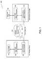
- FIG. 1illustrates the present design components and interfaces of a wireless medical system 100 , where the particular embodiment illustrated in FIG. 1 contemplates that the wireless or remote device is a footpedal.
- the medical system 100 in this embodimentincludes a wireless device 101 , a wireless controller 102 , an instrument host system 120 , and a wireless communications network 130 .
- a footpedal 103may transmit control signals relating internal physical switch position information (not shown in this view; see FIG. 4 ) as input to a footpedal slave subsystem 105 .
- the footpedal slave subsystem 105may provide data indicating physical and virtual switch position information to a communications slave subsystem 107 .
- the communication slave subsystem 107typically comprising a transmitter and receiver operating, for example, using the wireless 802.11g or BluetoothTM protocols, may transmit this data using a wireless communication network 130 via antenna 131 , or alternatively a fixed cable 140 wired mode.
- the wireless communications network 130may employ any network communications protocol sufficient for serving the purposes of communications network 130 .
- the term “communications network” or “communications system” as used hereinis used in its most expansive sense and applies to any communications system through which any information may be transferred to and from a wireless device, and includes, without limitation, transmission by static, active, dynamic communications protocols or otherwise. While the present design may use various communication protocols, it will be discussed herein implementing and complying with Ericsson's BluetoothTM protocol specification. Slight changes may be made to the enclosed to enable operation using other or complementary communications protocols, and the use and implementation of the present design using these other protocols is intended to be within the scope of the current design.
- a first channelmay run according to a BluetoothTM protocol while a second channel may run according to an 802.11g protocol.
- Different parameterssuch as different transmission frequencies or data rates may also be employed over the plurality of channels offered in the current design.
- Other protocolsmay be employed, including but not limited to IrDA (infrared data).
- the systemmay provide at least one active channel together with cross checking capability provided by another channel, typically utilizing a cross checking mechanism such as checksums to evaluate signal quality and/or correctness.
- the active channelconstantly transmits data while the secondary channel transmits cross checking information, and upon failure of the cross check, transmission switches to the secondary channel.
- the wireless controller 102receives wireless device 101 transmissions via a communication master subsystem 106 , typically comprising a transmitter and receiver.
- the communications master subsystem 106receives and forwards data, including but not limited to information such as footpedal position and state parameters, to the footpedal master subsystem 104 .
- Position and state informationmay include but is not limited to representing relative pitch and yaw travel of the footpedal 103 , as well as buttons, switches, or other input devices on footpedal 103 .
- the communication slave subsystem 107may provide redundant wireless connections supporting a primary communication path, and one or more backup communication paths to ensure reliable exchange of data.
- the footpedal master subsystemmay transfer this data to an instrument host 120 .
- the instrument host 120may use the received data to control and operate the behavior of various embedded features and functions including irrigation, aspiration, electrical cauterization, and various cutting actions, such as phacoemulsification and vitrectomy procedures, and providing pressure for posterior ocular segment surgery, such as viscous fluid injection.
- the instrument host 120may use the data to effectuate a switch between handpieces, modes, or modules, such as switching between a phacoemulsification procedure and a vitreous cutting procedure.
- a switchmay be effectuated by the operator providing an indication on a switch or button on footpedal 103 that indicates a desired switch between procedures or modules.
- the instrument host 120may provide information to the footpedal master subsystem 104 , including but not limited to information such as control signals indicating the amplitude and duration to command the footpedal 103 vibration device, such as a vibration motor or solenoid actuator (not shown), sufficient to provide tactile feedback to the surgeon.
- the instrument host 120may provide information to the footpedal master subsystem 104 for the purposes of providing cues, such as activating status lights and emitting sounds, on the footpedal to alert the operator.
- the footpedal master subsystem 104may forward information received from the instrumentation host 120 to the communications master subsystem 106 .
- the communication master subsystem 106may transmit this information across the wireless communications network 130 to the wireless device 101 communication slave subsystem 107 .
- the communications slave subsystem 107may deliver the control signal information to the footpedal slave subsystem 105 , which in turn may deliver these signals to the footpedal 103 ; thus resulting in the operation of the vibration motor or other feedback mechanisms within the footpedal 103 in accordance with the supplied control signal amplitude and duration.
- the communications master subsystem 106 and the communications slave subsystem 107may monitor the health and status of the primary and backup Bluetooth data channels, including but not limited to data channel signal quality and strength. Details describing this aspect of the communications master subsystem 106 and the communications slave subsystem 107 are provided below.
- footpedal master subsystem 104 and communications master subsystem 106may alternatively be comprised of a single firmware device or a set of distributed firmware devices that fulfill the functionality of pedal master subsystem 104 and communications master subsystem 106 . Additionally, while depicted as multiple elements, footpedal slave subsystem 105 and communications slave subsystem 107 may also be comprised of a single firmware device or a set of distributed firmware devices that fulfill the functionality of pedal master subsystem 104 and communications master subsystem 106 .
- FIG. 2illustrates components of the present design and interfaces of the wireless communications network 130 to the wireless device 101 and wireless controller 102 , where the embodiment illustrated in FIG. 2 contemplates that the wireless transmission and reception of data and information is realized using a primary communication path and one or more secondary backup communication paths.
- Datais typically transferred in many protocols in the form of packets of data, but other data transfer formats may be employed. Packets typically contain fields such as headers and lower level protocol information embedded in the packet. Data is transferred via packets using certain common protocols. In an alternate embodiment of the present design, communications and packets could be divided between channels, such as pitch packets for a footpedal movement on one channel and yaw packets for footpedal movement on the other. Such a design would enable faster data transfer, may save power, and may enable cross checking as discussed below, but failure of one channel would require relatively immediate transfer to the other channel and carrying both pitch and yaw packets in this example over the remaining channel.
- the userpowers on the instrument host 120 .
- the communications master subsystem 106 within the wireless controller 102determines if a physical connection supporting a fixed cable 140 wired mode is available (not shown in this view; see FIG. 1 ). If a physical cable is present, the communications master subsystem 106 may activate and establish communications with the wireless device 101 communications slave subsystem 107 across this fixed cable 140 as in typical conventional systems.
- the wireless controller 102may invoke a wireless mode by activating and establishing communications with the wireless device 101 communications slave subsystem 107 .
- a wireless communications network 130replaces the fixed cable 140 found in the wired mode to enable exchange of control signals, data, and information between the wireless controller 102 and the wireless device 101 .
- the wireless controller 102 communications master subsystem 106initiates a wireless device-searching mode to locate and pair with an available wireless device 101 communications slave subsystem 107 to establish a primary wireless communications path across the wireless communications network 130 .
- the wireless controller 102searches for a unique wireless device 101 using, for example, BluetoothTM short-range radio techniques. Searching is complete when the correct wireless device 101 is located. At this point, the wireless controller 102 ‘pairs-up’ or ‘matches’ with the unique wireless device 101 to enable communication of control signal and other device information, such as battery condition.
- the specific techniques and details associated with Bluetooth searching and “pairing” mechanismare generally known to those skilled in the art. Alternate searching and locating techniques may be employed depending on the transmission protocol employed. For example, 802.11g may employ link control procedures known to those skilled in the art and specified by the standard, while a protocol such as IrDa may employ optical locating and searching techniques again known to those skilled in the art.
- the communications master subsystem 106establishes one or more backup wireless communication paths in a similar manner over the wireless communications network 130 .
- the master controller 208 imbedded within the communications master subsystem 106establishes a primary connection through Bluetooth primary 210 transceiver subsystem and establishes a backup connection through Bluetooth backup 212 transceiver subsystem. If more than one backup communication path is present and available, the master controller also establishes these communication paths as additional backup connections between 214 and 215 and so forth.
- the footpedal master and footpedal slave subsystems, 104 and 105 respectivelymay operate in this embodiment using one or more BluetoothTM data channels.
- a successful start-up sequenceprovides a reliable and high availability redundant communications network between the instrument host 120 and footpedal 103 .
- the instrument host 120When the instrument host is powered on and operational, the instrument host 120 generates information for conveyance to the footpedal 103 .
- the instrument host 120may request the footpedal subsystem 105 to “set” or program a specific inactive range for both left and right yaw, provide a programmable threshold to the footpedal subsystem 105 for both left and right virtual switches and buttons (not shown in this view), or request the footpedal subsystem to report an installed firmware version number, serial number, or other identifying information.
- the master controller 208provides the same information, in the form of a data stream, for transmission to both the primary communications path at 210 and the backup communications path at 212 .
- the master controller 208manages the transmission of the same data stream across both the primary and backup communications paths by first transmitting the data stream across the primary communications path, and then switching to the backup communications path and transmitting the same data stream as originally provided to the primary communication path, or vice versa. This method provides redundant communications between the wireless controller 102 and the wireless device 101 .
- the master controller 208manages the alternating or ‘flip-flopping’ between the primary and backup communications path in a manner wherein both paths are never transmitting at the same time.
- Alternating between channelsensures that two copies of the same data stream are transmitted to the communications slave subsystem 107 within the wireless device 101 .
- the master controller 208may continuously monitor the health and status of all active paths. Monitoring the health and status may include measuring signal strength, signal quality, or checking data integrity and observing other relevant parameters to determine current path connection condition and reporting the measured result to the communications master subsystem 106 .
- the wireless device 101may report additional observed non-fixed device management information, including but not limited to current battery charge condition, not pertaining to communications path integrity through the communications network 130 to the wireless controller 102 .
- the communications path health and status observed by the communications slave subsystem 107may be delivered to the footpedal slave subsystem 105 for presentation to the user.
- the footpedal slave subsystem 105may provide a visual alert, an audible alert, and any combination thereof to the user.
- the visual alertmay be realized by blinking an LED when either path becomes disconnected, wherein a constantly lit LED may indicate both communications paths are connected and available for use.
- a periodic audible alertmay be sounded when either communications path becomes disconnected.
- One alternate embodiment of the present designmay include a transmission arrangement wherein data is transmitted on one channel until a failure is sensed and then switching to the second channel upon sensing the failure.
- the advantage to such a designis the ability to save power, but the down side can be encountered when channel failure is not sensed quickly enough or channels cannot be switched quickly enough to preserve data.
- power savingsis a consideration and constant uninterrupted performance is less critical, such a design may be employed.
- a shutoff safety mechanism or a notificationmay be employed when signal strength or quality on both channels drops below a certain threshold.
- a “fail safe” mode or statemay be employed when both channels encounter transmission problems, and the system may in one embodiment switch from wireless transmission of signals to transmission across fixed cable 140 .
- the systemmay shut down or notify operators, such as by audio and/or visual cue.
- the audio and/or visual cueindicates that a dual channel or multiple channel signal transmission problem exists.
- Such an implementationcan be useful in crowded, tight, or noisy environments where required placement of the devices may inhibit signal transmission, and the presentation of audio or visual cues may facilitate a successful reorienting of devices when initial orienting causes poor signalling conditions.
- FIG. 3illustrates components of the present design and interfaces of the communications management subsystem master controller 208 switching from a primary data channel to a backup data channel when subjected to interference that cause the primary data channel to disconnect.
- the embodiment illustrated in FIG. 3contemplates that the wireless transmission and reception of data and information across the primary and backup data channels are realized using a communication protocol such as BluetoothTM short-range radio technology.
- the communications master subsystem 106initiates a wireless device-searching mode utilizing BluetoothTM data channel one at 302 to locate and pair with an available BluetoothTM data channel one (BT DC 1 ) at 301 to establish a primary wireless communications data channel over the wireless communications network 130 . Subsequently, the communications master subsystem 106 initiates a wireless device-searching mode utilizing BluetoothTM data channel two (BT DC 2 ) at 304 to locate and pair with an available Bluetooth data channel two (BT DC 2 ) at 303 to establish a backup wireless communications data channel over the wireless communications network 130 .
- the primary and backup data channelsas shown in FIG. 3A , can provide a bi-directional redundant connection between the instrument host 120 and the footpedal 103 .
- Datamay now be communicated across these channels using the alternating communication technique described previously. Note that if non-bidirectional protocols are employed, an alternate embodiment may be that one data channel engages in one way communication when not in active use, i.e. when the channel has failed or been turned off.
- the master controller 208 and slave controller 209may provide, including but not limited to, Cyclic Redundancy Codes (CRC) checksum validation, path control, and data validation to manage the communication of data across each data channel (i.e. primary and backup). If the master controller 208 detects that the primary data channel between points 302 and 301 is lost, corrupted, or unstable due to interference or other causes, the master controller 208 promotes the backup data channel between points 304 and 303 to become the primary data channel as shown in FIG. 3B . The newly promoted data channel two (BT DC 2 ) between points 304 and 303 continues to operate as the primary data channel until or even when the failed data channel one is restored.
- CRCCyclic Redundancy Codes
- the slave controller 209may observe that receiving BluetoothTM data channel one (BT DC 1 ) at 301 is no longer able to receive data transmitted by BluetoothTM data channel one (BT DC 1 ) at 302 . In this situation, the slave controller 209 automatically switches to receiving BluetoothTM data channel two (BT DC 2 ) at 303 as the primary channel and continues to receive data uninterrupted as transmitted by BluetoothTM data channel two (BT DC 2 ) at 304 . As a result, no data interruption occurs during the surgery or procedure being performed.
- the master controller 208may promote the backup data channel two as primary whenever a signal quality, or any combination thereof is observed. This method of promotion continues during the surgical day to ensure reliable and high availability of the communicated data stream between the instrument host 120 and the footpedal 103 . Moreover, if additional backup data channels are available, the present design may promote one of these additional backup data channels to replace the failed data channel, and may return the failed data channel to the backup channel pool when restored.
- one embodiment of the current designmay include the ability to transmit more power on a primary data channel and less power on a secondary cross checking or complimentary channel, thereby decreasing overall power requirements or increasing power transmission on the primary channel.
- the footpedal 103When the instrument host is powered on and operational, the footpedal 103 generates information, including but not limited to pedal position and state information, for conveyance to the instrument host 120 .
- the slave controller 209 within the wireless device 101manages the transmission of information generated by the footpedal 103 to the master controller 208 .
- the slave controller 209provides the same footpedal information to transmitting BluetoothTM data channel one at 301 and transmitting BluetoothTM data channel two at 302 . Alternate protocols or different protocols may be employed, such as one channel of IrDA or BluetoothTM and one channel of 802.11g.
- the slave controller 209manages the transmission of the same data stream across both the primary and backup BluetoothTM data channels by first transmitting the data stream across the primary channel, and then switching to the backup data channel and transmitting the same data stream as provided to the primary data channel, thus providing redundant communications between the wireless device 101 and the wireless controller 102 .
- the slave controller 209manages the alternating or “flip-flopping” between the primary and backup data channel such that both channels are typically never transmitting at the same time, but are alternately transmitting data separated by small time amounts, such as in the millisecond, microsecond or sub-microsecond range. Data transmission on different channels may transition as desired or required, such as data being first transmitted over the backup channel and second over the primary channel.
- certain blocks of datamay be transferred over the primary channel, then those blocks and new blocks over the secondary channel, and then the new blocks and further blocks over the primary channel, or an interleaved data transfer pattern.
- the method of alternating between channelsensures that two copies of the same data stream are transmitted as rapidly as possible to the communications master subsystem 106 within the wireless controller 102 .
- the slave controller 209may continuously monitor the health and status of all active data channels. Monitoring the health and status may include measuring signal strength, signal quality, checking data integrity and observing other relevant parameters to determine current data channel connection condition and reporting the measured result to the communications slave subsystem 107 .
- the slave controller 209detects that the primary data channel is lost, corrupted, or unstable due to interference or other causes, the slave controller 209 promotes the backup channel to become the primary data channel.
- the newly promoted backup channelcontinues to operate as the primary data channel, and continues after the originally failed data channel is restored (no need to revert or switch back).
- the master controller 208may observe that receiving BluetoothTM data channel one at 302 is no longer able to receive data transmitted by transmitting BluetoothTM data channel one at 301 . In this situation, the slave controller 209 automatically switches to receiving BluetoothTM data channel two at 304 and continues to receive data without interruption.
- the slave controller 209may promote the backup data channel to primary whenever a predefined threshold representing signal strength, signal quality, or any combination thereof is observed. This method of promotion continues during the surgical day to ensure reliable and high availability of the communicated data stream between the footpedal 103 and the instrument host 120 .
- the wireless communication connectionWhile in use, the wireless communication connection may be subjected to interference or other failure modes and may fall below an operational threshold.
- the foregoing designenables the wireless device 101 and the wireless controller 102 to reliably communicate information during the day and used in normal operation.
- the wireless device 101may be a footpedal, but another remote control device may be employed using this communications management arrangement or subsystem, including devices not in communication with the instrument host 120 .
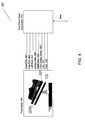
- FIG. 4illustrates a footpedal 103 that may be employed in accordance with the current design.
- the footpedal slave subsystem 105receives one or more control signals from the footpedal 103 .
- the control signals generated by the footpedal 103may report the status of various physical and virtual switches contained within or other parameters such as yaw linear position and vertical linear position.
- the footpedal firmware within the footpedal slave subsystem 105reads and processes the switch inputs.
- the footpedal slave subsystem 105produces a data stream representing control signals resulting from the button and switch positions triggered on the footpedal 103 .
- the control signalsare ultimately destined for the instrument host 120 .
- Control signalsmay include but are not limited to position of a footpedal, such as left heel 403 , center heel 404 , right heel 405 , pitch safety detect 406 , pitch 407 , and yaw 408 positions; button pushes or “stomp” values, or other appropriate states in the case of a footpedal.
- predefined footpedal positions FP 0 , FP 1 , FP 2 , or FP 3 (FPn)may be communicated.
- pitch FP 0 401 and yaw FP 0 402may be communicated when the footpedal slave subsystem becomes connected.
- Control signalsmay be produced by other devices, such as test or monitoring equipment, and these control signals may be transmitted by the multiple channel design presented herein, either separate from or together with the control signals transmitted by the footpedal 103 and communications slave subsystem 107 . Further control signals such as selector switch signals, transducer data, and/or sensor data may be transmitted by the communications slave subsystem 107 to the communications master subsystem 106 . If transmitted separately, the wireless controller 102 and communications master subsystem 107 may receive the transmitted control signals via wireless communications network 130 .
- FIG. 5shows the conceptual connections between the footpedal 103 and the base unit and power source.
- Footpedal 103includes pedal 502 , base 503 , and communications interface 504 here shown at the side of the base 503 .
- the footpedal 103 in this viewincludes batteries 505 , typically rechargeable batteries.
- a transmitter 506 and receiver 507are provided in the footpedal 103 in this embodiment and connect to the communications interface 504 to access the antenna, and in this embodiment a “connection LED” 508 is provided that is constantly on when the both wireless device 101 primary and backup data channels are available for operational use. When either channel becomes disconnected due to interference or other causes, the connection LED 508 may blink on and off, warning the user that one data channel is lost or disconnected and communication redundancy is not available. Blinking in this manner enables the surgeon to decide whether to continue the procedure or wait until the lost data channel is restored.
- Other notification methodsmay be employed, including but not limited to optical (e.g. one LED per channel) and audio notification methods.
Landscapes
- Engineering & Computer Science (AREA)
- Health & Medical Sciences (AREA)
- Life Sciences & Earth Sciences (AREA)
- Computer Networks & Wireless Communication (AREA)
- Signal Processing (AREA)
- Physics & Mathematics (AREA)
- Medical Informatics (AREA)
- Animal Behavior & Ethology (AREA)
- Biomedical Technology (AREA)
- Heart & Thoracic Surgery (AREA)
- Biophysics (AREA)
- Molecular Biology (AREA)
- Surgery (AREA)
- Pathology (AREA)
- General Health & Medical Sciences (AREA)
- Public Health (AREA)
- Veterinary Medicine (AREA)
- Mobile Radio Communication Systems (AREA)
- Electromagnetism (AREA)
- Small-Scale Networks (AREA)
- Transceivers (AREA)
- Arrangements For Transmission Of Measured Signals (AREA)
Abstract
Description
Claims (20)
Priority Applications (11)
| Application Number | Priority Date | Filing Date | Title |
|---|---|---|---|
| US11/250,982US8380126B1 (en) | 2005-10-13 | 2005-10-13 | Reliable communications for wireless devices |
| EP10164058AEP2216913B1 (en) | 2005-10-13 | 2006-10-04 | Reliable communications for wireless devices |
| DE602006018759TDE602006018759D1 (en) | 2005-10-13 | 2006-10-04 | Reliable communication for wireless devices |
| PCT/US2006/038978WO2007047128A1 (en) | 2005-10-13 | 2006-10-04 | Reliable communications for wireless devices |
| AU2006303937AAU2006303937B2 (en) | 2005-10-13 | 2006-10-04 | Reliable communications for wireless devices |
| EP06825502AEP1935110B1 (en) | 2005-10-13 | 2006-10-04 | Reliable communications for wireless devices |
| AT10164058TATE534196T1 (en) | 2005-10-13 | 2006-10-04 | RELIABLE COMMUNICATIONS FOR WIRELESS DEVICES |
| CA2625985ACA2625985C (en) | 2005-10-13 | 2006-10-04 | Reliable communications for wireless devices |
| AT06825502TATE491278T1 (en) | 2005-10-13 | 2006-10-04 | RELIABLE COMMUNICATIONS FOR WIRELESS DEVICES |
| AU2010214703AAU2010214703B2 (en) | 2005-10-13 | 2010-08-27 | Reliable communications for wireless devices |
| US13/765,537US8923768B2 (en) | 2005-10-13 | 2013-02-12 | Reliable communications for wireless devices |
Applications Claiming Priority (1)
| Application Number | Priority Date | Filing Date | Title |
|---|---|---|---|
| US11/250,982US8380126B1 (en) | 2005-10-13 | 2005-10-13 | Reliable communications for wireless devices |
Related Child Applications (1)
| Application Number | Title | Priority Date | Filing Date |
|---|---|---|---|
| US13/765,537ContinuationUS8923768B2 (en) | 2005-10-13 | 2013-02-12 | Reliable communications for wireless devices |
Publications (1)
| Publication Number | Publication Date |
|---|---|
| US8380126B1true US8380126B1 (en) | 2013-02-19 |
Family
ID=37709580
Family Applications (2)
| Application Number | Title | Priority Date | Filing Date |
|---|---|---|---|
| US11/250,982Active2027-10-03US8380126B1 (en) | 2005-10-13 | 2005-10-13 | Reliable communications for wireless devices |
| US13/765,537Expired - LifetimeUS8923768B2 (en) | 2005-10-13 | 2013-02-12 | Reliable communications for wireless devices |
Family Applications After (1)
| Application Number | Title | Priority Date | Filing Date |
|---|---|---|---|
| US13/765,537Expired - LifetimeUS8923768B2 (en) | 2005-10-13 | 2013-02-12 | Reliable communications for wireless devices |
Country Status (7)
| Country | Link |
|---|---|
| US (2) | US8380126B1 (en) |
| EP (2) | EP2216913B1 (en) |
| AT (2) | ATE534196T1 (en) |
| AU (2) | AU2006303937B2 (en) |
| CA (1) | CA2625985C (en) |
| DE (1) | DE602006018759D1 (en) |
| WO (1) | WO2007047128A1 (en) |
Cited By (32)
| Publication number | Priority date | Publication date | Assignee | Title |
|---|---|---|---|---|
| US20110161722A1 (en)* | 2009-12-29 | 2011-06-30 | Tigo Energy | Systems and Methods for a Communication Protocol Between a Local Controller and a Master Controller |
| US20130095766A1 (en)* | 2011-10-14 | 2013-04-18 | Onkyo Corporation | Receiving apparatus |
| US20130169412A1 (en)* | 2011-10-20 | 2013-07-04 | Alcon Research, Ltd. | Haptic Footswitch Treadle |
| US20130317837A1 (en)* | 2012-05-24 | 2013-11-28 | Deka Products Limited Partnership | System, Method, and Apparatus for Electronic Patient Care |
| US20140195639A1 (en)* | 2010-01-22 | 2014-07-10 | Deka Products Limited Partnership | System, Method, and Apparatus for Communicating Data |
| US9007210B2 (en) | 2010-04-22 | 2015-04-14 | Tigo Energy, Inc. | Enhanced system and method for theft prevention in a solar power array during nonoperative periods |
| US9124139B2 (en) | 2010-01-08 | 2015-09-01 | Tigo Energy, Inc. | Systems and methods for an identification protocol between a local controller coupled to control a solar module and a master controller |
| US20150333793A1 (en)* | 2012-12-21 | 2015-11-19 | Hirschmann Automation And Control Gmbh | Method for redundantly and securely transferring data from a data source to a data sink |
| US20160065615A1 (en)* | 2014-08-28 | 2016-03-03 | International Business Machines Corporation | Cloud-based surveillance with intelligent tamper protection |
| US9747760B2 (en)* | 2015-02-10 | 2017-08-29 | International Business Machines Corporation | Safety equipment criteria verification |
| EP3301523A1 (en)* | 2016-09-30 | 2018-04-04 | Siemens Aktiengesellschaft | Redundant operable communications system for an industrial automation system and method of operation |
| US20180214223A1 (en)* | 2014-08-12 | 2018-08-02 | Intuitive Surgical Operations, Inc. | Detecting uncontrolled movement |
| US20190099548A1 (en)* | 2017-10-04 | 2019-04-04 | Abbott Medical Optics Inc. | System, Apparatus and Method for Monitoring Anterior Chamber Intraoperative Intraocular Pressure |
| JP2019526406A (en)* | 2016-08-31 | 2019-09-19 | 北京▲術▼▲鋭▼技▲術▼有限公司Beijing Surgerii Technology Co., Ltd. | Failure detection method for operation support robot operating state |
| US10438697B2 (en)* | 2016-10-25 | 2019-10-08 | General Electric Company | Passive wireless footpedal for medical applications |
| US20190357074A1 (en)* | 2018-05-16 | 2019-11-21 | Comcast Cable Communications, Llc | Systems And Methods For Network Device Management |
| US11210611B2 (en) | 2011-12-21 | 2021-12-28 | Deka Products Limited Partnership | System, method, and apparatus for electronic patient care |
| US11227687B2 (en) | 2010-01-22 | 2022-01-18 | Deka Products Limited Partnership | System, method, and apparatus for communicating data |
| US11244745B2 (en) | 2010-01-22 | 2022-02-08 | Deka Products Limited Partnership | Computer-implemented method, system, and apparatus for electronic patient care |
| US20220116114A1 (en)* | 2018-12-20 | 2022-04-14 | Acacia Communications, Inc. | Side channel communication for an optical coherent transceiver |
| US11383020B2 (en) | 2017-10-04 | 2022-07-12 | Johnson & Johnson Surgical Vision, Inc. | System and method to augment irrigation pressure and to maintain IOP during post occlusion surge |
| US11424029B2 (en) | 2010-01-22 | 2022-08-23 | Deka Products Limited Partnership | System, method and apparatus for electronic patient care |
| US11446424B2 (en) | 2017-10-04 | 2022-09-20 | Johnson & Johnson Surgical Vision, Inc. | Systems and methods for measuring fluid flow in a venturi based system |
| US11524107B2 (en) | 2010-01-22 | 2022-12-13 | Deka Products Limited Partnership | System, method, and apparatus for electronic patient care |
| US11776671B2 (en) | 2010-01-22 | 2023-10-03 | Deka Products Limited Partnership | Electronic patient monitoring system |
| US11969380B2 (en) | 2017-10-04 | 2024-04-30 | Johnson & Johnson Surgical Vision, Inc. | Advanced occlusion management methods for a phacoemulsification system |
| US20240147389A1 (en)* | 2022-10-31 | 2024-05-02 | L3Harris Technologies, Inc. | Radio frequency (rf) communications system having rf nodes that reacquire synchronization lock on spatially diverse, redundant data channels |
| US20240188007A1 (en)* | 2022-10-31 | 2024-06-06 | L3Harris Technologies, Inc. | Radio frequency (rf) communications system having rf nodes that reacquire synchronization lock on frequency diverse, redundant data channels |
| US12098738B2 (en) | 2011-12-21 | 2024-09-24 | Deka Products Limited Partnership | System, method, and apparatus for clamping |
| US12114846B2 (en) | 2018-10-29 | 2024-10-15 | Stryker Corporation | Systems and methods of performing spine surgery and maintaining a volume of fluid at a surgical site |
| US12285360B2 (en) | 2020-12-22 | 2025-04-29 | Johnson & Johnson Surgical Vision, Inc. | Reducing irrigation/aspiration valve response time in a phacoemulsification system |
| US12401583B2 (en) | 2021-10-27 | 2025-08-26 | GE Precision Healthcare LLC | Method and system for monitoring wireless link quality of handheld ultrasound devices |
Families Citing this family (49)
| Publication number | Priority date | Publication date | Assignee | Title |
|---|---|---|---|---|
| US8109885B2 (en) | 2002-03-19 | 2012-02-07 | C. R. Bard, Inc. | Biopsy device for removing tissue specimens using a vacuum |
| EP1524940B1 (en) | 2002-03-19 | 2011-08-24 | Bard Dublin ITC Limited | Biopsy device and biopsy needle module that can be inserted into the biopsy device |
| DE10314240B4 (en) | 2003-03-29 | 2025-05-28 | Bard Dublin Itc Ltd. | Pressure generation unit |
| JP4814229B2 (en) | 2004-07-09 | 2011-11-16 | バード ペリフェラル ヴァスキュラー インコーポレイテッド | Transport device for biopsy device |
| US7517321B2 (en) | 2005-01-31 | 2009-04-14 | C. R. Bard, Inc. | Quick cycle biopsy system |
| ES2539578T3 (en) | 2005-08-10 | 2015-07-02 | C.R. Bard, Inc. | Multi-sample biopsy device and single insert with various transport systems |
| EP1921998B8 (en) | 2005-08-10 | 2021-07-07 | C.R.Bard, Inc. | Single-insertion, multiple sampling biopsy device with linear drive |
| JP4991723B2 (en) | 2005-08-10 | 2012-08-01 | シー・アール・バード・インコーポレーテッド | Single insertion multiple sampling biopsy device with integrated marker |
| EP3417792B1 (en) | 2006-08-21 | 2022-03-02 | C. R. Bard, Inc. | Self-contained handheld biopsy needle |
| SI2086418T1 (en) | 2006-10-06 | 2011-05-31 | Bard Peripheral Vascular Inc | Tissue handling system with reduced operator exposure |
| US8262586B2 (en) | 2006-10-24 | 2012-09-11 | C. R. Bard, Inc. | Large sample low aspect ratio biopsy needle |
| DE102007042389A1 (en) | 2007-09-04 | 2009-03-05 | Carl Zeiss Surgical Gmbh | A method of registering wireless electrical control devices on a medical device |
| US8241225B2 (en) | 2007-12-20 | 2012-08-14 | C. R. Bard, Inc. | Biopsy device |
| US7854706B2 (en) | 2007-12-27 | 2010-12-21 | Devicor Medical Products, Inc. | Clutch and valving system for tetherless biopsy device |
| EP2359354B1 (en)* | 2008-11-22 | 2021-02-24 | WIKA Mobile Control GmbH & Co. KG | Network comprising a control unit and a sensor/actuator with two redundant transmission lines |
| WO2010107424A1 (en) | 2009-03-16 | 2010-09-23 | C.R. Bard, Inc. | Biopsy device having rotational cutting |
| AU2009344276B2 (en) | 2009-04-15 | 2014-06-05 | C.R. Bard, Inc. | Biopsy apparatus having integrated fluid management |
| US8206316B2 (en) | 2009-06-12 | 2012-06-26 | Devicor Medical Products, Inc. | Tetherless biopsy device with reusable portion |
| US9173641B2 (en) | 2009-08-12 | 2015-11-03 | C. R. Bard, Inc. | Biopsy apparatus having integrated thumbwheel mechanism for manual rotation of biopsy cannula |
| US8485989B2 (en) | 2009-09-01 | 2013-07-16 | Bard Peripheral Vascular, Inc. | Biopsy apparatus having a tissue sample retrieval mechanism |
| US8430824B2 (en) | 2009-10-29 | 2013-04-30 | Bard Peripheral Vascular, Inc. | Biopsy driver assembly having a control circuit for conserving battery power |
| US8283890B2 (en) | 2009-09-25 | 2012-10-09 | Bard Peripheral Vascular, Inc. | Charging station for battery powered biopsy apparatus |
| US8597206B2 (en) | 2009-10-12 | 2013-12-03 | Bard Peripheral Vascular, Inc. | Biopsy probe assembly having a mechanism to prevent misalignment of components prior to installation |
| US20110105946A1 (en)* | 2009-10-31 | 2011-05-05 | Sorensen Peter L | Biopsy system with infrared communications |
| CN101777934B (en)* | 2009-12-30 | 2012-11-21 | 三一重工股份有限公司 | Radio link standby system |
| US11164672B2 (en) | 2010-01-22 | 2021-11-02 | Deka Products Limited Partnership | System and apparatus for electronic patient care |
| EP2555668A2 (en) | 2010-04-06 | 2013-02-13 | Koninklijke Philips Electronics N.V. | System and method for highly reliable delivery of life-critical alarms through shared wireless channels |
| CA2902221A1 (en) | 2013-03-20 | 2014-09-25 | Bard Peripheral Vascular, Inc. | Biopsy device |
| ES2726985T3 (en) | 2013-11-05 | 2019-10-11 | Bard Inc C R | Biopsy device that has integrated vacuum |
| DE102014212661A1 (en)* | 2014-06-30 | 2015-12-31 | Trumpf Medizin Systeme Gmbh + Co. Kg | Medical device control system and method for safely operating medical devices through the medical device control system |
| WO2016178656A1 (en) | 2015-05-01 | 2016-11-10 | C. R. Bard, Inc. | Biopsy device |
| US10873538B2 (en)* | 2015-05-05 | 2020-12-22 | Avaya Inc. | Automatic cloud capacity adjustment |
| US10200241B2 (en)* | 2015-05-13 | 2019-02-05 | Stryker Corporation | Method of wireless discovery and networking of medical devices in care environments |
| DE102015212304B4 (en) | 2015-07-01 | 2023-05-17 | Siemens Healthcare Gmbh | X-ray system with a multimodal communication system |
| US10434024B2 (en) | 2016-08-15 | 2019-10-08 | Kavo Dental Technologies, Llc | Modular dental tool and docking station |
| US11844500B2 (en) | 2017-05-19 | 2023-12-19 | Merit Medical Systems, Inc. | Semi-automatic biopsy needle device and methods of use |
| US11793498B2 (en) | 2017-05-19 | 2023-10-24 | Merit Medical Systems, Inc. | Biopsy needle devices and methods of use |
| US11116483B2 (en) | 2017-05-19 | 2021-09-14 | Merit Medical Systems, Inc. | Rotating biopsy needle |
| US10782665B2 (en) | 2017-06-30 | 2020-09-22 | Cattron North America, Inc. | Wireless emergency stop systems, and corresponding methods of operating a wireless emergency stop system for a machine safety interface |
| CA3076901A1 (en) | 2017-09-26 | 2019-04-04 | William F. Wiley | Self-contained ocular surgery instrument |
| GB2568315B (en)* | 2017-11-14 | 2020-06-17 | Cambium Networks Ltd | Fault Tolerant Transmission for a Wireless Link |
| EP3618292B1 (en) | 2018-08-31 | 2023-12-06 | KNORR-BREMSE Systeme für Nutzfahrzeuge GmbH | System and method for establishing an intervehicle communication |
| AU2019363542B2 (en)* | 2018-10-22 | 2023-11-23 | Lazer Safe Pty Ltd | Wireless monitoring/control |
| JP7194846B2 (en)* | 2019-04-18 | 2022-12-22 | シグニファイ ホールディング ビー ヴィ | lighting device |
| US12295556B2 (en) | 2019-09-27 | 2025-05-13 | Merit Medical Systems, Inc. | Rotation biopsy system and handle |
| US12150627B2 (en) | 2019-12-11 | 2024-11-26 | Merit Medical Systems, Inc. | Bone biopsy device and related methods |
| US11487263B2 (en) | 2020-01-24 | 2022-11-01 | Cattron North America, Inc. | Wireless emergency stop systems including mobile device controllers linked with safety stop devices |
| US12046358B2 (en) | 2021-07-22 | 2024-07-23 | Cilag Gmbh International | Configuration of the display settings and displayed information based on the recognition of the user(s) and awareness of procedure, location or usage |
| EP4261862A1 (en)* | 2022-04-11 | 2023-10-18 | Olympus Winter & Ibe GmbH | Medical device with wireless connected foot switch |
Citations (20)
| Publication number | Priority date | Publication date | Assignee | Title |
|---|---|---|---|---|
| US4017828A (en) | 1974-07-19 | 1977-04-12 | Yokogawa Electric Works, Ltd. | Redundancy system for data communication |
| US4983901A (en) | 1989-04-21 | 1991-01-08 | Allergan, Inc. | Digital electronic foot control for medical apparatus and the like |
| US5268624A (en) | 1992-10-14 | 1993-12-07 | Allergan, Inc. | Foot pedal control with user-selectable operational ranges |
| US5388569A (en)* | 1992-09-04 | 1995-02-14 | American Cyanamid Co | Phacoemulsification probe circuit with switch drive |
| US5561575A (en)* | 1995-03-20 | 1996-10-01 | Eways; Michael I. | Foot-controlled operational mechanism for specialized cassette players |
| US20030047434A1 (en)* | 2001-09-07 | 2003-03-13 | Hanson Michael R. | Foot switch pedal controller for a surgical instrument |
| US20030083016A1 (en)* | 2001-10-19 | 2003-05-01 | Koninklijke Philips Electronics N.V. | Method of operating a wireless communication system |
| US20030224729A1 (en)* | 2002-05-28 | 2003-12-04 | Arnold Kenneth David | Interference resistant wireless sensor and control system |
| US20030226091A1 (en) | 2002-05-31 | 2003-12-04 | Scott Platenberg | Redundant path communication methods and systems |
| WO2003102878A1 (en) | 2002-05-31 | 2003-12-11 | Leopold Kostal Gmbh & Co. Kg | Method for controlling user authorization |
| EP1469440A2 (en) | 2003-04-14 | 2004-10-20 | Siemens Aktiengesellschaft | Method for transmission of security information. |
| US20050130098A1 (en)* | 2002-06-17 | 2005-06-16 | Warner Thomas P. | System and method for remotely controlling devices |
| US20050197131A1 (en)* | 1998-02-24 | 2005-09-08 | Kabushiki Kaisha Toshiba | Wireless communication apparatus for selecting frequency channels |
| US20060035585A1 (en)* | 2004-08-16 | 2006-02-16 | Sony Corporation | Distributing apparatus and method for communication using the same |
| US20060046659A1 (en)* | 2004-08-31 | 2006-03-02 | Haartsen Jacobus C | Providing robustness in fading radio channels |
| US7073083B2 (en)* | 2001-07-18 | 2006-07-04 | Thomas Licensing | Method and system for providing emergency shutdown of a malfunctioning device |
| US7103344B2 (en)* | 2000-06-08 | 2006-09-05 | Menard Raymond J | Device with passive receiver |
| US7167723B2 (en)* | 2000-11-27 | 2007-01-23 | Franklin Zhigang Zhang | Dual channel redundant fixed wireless network link, and method therefore |
| US7236766B2 (en)* | 2005-03-31 | 2007-06-26 | Tylu Wireless Technologies, Inc. | Filtered wireless communications |
| US7526038B2 (en)* | 2004-02-27 | 2009-04-28 | Kabushiki Kaisha Toshiba | Communications system, method and device |
Family Cites Families (185)
| Publication number | Priority date | Publication date | Assignee | Title |
|---|---|---|---|---|
| US1848024A (en) | 1931-11-23 | 1932-03-01 | Norris T Owen | Apparatus for use in blood transfusion, intravenous medication and the like |
| NL113902C (en) | 1958-08-29 | 1900-01-01 | ||
| US3116697A (en) | 1962-08-23 | 1964-01-07 | Technicon Instr | Compressible tube type fluid pump |
| US3439680A (en) | 1965-04-12 | 1969-04-22 | Univ Northwestern | Surgical instrument for cataract removal |
| US3526219A (en) | 1967-07-21 | 1970-09-01 | Ultrasonic Systems | Method and apparatus for ultrasonically removing tissue from a biological organism |
| US3781142A (en) | 1972-01-14 | 1973-12-25 | Flow Technology Corp | Peristalic pump with adjustable tensioning means |
| US3857387A (en) | 1972-12-26 | 1974-12-31 | Ultrasonic Systems | Ultrasonic cataract removal method and apparatus |
| US4037491A (en) | 1976-05-20 | 1977-07-26 | Newbold Zebbie J | Sewing machine foot switch operating device |
| US4189286A (en) | 1977-03-15 | 1980-02-19 | Fibra-Sonics, Inc. | Peristaltic pump |
| US4193004A (en) | 1978-06-22 | 1980-03-11 | Cobe Laboratories, Inc. | Fluid level monitoring through fluid cell protrusion |
| SE8100044L (en) | 1981-01-07 | 1982-07-08 | Vitrum Ab | PUMP |
| US4590934A (en) | 1983-05-18 | 1986-05-27 | Jerry L. Malis | Bipolar cutter/coagulator |
| DE3326786A1 (en) | 1983-07-25 | 1985-02-14 | Fresenius AG, 6380 Bad Homburg | PUMP BED FOR A ROLL PUMP |
| US4757814A (en) | 1985-02-28 | 1988-07-19 | Alcon Laboratories, Inc. | Proportional control for pneumatic cutting device |
| US4706687A (en) | 1985-02-28 | 1987-11-17 | Alcon Instrumentation, Inc. | Linear suction control system |
| US4665621A (en) | 1986-03-31 | 1987-05-19 | Jerome B. Ackerman | Measuring probe |
| US4837857A (en) | 1986-11-06 | 1989-06-06 | Storz Instrument Company | Foot pedal assembly for ophthalmic surgical instrument |
| US4933843A (en) | 1986-11-06 | 1990-06-12 | Storz Instrument Company | Control system for ophthalmic surgical instruments |
| US4773897A (en) | 1986-11-06 | 1988-09-27 | Storz Instrument Company | Collection container for ophthalmic surgical system |
| US4954960A (en) | 1986-11-07 | 1990-09-04 | Alcon Laboratories | Linear power control for ultrasonic probe with tuned reactance |
| US5125891A (en) | 1987-04-27 | 1992-06-30 | Site Microsurgical Systems, Inc. | Disposable vacuum/peristaltic pump cassette system |
| US5195960A (en) | 1987-04-27 | 1993-03-23 | Site Microsurgical Systems, Inc. | Disposable vacuum/peristaltic pump cassette system |
| US5006110A (en) | 1987-12-01 | 1991-04-09 | Pacesetter Infusion, Ltd. | Air-in-line detector infusion system |
| WO1993012743A1 (en) | 1988-04-20 | 1993-07-08 | Susumu Takahashi | Suction apparatus |
| US4998972A (en) | 1988-04-28 | 1991-03-12 | Thomas J. Fogarty | Real time angioscopy imaging system |
| US4920336A (en) | 1988-11-22 | 1990-04-24 | Fisher Scientific Company | Method and apparatus for monitoring the level of the contents in a container |
| US5163900A (en) | 1989-03-16 | 1992-11-17 | Surgin Surgical Instrumentation, Inc. | Disposable cassette systems |
| US4965417A (en) | 1989-03-27 | 1990-10-23 | Massie Philip E | Foot-operated control |
| GB2230301A (en) | 1989-04-07 | 1990-10-17 | Unilever Plc | Adjustable peristaltic pump |
| US5249121A (en) | 1989-10-27 | 1993-09-28 | American Cyanamid Company | Remote control console for surgical control system |
| US5091656A (en) | 1989-10-27 | 1992-02-25 | Storz Instrument Company | Footswitch assembly with electrically engaged detents |
| US5039973A (en) | 1990-02-05 | 1991-08-13 | Carballo Rodolfo A | Electronic foot pedal controller with booster power for universal motors |
| US5026387A (en) | 1990-03-12 | 1991-06-25 | Ultracision Inc. | Method and apparatus for ultrasonic surgical cutting and hemostatis |
| US5160317A (en) | 1991-01-03 | 1992-11-03 | Costin John A | Computer controlled smart phacoemulsification method and apparatus |
| WO1992020310A1 (en) | 1991-05-10 | 1992-11-26 | Ophthalmocare, Inc. | Phaco handpiece providing fingertip control of ultrasonic energy |
| US5271379A (en) | 1991-07-26 | 1993-12-21 | The Regents Of The University Of California | Endoscopic device actuator and method |
| AU2366092A (en) | 1991-07-31 | 1993-03-02 | Mentor O&O, Inc. | Controlling operation of handpieces during ophthalmic surgery |
| CA2078295C (en) | 1991-08-05 | 1995-11-21 | John Michael Putman | Endoscope stabilizer |
| US5195971A (en) | 1992-02-10 | 1993-03-23 | Advanced Cardiovascular Systems, Inc. | Perfusion type dilatation catheter |
| WO1993017729A1 (en) | 1992-03-03 | 1993-09-16 | Alcon Surgical, Inc. | System and apparatus for controlling fluid flow from a surgical handpiece |
| WO1993024082A1 (en) | 1992-06-03 | 1993-12-09 | Allergan, Inc. | Tubing management system |
| US5230614A (en) | 1992-06-03 | 1993-07-27 | Allergan, Inc. | Reduced pulsation tapered ramp pump head |
| US5323543A (en) | 1992-09-29 | 1994-06-28 | Keratron Group | Apparatus and method for calibrating a surgical knife |
| US5354268A (en) | 1992-11-04 | 1994-10-11 | Medical Instrument Development Laboratories, Inc. | Methods and apparatus for control of vacuum and pressure for surgical procedures |
| EP0888788A1 (en) | 1992-11-06 | 1999-01-07 | GRIESHABER & CO. AG SCHAFFHAUSEN | Plug-in unit for ophthalmic device |
| EP0619993B1 (en) | 1993-03-12 | 1997-07-02 | Selig Percy Amoils | A surgical instrument for use in opthalmic surgery |
| US6368269B1 (en) | 1993-05-20 | 2002-04-09 | Tilane Corporation | Apparatus for concurrent actuation of multiple foot pedal operated switches |
| US5342293A (en) | 1993-06-22 | 1994-08-30 | Allergan, Inc. | Variable vacuum/variable flow phacoemulsification method |
| DE4327152C2 (en) | 1993-08-12 | 1995-10-19 | Stoeckert Instr Gmbh | Roller pump |
| US5591127A (en) | 1994-01-28 | 1997-01-07 | Barwick, Jr.; Billie J. | Phacoemulsification method and apparatus |
| JP3610595B2 (en) | 1994-07-20 | 2005-01-12 | 松下電器産業株式会社 | Cordless telephone equipment |
| DE9412228U1 (en) | 1994-07-28 | 1994-09-22 | Loctite Europa E.E.I.G. (E.W.I.V.), 85748 Garching | Peristaltic pump for precise dosing of small amounts of liquid |
| US5554894A (en) | 1994-10-28 | 1996-09-10 | Iolab Corporation | Electronic footswitch for ophthalmic surgery |
| EP0717970A1 (en) | 1994-12-20 | 1996-06-26 | GRIESHABER & CO. AG SCHAFFHAUSEN | Opthalmic aspiration and irrigation device and its operation procedure |
| DE19501581C2 (en) | 1995-01-20 | 1998-08-27 | Huettinger Medtech Gmbh | Operating device for medical-technical system workplaces |
| US5569188A (en) | 1995-04-11 | 1996-10-29 | Mackool; Richard J. | Apparatus for controlling fluid flow through a surgical instrument and the temperature of an ultrasonic instrument |
| US5657000A (en) | 1995-06-02 | 1997-08-12 | Cobe Laboratories, Inc. | Peristaltic pump occlusion detector and adjuster |
| JPH0929989A (en) | 1995-07-14 | 1997-02-04 | Canon Inc | Ink presence detection device, ink tank, kit, recording unit, recording device, and information processing system |
| US5549461A (en) | 1995-07-21 | 1996-08-27 | Newland; George | Peristaltic pump attachment for slurry mixers |
| FR2737261B1 (en) | 1995-07-27 | 1997-10-10 | Jean Francois Ognier | PERISTALTIC PUMP |
| US5745647A (en) | 1995-09-15 | 1998-04-28 | Smith & Nephew, Inc. | Method and apparatus for automatically controlling and scaling motor velocity |
| US5883615A (en) | 1995-09-29 | 1999-03-16 | Liebel-Flarsheim Company | Foot-operated control system for a multi-function |
| US5899674A (en) | 1995-12-01 | 1999-05-04 | Alcon Laboratories, Inc. | Indentification system for a surgical cassette |
| US6219032B1 (en) | 1995-12-01 | 2001-04-17 | Immersion Corporation | Method for providing force feedback to a user of an interface device based on interactions of a controlled cursor with graphical elements in a graphical user interface |
| CA2186805C (en) | 1995-12-01 | 2001-03-27 | Christopher C. Jung | Apparatus and method for sensing fluid level |
| US5830176A (en) | 1995-12-26 | 1998-11-03 | Mackool; Richard J. | Maintenance of pressure within a surgical site during a surgical procedure |
| US5676530A (en) | 1996-01-24 | 1997-10-14 | Alcon Laboratories, Inc. | Surgical cassette latching mechanism |
| US5843109A (en) | 1996-05-29 | 1998-12-01 | Allergan | Ultrasonic handpiece with multiple piezoelectric elements and heat dissipator |
| US5697898A (en) | 1996-05-31 | 1997-12-16 | Surgical Design Corporation | Automated free flow mechanism for use in phacoemulsification, irrigation and aspiration of the eye |
| DE19624517C1 (en) | 1996-06-19 | 1997-11-13 | Siemens Ag | Control unit for medical device e.g. magnetron open or MR guided processor package |
| DE69731472T2 (en) | 1996-08-15 | 2005-10-20 | Deka Products Ltd. Partnership | PUMP AND SYSTEM FOR MEDICAL IRRIGATION |
| DE69728793T2 (en) | 1996-08-29 | 2004-09-23 | Bausch & Lomb Surgical, Inc. | FREQUENCY AND POWER CONTROL ARRANGEMENT WITH DOUBLE CIRCLE |
| US6117126A (en) | 1996-08-29 | 2000-09-12 | Bausch & Lomb Surgical, Inc. | Surgical module with independent microprocessor-based communication |
| US6251113B1 (en) | 1996-08-29 | 2001-06-26 | Bausch & Lomb Surgical, Inc. | Ophthalmic microsurgical system employing surgical module employing flash EEPROM and reprogrammable modules |
| US6086598A (en) | 1996-08-29 | 2000-07-11 | Bausch & Lomb Surgical, Inc. | Ophthalmic microsurgical system having color sensor for cassette identification |
| US5792167A (en) | 1996-09-13 | 1998-08-11 | Stryker Corporation | Surgical irrigation pump and tool system |
| US5733256A (en) | 1996-09-26 | 1998-03-31 | Micro Medical Devices | Integrated phacoemulsification system |
| US5746719A (en) | 1996-10-25 | 1998-05-05 | Arthur D. Little, Inc. | Fluid flow control system incorporating a disposable pump cartridge |
| US7169123B2 (en) | 1997-01-22 | 2007-01-30 | Advanced Medical Optics, Inc. | Control of pulse duty cycle based upon footswitch displacement |
| US6780165B2 (en) | 1997-01-22 | 2004-08-24 | Advanced Medical Optics | Micro-burst ultrasonic power delivery |
| US6179829B1 (en) | 1997-08-28 | 2001-01-30 | Bausch & Lomb Surgical, Inc. | Foot controller for microsurgical system |
| US5983749A (en) | 1997-09-12 | 1999-11-16 | Allergan Sales, Inc. | Dual position foot pedal for ophthalmic surgery apparatus |
| US6036458A (en) | 1997-10-03 | 2000-03-14 | Allergan Sales, Inc. | Automated phaco pack bar code reader identification |
| GB9721008D0 (en) | 1997-10-03 | 1997-12-03 | Hewlett Packard Co | Power management method foruse in a wireless local area network (LAN) |
| US6169387B1 (en) | 1997-12-22 | 2001-01-02 | Lifecor, Inc. | Battery management apparatus for portable electronic devices |
| US6986753B2 (en) | 1998-05-21 | 2006-01-17 | Buivision | Constant ocular pressure active infusion system |
| US6511454B1 (en) | 1998-05-29 | 2003-01-28 | Nidek Co., Ltd. | Irrigation/aspiration apparatus and irrigation/aspiration cassette therefore |
| US6077285A (en) | 1998-06-29 | 2000-06-20 | Alcon Laboratories, Inc. | Torsional ultrasound handpiece |
| EP1010437A1 (en) | 1998-06-30 | 2000-06-21 | Nidek Co., Ltd. | Irrigation/aspiration apparatus |
| US6150623A (en) | 1998-08-27 | 2000-11-21 | Allergan | Back-flip medical footpedal |
| US6358237B1 (en) | 1999-01-19 | 2002-03-19 | Assistive Technology Products, Inc. | Methods and apparatus for delivering fluids to a patient |
| JP2002544439A (en) | 1999-05-12 | 2002-12-24 | ジー. ジョン アンデルセン, | Peristaltic pump |
| CA2275041C (en) | 1999-06-17 | 2008-01-22 | Vtech Communications, Ltd. | Method and apparatus of extending useful life of a cordless telephone during a power outage condition |
| US6002484A (en) | 1999-06-18 | 1999-12-14 | Rozema; Jos J. | Phase contrast aberroscope |
| US6179808B1 (en) | 1999-06-18 | 2001-01-30 | Alcon Laboratories, Inc. | Method of controlling the operating parameters of a surgical system |
| US6261283B1 (en) | 1999-08-31 | 2001-07-17 | Alcon Universal Ltd. | Liquid venting surgical system and cassette |
| US6962488B2 (en) | 1999-11-10 | 2005-11-08 | Alcon, Inc. | Surgical cassette having an aspiration pressure sensor |
| US6411062B1 (en) | 1999-09-21 | 2002-06-25 | Sony Corporation | Quick release battery and clip for portable device and method of implementing same |
| JP3539326B2 (en) | 1999-12-27 | 2004-07-07 | 日本電気株式会社 | Mobile device charging system |
| JP3935653B2 (en) | 2000-02-04 | 2007-06-27 | 株式会社ニデック | Perfusion suction device |
| US6984220B2 (en) | 2000-04-12 | 2006-01-10 | Wuchinich David G | Longitudinal-torsional ultrasonic tissue dissection |
| US6452120B1 (en) | 2000-05-11 | 2002-09-17 | Advanced Medical Optics | Dual dimensional shoe sensor and foot pedal operated switch for surgical control |
| US6452123B1 (en) | 2000-06-27 | 2002-09-17 | Advanced Medical Optics | Surgical foot pedal control including ribbon switch arrangement |
| US6561999B1 (en) | 2000-09-29 | 2003-05-13 | Alcon Universal Ltd. | Surgical cassette and consumables for combined ophthalmic surgical procedure |
| CA2416555C (en) | 2000-10-17 | 2008-05-20 | Alcon, Inc. | Mappable foot controller for microsurgical system |
| US6468241B1 (en) | 2000-10-26 | 2002-10-22 | Chf Solutions, Inc. | Artificial kidney set with electronic key |
| DE10057589C1 (en) | 2000-11-21 | 2002-07-11 | Erbe Elektromedizin | footswitch |
| DE10062600C2 (en) | 2000-12-12 | 2002-12-05 | Wom World Of Medicine Ag | Peristaltic peristaltic pump |
| JP3528799B2 (en) | 2001-01-24 | 2004-05-24 | 日本電気株式会社 | Terminal device, terminal monitoring system, and terminal monitoring method |
| DE10114333B4 (en) | 2001-03-23 | 2006-02-16 | Ferton Holding S.A. | footswitch |
| US6745895B2 (en) | 2001-06-01 | 2004-06-08 | Brian Silvers | Diaper caddy |
| EP1400096B1 (en) | 2001-06-28 | 2013-07-31 | Gigaset Communications GmbH | Logging in of battery-operated mobile parts in base stations with a battery charging device |
| US6674030B2 (en) | 2001-09-19 | 2004-01-06 | Advanced Medical Optics | Intelligent surgical footpedal with low noise, low resistance vibration feedback |
| US6830555B2 (en) | 2001-10-09 | 2004-12-14 | Advanced Medical Optics | Multi-functional second instrument for cataract removal |
| US7470277B2 (en) | 2001-10-16 | 2008-12-30 | Alcon, Inc. | Simultaneous proportional control of surgical parameters in a microsurgical system |
| ITRM20010669A1 (en) | 2001-11-09 | 2003-05-09 | Optikon 2000 Spa | SUCTION INFUSION BOX (I / A) WITH SUCTION SYSTEM BOTH VIA PERISTALTIC PUMP OR OTHERWISE VOLUMETRIC THAN USING PR PUMP |
| EP1453432B1 (en) | 2001-12-04 | 2012-08-01 | Tyco Healthcare Group LP | System and method for calibrating a surgical instrument |
| US7070578B2 (en) | 2002-04-25 | 2006-07-04 | Alcon, Inc. | Surgical cassette latching mechanism |
| US7242765B2 (en) | 2002-06-28 | 2007-07-10 | Tommy Lee Hairston | Headset cellular telephones |
| US6862951B2 (en) | 2002-08-26 | 2005-03-08 | Alcon, Inc. | Footswitch |
| US6852092B2 (en) | 2002-10-02 | 2005-02-08 | Advanced Medical Optics, Inc. | Handpiece system for multiple phacoemulsification techniques |
| US7316664B2 (en) | 2002-10-21 | 2008-01-08 | Advanced Medical Optics, Inc. | Modulated pulsed ultrasonic power delivery system and method |
| US6962581B2 (en) | 2002-12-03 | 2005-11-08 | Alcon, Inc. | Foot controller for microsurgical system |
| JP4162544B2 (en) | 2003-01-15 | 2008-10-08 | 株式会社ニデック | Ultrasonic surgical device |
| US7570994B2 (en) | 2003-04-25 | 2009-08-04 | Medtronic Physio-Control Corp. | Apparatus and method for maintaining a defibrillator battery charge and optionally communicating |
| WO2004110524A2 (en) | 2003-06-06 | 2004-12-23 | Phacor, Inc. | Fluid-flow cassette for an ophthalmic surgical instrument |
| US8147406B2 (en) | 2003-06-18 | 2012-04-03 | Panasonic Corporation | Biological information utilization system, biological information utilization method, program, and recording medium |
| US7846126B2 (en) | 2003-07-14 | 2010-12-07 | Abbott Medical Optics, Inc. | System and method for modulated surgical procedure irrigation and aspiration |
| US7300264B2 (en) | 2003-09-08 | 2007-11-27 | Hewlett-Packard Development, L.P. | Peristaltic pump |
| US7604607B2 (en) | 2003-09-29 | 2009-10-20 | Bausch & Lomb Incorporated | Peristaltic pump fitment for attachment to an aspirant collection bag |
| US7168930B2 (en) | 2003-09-29 | 2007-01-30 | Bausch & Lomb Incorporated | Peristaltic pump with air venting via the movement of a pump head or a backing plate during surgery |
| US7193169B2 (en) | 2003-10-29 | 2007-03-20 | Alcon, Inc. | Ergonomic footswitch |
| JP4290531B2 (en) | 2003-11-14 | 2009-07-08 | 京セラ株式会社 | Portable telephone equipment |
| KR101230661B1 (en) | 2004-03-05 | 2013-02-06 | 퓨처 메디칼 시스템 에스.에이. | Cassette for irrigation or aspiration machine for endoscopy |
| US7289825B2 (en) | 2004-03-15 | 2007-10-30 | General Electric Company | Method and system for utilizing wireless voice technology within a radiology workflow |
| US7651490B2 (en) | 2004-08-12 | 2010-01-26 | Alcon, Inc. | Ultrasonic handpiece |
| US7811255B2 (en) | 2004-03-22 | 2010-10-12 | Alcon, Inc. | Method of controlling a surgical system based on a rate of change of an operating parameter |
| US7625388B2 (en) | 2004-03-22 | 2009-12-01 | Alcon, Inc. | Method of controlling a surgical system based on a load on the cutting tip of a handpiece |
| US20050245888A1 (en) | 2004-04-29 | 2005-11-03 | Cull Laurence J | Combined peristaltic and vacuum aspiration cassette |
| US20060078448A1 (en) | 2004-10-11 | 2006-04-13 | Holden Hugo R | Phacoemulsification machine with post-occlusion surge control system and related method |
| US20060145540A1 (en) | 2004-11-12 | 2006-07-06 | Mezhinsky Victor B | Dual linear control footswitch |
| US7945341B2 (en) | 2004-11-30 | 2011-05-17 | Alcon, Inc. | Graphical user interface for selecting pulse parameters in a phacoemulsification surgical system |
| ES2264369B1 (en) | 2005-02-25 | 2008-01-16 | Jose Luis Orts Doñate | MULTIFUNCTION PEDAL. |
| US7785316B2 (en) | 2005-03-21 | 2010-08-31 | Abbott Medical Optics Inc. | Application of a system parameter as a method and mechanism for controlling eye chamber stability |
| US7670330B2 (en) | 2005-03-21 | 2010-03-02 | Abbott Medical Optics Inc. | Application of vacuum as a method and mechanism for controlling eye chamber stability |
| CA2803828C (en) | 2005-03-31 | 2015-11-24 | Alcon, Inc. | Footswitch operable to control a surgical system |
| EP1883793A1 (en) | 2005-05-27 | 2008-02-06 | Opto Global Holdings Pty Ltd. | System and method for laser calibration |
| US7604615B2 (en) | 2006-03-20 | 2009-10-20 | Alcon, Inc. | Surgical cassette with bubble separating structure |
| US20070005002A1 (en) | 2005-06-30 | 2007-01-04 | Intuitive Surgical Inc. | Robotic surgical instruments for irrigation, aspiration, and blowing |
| US20070078379A1 (en) | 2005-08-31 | 2007-04-05 | Alcon, Inc. | Controlling a phacoemulsification surgical system by transitioning between pulse and burst modes |
| US8016843B2 (en) | 2005-09-09 | 2011-09-13 | Alcon Research Ltd | Ultrasonic knife |
| US8011905B2 (en) | 2005-11-17 | 2011-09-06 | Novartis Ag | Surgical cassette |
| US7439463B2 (en) | 2006-01-17 | 2008-10-21 | Dentsply International Inc. | Foot switch for activating a dental or medical treatment apparatus |
| US20070249942A1 (en) | 2006-04-21 | 2007-10-25 | Alcon, Inc. | System for driving an ultrasonic handpiece with a class D amplifier |
| US20070249941A1 (en) | 2006-04-21 | 2007-10-25 | Alcon, Inc. | Method for driving an ultrasonic handpiece with a class D amplifier |
| US8303542B2 (en) | 2006-06-10 | 2012-11-06 | Bausch & Lomb Incorporated | Ophthalmic surgical cassette and system |
| US7712802B2 (en) | 2006-06-12 | 2010-05-11 | Alcon, Inc. | Cassette clamping mechanism |
| EP2034936A4 (en) | 2006-06-16 | 2012-01-25 | Holden Jeannette | Control flow device |
| US7786457B2 (en) | 2006-06-28 | 2010-08-31 | Alcon, Inc. | Systems and methods of non-invasive level sensing for a surgical cassette |
| US7921017B2 (en) | 2006-07-20 | 2011-04-05 | Abbott Medical Optics Inc | Systems and methods for voice control of a medical device |
| US20080146989A1 (en) | 2006-07-30 | 2008-06-19 | Jaime Zacharias | Anti-repulsion anti-clogging system and method for driving a dual-axis lensectomy probe |
| US7785336B2 (en) | 2006-08-01 | 2010-08-31 | Abbott Medical Optics Inc. | Vacuum sense control for phaco pulse shaping |
| US8652086B2 (en) | 2006-09-08 | 2014-02-18 | Abbott Medical Optics Inc. | Systems and methods for power and flow rate control |
| US8465467B2 (en) | 2006-09-14 | 2013-06-18 | Novartis Ag | Method of controlling an irrigation/aspiration system |
| US7381917B2 (en) | 2006-09-20 | 2008-06-03 | Alcon, Inc. | Footswitch assembly with position memory |
| US10959881B2 (en) | 2006-11-09 | 2021-03-30 | Johnson & Johnson Surgical Vision, Inc. | Fluidics cassette for ocular surgical system |
| US7967777B2 (en) | 2006-11-09 | 2011-06-28 | Abbott Medical Optics Inc. | Eye treatment system with multiple pumps |
| WO2008060995A1 (en) | 2006-11-09 | 2008-05-22 | Advanced Medical Optics, Inc. | Reversible peristaltic pump and other structures for reflux in eye surgery |
| US9033940B2 (en) | 2006-11-09 | 2015-05-19 | Abbott Medical Optics Inc. | Eye treatment system with fluidics pump interface |
| US8491528B2 (en) | 2006-11-09 | 2013-07-23 | Abbott Medical Optics Inc. | Critical alignment of fluidics cassettes |
| US9295765B2 (en) | 2006-11-09 | 2016-03-29 | Abbott Medical Optics Inc. | Surgical fluidics cassette supporting multiple pumps |
| US9522221B2 (en) | 2006-11-09 | 2016-12-20 | Abbott Medical Optics Inc. | Fluidics cassette for ocular surgical system |
| US20080114387A1 (en) | 2006-11-10 | 2008-05-15 | Hertweck David W | Dual linear ultrasound control |
| JP2008188110A (en) | 2007-02-01 | 2008-08-21 | Olympus Medical Systems Corp | Surgical microscope foot switch |
| US8465473B2 (en) | 2007-03-28 | 2013-06-18 | Novartis Ag | Surgical footswitch with movable shroud |
| US9050123B2 (en) | 2007-04-16 | 2015-06-09 | Smith & Nephew, Inc. | Powered surgical system |
| US8303530B2 (en) | 2007-05-10 | 2012-11-06 | Novartis Ag | Method of operating an ultrasound handpiece |
| US10485699B2 (en) | 2007-05-24 | 2019-11-26 | Johnson & Johnson Surgical Vision, Inc. | Systems and methods for transverse phacoemulsification |
| US10596032B2 (en) | 2007-05-24 | 2020-03-24 | Johnson & Johnson Surgical Vision, Inc. | System and method for controlling a transverse phacoemulsification system with a footpedal |
| US20090005789A1 (en) | 2007-06-26 | 2009-01-01 | Charles Steven T | Force Sensitive Foot Controller |
| US10349925B2 (en) | 2008-11-07 | 2019-07-16 | Johnson & Johnson Surgical Vision, Inc. | Method for programming foot pedal settings and controlling performance through foot pedal variation |
| AU2009313402C1 (en) | 2008-11-07 | 2015-10-15 | Johnson & Johnson Surgical Vision, Inc. | Automatically switching different aspiration levels and/or pumps to an ocular probe |
| EP2373265B1 (en) | 2008-11-07 | 2016-03-09 | Abbott Medical Optics Inc. | Controlling of multiple pumps |
| EP2341878B1 (en) | 2008-11-07 | 2017-06-21 | Abbott Medical Optics Inc. | Semi-automatic device calibraton |
| EP3156012B1 (en) | 2008-11-07 | 2021-10-20 | Johnson & Johnson Surgical Vision, Inc. | Adjustable foot pedal control for ophthalmic surgery |
- 2005
- 2005-10-13USUS11/250,982patent/US8380126B1/enactiveActive
- 2006
- 2006-10-04WOPCT/US2006/038978patent/WO2007047128A1/enactiveApplication Filing
- 2006-10-04DEDE602006018759Tpatent/DE602006018759D1/enactiveActive
- 2006-10-04ATAT10164058Tpatent/ATE534196T1/enactive
- 2006-10-04CACA2625985Apatent/CA2625985C/ennot_activeExpired - Fee Related
- 2006-10-04AUAU2006303937Apatent/AU2006303937B2/ennot_activeCeased
- 2006-10-04ATAT06825502Tpatent/ATE491278T1/ennot_activeIP Right Cessation
- 2006-10-04EPEP10164058Apatent/EP2216913B1/ennot_activeNot-in-force
- 2006-10-04EPEP06825502Apatent/EP1935110B1/ennot_activeNot-in-force
- 2010
- 2010-08-27AUAU2010214703Apatent/AU2010214703B2/ennot_activeCeased
- 2013
- 2013-02-12USUS13/765,537patent/US8923768B2/ennot_activeExpired - Lifetime
Patent Citations (21)
| Publication number | Priority date | Publication date | Assignee | Title |
|---|---|---|---|---|
| US4017828A (en) | 1974-07-19 | 1977-04-12 | Yokogawa Electric Works, Ltd. | Redundancy system for data communication |
| US4983901A (en) | 1989-04-21 | 1991-01-08 | Allergan, Inc. | Digital electronic foot control for medical apparatus and the like |
| US5388569A (en)* | 1992-09-04 | 1995-02-14 | American Cyanamid Co | Phacoemulsification probe circuit with switch drive |
| US5268624A (en) | 1992-10-14 | 1993-12-07 | Allergan, Inc. | Foot pedal control with user-selectable operational ranges |
| US5561575A (en)* | 1995-03-20 | 1996-10-01 | Eways; Michael I. | Foot-controlled operational mechanism for specialized cassette players |
| US20050197131A1 (en)* | 1998-02-24 | 2005-09-08 | Kabushiki Kaisha Toshiba | Wireless communication apparatus for selecting frequency channels |
| US7103344B2 (en)* | 2000-06-08 | 2006-09-05 | Menard Raymond J | Device with passive receiver |
| US7167723B2 (en)* | 2000-11-27 | 2007-01-23 | Franklin Zhigang Zhang | Dual channel redundant fixed wireless network link, and method therefore |
| US7073083B2 (en)* | 2001-07-18 | 2006-07-04 | Thomas Licensing | Method and system for providing emergency shutdown of a malfunctioning device |
| US20030047434A1 (en)* | 2001-09-07 | 2003-03-13 | Hanson Michael R. | Foot switch pedal controller for a surgical instrument |
| US20030083016A1 (en)* | 2001-10-19 | 2003-05-01 | Koninklijke Philips Electronics N.V. | Method of operating a wireless communication system |
| US20030224729A1 (en)* | 2002-05-28 | 2003-12-04 | Arnold Kenneth David | Interference resistant wireless sensor and control system |
| WO2003102878A1 (en) | 2002-05-31 | 2003-12-11 | Leopold Kostal Gmbh & Co. Kg | Method for controlling user authorization |
| US20030226091A1 (en) | 2002-05-31 | 2003-12-04 | Scott Platenberg | Redundant path communication methods and systems |
| US20050130098A1 (en)* | 2002-06-17 | 2005-06-16 | Warner Thomas P. | System and method for remotely controlling devices |
| EP1469440A2 (en) | 2003-04-14 | 2004-10-20 | Siemens Aktiengesellschaft | Method for transmission of security information. |
| US20040224641A1 (en) | 2003-04-14 | 2004-11-11 | Siemens Aktiengesellschaft | Method for transmitting safety related data |
| US7526038B2 (en)* | 2004-02-27 | 2009-04-28 | Kabushiki Kaisha Toshiba | Communications system, method and device |
| US20060035585A1 (en)* | 2004-08-16 | 2006-02-16 | Sony Corporation | Distributing apparatus and method for communication using the same |
| US20060046659A1 (en)* | 2004-08-31 | 2006-03-02 | Haartsen Jacobus C | Providing robustness in fading radio channels |
| US7236766B2 (en)* | 2005-03-31 | 2007-06-26 | Tylu Wireless Technologies, Inc. | Filtered wireless communications |
Non-Patent Citations (2)
| Title |
|---|
| Merritt Rick, "Wireless nets starting to link medical gear, http://www.eetimes.com/showArticle.jht ml?articleID=17200448 [retrieved on Feb. 12, 2007,XP002419686," EETIMES, 2004. |
| Merritt, Rick: "Wireless nets starting to link medical gear," EETIMES, Jan. 7, 2004; one page, XP-002419686; Retrieved form the internet: www.eetimes.com/showArticle; retrieved Feb. 12, 2007. |
Cited By (58)
| Publication number | Priority date | Publication date | Assignee | Title |
|---|---|---|---|---|
| US8773236B2 (en)* | 2009-12-29 | 2014-07-08 | Tigo Energy, Inc. | Systems and methods for a communication protocol between a local controller and a master controller |
| US20110161722A1 (en)* | 2009-12-29 | 2011-06-30 | Tigo Energy | Systems and Methods for a Communication Protocol Between a Local Controller and a Master Controller |
| US9124139B2 (en) | 2010-01-08 | 2015-09-01 | Tigo Energy, Inc. | Systems and methods for an identification protocol between a local controller coupled to control a solar module and a master controller |
| US10135385B2 (en) | 2010-01-08 | 2018-11-20 | Tigo Energy, Inc. | Identification protocol between a local controller of a solar module and a master controller |
| US10749457B2 (en) | 2010-01-08 | 2020-08-18 | Tigo Energy, Inc. | Systems and methods for an identification protocol between a local controller of a solar module and a master controller |
| US20140195639A1 (en)* | 2010-01-22 | 2014-07-10 | Deka Products Limited Partnership | System, Method, and Apparatus for Communicating Data |
| US11227687B2 (en) | 2010-01-22 | 2022-01-18 | Deka Products Limited Partnership | System, method, and apparatus for communicating data |
| US11810653B2 (en) | 2010-01-22 | 2023-11-07 | Deka Products Limited Partnership | Computer-implemented method, system, and apparatus for electronic patient care |
| US11244745B2 (en) | 2010-01-22 | 2022-02-08 | Deka Products Limited Partnership | Computer-implemented method, system, and apparatus for electronic patient care |
| US10044791B2 (en)* | 2010-01-22 | 2018-08-07 | Deka Products Limited Partnership | System, method, and apparatus for communicating data |
| US11424029B2 (en) | 2010-01-22 | 2022-08-23 | Deka Products Limited Partnership | System, method and apparatus for electronic patient care |
| US11524107B2 (en) | 2010-01-22 | 2022-12-13 | Deka Products Limited Partnership | System, method, and apparatus for electronic patient care |
| US12070572B2 (en) | 2010-01-22 | 2024-08-27 | Deka Products Limited Partnership | System, method, and apparatus for electronic patient care |
| US11776671B2 (en) | 2010-01-22 | 2023-10-03 | Deka Products Limited Partnership | Electronic patient monitoring system |
| US11830617B2 (en) | 2010-01-22 | 2023-11-28 | Deka Products Limited Partneship | System, method, and apparatus for communicating data |
| US9007210B2 (en) | 2010-04-22 | 2015-04-14 | Tigo Energy, Inc. | Enhanced system and method for theft prevention in a solar power array during nonoperative periods |
| US8781406B2 (en)* | 2011-10-14 | 2014-07-15 | Onkyo Corporation | Receiving apparatus |
| US20130095766A1 (en)* | 2011-10-14 | 2013-04-18 | Onkyo Corporation | Receiving apparatus |
| US9240110B2 (en)* | 2011-10-20 | 2016-01-19 | Alcon Research, Ltd. | Haptic footswitch treadle |
| US20130169412A1 (en)* | 2011-10-20 | 2013-07-04 | Alcon Research, Ltd. | Haptic Footswitch Treadle |
| US12098738B2 (en) | 2011-12-21 | 2024-09-24 | Deka Products Limited Partnership | System, method, and apparatus for clamping |
| US11210611B2 (en) | 2011-12-21 | 2021-12-28 | Deka Products Limited Partnership | System, method, and apparatus for electronic patient care |
| US11881307B2 (en)* | 2012-05-24 | 2024-01-23 | Deka Products Limited Partnership | System, method, and apparatus for electronic patient care |
| US12250261B2 (en) | 2012-05-24 | 2025-03-11 | Deka Products Limited Partnership | System, method, and apparatus for electronic patient care |
| US20130317837A1 (en)* | 2012-05-24 | 2013-11-28 | Deka Products Limited Partnership | System, Method, and Apparatus for Electronic Patient Care |
| US20150333793A1 (en)* | 2012-12-21 | 2015-11-19 | Hirschmann Automation And Control Gmbh | Method for redundantly and securely transferring data from a data source to a data sink |
| US10646291B2 (en)* | 2014-08-12 | 2020-05-12 | Intuitive Surgical Operations, Inc. | Detecting uncontrolled movement |
| US20180214223A1 (en)* | 2014-08-12 | 2018-08-02 | Intuitive Surgical Operations, Inc. | Detecting uncontrolled movement |
| US12114948B2 (en) | 2014-08-12 | 2024-10-15 | Intuitive Surgical Operations, Inc. | Detecting uncontrolled movement |
| US11607281B2 (en) | 2014-08-12 | 2023-03-21 | Intuitive Surgical Operations, Inc. | Detecting uncontrolled movement |
| US20160065615A1 (en)* | 2014-08-28 | 2016-03-03 | International Business Machines Corporation | Cloud-based surveillance with intelligent tamper protection |
| US9979736B2 (en)* | 2014-08-28 | 2018-05-22 | International Business Machines Corporation | Cloud-based surveillance with intelligent tamper protection |
| US9614871B2 (en)* | 2014-08-28 | 2017-04-04 | International Business Machines Corporation | Cloud-based surveillance with intelligent tamper protection |
| US10171480B2 (en)* | 2014-08-28 | 2019-01-01 | International Business Machines Corporation | Cloud-based surveillance with intelligent tamper protection |
| US20170155663A1 (en)* | 2014-08-28 | 2017-06-01 | International Business Machines Corporation | Cloud-based surveillance with intelligent tamper protection |
| US20160065907A1 (en)* | 2014-08-28 | 2016-03-03 | International Business Machines Corporation | Cloud-based surveillance with intelligent tamper protection |
| US9935976B2 (en)* | 2014-08-28 | 2018-04-03 | International Business Machines Corporation | Cloud-based surveillance with intelligent tamper protection |
| US9747760B2 (en)* | 2015-02-10 | 2017-08-29 | International Business Machines Corporation | Safety equipment criteria verification |
| US11357584B2 (en)* | 2016-08-31 | 2022-06-14 | Beijing Surgerii Technology Co., Ltd. | Method for detecting faults in operating states of surgical robots |
| JP2019526406A (en)* | 2016-08-31 | 2019-09-19 | 北京▲術▼▲鋭▼技▲術▼有限公司Beijing Surgerii Technology Co., Ltd. | Failure detection method for operation support robot operating state |
| EP3301523A1 (en)* | 2016-09-30 | 2018-04-04 | Siemens Aktiengesellschaft | Redundant operable communications system for an industrial automation system and method of operation |
| US10298726B2 (en) | 2016-09-30 | 2019-05-21 | Siemens Aktiengesellschaft | Redundantly operable communication system for an industrial automation system and method for operating the system |
| US10438697B2 (en)* | 2016-10-25 | 2019-10-08 | General Electric Company | Passive wireless footpedal for medical applications |
| US11383020B2 (en) | 2017-10-04 | 2022-07-12 | Johnson & Johnson Surgical Vision, Inc. | System and method to augment irrigation pressure and to maintain IOP during post occlusion surge |
| US11071816B2 (en)* | 2017-10-04 | 2021-07-27 | Johnson & Johnson Surgical Vision, Inc. | System, apparatus and method for monitoring anterior chamber intraoperative intraocular pressure |
| US11969380B2 (en) | 2017-10-04 | 2024-04-30 | Johnson & Johnson Surgical Vision, Inc. | Advanced occlusion management methods for a phacoemulsification system |
| US11446424B2 (en) | 2017-10-04 | 2022-09-20 | Johnson & Johnson Surgical Vision, Inc. | Systems and methods for measuring fluid flow in a venturi based system |
| US20190099548A1 (en)* | 2017-10-04 | 2019-04-04 | Abbott Medical Optics Inc. | System, Apparatus and Method for Monitoring Anterior Chamber Intraoperative Intraocular Pressure |
| US11343697B2 (en)* | 2018-05-16 | 2022-05-24 | Comcast Cable Communications, Llc | Systems and methods for network device management |
| US20190357074A1 (en)* | 2018-05-16 | 2019-11-21 | Comcast Cable Communications, Llc | Systems And Methods For Network Device Management |
| US11997526B2 (en) | 2018-05-16 | 2024-05-28 | Comcast Cable Communications, Llc | Systems and methods for network device management |
| US12114846B2 (en) | 2018-10-29 | 2024-10-15 | Stryker Corporation | Systems and methods of performing spine surgery and maintaining a volume of fluid at a surgical site |
| US20220116114A1 (en)* | 2018-12-20 | 2022-04-14 | Acacia Communications, Inc. | Side channel communication for an optical coherent transceiver |
| US11838054B2 (en)* | 2018-12-20 | 2023-12-05 | Acacia Communications, Inc. | Side channel communication for an optical coherent transceiver |
| US12285360B2 (en) | 2020-12-22 | 2025-04-29 | Johnson & Johnson Surgical Vision, Inc. | Reducing irrigation/aspiration valve response time in a phacoemulsification system |
| US12401583B2 (en) | 2021-10-27 | 2025-08-26 | GE Precision Healthcare LLC | Method and system for monitoring wireless link quality of handheld ultrasound devices |
| US20240188007A1 (en)* | 2022-10-31 | 2024-06-06 | L3Harris Technologies, Inc. | Radio frequency (rf) communications system having rf nodes that reacquire synchronization lock on frequency diverse, redundant data channels |
| US20240147389A1 (en)* | 2022-10-31 | 2024-05-02 | L3Harris Technologies, Inc. | Radio frequency (rf) communications system having rf nodes that reacquire synchronization lock on spatially diverse, redundant data channels |
Also Published As
| Publication number | Publication date |
|---|---|
| EP2216913B1 (en) | 2011-11-16 |
| EP1935110A1 (en) | 2008-06-25 |
| EP1935110B1 (en) | 2010-12-08 |
| ATE534196T1 (en) | 2011-12-15 |
| ATE491278T1 (en) | 2010-12-15 |
| WO2007047128A1 (en) | 2007-04-26 |
| US20130149967A1 (en) | 2013-06-13 |
| CA2625985A1 (en) | 2007-04-26 |
| US8923768B2 (en) | 2014-12-30 |
| EP2216913A1 (en) | 2010-08-11 |
| DE602006018759D1 (en) | 2011-01-20 |
| CA2625985C (en) | 2016-03-15 |
| AU2006303937B2 (en) | 2010-10-21 |
| AU2010214703A1 (en) | 2010-09-16 |
| AU2006303937A1 (en) | 2007-04-26 |
| AU2010214703B2 (en) | 2012-03-15 |
Similar Documents
| Publication | Publication Date | Title |
|---|---|---|
| US8380126B1 (en) | Reliable communications for wireless devices | |
| AU2007240412B2 (en) | Automated bonding for wireless devices | |
| US8768251B2 (en) | Exclusive pairing technique for Bluetooth compliant medical devices | |
| US8750796B2 (en) | Exclusive pairing technique for short-range communication devices | |
| US9454896B2 (en) | Medical technical apparatus including a wireless footswitch device | |
| JP4054509B2 (en) | Field device control system and computer-readable storage medium | |
| EP1441456A2 (en) | Electronic apparatus for wirelessly transmitting content data, and method of reproducing this content data using an external device | |
| US9848857B2 (en) | Wireless foot controller | |
| JP2005253981A (en) | Patient monitoring apparatus | |
| JP2012147428A (en) | Wireless communication in medical imaging or monitoring system | |
| KR20150135975A (en) | Method and system for controlling radio communication device of train, and method and system for remotely managing train | |
| JP2020074620A (en) | Data communication device and data communication method | |
| JP7529844B2 (en) | Medical technology device with wireless foot switch connection | |
| JP2006180991A (en) | Nurse call system | |
| KR19980058541A (en) | Redundant device of radio call transmitter |
Legal Events
| Date | Code | Title | Description |
|---|---|---|---|
| AS | Assignment | Owner name:ADVANCED OPTICS MEDICAL, INC., CALIFORNIA Free format text:ASSIGNMENT OF ASSIGNORS INTEREST;ASSIGNORS:MA, DUNG;LEE, FRED;SIGNING DATES FROM 20051012 TO 20051013;REEL/FRAME:017102/0924 | |
| AS | Assignment | Owner name:BANK OF AMERICA, N.A., AS ADMINISTRATIVE AGENT, NORTH CAROLINA Free format text:INTELLECTUAL PROPERTY SECURITY AGREEMENT;ASSIGNOR:ADVANCED MEDICAL OPTICS, INC.;REEL/FRAME:019501/0069 Effective date:20070402 Owner name:BANK OF AMERICA, N.A., AS ADMINISTRATIVE AGENT, NO Free format text:INTELLECTUAL PROPERTY SECURITY AGREEMENT;ASSIGNOR:ADVANCED MEDICAL OPTICS, INC.;REEL/FRAME:019501/0069 Effective date:20070402 | |
| AS | Assignment | Owner name:ADVANCED MEDICAL OPTICS, INC., CALIFORNIA Free format text:RELEASE BY SECURED PARTY;ASSIGNOR:BANK OF AMERICA, N.A. AS ADMINISTRATIVE AGENT;REEL/FRAME:022320/0427 Effective date:20090225 | |
| AS | Assignment | Owner name:ABBOTT MEDICAL OPTICS INC., CALIFORNIA Free format text:MERGER;ASSIGNOR:ADVANCED MEDICAL OPTICS, INC.;REEL/FRAME:023234/0277 Effective date:20090226 | |
| STCF | Information on status: patent grant | Free format text:PATENTED CASE | |
| FPAY | Fee payment | Year of fee payment:4 | |
| AS | Assignment | Owner name:JOHNSON & JOHNSON SURGICAL VISION, INC., CALIFORNI Free format text:CHANGE OF NAME;ASSIGNOR:ABBOTT MEDICAL OPTICS INC.;REEL/FRAME:047151/0055 Effective date:20180209 | |
| MAFP | Maintenance fee payment | Free format text:PAYMENT OF MAINTENANCE FEE, 8TH YEAR, LARGE ENTITY (ORIGINAL EVENT CODE: M1552); ENTITY STATUS OF PATENT OWNER: LARGE ENTITY Year of fee payment:8 | |
| MAFP | Maintenance fee payment | Free format text:PAYMENT OF MAINTENANCE FEE, 12TH YEAR, LARGE ENTITY (ORIGINAL EVENT CODE: M1553); ENTITY STATUS OF PATENT OWNER: LARGE ENTITY Year of fee payment:12 |