US8379601B2 - Method and system for selective use of control channel element based implicit pointing - Google Patents
Method and system for selective use of control channel element based implicit pointingDownload PDFInfo
- Publication number
- US8379601B2 US8379601B2US12/178,754US17875408AUS8379601B2US 8379601 B2US8379601 B2US 8379601B2US 17875408 AUS17875408 AUS 17875408AUS 8379601 B2US8379601 B2US 8379601B2
- Authority
- US
- United States
- Prior art keywords
- acknowledgement
- channel
- frequency resources
- common time
- cce
- Prior art date
- Legal status (The legal status is an assumption and is not a legal conclusion. Google has not performed a legal analysis and makes no representation as to the accuracy of the status listed.)
- Active, expires
Links
Images


Classifications
- H—ELECTRICITY
- H04—ELECTRIC COMMUNICATION TECHNIQUE
- H04L—TRANSMISSION OF DIGITAL INFORMATION, e.g. TELEGRAPHIC COMMUNICATION
- H04L1/00—Arrangements for detecting or preventing errors in the information received
- H04L1/12—Arrangements for detecting or preventing errors in the information received by using return channel
- H04L1/16—Arrangements for detecting or preventing errors in the information received by using return channel in which the return channel carries supervisory signals, e.g. repetition request signals
- H04L1/18—Automatic repetition systems, e.g. Van Duuren systems
- H04L1/1829—Arrangements specially adapted for the receiver end
- H04L1/1854—Scheduling and prioritising arrangements
- H—ELECTRICITY
- H04—ELECTRIC COMMUNICATION TECHNIQUE
- H04L—TRANSMISSION OF DIGITAL INFORMATION, e.g. TELEGRAPHIC COMMUNICATION
- H04L1/00—Arrangements for detecting or preventing errors in the information received
- H04L1/12—Arrangements for detecting or preventing errors in the information received by using return channel
- H04L1/16—Arrangements for detecting or preventing errors in the information received by using return channel in which the return channel carries supervisory signals, e.g. repetition request signals
- H04L1/1607—Details of the supervisory signal
- H—ELECTRICITY
- H04—ELECTRIC COMMUNICATION TECHNIQUE
- H04L—TRANSMISSION OF DIGITAL INFORMATION, e.g. TELEGRAPHIC COMMUNICATION
- H04L5/00—Arrangements affording multiple use of the transmission path
- H04L5/0001—Arrangements for dividing the transmission path
- H04L5/0014—Three-dimensional division
- H04L5/0023—Time-frequency-space
- H—ELECTRICITY
- H04—ELECTRIC COMMUNICATION TECHNIQUE
- H04L—TRANSMISSION OF DIGITAL INFORMATION, e.g. TELEGRAPHIC COMMUNICATION
- H04L5/00—Arrangements affording multiple use of the transmission path
- H04L5/003—Arrangements for allocating sub-channels of the transmission path
- H04L5/0053—Allocation of signalling, i.e. of overhead other than pilot signals
- H—ELECTRICITY
- H04—ELECTRIC COMMUNICATION TECHNIQUE
- H04L—TRANSMISSION OF DIGITAL INFORMATION, e.g. TELEGRAPHIC COMMUNICATION
- H04L5/00—Arrangements affording multiple use of the transmission path
- H04L5/0091—Signalling for the administration of the divided path, e.g. signalling of configuration information
- H04L5/0092—Indication of how the channel is divided
- H—ELECTRICITY
- H04—ELECTRIC COMMUNICATION TECHNIQUE
- H04W—WIRELESS COMMUNICATION NETWORKS
- H04W4/00—Services specially adapted for wireless communication networks; Facilities therefor
- H04W4/06—Selective distribution of broadcast services, e.g. multimedia broadcast multicast service [MBMS]; Services to user groups; One-way selective calling services
- H—ELECTRICITY
- H04—ELECTRIC COMMUNICATION TECHNIQUE
- H04W—WIRELESS COMMUNICATION NETWORKS
- H04W88/00—Devices specially adapted for wireless communication networks, e.g. terminals, base stations or access point devices
- H04W88/08—Access point devices
- H—ELECTRICITY
- H04—ELECTRIC COMMUNICATION TECHNIQUE
- H04W—WIRELESS COMMUNICATION NETWORKS
- H04W72/00—Local resource management
- H04W72/20—Control channels or signalling for resource management
Definitions
- the claimed subject matterconcerns management of acknowledgements and more particularly, management of acknowledgements through the selective use of control channel element (CCE)-based implicit pointing.
- CCEcontrol channel element
- LTEwhich is a Third Generation Partnership Project (3GPP) standard
- 3GPPThird Generation Partnership Project
- a base stationcan support multiple user elements (UE), or mobile stations, particularly through a technique referred to as multiple user multiple-input multiple-output (MU MIMO).
- UEuser elements
- MU MIMOmultiple user multiple-input multiple-output
- ACKpositive acknowledgements
- NACKnegative acknowledgements
- An ACK/NACK channel bankis a set of frequency resources (resource elements also called sub-carriers or frequency bins or tones) for conveying ACK/NACK information to each scheduled UE, which are contained in the control region of a subframe in the DL channel of LTE.
- the UEsmust refer to the ACK/NACK bank to determine whether their transmissions to the base station were properly received.
- ACK/NACK bankis a set of frequency resources (resource elements also called sub-carriers or frequency bins or tones) for conveying ACK/NACK information to each scheduled UE, which are contained in the control region of a subframe in the DL channel of LTE.
- the UEsmust refer to the ACK/NACK bank to determine whether their transmissions to the base station were properly received.
- the methodcan include the step of determining whether a number of multiple user elements (UE) within a multi-user multiple-input multiple-output (MU-MIMO) group is greater than the number of resource blocks allocated to the MU-MIMO group. If the number of UEs in the MU-MIMO group is greater than the number of resource blocks allocated to the MU-MIMO group, the method can also include the step of transmitting to each of the UEs of the MU-MIMO group acknowledgements on acknowledgement channels within a first acknowledgement bank and acknowledgements on acknowledgement channels within a second acknowledgement bank.
- UEuser elements
- MU-MIMOmulti-user multiple-input multiple-output
- a first portion of the UEs of the MU-MIMO groupcan receive the acknowledgements on the acknowledgement channels within the first acknowledgement bank and a second portion of the UEs of MU-MIMO group can receive the acknowledgements on the acknowledgement channels within the second acknowledgement bank.
- the methodcan further include the step of transmitting an uplink scheduling grant (UL SG) to one or more of the UEs in the MU-MIMO group.
- the UL SGscan be transmitted over physical channels that make up a physical downlink control channel (PDCCH) in which the physical channels are comprised of one or more control channel elements (CCE).
- the methodcan also include the step of transmitting an UL SG to each UE in the second portion of the MU-MIMO group.
- transmitting the acknowledgements on acknowledgement channels within the first acknowledgement bankcan further include transmitting acknowledgements on acknowledgement channels within the first acknowledgement bank based on a location of a resource block allocated and a SDMA index assigned to the UE.
- the methodcan also include the step of sending an uplink scheduling grant to a non-MU-MIMO UE if one or more of its allocated resource blocks is within N resource blocks of the first resource block of the MU-MIMO group resource block allocation.
- the value Ncan be equal to the number of UEs in the MU-MIMO group, and the UL SG is transmitted over a physical channel that makes up a physical downlink control channel (PDCCH).
- the physical channelis comprised of one or more control channel elements (CCE).
- the methodfurther includes the step of transmitting an acknowledgement on an acknowledgement channel within the second acknowledgement bank.
- An index of a CCE of the physical channel that contained the UL SGindicates the acknowledgement channel for the non-MU-MIMO UE for receiving the acknowledgement.
- transmitting the acknowledgements on acknowledgement channels within the second acknowledgement bankfurther includes transmitting acknowledgements on acknowledgement channels within the second acknowledgement bank based on a location of a physical channel used for transmitting the UL SG.
- an index of a first CCE of the physical channelindicates the acknowledgement channel for a UE in the second portion of the MU-MIMO group for receiving the acknowledgements.
- an index of a last CCE of the physical channelindicates the acknowledgement channel for a UE in the second portion of the MU-MIMO group for receiving the acknowledgements.
- an index of a CCE of the physical channel that contained the UL SGindicates the acknowledgement channel for a UE in the second portion of the MU-MIMO group for receiving the acknowledgements.
- the methodcan include the steps of receiving from a base station over a physical channel a UL SG that contains information relating to allocation of resource blocks when the number of resource blocks of the MU-MIMO allocation is less than an index provided in the UL SG, and in response, transmitting data to the base station in accordance with the resource block allocation.
- the methodcan also include the step of receiving from the base station acknowledgements on acknowledgement channels within a first acknowledgement bank and acknowledgements on acknowledgement channels within a second acknowledgement bank and determining the appropriate acknowledgement channel based on a location of the physical channel used for the UL SG.
- the methodcan further include the step of determining the acknowledgement bank based on whether the index provided in the UL SG is greater than the number of resource blocks in the MU-MIMO group allocation.
- the physical channelis part of a physical downlink control channel (PDCCH), wherein the physical channel is comprised of one or more control channel elements (CCE).
- PDCCHphysical downlink control channel
- CCEcontrol channel elements
- an index of a first CCE of the physical channelindicates the acknowledgement channel for the UE of the MU-MIMO group for receiving the acknowledgements.
- an index of a last CCE of the physical channelindicates the acknowledgement channel for the UE in the MU-MIMO group for receiving the acknowledgements.
- an index of a CCE of the physical channel that contained the UL SGindicates the acknowledgement channel for the UE of the MU-MIMO group for receiving the acknowledgements.
- FIG. 1illustrates an example of a MU-MIMO communication system
- FIG. 2illustrates an example of a resource block
- FIG. 3illustrates an example of a UL SG
- FIG. 4illustrates an exemplary method for resource allocation in a MU-MIMO communication system
- FIG. 5illustrates examples of a UL subframe, an SDMA index, a DRS format block and an acknowledgement bank
- FIG. 6illustrates a method of the selective use of CCE-based implicit pointing
- FIG. 7illustrates an example of CCE-based implicit pointing
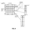
- FIG. 8illustrates an example of resource allocation and downlink acknowledgement transmission.
- the terms “a” or “an,” as used herein,are defined as one or more than one.
- the term “plurality,” as used herein,is defined as two or more than two.
- the term “another,” as used herein,is defined as at least a second or more.
- the terms “including” and/or “having,” as used herein,are defined as comprising (i.e., open language).
- the term “coupled” as used herein,are defined as connected, although not necessarily directly, and not necessarily mechanically.
- the term “user element”can be any portable component or group of portable components that are capable of receiving and/or transmitting communications signals.
- a “base station”can be any infrastructure component that is capable of exchanging wireless signals with a user element.
- a “transceiver”can be any component or group of components that are capable of receiving or transmitting wireless signals over a suitable medium.
- the term “data”can mean any type of information that can be transmitted over a wireless medium.
- a “scheduler”can include any component or group of components that are capable of allocating resources in accordance with the description herein using any suitable form of hardware, software or combination thereof.
- a “processor”can be defined as a component or a group of components that can process allocation information from a base station in accordance with the description herein using any suitable form of hardware, software or combination thereof.
- uplinkcan refer to transmissions from a user element to a base station
- downlinkcan refer to transmissions from a base station to a user element.
- multiple-input multiple-outputrefers to a system or technique in which multiple transmit antennas and multiple receiver antennas are deployed.
- a “multi-user multiple input multiple output communication system”means a wireless communication system in which a plurality of UEs are allowed to transmit over the same time-frequency resources.
- An “acknowledgement”can mean any indication as to whether a transmitted signal was correctly received.
- an “acknowledgement channel”can mean any medium that conveys acknowledgements.
- the methodcan include the step of transmitting to multiple UEs over a DL channel a UL SG that includes information relating to allocation of resource blocks in which the multiple UEs form a MU-MIMO group.
- Each UE of a MU-MIMO groupcan receive its own unique UL SG for the first packet transmission.
- the methodcan also include the steps of receiving from the UEs over a UL channel data in accordance with the resource block allocation and in response to receiving the data, transmitting acknowledgements on acknowledgement channels within a single acknowledgement bank to the UEs that give an indication as to whether the data was received correctly. This process reduces DL overhead and simultaneously preserves DL bandwidth in view of the single acknowledgement bank, as compared with systems requiring multiple acknowledgement banks.
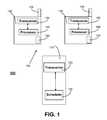
- a MU-MIMO communication system 100that operates in accordance with the LTE standard is shown in which a base station 110 is in wireless communications with a plurality of UEs 130 .
- the base station 110can communicate with the UEs 130 over a DL channel using the orthogonal frequency division multiple access (OFDMA) modulation scheme.
- the UEs 130can communicate with the base station 110 over an uplink channel using the single carrier-frequency division multiple access (SC-FDMA) technique.
- SC-FDMAsingle carrier-frequency division multiple access
- the base station 110can include a transceiver 120 and a scheduler 125 , which can be coupled to one another.
- the UEs 130can include a transceiver 135 and a processor 140 coupled to the transceiver 135 .
- the UEs 130may also include multiple antennas 145 , which can form part of a MIMO system.
- the transceiver 120can transmit to the UEs 130 over a DL channel an UL SG that includes information relating to the allocation of resource blocks.
- the scheduler 125can generate the UL SG. Subsequently, the UEs 130 may transmit data to the base station 110 in accordance with the resource block allocation set forth by the UL SG.
- the scheduler 125can generate acknowledgements on acknowledgement channels within an acknowledgement bank, which the transceiver 120 can transmit to the UEs 130 .
- the UEs 130can rely on this transmission to determine whether the base station 110 correctly received the previously-transmitted data.
- UEs 130 that are employed in a MU-MIMO systemmay share or be multiplexed on common allocation resources.
- the UEs 130may form a MU-MIMO group 150 .
- a MU-MIMO groupcan mean a set of two or more UEs that are multiplexed on common time-frequency resources.
- a MU-MIMO groupcan contain at least four UEs.
- the processes described hereinmay accommodate any ambiguities that may exist in a MU-MIMO group with respect to the channel assignments in the acknowledgement bank.
- a resource blockis a time-frequency allocation that is assigned to a UE and can be defined as the smallest element of resource allocation assigned by a scheduler, such as the scheduler 125 of the base station 110 .
- the resource block 230may extend over a slot 220 , which can be about 0.5 milli-seconds (msec) long and can be part of a subframe 215 , which may be approximately 1.0 msec in duration.
- the resource block 230may include six or seven symbols, depending on the type of cyclic prefix that is used, and the resource block 230 may include twelve sub-carriers 240 .
- the DL bandwidthcan be about five MHz, which results in twenty-five resource blocks 230 . It must be noted, however, that the claimed subject matter is not limited to this particular bandwidth, as it may apply to other suitable ranges.
- the resource block 230can be comprised of several resource elements 235 , which can represent a single sub-carrier 240 for a period of one symbol.
- reference symbolscan be periodically transmitted, such as every sixth sub-carrier 240 and can be staggered in both time and frequency. This pattern is for DL transmissions.
- These reference symbolsare represented in the resource blocks 230 as shaded resource elements designated with the letter “R” (with appropriate subscript numbers) and can be used to estimate channel response on the remaining sub-carriers 240 .
- each resource block 230can include reference symbols that are assigned to a particular antenna.
- the resource block 230 on the leftincludes reference symbols R 1 for a first transmitting antenna, while the resource block 230 on the right includes reference symbols R 2 for a second transmitting antenna.
- the resource elements 235 designated with an “X”denotes an unused resource element 235 for that particular resource block 230 in view of the multiple reference signals being transmitted from the other antennas.
- the sequential transmission of the reference symbols and the nulling of the other reference symbols not assigned to the transmitting antennacan be referred to as a demodulation reference symbol (DRS) format for the DL.
- DRSdemodulation reference symbol
- the DRS format for the resource block 230 on the left of FIG. 2can have a value of “0,” while the DRS format for the block 230 on the right can have a value of “1.”
- reference symbolscan be transmitted on the fourth symbol of each slot.
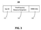
- the UL SG 300can be transmitted over a DL channel to the UEs 130 (see FIG. 1 ) and can include resource allocation that can be used by the UEs 130 for transmitting data to the base station 110 .
- a UL SGcan be defined as any element that can carry information relating to resource allocation.
- the UL SG 300can include a user identification (ID) block 310 , a time/frequency resource assignment block 320 and a space-division multiple access (SDMA) index 330 .
- IDuser identification
- SDMAspace-division multiple access
- the user ID block 310identifies the appropriate UEs 130 , and the time/frequency resource assignment block 320 enables the UEs 130 to determine which resources to use for transmitting data on the relevant UL channel.
- the SDMA index 330can point to a particular DRS format (see FIG. 5 ) with unique cyclic shift so DRS uplink transmissions by each UE 130 of the MU-MIMO group are orthogonal.
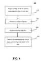
- FIG. 4a method 400 for resource allocation is shown.
- this method 400reference will be made to FIGS. 1-3 , although it must be understood that the method 400 can be practiced in any other suitable system or component using any other suitable modulation scheme or protocol.
- FIG. 5shows an example of the process described in the method 400 .
- the steps of the method 400are not limited to the particular order in which they are presented in the figures. Moreover, any of these methods can have a greater number of steps or a fewer number of steps than those shown in the figures.
- pointing valuescan be assigned to an index associated with one or more UEs, and at step 420 , a UL SG can be transmitted to multiple UEs over a DL channel (i.e., a distinct UL SG is transmitted to each UE). Data may then be received over an UL channel in accordance with the UL SG, as shown at step 430 .
- the base station 110can assign pointing values to the UEs 130 that make up a MU-MIMO group 150 , and these pointing values can be contained in the SDMA index 330 .
- four UEs 130may form a MU-MIMO group 150 , and the base station 110 can assign values from the set 0 , 1 , 2 and 3 to the UEs 130 , as shown in the SDMA index 330 of FIG. 5 .
- the base station 110can arbitrarily assign these values to the UEs 130 or can assign them based on a preferred DRS format for one or more of the UEs 130 .
- the base station 110can transmit over a DL channel to the UEs 130 of the MU-MIMO group 150 the UL SG 300 .
- the UL SG 300can include information relating to resource allocation, such as the allocation of resource blocks 230 .
- the UEs 130may transmit data to the base station 110 in accordance with the resource block 230 allocation of the UL SGs 300 , which the base station 110 can receive and process, assuming suitable channel conditions.
- the four UEs 130 of the MU-MIMO group 150can be allocated four resource blocks 230 , which are designated as RBs 5 - 8 in the UL subframe 510 of FIG. 5 .
- This resource sharingis associated with MU-MIMO communication systems.
- the SDMA index 330can point to the DRS format 540 for a particular UE 130 of the MU-MIMO group 150 .
- reference symbolscan be transmitted on the fourth symbol of each slot, which is represented by the shaded vertical section in the UL subframe 510 .
- the DRS format 540can indicate a cyclic shift to be employed by the UEs 130 .
- a UE 130 with an assigned value of “0” in the SDMA index 330can determine that its DRS format 540 will also be “0,” which is indicated in FIG. 5 . This assignment corresponds to a cyclic shift of “0” of a known pattern for transmission as the reference symbols.
- a UE 130 with an assigned value of “1” in the index 330can determine that its DRS format will be “1,” as well.
- acknowledgements on acknowledgement channels within a single acknowledgement bankcan be transmitted to the UEs, which can provide an indication as to whether the data was correctly received.
- the scheduler 125can generate acknowledgements, which can be transmitted over acknowledgement channels within the acknowledgment bank 550 to the UEs 130 of the MU-MIMO group 150 .
- An acknowledgement bankwhich may also be referred to as a physical HARQ indicator channel (PHICH) bank, can be defined as any element that can include indications as to whether a particular transmission was correctly received.
- the acknowledgement bank 550can include a set of channels that carry ACKs or NACKs.
- the acknowledgement bank 550may also include twenty-five acknowledgement channels, which refer to the transmissions from the UEs 130 . These acknowledgement channels may also be referred to as PHICHs.
- sharing resourcesis common in MU-MIMO systems. As such, there may be some ambiguity in the UEs 130 determining which location (i.e., channel) in the acknowledgement bank 530 applies to a particular UE 130 . That is, the UEs 130 that are sharing the resource blocks 230 labeled RB 5 through RB 8 may not be sure which of the acknowledgment channels 5 - 8 to monitor in the acknowledgement bank 550 .
- the multiplexed UEs 130 in the MU-MIMO group 150may refer to the SDMA index 330 and the allocation of resource blocks 230 to determine which channel in the acknowledgement bank 550 to monitor for the acknowledgements.
- the resource blocks 5 - 8have been allocated to this particular MU-MIMO group.
- the UEs 130can then add the value 5, which represents the first resource block in the allocation, and add it to its unique value from the SDMA index 330 to determine the appropriate channel in the acknowledgement bank 550 .
- the UE 130 assigned with the value 0 in the SDMA index 330can combine this value with the value 5 to determine that its assigned acknowledgement channel in the bank 550 is channel A/N 5 .
- the UE 130 with a value of 1 in the index 330can determine that its assigned channel is A/N 6 , or value 1 plus value 5.
- the first resource block in the allocationcan serve as the reference point for determining the channels, it must be noted that the invention is not so limited, as the second or subsequent resource blocks can serve this function.
- the number of resource blocks 230 in the resource block allocationcan be greater than or equal to the number of UEs 130 in the MU-MIMO group 150 .
- the number of resource blocks 230 allocated to the MU-MIMO group 150can be greater than or equal to four. This constraint can ensure that there is a one-to-one mapping of the SDMA index 330 with the appropriate acknowledgement channels in the acknowledgement bank 550 , which limits the necessary acknowledgement banks 550 to one.
- An adaptive HARQ re-transmissionreceives an UL SG to indicate a change compared to the UL SG received for the first packet transmission or previous re-transmission.
- the changemight be changes to the resource allocation or modulation and coding scheme or some other control attribute.
- a non-adaptive HARQ re-transmissiondoes not receive an UL SG and relies on the information receive from the UL SG corresponding to the first transmission of the packet or a previous re-transmission of the current packet.
- the constraint of limiting the number of allocated resource blocks 230 to a value that is equal to or greater than the number of multiplexed UEs 130 in a MU-MIMO group 150is useful for employing the SDMA index 330 as an implicit pointer to guide the UEs 130 in determining which channel of the acknowledgement bank 550 to monitor.
- the number of multiplexed UEs 130is actually greater than the number of allocated resource blocks 230 .
- an alternative techniquecan be used to guide them in correctly locating their acknowledgement channels.
- a method 600 for selective use of CCE-based implicit pointingis shown.
- this method 600reference may be made to the other drawings herein, although it must be understood that the method 600 can be practiced in any other suitable system or component using any other suitable modulation scheme or protocol.
- FIGS. 7 and 8show examples of the processes described in the method 600 .
- the steps of the method 600are not limited to the particular order in which they are presented in the figures. Moreover, any of these methods can have a greater number of steps or a fewer number of steps than those shown in the figures.
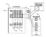
- a base stationtransmits UL SG scheduling grants are transmitted to one or more UEs on different physical channels of a Physical DL control channel (PDCCH) on a DL sub-frame.
- the UEscan be subset of the UEs in the MU-MIMO group.
- the PDCCH( 710 in FIG. 7 ) may consist of different time-frequency resource elements which may be grouped to form a control channel element (CCE).
- the physical channelcan consist of one or more CCEs.
- FIG. 7shows an example of 17 different possible physical channels obtained by combining different number of CCEs from a set of 8 CCEs. Physical channels are assigned to UEs on the PDCCH such that there is no overlap between the physical channels of any two UEs.
- the base stationIn response to the UL SG, the base station, in step 620 , receives data of the allocated resource blocks from at least one of the UEs. The base station then in response to the received data transmits acknowledgements on acknowledgement channels of a acknowledgement bank (PHICH bank, FIG. 7 , 730 ) to the UEs in step 620 .
- the acknowledgement channel used for transmitting the acknowledgement for a UEis based on the location of the physical channel used for transmitting the UL SG for the UE in step 610 .
- the index of the first CCE of the physical channel used for transmitting UL SG to the UEindicates the acknowledgment channel to use in the acknowledgment bank.
- CCE 1( 720 in FIG. 7 ) is associated with acknowledgment channel, PHICH 1
- CCE 2is associated with acknowledgment channel
- PHICH 2CCE 3 is associated with acknowledgment channel, PHICH 3
- the first CCE of the physical channels 1 , 9 , 13 , 15 , 17is CCE 1 and thus the PHICH 1 is the acknowledgment channel used for the UE that was transmitted UL SG on any one of these physical channel 1 , 9 , 13 , 15 , or 17 .
- acknowledgment channel PHICH 4 within the acknowledgment bankis used for transmitting the acknowledgement for the UE that was transmitted UL SG on physical channel 4 or 14 (CCE 4 is the first CCE of physical channel 4 , 14 and is associated with acknowledgment channel, PHICH 4 ).
- CCE 4is the first CCE of physical channel 4 , 14 and is associated with acknowledgment channel, PHICH 4 ).
- pointing to acknowledgment channels on a acknowledgment bankis based on location of the physical channel and in turn on the CCEs used.
- the size of the acknowledgment bankmay be approximately equal to the number of possible CCEs in the PDCCH. In another embodiment the size of the acknowledgment bank is approximately equal to the sum of the number of possible CCEs in the PDCCH in each PDCCH candidate uplink search region supported in a given subframe or supported by the network.
- a multi-user multiple-input multiple-output (MU-MIMO) communication systemmay use resource allocation of FIG. 4 or FIG. 6 or a combination thereof.
- resource allocation acknowledgementsare transmitted to a subset of UEs using RB based PHICH bank and to another subset of UEs using CCE based PHICH bank.
- the SDMA indexcan be used to indicate which CCE-based PHICH bank (given multiple CCE-based PHICH banks and no RB based PHICH banks) to use or the SDMA index can be used as an offset to drop down to a lower part of the CCE-based PHICH bank. This allows for only CCE-based pointing.
- a UE's SDMA indexis greater than the number of RBs in the MU-MIMO resource allocation then an offset is added to a CCE pointer to locate a portion of the CCE-based PHICH bank.
- the CCE-based PHICH bank sizemay be extended in this case.
- the offsetcould be equal to the total number of CCEs allocated for the PDCCHs used for UL SGs (e.g. 8 CCEs maybe allocated for UL SGs for a 5 MHz LTE carrier and hence there 8 PHICHs would be needed).
- Multiple CCE-based bankscan be viewed as one large CCE-based bank. For example, the size of the one large CCE-based bank can be larger than the total number of CCEs allocated for all UL SG PDCCHs in a given subframe.
- FIG. 8Another embodiment for resource allocation and downlink acknowledgement transmission is shown in FIG. 8 .
- a base stationtransmits uplink scheduling grants to MU-MIMO UEs in a MU-MIMO group indicating a MU-MIMO resource allocation for each UE's first packet transmission.
- UEs in the MU-MIMO groupuse the CCE pointer-based PHICH bank for locating its acknowledgement channel (PHICH) whenever they receive a scheduling grant otherwise they use the RB pointer-based PHICH bank.
- PHICHacknowledgement channel
- a SDMA indexwhich is used to determine the DRS format (cyclic shift) and when added, for example, to the first resource block index in the MU-MIMO resource allocation determines the PHICH index in the RB-pointer based PHICH bank which is used to locate the acknowledgement channel (PHICH) for retransmissions that did not have a corresponding UL SG.
- the base stationdoes not send uplink scheduling grants to MU-MIMO UEs and the MU-MIMO UEs use the PHICH index determined from the previous UL SG.
- UL SGsare sent to a UE not in the MU-MIMO group (e.g., non-MU-MIMO UE or MU-MIMO UE in another MU-MIMO group) if one or more of its allocated resource blocks is within N resource blocks of the first resource block of the MU-MIMO group resource block allocation.
- the value Ncan be equal to the number of UEs in the MU-MIMO group, and the UL SG is transmitted over a physical channel that makes up a physical downlink control channel (PDCCH).
- the physical channelis comprised of one or more control channel elements (CCE).
- Nis equal to 8.
- the acknowledgement channel used for transmitting acknowledgements to a UEwas sent an uplink scheduling grant based on the location physical channel used for transmitting the uplink scheduling grant in the PDCCH.
- the index of the first CCE of the physical channel used for transmitting UL SG to the UEindicates the acknowledgment channel to use in the CCE pointer-based PHICH (acknowledgment) bank.
Landscapes
- Engineering & Computer Science (AREA)
- Signal Processing (AREA)
- Computer Networks & Wireless Communication (AREA)
- Multimedia (AREA)
- Mobile Radio Communication Systems (AREA)
Abstract
Description
Claims (17)
Priority Applications (12)
| Application Number | Priority Date | Filing Date | Title |
|---|---|---|---|
| US12/178,754US8379601B2 (en) | 2007-08-16 | 2008-07-24 | Method and system for selective use of control channel element based implicit pointing |
| PCT/US2008/072750WO2009026018A2 (en) | 2007-08-16 | 2008-08-11 | Method and system for selective use of control channel element based implicit pointing |
| CA2694660ACA2694660C (en) | 2007-08-16 | 2008-08-11 | Method and system for selective use of control channel element based implicit pointing |
| CN200880103175.8ACN101779405B (en) | 2007-08-16 | 2008-08-11 | Methods used to manage confirmation |
| JP2010519283AJP4974016B2 (en) | 2007-08-16 | 2008-08-11 | Method and system for selective use of implicit indications based on control channel elements |
| MX2010001800AMX2010001800A (en) | 2007-08-16 | 2008-08-11 | Method and system for selective use of control channel element based implicit pointing. |
| EP08827715.7AEP2188939B8 (en) | 2007-08-16 | 2008-08-11 | Method for selective use of control channel element based implicit pointing |
| MYPI2010000486AMY159426A (en) | 2007-08-16 | 2008-08-11 | Method and system for selective use of control channel element based implicit pointing |
| BRPI0815475ABRPI0815475B1 (en) | 2007-08-16 | 2008-08-11 | method for managing confirmations through the selective use of control channel element based on implicit signaling |
| RU2010109755/08ARU2452108C2 (en) | 2007-08-16 | 2008-08-11 | Method and system for selective use of control channel element based implicit pointing |
| KR1020107003226AKR101109881B1 (en) | 2007-08-16 | 2008-08-11 | Method and system for selective use of control channel element based implicit pointing |
| ZA2010/00846AZA201000846B (en) | 2007-08-16 | 2010-02-04 | Method and system for selective use of control channel element based implicit pointing |
Applications Claiming Priority (2)
| Application Number | Priority Date | Filing Date | Title |
|---|---|---|---|
| US95633407P | 2007-08-16 | 2007-08-16 | |
| US12/178,754US8379601B2 (en) | 2007-08-16 | 2008-07-24 | Method and system for selective use of control channel element based implicit pointing |
Publications (2)
| Publication Number | Publication Date |
|---|---|
| US20090046793A1 US20090046793A1 (en) | 2009-02-19 |
| US8379601B2true US8379601B2 (en) | 2013-02-19 |
Family
ID=40362949
Family Applications (1)
| Application Number | Title | Priority Date | Filing Date |
|---|---|---|---|
| US12/178,754Active2029-10-29US8379601B2 (en) | 2007-08-16 | 2008-07-24 | Method and system for selective use of control channel element based implicit pointing |
Country Status (12)
| Country | Link |
|---|---|
| US (1) | US8379601B2 (en) |
| EP (1) | EP2188939B8 (en) |
| JP (1) | JP4974016B2 (en) |
| KR (1) | KR101109881B1 (en) |
| CN (1) | CN101779405B (en) |
| BR (1) | BRPI0815475B1 (en) |
| CA (1) | CA2694660C (en) |
| MX (1) | MX2010001800A (en) |
| MY (1) | MY159426A (en) |
| RU (1) | RU2452108C2 (en) |
| WO (1) | WO2009026018A2 (en) |
| ZA (1) | ZA201000846B (en) |
Cited By (6)
| Publication number | Priority date | Publication date | Assignee | Title |
|---|---|---|---|---|
| US20100103860A1 (en)* | 2008-10-27 | 2010-04-29 | Hak Seong Kim | Method of operating relay station in wireless communication system |
| US20100322257A1 (en)* | 2009-05-18 | 2010-12-23 | Electronics And Telecommunications Research Institute | Sensor node for using asynchronous mac |
| US20120263097A1 (en)* | 2010-01-07 | 2012-10-18 | Zte Corporation | Mapping and resource allocation method for relay link-physical downlink shared channel |
| US20130064196A1 (en)* | 2011-09-12 | 2013-03-14 | Research In Motion Limited | Searching Space and Operation for Enhanced PDCCH in LTE Systems |
| US9887752B2 (en) | 2011-02-11 | 2018-02-06 | Interdigital Patent Holdings, Inc. | Managing control signaling overhead for multi-carrier HSDPA |
| US20180367283A1 (en)* | 2017-06-16 | 2018-12-20 | Qualcomm Incorporated | Strategic mapping of uplink resources |
Families Citing this family (44)
| Publication number | Priority date | Publication date | Assignee | Title |
|---|---|---|---|---|
| USRE44564E1 (en)* | 2006-10-02 | 2013-10-29 | Lg Electronics Inc. | Method for transmitting control signal using efficient multiplexing |
| ES2902275T3 (en) | 2007-03-19 | 2022-03-25 | Lg Electronics Inc | A resource allocation method and a method for transmitting/receiving resource allocation information in a mobile communication system |
| KR101049138B1 (en) | 2007-03-19 | 2011-07-15 | 엘지전자 주식회사 | In a mobile communication system, an acknowledgment signal receiving method |
| KR100913090B1 (en) | 2007-06-13 | 2009-08-21 | 엘지전자 주식회사 | A method for transmitting spread-signal in a communication system |
| KR100908063B1 (en) | 2007-06-13 | 2009-07-15 | 엘지전자 주식회사 | Method of transmitting a spread signal in a mobile communication system |
| US8204010B2 (en) | 2007-06-18 | 2012-06-19 | Research In Motion Limited | Method and system for dynamic ACK/NACK repetition for robust downlink MAC PDU transmission in LTE |
| KR100900289B1 (en) | 2007-06-21 | 2009-05-29 | 엘지전자 주식회사 | A method for transmitting and receiving a control channel in the Orthogonal Frequency Division Multiplexing system |
| KR101457688B1 (en)* | 2007-10-04 | 2014-11-12 | 엘지전자 주식회사 | Method of Data Transmission Detecting Errors in Receiving Control Channel |
| JP5340175B2 (en) | 2008-01-04 | 2013-11-13 | パナソニック株式会社 | Radio communication base station apparatus, radio communication mobile station apparatus, and control channel allocation method |
| KR100943908B1 (en) | 2008-02-19 | 2010-02-24 | 엘지전자 주식회사 | Control information transmission and reception method through PDCHC |
| CN101252422B (en)* | 2008-03-20 | 2013-06-05 | 中兴通讯股份有限公司 | Method for allocating physical mixing retransmission indicating chanel |
| US8374109B2 (en)* | 2008-03-27 | 2013-02-12 | Qualcomm Incorporated | Methods of sending control information for users sharing the same resource |
| WO2010016669A2 (en) | 2008-08-04 | 2010-02-11 | Samsung Electronics Co., Ltd. | Signal transmission method and apparatus for user equipment in mobile communication system |
| EP3255947B1 (en) | 2008-08-08 | 2021-11-03 | Sun Patent Trust | Communications apparatus and method |
| US8467345B2 (en)* | 2008-08-20 | 2013-06-18 | Qualcomm Incorporated | Methods and apparatus for scheduling wireless transmissions |
| KR101255459B1 (en)* | 2009-02-02 | 2013-04-16 | 후지쯔 가부시끼가이샤 | Wireless communication system, base station device, terminal device and wireless communication method employed in wireless communication system |
| US9450727B2 (en) | 2009-02-03 | 2016-09-20 | Google Technology Holdings LLC | Physical layer acknowledgement signaling resource allocation in wireless communication systems |
| US8532015B2 (en)* | 2009-02-20 | 2013-09-10 | Nokia Siemens Networks Oy | Methods and apparatuses for transmitting downlink control signaling on wireless relay link |
| KR101478316B1 (en)* | 2009-04-28 | 2014-12-31 | 한국전자통신연구원 | Method for transmitting dedicated reference signal, and method for receiving dedicated reference signal |
| KR20110038994A (en)* | 2009-10-09 | 2011-04-15 | 삼성전자주식회사 | Method and apparatus for multi-user control channel transmission and reception in wireless communication system using multiple antennas |
| CN102014496B (en)* | 2009-10-16 | 2013-07-31 | 电信科学技术研究院 | Method, equipment and system for configuring uplink control channel resources |
| WO2011046413A2 (en)* | 2009-10-16 | 2011-04-21 | 엘지전자 주식회사 | Method and apparatus for transmitting multi-user mimo reference signal in wireless communication system for supporting relay |
| GB201002215D0 (en) | 2010-02-10 | 2010-03-31 | Nec Corp | Resource allocation signalling |
| US8964670B2 (en)* | 2010-02-25 | 2015-02-24 | Lg Electronics Inc. | Method for transmitting control information in a wireless communication system using multiple carriers |
| US8855067B2 (en)* | 2010-04-02 | 2014-10-07 | Marvell World Trade Ltd. | Multi-user communication group management and signaling |
| US9160431B2 (en) | 2010-04-27 | 2015-10-13 | Qualcomm Incorporated | Efficient group definition and overloading for multiuser MIMO transmissions |
| US9089002B2 (en) | 2010-05-16 | 2015-07-21 | Qualcomm Incorporated | Efficient group ID management for wireless local area networks (WLANs) |
| US8194687B2 (en)* | 2010-07-23 | 2012-06-05 | Intel Corporation | Access point configured for station group management and method for managing station-management groups |
| EP2413557A1 (en)* | 2010-07-28 | 2012-02-01 | Telefonaktiebolaget L M Ericsson (Publ) | Test signal in an OFDM receiver |
| US20130201954A1 (en)* | 2010-10-14 | 2013-08-08 | Keilalahdentie 4 | Device to Device and Connection Mode Switching |
| JP6125496B2 (en) | 2011-06-15 | 2017-05-10 | サムスン エレクトロニクス カンパニー リミテッド | Extending physical downlink control signaling in communication systems |
| GB2498815A (en)* | 2012-01-30 | 2013-07-31 | Renesas Mobile Corp | Enhanced PHICH with multibit ACK/NAK |
| US9602262B2 (en) | 2012-04-17 | 2017-03-21 | Lg Electronics Inc. | Method for setting search regions for downlink control channels in wireless communication systems and apparatus for same |
| CN106488568B (en)* | 2012-07-20 | 2020-01-31 | 华为技术有限公司 | A data transmission method, device and communication system |
| HUE037326T2 (en)* | 2012-10-26 | 2018-08-28 | Intel Corp | User plane overload report |
| CN104604319B (en) | 2013-03-27 | 2018-12-04 | Lg 电子株式会社 | Method and device for performing channel access in WLAN system |
| CN103636276B (en) | 2013-04-18 | 2017-11-17 | 华为技术有限公司 | A kind of control channel method for sending information and device based on common cell networking |
| CN109245808B (en) | 2013-06-25 | 2020-09-25 | 华为技术有限公司 | Upstream multi-user data transmission method and upstream multi-user input and output system |
| CA2937309A1 (en)* | 2014-01-24 | 2015-07-30 | The Trustees Of The University Of Pennsylvania | Linear motion device with extending tube for positioning |
| CN105681007B (en) | 2014-11-19 | 2020-11-06 | 北京三星通信技术研究有限公司 | Reference signal sending and receiving method and device, and scheduling method and device |
| JP6618125B2 (en) | 2015-05-29 | 2019-12-11 | 華為技術有限公司Huawei Technologies Co.,Ltd. | Resource mapping method and apparatus |
| SG11201805839YA (en) | 2016-01-07 | 2018-08-30 | Nokia Solutions & Networks Oy | Method and apparatus for allocating acknowledgement resources |
| GB2568315B (en)* | 2017-11-14 | 2020-06-17 | Cambium Networks Ltd | Fault Tolerant Transmission for a Wireless Link |
| US12068856B2 (en)* | 2018-08-10 | 2024-08-20 | Qualcomm Incorporated | Group feedback techniques in wireless systems |
Citations (23)
| Publication number | Priority date | Publication date | Assignee | Title |
|---|---|---|---|---|
| WO2004073200A1 (en) | 2003-02-11 | 2004-08-26 | Samsung Electronics Co. Ltd. | Method of reducing feedback channel state information within adaptive ofdma system and adaptive ofdma system using the same |
| US20050122898A1 (en) | 2003-11-05 | 2005-06-09 | Samsung Electronics Co., Ltd. | HARQ method for guaranteeing QoS in a wireless communication system |
| EP1599403A1 (en) | 2002-12-19 | 2005-11-30 | Christopher Max Modra | A laser cutting apparatus |
| US20060133273A1 (en) | 2004-12-22 | 2006-06-22 | Qualcomm Incorporated | Apparatus and method for efficient transmission of acknowledgments |
| US20070047502A1 (en) | 2005-08-24 | 2007-03-01 | Interdigital Technology Corporation | Method and apparatus for adjusting channel quality indicator feedback period to increase uplink capacity |
| US20070097981A1 (en) | 2005-11-02 | 2007-05-03 | Aris Papasakellariou | Methods for Determining the Location of Control Channels in the Uplink of Communication Systems |
| US20070171849A1 (en) | 2006-01-03 | 2007-07-26 | Interdigital Technology Corporation | Scheduling channel quality indicator and acknowledgement/negative acknowledgement feedback |
| WO2007148710A1 (en) | 2006-06-20 | 2007-12-27 | Nec Corporation | Sub-carrier allocation for control data in a communications system |
| US20080051125A1 (en) | 2006-08-22 | 2008-02-28 | Tarik Muharemovic | Adaptive Selection of Transmission Parameters for Reference Signals |
| US20080070582A1 (en)* | 2006-09-19 | 2008-03-20 | Sean Cai | Frame Structure For Multi-Hop Relay In Wireless Communication Systems |
| US20080084853A1 (en) | 2006-10-04 | 2008-04-10 | Motorola, Inc. | Radio resource assignment in control channel in wireless communication systems |
| US20080117878A1 (en) | 2006-11-17 | 2008-05-22 | Samsung Electronics Co., Ltd. | Apparatus and method for transmitting/receiving data in a communication system |
| WO2008085000A1 (en) | 2007-01-10 | 2008-07-17 | Samsung Electronics Co., Ltd. | Method and apparatus for allocating and signaling ack/nack resources in a wireless communication system |
| US20080205348A1 (en) | 2007-01-26 | 2008-08-28 | Qualcomm Incorporated | Mapping uplink acknowledgement transmission based on downlink virtual resource blocks |
| WO2008133454A1 (en) | 2007-04-26 | 2008-11-06 | Samsung Electronics Co., Ltd. | Method and apparatus for allocating ackch resources in a wireless communication system |
| WO2008137864A2 (en) | 2007-05-04 | 2008-11-13 | Qualcomm Incorporated | Method and apparatus for ul ack allocation |
| US20090103482A1 (en) | 2007-10-22 | 2009-04-23 | Sharp Laboratories Of America, Inc. | Systems and methods for using a format of an uplink control channel to transmit a channel quality indicator |
| US20090109906A1 (en) | 2007-10-30 | 2009-04-30 | Motorola Inc | Allocating downlink acknowledgement resources in wireless communication networks |
| US20090196274A1 (en) | 2008-02-01 | 2009-08-06 | Qualcomm, Incorporated | Frequency error estimation |
| US7774686B2 (en)* | 2008-03-16 | 2010-08-10 | Lg Electronics Inc. | Method for effectively transmitting control signal in wireless communication system |
| US7804800B2 (en)* | 2006-03-31 | 2010-09-28 | Intel Corporation | Efficient training schemes for MIMO based wireless networks |
| US20110194524A1 (en) | 2008-10-08 | 2011-08-11 | Leo Hedlund | Method and Apparatus for Selecting Control Channel Elements for Physical Downlink Control Channel |
| US8165035B2 (en)* | 2007-10-02 | 2012-04-24 | Nokia Siemens Networks Oy | ACK/NACK DTX detection |
Family Cites Families (3)
| Publication number | Priority date | Publication date | Assignee | Title |
|---|---|---|---|---|
| KR100267856B1 (en)* | 1997-04-16 | 2000-10-16 | 윤종용 | Over head channel management method an apparatus in mobile communication system |
| FI105136B (en)* | 1997-04-21 | 2000-06-15 | Nokia Mobile Phones Ltd | General package radio service |
| WO2007081564A2 (en)* | 2006-01-03 | 2007-07-19 | Interdigital Technology Corporation | Scheduling channel quality indicator and acknowledgement/negative acknowledgement feedback |
- 2008
- 2008-07-24USUS12/178,754patent/US8379601B2/enactiveActive
- 2008-08-11WOPCT/US2008/072750patent/WO2009026018A2/enactiveApplication Filing
- 2008-08-11MYMYPI2010000486Apatent/MY159426A/enunknown
- 2008-08-11KRKR1020107003226Apatent/KR101109881B1/enactiveActive
- 2008-08-11EPEP08827715.7Apatent/EP2188939B8/enactiveActive
- 2008-08-11CNCN200880103175.8Apatent/CN101779405B/enactiveActive
- 2008-08-11CACA2694660Apatent/CA2694660C/enactiveActive
- 2008-08-11BRBRPI0815475Apatent/BRPI0815475B1/enactiveIP Right Grant
- 2008-08-11RURU2010109755/08Apatent/RU2452108C2/enactive
- 2008-08-11MXMX2010001800Apatent/MX2010001800A/enactiveIP Right Grant
- 2008-08-11JPJP2010519283Apatent/JP4974016B2/enactiveActive
- 2010
- 2010-02-04ZAZA2010/00846Apatent/ZA201000846B/enunknown
Patent Citations (25)
| Publication number | Priority date | Publication date | Assignee | Title |
|---|---|---|---|---|
| EP1599403A1 (en) | 2002-12-19 | 2005-11-30 | Christopher Max Modra | A laser cutting apparatus |
| WO2004073200A1 (en) | 2003-02-11 | 2004-08-26 | Samsung Electronics Co. Ltd. | Method of reducing feedback channel state information within adaptive ofdma system and adaptive ofdma system using the same |
| US20050122898A1 (en) | 2003-11-05 | 2005-06-09 | Samsung Electronics Co., Ltd. | HARQ method for guaranteeing QoS in a wireless communication system |
| US20060133273A1 (en) | 2004-12-22 | 2006-06-22 | Qualcomm Incorporated | Apparatus and method for efficient transmission of acknowledgments |
| US7440399B2 (en)* | 2004-12-22 | 2008-10-21 | Qualcomm Incorporated | Apparatus and method for efficient transmission of acknowledgments |
| US20070047502A1 (en) | 2005-08-24 | 2007-03-01 | Interdigital Technology Corporation | Method and apparatus for adjusting channel quality indicator feedback period to increase uplink capacity |
| US20070097981A1 (en) | 2005-11-02 | 2007-05-03 | Aris Papasakellariou | Methods for Determining the Location of Control Channels in the Uplink of Communication Systems |
| US20070171849A1 (en) | 2006-01-03 | 2007-07-26 | Interdigital Technology Corporation | Scheduling channel quality indicator and acknowledgement/negative acknowledgement feedback |
| US7804800B2 (en)* | 2006-03-31 | 2010-09-28 | Intel Corporation | Efficient training schemes for MIMO based wireless networks |
| WO2007148710A1 (en) | 2006-06-20 | 2007-12-27 | Nec Corporation | Sub-carrier allocation for control data in a communications system |
| US20080051125A1 (en) | 2006-08-22 | 2008-02-28 | Tarik Muharemovic | Adaptive Selection of Transmission Parameters for Reference Signals |
| US20080070582A1 (en)* | 2006-09-19 | 2008-03-20 | Sean Cai | Frame Structure For Multi-Hop Relay In Wireless Communication Systems |
| US7873002B2 (en)* | 2006-09-19 | 2011-01-18 | Zte (Usa) Inc. | Frame structure for multi-hop relay in wireless communication systems |
| US20080084853A1 (en) | 2006-10-04 | 2008-04-10 | Motorola, Inc. | Radio resource assignment in control channel in wireless communication systems |
| US20080117878A1 (en) | 2006-11-17 | 2008-05-22 | Samsung Electronics Co., Ltd. | Apparatus and method for transmitting/receiving data in a communication system |
| WO2008085000A1 (en) | 2007-01-10 | 2008-07-17 | Samsung Electronics Co., Ltd. | Method and apparatus for allocating and signaling ack/nack resources in a wireless communication system |
| US20080205348A1 (en) | 2007-01-26 | 2008-08-28 | Qualcomm Incorporated | Mapping uplink acknowledgement transmission based on downlink virtual resource blocks |
| WO2008133454A1 (en) | 2007-04-26 | 2008-11-06 | Samsung Electronics Co., Ltd. | Method and apparatus for allocating ackch resources in a wireless communication system |
| WO2008137864A2 (en) | 2007-05-04 | 2008-11-13 | Qualcomm Incorporated | Method and apparatus for ul ack allocation |
| US8165035B2 (en)* | 2007-10-02 | 2012-04-24 | Nokia Siemens Networks Oy | ACK/NACK DTX detection |
| US20090103482A1 (en) | 2007-10-22 | 2009-04-23 | Sharp Laboratories Of America, Inc. | Systems and methods for using a format of an uplink control channel to transmit a channel quality indicator |
| US20090109906A1 (en) | 2007-10-30 | 2009-04-30 | Motorola Inc | Allocating downlink acknowledgement resources in wireless communication networks |
| US20090196274A1 (en) | 2008-02-01 | 2009-08-06 | Qualcomm, Incorporated | Frequency error estimation |
| US7774686B2 (en)* | 2008-03-16 | 2010-08-10 | Lg Electronics Inc. | Method for effectively transmitting control signal in wireless communication system |
| US20110194524A1 (en) | 2008-10-08 | 2011-08-11 | Leo Hedlund | Method and Apparatus for Selecting Control Channel Elements for Physical Downlink Control Channel |
Non-Patent Citations (34)
| Title |
|---|
| 3rd Generation Partnership Project, "Technical Specification Group Radio Access Network; Evolved Universal Terrestrial Radio Access (E-UTRA); Physical Channels and Modulation (Release 8)," 3GPP TS 36.211 V8.5.0, Dec. 2008, pp. 1-82; Sophia Antipolis, France. |
| 3rd Generation Partnership Project, "Technical Specification Group Radio Access Network; Evolved Universal Terrestrial Radio Access (E-UTRA); Physical Layer Procedures (Release 8)," 3GPP TS 36.213 V8.5.0, Dec. 2008, pp. 1-74, Sophia Antipolis, France. |
| Alcatel-Lucent, "Signaling Resource Allocations in DL Control Channel" (3GPP TSG RAN WG1 #49bis, R1-072923), Jun. 25-29, 2007, 10 pages, Orlando USA. |
| Chu Rui Chang et al., "PN Offset Planning Strategies for Non-Uniform CDMA Networks," IEEE 47th Vehicular Tech. Conf., pp. 1543-1547, May 1997. |
| Ericsson, "Begin-End representation of scheduling allocations" (3GPP TSG RAN WG1 #49bis, R1-073052), Jun. 25-29, 2007, 2 pages, Orlando USA. |
| Hyung G. Myung, "Technical Overview of 3GPP LTE", May 18, 2008, pp. 1-53. |
| Jim Zyren and Dr. Wes McCoy, "Overview of the 3GPP Long Term Evolution Physical Layer", Jul. 2007, pp. 1-27, Freescale Semiconductor. |
| Korean Intellectual Property Office, "Non-Final Rejection" for Application No. 10-2010-7011837, Aug. 16, 2011, 2 pages. |
| Korean Intellectual Property Office, "Non-Final Rejection" for Korean Application No. 10-2010-7003226, Apr. 11, 2011, 7 pages. |
| LG Electronics, "DL LVRB Assignment" (3GPP TSG RAN WG1 #49bis, R1-072877), Jun. 25-29, 2007, 4 pages, Orlando USA. |
| Mitsubishi Electric, "Scheduling Policy and Signaling Way on DL Resource Allocation" (3GPP TSG RAN WG1 #49bis, R1-072723), Jun. 25-29, 2007, 6 pages, Orlando USA. |
| Motorola et al., "Way Forward for DL Resource Allocation Mapping" (3GPP TSG RAN WG1 #49bis, R1-073227), Jun. 25-29, 2007, 4 pages, Orlando USA. |
| Motorola, "Downlink Resource Allocation Mapping for E-UTRA" (3GPP TSG RAN1 #50, R1-073372), Aug. 20-29, 2007, 5 pages, Athens Greece. |
| Motorola, "E-UTRA DL L1/L2 Control Channel Format for SIMO & MIMO" (3GPP TSG RAN WG1 #49bis R1-072697), Jun. 25-29, 2007, 7 pages, Orlando USA. |
| Motorola, "MU-MIMO PHICH Assignment for Adaptive and Non-Adaptive HARQ" (3GPP TSG RAN1 #50, R1-073409), Aug. 20-24, 2007, 4 pages, Athens Greece. |
| Motorola, "PHICH Resource Signaling for TDD & FDD", 3GPP TSG RAN1 #52bis, R1-081286, Apr. 1-5, 2008, pp. 1-4, Shenzhen, China. |
| NEC Group, "DL Unicast Resource Allocation Signalling Using L1L2 Control Channels" (3GPP TSG RAN WG1 #49bis, R1-072832), Jun. 25-29, 2007, 6 pages, Orlando USA. |
| NEC, Nokia, and Nokia Siemens Network, "Way Forward on Control Channels Multiplexing", TSG-RAN-WG1 #50bis, R1-074505, Oct. 8-12, 2007, pp. 1-3, Shanghai, China. |
| Nokia and Nokia Siemens Networks, "Additional Information on the Combinatorial PRB Allocation Signalling Method" (3GPP TSG RAN WG1 #49bis, R1-073217), Jun. 25-29, 2007, 4 pages, Orlando USA. |
| Nokia and Nokia Siemens Networks, "Signalling and Decoding of PRB Allocations LTE Downlink" (3GPP TSG RAN WG1 #49bis, R1-072997), Jun. 25-29, 2007, 5 pages, Orlando USA. |
| NTT Docomo et al., "ACK/NACK Signal Structure in E-UTRA Downlink" (3GPP TSG RAN WG1 Meeting #48, R1-070867, Original R1-063326), Feb. 12-16, 2007, 4 pages, St. Louis USA. |
| Patent Cooperation Treat, "International Search Report and Written Opinion of the International Searching Authority" for International Application. No. PCT/US2010/022485, May 18, 2010, 15 pages. |
| Patent Cooperation Treaty, "PCT Search Report and Written Opinion of the International Searching Authority" International Application No. PCT/US2008/079261, Mar. 19, 2009, 16 pages. |
| QUALCOMM Europe, "Impact of Constrained Resource Signaling in PDCCH" (3GPP TSG RAN WG1 #49bis, R1-072750), Jun. 25-29, 2007, 9 pages, Orlando USA. |
| Samsung, "Resource Indication Scheme for Downlink Packet Scheduling" (3GPP TSG RAN WG1 #49bis, R1-073119), Jun. 25-29, 2007, 4 pages, Orlando USA. |
| Third Generation Partnership Project and LG Electronics, "DL ACK/NACK Mapping Relations", 3GPP TSG RAN WG1 #49bis R1-072882, Jun. 25-29, 2007, 5 pages. |
| Third Generation Partnership Project and Motorola, "ACK/NACK Indication for SIMO and MU-MIMO", 3GPP TSG Ran1 #48bis R1-071431, Mar. 26-30, 2007. 3 pages. |
| Third Generation Partnership Project and Motorola, "Downlink Acknowledgment Channel", 3GPP TSG RAN1 #49 R1-072166, May 7-11, 2007, 3 pages. |
| Third Generation Partnership Project and Motorola, "E-UTRA DL L1/L2 Invariant Control Channel Mapping", 3GPP TSG RAN WG1 #48bis R1-071812, Mar. 26-30, 2007, 3 pages. |
| Third Generation Partnership Project and Motorola, "PHICH Assgnment for MU-MIMO in E-UTRA", 3GPP TSG RAN1 #50bis R1-074002, Oct. 8-12, 2007, 1 page. |
| Third Generation Partnership Project et al . "ACK/NACK Signal Structure in E-UTRA Downlink", 3GPP TSG RAN WG1 #48bis R1-071656, Mar. 26-30, 2007, 5 pages. |
| United States Patent and Trademark Office, "Non-Final Rejection" for U.S. Appl. No. 11/929,452, Aug. 18, 2010, 10 pages. |
| United States Patent and Trademark Office, "Non-Final Rejection" for U.S. Appl. No. 11/929,452, Jan. 19, 2012, 11 pages. |
| United States Patent and Trademark Office, "Non-Final Rejection" for U.S. Appl. No. 12/364,992, Apr. 19, 2012, 10 pages. |
Cited By (13)
| Publication number | Priority date | Publication date | Assignee | Title |
|---|---|---|---|---|
| US20100103860A1 (en)* | 2008-10-27 | 2010-04-29 | Hak Seong Kim | Method of operating relay station in wireless communication system |
| US8675542B2 (en)* | 2008-10-27 | 2014-03-18 | Lg Electronics Inc. | Method of operating relay station in wireless communication system |
| US8879466B2 (en)* | 2009-05-18 | 2014-11-04 | Electronics And Telecommunications Research Institute | Sensor node for using asynchronous MAC |
| US20100322257A1 (en)* | 2009-05-18 | 2010-12-23 | Electronics And Telecommunications Research Institute | Sensor node for using asynchronous mac |
| US20120263097A1 (en)* | 2010-01-07 | 2012-10-18 | Zte Corporation | Mapping and resource allocation method for relay link-physical downlink shared channel |
| US9241324B2 (en)* | 2010-01-07 | 2016-01-19 | Zte Corporation | Mapping and resource allocation method for relay link-physical downlink shared channel |
| US9887752B2 (en) | 2011-02-11 | 2018-02-06 | Interdigital Patent Holdings, Inc. | Managing control signaling overhead for multi-carrier HSDPA |
| US9084238B2 (en)* | 2011-09-12 | 2015-07-14 | Blackberry Limited | Searching space and operation for enhanced PDCCH in LTE systems |
| US8842628B2 (en) | 2011-09-12 | 2014-09-23 | Blackberry Limited | Enhanced PDCCH with transmit diversity in LTE systems |
| US20130064196A1 (en)* | 2011-09-12 | 2013-03-14 | Research In Motion Limited | Searching Space and Operation for Enhanced PDCCH in LTE Systems |
| US20180367283A1 (en)* | 2017-06-16 | 2018-12-20 | Qualcomm Incorporated | Strategic mapping of uplink resources |
| US10680782B2 (en)* | 2017-06-16 | 2020-06-09 | Qualcomm Incorporated | Strategic mapping of uplink resources |
| US11641262B2 (en) | 2017-06-16 | 2023-05-02 | Qualcomm Incorporated | Strategic mapping of uplink resources |
Also Published As
| Publication number | Publication date |
|---|---|
| RU2010109755A (en) | 2011-09-27 |
| ZA201000846B (en) | 2011-07-27 |
| KR101109881B1 (en) | 2012-02-17 |
| CN101779405B (en) | 2016-03-30 |
| RU2452108C2 (en) | 2012-05-27 |
| WO2009026018A3 (en) | 2009-06-18 |
| CA2694660A1 (en) | 2009-02-26 |
| BRPI0815475B1 (en) | 2020-04-14 |
| CA2694660C (en) | 2014-07-22 |
| EP2188939B8 (en) | 2016-07-06 |
| EP2188939A2 (en) | 2010-05-26 |
| MY159426A (en) | 2017-01-13 |
| CN101779405A (en) | 2010-07-14 |
| WO2009026018A2 (en) | 2009-02-26 |
| MX2010001800A (en) | 2010-03-10 |
| JP2010535000A (en) | 2010-11-11 |
| EP2188939B1 (en) | 2016-03-30 |
| US20090046793A1 (en) | 2009-02-19 |
| KR20100033532A (en) | 2010-03-30 |
| JP4974016B2 (en) | 2012-07-11 |
| BRPI0815475A2 (en) | 2015-02-10 |
Similar Documents
| Publication | Publication Date | Title |
|---|---|---|
| US8379601B2 (en) | Method and system for selective use of control channel element based implicit pointing | |
| US12375221B2 (en) | Method for mapping physical hybrid automatic repeat request indicator channel | |
| US10219255B2 (en) | Time domain multiplexing UL transmission on multiple serving cells for a mobile station with single transmitter | |
| US8279811B2 (en) | Allocating downlink acknowledgement resources in wireless communication networks | |
| CN105099634B (en) | Distribution method and device, base station, the terminal of dynamic resource | |
| CN101689980B (en) | Method and device for allocating acknowledgment/negative acknowledgment physical channel resources in wireless communication system | |
| EP3806365B1 (en) | Method for acquiring resource region information for phich | |
| US9674866B2 (en) | Subframe scheduling method and system, network device and terminal | |
| JP5596170B2 (en) | Communication device and method for determining HARQ timing in a communication device | |
| CN102447538B (en) | Downlink control information transmission method and system | |
| EP3484083A1 (en) | Communication system | |
| CN102647261B (en) | Scheduling signaling sending and response feedback method, system and equipment | |
| KR20100116210A (en) | Methods and apparatus to allocate acknowledgement channels | |
| RU2009135402A (en) | METHOD FOR TRANSMITTING CONTROL SIGNALS ON THE UPRESSING LINK IN A WIRELESS COMMUNICATION SYSTEM | |
| CN101882984A (en) | A data retransmission method and system |
Legal Events
| Date | Code | Title | Description |
|---|---|---|---|
| AS | Assignment | Owner name:MOTOROLA, INC., ILLINOIS Free format text:ASSIGNMENT OF ASSIGNORS INTEREST;ASSIGNORS:LOVE, ROBERT T.;NANGIA, VIJAY;REEL/FRAME:021284/0663;SIGNING DATES FROM 20070817 TO 20070820 Owner name:MOTOROLA, INC., ILLINOIS Free format text:ASSIGNMENT OF ASSIGNORS INTEREST;ASSIGNORS:LOVE, ROBERT T.;NANGIA, VIJAY;SIGNING DATES FROM 20070817 TO 20070820;REEL/FRAME:021284/0663 | |
| AS | Assignment | Owner name:MOTOROLA MOBILITY, INC, ILLINOIS Free format text:ASSIGNMENT OF ASSIGNORS INTEREST;ASSIGNOR:MOTOROLA, INC;REEL/FRAME:025673/0558 Effective date:20100731 | |
| AS | Assignment | Owner name:MOTOROLA MOBILITY LLC, ILLINOIS Free format text:ASSIGNMENT OF ASSIGNORS INTEREST;ASSIGNOR:MOTOROLA MOBILITY, INC.;REEL/FRAME:028829/0856 Effective date:20120622 | |
| STCF | Information on status: patent grant | Free format text:PATENTED CASE | |
| AS | Assignment | Owner name:GOOGLE TECHNOLOGY HOLDINGS LLC, CALIFORNIA Free format text:ASSIGNMENT OF ASSIGNORS INTEREST;ASSIGNOR:MOTOROLA MOBILITY LLC;REEL/FRAME:034371/0612 Effective date:20141028 | |
| FPAY | Fee payment | Year of fee payment:4 | |
| MAFP | Maintenance fee payment | Free format text:PAYMENT OF MAINTENANCE FEE, 8TH YEAR, LARGE ENTITY (ORIGINAL EVENT CODE: M1552); ENTITY STATUS OF PATENT OWNER: LARGE ENTITY Year of fee payment:8 | |
| MAFP | Maintenance fee payment | Free format text:PAYMENT OF MAINTENANCE FEE, 12TH YEAR, LARGE ENTITY (ORIGINAL EVENT CODE: M1553); ENTITY STATUS OF PATENT OWNER: LARGE ENTITY Year of fee payment:12 |