US8378981B2 - Capacitive sensing with high-frequency noise reduction - Google Patents
Capacitive sensing with high-frequency noise reductionDownload PDFInfo
- Publication number
- US8378981B2 US8378981B2US12/466,230US46623009AUS8378981B2US 8378981 B2US8378981 B2US 8378981B2US 46623009 AUS46623009 AUS 46623009AUS 8378981 B2US8378981 B2US 8378981B2
- Authority
- US
- United States
- Prior art keywords
- signal sample
- sample value
- change
- processed signal
- rate
- Prior art date
- Legal status (The legal status is an assumption and is not a legal conclusion. Google has not performed a legal analysis and makes no representation as to the accuracy of the status listed.)
- Active, expires
Links
Images


Classifications
- G—PHYSICS
- G06—COMPUTING OR CALCULATING; COUNTING
- G06F—ELECTRIC DIGITAL DATA PROCESSING
- G06F3/00—Input arrangements for transferring data to be processed into a form capable of being handled by the computer; Output arrangements for transferring data from processing unit to output unit, e.g. interface arrangements
- G06F3/01—Input arrangements or combined input and output arrangements for interaction between user and computer
- G06F3/03—Arrangements for converting the position or the displacement of a member into a coded form
- G06F3/041—Digitisers, e.g. for touch screens or touch pads, characterised by the transducing means
- G06F3/044—Digitisers, e.g. for touch screens or touch pads, characterised by the transducing means by capacitive means
- G—PHYSICS
- G06—COMPUTING OR CALCULATING; COUNTING
- G06F—ELECTRIC DIGITAL DATA PROCESSING
- G06F3/00—Input arrangements for transferring data to be processed into a form capable of being handled by the computer; Output arrangements for transferring data from processing unit to output unit, e.g. interface arrangements
- G06F3/01—Input arrangements or combined input and output arrangements for interaction between user and computer
- G06F3/03—Arrangements for converting the position or the displacement of a member into a coded form
- G06F3/041—Digitisers, e.g. for touch screens or touch pads, characterised by the transducing means
- G06F3/0416—Control or interface arrangements specially adapted for digitisers
- G06F3/0418—Control or interface arrangements specially adapted for digitisers for error correction or compensation, e.g. based on parallax, calibration or alignment
- G06F3/04182—Filtering of noise external to the device and not generated by digitiser components
- H—ELECTRICITY
- H03—ELECTRONIC CIRCUITRY
- H03K—PULSE TECHNIQUE
- H03K17/00—Electronic switching or gating, i.e. not by contact-making and –breaking
- H03K17/94—Electronic switching or gating, i.e. not by contact-making and –breaking characterised by the way in which the control signals are generated
- H03K17/96—Touch switches
- H03K17/962—Capacitive touch switches
- H03K17/9622—Capacitive touch switches using a plurality of detectors, e.g. keyboard
- G—PHYSICS
- G06—COMPUTING OR CALCULATING; COUNTING
- G06F—ELECTRIC DIGITAL DATA PROCESSING
- G06F3/00—Input arrangements for transferring data to be processed into a form capable of being handled by the computer; Output arrangements for transferring data from processing unit to output unit, e.g. interface arrangements
- G06F3/01—Input arrangements or combined input and output arrangements for interaction between user and computer
- G06F3/03—Arrangements for converting the position or the displacement of a member into a coded form
- G06F3/041—Digitisers, e.g. for touch screens or touch pads, characterised by the transducing means
- G06F3/044—Digitisers, e.g. for touch screens or touch pads, characterised by the transducing means by capacitive means
- G06F3/0446—Digitisers, e.g. for touch screens or touch pads, characterised by the transducing means by capacitive means using a grid-like structure of electrodes in at least two directions, e.g. using row and column electrodes
- H—ELECTRICITY
- H03—ELECTRONIC CIRCUITRY
- H03K—PULSE TECHNIQUE
- H03K2217/00—Indexing scheme related to electronic switching or gating, i.e. not by contact-making or -breaking covered by H03K17/00
- H03K2217/94—Indexing scheme related to electronic switching or gating, i.e. not by contact-making or -breaking covered by H03K17/00 characterised by the way in which the control signal is generated
- H03K2217/96—Touch switches
- H03K2217/9607—Capacitive touch switches
- H03K2217/960705—Safety of capacitive touch and proximity switches, e.g. increasing reliability, fail-safe
- H—ELECTRICITY
- H03—ELECTRONIC CIRCUITRY
- H03K—PULSE TECHNIQUE
- H03K2217/00—Indexing scheme related to electronic switching or gating, i.e. not by contact-making or -breaking covered by H03K17/00
- H03K2217/94—Indexing scheme related to electronic switching or gating, i.e. not by contact-making or -breaking covered by H03K17/00 characterised by the way in which the control signal is generated
- H03K2217/96—Touch switches
- H03K2217/9607—Capacitive touch switches
- H03K2217/96071—Capacitive touch switches characterised by the detection principle
- H03K2217/960725—Charge-transfer
Definitions
- the present inventionrelates to methods and apparatus for sensing the presence of a body from a change in an amount of charge present on a capacitively charged key.
- the present inventionalso relates to touch sensitive control panels which include a plurality of keys, which can be arranged in a matrix and can be used to form, for example, a two dimensional touch sensitive user input device.
- a touch sensorincludes a key comprising a drive plate and a sense plate, in which a charge signal may be measured after the key is driven during a measurement cycle.
- Touch sensitive control devicesare now prevalent on many electronic devices such as mobile phones, MP3 players, personal digital assistants as well as white goods such as cookers and freezers. This is because they are space saving in terms of an amount of “surface real estate” available to position user controls, robust in that there is a reduction in the amount of mechanical components required in their implementation and they can also be made to resist potentially harmful substances in an environment in which they are disposed.
- the touch sensitive switchcan be disposed behind a protective layer preventing damage from being caused by the aqueous substances.
- a touch sensitive controlcan be disposed in front of a display screen such as for example an LCD display screen with the effect that a user can select a particular function by touching the screen at a position at which a particular menu option has been displayed.
- touch sensitive controlswhich use a capacitive sensor to sense the presence of a body such as a user's finger.
- a touch sensitive capacitive sensorfor example is disclosed in WO-97/23738.
- WO-97/23738a single coupling plate is provided and disposed to form a touch sensitive switch.
- the touch sensitive plateis referred to as a key.
- the keyis charged using a drive circuit for a drive part of a measurement cycle and then this charge is measured by transferring the induced charge from the key by a charge detection circuit during a measurement part of the cycle.
- the charging and transferring parts of the cyclecan vary widely and can be selected in accordance with the application concerned.
- a burst of measurement cyclesare used to generate a plurality of signal sample values.
- the sensorcan detect the presence of an object near the key as a result of a change in an amount of the charge induced onto the key, even in the presence of interfering substances.
- WO-00/44018Another form of touch sensitive control is disclosed in WO-00/44018.
- a pair of electrodesare provided which act as a key so that the presence of a body such as a users finger is detected as a result of a change in an amount of charge which is transferred between the two electrodes.
- one of the electrodes(labelled X) is driven with a drive circuit and the other of the pair of electrodes (labelled Y) is connected to a charge measurement circuit which detects an amount of charge present on the Y plate when driven by the X plate.
- several pairs of electrodescan be arranged to form a matrix of sensing areas which can provide an efficient implementation of a touch sensitive two-dimensional position sensor.
- Such two dimensional capacitive transducing sensorsare typically used with devices which include touch sensitive screens or touch sensitive keyboards/keypads which are used in the example of consumer electronic devices and domestic appliances. As indicated above, such two dimensional capacitive touch sensors can be used in conjunction with liquid crystal displays or cathode ray tubes to form such touch sensitive screens.
- touch sensitive capacitive sensorssuch as those described above and disclosed in the above-mentioned disclosures have been successfully deployed in many applications, some applications can present a challenging environment for detecting a change in charge as a result of the presence of a body. For example, noise which may be present for a particular application can cause a disruption in accurately measuring an amount of charge transferred from a capacitively charged key for the various examples set out above.
- a method and apparatus for sensing the presence of a body from a change in an amount of charge present on a capacitively charged keyincludes performing a measurement burst which generates a plurality of signal sample values from a plurality of measurement cycles.
- Each of the measurement cyclesincludes inducing charge onto the key during a drive part of the measurement cycle, and during a signal measurement part of the measurement cycle measuring the charge induced on the key during the drive part of the measurement cycle, and generating a signal sample value to represent the charge measured from the key during the signal measurement part of the measurement cycle.
- the methodincludes comparing the value of the plurality of the signal sample values of the measurement burst with a determined range of accepted values between a determined maximum and a determined minimum value, and processing any of the plurality of signal sample values, which are outside the determined accepted range to the effect that the presence of a body can be determined from a change in the value of one or more of the plurality of signal samples which are within the determined accepted range.
- a determined range of accepted valuesbetween a determined maximum and a determined minimum value
- Embodiments of the present inventioncan provide a method and apparatus for improving an accuracy with which a signal measurement is taken from a capacitively charged key, and in particular can remove or at least reduce the effects of noise, which may otherwise cause an erroneous detection of the presence of a body, when one is not present.
- noisefor example impulsive or square wave noise having high frequency components, can cause a significant change in the value of signal samples, which are generated from a touch sensor which includes a capacitively charged key.
- the touch sensordetermines the presence of a body from a change in the value of the signal samples which are generated from bursts of measurement cycles.
- Each of the measurement cyclesproduces a signal sample, the value of the signal sample changing if the amount of charge transferred from the key during the measurement cycle changes as a result of the presence of a body, which acts as a shunt to remove charge from the key to earth.
- noisesuch as rectangular noise, can cause the value of the signal samples in a measurement burst to change, particularly when the signal sample coincides with a rising or failing edge of the rectangular noise, such as that typically generated by switching in an LCD screen.
- Embodiments of the present inventionprovide a technique for processing the signal sample values, which are produced from a touch sensor, to the effect of reducing the effects of noise which can cause a change in the signal sample value, which can be misinterpreted as the presence of a body proximate the touch sensor of the capacitively charged key.
- the processingcan include, for example, discarding the signal sample values which are outside the range.
- the accepted rangemay be defined by a determined maximum or determined minimum value of signal samples, which are generated for example, either periodically or during a test phase of the touch sensor, such as for example, during a power on or a start up phase.
- FIG. 1Ais a schematic block diagram providing an example of a touch sensitive sensor
- FIG. 1Bis an example illustration of a user's finger disposed proximate the sensor
- FIG. 2is a schematic block diagram illustrating an electrical equivalent of the touch sensor shown in FIG. 1B ;
- FIG. 3is a schematic block diagram of a circuit which in combination with the touch sensor shown in FIG. 1B serves to form a touch sensor;
- FIG. 4is an example timing diagram illustrating the operation of the sensing circuit shown in FIG. 3 ;
- FIG. 5is a schematic block diagram illustrating a touch sensitive matrix providing a two-dimensional capacitive transducing sensor arrangement
- FIG. 6is a schematic illustration showing an application of the two-dimensional capacitive transducing sensor shown in FIG. 5 ;
- FIG. 7is a graphical illustration showing a plot of signal strength with respect to time representing a voltage or charge present on a sensing key which has been affected by sinusoidal noise, such as mains noise;
- FIG. 8is a graphical illustration of a plot of signal strength with respect to time representing the voltage or charge on a sensing key in the presence of rectangular noise
- FIG. 9is a graphical representation of signal strength with respect to time for a combination of the sinusoidal shown in FIG. 7 and the rectangular noise shown in FIG. 8 ;
- FIG. 10 ais a graphical representation of a plot signal strength with respect to time in which rectangular noise is superimposed on the measured signal
- FIG. 10 bis a plot of signal strength against time representing sampled measurements of the charge present on a key according to the diagram of FIG. 10 a
- FIG. 10 cis an illustration of the relative value of the each of the samples shown in FIG. 10 b with respect to time;
- FIG. 11is a graphical representation of a plot of signal value with respect to time for an example in which a body has been move to be proximate a sensing key for a period of time;
- FIG. 12is a schematic block diagram illustrating process elements or steps in an operation of processing the samples of the charge including the noise in order to suppress the rectangular noise shown in FIG. 10 a;
- FIG. 13 ais a graphical representation of an effect of processing the samples of the charge with respect to time shown in FIG. 10 b by band pass filtering;
- FIG. 13 bis a graphical representation of a plot of signal amplitude with respect to time resulting from the processing performed by a slew rate limiter shown in FIG. 12 ;
- FIG. 13 cis a graphical representation of the values of the measured charge produced by averaging the samples of the charge by the process shown in FIG. 12 ;
- FIGS. 14 a and 14 bprovide an example flow diagram illustrating the operation of the touch sensor according to the present technique.
- FIG. 15is a flow diagram illustrating one example of a process for adapting the rate of change or slew rate of the signal sample values as performed by the processing technique illustrated in FIGS. 14 a and 14 b.
- FIGS. 1A and 1BAn example of such a touch sensor is shown in FIGS. 1A and 1B .
- the example shown in FIGS. 1A and 1Bcorrespond to an example in which a pair of electrodes form a touch sensor.
- a pair of electrodes 100 , 104which form a drive or X plate and a receiving or Y plate in the following description are disposed beneath the surface of a touch sensitive control panel 15 .
- FIGS. 1Aa pair of electrodes 100 , 104 which form a drive or X plate and a receiving or Y plate in the following description are disposed beneath the surface of a touch sensitive control panel 15 .
- the touch sensor 10is arranged to detect the presence of a body such as a user's finger 20 as a result of a change in an amount of charge transferred from the Y plate 104 .
- a bodysuch as a user's finger 20
- FIG. 1Awhen the X plate 100 is charged or driven by a circuit, an electric field is formed which is illustrated by the lines 18 and 19 both above and below the touch panel surface 15 as a result of which charge is transferred to the Y plate 104 .
- the X plate and the Y plate 100 , 104form a capacitively charged key 10 .
- FIG. 1Awhen the X plate 100 is charged or
- FIG. 2An equivalent circuit diagram of the touch sensor shown in FIGS. 1A and 1B is shown in FIG. 2 .
- equivalent capacitancesare illustrated in the form of a circuit diagram.
- a capacitance formed between the X plate and the Y plate of the key 100 , 104is a capacitance C E 105 .
- the presence of the body 20has an effect of introducing shunting capacitances 30 and 32 , which are then grounded via the body 20 by an equivalent grounding capacitor 22 to the ground 34 .
- the presence of the body 20affects the amount of charge transferred from the Y plate of the key and therefore provides a way of detecting the presence of the body 20 .
- FIG. 3provides an example circuit diagram which forms a touch sensor by sensing an amount of charge transferred from the X plate 100 shown in FIG. 2 to the Y plate 104 and includes a charge measurement circuit which has been reproduced from WO-00/44018 in order to assist in the illustration of example embodiments of the present invention.
- a drive circuit 101is connected to the X plate of the key 100 and the Y plate of the key 104 is connected to an input 106 of a charge measurement circuit 108 , wherein the X and Y plates collectively form the capacitor 105 .
- the input 106is connected to a first controllable switch 110 and to one side of a measuring capacitor C S 112 .
- the other side of the measurement capacitor 112is connected via a second switch 114 to an output 116 of the measurement circuit 108 which is fed as a voltage V OUT to a controller 118 .
- FIG. 4four timing diagrams 130 , 132 , 134 , 138 are shown to illustrate the operation of the measurement circuit 108 shown in FIG. 3 .
- a first timing diagram 130represents the control input applied to the second switch 114 .
- the logical value of the control inputis shown, whereas on the right hand side the effect at the connecting point 114 . 1 is shown to be either “Z” in which the connecting point 114 . 1 is isolated or floating, or for a logical control input of 1 grounded.
- a timing diagram 132illustrates for logical control input values “0” or “1” of a connecting point 110 . 1 at either floating (Z) or ground (0).
- a third timing diagram 134shows a relative timing of a drive signal provided to the X plate 100 of the key in which case, in contrast to the timing diagrams 130 , 132 for the two switches 110 , 114 , the value of the timing diagram is an absolute value so that the left hand side illustrates that the voltage varies between 0V and the reference voltage, which is the voltage used to charge the X plate 100 .
- the final timing diagram 138provides an illustration of the example signal strength or voltage produced on the measurement capacitor 112 as a result of the opening and closing of the switches 110 , 114 and the driving of the X plate 100 in accordance with the timing illustrated by the timing diagrams 130 , 132 , 134 .
- the timing diagrams 130 , 132 , 134 , 138will now be explained as follows:
- the charge measurement circuit 108is initialised with both the control inputs for the switches 110 , 114 being high (1) so that both the Y plate and the charge measurement capacitor 112 are set to ground and the X plate 100 of the key is at zero and therefore not being driven by the drive circuit 101 .
- the output voltage across the charge measurement circuit 112is at zero.
- the logical input to the control switch 114is set to zero thereby opening the switch and floating the connecting point 114 . 1 , which connects the output voltage 116 to one side of the measurement capacitor 112 .
- the control input to the switch 110is set low (0) thereby floating the connecting point 110 . 1 which is Y A before at a time t 4 the drive circuit 101 drives the X plate of the key 100 to the reference voltage V. Then in order to charge the measurement capacitor C S for a period S between t 5 and t 6 , the control input to the switch 114 is set high (1) thereby grounding Y B to transfer charge induced on the Y plate of the key 104 onto the charge measurement capacitor 112 , until t 6 when the control input to the switch 114 is set to low (0), which again floats the connecting point 114 . 1 .
- the control input to switch 110is set high (1), thereby grounding the connecting point 110 . 1 , which is connected to the other side of the charge measurement capacitor C S 112 .
- the voltage across the measurement capacitorcan be measured.
- the amount of charge transferred from the Y plate 104 onto the measurement capacitor C S 112 during the dwell time between t 5 and t 6is represented as the output voltage V OUT .
- the control input to the switch 110goes low (0) thereby floating Y A , before the drive circuit again drives the X plate 100 with a voltage “V”, at time t 10 .
- the measurement capacitor 112is again charged from charge transferred from the Y plate 104 of the key onto the measurement capacitor 112 .
- the control input to the switch 114goes high (1) thereby grounding the point 114 . 1 and driving charge onto the measurement capacitor until t 12 , when the control input to the switch 114 goes low, again floating Y B .
- the amount of charge present on the Y plate transferred to the measurement capacitor 112is consistent, thereby providing a representation of charge present on the key produced by the drive signal to the X plate 100 via the drive circuit 101 .
- the amount of charge on the measurement capacitor 112is determined with the aide of a discharge resistor 140 .
- One side of the discharge resistor 140is connected to the measurement capacitor and the other side SMP is connected to a discharge switch 142 .
- the discharge switch 142receives a control signal from the controller 118 via a control channel 144 .
- the controller 118is controlled so as to ground SMP, during measurement bursts and to discharge the measurement capacitor C S 112 through the discharge resistor 140 by connecting SMP to a voltage V DD .
- the controller 118determines an amount of charge present by counting a number of predetermined clock periods before the charge on the measurement capacitor C S is discharged to zero. The number of clock periods therefore provides a relative signal sample value for the respective measured charge signal.
- the controllermay operate to continue with the measurement bursts until a predetermined threshold voltage is reached.
- the number of measurement bursts required to reach the predetermined thresholdthen provides an indication of the amount of charge transferred from the X plate to the Y plate and therefore an indication of the electric coupling between them.
- the presence of a body proximate the couplingwill change the electric coupling and therefore the number of bursts required to reach the threshold, which can therefore be detected by the controller.
- a charge subtraction capacitoris provided to subtract charge from the Y plate of the key 104 and the measurement capacitor to ensure that there is a linear transfer of charge onto the measurement capacitor 112 to provide an accurate measurement. Further explanation is therefore provided in WO-00/44018 the content of which is incorporated herein by reference.
- FIG. 3One advantage of the measurement circuit shown in FIG. 3 is that, using the same principles of construction and operation, a matrix of touch sensitive switches can be formed, so that a user can select either a plurality of different positions on a touch sensitive screen, for example, or a plurality of different functions in dependence upon the position of the user's finger for example with respect to the matrix of points.
- FIG. 5has been largely reproduced from WO-00/44018.
- a control panel with sixteen touch sensitive pointsis provided which can be used to either form the touch sensitive screen or a control panel with multiple selection control switches.
- each of the drive circuits 101 . 1 , 101 . 2 , 101 . 3 , 101 . 4is controlled by controller 118 . 1 to drive each of the corresponding lines X 1 , X 2 , X 3 , X 4 in the same way as the X plate 100 is driven in FIG. 3 and represented in FIG. 4 .
- the output of the coupling capacitor at each of the points 205are connected to one side of measuring capacitors 112 . 1 , 112 . 2 , 112 . 3 , 112 . 4 which are arranged to measure an amount of charge present on the Y plate Y 1 , Y 2 , Y 3 , Y 4 providing output signals 116 . 1 , 116 .
- the touch sensor described above with reference to FIGS. 1 to 6provides an effective touch sensor which can be used for many applications, there is a desire to use such touch sensors in increasingly challenging environments.
- the use of a touch sensor on a mobile phonecan create a technical problem because there is a variety of disturbing noise signals produced by radio frequency radiation by radio frequency signals and by modulators within the mobile phone.
- switching noiseas a result of switching LCD displays and pixels within the display on and off can produce rectangular noise.
- Sinusoidal noisesuch as that produced by mains electricity may also be present, which can affect the amount of charge detected on a key.
- An example of sinusoidal noiseis shown in FIG. 7 .
- FIG. 7a plot is shown of signal strength or amplitude which may be voltage or charge measured with respect to time. As shown in FIG. 7 various points 220 are shown to indicate points at which burst measurements are taken for a touch sensor such as those shown in FIGS. 4 and 5 . As will be appreciated, as a result of sinusoidal noise represented by a line 222 , an amount of charge transferred from a key by a measurement capacitor of the measurement circuit such as those shown in FIGS. 3 and 5 will vary and therefore could in some circumstances cause a false measurement of the presence of a body.
- FIG. 8a result of rectangular noise, having high frequency components, such as that which might be produced by switching the pixels in a LCD display is shown in FIG. 8 .
- a plotis shown of signal strength with respect to time with sampling points 220 , which might be produced by bursts of measurement cycles in a measurement circuit such as those shown in FIGS. 3 and 5 .
- measurement points 222which correspond to bursting of a measurement circuit and keys in a touch sensor are shown.
- a measurement cyclecoincides with a rising edge of a rectangular noise which is typically produced and illustrated by the plot shown in FIG.
- embodiments of the present inventioncan provide a technique, which can ameliorate a deleterious effect caused by this rectangular noise.
- both sinusoidal noise and rectangular noisecan be present so that the plot of signal amplitude with respect to time for a combination of sinusoidal noise shown in FIG. 7 and rectangular noise shown in FIG. 8 is as shown in FIG. 9 .
- a technique for reducing the effects of sinusoidal noiseis disclosed in our co-pending U.S. application Ser. No. 12/466,192.
- the present techniquecan provide an arrangement for reducing the effects of noise, for example impulsive or rectangular noise.
- noisefor example impulsive or rectangular noise.
- FIGS. 1 to 6which employ a micro-controller to perform a burst measurement cycle to transfer charge in discrete time intervals from a key, noise of some types can disrupt these measurements.
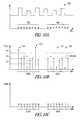
- FIG. 10 ashows an example of rectangular noise with respect to time 460 , wherein the noise occurs during a series of sampling points within two bursts of measurement cycles 462 , 464 .
- Each measurement cycle 462 , 464produces a set of signal sample values, which are representative points in time where measurements are taken of charge induced on a key by a measurement circuit, such as for example those described above.
- the rectangular noisecan disrupt the measurements as explained above, if for example a measurement cycle corresponds to a rising or falling edge of the rectangular noise 466 .
- FIG. 10 billustrates a value of charge measurements for each of these points with respect to time, with a corresponding representation as a numerical count value being shown in FIG. 10 c .
- the average value of the charge detectedis shown on a line 470 , and above and below the average 470 , pre-determined minimum and maximum signal samples 472 , 474 , are set in accordance with an expected range of sample values during the operation of the touch sensor.
- a graphical plot of signal sample valuesis shown, which includes a period 490 which corresponds to a time when a body is present proximate the charge sensor.
- the pre-determined minimum and maximum values 472 , 474are arranged so that the normally expected average signal value is between the minimum and maximum values 472 , 474 and the value of the signal when a touch is detected is greater than the minimum value 472 .
- the averagemay be the mean, median or any other numerical average.
- signal spikes 492may also be present as a result of rectangular noise.
- the samples shown in FIG. 10 bare represented as corresponding relative values in FIG. 10 c , which can be referred to as count values, because, as explained for the touch sensor shown in FIG. 3 , the measurement taken corresponds to the number of time-increments required to discharge the measurement capacitor through a measurement resistor.
- Embodiments of the present techniqueprovide an arrangement for reducing the effects of noise, which can produce erroneous samples of charge measurement from a touch sensor.
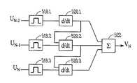
- FIG. 12provides a block diagram of elements involved in reducing the effects of the rectangular noise.
- the present techniqueprocesses the signal sample values produced from a charge measurement circuit within for example a micro-controller and therefore the elements shown in FIG. 12 could in fact form part of the micro-controller 118 of FIG. 3 .
- the samples U n , U n-1 , U n-2are first received by a band pass filter 518 . 1 , 518 . 2 , 518 . 3 after which they are processed respectively by a slew rate limiter 520 . 1 , 520 . 2 , 520 . 3 and then the output of the slew rate limiters 520 . 1 , 520 . 2 , 520 . 3 are fed to an averaging filter 522 .
- the slew rate limitersare cascaded to the effect that the output from the first slew rate limiter 520 . 1 is provided as an input to the second slew rate limiter 520 .
- the signal sample valuesare compared to the accepted range 472 , 474 and are discarded if they fall outside the range of values.
- the signal samplesare then received by the slew rate limiters 520 . 1 , 520 . 2 , 520 . 3 , which use past the samples values U n-1 , U n-2 as well as the present sample value U n to maintain an accumulated relative average value, which should be maintained around the average 470 .
- the rate at which the input value is allowed to changeis adapted in accordance with the relative change between samples.
- the slew rate limiters 520 . 1 , 520 . 2 , 520 . 3It will be appreciated that various techniques could be used to limit the rate of change from one sample to the next.
- Such a limitcould be a linear change, or where two samples exceed a predetermined value, the rate of change can be capped to a fixed increment or decrement so that the slew rate limiter can settle on the average value more quickly.
- a control input 524can be provided to adapt the rate of change provided by the slew rate limiter.
- the samplesare fed to the averaging filter, which performs an averaging of the samples received from each of the slew rate limiters 520 . 1 , 520 . 2 , 520 . 3 .
- the measurement circuitreduces the effect of signal samples, which coincide with impulses of noises or rising or falling edges of noise and therefore cause the values to exceed or fall below an expected range of values. Therefore a more reliable indication that a body is present can be made rather than these noise-induced values causing the touch sensor to be triggered.
- the accepted range of signal sample valueswhich are defined by the maximum and minimum values 472 , 474 shown in FIGS. 10 b and 13 a , are set during a test phase of the touch sensor.
- the test phaseis during power up.
- a set of bursts of measurement cyclesis performed, to generate for each measurement cycle a signal sample value.
- the maximum and minimum values of the signal samples taken during the initialisation phaseare used to define the accepted range of signal sample values.
- the accepted rangedefines the predetermined maximum and minimum values, which are applied to limit the subsequent signal sample values.
- a mean value of the signal sample values, which are generated during the initialisation phaseis determined based on the assumptions that there is no touch during this phase.
- the maximum and minimum values of the accepted rangeare then calculated with reference to this mean value. For example, a pre-determined fraction of this mean value is calculated and this is added to the mean value to determine the maximum value and subtracted from the mean value to produce the minimum value of the accepted range.
- the calibration processcan be automatically repeated, or can be repeated regularly or irregularly according to some deterministic schedule.
- the initialisation phasecould be controlled and initiated by the micro-controller 118 to calculate the accepted range of values to calibrate the touch sensor.
- the initialisation phasecould initiated by the user to calibrate the device.
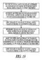
- FIGS. 14 a , 14 b and 15The operation of a touch sensor according to the present technique which includes processing signal sample values to reduce the effects of noise with high frequency components is summarised in the flow diagram shown in FIGS. 14 a , 14 b and 15 .
- the process steps of the method illustrated by the flow diagram shown in FIG. 13 aare summarised as follows:
- a test phasebegins, for example, after power has been supplied to the touch sensor.
- a test phasestarts with the controller performing a series of measurement bursts to calibrate the touch sensor to establish an accepted range of values.
- Each of the measurement burstsis comprised of a plurality of measurement cycles, each cycle generating a signal sample value from the touch sensor.
- S 4The controller then analyses the signal sample values and determines from the signal sample values a steady state or mean value of the signal sample values. The maximum and minimum value of the accepted range of values is then determined with reference to this mean value by adding and subtracting a fraction of the value to itself to form the maximum and minimum values respectively.
- step S 6After step S 4 , the initialisation phase is complete and the processing of the signal sample values, which are generated from bursts of measurement cycles, to detect the presence or absence of a body proximate the touch sensor.
- the signal sample valuesare received by the controller.
- S 8The processing of the signal sample values begins by band pass filtering the signal sample values which lie outside of the accepted range. This can be done by setting values above the maximum to the maximum and values below the minimum to the minimum. Alternatively, any value outside the accepted range can be discarded.
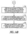
- the method of operation of the touch sensorthen continues via connecting elements A to step S 10 shown in FIG. 14 b.
- the slew rate or rate of change of the signal sample valuesis then limited to be within a determined range.
- the slew rate limitis adapted in accordance with a continuously monitored rate of change of the signal sample values.
- the slew rate limitcan be adapted in accordance with the technique illustrated by the flow diagram shown in FIG. 15 and explained as follows:
- step S 10processing continues after the slew rate limiting in step S 10 , with step S 12 :
- range limitsdo not have to be set at equal offsets from the average.
- the lower limitcould be set having regard to the noise floor as well as or instead of having regard to the average.
Landscapes
- Engineering & Computer Science (AREA)
- General Engineering & Computer Science (AREA)
- Theoretical Computer Science (AREA)
- Human Computer Interaction (AREA)
- Physics & Mathematics (AREA)
- General Physics & Mathematics (AREA)
- Position Input By Displaying (AREA)
- Measurement Of Resistance Or Impedance (AREA)
- Electronic Switches (AREA)
- Investigating Or Analyzing Materials By The Use Of Electric Means (AREA)
Abstract
Description
Claims (20)
Priority Applications (4)
| Application Number | Priority Date | Filing Date | Title |
|---|---|---|---|
| US12/466,230US8378981B2 (en) | 2008-05-19 | 2009-05-14 | Capacitive sensing with high-frequency noise reduction |
| DE102009021844ADE102009021844A1 (en) | 2008-05-19 | 2009-05-19 | Method for sensing presence of body i.e. user's finger, on capacitively charged key of touch sensitive control panel in e.g. TV, involves processing signal sample value, which is outside accepted range so that presence of body is determined |
| TW098116590ATW200951456A (en) | 2008-05-19 | 2009-05-19 | Capacitive sensing with high-frequency noise reduction |
| US13/769,743US20130257795A1 (en) | 2008-05-19 | 2013-02-18 | Capacitive Sensing with High-Frequency Noise Reduction |
Applications Claiming Priority (2)
| Application Number | Priority Date | Filing Date | Title |
|---|---|---|---|
| US5418608P | 2008-05-19 | 2008-05-19 | |
| US12/466,230US8378981B2 (en) | 2008-05-19 | 2009-05-14 | Capacitive sensing with high-frequency noise reduction |
Related Child Applications (1)
| Application Number | Title | Priority Date | Filing Date |
|---|---|---|---|
| US13/769,743ContinuationUS20130257795A1 (en) | 2008-05-19 | 2013-02-18 | Capacitive Sensing with High-Frequency Noise Reduction |
Publications (2)
| Publication Number | Publication Date |
|---|---|
| US20090303198A1 US20090303198A1 (en) | 2009-12-10 |
| US8378981B2true US8378981B2 (en) | 2013-02-19 |
Family
ID=41399879
Family Applications (2)
| Application Number | Title | Priority Date | Filing Date |
|---|---|---|---|
| US12/466,230Active2031-01-21US8378981B2 (en) | 2008-05-19 | 2009-05-14 | Capacitive sensing with high-frequency noise reduction |
| US13/769,743AbandonedUS20130257795A1 (en) | 2008-05-19 | 2013-02-18 | Capacitive Sensing with High-Frequency Noise Reduction |
Family Applications After (1)
| Application Number | Title | Priority Date | Filing Date |
|---|---|---|---|
| US13/769,743AbandonedUS20130257795A1 (en) | 2008-05-19 | 2013-02-18 | Capacitive Sensing with High-Frequency Noise Reduction |
Country Status (3)
| Country | Link |
|---|---|
| US (2) | US8378981B2 (en) |
| CN (1) | CN101644973A (en) |
| TW (1) | TW200951456A (en) |
Cited By (4)
| Publication number | Priority date | Publication date | Assignee | Title |
|---|---|---|---|---|
| US20110115743A1 (en)* | 2009-11-19 | 2011-05-19 | Elan Microelectronics Corporation | Sensing methdo and calibration method for a capacitive touch panel |
| US20110157077A1 (en)* | 2008-06-25 | 2011-06-30 | Bradley Martin | Capacitive sensor system with noise reduction |
| US20130135248A1 (en)* | 2011-11-25 | 2013-05-30 | Senmatrix Semiconductor, Inc. | Voltage-based capacitive touch device and touch sensing method thereof |
| WO2015139113A1 (en)* | 2014-03-17 | 2015-09-24 | Magna Closures Inc. | Method and system for driving a capacitive sensor |
Families Citing this family (32)
| Publication number | Priority date | Publication date | Assignee | Title |
|---|---|---|---|---|
| US9569037B2 (en)* | 2008-05-19 | 2017-02-14 | Atmel Corporation | Capacitive sensing with low-frequency noise reduction |
| TWI420117B (en)* | 2010-02-11 | 2013-12-21 | Novatek Microelectronics Corp | Capacitance sensing apparatus and touch sensing system |
| CN101799734B (en)* | 2010-03-29 | 2012-05-09 | 深圳龙多电子科技有限公司 | Key detection method for capacitive touch screen |
| JP5523191B2 (en)* | 2010-04-30 | 2014-06-18 | 株式会社ジャパンディスプレイ | Display device with touch detection function |
| US8884888B2 (en)* | 2010-08-30 | 2014-11-11 | Apple Inc. | Accelerometer determined input velocity |
| FR2967278B1 (en)* | 2010-11-08 | 2013-06-28 | Nanotec Solution | METHOD FOR DETECTING AN OBJECT OF INTEREST IN A DISTURBED ENVIRONMENT, AND GESTUAL INTERFACE DEVICE USING THE SAME |
| TWI428612B (en) | 2010-12-10 | 2014-03-01 | Elan Microelectronics Corp | A circuit for sensing a capacitance to be measured and a method thereof |
| US20120206399A1 (en)* | 2011-02-10 | 2012-08-16 | Alcor Micro, Corp. | Method and System for Processing Signals of Touch Panel |
| CN102707821B (en)* | 2011-03-28 | 2015-04-22 | 深圳市汇顶科技股份有限公司 | Method and system for de-noising touch detection device |
| KR101239880B1 (en)* | 2011-10-05 | 2013-03-06 | (주)멜파스 | Touch sensing apparatus and method |
| CA2806371C (en)* | 2012-02-17 | 2016-08-09 | Qnx Software Systems Limited | System and method for sample rate adaption |
| US9236861B2 (en) | 2012-07-02 | 2016-01-12 | Stmicroelectronics Asia Pacific Pte Ltd | Capacitive proximity sensor with enabled touch detection |
| CN103970380B (en)* | 2013-02-01 | 2017-05-10 | 晨星半导体股份有限公司 | Capacitive touch system and driving device thereof |
| CN104237773A (en)* | 2013-06-17 | 2014-12-24 | 鸿富锦精密工业(深圳)有限公司 | Touch key testing system and method |
| US9535545B2 (en)* | 2013-06-28 | 2017-01-03 | Atmel Corporation | Common mode noise suppression during hovering and proximity detection |
| US9367190B2 (en)* | 2013-09-13 | 2016-06-14 | Apex Material Technology Corp. | Touch recognition method and system for a capacitive touch apparatus |
| SG11201601478TA (en)* | 2013-10-18 | 2016-03-30 | Univ Nanyang Tech | Circuit arrangement and method of operating the same |
| US9164137B2 (en)* | 2013-12-05 | 2015-10-20 | Parade Technologies, Ltd. | Tunable baseline compensation scheme for touchscreen controllers |
| KR102152727B1 (en)* | 2014-03-03 | 2020-09-08 | 삼성디스플레이 주식회사 | Liquid crystal display device |
| US9600121B2 (en)* | 2014-04-25 | 2017-03-21 | Synaptics Incorporated | Driving sensor electrodes for noise measurement |
| US9454272B2 (en)* | 2014-05-22 | 2016-09-27 | Stmicroelectronics Asia Pacific Pte Ltd | Touch screen for stylus emitting wireless signals |
| US10055045B2 (en)* | 2014-05-31 | 2018-08-21 | Synaptics Incorporated | Current feedback digital charge accumulator |
| US9817530B2 (en)* | 2015-08-31 | 2017-11-14 | Stmicroelectronics Asia Pacific Pte. Ltd. | Electronic device with touchscreen for removing sample subsets and related methods |
| CN108027678B (en) | 2015-09-14 | 2021-09-03 | 辛纳普蒂克斯公司 | Continuous-time anti-aliasing filter for capacitive touch sensing |
| US9971463B2 (en) | 2015-09-29 | 2018-05-15 | Synaptics Incorporated | Row-based sensing on matrix pad sensors |
| US10146371B2 (en)* | 2016-03-29 | 2018-12-04 | Microchip Technology Incorporated | Water robustness and detection on capacitive buttons |
| US10126900B2 (en)* | 2017-04-04 | 2018-11-13 | Synaptics Incorporated | Reduced capacitive baseline shift using null time periods |
| WO2020120541A1 (en)* | 2018-12-12 | 2020-06-18 | Huf Hülsbeck & Fürst Gmbh & Co. Kg | Assembly for a vehicle |
| EP3796140B1 (en)* | 2019-09-18 | 2024-05-22 | Semtech Corporation | Proximity sensor with nonlinear filter and method |
| EP4042568A1 (en)* | 2019-10-08 | 2022-08-17 | Diehl AKO Stiftung & Co. KG | Method for setting a scanning frequency of a capacitive contact switch |
| IT202000006883A1 (en)* | 2020-04-01 | 2021-10-01 | St Microelectronics Srl | SYSTEM AND METHOD OF DETECTION OF PRESENCE IN AN ENVIRONMENT TO BE MONITORED |
| US11550434B2 (en)* | 2020-10-19 | 2023-01-10 | Synaptics Incorporated | Short-term noise suppression |
Citations (12)
| Publication number | Priority date | Publication date | Assignee | Title |
|---|---|---|---|---|
| WO1997023738A1 (en) | 1995-12-26 | 1997-07-03 | Harald Philipp | Charge transfer capacitance sensor |
| WO2000044018A1 (en) | 1999-01-26 | 2000-07-27 | Harald Philipp | Capacitive sensor and array |
| US6466036B1 (en)* | 1998-11-25 | 2002-10-15 | Harald Philipp | Charge transfer capacitance measurement circuit |
| US20050052429A1 (en)* | 2003-08-21 | 2005-03-10 | Harald Philipp | Capacitive position sensor |
| US20050099188A1 (en)* | 2002-07-02 | 2005-05-12 | Baxter Larry K. | Capacitive measurement system |
| US7256714B2 (en)* | 2003-07-11 | 2007-08-14 | Harald Philipp | Keyboard with reduced keying ambiguity |
| US7288946B2 (en)* | 2005-06-03 | 2007-10-30 | Synaptics Incorporated | Methods and systems for detecting a capacitance using sigma-delta measurement techniques |
| US7567240B2 (en)* | 2005-05-31 | 2009-07-28 | 3M Innovative Properties Company | Detection of and compensation for stray capacitance in capacitive touch sensors |
| US20090303203A1 (en) | 2008-05-19 | 2009-12-10 | Esat Yilmaz | Capacitive sensing with low-frequency noise reduction |
| US7663607B2 (en)* | 2004-05-06 | 2010-02-16 | Apple Inc. | Multipoint touchscreen |
| US7755614B2 (en)* | 2005-11-30 | 2010-07-13 | Sunplus Technology Co., Ltd. | Motion detection system and motion detection method |
| US8018440B2 (en)* | 2005-12-30 | 2011-09-13 | Microsoft Corporation | Unintentional touch rejection |
Family Cites Families (29)
| Publication number | Priority date | Publication date | Assignee | Title |
|---|---|---|---|---|
| US5902967A (en)* | 1996-02-09 | 1999-05-11 | Lsi Logic Corporation | Method and apparatus for eliminating an offset signal in an electrostatic digitizing tablet |
| TW408277B (en)* | 1996-11-15 | 2000-10-11 | Alps Electric Co Ltd | Small current detector circuit and locator device using the same |
| KR100595922B1 (en)* | 1998-01-26 | 2006-07-05 | 웨인 웨스터만 | Method and apparatus for integrating manual input |
| US6753853B1 (en)* | 2000-09-29 | 2004-06-22 | Rockwell Automation Technologies, Inc. | Low power dissipation touch plane interface circuit |
| WO2002104004A1 (en)* | 2001-06-18 | 2002-12-27 | Casio Computer Co., Ltd. | Photosensor system and drive control method thereof |
| JP4086523B2 (en)* | 2001-12-04 | 2008-05-14 | キヤノン株式会社 | Image reading apparatus, subject collation system, subject recognition system, and image reading method |
| EP1548409A1 (en)* | 2003-12-23 | 2005-06-29 | Dialog Semiconductor GmbH | Differential capacitance measurement |
| US20050200291A1 (en)* | 2004-02-24 | 2005-09-15 | Naugler W. E.Jr. | Method and device for reading display pixel emission and ambient luminance levels |
| JP4522113B2 (en)* | 2004-03-11 | 2010-08-11 | キヤノン株式会社 | Coordinate input device |
| JP4429047B2 (en)* | 2004-03-11 | 2010-03-10 | キヤノン株式会社 | Coordinate input device, control method therefor, and program |
| US7777501B2 (en)* | 2005-06-03 | 2010-08-17 | Synaptics Incorporated | Methods and systems for sigma delta capacitance measuring using shared component |
| US7902842B2 (en)* | 2005-06-03 | 2011-03-08 | Synaptics Incorporated | Methods and systems for switched charge transfer capacitance measuring using shared components |
| US7945297B2 (en)* | 2005-09-30 | 2011-05-17 | Atmel Corporation | Headsets and headset power management |
| US8279180B2 (en)* | 2006-05-02 | 2012-10-02 | Apple Inc. | Multipoint touch surface controller |
| CN100485596C (en)* | 2006-11-24 | 2009-05-06 | 启攀微电子(上海)有限公司 | Self-adaptive judging method for capacitor type push-button |
| US8031174B2 (en)* | 2007-01-03 | 2011-10-04 | Apple Inc. | Multi-touch surface stackup arrangement |
| US8232970B2 (en)* | 2007-01-03 | 2012-07-31 | Apple Inc. | Scan sequence generator |
| US8049732B2 (en)* | 2007-01-03 | 2011-11-01 | Apple Inc. | Front-end signal compensation |
| US8493330B2 (en)* | 2007-01-03 | 2013-07-23 | Apple Inc. | Individual channel phase delay scheme |
| US7986193B2 (en)* | 2007-01-03 | 2011-07-26 | Apple Inc. | Noise reduction within an electronic device using automatic frequency modulation |
| US7920129B2 (en)* | 2007-01-03 | 2011-04-05 | Apple Inc. | Double-sided touch-sensitive panel with shield and drive combined layer |
| US8040326B2 (en)* | 2007-06-13 | 2011-10-18 | Apple Inc. | Integrated in-plane switching display and touch sensor |
| US8059103B2 (en)* | 2007-11-21 | 2011-11-15 | 3M Innovative Properties Company | System and method for determining touch positions based on position-dependent electrical charges |
| KR101720919B1 (en)* | 2008-02-28 | 2017-03-28 | 쓰리엠 이노베이티브 프로퍼티즈 컴파니 | Touch screen sensor |
| US8035622B2 (en)* | 2008-03-27 | 2011-10-11 | Apple Inc. | SAR ADC with dynamic input scaling and offset adjustment |
| JP5481040B2 (en)* | 2008-04-11 | 2014-04-23 | 株式会社ジャパンディスプレイ | Display device and driving method thereof |
| JP4720857B2 (en)* | 2008-06-18 | 2011-07-13 | ソニー株式会社 | Capacitance type input device and display device with input function |
| US8605037B2 (en)* | 2008-10-21 | 2013-12-10 | Atmel Corporation | Noise reduction in capacitive touch sensors |
| US8031094B2 (en)* | 2009-09-11 | 2011-10-04 | Apple Inc. | Touch controller with improved analog front end |
- 2009
- 2009-05-14USUS12/466,230patent/US8378981B2/enactiveActive
- 2009-05-19CNCN200910203417Apatent/CN101644973A/enactivePending
- 2009-05-19TWTW098116590Apatent/TW200951456A/enunknown
- 2013
- 2013-02-18USUS13/769,743patent/US20130257795A1/ennot_activeAbandoned
Patent Citations (14)
| Publication number | Priority date | Publication date | Assignee | Title |
|---|---|---|---|---|
| WO1997023738A1 (en) | 1995-12-26 | 1997-07-03 | Harald Philipp | Charge transfer capacitance sensor |
| US5730165A (en)* | 1995-12-26 | 1998-03-24 | Philipp; Harald | Time domain capacitive field detector |
| US6466036B1 (en)* | 1998-11-25 | 2002-10-15 | Harald Philipp | Charge transfer capacitance measurement circuit |
| WO2000044018A1 (en) | 1999-01-26 | 2000-07-27 | Harald Philipp | Capacitive sensor and array |
| US6452514B1 (en)* | 1999-01-26 | 2002-09-17 | Harald Philipp | Capacitive sensor and array |
| US20050099188A1 (en)* | 2002-07-02 | 2005-05-12 | Baxter Larry K. | Capacitive measurement system |
| US7256714B2 (en)* | 2003-07-11 | 2007-08-14 | Harald Philipp | Keyboard with reduced keying ambiguity |
| US20050052429A1 (en)* | 2003-08-21 | 2005-03-10 | Harald Philipp | Capacitive position sensor |
| US7663607B2 (en)* | 2004-05-06 | 2010-02-16 | Apple Inc. | Multipoint touchscreen |
| US7567240B2 (en)* | 2005-05-31 | 2009-07-28 | 3M Innovative Properties Company | Detection of and compensation for stray capacitance in capacitive touch sensors |
| US7288946B2 (en)* | 2005-06-03 | 2007-10-30 | Synaptics Incorporated | Methods and systems for detecting a capacitance using sigma-delta measurement techniques |
| US7755614B2 (en)* | 2005-11-30 | 2010-07-13 | Sunplus Technology Co., Ltd. | Motion detection system and motion detection method |
| US8018440B2 (en)* | 2005-12-30 | 2011-09-13 | Microsoft Corporation | Unintentional touch rejection |
| US20090303203A1 (en) | 2008-05-19 | 2009-12-10 | Esat Yilmaz | Capacitive sensing with low-frequency noise reduction |
Cited By (7)
| Publication number | Priority date | Publication date | Assignee | Title |
|---|---|---|---|---|
| US20110157077A1 (en)* | 2008-06-25 | 2011-06-30 | Bradley Martin | Capacitive sensor system with noise reduction |
| US8941394B2 (en)* | 2008-06-25 | 2015-01-27 | Silicon Laboratories Inc. | Capacitive sensor system with noise reduction |
| US20110115743A1 (en)* | 2009-11-19 | 2011-05-19 | Elan Microelectronics Corporation | Sensing methdo and calibration method for a capacitive touch panel |
| US9104277B2 (en)* | 2009-11-19 | 2015-08-11 | Elan Microelectronics Corporation | Sensing method and calibration method for a capacitive touch panel |
| US20130135248A1 (en)* | 2011-11-25 | 2013-05-30 | Senmatrix Semiconductor, Inc. | Voltage-based capacitive touch device and touch sensing method thereof |
| US9063619B2 (en)* | 2011-11-25 | 2015-06-23 | Senmatrix Semiconductor, Inc. | Voltage-based capacitive touch device and touch sensing method thereof |
| WO2015139113A1 (en)* | 2014-03-17 | 2015-09-24 | Magna Closures Inc. | Method and system for driving a capacitive sensor |
Also Published As
| Publication number | Publication date |
|---|---|
| US20130257795A1 (en) | 2013-10-03 |
| CN101644973A (en) | 2010-02-10 |
| TW200951456A (en) | 2009-12-16 |
| US20090303198A1 (en) | 2009-12-10 |
Similar Documents
| Publication | Publication Date | Title |
|---|---|---|
| US8378981B2 (en) | Capacitive sensing with high-frequency noise reduction | |
| US9569037B2 (en) | Capacitive sensing with low-frequency noise reduction | |
| US9448267B2 (en) | Noise measurement in capacitive touch sensors | |
| US8605037B2 (en) | Noise reduction in capacitive touch sensors | |
| US8552995B2 (en) | Sensor and method of sensing | |
| TWI506513B (en) | Method and apparatus to measure self-capacitance using a single pin | |
| US9600124B2 (en) | Sensor and method of sensing | |
| US9229576B2 (en) | Apparatus and method for preventing false touches in touch screen systems | |
| KR101441218B1 (en) | Touch sensor panel negative pixel compensation | |
| US7986153B2 (en) | Method and apparatus for sensing | |
| AU2007248332B2 (en) | Multipoint touch surface controller | |
| KR101837879B1 (en) | Self-capacitance touch detection circuit | |
| US8395395B2 (en) | Noise rejection and parasitic capacitance removal implementations | |
| WO2013126096A1 (en) | Frequency hopping algorithm for capacitance sensing devices | |
| WO2010004867A1 (en) | Electrostatic detection device, information equipment and electrostatic detection method | |
| CN110463041B (en) | Circuit for capacitance detection, touch detection device and terminal equipment | |
| CN102955626B (en) | For method for sensing and the circuit of capacitive sensing equipment | |
| US20160147357A1 (en) | Anti-noise method of touch panel, touch panel and display device | |
| TWI480791B (en) | Touch device and driving method thereof | |
| US9329722B2 (en) | Capacitive touch system and method with auto-calibration | |
| JPS60229132A (en) | Touch sensor | |
| CN113918039B (en) | Signal processing method, device, equipment and storage medium | |
| EP2722985A1 (en) | Method of differential measurement of voltage levels of capacitive change | |
| DE102009021844A1 (en) | Method for sensing presence of body i.e. user's finger, on capacitively charged key of touch sensitive control panel in e.g. TV, involves processing signal sample value, which is outside accepted range so that presence of body is determined | |
| JP2006173699A (en) | Capacitive input device |
Legal Events
| Date | Code | Title | Description |
|---|---|---|---|
| AS | Assignment | Owner name:ATMEL CORPORATION, CALIFORNIA Free format text:ASSIGNMENT OF ASSIGNORS INTEREST;ASSIGNORS:YILMAZ, ESAT;PHILIPP, HARALD;REEL/FRAME:023084/0340;SIGNING DATES FROM 20090804 TO 20090805 Owner name:ATMEL CORPORATION, CALIFORNIA Free format text:ASSIGNMENT OF ASSIGNORS INTEREST;ASSIGNORS:YILMAZ, ESAT;PHILIPP, HARALD;SIGNING DATES FROM 20090804 TO 20090805;REEL/FRAME:023084/0340 | |
| STCF | Information on status: patent grant | Free format text:PATENTED CASE | |
| AS | Assignment | Owner name:MORGAN STANLEY SENIOR FUNDING, INC. AS ADMINISTRATIVE AGENT, NEW YORK Free format text:PATENT SECURITY AGREEMENT;ASSIGNOR:ATMEL CORPORATION;REEL/FRAME:031912/0173 Effective date:20131206 Owner name:MORGAN STANLEY SENIOR FUNDING, INC. AS ADMINISTRAT Free format text:PATENT SECURITY AGREEMENT;ASSIGNOR:ATMEL CORPORATION;REEL/FRAME:031912/0173 Effective date:20131206 | |
| AS | Assignment | Owner name:ATMEL CORPORATION, CALIFORNIA Free format text:TERMINATION AND RELEASE OF SECURITY INTEREST IN PATENT COLLATERAL;ASSIGNOR:MORGAN STANLEY SENIOR FUNDING, INC.;REEL/FRAME:038376/0001 Effective date:20160404 | |
| FPAY | Fee payment | Year of fee payment:4 | |
| AS | Assignment | Owner name:JPMORGAN CHASE BANK, N.A., AS ADMINISTRATIVE AGENT, ILLINOIS Free format text:SECURITY INTEREST;ASSIGNOR:ATMEL CORPORATION;REEL/FRAME:041715/0747 Effective date:20170208 Owner name:JPMORGAN CHASE BANK, N.A., AS ADMINISTRATIVE AGENT Free format text:SECURITY INTEREST;ASSIGNOR:ATMEL CORPORATION;REEL/FRAME:041715/0747 Effective date:20170208 | |
| AS | Assignment | Owner name:JPMORGAN CHASE BANK, N.A., AS ADMINISTRATIVE AGENT, ILLINOIS Free format text:SECURITY INTEREST;ASSIGNORS:MICROCHIP TECHNOLOGY INCORPORATED;SILICON STORAGE TECHNOLOGY, INC.;ATMEL CORPORATION;AND OTHERS;REEL/FRAME:046426/0001 Effective date:20180529 Owner name:JPMORGAN CHASE BANK, N.A., AS ADMINISTRATIVE AGENT Free format text:SECURITY INTEREST;ASSIGNORS:MICROCHIP TECHNOLOGY INCORPORATED;SILICON STORAGE TECHNOLOGY, INC.;ATMEL CORPORATION;AND OTHERS;REEL/FRAME:046426/0001 Effective date:20180529 | |
| AS | Assignment | Owner name:WELLS FARGO BANK, NATIONAL ASSOCIATION, AS NOTES COLLATERAL AGENT, CALIFORNIA Free format text:SECURITY INTEREST;ASSIGNORS:MICROCHIP TECHNOLOGY INCORPORATED;SILICON STORAGE TECHNOLOGY, INC.;ATMEL CORPORATION;AND OTHERS;REEL/FRAME:047103/0206 Effective date:20180914 Owner name:WELLS FARGO BANK, NATIONAL ASSOCIATION, AS NOTES C Free format text:SECURITY INTEREST;ASSIGNORS:MICROCHIP TECHNOLOGY INCORPORATED;SILICON STORAGE TECHNOLOGY, INC.;ATMEL CORPORATION;AND OTHERS;REEL/FRAME:047103/0206 Effective date:20180914 | |
| AS | Assignment | Owner name:JPMORGAN CHASE BANK, N.A., AS ADMINISTRATIVE AGENT, DELAWARE Free format text:SECURITY INTEREST;ASSIGNORS:MICROCHIP TECHNOLOGY INC.;SILICON STORAGE TECHNOLOGY, INC.;ATMEL CORPORATION;AND OTHERS;REEL/FRAME:053311/0305 Effective date:20200327 | |
| AS | Assignment | Owner name:MICROCHIP TECHNOLOGY INC., ARIZONA Free format text:RELEASE BY SECURED PARTY;ASSIGNOR:JPMORGAN CHASE BANK, N.A, AS ADMINISTRATIVE AGENT;REEL/FRAME:053466/0011 Effective date:20200529 Owner name:MICROSEMI STORAGE SOLUTIONS, INC., ARIZONA Free format text:RELEASE BY SECURED PARTY;ASSIGNOR:JPMORGAN CHASE BANK, N.A, AS ADMINISTRATIVE AGENT;REEL/FRAME:053466/0011 Effective date:20200529 Owner name:MICROSEMI CORPORATION, CALIFORNIA Free format text:RELEASE BY SECURED PARTY;ASSIGNOR:JPMORGAN CHASE BANK, N.A, AS ADMINISTRATIVE AGENT;REEL/FRAME:053466/0011 Effective date:20200529 Owner name:ATMEL CORPORATION, ARIZONA Free format text:RELEASE BY SECURED PARTY;ASSIGNOR:JPMORGAN CHASE BANK, N.A, AS ADMINISTRATIVE AGENT;REEL/FRAME:053466/0011 Effective date:20200529 Owner name:SILICON STORAGE TECHNOLOGY, INC., ARIZONA Free format text:RELEASE BY SECURED PARTY;ASSIGNOR:JPMORGAN CHASE BANK, N.A, AS ADMINISTRATIVE AGENT;REEL/FRAME:053466/0011 Effective date:20200529 | |
| AS | Assignment | Owner name:WELLS FARGO BANK, NATIONAL ASSOCIATION, MINNESOTA Free format text:SECURITY INTEREST;ASSIGNORS:MICROCHIP TECHNOLOGY INC.;SILICON STORAGE TECHNOLOGY, INC.;ATMEL CORPORATION;AND OTHERS;REEL/FRAME:053468/0705 Effective date:20200529 | |
| MAFP | Maintenance fee payment | Free format text:PAYMENT OF MAINTENANCE FEE, 8TH YEAR, LARGE ENTITY (ORIGINAL EVENT CODE: M1552); ENTITY STATUS OF PATENT OWNER: LARGE ENTITY Year of fee payment:8 | |
| AS | Assignment | Owner name:WELLS FARGO BANK, NATIONAL ASSOCIATION, AS COLLATERAL AGENT, MINNESOTA Free format text:SECURITY INTEREST;ASSIGNORS:MICROCHIP TECHNOLOGY INCORPORATED;SILICON STORAGE TECHNOLOGY, INC.;ATMEL CORPORATION;AND OTHERS;REEL/FRAME:055671/0612 Effective date:20201217 | |
| AS | Assignment | Owner name:WELLS FARGO BANK, NATIONAL ASSOCIATION, AS NOTES COLLATERAL AGENT, MINNESOTA Free format text:SECURITY INTEREST;ASSIGNORS:MICROCHIP TECHNOLOGY INCORPORATED;SILICON STORAGE TECHNOLOGY, INC.;ATMEL CORPORATION;AND OTHERS;REEL/FRAME:057935/0474 Effective date:20210528 | |
| AS | Assignment | Owner name:MICROSEMI STORAGE SOLUTIONS, INC., ARIZONA Free format text:RELEASE BY SECURED PARTY;ASSIGNOR:JPMORGAN CHASE BANK, N.A., AS ADMINISTRATIVE AGENT;REEL/FRAME:059333/0222 Effective date:20220218 Owner name:MICROSEMI CORPORATION, ARIZONA Free format text:RELEASE BY SECURED PARTY;ASSIGNOR:JPMORGAN CHASE BANK, N.A., AS ADMINISTRATIVE AGENT;REEL/FRAME:059333/0222 Effective date:20220218 Owner name:ATMEL CORPORATION, ARIZONA Free format text:RELEASE BY SECURED PARTY;ASSIGNOR:JPMORGAN CHASE BANK, N.A., AS ADMINISTRATIVE AGENT;REEL/FRAME:059333/0222 Effective date:20220218 Owner name:SILICON STORAGE TECHNOLOGY, INC., ARIZONA Free format text:RELEASE BY SECURED PARTY;ASSIGNOR:JPMORGAN CHASE BANK, N.A., AS ADMINISTRATIVE AGENT;REEL/FRAME:059333/0222 Effective date:20220218 Owner name:MICROCHIP TECHNOLOGY INCORPORATED, ARIZONA Free format text:RELEASE BY SECURED PARTY;ASSIGNOR:JPMORGAN CHASE BANK, N.A., AS ADMINISTRATIVE AGENT;REEL/FRAME:059333/0222 Effective date:20220218 | |
| AS | Assignment | Owner name:ATMEL CORPORATION, ARIZONA Free format text:RELEASE BY SECURED PARTY;ASSIGNOR:JPMORGAN CHASE BANK, N.A., AS ADMINISTRATIVE AGENT;REEL/FRAME:059262/0105 Effective date:20220218 | |
| AS | Assignment | Owner name:MICROSEMI STORAGE SOLUTIONS, INC., ARIZONA Free format text:RELEASE BY SECURED PARTY;ASSIGNOR:WELLS FARGO BANK, NATIONAL ASSOCIATION, AS NOTES COLLATERAL AGENT;REEL/FRAME:059358/0001 Effective date:20220228 Owner name:MICROSEMI CORPORATION, ARIZONA Free format text:RELEASE BY SECURED PARTY;ASSIGNOR:WELLS FARGO BANK, NATIONAL ASSOCIATION, AS NOTES COLLATERAL AGENT;REEL/FRAME:059358/0001 Effective date:20220228 Owner name:ATMEL CORPORATION, ARIZONA Free format text:RELEASE BY SECURED PARTY;ASSIGNOR:WELLS FARGO BANK, NATIONAL ASSOCIATION, AS NOTES COLLATERAL AGENT;REEL/FRAME:059358/0001 Effective date:20220228 Owner name:SILICON STORAGE TECHNOLOGY, INC., ARIZONA Free format text:RELEASE BY SECURED PARTY;ASSIGNOR:WELLS FARGO BANK, NATIONAL ASSOCIATION, AS NOTES COLLATERAL AGENT;REEL/FRAME:059358/0001 Effective date:20220228 Owner name:MICROCHIP TECHNOLOGY INCORPORATED, ARIZONA Free format text:RELEASE BY SECURED PARTY;ASSIGNOR:WELLS FARGO BANK, NATIONAL ASSOCIATION, AS NOTES COLLATERAL AGENT;REEL/FRAME:059358/0001 Effective date:20220228 | |
| AS | Assignment | Owner name:MICROSEMI STORAGE SOLUTIONS, INC., ARIZONA Free format text:RELEASE BY SECURED PARTY;ASSIGNOR:WELLS FARGO BANK, NATIONAL ASSOCIATION, AS NOTES COLLATERAL AGENT;REEL/FRAME:059863/0400 Effective date:20220228 Owner name:MICROSEMI CORPORATION, ARIZONA Free format text:RELEASE BY SECURED PARTY;ASSIGNOR:WELLS FARGO BANK, NATIONAL ASSOCIATION, AS NOTES COLLATERAL AGENT;REEL/FRAME:059863/0400 Effective date:20220228 Owner name:ATMEL CORPORATION, ARIZONA Free format text:RELEASE BY SECURED PARTY;ASSIGNOR:WELLS FARGO BANK, NATIONAL ASSOCIATION, AS NOTES COLLATERAL AGENT;REEL/FRAME:059863/0400 Effective date:20220228 Owner name:SILICON STORAGE TECHNOLOGY, INC., ARIZONA Free format text:RELEASE BY SECURED PARTY;ASSIGNOR:WELLS FARGO BANK, NATIONAL ASSOCIATION, AS NOTES COLLATERAL AGENT;REEL/FRAME:059863/0400 Effective date:20220228 Owner name:MICROCHIP TECHNOLOGY INCORPORATED, ARIZONA Free format text:RELEASE BY SECURED PARTY;ASSIGNOR:WELLS FARGO BANK, NATIONAL ASSOCIATION, AS NOTES COLLATERAL AGENT;REEL/FRAME:059863/0400 Effective date:20220228 | |
| AS | Assignment | Owner name:MICROSEMI STORAGE SOLUTIONS, INC., ARIZONA Free format text:RELEASE BY SECURED PARTY;ASSIGNOR:WELLS FARGO BANK, NATIONAL ASSOCIATION, AS NOTES COLLATERAL AGENT;REEL/FRAME:059363/0001 Effective date:20220228 Owner name:MICROSEMI CORPORATION, ARIZONA Free format text:RELEASE BY SECURED PARTY;ASSIGNOR:WELLS FARGO BANK, NATIONAL ASSOCIATION, AS NOTES COLLATERAL AGENT;REEL/FRAME:059363/0001 Effective date:20220228 Owner name:ATMEL CORPORATION, ARIZONA Free format text:RELEASE BY SECURED PARTY;ASSIGNOR:WELLS FARGO BANK, NATIONAL ASSOCIATION, AS NOTES COLLATERAL AGENT;REEL/FRAME:059363/0001 Effective date:20220228 Owner name:SILICON STORAGE TECHNOLOGY, INC., ARIZONA Free format text:RELEASE BY SECURED PARTY;ASSIGNOR:WELLS FARGO BANK, NATIONAL ASSOCIATION, AS NOTES COLLATERAL AGENT;REEL/FRAME:059363/0001 Effective date:20220228 Owner name:MICROCHIP TECHNOLOGY INCORPORATED, ARIZONA Free format text:RELEASE BY SECURED PARTY;ASSIGNOR:WELLS FARGO BANK, NATIONAL ASSOCIATION, AS NOTES COLLATERAL AGENT;REEL/FRAME:059363/0001 Effective date:20220228 | |
| AS | Assignment | Owner name:MICROSEMI STORAGE SOLUTIONS, INC., ARIZONA Free format text:RELEASE BY SECURED PARTY;ASSIGNOR:WELLS FARGO BANK, NATIONAL ASSOCIATION, AS NOTES COLLATERAL AGENT;REEL/FRAME:060894/0437 Effective date:20220228 Owner name:MICROSEMI CORPORATION, ARIZONA Free format text:RELEASE BY SECURED PARTY;ASSIGNOR:WELLS FARGO BANK, NATIONAL ASSOCIATION, AS NOTES COLLATERAL AGENT;REEL/FRAME:060894/0437 Effective date:20220228 Owner name:ATMEL CORPORATION, ARIZONA Free format text:RELEASE BY SECURED PARTY;ASSIGNOR:WELLS FARGO BANK, NATIONAL ASSOCIATION, AS NOTES COLLATERAL AGENT;REEL/FRAME:060894/0437 Effective date:20220228 Owner name:SILICON STORAGE TECHNOLOGY, INC., ARIZONA Free format text:RELEASE BY SECURED PARTY;ASSIGNOR:WELLS FARGO BANK, NATIONAL ASSOCIATION, AS NOTES COLLATERAL AGENT;REEL/FRAME:060894/0437 Effective date:20220228 Owner name:MICROCHIP TECHNOLOGY INCORPORATED, ARIZONA Free format text:RELEASE BY SECURED PARTY;ASSIGNOR:WELLS FARGO BANK, NATIONAL ASSOCIATION, AS NOTES COLLATERAL AGENT;REEL/FRAME:060894/0437 Effective date:20220228 | |
| MAFP | Maintenance fee payment | Free format text:PAYMENT OF MAINTENANCE FEE, 12TH YEAR, LARGE ENTITY (ORIGINAL EVENT CODE: M1553); ENTITY STATUS OF PATENT OWNER: LARGE ENTITY Year of fee payment:12 |