US8378908B2 - Array antenna for measurement-while-drilling - Google Patents
Array antenna for measurement-while-drillingDownload PDFInfo
- Publication number
- US8378908B2 US8378908B2US11/685,040US68504007AUS8378908B2US 8378908 B2US8378908 B2US 8378908B2US 68504007 AUS68504007 AUS 68504007AUS 8378908 B2US8378908 B2US 8378908B2
- Authority
- US
- United States
- Prior art keywords
- elements
- array antenna
- antenna
- dipole
- produce
- Prior art date
- Legal status (The legal status is an assumption and is not a legal conclusion. Google has not performed a legal analysis and makes no representation as to the accuracy of the status listed.)
- Expired - Fee Related, expires
Links
Images


Classifications
- G—PHYSICS
- G01—MEASURING; TESTING
- G01V—GEOPHYSICS; GRAVITATIONAL MEASUREMENTS; DETECTING MASSES OR OBJECTS; TAGS
- G01V3/00—Electric or magnetic prospecting or detecting; Measuring magnetic field characteristics of the earth, e.g. declination, deviation
- G01V3/18—Electric or magnetic prospecting or detecting; Measuring magnetic field characteristics of the earth, e.g. declination, deviation specially adapted for well-logging
- G01V3/26—Electric or magnetic prospecting or detecting; Measuring magnetic field characteristics of the earth, e.g. declination, deviation specially adapted for well-logging operating with magnetic or electric fields produced or modified either by the surrounding earth formation or by the detecting device
- G01V3/28—Electric or magnetic prospecting or detecting; Measuring magnetic field characteristics of the earth, e.g. declination, deviation specially adapted for well-logging operating with magnetic or electric fields produced or modified either by the surrounding earth formation or by the detecting device using induction coils
- G—PHYSICS
- G01—MEASURING; TESTING
- G01V—GEOPHYSICS; GRAVITATIONAL MEASUREMENTS; DETECTING MASSES OR OBJECTS; TAGS
- G01V3/00—Electric or magnetic prospecting or detecting; Measuring magnetic field characteristics of the earth, e.g. declination, deviation
- G01V3/18—Electric or magnetic prospecting or detecting; Measuring magnetic field characteristics of the earth, e.g. declination, deviation specially adapted for well-logging
- G01V3/30—Electric or magnetic prospecting or detecting; Measuring magnetic field characteristics of the earth, e.g. declination, deviation specially adapted for well-logging operating with electromagnetic waves
- H—ELECTRICITY
- H01—ELECTRIC ELEMENTS
- H01Q—ANTENNAS, i.e. RADIO AERIALS
- H01Q1/00—Details of, or arrangements associated with, antennas
- H01Q1/04—Adaptation for subterranean or subaqueous use
- H—ELECTRICITY
- H01—ELECTRIC ELEMENTS
- H01Q—ANTENNAS, i.e. RADIO AERIALS
- H01Q1/00—Details of, or arrangements associated with, antennas
- H01Q1/12—Supports; Mounting means
- H01Q1/22—Supports; Mounting means by structural association with other equipment or articles
- H—ELECTRICITY
- H01—ELECTRIC ELEMENTS
- H01Q—ANTENNAS, i.e. RADIO AERIALS
- H01Q1/00—Details of, or arrangements associated with, antennas
- H01Q1/40—Radiating elements coated with or embedded in protective material
- H—ELECTRICITY
- H01—ELECTRIC ELEMENTS
- H01Q—ANTENNAS, i.e. RADIO AERIALS
- H01Q21/00—Antenna arrays or systems
- H01Q21/06—Arrays of individually energised antenna units similarly polarised and spaced apart
- H01Q21/20—Arrays of individually energised antenna units similarly polarised and spaced apart the units being spaced along or adjacent to a curvilinear path
- H01Q21/205—Arrays of individually energised antenna units similarly polarised and spaced apart the units being spaced along or adjacent to a curvilinear path providing an omnidirectional coverage
- H—ELECTRICITY
- H01—ELECTRIC ELEMENTS
- H01Q—ANTENNAS, i.e. RADIO AERIALS
- H01Q9/00—Electrically-short antennas having dimensions not more than twice the operating wavelength and consisting of conductive active radiating elements
- H01Q9/04—Resonant antennas
- H01Q9/16—Resonant antennas with feed intermediate between the extremities of the antenna, e.g. centre-fed dipole
- H01Q9/20—Two collinear substantially straight active elements; Substantially straight single active elements
Definitions
- This inventionis directed toward measurements made within a borehole, and more particularly directed toward an electromagnetic measurement-while-drilling (MWD) or a logging-while-drilling (LWD) system comprising at least one array antenna.
- MWDelectromagnetic measurement-while-drilling
- LWDlogging-while-drilling
- Electromagnetic borehole measurementsare also used to determine a wide range of geophysical parameters of interest including the location of bed boundaries, the dip of formations intersecting by the borehole, and anisotropy of material intersected by the borehole. Electromagnetic measurements are also used to “steer” the drilling of the borehole.
- Borehole instruments, or borehole “tools”, used to obtain EM measurementstypically comprise one or more antennas or transmitting coils which are energized by an alternating electrical current. Resulting EM energy interacts with the surrounding formation and borehole environs by propagation or by induction of currents within the borehole environs. One or more receivers respond to this EM energy or current. A single coil or antenna can serve as both a transmitter and a receiver. Parameters of interest, such as those listed above, are determined from the response of the one or more receivers. Response of one or more receivers within the borehole apparatus may be telemetered to the surface of the earth via conveyance means that include a wireline or a drill string equipped with a borehole telemetry system. Alternately, the response of one or more receivers can be stored within the borehole tool for subsequent retrieval at the surface of the earth.
- Standard induction and wave propagation EM toolsare configured with transmitter and receiver coils with their magnetic moments aligned with the tool axis. More recently, induction tools with three axis coils and wave propagation MWD or LWD tools with antennas (coils) whose magnetic moments are not aligned with the tool axis are being produced and used. These MWD or LWD propagation tools, with antenna dipole axes tilted with respect to the tool axis, can distinguish resistivity differences as a function of tool azimuth. Tools with coils aligned with the tool axis cannot distinguish resistivity changes as a function of tool azimuthal angle.
- the azimuthal resistivity response feature of an electromagnetic MWD or LWD toolis most useful in direction or “geosteering” the drilling direction of a well in a formation of interest. More specifically, the distance and direction from the tool to a bed (such as shale) bounding the formation of interest, or water interfaces within the formation of interest, can be determined from the azimuthal resistivity response of the tool. Using this information, the drill bit can be directed or “steered”, in real time, so as to avoid penetrating non hydrocarbon bearing formations with the borehole.
- Prior art MWD or LWD tools that make azimuthal EM measurementsemploy a combination of separate axially aligned antennas and antennas whose magnetic moments are tilted at an angle with respect to the tool axis.
- Such toolsfor example, are described in U.S. Pat. No. 6,476,609 issued to Bittar, and U.S. Pat. No. 6,297,639 issued to Clark et al. These tools have a fixed response azimuth, and can only preferentially determine resistivity or distance to a bed on one side of the tool, or at fixed azimuth angles relative to the tool. The tools must be rotated in order to respond to or “see” resistivity differences or boundaries on all sides of the borehole.
- the antennas with different dipole orientations located at different axial spacings along the length of the toollack a common dipole origin point. This fact precludes vector addition of the dipole moments to form a new dipole moment, in any direction, with the same origin point. Multiple antennas at differing axial spacings also increase tool production and maintenance cost, and further reduces mechanical tool strength.
- U.S. Pat. No. 6,181,138 issued to Hagiwaradescribes an antenna design that has three independent, co-located, antenna coils with a common tilt angle.
- Co-located in this contextmeans having dipole moments whose origins are coincident and tilt angle is the angle between the tool axis and the dipole moment of the antenna coil.
- These antenna coils acting togethercan direct a transmitter or receiver resultant antenna dipole moment in any direction.
- This antenna designplaces coils around a drilling collar in a region of reduced diameter or “necked down” region. It is well known in the art that reducing the outer diameter of a drilling collar weakens it in that area and causes the collar to be more prone to mechanical failure.
- Non-conductive coverings presently used in the artsuch as fiberglass, rubber, epoxy, ceramics or plastic are subject to wear due to abrasion which occurs between the tool and the borehole wall, and are not as strong as the collar material. Because the non-conducting region must encircle the collar it is likely to contact the borehole wall unless the collar is further “necked down” causing further weakness. An extreme penalty is paid by “necking down” drilling tubulars. It is well known to those skilled in the art that reducing the outer diameter of a cylindrical member reduces the torsional and bending stiffness proportional to the forth power of the radius. For example, reducing the diameter of a 5 inch (12.7 centimeter) tubular to 4 inches (10.2 centimeters) reduces the torsional and bending stiffness by 59%.
- the Chen and Barber designmust somehow be modified to divert the mud away from the coils and the openings in the tool body thereby adding complexity and cost to the manufacture of the tool.
- Another problem encountered in embodying the Chen and Barber design as an MWD or LWD systemis that, owing to the required non-conductive covering which is disposed around the circumference of the tool, the coils are not protected from abrasion which occurs between the tool and the borehole wall during drilling.
- a crossed dipole antenna for wireline applicationsis described in U.S. Pat. No. 5,406,206 issued to Safinya et al.
- This patentdescribes a slot or cavity antenna with crossed magnetic dipoles and a dielectric backing.
- This systemis purported to operate in the frequency range of 200 to 2000 MHz and as such would be only suitable as a pad mounted device which contacts the borehole wall during operation.
- the antenna described in the present patentcan operate at frequencies below 10 MHz and does not require contact with the borehole wall for operation.
- the antenna of the present patentuses a thin plate of ferrite underneath current carrying wires and is much more efficient at lower frequencies
- U.S. Pat. No. 5,530,358 issued to Wisler et alThis antenna is integrated into a drilling tubular affording maximum strength and abrasion resistance, but it is only a single axial dipole antenna.
- One of the key components of the Wisler et al systemis the antenna wire pathways disposed beneath the surface of the drilling tubular surface to avoid any abrasion and so as not to reduce the strength of the tubular. Protection of the coils and their non-conducting covering in the Chen and Barber design may be partially accomplished by reducing the radius or “necking down” the drilling tubular in the antenna region similar to the Hagiwara design. However “necking down” in the region of the antennas will significantly reduce the tubular strength in that region, and the tool will therefore be more prone to failure downhole. Although more robust, the Wisler patent does not teach varying the direction of the antenna dipole moment.
- the present inventionis a MWD or LWD wave propagation resistivity logging system using an antenna comprising an array of cross-dipole elements with each element having cross magnetic dipoles.
- the array antenna conceptprovides a robust design that does not significantly reduce the structural integrity of a borehole drilling tubular or “mandrel” in which it is disposed.
- the array antenna and associated control and process methodologiesare ideally suited for MWD or LWD systems.
- the disclosed apparatus and methodscan, however, be applied to tools conveyed into the well borehole by other means such as wireline, tubing, slick line, and pump-down.
- the array designis robust is integrated into a drill collar body, and, in one preferred embodiment, requires only four “slots” in the form recesses in the drill collar per array antenna.
- the antenna elementsare disposed in these recesses in the body of the drill collar, and are thereby protected by from abrasion and other damage caused by the rotation or longitudinal movement of the drill string to which the tool is attached. Because the recesses do not extend around the periphery of the drill collar, they do not significantly reduce the strength of the drill collar.
- the antenna elementscomprise a plate composed of a soft ferromagnetic material crossed or looped by separate and independent current carrying conductors, such as wires, in two or more directions forming preferably a bi-directional or crossed magnetic dipole.
- the soft ferromagnetic materialis preferably ferrite.
- the wires and elements of the arraymay be individually operated or connected together to produce a triaxial common origin magnetic dipole antenna.
- the versatility provided by the antenna designallows the antenna to operate in other useful modes, such as a quadrupole mode, circularly polarized mode, or a longitudinal current mode.
- a tool comprising a plurality of axially spaced cross dipole array antennascan be operated in a variety of modes, which are briefly summarized in the following paragraphs.
- the toolcan be operated as a standard, multi-spaced, fully compensated, propagation type resistivity tool by using only the z components of the antenna elements, wherein the z components are coincident with the major axis of the tool.
- Standard, multi-spaced, fully compensated propagation resistivity toolsare known in the art and are described in many references including the previously referenced Wisler patent.
- the toolcan be operated as an azimuthal resistivity tool by using only the x and y components of the array antenna, where the x and y components are traverse or perpendicular to the major axis of the tool.
- the azimuthal measurementis made with respect to a specific point on the face of the tool.
- the previously referenced Runge patent and the Chen and Barber patentalso describe methods of producing (or preferentially sensing) a transverse magnetic dipole.
- the toolcan be operated as an azimuthally steered resistivity tool by combining the x and y antenna components to point the magnetic dipoles of the transmitters and/or receivers in any azimuthal direction.
- the azimuthcan be chosen to be a function of borehole azimuth and thus be pointed in any direction (e.g. up or down) and independent of the tool azimuthal orientation.
- the toolcan be operated as a variable depth of investigation azimuthal tool by varying the direction of the dipole moment in the x, y and z direction and with respect to inclination relative to the tool.
- the toolcan be operated to produce or sense a magnetic quadrupole field by directing magnetic dipoles moments in opposite directions on at least two antenna elements.
- the toolcan be operated to produce a circularly or elliptically polarized field by energizing the crossed wires on an antenna element with signals typically 90 degrees out of phase with one another.
- the circularly polarized signalcan be detected by receiving signals on antenna element wire and combining the signals with one shifted by typically 90 degrees of phase.
- the toolcan be operated to produce or sense a longitudinal current on a drill collar exterior by directing the magnetic dipoles generated or detected by antenna elements in the same azimuthal direction around the periphery of the collar.
- FIG. 1shows an azimuthal cross section view of an antenna element disposes in a recess on the outer surface of a tool housing
- FIG. 2is a cross-section of a typical wireway housing the wire
- FIG. 3is an axial cross sectional view of an antenna element that was shown in azimuthal cross sectional in FIG. 1 ;
- FIG. 4is a top view of an antenna element that is shown in cross sectional in FIGS. 1 and 3 ;
- FIG. 5Ashows cross sectional views depicting a first wiring scheme for an antenna element
- FIG. 5Bshows cross sectional views depicting a second wiring scheme for an antenna element
- FIG. 6Ashows a perspective view of a preferred embodiment comprising four antenna arrays spaced axially on a tool
- FIG. 6Bis cross sectional view of one of the arrays is shown in FIG. 6A ;
- FIG. 7Ashows a particular quad array antenna in which individual elements of the array are wired as in shown in FIG. 5B ;
- FIG. 7Bshows a front view of the antenna of FIG. 7A disposed in a tool
- FIG. 7Cshows a back view of the antenna of FIG. 7A disposed in a tool
- FIG. 8Ashows a quad array antenna in which individual elements of the array are wired as shown in FIG. 5A ;
- FIG. 8Bshows a front view of the antenna of FIG. 8A disposed in a tool
- FIG. 8Cshows a back view of the antenna of FIG. 8A disposed in a tool
- FIG. 9Ashows an antenna embodiment comprising three separate wire pairs that produce three orthogonal magnetic dipole moments with a common origin
- FIG. 9Bshows a front view of the antenna of FIG. 9A disposed in a tool
- FIG. 9Cshows a back view of the antenna of FIG. 9A disposed in a tool
- FIG. 10Adefines a coordinate system to illustrate modes of antenna operation
- FIG. 10Bshows the four antenna elements producing dipole moments 92 in a tip to tail fashion around the periphery of a conducting mandrel or drill collar;
- FIG. 10Cshows the directions of the dipole moments for the triaxial common origin antenna
- FIG. 10Dshows a single element of the array with two axes in a lateral and in a longitudinal direction
- FIG. 10Eshows dipole directions that will generate a field with a quadrupole moment
- FIG. 10Fshows the dipole moment orientations that will simulate a single axial dipole at the center of the quad antenna array
- FIG. 11is a functional diagram of various elements comprising the downhole assembly of the resistivity logging system
- FIG. 12illustrates all of the major components of the resistivity logging system in a MWD environment
- FIG. 13Ashows a tool comprising a drill collar housing and four axially disposed quad antenna arrays
- FIG. 13Bis a contour plot illustrating the response of the tool when the tilt angles of the transmitter arrays are zero;
- FIG. 13Cis a contour plot illustrating the response of the tool when the tilt angles of the transmitter arrays are 30 degrees;
- FIG. 13Dis a contour plot illustrating the response of the tool when the tilt angles of the transmitter arrays are 60 degrees.
- FIG. 14illustrates a use of the axial current mode in which the antenna elements are operated in an azimuthal direction as shown in FIG. 10B .
- the present inventionis described herein as a MWD or LWD wave propagation resistivity logging system comprising an integrated dipole array antenna.
- MWDMWD
- LWDLWD wave propagation resistivity logging system
- the array antennacomprises several array elements that can act alone or in combination to produce a variety of measurement modes. Each array element is a cross-dipole element having cross magnetic dipoles.
- the dipole antenna componentsare used as both transmitters and receivers. Subsequent descriptions of antenna operation in a transmission mode apply equally to antenna operation in a reception mode. It will be realized by those familiar with the art that all of the magnetic dipole based antennas discussed in this disclosure can operate in either a transmission mode or a reception mode.
- magnetic dipolesare generated by controlling, preferably with a numerically controlled oscillator (NCO) cooperating with a processor, the phase and amplitude of the current that energizes a particular wire in an antenna element.
- NCOnumerically controlled oscillator
- the direction of transmissionis controlled by the geometry of the wire and element.
- the net direction of the magnetic dipole generated by a combination of simultaneous energizing currentsis a resultant dipole comprising the vector sum of the individual magnetic dipoles.
- signals received on a particular wire in an antenna element due to magnetic coupling with a transmitted fieldwill be proportional to the vector projection of the transmitted field magnetic vector onto the preferential direction of the particular antenna element and wire combination.
- This preferential directionis determined by the geometry of the antenna element.
- the signals from a group of these wires, each responding preferably to a magnetic field in a particular direction,may be combined by weighting each signal and summing to produce a signal that has a response to another preferential direction.
- the combinationis preferably controlled by a processor.
- controlling the signal input to the wires in a transmission mode or weighting the output signal from the wires in a reception modeare equivalent in the sense that the preferential direction of an antenna dipole moment may be controlled.
- FIG. 1shows an azimuthal cross section view of a cross-dipole antenna element disposed in a recess 23 on the outer surface of a mandrel serving as a housing for a tool 20 .
- the mandrelis preferably a drill collar comprising a conduit 22 through which drilling fluid flows.
- the tool 20is shown disposed within a borehole 32 defined by a borehole wall 28 and penetrating an earth formation 29 .
- the mounted antenna elementcomprises a plate composed of high magnetic permeability material 30 disposed in the recess 23 . Owing to its low loss and high magnetic permeability characteristics, the preferred material composing the plate is ferrite, and in what follows this material will be referred to as ferrite.
- wires 16 and 12cross the surface of the ferrite plate 30 at right angles, but do not contact each other or the ferrite electrically.
- the wiresare communicated from the recess to a circuit hatch (see FIGS. 7C , 8 C and 9 C) via wireways, illustrated with broken lines, below the outer surface of the tool 20 .
- the wireway for wire 16is illustrated at 16 a .
- the wireway for wire 12is indicated at 12 a in FIG. 3 . Only one wire 12 is shown in FIG. 3 , but a plurality of wires may be disposed within the wireway in the same manner.
- the ferrite plate 30is covered by a non-conducting covering layer 18 , such as a ceramic, in which the wires 12 and 16 are disposed.
- a non-conducting covering layer 18such as a ceramic, in which the wires 12 and 16 are disposed.
- the term “non-conducting” materialwill be used to include partially conducting material or any covering material 18 which does not significantly attenuate an electromagnetic signal. Because most ferrite withstands compression very well but shears easily, the non-conducting layer 18 can allow the ferrite plate 30 to experience downhole pressure as long as the pressure is applied evenly to all surfaces of the non-conducting material 18 and the abutted ferrite plate 30 . Industry standard methods of protecting the ferrite 30 from pressure with a non-conducting “hatch” may be used but are not shown.
- a hard-facing wear element 17 fabricated from a material such as tungsten carbideis shown at a larger diameter than the non-conducting material 18 to protect the antenna element from damage downhole.
- the hard-facing wear element 17is preferably fabricated with a beveled lip 17 a to reduce torque shear encountered when the tool 20 is rotated in the borehole 32 .
- a current in the wire 12will produce a magnetic dipole field perpendicular to the tool axis and tangent to the tool surface with its origin at the center of the element. This axis of the antenna element will be termed “lateral”.
- a current in the wire 16will produce a magnetic dipole field parallel to the tool axis and also tangent to the tool surface with its origin also at the center of the element. This axis will be termed “longitudinal”.
- FIG. 2is a cross-section of a typical wireway housing the wire 16 . Only one wire is shown but several wires may be contained in the wireway housing.
- the wirewaycomprises a groove 15 machined into the outer surface of the tool 20 .
- the groove 15is covered with a metal cap 19 that is secured to the tool by welds 21 .
- the wires feeding the antenna elementsare protected from abrasion that occurs when the drilling tools contact the borehole wall.
- FIG. 3is an axial cross sectional view of an antenna element that was shown in azimuthal cross sectional in FIG. 1 .
- the wireway 12 a housing the wire 12 within the wall of the tool 20is clearly illustrated.
- FIG. 3also illustrates wires 12 and 16 disposed at right angles across the surface of the ferrite plate 30 which, in turn, is disposed in the recess 23 along with the covering layer 18 .
- FIG. 4is a top view of an antenna element that is shown in cross sectional in FIGS. 1 and 3 . This view clearly shows wires 12 and 16 crossing at right angles, with wire 12 being parallel to the major axis of the tool 20 . It is noted that both wires 12 and 16 are disposed within the non-conducting material 18 , as clearly shown in FIGS. 1 and 3 .
- FIGS. 5A and 5Bshow cross sectional views depicting two wiring schemes for an antenna element.
- FIG. 5Ashows wire or wires 38 exiting a wireway 38 a on the left into the recess 23 in the tool 20 , going across the surface of the ferrite plate 30 , and exiting into the wireway 38 a on the right.
- Current flowing the wire or wires 38 going left to rightwill produce a magnetic field that is perpendicular to the plane of the cross sectional illustration.
- Current flow in a wire 36 that is perpendicular to plane of the cross sectional illustrationwill produce a magnetic field in the left to right axis.
- FIG. 5Bshows a pair of wires 40 , preferably twisted together to avoid losses, entering a collar recess 23 from a wireway 40 a in the tool 20 .
- the wiresare wrapped around the ferrite plate 30 with one or more turns (only one shown) as illustrated at 44 .
- the magnetic field produced by a current in the wires 40 entering from the leftwill produce a magnetic field perpendicular to the cross sectional illustration.
- a second loop 42which is perpendicular to the first loop 44 , is also wrapped around the ferrite plate 30 . As with previous illustrations, more than one turn may be used.
- a current in the second loop 42will produce a magnetic field in the left to right axis.
- the two currents in the loops 42 and 44can be individually controlled and will produce magnetic fields with axes parallel to the outer surface of the tool 20 at the position of the antenna element. One will preferably be perpendicular or lateral to the tool axis and the other will be parallel to the tool axis or longitudinal. A combination of two wireways and wrapping around the ferrite plate may also be used, but is not shown. Also the wires forming the loops 42 and 44 can be replaced with flat conductors, especially the wires (not shown) that go between the ferrite plate 30 and the body of the tool 20 which is typically a steel drill collar. With flat conductors, the downhole pressure load on the ferrite 30 and the abutting non-conductor 18 can be evenly distributed to avoid cracking the ferrite.
- cross-dipole antenna element shown in FIGS. 1 through 5Bdepict a particular crossed dipole design, other designs such as non-orthogonal wiring and more than two axes are obvious to one skilled in the art.
- FIG. 6Ashows a perspective view of a preferred embodiment comprising four array antennas 10 spaced axially on a tool 20 , which is a drill collar.
- the drilling fluid flow conduit of the collar 20is shown at 22 .
- Each array 10comprises four crossed dipole antenna elements 50 with previously discussed components disposed within tool recesses 23 . These antenna element components 50 are electrically exposed to the borehole environs.
- the four elements 50 comprising each array 10are preferably equally spaced in azimuth at 90 degree centers and are disposed at the same axial position on the drill collar 10 .
- the embodiment of four cross-dipole elements comprising a single array antennawill be referred to as a “quad array”.
- the wear elements of hard-facing materialsuch as tungsten carbide are again identified with the numeral 17 .
- the location of the antennasis that of a single spaced borehole compensated propagation resistivity tool where the upper and lower antennas are transmitters and the middle two antennas are receivers.
- FIG. 6BA cross sectional view of one of the quad array antennas 10 is shown in FIG. 6B , and more clearly illustrates the azimuthal deposition of the wear elements 17 with tapered lips 17 a and the “electrically exposed” antenna elements identified at 50 .
- FIG. 7Ashows a particular quad array antenna in which individual elements of the array are wired as in shown in FIG. 5B with twisted pair wiring going to each axis of each element.
- the pairs of wiresare labeled X 1 , X 2 , Y 1 , Y 2 , Z 1 , Z 2 , Z 3 , and Z 4 .
- pairs X 2 , Y 2 , and Z 2are identified at 64 a , 62 a and 66 a , respectively, and form loops 64 , 62 and 66 , respectively.
- the “front” of the antennais identified by the labeled arrow.
- X 1 and X 2 wire pairscontrol the lateral axes of two antenna elements positioned on opposite sides of a tool.
- Wire pairs Y 1 and Y 2control the lateral axes of two antenna elements also positioned on opposite sides of the same tool but rotated 90 degrees of tool azimuth from X 1 and X 2 .
- Z 1 , Z 2 , Z 3 , and Z 4 wire pairscontrol the longitudinal axes of the four antenna elements in this antenna.
- FIG. 7Billustrates the quad array antenna 10 , embodied as shown in FIG. 7A , and disposed in the wall of a drill collar 20 comprising a conduit 22 through which drilling fluid flows.
- the orientation of the array antennais the same as shown in FIG. 7A , therefore the illustration of FIG. 7B will be referred to as a “front view”.
- Two axially coincident recessesare shown covered with the non-conducting material 18 and disposed at typically 90 degree azimuthal spacing on the outer surface of the collar 20 .
- the ferrite plates 30are disposed beneath the plates of non-conducting material 18 (see FIGS. 1 , 3 , 5 A and 5 B).
- Portions of the antenna wire componentsare disposed in wireways within the material 18 .
- a portion of the loop 62is shown as an example. Broken lines conceptually illustrate the disposition of the remaining portions of other antenna components in wireways the wall of the collar 20 , with the wireway for the wire from the loop 62 being shown at 62 a
- FIG. 7Cagain illustrates the quad array antenna 10 within the collar 20 , wherein the collar has been rotated 180 degrees from the position shown in FIG. 7B .
- This illustrationwill be referred to as the “back view”.
- portions of the dipole antenna componentsare disposed in wireways within the non-conducting material 18 .
- Portions of the loops 64 and 66are shown as examples.
- Broken linesagain conceptually illustrate the disposition of the remaining portions of other antenna components in wireways the wall of the collar 20 , with wire from the loop 66 being shown at 66 a .
- Wires from the dipole componentsconverge at a connection box covered by a hatch 70 .
- the connection boxcontains electrical connections and tuning circuits for these dipole antenna components.
- FIG. 8Ashows a quad array antenna 10 in which individual elements of the array are wired as shown in FIG. 5A and in FIGS. 1 and 3 . More specifically, individual elements of the array are wired as in shown in FIG. 5A with single wiring going to each axis of each element. As in the embodiment shown in FIGS. 7A , 7 B and 7 C, each of the two axes of each element is individually controllable.
- the pairs of wiresare labeled X 1 , X 2 , Y 1 , Y 2 , Z 1 , Z 2 , Z 3 , and Z 4 as shown in FIG. 8A .
- Y 2 , Z 2 , Z 4 Y 1 , Z 1 , Y 2are identified at 72 , 73 , 79 , 76 , 77 , and 78 , respectively.
- the “front” of the antennais again identified by the labeled arrow.
- FIG. 8Billustrates the quad array antenna 10 , embodied as shown in FIG. 8A , and disposed in the wall of a drill collar 20 .
- the orientation of the array antennais the same as shown in FIG. 8A , therefore the illustration of FIG. 8B will be referred to as a “front view”.
- Two axially coincident recessesare again shown covered with the non-conducting material 18 and disposed at typically 90 degree azimuthal spacing on the outer surface of the collar 20 .
- portions of the dipole antenna componentsare disposed in wireways within the material 18 . More specifically, wires 73 , 74 , 72 and 75 are illustrated.
- the broken linesagain conceptually illustrate the disposition of the remaining portions the antenna components in wireways the wall of the collar 20 .
- FIG. 8Cillustrates the quad array antenna 10 shown in FIGS. 8A and 8B , wherein the collar 20 has been rotated 180 degrees from the position shown in FIG. 8B .
- This illustrationonce again will be referred to as the “back view”.
- Portions of the antenna componentsare again disposed in wireways within the non-conducting material 18 . Examples are shown at 76 , 77 , 78 and 79 .
- Broken linesonce again conceptually illustrate the disposition of the remaining portions of other antenna components in wireways. Wires from the antenna components again converge at the connection box covered by the hatch 70 .
- FIG. 9Ashows another method of wiring a quad array antenna 10 .
- the wires 112 , 114 and 116 used to control the elementsare labeled X, Y, and Z, respectively.
- the front of the arrayis again denoted with an arrow.
- a common origin triaxial antennathere are measurement advantages afforded by a common origin triaxial antenna. Common origin triaxial applications disclosed in these patents can be achieved with the antenna embodiment shown in FIG. 9A .
- An advantage of the common origin triaxial antenna embodiment of this disclosure over the prior artis the robust design that affords both strength and abrasion protection for the antenna elements.
- FIG. 9Billustrates the array antenna 10 , embodied as shown in FIG. 9A , and disposed in the wall of a drill collar 20 .
- the orientation of the array antennais the same as shown in FIG. 9A , therefore the illustration of FIG. 9B will be referred to as a “front view”.
- Two axially coincident recessesare shown covered with the non-conducting material 18 and disposed at typically 90 degree azimuthal spacing on the outer surface of the collar 20 .
- the wires 112 , 114 and 116are shown disposed in the non-conducting material 18 and in wireways within the tool 20 , as illustrated conceptually with broken lines.
- FIG. 9Cillustrates the array antenna 10 shown in FIGS. 9A and 9B , wherein the collar 20 has been rotated 180 degrees from the position shown in FIG. 9B . Again following convention, this illustration is referred to as the “back view”. Wires 112 , 114 and 116 are again shown disposed in the non-conducting material 18 and in connecting tool body wireways that converge at the connection box covered by the hatch 70 .
- FIGS. 9A , 9 B and 9 Cand the related Cartesian coordinate system 119 a .
- Current in the X pairwill energize the lateral axis of the two antenna elements labeled 118 a and 118 c with the same signal. This will produce a resultant magnetic dipole perpendicular to the tool axis (arrow 119 in FIG. 9A ) and perpendicular to a plane containing the tool axis and the centers of the ferrite elements 30 (covered with non-conducting material 18 ) which the X labeled wire 112 crosses.
- the resultant dipolewill be the sum of two dipoles produced on opposite sides of the collar 20 and thereby have an origin at the geometric center of the antenna array 10 .
- a current in the Y pairwill energize the lateral axes of the two antenna elements labeled 118 b and 118 d and thereby produce a resultant magnetic dipole identical to a current in the X pair, but rotated 90 degrees in azimuth about the Z axis which is coincident with the tool axis 119 .
- the resultant magnetic dipolewill be the sum of the two dipoles on opposite sides of the collar 20 and thereby have an origin at the geometric center of the antenna array 10 .
- a current in the Z pairwill energize the longitudinal axes of the four antenna elements 118 a , 118 b , 118 c and 118 d and thereby produce a resultant magnetic dipole in a direction coinciding with the tool axis 119 .
- This resultant magnetic momentwill also have an origin at the geometric center of the antenna array 10 .
- FIGS. 10B-10Fshow the direction of dipole moments for a quad array antenna 10 , in several different modes of operation, with respect to the coordinate system defined in FIG. 10A .
- the mandrel 20which is preferably a conducting drill collar, is not shown for clarity, but represented conceptually with a circle 91 defining the outer surface of the structure. It will be recognized that more than one mode may be produced and detected by a particular array antenna, such as the quad array antenna. These modes may be operated sequentially or may be operated simultaneously by frequency using methods known to those skilled in the art. Thus, a single tool can simulate multiple tools in a single measure period.
- FIG. 10Bshows the four antenna elements producing dipole moments 92 in a tip to tail fashion around the periphery of a conducting mandrel or drill collar 91 .
- this antenna modewill launch (or detect) an axial current in a collar as illustrated conceptually with the arrow 93 .
- the use of an antenna that launches or detects an axial current on the surface of an MWD toolis known in the art and will not be discussed in detail. Possible uses of this mode are data communication among MWD tools in the same drill string using the longitudinal current as the medium, and resistivity measurements including at the bit measurements in which the conduction of the axial current into the formation is measured.
- FIG. 10Cshows the directions of the dipole moments 85 for the triaxial common origin antenna.
- the axial or longitudinal dipolesare all pointed in the same direction (upward) and the lateral dipoles on opposite sides of the tool are pointed in the same direction. More specifically two lateral dipoles point in the X direction and the other two dipoles point in the Y direction. It will be obvious to one skilled in the art that when the Z direction dipole moments of the four antenna elements have the same magnitude and phase, the resultant dipole moment has an origin in the center of the tool and is also in the Z direction.
- antenna arrays described hereinemploy the preferred four element array, it should be obvious to one skilled in the art that array antennas with fewer than four or more than four elements can be constructed and combined to produce equivalent or similar results.
- FIG. 10Dshows a single element of the array with its two axes 87 in a lateral and in a longitudinal direction.
- this modemay be used to probe into the formation in a manner similar to a ground penetrating radar and to detect formation changes and anisotropy. It is well known that the use of circular polarization in ground penetrating radar applications is useful to increase the signal to noise ratio of the received signal.
- FIG. 10Eshows dipole directions that will generate a field with a quadrupole moment.
- the dipoles 89 shownare on opposite sides of the collar 91 and in opposite directions.
- the uses of this modeare also not discussed in detail but may include measurement of resistivity anisotropy.
- FIG. 10Fshows the dipole moment orientations 88 that will simulate a single axial dipole at the center of the quad antenna array, thus the quad antennas can be embodied to simulate traditional electromagnetic propagation resistivity tool antennas.
- FIG. 11is a functional diagram of various elements comprising the downhole tool assembly 100 of the MWD resistivity logging system.
- the diagramis conceptual in nature, used for purposes of illustrating the operation of the system, and is not intended to limit the apparatus and methods of the system to specific mechanical configurations or electronic circuit designs.
- components of the cross dipole array antenna 10are disposed in the wall of a drill collar 20 , wherein the drill collar wall serves as a pressure housing for the dowhhole portion of the wave propagation resistivity MWD logging system.
- the dipole antenna components of the array antenna 10 , collar housing 20 , connection box and hatch cover 70 (see FIGS. 7C , 8 C and 9 C), tuning circuits 124 a , and related electrical connectors 133are conceptually illustrated in FIG. 11 as a subsection 155 .
- the subsection 155is electrically connected to an electronics subsection 160 by means of coaxial cables 137 .
- the electronics subsection 160comprises a receiver control circuit 144 and/or a transmitter control circuit 142 .
- the antennamay be operated as a transmitter or as a receiver or may be sequenced between the two. Operation of the receiver control circuit 144 and the transmitter control circuit 142 is directed by appropriate signals from a processor 146 .
- Control signals from an external sourcesuch as an inclinometer or a magnetometer or even a clock, can be input through an input device into the processor 146 .
- This external source and cooperating input deviceare illustrated conceptually at 162 with a broken line connecting the processor 146 .
- Processor outputis input into a borehole telemetry subsection 170 .
- the borehole telemetry subsectioncan be one of a variety of MWD or LWD telemetry systems known in the art.
- Information from the electronics subsection 160is stored in tool memory (not shown) typically disposed within the electronics section, or telemetered to the surface of the earth as shown at 169 via the borehole telemetry subsection 170 , or stored in tool memory and telemetered to the surface. Data stored in the tool memory or telemetered to the surface may be compressed to accommodate limited memory and telemetry band width. Conversely, information can be telemetered from the surface to the downhole tool assembly 100 of the resistivity logging system.
- the subsection 155 and the electronics subsection 160are powered by a power supply 166 . The functionality of elements and components shown in FIG. 11 will be discussed in the following section of this disclosure.
- FIG. 12illustrates all of the major components of the resistivity logging system in a MWD environment.
- the downhole tool assembly 100 of the systemshown disposed in a borehole 32 , is operationally connected to a drill string 172 by means of a suitable connector 171 .
- the lower end of the downhole assembly 100is terminated by a drill bit 180 .
- a rotary drilling rigknown in the art and represented conceptually at 190 , rotates the drill string 172 , downhole assembly 100 , and drill bit 180 thereby advancing the borehole 32 .
- FIG. 12illustrates all of the major components of the resistivity logging system in a MWD environment.
- the downhole tool assembly 100 of the systemshown disposed in a borehole 32 , is operationally connected to a drill string 172 by means of a suitable connector 171 .
- the lower end of the downhole assembly 100is terminated by a drill bit 180 .
- a rotary drilling rigknown in the art and represented conceptually at 190 , rotate
- the downhole assembly 100comprises a subsection 155 containing at least one array antenna 10 and related tuning circuits 124 a , an electronics subsection 160 , a power supply subsection 166 and a borehole telemetry subsection 170 .
- Each of these subsectionsis preferably disposed within the wall of a drill collar 20 that serves as a pressure housing for the downhole assembly 100 .
- Data measured by the subsection 155 and processed by the electronics subsection 160are telemetered via the borehole telemetry subsection 170 to the surface of the earth and received by a surface telemetry unit 192 .
- a surface processor 194cooperates with the surface telemetry unit 192 to handle and optionally perform additional mathematical operations upon the data received from the downhole assembly 100 .
- Process dataare output to a recorder 196 for storage and optionally for output as a function of measured depth thereby forming a “log” 198 of one or more parameters of interest. It should be understood that information, such as signals to vary the direction of drilling or signals to vary the operation of the at least one array antenna 10 in the subsection 155 , can be transmitted from the surface to the downhole assembly via the surface telemetry unit 192 and the cooperating borehole telemetry subsection 170 .
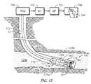
- a deviated borehole 32is illustrated.
- the borehole 32penetrates an upper formation 129 b and is then deviated so that the borehole is advanced within a formation 129 a , which is bounded at the bottom by a formation 129 c .
- formation 129 awould be a hydrocarbon bearing formation such as an oil saturated sand.
- the upper formation 129 b and the lower formation 129 cwould typically be non hydrocarbon producing formations, such as shales.
- the objective of the deviated drilling operationis to advance the borehole 32 within the producing formation, defined by bed boundaries 129 b and 129 a , thereby maximizing production from the producing formation.
- the use of the one or more array antennas 10 operating to produce azimuthally dependent resistivity measurementsmay be used to geosteer within the producing formation.
- Concepts and examples of azimuthally dependent resistivity tools used for geosteeringare described in prior art, including the previously referenced U.S. Pat. No. 6,181,138 issued to Hagawara, U.S. Pat. No. 6,476,609 issued to Bittar, and U.S. Pat. No. 6,297,639 issued to Clark et al., which are hereby incorporated by reference.
- FIGS. 13A-13DA particular embodiment of a tool employing quad array antennas to produce an azimuthally dependent measurement that has a variable depth of investigation is illustrated in FIGS. 13A-13D .
- FIG. 13Ashows a downhole assembly tool 100 comprising a tool housing 20 shown as a drill collar and four axially disposed quad antenna arrays 10 A, 10 B, 10 C and 10 D.
- the arrows 202 a , 202 b , 202 c and 202 dconceptually represent the resultant dipole moments of four quad antennas 10 A, 10 B, 10 C and 10 D, respectively.
- each quad antenna arraymay produce a dipole moment in any direction.
- the outer quad antenna arrays 10 A and 10 Bare operated as transmitters with the resulting dipole moments 202 a and 202 b , respectively, chosen to have a variable tilt angle 204 and 206 , respectively, with respect to the tool axis 119 .
- the inner antennas 10 C and 10 Dare operated as receivers with their dipole moments 202 c and 202 d , respectively, parallel to the tool housing axis 119 .
- the centers 210 and 212 of the transmitter antenna arrays 10 A and 10 B, respectively,are each axially spaced 46 inches (117 centimeters) from the axial center 208 of the tool housing 20 .
- the centers 214 and 216 of the receiver antenna arrays 10 C and 10 D, respectively,are each axially spaced 4.0 inches (10.2 centimeters) from the center 208 of the tool housing 20 .
- the toolis preferably operated as a standard 400 kilohertz (kHz) borehole compensated propagation resistivity tool, which is known in the art.
- the tilt angles of the transmitterscan, however, be changed. More specifically, the tilt angles 204 and 206 of the transmitter arrays 10 A and 10 B can be changed thereby varying the region of sensitivity of the tool.
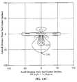
- FIG. 13Bis a computer generated contour plot illustrating the phase response of the tool 100 when the tilt angles 204 and 206 are zero. This is the configuration of the standard borehole compensated propagation resistivity tool. Identifying numbers for the four quad antennas 10 A, 10 B, 10 C and 10 D illustrated in FIG. 13A have been omitted for clarity in FIG. 13B as well as in subsequent FIGS. 13C and 13D .
- the abscissa and ordinateare in inches, with the center 208 of the tool at coordinate (0,0).
- the lighter shaded areasillustrate the regions where the tool is most sensitive to changes in resistivity. As an example, the tool is more sensitive in the area defined by contour 234 than in the area defined by contour 238 . Sensitivity above and below the tool 100 is seen to be the same, as in known in the art for standard borehole compensated propagation resistivity tools.
- FIG. 13Cis a computer generated contour plot illustrating the response of the tool 100 when the tilt angles 204 and 206 are 30 degrees. Again, the lighter shaded areas illustrate the regions where the tool is most sensitive to changes in resistivity. As in FIG. 13B , the tool is more sensitive in the area defined by contour 234 than in the area defined by contour 238 . When the tilt angles are increased from zero to 30 degrees, it can be seen that the tool is more sensitive to regions below the tool than to regions above the tool.
- FIG. 13Dis a computer generated contour plot illustrating the response of the tool 100 when the tilt angles 204 and 206 are 60 degrees.
- the lighter shaded areasillustrate the regions where the tool is most sensitive to changes in resistivity, with the tool being more sensitive in the area defined by contour 234 than in the area defined by contour 238 .
- the phase response of the toolis also more sensitive to regions below the tool, but sensitivity does not extend as far out radially as with the 30 degree tilt shown in FIG. 13C .
- Variations of the tilt angles 204 and 206have thereby produced a variable depth of investigation.
- resultant dipoles 202 a and 202 b as shown in FIG. 13Acan be controlled electronically. Since these resultant dipoles define the tilt angles 204 and 206 , the depth of investigation of the tool 100 can be varied without physically modifying elements within the quad antenna array.
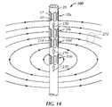
- FIG. 14illustrates a use of the axial current mode in which the antenna elements are operated in an azimuthal direction as shown in FIG. 10B .
- the bottom antenna array 10 Bis operated as a transmitter and the two center antenna arrays 10 D and 10 C are operated as receivers.
- the frequency of the transmitted signalis typically between 0.1 kHz and 20 kHz.
- the transmitter array 10 B, energizing antenna elements in a tip to tail fashion as shown in FIG. 10Bwill induce an voltage longitudinally across the transmitter array. This voltage will, in turn, produce a longitudinal current in the collar as illustrated conceptually by the arrows 270 .
- the current 270proceeds longitudinally, part of it will be returned through borehole mud and formation (not shown) to points below the transmitter 10 B as shown in FIG. 14 .
- some of the currentwill exit the tool collar 100 between the two receivers 10 D and 10 C, as illustrated conceptually by the current lines 272 .
- the two receivers 10 D and 10 Cmay be operated as current sensors by sensing the dipole elements in a fashion shown in FIG. 10B .
- a measure of the current exiting between the two receiverswill be achieved by subtracting the current 270 in the tool collar 100 at receiver 10 D from the current in the tool collar at receiver 10 C.
- a voltage measurementmay then be made at a point 274 between receivers 10 D and 10 C and a ground point internal to the collar (not shown).
- the wires to the voltage measurement pointsmay be routed within wireways, such as those depicted by dotted lines in FIG. 7C , and connected to the surface of the tool collar 100 in a standard way, such as through a bulkhead connector (not shown).
- the resistivity of the formationmay then be measured by dividing the voltage of the region between the receivers by the longitudinal current difference sensed between the two receivers, and multiplying by a constant known in the industry as a “tool” constant.
- the tool constantmay then be determined by immersing the tool in water of a known conductivity.
- Each antennais comprised of an array of crossed magnetic dipole elements. These elements may have at least two axes and may be individually controlled or may be wired together to produce a variety of operating modes, including but not limited to a common origin triaxial antenna.
Landscapes
- Physics & Mathematics (AREA)
- Life Sciences & Earth Sciences (AREA)
- Engineering & Computer Science (AREA)
- Remote Sensing (AREA)
- Electromagnetism (AREA)
- Environmental & Geological Engineering (AREA)
- Geology (AREA)
- General Life Sciences & Earth Sciences (AREA)
- General Physics & Mathematics (AREA)
- Geophysics (AREA)
- Geophysics And Detection Of Objects (AREA)
Abstract
Description
Claims (70)
Priority Applications (4)
| Application Number | Priority Date | Filing Date | Title |
|---|---|---|---|
| US11/685,040US8378908B2 (en) | 2007-03-12 | 2007-03-12 | Array antenna for measurement-while-drilling |
| CA2619623ACA2619623C (en) | 2007-03-12 | 2008-02-05 | Array antenna for measurement-while-drilling |
| GB0802527AGB2447537B (en) | 2007-03-12 | 2008-02-12 | Array antenna for measurement-while-drilling |
| NO20081245ANO342852B1 (en) | 2007-03-12 | 2008-03-10 | Group antenna and method of measurement while drilling |
Applications Claiming Priority (1)
| Application Number | Priority Date | Filing Date | Title |
|---|---|---|---|
| US11/685,040US8378908B2 (en) | 2007-03-12 | 2007-03-12 | Array antenna for measurement-while-drilling |
Publications (2)
| Publication Number | Publication Date |
|---|---|
| US20080224707A1 US20080224707A1 (en) | 2008-09-18 |
| US8378908B2true US8378908B2 (en) | 2013-02-19 |
Family
ID=39247480
Family Applications (1)
| Application Number | Title | Priority Date | Filing Date |
|---|---|---|---|
| US11/685,040Expired - Fee RelatedUS8378908B2 (en) | 2007-03-12 | 2007-03-12 | Array antenna for measurement-while-drilling |
Country Status (4)
| Country | Link |
|---|---|
| US (1) | US8378908B2 (en) |
| CA (1) | CA2619623C (en) |
| GB (1) | GB2447537B (en) |
| NO (1) | NO342852B1 (en) |
Cited By (19)
| Publication number | Priority date | Publication date | Assignee | Title |
|---|---|---|---|---|
| US20100176813A1 (en)* | 2007-04-16 | 2010-07-15 | Matthieu Simon | Antenna of an electromagnetic probe for investigating geological formations |
| US20110221443A1 (en)* | 2008-11-24 | 2011-09-15 | Halliburton Energy Services, Inc. | High Frequency Dielectric Measurement Tool |
| US20140253131A1 (en)* | 2013-03-05 | 2014-09-11 | Ce Liu | Apparatus and Method for Directional Resistivity Measurement While Drilling Using Slot Antenna |
| US9035843B1 (en) | 2014-06-12 | 2015-05-19 | King Fahd University Of Petroleum And Minerals | Ferrite-loaded, Fabry-Perot cavity antenna |
| US9201159B2 (en) | 2010-06-16 | 2015-12-01 | Halliburton Energy Services, Inc. | Nuclear magnetic resonance logging tool having an array of antennas |
| US20160084982A1 (en)* | 2013-10-03 | 2016-03-24 | Halliburton Energy Services, Inc. | Pipe and borehole imaging tool with multi-component conformable sensors |
| WO2016209270A1 (en)* | 2015-06-26 | 2016-12-29 | Halliburton Energy Services, Inc. | Antennas for wellbore logging tools and methods of manufacture |
| US20170033464A1 (en)* | 2015-07-31 | 2017-02-02 | At&T Intellectual Property I, Lp | Radial antenna and methods for use therewith |
| US9562987B2 (en) | 2011-04-18 | 2017-02-07 | Halliburton Energy Services, Inc. | Multicomponent borehole radar systems and methods |
| CN107112624A (en)* | 2015-01-16 | 2017-08-29 | 哈里伯顿能源服务公司 | Drill collar mountable spool antenna with coil and ferrite slot |
| US9851467B2 (en) | 2006-08-08 | 2017-12-26 | Halliburton Energy Services, Inc. | Tool for azimuthal resistivity measurement and bed boundary detection |
| US9880307B2 (en) | 2013-10-24 | 2018-01-30 | Baker Hughes Incorporated | Induction logging sensor |
| US9921333B2 (en) | 2015-06-26 | 2018-03-20 | Halliburton Energy Services, Inc. | Antenna assembly using ferrites within an interposed sleeve for wellbore logging tools |
| US10024996B2 (en) | 2015-10-12 | 2018-07-17 | Halliburton Energy Services, Inc. | Collocated coil antennas incorporating a symmetric soft magnetic band |
| US10048399B2 (en) | 2015-10-20 | 2018-08-14 | Halliburton Energy Services, Inc. | Soft magnetic bands for tilted coil antennas |
| US10260292B2 (en) | 2015-01-16 | 2019-04-16 | Halliburton Energy Services, Inc. | Dedicated wireways for collar-mounted bobbin antennas |
| US10358911B2 (en) | 2012-06-25 | 2019-07-23 | Halliburton Energy Services, Inc. | Tilted antenna logging systems and methods yielding robust measurement signals |
| US10641087B2 (en) | 2015-10-28 | 2020-05-05 | Halliburton Energy Services, Inc. | Inductive cavity sensors for resistivity tools |
| US20210126337A1 (en)* | 2019-10-28 | 2021-04-29 | Bench Tree Group, Llc | Electromagnetic tool using slotted point dipole antennas |
Families Citing this family (59)
| Publication number | Priority date | Publication date | Assignee | Title |
|---|---|---|---|---|
| US20080224706A1 (en) | 2006-11-13 | 2008-09-18 | Baker Hughes Incorporated | Use of Electrodes and Multi-Frequency Focusing to Correct Eccentricity and Misalignment Effects on Transversal Induction Measurements |
| US7554328B2 (en)* | 2006-11-13 | 2009-06-30 | Baker Hughes Incorporated | Method and apparatus for reducing borehole and eccentricity effects in multicomponent induction logging |
| WO2008076130A1 (en) | 2006-12-15 | 2008-06-26 | Halliburton Energy Services, Inc. | Antenna coupling component measurement tool having rotating antenna configuration |
| US20090230969A1 (en)* | 2007-02-19 | 2009-09-17 | Hall David R | Downhole Acoustic Receiver with Canceling Element |
| US7994791B2 (en)* | 2007-02-19 | 2011-08-09 | Schlumberger Technology Corporation | Resistivity receiver spacing |
| US8198898B2 (en)* | 2007-02-19 | 2012-06-12 | Schlumberger Technology Corporation | Downhole removable cage with circumferentially disposed instruments |
| US8436618B2 (en) | 2007-02-19 | 2013-05-07 | Schlumberger Technology Corporation | Magnetic field deflector in an induction resistivity tool |
| US8395388B2 (en) | 2007-02-19 | 2013-03-12 | Schlumberger Technology Corporation | Circumferentially spaced magnetic field generating devices |
| GB2468734B (en) | 2008-01-18 | 2012-08-08 | Halliburton Energy Serv Inc | Em-guided drilling relative to an existing borehole |
| US9182509B2 (en)* | 2008-07-10 | 2015-11-10 | Schlumberger Technology Corporation | System and method for generating true depth seismic surveys |
| US8368403B2 (en)* | 2009-05-04 | 2013-02-05 | Schlumberger Technology Corporation | Logging tool having shielded triaxial antennas |
| US9134449B2 (en)* | 2009-05-04 | 2015-09-15 | Schlumberger Technology Corporation | Directional resistivity measurement for well placement and formation evaluation |
| RU2392644C1 (en)* | 2009-05-21 | 2010-06-20 | Открытое акционерное общество "Научно-производственное предприятие по геофизическим работам, строительству и закачиванию скважин" (ОАО НПП "ГЕРС") | Compensated electromagnetic logging device during slim hole drilling |
| US9366780B2 (en)* | 2009-10-08 | 2016-06-14 | Precision Energy Services, Inc. | Steerable magnetic dipole antenna for measurement while drilling applications |
| US8604796B2 (en)* | 2009-10-08 | 2013-12-10 | Precision Energy Services, Inc. | Steerable magnetic dipole antenna for measurement-while-drilling applications |
| US9140817B2 (en)* | 2009-10-08 | 2015-09-22 | Precision Energy Services, Inc. | Steerable magnetic dipole antenna for measurement-while-drilling applications |
| US8471563B2 (en)* | 2009-10-08 | 2013-06-25 | Precision Energy Services, Inc. | Steerable magnetic dipole antenna for measurement while drilling applications |
| US20110210741A1 (en)* | 2010-03-01 | 2011-09-01 | Suedow Gustav Goeran Mattias | Structure for magnetic field sensor for marine geophysical sensor streamer |
| CN105204077A (en)* | 2010-04-29 | 2015-12-30 | 普拉德研究及开发股份有限公司 | Gain-corrected measurements |
| CA2800148C (en) | 2010-06-29 | 2015-06-23 | Halliburton Energy Services, Inc. | Method and apparatus for sensing elongated subterranean anomalies |
| US9529113B2 (en) | 2010-08-31 | 2016-12-27 | Halliburton Energy Services, Inc. | Method and apparatus for downhole measurement tools |
| KR20130141527A (en)* | 2010-10-15 | 2013-12-26 | 시리트 엘엘씨 | Surface scattering antennas |
| EP3410160A1 (en)* | 2011-04-18 | 2018-12-05 | Halliburton Energy Services Inc. | Method for real-time downhole processing and detection of bed boundary for geosteering application |
| US9500762B2 (en) | 2011-09-19 | 2016-11-22 | Precision Energy Services, Inc. | Borehole resistivity imager using discrete energy pulsing |
| GB201120350D0 (en)* | 2011-11-25 | 2012-01-04 | Go Science Ltd | Annular vehicle with dipole antenna |
| US9181798B2 (en) | 2012-03-29 | 2015-11-10 | Schlumberger Technology Corporation | Removable modular antenna assembly for downhole applications |
| CA2895018C (en)* | 2012-12-31 | 2019-02-12 | Halliburton Energy Services, Inc. | Deep azimuthal system with multi-pole sensors |
| BR112015012050A2 (en) | 2012-12-31 | 2019-12-17 | Halliburton Energy Services Inc | formation imaging with multipole antennas |
| US9385435B2 (en) | 2013-03-15 | 2016-07-05 | The Invention Science Fund I, Llc | Surface scattering antenna improvements |
| WO2014201297A2 (en) | 2013-06-12 | 2014-12-18 | Well Resolutions Technology | Apparatus and methods for making azimuthal resistivity measurements |
| CA2916275C (en) | 2013-06-18 | 2021-10-12 | Well Resolutions Technology | Modular resistivity sensor for downhole measurement while drilling |
| WO2015050884A1 (en)* | 2013-10-03 | 2015-04-09 | Halliburton Energy Services, Inc. | Multi-layer sensors for downhole inspection |
| US9923271B2 (en) | 2013-10-21 | 2018-03-20 | Elwha Llc | Antenna system having at least two apertures facilitating reduction of interfering signals |
| US9647345B2 (en) | 2013-10-21 | 2017-05-09 | Elwha Llc | Antenna system facilitating reduction of interfering signals |
| MX356612B (en) | 2013-10-30 | 2018-06-06 | Halliburton Energy Services Inc | Apparatus and method of processing multi-component induction data. |
| US9935375B2 (en) | 2013-12-10 | 2018-04-03 | Elwha Llc | Surface scattering reflector antenna |
| US10236574B2 (en) | 2013-12-17 | 2019-03-19 | Elwha Llc | Holographic aperture antenna configured to define selectable, arbitrary complex electromagnetic fields |
| US10431899B2 (en) | 2014-02-19 | 2019-10-01 | Kymeta Corporation | Dynamic polarization and coupling control from a steerable, multi-layered cylindrically fed holographic antenna |
| US9448305B2 (en) | 2014-03-26 | 2016-09-20 | Elwha Llc | Surface scattering antenna array |
| US9843103B2 (en) | 2014-03-26 | 2017-12-12 | Elwha Llc | Methods and apparatus for controlling a surface scattering antenna array |
| US10830039B2 (en)* | 2014-04-03 | 2020-11-10 | Baker Hughes Holdings Llc | Downhole tri-axial induction electromagnetic tool |
| US9711852B2 (en) | 2014-06-20 | 2017-07-18 | The Invention Science Fund I Llc | Modulation patterns for surface scattering antennas |
| US9882288B2 (en) | 2014-05-02 | 2018-01-30 | The Invention Science Fund I Llc | Slotted surface scattering antennas |
| US9853361B2 (en) | 2014-05-02 | 2017-12-26 | The Invention Science Fund I Llc | Surface scattering antennas with lumped elements |
| US10446903B2 (en) | 2014-05-02 | 2019-10-15 | The Invention Science Fund I, Llc | Curved surface scattering antennas |
| US9790784B2 (en)* | 2014-05-20 | 2017-10-17 | Aps Technology, Inc. | Telemetry system, current sensor, and related methods for a drilling system |
| US9976413B2 (en) | 2015-02-20 | 2018-05-22 | Aps Technology, Inc. | Pressure locking device for downhole tools |
| BR112017019282A2 (en)* | 2015-04-16 | 2018-05-02 | Halliburton Energy Services Inc | apparatus and method |
| KR20190087292A (en) | 2015-06-15 | 2019-07-24 | 시리트 엘엘씨 | Method and system for communication using beam forming antenna |
| RU2595278C1 (en)* | 2015-07-29 | 2016-08-27 | Общество с ограниченной ответственностью "ГЕРС Технолоджи" | Complex downhole device for exploration of wells during drilling |
| US10587307B2 (en)* | 2016-06-20 | 2020-03-10 | Ge Aviation Systems, Llc | Transmission of power and communication of signals over fuel and hydraulic lines in a vehicle |
| US10087738B2 (en) | 2016-06-21 | 2018-10-02 | Probe Technology Services, Inc. | Electromagnetic casing inspection tool with azimuthal sensitivity |
| US10361481B2 (en) | 2016-10-31 | 2019-07-23 | The Invention Science Fund I, Llc | Surface scattering antennas with frequency shifting for mutual coupling mitigation |
| EP3516167B1 (en)* | 2016-12-22 | 2023-08-30 | Halliburton Energy Services, Inc. | Insulator base for antenna assemblies |
| GB2577200B (en)* | 2017-07-20 | 2022-09-21 | Halliburton Energy Services Inc | Dipole modeling for electric and/or magnetic fields |
| US20190137647A1 (en)* | 2017-11-06 | 2019-05-09 | Weatherford Technology Holdings, Llc | Method and Apparatus for Formation Evaluation |
| CN109802718B (en)* | 2017-11-14 | 2021-03-23 | 中国石油化工股份有限公司 | Electromagnetic measurement-while-drilling repeater and electromagnetic measurement-while-drilling system |
| US10892553B2 (en) | 2018-01-17 | 2021-01-12 | Kymeta Corporation | Broad tunable bandwidth radial line slot antenna |
| WO2024221093A1 (en)* | 2023-04-26 | 2024-10-31 | Phoenix Technology Services | Magneto-resistive sensor array and methods of use |
Citations (20)
| Publication number | Priority date | Publication date | Assignee | Title |
|---|---|---|---|---|
| US3808520A (en) | 1973-01-08 | 1974-04-30 | Chevron Res | Triple coil induction logging method for determining dip, anisotropy and true resistivity |
| US5212495A (en)* | 1990-07-25 | 1993-05-18 | Teleco Oilfield Services Inc. | Composite shell for protecting an antenna of a formation evaluation tool |
| EP0560651A2 (en) | 1992-03-09 | 1993-09-15 | Schlumberger Limited | Electromagnetic logging method and apparatus |
| US5406206A (en)* | 1991-05-28 | 1995-04-11 | Schlumberger Technology Corporation | Method of evaluating a geological formation using a logging tool including slot antenna having two nonparallel elements |
| US5434507A (en)* | 1992-05-27 | 1995-07-18 | Schlumberger Technology Corporation | Method and apparatus for electromagnetic logging with two dimensional antenna array |
| US5530358A (en) | 1994-01-25 | 1996-06-25 | Baker Hughes, Incorporated | Method and apparatus for measurement-while-drilling utilizing improved antennas |
| GB2303215A (en) | 1994-05-12 | 1997-02-12 | Baker Hughes Inc | Electromagnetic propagation tool using magnetic dipole antennas |
| US6181138B1 (en) | 1999-02-22 | 2001-01-30 | Halliburton Energy Services, Inc. | Directional resistivity measurements for azimuthal proximity detection of bed boundaries |
| US6297639B1 (en) | 1999-12-01 | 2001-10-02 | Schlumberger Technology Corporation | Method and apparatus for directional well logging with a shield having sloped slots |
| US6476609B1 (en) | 1999-01-28 | 2002-11-05 | Dresser Industries, Inc. | Electromagnetic wave resistivity tool having a tilted antenna for geosteering within a desired payzone |
| GB2387033A (en) | 2002-03-29 | 2003-10-01 | Schlumberger Holdings | Antenna structure for well logging tools |
| GB2391392A (en) | 2002-07-29 | 2004-02-04 | Schlumberger Holdings | Co-located antennas for well logging |
| US6788065B1 (en)* | 2000-10-12 | 2004-09-07 | Schlumberger Technology Corporation | Slotted tubulars for subsurface monitoring in directed orientations |
| US20050189945A1 (en)* | 2004-02-09 | 2005-09-01 | Arcady Reiderman | Method and apparatus of using magnetic material with residual magnetization in transient electromagnetic measurement |
| US20050212520A1 (en) | 2004-03-29 | 2005-09-29 | Homan Dean M | Subsurface electromagnetic measurements using cross-magnetic dipoles |
| GB2412744A (en) | 2004-04-01 | 2005-10-05 | Schlumberger Holdings | Lateral resistivity antenna combined with induction/propagation antennas |
| GB2418440A (en) | 2004-09-28 | 2006-03-29 | Schlumberger Holdings | Mud displacement apparatus to reduce stand-off effects in a downhole tool |
| US7098858B2 (en)* | 2002-09-25 | 2006-08-29 | Halliburton Energy Services, Inc. | Ruggedized multi-layer printed circuit board based downhole antenna |
| EP1901094A1 (en) | 2006-09-15 | 2008-03-19 | Services Pétroliers Schlumberger | An antenna for an electromagnetic probe for investigating geological formations and its applications |
| US7839149B2 (en) | 2008-01-11 | 2010-11-23 | Baker Hughes Incorporated | Multi-component resistivity logging tool with multiple antennas using common antenna grooves |
- 2007
- 2007-03-12USUS11/685,040patent/US8378908B2/ennot_activeExpired - Fee Related
- 2008
- 2008-02-05CACA2619623Apatent/CA2619623C/ennot_activeExpired - Fee Related
- 2008-02-12GBGB0802527Apatent/GB2447537B/ennot_activeExpired - Fee Related
- 2008-03-10NONO20081245Apatent/NO342852B1/ennot_activeIP Right Cessation
Patent Citations (24)
| Publication number | Priority date | Publication date | Assignee | Title |
|---|---|---|---|---|
| US3808520A (en) | 1973-01-08 | 1974-04-30 | Chevron Res | Triple coil induction logging method for determining dip, anisotropy and true resistivity |
| US5212495A (en)* | 1990-07-25 | 1993-05-18 | Teleco Oilfield Services Inc. | Composite shell for protecting an antenna of a formation evaluation tool |
| US5406206A (en)* | 1991-05-28 | 1995-04-11 | Schlumberger Technology Corporation | Method of evaluating a geological formation using a logging tool including slot antenna having two nonparallel elements |
| EP0560651A2 (en) | 1992-03-09 | 1993-09-15 | Schlumberger Limited | Electromagnetic logging method and apparatus |
| US5434507A (en)* | 1992-05-27 | 1995-07-18 | Schlumberger Technology Corporation | Method and apparatus for electromagnetic logging with two dimensional antenna array |
| US5530358A (en) | 1994-01-25 | 1996-06-25 | Baker Hughes, Incorporated | Method and apparatus for measurement-while-drilling utilizing improved antennas |
| GB2303215A (en) | 1994-05-12 | 1997-02-12 | Baker Hughes Inc | Electromagnetic propagation tool using magnetic dipole antennas |
| US6476609B1 (en) | 1999-01-28 | 2002-11-05 | Dresser Industries, Inc. | Electromagnetic wave resistivity tool having a tilted antenna for geosteering within a desired payzone |
| US6181138B1 (en) | 1999-02-22 | 2001-01-30 | Halliburton Energy Services, Inc. | Directional resistivity measurements for azimuthal proximity detection of bed boundaries |
| US6297639B1 (en) | 1999-12-01 | 2001-10-02 | Schlumberger Technology Corporation | Method and apparatus for directional well logging with a shield having sloped slots |
| US6788065B1 (en)* | 2000-10-12 | 2004-09-07 | Schlumberger Technology Corporation | Slotted tubulars for subsurface monitoring in directed orientations |
| GB2387033A (en) | 2002-03-29 | 2003-10-01 | Schlumberger Holdings | Antenna structure for well logging tools |
| US7038457B2 (en)* | 2002-07-29 | 2006-05-02 | Schlumberger Technology Corporation | Constructing co-located antennas by winding a wire through an opening in the support |
| GB2391392A (en) | 2002-07-29 | 2004-02-04 | Schlumberger Holdings | Co-located antennas for well logging |
| US7839346B2 (en)* | 2002-09-25 | 2010-11-23 | Halliburton Energy Services, Inc. | Ruggedized multi-layer printed circuit board based downhole antenna |
| US7098858B2 (en)* | 2002-09-25 | 2006-08-29 | Halliburton Energy Services, Inc. | Ruggedized multi-layer printed circuit board based downhole antenna |
| US20050189945A1 (en)* | 2004-02-09 | 2005-09-01 | Arcady Reiderman | Method and apparatus of using magnetic material with residual magnetization in transient electromagnetic measurement |
| US7239145B2 (en)* | 2004-03-29 | 2007-07-03 | Schlumberger Technology Center | Subsurface electromagnetic measurements using cross-magnetic dipoles |
| GB2412743A (en) | 2004-03-29 | 2005-10-05 | Schlumberger Holdings | Electromagnetic measurements using a tilted antenna |
| US20050212520A1 (en) | 2004-03-29 | 2005-09-29 | Homan Dean M | Subsurface electromagnetic measurements using cross-magnetic dipoles |
| GB2412744A (en) | 2004-04-01 | 2005-10-05 | Schlumberger Holdings | Lateral resistivity antenna combined with induction/propagation antennas |
| GB2418440A (en) | 2004-09-28 | 2006-03-29 | Schlumberger Holdings | Mud displacement apparatus to reduce stand-off effects in a downhole tool |
| EP1901094A1 (en) | 2006-09-15 | 2008-03-19 | Services Pétroliers Schlumberger | An antenna for an electromagnetic probe for investigating geological formations and its applications |
| US7839149B2 (en) | 2008-01-11 | 2010-11-23 | Baker Hughes Incorporated | Multi-component resistivity logging tool with multiple antennas using common antenna grooves |
Non-Patent Citations (2)
| Title |
|---|
| Office Action from the Canadian Intellectual Property Office dated Feb. 21, 2011 received in corresponding CA patent application No. 2,619,623. |
| Search report received for corresponding application No. GB0802527.2 dated May 8, 2008. |
Cited By (35)
| Publication number | Priority date | Publication date | Assignee | Title |
|---|---|---|---|---|
| US9851467B2 (en) | 2006-08-08 | 2017-12-26 | Halliburton Energy Services, Inc. | Tool for azimuthal resistivity measurement and bed boundary detection |
| US8664958B2 (en)* | 2007-04-16 | 2014-03-04 | Schlumberger Technology Corporation | Antenna of an electromagnetic probe for investigating geological formations |
| US20100176813A1 (en)* | 2007-04-16 | 2010-07-15 | Matthieu Simon | Antenna of an electromagnetic probe for investigating geological formations |
| US9411068B2 (en) | 2008-11-24 | 2016-08-09 | Halliburton Energy Services, Inc. | 3D borehole imager |
| US20110221443A1 (en)* | 2008-11-24 | 2011-09-15 | Halliburton Energy Services, Inc. | High Frequency Dielectric Measurement Tool |
| US8957683B2 (en) | 2008-11-24 | 2015-02-17 | Halliburton Energy Services, Inc. | High frequency dielectric measurement tool |
| US9201159B2 (en) | 2010-06-16 | 2015-12-01 | Halliburton Energy Services, Inc. | Nuclear magnetic resonance logging tool having an array of antennas |
| US9562987B2 (en) | 2011-04-18 | 2017-02-07 | Halliburton Energy Services, Inc. | Multicomponent borehole radar systems and methods |
| US10358911B2 (en) | 2012-06-25 | 2019-07-23 | Halliburton Energy Services, Inc. | Tilted antenna logging systems and methods yielding robust measurement signals |
| US20140253131A1 (en)* | 2013-03-05 | 2014-09-11 | Ce Liu | Apparatus and Method for Directional Resistivity Measurement While Drilling Using Slot Antenna |
| US20160084982A1 (en)* | 2013-10-03 | 2016-03-24 | Halliburton Energy Services, Inc. | Pipe and borehole imaging tool with multi-component conformable sensors |
| US10641917B2 (en)* | 2013-10-03 | 2020-05-05 | Halliburton Energy Services, Inc. | Pipe and borehole imaging tool with multi-component conformable sensors |
| US9880307B2 (en) | 2013-10-24 | 2018-01-30 | Baker Hughes Incorporated | Induction logging sensor |
| US9035843B1 (en) | 2014-06-12 | 2015-05-19 | King Fahd University Of Petroleum And Minerals | Ferrite-loaded, Fabry-Perot cavity antenna |
| CN107112624A (en)* | 2015-01-16 | 2017-08-29 | 哈里伯顿能源服务公司 | Drill collar mountable spool antenna with coil and ferrite slot |
| CN107112624B (en)* | 2015-01-16 | 2019-07-05 | 哈里伯顿能源服务公司 | Collar Mountable Spool Antenna with Coil and Ferrite Slots |
| US10260292B2 (en) | 2015-01-16 | 2019-04-16 | Halliburton Energy Services, Inc. | Dedicated wireways for collar-mounted bobbin antennas |
| US9903978B2 (en) | 2015-06-26 | 2018-02-27 | Halliburton Energy Services, Inc | Antenna assembly using ferrites within a groove on a tool mandrel for wellbore logging tools |
| US9921333B2 (en) | 2015-06-26 | 2018-03-20 | Halliburton Energy Services, Inc. | Antenna assembly using ferrites within an interposed sleeve for wellbore logging tools |
| GB2554309A (en)* | 2015-06-26 | 2018-03-28 | Halliburton Energy Services Inc | Antennas for wellbore logging tools and methods of manufacture |
| US10627537B2 (en) | 2015-06-26 | 2020-04-21 | Halliburton Energy Services, Inc. | Antenna assemblies using ferrites for wellbore logging tools and a method of manufacturing |
| GB2554309B (en)* | 2015-06-26 | 2021-03-31 | Halliburton Energy Services Inc | Antennas for wellbore logging tools and methods of manufacture |
| WO2016209270A1 (en)* | 2015-06-26 | 2016-12-29 | Halliburton Energy Services, Inc. | Antennas for wellbore logging tools and methods of manufacture |
| US20180287260A1 (en)* | 2015-07-31 | 2018-10-04 | At&T Intellectual Property I, L.P. | Radial antenna and methods for use therewith |
| US10020587B2 (en)* | 2015-07-31 | 2018-07-10 | At&T Intellectual Property I, L.P. | Radial antenna and methods for use therewith |
| US10938123B2 (en)* | 2015-07-31 | 2021-03-02 | At&T Intellectual Property I, L.P. | Radial antenna and methods for use therewith |
| US20170033464A1 (en)* | 2015-07-31 | 2017-02-02 | At&T Intellectual Property I, Lp | Radial antenna and methods for use therewith |
| US10024996B2 (en) | 2015-10-12 | 2018-07-17 | Halliburton Energy Services, Inc. | Collocated coil antennas incorporating a symmetric soft magnetic band |
| US10048399B2 (en) | 2015-10-20 | 2018-08-14 | Halliburton Energy Services, Inc. | Soft magnetic bands for tilted coil antennas |
| US10641087B2 (en) | 2015-10-28 | 2020-05-05 | Halliburton Energy Services, Inc. | Inductive cavity sensors for resistivity tools |
| US20210126337A1 (en)* | 2019-10-28 | 2021-04-29 | Bench Tree Group, Llc | Electromagnetic tool using slotted point dipole antennas |
| US11616284B2 (en) | 2019-10-28 | 2023-03-28 | Bench Tree Group, Llc | Electromagnetic tool using slotted point dipole antennas |
| US11682821B2 (en)* | 2019-10-28 | 2023-06-20 | Bench Tree Group, Llc | Electromagnetic tool using slotted point dipole antennas |
| US20230238680A1 (en)* | 2019-10-28 | 2023-07-27 | Bench Tree Group, Llc | Electromagnetic tool using slotted point dipole antennas |
| US12119536B2 (en)* | 2019-10-28 | 2024-10-15 | Bench Tree Group, Llc | Electromagnetic tool using slotted point dipole antennas |
Also Published As
| Publication number | Publication date |
|---|---|
| NO342852B1 (en) | 2018-08-20 |
| GB2447537A (en) | 2008-09-17 |
| GB0802527D0 (en) | 2008-03-19 |
| US20080224707A1 (en) | 2008-09-18 |
| CA2619623A1 (en) | 2008-09-12 |
| GB2447537B (en) | 2009-07-15 |
| NO20081245L (en) | 2008-09-15 |
| CA2619623C (en) | 2013-07-02 |
Similar Documents
| Publication | Publication Date | Title |
|---|---|---|
| US8378908B2 (en) | Array antenna for measurement-while-drilling | |
| US8471563B2 (en) | Steerable magnetic dipole antenna for measurement while drilling applications | |
| US9885800B2 (en) | Steerable magnetic dipole antenna for measurement while drilling applications | |
| AU754910B2 (en) | Method and apparatus for directional well logging | |
| US8604796B2 (en) | Steerable magnetic dipole antenna for measurement-while-drilling applications | |
| US7759943B2 (en) | Subsurface electromagnetic measurements using cross-magnetic dipoles | |
| US7227363B2 (en) | Determining formation anisotropy based in part on lateral current flow measurements | |
| CA2497888C (en) | Method and apparatus for directional resistivity measurement while drilling | |
| US7839149B2 (en) | Multi-component resistivity logging tool with multiple antennas using common antenna grooves | |
| US6509738B1 (en) | Electromagnetic induction well logging instrument having azimuthally sensitive response | |
| US7420367B2 (en) | High-frequency induction imager with concentric coils for MWD and wireline applications | |
| US20030184303A1 (en) | Current-directing apparatus for use with a downhole tool | |
| US9140817B2 (en) | Steerable magnetic dipole antenna for measurement-while-drilling applications | |
| US8330463B2 (en) | Protection of a multidirectional antenna | |
| AU6652900A (en) | Shield apparatus for use in conjunction with a well tool and method for shielding a coil | |
| AU9135001A (en) | Shielding method and apparatus using transverse slots | |
| WO2008039720A2 (en) | Resistivity tools with collocated antennas | |
| CA2592363A1 (en) | Induction resistivity imaging principles and devices in oil based mud | |
| US20190137647A1 (en) | Method and Apparatus for Formation Evaluation |
Legal Events
| Date | Code | Title | Description |
|---|---|---|---|
| AS | Assignment | Owner name:PRECISION ENERGY SERVICES, INC., TEXAS Free format text:ASSIGNMENT OF ASSIGNORS INTEREST;ASSIGNORS:WISLER, MACMILLAN M.;THOMPSON, LARRY WAYNE;WU, JIAN-QUN;AND OTHERS;REEL/FRAME:020221/0816 Effective date:20070214 | |
| STCF | Information on status: patent grant | Free format text:PATENTED CASE | |
| CC | Certificate of correction | ||
| FPAY | Fee payment | Year of fee payment:4 | |
| AS | Assignment | Owner name:WEATHERFORD TECHNOLOGY HOLDINGS, LLC, TEXAS Free format text:ASSIGNMENT OF ASSIGNORS INTEREST;ASSIGNOR:PRECISION ENERGY SERVICES, INC.;REEL/FRAME:045062/0618 Effective date:20151201 | |
| AS | Assignment | Owner name:WELLS FARGO BANK NATIONAL ASSOCIATION AS AGENT, TEXAS Free format text:SECURITY INTEREST;ASSIGNORS:WEATHERFORD TECHNOLOGY HOLDINGS LLC;WEATHERFORD NETHERLANDS B.V.;WEATHERFORD NORGE AS;AND OTHERS;REEL/FRAME:051891/0089 Effective date:20191213 | |
| AS | Assignment | Owner name:DEUTSCHE BANK TRUST COMPANY AMERICAS, AS ADMINISTR Free format text:SECURITY INTEREST;ASSIGNORS:WEATHERFORD TECHNOLOGY HOLDINGS, LLC;WEATHERFORD NETHERLANDS B.V.;WEATHERFORD NORGE AS;AND OTHERS;REEL/FRAME:051419/0140 Effective date:20191213 Owner name:DEUTSCHE BANK TRUST COMPANY AMERICAS, AS ADMINISTRATIVE AGENT, NEW YORK Free format text:SECURITY INTEREST;ASSIGNORS:WEATHERFORD TECHNOLOGY HOLDINGS, LLC;WEATHERFORD NETHERLANDS B.V.;WEATHERFORD NORGE AS;AND OTHERS;REEL/FRAME:051419/0140 Effective date:20191213 | |
| MAFP | Maintenance fee payment | Free format text:PAYMENT OF MAINTENANCE FEE, 8TH YEAR, LARGE ENTITY (ORIGINAL EVENT CODE: M1552); ENTITY STATUS OF PATENT OWNER: LARGE ENTITY Year of fee payment:8 | |
| AS | Assignment | Owner name:HIGH PRESSURE INTEGRITY, INC., TEXAS Free format text:RELEASE BY SECURED PARTY;ASSIGNOR:WELLS FARGO BANK, NATIONAL ASSOCIATION;REEL/FRAME:053838/0323 Effective date:20200828 Owner name:WEATHERFORD TECHNOLOGY HOLDINGS, LLC, TEXAS Free format text:RELEASE BY SECURED PARTY;ASSIGNOR:WELLS FARGO BANK, NATIONAL ASSOCIATION;REEL/FRAME:053838/0323 Effective date:20200828 Owner name:WEATHERFORD NETHERLANDS B.V., TEXAS Free format text:RELEASE BY SECURED PARTY;ASSIGNOR:WELLS FARGO BANK, NATIONAL ASSOCIATION;REEL/FRAME:053838/0323 Effective date:20200828 Owner name:WEATHERFORD SWITZERLAND TRADING AND DEVELOPMENT GMBH, TEXAS Free format text:RELEASE BY SECURED PARTY;ASSIGNOR:WELLS FARGO BANK, NATIONAL ASSOCIATION;REEL/FRAME:053838/0323 Effective date:20200828 Owner name:WEATHERFORD U.K. LIMITED, TEXAS Free format text:RELEASE BY SECURED PARTY;ASSIGNOR:WELLS FARGO BANK, NATIONAL ASSOCIATION;REEL/FRAME:053838/0323 Effective date:20200828 Owner name:WEATHERFORD CANADA LTD., TEXAS Free format text:RELEASE BY SECURED PARTY;ASSIGNOR:WELLS FARGO BANK, NATIONAL ASSOCIATION;REEL/FRAME:053838/0323 Effective date:20200828 Owner name:PRECISION ENERGY SERVICES ULC, TEXAS Free format text:RELEASE BY SECURED PARTY;ASSIGNOR:WELLS FARGO BANK, NATIONAL ASSOCIATION;REEL/FRAME:053838/0323 Effective date:20200828 Owner name:WEATHERFORD NORGE AS, TEXAS Free format text:RELEASE BY SECURED PARTY;ASSIGNOR:WELLS FARGO BANK, NATIONAL ASSOCIATION;REEL/FRAME:053838/0323 Effective date:20200828 Owner name:PRECISION ENERGY SERVICES, INC., TEXAS Free format text:RELEASE BY SECURED PARTY;ASSIGNOR:WELLS FARGO BANK, NATIONAL ASSOCIATION;REEL/FRAME:053838/0323 Effective date:20200828 Owner name:WILMINGTON TRUST, NATIONAL ASSOCIATION, MINNESOTA Free format text:SECURITY INTEREST;ASSIGNORS:WEATHERFORD TECHNOLOGY HOLDINGS, LLC;WEATHERFORD NETHERLANDS B.V.;WEATHERFORD NORGE AS;AND OTHERS;REEL/FRAME:054288/0302 Effective date:20200828 | |
| AS | Assignment | Owner name:WELLS FARGO BANK, NATIONAL ASSOCIATION, NORTH CAROLINA Free format text:PATENT SECURITY INTEREST ASSIGNMENT AGREEMENT;ASSIGNOR:DEUTSCHE BANK TRUST COMPANY AMERICAS;REEL/FRAME:063470/0629 Effective date:20230131 | |
| FEPP | Fee payment procedure | Free format text:MAINTENANCE FEE REMINDER MAILED (ORIGINAL EVENT CODE: REM.); ENTITY STATUS OF PATENT OWNER: LARGE ENTITY | |
| LAPS | Lapse for failure to pay maintenance fees | Free format text:PATENT EXPIRED FOR FAILURE TO PAY MAINTENANCE FEES (ORIGINAL EVENT CODE: EXP.); ENTITY STATUS OF PATENT OWNER: LARGE ENTITY | |
| STCH | Information on status: patent discontinuation | Free format text:PATENT EXPIRED DUE TO NONPAYMENT OF MAINTENANCE FEES UNDER 37 CFR 1.362 | |
| FP | Lapsed due to failure to pay maintenance fee | Effective date:20250219 |