US8378667B2 - System and method for detecting the passage of an object in pipeline including shielded magnetometer and a microcontroller with adaptive thresholding detection means - Google Patents
System and method for detecting the passage of an object in pipeline including shielded magnetometer and a microcontroller with adaptive thresholding detection meansDownload PDFInfo
- Publication number
- US8378667B2 US8378667B2US12/470,654US47065409AUS8378667B2US 8378667 B2US8378667 B2US 8378667B2US 47065409 AUS47065409 AUS 47065409AUS 8378667 B2US8378667 B2US 8378667B2
- Authority
- US
- United States
- Prior art keywords
- data stream
- magnetic flux
- detection
- outlier
- flux data
- Prior art date
- Legal status (The legal status is an assumption and is not a legal conclusion. Google has not performed a legal analysis and makes no representation as to the accuracy of the status listed.)
- Expired - Fee Related, expires
Links
Images


Classifications
- F—MECHANICAL ENGINEERING; LIGHTING; HEATING; WEAPONS; BLASTING
- F16—ENGINEERING ELEMENTS AND UNITS; GENERAL MEASURES FOR PRODUCING AND MAINTAINING EFFECTIVE FUNCTIONING OF MACHINES OR INSTALLATIONS; THERMAL INSULATION IN GENERAL
- F16L—PIPES; JOINTS OR FITTINGS FOR PIPES; SUPPORTS FOR PIPES, CABLES OR PROTECTIVE TUBING; MEANS FOR THERMAL INSULATION IN GENERAL
- F16L55/00—Devices or appurtenances for use in, or in connection with, pipes or pipe systems
- F16L55/26—Pigs or moles, i.e. devices movable in a pipe or conduit with or without self-contained propulsion means
- F16L55/48—Indicating the position of the pig or mole in the pipe or conduit
- G—PHYSICS
- G01—MEASURING; TESTING
- G01V—GEOPHYSICS; GRAVITATIONAL MEASUREMENTS; DETECTING MASSES OR OBJECTS; TAGS
- G01V3/00—Electric or magnetic prospecting or detecting; Measuring magnetic field characteristics of the earth, e.g. declination, deviation
- G01V3/18—Electric or magnetic prospecting or detecting; Measuring magnetic field characteristics of the earth, e.g. declination, deviation specially adapted for well-logging
- G01V3/26—Electric or magnetic prospecting or detecting; Measuring magnetic field characteristics of the earth, e.g. declination, deviation specially adapted for well-logging operating with magnetic or electric fields produced or modified either by the surrounding earth formation or by the detecting device
- G—PHYSICS
- G01—MEASURING; TESTING
- G01N—INVESTIGATING OR ANALYSING MATERIALS BY DETERMINING THEIR CHEMICAL OR PHYSICAL PROPERTIES
- G01N27/00—Investigating or analysing materials by the use of electric, electrochemical, or magnetic means
- G01N27/72—Investigating or analysing materials by the use of electric, electrochemical, or magnetic means by investigating magnetic variables
Definitions
- This inventionrelates generally to pipeline monitoring systems and more particularly concerns a sensor for detecting passage of an object, such as a pipeline pig, through a pipeline.
- “Dumb pigs” or “smart pigs”may be detected by intrusive mechanical devices such as threaded adapters with spring-loaded shafts.
- the shafthas an exposed end with a spring loaded-lever or flag and an opposing end that extends into the interior space of the pipe.
- Intrusive detection devicesrequire making a hole or hot-tapping into an active piping, an often costly and inconvenient process for a pipeline operator.
- non-intrusive detection deviceswhich are fully located outside of the pipeline and do not require additional hot-tapping or welding, are often preferred by the pipeline operator.
- acoustic/ultrasonic detectorswhich detect a change in sound
- electromagnetic detectorswhich detect a change in ambient magnetic field.
- Passive acoustic detectorscan detect a change in sound caused by an object travelling through a pipeline but cannot easily distinguish between this sound change and that caused by a surrounding noise such as a pump or motor vehicle.
- Active acoustic detectorscan eliminate this problem by transmitting an ultrasonic signal, but these devices are costly, require a high level of power and, because of the power requirements, limit or prevent battery-power options.
- Electromagnetic detectorsoften use one or more coils to detect a change in magnetic flux over time.
- a change in the ambient magnetic fieldinducts a voltage in the coil or coils proportional to the change of the magnetic field over time.
- a slow travelling ferromagnetic objectmay not generate enough voltage in the coils to generate a detection event.
- Magnetometerswhich determine a change in magnetic flux by measuring the instantaneous flux over time—are not object-speed dependent. Magnetometers, therefore, can detect any object causing a change in the electromagnetic field regardless of object speed. Magnetometers, however, can be subject to false alarms. Therefore, appropriate methods must be used for noise cancellation, signal processing, and shielding of ambient magnetic fields.
- a system and method for detecting the passage of an object in a pipelineincludes a non-intrusive detection device that houses one or more shielded magnetometer sensors and a microcontroller with adaptive thresholding detection means.
- An AC/DC power source with a backup battery sourceis employed to provide power to the device.
- the battery backup power sourceis preferably configured to break electrical contact prior to exposure to ambient environment, thereby making the detection device suitable for use in explosion-proof zones.
- the magnetometer sensorsare preferably magnetic flux sensors using a variable permeability material to directly measure flux and are arranged orthogonal to one another.
- the inner shield surrounding the sensorsis an electrically insulating material.
- the outer shieldis a magnetic permeable material.
- a display unit in communication with the microcontrollerdisplays various statistics, including the number of objects detected and the time of their passage.
- the detection devicemay have an adjustable end for orienting the display unit and positioning the magnetometer sensors near the exterior surface of the pipeline.
- a reed switch or other means for locking out the detection devicemay be used when positioning the device on the pipeline or when moving it to a different location on the pipeline.
- the adaptive thresholding detection meansemployed first removes the outlier data from the magnetic flux data stream. This outlier-free data stream is then passed through four low pass filters.
- the first low pass filterestimates a baseline by removing a bias value from the magnetic flux data stream and limiting the data stream to a value no greater than an outlier limit.
- the second low pass filteruses the baseline estimate to produce a noise estimate.
- the third low pass filteris a boxcar filter that provides a smoothed magnitude of the data stream. The smoothed magnitude is compared to a set of upper and lower detection limits and then passed through the fourth low pass filter to determine the length of a passage event. If a passage event has occurred, a counter of the display unit is incremented and a time of passage is recorded. Because a single object may produce multiple detections or detection events, the detector may be locked-out for a predetermined period of time after the passage event to prevent a second detection of the same object as it passes the detector.
- a Bayesian lockout estimatoris preferred for this purpose.
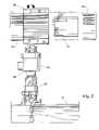
- FIG. 1is a front view of an embodiment of a non-intrusive detector made according to this invention.
- a sensor board(see FIGS. 8 to 11B ) that includes a microcontroller and at least one magnetometer sensor (“sensor”) is located in a lower portion of the sensor housing.
- the sensor housingthreads into a base structure, which is detachably secured to the pipe, until the bottom of the housing contacts the pipe surface.
- a display housinglocated at the upper end of a conduit assembly section, houses a digital display that indicates the detection of an object within the pipeline as it passes under the detector.
- a field wiring conduit boxis provided for connecting the detector to an AC/DC power source and for accommodating wiring to communicate with, for example, a control room that is controlling the opening and closing of pipeline valves.
- FIG. 2is a side view of the embodiment illustrated in FIG. 1 .
- the display housinghouses an assembly that includes a digital display insert and a DC power source (see FIGS. 6 & 7 ). As the threaded cap at the rear of the display housing is being unthreaded, the DC power source is disconnected, thereby providing a safe environment for use of the detector in explosion-proof zones.
- FIG. 3is a front view of the display panel of FIG. 1 .
- a magnetic reed switch located on the front of the panelresets a timer on the display.
- a second magnetic reed switchplaces the detector in locked or unlocked mode and allows an operator to scroll through an object detection history. When in locked mode, the device is prevented from detecting objects and the detector may be moved between locations on the pipeline without resulting in an undesired detection.
- a battery icondisplays battery life if the detector is battery-powered.
- FIG. 4is another front view of the display panel of FIG. 1 indicating that the detector is hard wired to an AC/DC power source (e.g., 24V power source) and the batteries are not in use.
- Visual indicatorsare provided to display statistics such as the number of objects that have been detected, time since detection of any object in the history, and time elapsed since reset.
- FIG. 5is an isometric view of the display insert illustrated in FIG. 2 .
- the display panel and digital displayis located at the upper end of the assembly.
- Symmetrical slotsare provided about the periphery of the insert body to retain the insert in the display housing and to ensure correct orientation of the display and provide adequate internal wiring access.
- FIG. 6is a rear isometric view of the detector illustrated in FIG. 1 with the rear cap removed from the display housing. Because the batteries engage spring-loaded contacts within the display unit, all electrical contact with the batteries is broken prior to the rear cap being completely removed. A sheet of insulating padding, preferably affixed to the underside of the rear cap, resides between the batteries and the cap to prevent electrical contact with the cap.
- FIG. 7is a partial, rear isometric view of the display housing illustrated in FIG. 1 .
- the batteriesreside in a cradle/battery holder that is received by the insert body.
- FIG. 8is a view of the sensor housing.
- the sensor housingreceives the sensor board that includes the microcontroller and the magnetometer sensor.
- FIG. 9is a view of the shielding for the sensor board of FIG. 8 .
- the inner shieldis preferably an electrically insulating material.
- the outer shieldis preferably a magnetic permeable material.
- FIG. 10is a view of the sensor board of FIG. 8 .
- the sensor boardincludes an interface for communication with the display (which could be a remote located display) or a control system, a microcontroller that runs an adaptive thresholding algorithm (see FIGS. 12 to 19 ), and a sensor.
- the sensoris preferably a magnetic flux sensor using a variable permeability material to directly measure magnetic flux.
- FIGS. 11A & 11Billustrate alternate embodiments of the sensor board of FIG. 8 .
- Two sensorsare arranged orthogonal to one another.
- the sensor boardmay use a 1-D, 2-D, 3-D or n-D array of sensors which may differ in orientation and separation of the sensor elements. Orthogonal orientations, however, are preferred.
- FIG. 12is a flowchart of a signal processing algorithm implemented by the microcontroller for processing data collected by an n-D array of sensors.
- the detection schemeis an adaptive thresholding algorithm utilizing a real-time noise estimate for the sensor or sensors.
- FIG. 13is a flowchart of the outlier removal step of the algorithm illustrated in FIG. 12 .
- FIG. 14is a flowchart of the baseline estimation step of the algorithm illustrated in FIG. 12 .
- FIG. 15is a flowchart of the noise estimation step of the algorithm illustrated in FIG. 12 .
- FIG. 16is a flowchart of the boxcar or input smoothing step of the algorithm illustrated in FIG. 12 .
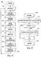
- FIG. 17is a flowchart of the detector step of the algorithm illustrated in FIG. 12 .
- FIG. 18is a flowchart of the time discriminator step of the algorithm illustrated in FIG. 12 .
- FIG. 19is a flowchart of the Bayesian lockout step of the algorithm illustrated in FIG. 12 .
- magnetometer-based detectorthat is described below is not limited in its application to the details of the construction, arrangement of the parts, and process flows illustrated in the accompanying drawings. The invention is capable of other embodiments and of being practiced or carried out in a variety of ways.
- phraseology and terminology employed hereinare for purposes of description and not limitation.
- Detector 20Sensor housing/module 21 Upper end of 20 23 Lower end of 20 25 Threaded portion of 20 30 Conduit assembly section 31 Fill plug 33 Field wiring conduit box 35 Tee fitting 37 Upper end of 30 40 Mounting base 41 Brackets 43 Shackle pin 45 Turnbuckle 47 Chain 50 Sensor board 51 Micro-controller 53 Oscillator 55 Communication interface 60 Magnetometer sensor 61 Inner insulating shield 63 Outer shield 70 Display insert/module 71 Digital display 72 Insert body 73 Object count cumulative indicator 74 Slot in 72 75 Object count history indicator 77 Object icon 79 Time since last reset indicator 81 Time since object passage in history indicator 83 Power status indicator 85 Locked/unlocked status indicator 87 Light emitting diode 89 Reed switch 90 Display housing 91 Front cap 93 Rear cap 94 Battery pack 95 Cradle/battery holder 97 Batteries 99 Insulating pad 100 Detection algorithm 110 Outlier removal algorithm 130 Baseline estimate algorithm 150 Noise estimate algorithm 170 Input smoothing algorithm 190 Detection event algorithm 210 Time discriminator algorithm
- a detector 10that is located external to a pipeline section P employs a magnetometer sensor 60 and a detection algorithm 100 to detect the presence of an object in the pipeline.
- the objectmay be in motion inside the pipeline section P with detector 10 stationary on the pipeline.
- the object in the pipelinemay be a “pig” used for pipeline maintenance or inspection.
- the objectmay carry a magnetic source or intrinsic properties of the object may allow detection.
- An example of an intrinsically marked objectwould be a “brush” pig or a pig containing a sizable amount of ferromagnetic material.
- Measurements from the magnetometer sensor 60are processed by detection algorithm 100 , which is an adaptive thresholding algorithm, to produce a “passage event.” This event may be displayed and/or counted by a digital display 70 or light emitting diode 87 . The event can also trigger outputs used to signal remote devices such as a control system for controlling the opening and closing of valves in the pipeline.
- detection algorithm 100is an adaptive thresholding algorithm, to produce a “passage event.” This event may be displayed and/or counted by a digital display 70 or light emitting diode 87 .
- the eventcan also trigger outputs used to signal remote devices such as a control system for controlling the opening and closing of valves in the pipeline.
- detector 10is detachably secured to pipeline section P by way of a mounting base 40 that receives a threaded portion 25 of sensor housing 20 .
- This arrangementprovides the capability to (1) adjust the distance between the lower end 23 of sensor housing 20 and the external wall surface of pipeline section P and (2) orient the direction of display housing 90 .
- Threaded portion 25is preferably threaded into base 40 until the lower end 23 of threaded portion 25 makes contact with the external wall surface of pipeline section P.
- Two opposing brackets 41 of base 40each receive a shackle pin 43 and an end of chain 47 .
- Chain 47along with turnbuckle 45 , is used to secure base 40 in a desired location on pipeline section P.
- the above adjustability feature of detector 10provides the ability to position magnetometer sensor 60 for maximum detection capability.
- Display housing 90Located at the upper end 37 of conduit assembly section 30 is a display housing 90 .
- Display housing 90is preferably detachably secured to conduit assembly section 30 .
- Display housing 90receives a display insert 70 that provides various indicators and statistics (see text below discussing FIGS. 3 to 5 ).
- Symmetrical slots 74 located on the periphery of the insert body 72ensure the correct orientation of the display 71 and provide necessary wiring access.
- a front cap 91 of display housing 90provides a window for the digital display 71 of display insert 70 .
- Conduit assembly section 30is located at the upper end 21 of sensor housing 20 .
- the conduit assembly section 30includes a tee fitting 35 for connecting detector 10 to a field wiring conduit box 33 .
- Conduit box 33may include wiring for placing detector 10 in communication with an AC/DC power supply, for hardwiring detector 10 to a control room, or for providing wiring to a remote display insert 70 .
- a fill plug 31may also be provided to add packing, filler, potting compound or sealant.
- display insert 70may include a digital display 71 that displays various indicators and statistics.
- digital display 71displays an object count indicator 73 , an object passage history indicator 75 , an object icon 77 , a time since last reset indicator 79 , and a time since last object in history indicator 81 .
- a microcontroller (not shown) on display 71receives information from the microcontroller 51 and magnetometer sensor 60 located on sensor board 50 (see FIG. 8 ).
- Display insert 70also includes a power source indicator 83 that indicates whether detector 10 is operating under battery power ( FIG. 3 ) or AC/DC power ( FIG. 4 ). When on battery power, power source indicator 83 preferably displays a battery icon 83 that indicates battery life.
- Digital display 71also includes a locked/unlocked status indicator 85 .
- a magnetic reed switch 89 Bplaces detector 10 in the locked or unlocked mode, thereby providing the ability to control unwanted detection. When in locked mode, detector 10 is prevented from detecting objects and may be moved between locations on the pipeline.
- Reed switch 89 Balso allows a user to interact with the statistics and scroll through the object history as indicated by indicators 75 and 81 .
- a second magnetic reed switch 89 Aresets timer 79 .
- Display unit 70also includes light-emitting diode indicators 87 to indicate whether a recent passage occurred. Light-emitting diode indicators 87 A and 87 B light up when reed switches 89 A and 89 B are triggered, respectively.
- display unit 70preferably includes a battery pack 94 .
- the cradle/battery holder 95 in which the batteries 97 residesis received by an interior space of the display insert 70 .
- Spring-loaded contacts (not shown) within display insert 70urge against the distal end of battery pack 94 so that as a user unthreads the rear cap 93 of display housing 90 , battery pack 94 is urged away from the contacts and toward the retreating rear cap 93 .
- the connection between the spring-loaded contacts and battery pack 94is, therefore, broken prior to rear cap 93 being completely removed from housing 90 .
- This featureprovides for use of detector 10 in explosion-proof zones.
- An insulating pad 99is provided between the proximal end of battery pack 94 and rear cap 93 .
- sensor housing 20houses a sensor board 50 .
- a microcontroller 51 on the sensor board 50receives data collected by magnetometer sensor 60 and runs detection algorithm 100 (see FIG. 12 ) to determine whether a passage event has occurred.
- Microcontroller 51which is of a type well known in the art, is in communication with the display unit 70 or other systems by way of a communication interface 55 .
- interface 55is a RS485 interface.
- Board 50also includes an oscillator 53 made up of a comparator, an analog switch array and an AND gate array.
- Detector 10may use a 1-D, 2-D, 3-D, or n-D array of magnetometer sensors 60 which may differ in orientation relative to one another, separation of the individual sensor elements, or both. Orthogonal orientations, as illustrated in FIGS. 11A & B, are preferred when multiple sensors 60 are used. Sensors 60 with a common orientation but that are offset may be used to improve the detection process using coincidence (or correlation) algorithms.
- sensor 60is a magnetic flux sensor using a variable permeability material. Changes in the flux alter the effective inductance of the magnetometer.
- a flux sensor manufactured by PNI Corporation, Inc.(Santa Rosa, Calif.) is an effective magnetic flux sensor 60 .
- the detection schemeis an adaptive thresholding detection process 100 based on a real-time noise estimate for the sensor(s) 60 . Parameterization allows process 100 to be adjusted for the widest application with a minimum of false alarms and a high probability of detection. Preferred range and values for critical parameters are indicated in the description of process 100 below.
- Detection process 100which is implemented by microcontroller 51 , may include all of the following processing steps: automatic elimination of outliers, computation and removal of the measurement offset, estimation of the measurement noise, establishing threshold(s) with and without hysteresis, sequential detection, and event time discrimination/detection.
- Sensor(s) 60collect magnetometer data 101 (“mag data” or mag) for processing and detection event 103 is determined by a number of criteria including but not limited to amplitude, duration, and previous events. The fine structure of the response of sensor(s) 60 may also be accounted for by using pattern recognition techniques.
- Processing step 130is a low pass filter which is used to estimate the offset from zero for the measurement.
- the low pass filteris a simple exponential type.
- the transfer function for the filteris:
- H 1 ⁇ ( z )b 0 + b 1 ⁇ z - 1 + b 2 ⁇ z - 2 a 0 + a 1 ⁇ z - 1 + a 2 ⁇ z - 2 ⁇ ⁇
- the value for time constant “f”may be in the range of 1 to 4096.
- the preferred value for “f”is 128.
- Processing step 150provides a noise estimate:
- noise imax ( noise i - 1 + ( abs ⁇ ( ( mag i - baseline ⁇ ⁇ estimate i - 1 ) - noise i - 1 ) * fn 65536 , min ⁇ ⁇ noise ) ( Eq . ⁇ 5 ) See FIG. 15 , sub-steps 151 - 163 .
- Thisis a low pass filter which produces a noise estimate for the adaptive threshold selection required by the detection process.
- the noise levelis always positive and is bounded by a minimum.
- the transfer function for the filteris:
- the input magnetometer valuesare then smoothed using a “boxcar” low pass filter in processing step 170 . See FIG. 16 , sub-steps 171 - 181 .
- the structure of the filteris:
- This filteris used to shape the response after magnitude processing (absolute value).
- the length of the rectangular windowmay be in the range of 2 to 128. In the preferred configuration the length is 32.
- the detection processoccurs in processing step 190 . See FIG. 17 , sub-steps 191 - 201 .
- processing step 210uses time to determine the extent of the event. See FIG. 18 , sub-steps 211 to 221 .
- One or more filters of the following typemay be used to characterize the event to determine if single or multiple events are present:
- processing step 230may be employed to prevent multiple passage events being detected for a single object as the object passes by detector 10 . See FIG. 19 , sub-steps 231 to 253 .
- processing step 230employs a Bayesian lockout estimator. If there is a passage event, then a detection timer is incremented and further detection is locked-out for a predetermined time period. Once the predetermined time period is exceeded, the detector is unlocked and initialized and the lockout timer is stopped and cleared until the next detection event. Similar to reed switch 89 B, processing step 230 provides the ability to control unwanted detection.
- detector 10 and process 100have been described with a certain degree of particularity, many changes may be made in the details of construction and the arrangement of components or steps without departing from the spirit and scope of this disclosure.
- the inventiontherefore, is not limited to the embodiments set forth herein for purposes of exemplification, but is to be limited only by the scope of the attached claims, including the full range of equivalency to which each element thereof is entitled.
Landscapes
- Engineering & Computer Science (AREA)
- General Engineering & Computer Science (AREA)
- Chemical & Material Sciences (AREA)
- Physics & Mathematics (AREA)
- Life Sciences & Earth Sciences (AREA)
- General Physics & Mathematics (AREA)
- Combustion & Propulsion (AREA)
- Mechanical Engineering (AREA)
- Remote Sensing (AREA)
- Electromagnetism (AREA)
- Health & Medical Sciences (AREA)
- General Life Sciences & Earth Sciences (AREA)
- Environmental & Geological Engineering (AREA)
- Geophysics (AREA)
- Chemical Kinetics & Catalysis (AREA)
- Electrochemistry (AREA)
- Geology (AREA)
- Analytical Chemistry (AREA)
- Biochemistry (AREA)
- General Health & Medical Sciences (AREA)
- Immunology (AREA)
- Pathology (AREA)
- Geophysics And Detection Of Objects (AREA)
- Investigating Or Analyzing Materials By The Use Of Magnetic Means (AREA)
- Measuring Magnetic Variables (AREA)
Abstract
Description
| 10 | |
| 20 | Sensor housing/ |
| 21 | Upper end of 20 |
| 23 | Lower end of 20 |
| 25 | Threaded portion of 20 |
| 30 | |
| 31 | |
| 33 | Field |
| 35 | Tee fitting |
| 37 | Upper end of 30 |
| 40 | |
| 41 | |
| 43 | |
| 45 | |
| 47 | |
| 50 | |
| 51 | Micro-controller |
| 53 | |
| 55 | |
| 60 | |
| 61 | Inner insulating |
| 63 | |
| 70 | Display insert/ |
| 71 | |
| 72 | |
| 73 | Object count |
| 74 | Slot in 72 |
| 75 | Object |
| 77 | |
| 79 | Time since |
| 81 | Time since object passage in |
| 83 | |
| 85 | Locked/unlocked status indicator |
| 87 | Light emitting diode |
| 89 | |
| 90 | |
| 91 | |
| 93 | |
| 94 | |
| 95 | Cradle/ |
| 97 | |
| 99 | |
| 100 | |
| 110 | |
| 130 | |
| 150 | |
| 170 | |
| 190 | |
| 210 | |
| 230 | Lockout discriminator algorithm |
magi=min(magi−baseline estimatei-1*signum(magi), outlier limit) (Eq. 1)
See
baseline estimatei=baseline estimatei-1+(magi−baseline estimatei-1)*f/65536 (Eq. 2)
See
The value for time constant “f” may be in the range of 1 to 4096. The preferred value for “f” is 128. The baseline estimate is:
baseline estimate=H1(z)*mag (Eq. 4)
See
The value for time constant “fn” may be in the range of 1 to 256. The preferred value for “fn” is 32. The noise estimate is:
noise=H2(z)*(abs(mag−baseline)) (Eq. 7)
This filter is used to shape the response after magnitude processing (absolute value). The length of the rectangular window may be in the range of 2 to 128. In the preferred configuration the length is 32.
if (H3(z)*(abs(magi)−baseline estimatei)≧upper thresholdi) and (detectori-1=0) then detectori=1 (Eq. 9a)
If (H3(z)*(abs(magi)−baseline estimatei)≦lower thresholdi) and (detectori-1=1) then detectori=0 (Eq. 9b)
else detectori=detectori-1 (Eq. 9c)
The determination of the upper and lower detection thresholds is:
upper thresholdi=p1*noisei (Eq. 10a)
lower thresholdi=p2*noisei (Eq. 10b)
The value for p1 and p2 may be in the range of 1 to 10. The preferred value for p1 is 3. The preferred value for p2 is 1.
This transfer function operates on the detected output, whose value is 0 or 1. Various lengths of rectangular windows can be used to discriminate between short and long events. The longest window, passing the detection limit, indicates the extent of a single event:
event detect=H4(z)*detect (Eq. 12).
Claims (32)
Priority Applications (12)
| Application Number | Priority Date | Filing Date | Title |
|---|---|---|---|
| US12/470,654US8378667B2 (en) | 2009-05-22 | 2009-05-22 | System and method for detecting the passage of an object in pipeline including shielded magnetometer and a microcontroller with adaptive thresholding detection means |
| BRPI1008252ABRPI1008252A2 (en) | 2009-05-22 | 2010-05-19 | system and method for detecting the passage of an object in a pipe |
| SG2011081395ASG175898A1 (en) | 2009-05-22 | 2010-05-19 | Magnetometer-based detector for objects in a pipeline |
| JP2012511983AJP2012527623A (en) | 2009-05-22 | 2010-05-19 | Magnetometer-based detector for objects in pipelines |
| MX2011012404AMX2011012404A (en) | 2009-05-22 | 2010-05-19 | Magnetometer-based detector for objects in a pipeline. |
| CA2762102ACA2762102A1 (en) | 2009-05-22 | 2010-05-19 | Magnetometer-based detector for objects in a pipeline |
| KR1020117027768AKR20120020127A (en) | 2009-05-22 | 2010-05-19 | Magnetometer-based detector for objects in a pipeline |
| RU2011152230/28ARU2011152230A (en) | 2009-05-22 | 2010-05-19 | DETECTOR FOR DETECTING OBJECTS IN A PIPELINE BASED ON A MAGNETOMETRIC SENSOR |
| CN2010800225128ACN102439434A (en) | 2009-05-22 | 2010-05-19 | Magnetometer-based detector for objects in a pipeline |
| PCT/US2010/035361WO2010135400A1 (en) | 2009-05-22 | 2010-05-19 | Magnetometer-based detector for objects in a pipeline |
| EP10778308.6AEP2433118A4 (en) | 2009-05-22 | 2010-05-19 | Magnetometer-based detector for objects in a pipeline |
| AU2010249619AAU2010249619B2 (en) | 2009-05-22 | 2010-05-19 | Magnetometer-based detector for objects in a pipeline |
Applications Claiming Priority (1)
| Application Number | Priority Date | Filing Date | Title |
|---|---|---|---|
| US12/470,654US8378667B2 (en) | 2009-05-22 | 2009-05-22 | System and method for detecting the passage of an object in pipeline including shielded magnetometer and a microcontroller with adaptive thresholding detection means |
Publications (2)
| Publication Number | Publication Date |
|---|---|
| US20100295543A1 US20100295543A1 (en) | 2010-11-25 |
| US8378667B2true US8378667B2 (en) | 2013-02-19 |
Family
ID=43124169
Family Applications (1)
| Application Number | Title | Priority Date | Filing Date |
|---|---|---|---|
| US12/470,654Expired - Fee RelatedUS8378667B2 (en) | 2009-05-22 | 2009-05-22 | System and method for detecting the passage of an object in pipeline including shielded magnetometer and a microcontroller with adaptive thresholding detection means |
Country Status (12)
| Country | Link |
|---|---|
| US (1) | US8378667B2 (en) |
| EP (1) | EP2433118A4 (en) |
| JP (1) | JP2012527623A (en) |
| KR (1) | KR20120020127A (en) |
| CN (1) | CN102439434A (en) |
| AU (1) | AU2010249619B2 (en) |
| BR (1) | BRPI1008252A2 (en) |
| CA (1) | CA2762102A1 (en) |
| MX (1) | MX2011012404A (en) |
| RU (1) | RU2011152230A (en) |
| SG (1) | SG175898A1 (en) |
| WO (1) | WO2010135400A1 (en) |
Cited By (3)
| Publication number | Priority date | Publication date | Assignee | Title |
|---|---|---|---|---|
| US9172406B2 (en) | 2013-05-03 | 2015-10-27 | Control Devices, Inc. | Pressure resistant housing device for protecting an electromagnetic transmitter |
| US20150316196A1 (en)* | 2014-04-30 | 2015-11-05 | Control Devices, Inc. | Acoustic transmitter and method for underwater pipeline inspection gauges |
| US9310338B2 (en)* | 2010-10-14 | 2016-04-12 | Halliburton Energy Services, Inc. | Method for measuring remote field eddy current thickness in multiple tubular configuration |
Families Citing this family (4)
| Publication number | Priority date | Publication date | Assignee | Title |
|---|---|---|---|---|
| EP2789990B1 (en)* | 2013-04-10 | 2016-03-16 | Enrichment Technology Company Ltd. Zweigniederlassung Deutschland | Mobile detection apparatus for magnetic plugs in pipework systems |
| US20150344328A1 (en)* | 2014-05-30 | 2015-12-03 | Vladimir SUVOROV | Method and device for water treatment using radio waves |
| ES2938192T3 (en) | 2017-10-10 | 2023-04-05 | Alert Systems Aps | Theft prevention system and method with magnetic field detection |
| KR102200861B1 (en)* | 2019-07-16 | 2021-01-11 | 주식회사 부산도시가스 | Emergency repair apparatus for gas supplying pipe road and emergency repair method for gas supplying pipe road |
Citations (36)
| Publication number | Priority date | Publication date | Assignee | Title |
|---|---|---|---|---|
| US3443211A (en)* | 1965-04-01 | 1969-05-06 | American Mach & Foundry | Magnetometer inspection apparatus for ferromagnetic objects |
| US3673629A (en) | 1969-06-16 | 1972-07-04 | Lloyd Ltd Ernest | Magnetic pipeline pigs |
| US3878453A (en) | 1973-09-21 | 1975-04-15 | Trans Canada Pipelines Ltd | Pipeline signalling systems and techniques |
| US3888260A (en) | 1972-06-28 | 1975-06-10 | Univ Johns Hopkins | Rechargeable demand inhibited cardiac pacer and tissue stimulator |
| US3975772A (en)* | 1975-06-02 | 1976-08-17 | International Business Machines Corporation | Double shielded magnetorestive sensing element |
| US4091322A (en) | 1976-05-24 | 1978-05-23 | Societe Intersub Developpement | Eddy current generating type metal pipeline detector |
| US4134061A (en) | 1977-02-02 | 1979-01-09 | Gudgel Howard S | Pipe current detector with plural magnetic flux detectors |
| US4427943A (en) | 1981-08-05 | 1984-01-24 | Innovatum, Inc. | Apparatus and method for locating and tracking magnetic objects or sources |
| US4430613A (en) | 1980-07-28 | 1984-02-07 | French Hartley A | Pipeline inspection and maintenance method including moving a magnetic field responsive device along the route of the pipeline |
| US4439730A (en) | 1981-05-08 | 1984-03-27 | Amf Inc. | Nondestructive inspection apparatus and method utilizing combined inspection signals obtained from orthogonal magnetic fields |
| US4491018A (en) | 1983-06-17 | 1985-01-01 | F. H. Maloney Company | Pig detector |
| US4714888A (en) | 1984-06-11 | 1987-12-22 | French Hartley A | Apparatus for observing the passage of a pig in a pipeline |
| US4857851A (en) | 1981-09-23 | 1989-08-15 | British Gas Corporation | Fixing a geographical reference of a vehicle traveling through a pipeline |
| US5030911A (en)* | 1980-10-19 | 1991-07-09 | Baker Hughes Incorporated | Method and apparatus for displaying defects in tubular members on a two-dimensional map in a variety of display modes |
| US5065098A (en) | 1990-06-18 | 1991-11-12 | The Charles Machine Works, Inc. | System for locating concealed underground objects using digital filtering |
| US5122744A (en) | 1990-10-09 | 1992-06-16 | Ibm Corporation | Gradiometer having a magnetometer which cancels background magnetic field from other magnetometers |
| US5126654A (en) | 1989-02-10 | 1992-06-30 | New York Gas Group | Non-invasive, high resolution detection of electrical currents and electrochemical impedances at spaced localities along a pipeline |
| US5417112A (en) | 1993-01-11 | 1995-05-23 | Tdw Delaware, Inc. | Apparatus for indicating the passage of a pig moving within an underground pipeline |
| US5461312A (en)* | 1991-04-22 | 1995-10-24 | Tokyo Gas Co., Ltd. | Remote field eddy current sensor for detecting flaws in metal material |
| US5506505A (en) | 1994-05-09 | 1996-04-09 | Tdw Delaware, Inc. | Apparatus for remotely indicating pipeline pig including a sensor housing having surface engaging orthogonally disposed paramagnetic materials a solid state sensor and a flag |
| US5651638A (en) | 1995-09-01 | 1997-07-29 | Crc-Evans Pipeline International, Inc. | Method and apparatus for controlling the position and operation of equipment within a pipeline |
| WO1999032902A2 (en) | 1997-12-23 | 1999-07-01 | Pii North America, Inc. | Method and apparatus for determining location of characteristics of a pipeline |
| US5963042A (en) | 1994-12-16 | 1999-10-05 | Tokyo Gas Co., Ltd. | Method for inspecting the elements of piping systems by electromagnetic waves |
| US6087830A (en) | 1994-07-07 | 2000-07-11 | Hydroscope Canada Inc. | Flexible device for remote field eddy current inspection of ferrous pipeline containing turns |
| US6097189A (en) | 1997-09-29 | 2000-08-01 | The United States Of America As Represented By The Administrator Of The National Aeronautics And Space Administration | Object locating system |
| US6339328B1 (en) | 1997-03-10 | 2002-01-15 | The Secretary Of State For Defence | Magnetic gradiometer incorporating global feedback |
| US6404189B2 (en) | 1999-03-17 | 2002-06-11 | Southeast Research Institute | Method and apparatus for inspecting pipelines from an in-line inspection vehicle using magnetostrictive probes |
| US6489771B1 (en) | 2000-07-20 | 2002-12-03 | Farque Claude A. | Passive external noise-canceling dynamic magnetic flux sensor for detecting the presence and direction of movement of a pig in a pipe |
| US20030055321A1 (en) | 2001-07-16 | 2003-03-20 | Watrous Raymond L. | System and method for accessing and processing patient data |
| US20030117134A1 (en)* | 2001-12-20 | 2003-06-26 | Schlumberger Technology Corporation | Downhole magnetic-field based feature detector |
| EP1397541A1 (en) | 2001-05-10 | 2004-03-17 | Neumag GmbH & Co. KG | Compressive crimping device for a synthetic multi-threaded yarn |
| US20040227509A1 (en)* | 2003-02-28 | 2004-11-18 | Eisenmann Lacktechnik Kg | Position detector for a moving part in a pipe |
| US6965320B1 (en) | 2001-10-31 | 2005-11-15 | Star Trak Pigging Technologies, Inc. | Cathodic test lead and pig monitoring system |
| US20060076951A1 (en) | 2004-10-07 | 2006-04-13 | Battelle Memorial Institute | Pipeline inspection apparatus and method |
| WO2008046209A1 (en) | 2006-10-17 | 2008-04-24 | Athena Industrial Technologies Inc. | Inspection apparatus and method |
| US7402999B2 (en) | 2005-11-30 | 2008-07-22 | General Electric Company | Pulsed eddy current pipeline inspection system and method |
Family Cites Families (10)
| Publication number | Priority date | Publication date | Assignee | Title |
|---|---|---|---|---|
| JPS5636049A (en)* | 1979-08-31 | 1981-04-09 | Sanko Denshi Kenkyusho:Kk | Method and device for detecting magnetic substance |
| JPS5945855U (en)* | 1982-09-18 | 1984-03-27 | 富士電機株式会社 | Battery storage mechanism for flameproof and explosion-proof electrical equipment |
| GB8510732D0 (en)* | 1985-04-26 | 1985-06-05 | Univ Edinburgh | Oil debris monitor |
| JP3046888B2 (en)* | 1993-03-10 | 2000-05-29 | 三菱重工業株式会社 | Significant signal section extraction device |
| JP2833497B2 (en)* | 1994-12-07 | 1998-12-09 | 財団法人雑賀技術研究所 | Moving conductor detecting coil and moving conductor detecting device using the same |
| JPH1114599A (en)* | 1997-06-24 | 1999-01-22 | Toyota Motor Corp | Flaw detection device by magnetic flux leakage detection method |
| GB9816083D0 (en)* | 1998-07-24 | 1998-09-23 | Jme Ltd | Pipeline crawler control and/or tracking system |
| JP4395559B2 (en)* | 2004-09-28 | 2010-01-13 | アイチ・マイクロ・インテリジェント株式会社 | Metal detector |
| CN200947118Y (en)* | 2006-01-10 | 2007-09-12 | 沈阳永业实业有限公司 | Magnetic explosion-proof passing indicator |
| DE102007004104A1 (en)* | 2007-01-26 | 2008-07-31 | Ksb Aktiengesellschaft | Position detector for a part moved in a pipe |
- 2009
- 2009-05-22USUS12/470,654patent/US8378667B2/ennot_activeExpired - Fee Related
- 2010
- 2010-05-19WOPCT/US2010/035361patent/WO2010135400A1/enactiveApplication Filing
- 2010-05-19BRBRPI1008252Apatent/BRPI1008252A2/ennot_activeIP Right Cessation
- 2010-05-19CNCN2010800225128Apatent/CN102439434A/enactivePending
- 2010-05-19KRKR1020117027768Apatent/KR20120020127A/ennot_activeWithdrawn
- 2010-05-19JPJP2012511983Apatent/JP2012527623A/ennot_activeCeased
- 2010-05-19MXMX2011012404Apatent/MX2011012404A/enactiveIP Right Grant
- 2010-05-19CACA2762102Apatent/CA2762102A1/ennot_activeAbandoned
- 2010-05-19SGSG2011081395Apatent/SG175898A1/enunknown
- 2010-05-19EPEP10778308.6Apatent/EP2433118A4/ennot_activeWithdrawn
- 2010-05-19AUAU2010249619Apatent/AU2010249619B2/ennot_activeExpired - Fee Related
- 2010-05-19RURU2011152230/28Apatent/RU2011152230A/ennot_activeApplication Discontinuation
Patent Citations (37)
| Publication number | Priority date | Publication date | Assignee | Title |
|---|---|---|---|---|
| US3443211A (en)* | 1965-04-01 | 1969-05-06 | American Mach & Foundry | Magnetometer inspection apparatus for ferromagnetic objects |
| US3673629A (en) | 1969-06-16 | 1972-07-04 | Lloyd Ltd Ernest | Magnetic pipeline pigs |
| US3888260A (en) | 1972-06-28 | 1975-06-10 | Univ Johns Hopkins | Rechargeable demand inhibited cardiac pacer and tissue stimulator |
| US3878453A (en) | 1973-09-21 | 1975-04-15 | Trans Canada Pipelines Ltd | Pipeline signalling systems and techniques |
| US3975772A (en)* | 1975-06-02 | 1976-08-17 | International Business Machines Corporation | Double shielded magnetorestive sensing element |
| US4091322A (en) | 1976-05-24 | 1978-05-23 | Societe Intersub Developpement | Eddy current generating type metal pipeline detector |
| US4134061A (en) | 1977-02-02 | 1979-01-09 | Gudgel Howard S | Pipe current detector with plural magnetic flux detectors |
| US4430613A (en) | 1980-07-28 | 1984-02-07 | French Hartley A | Pipeline inspection and maintenance method including moving a magnetic field responsive device along the route of the pipeline |
| US5030911A (en)* | 1980-10-19 | 1991-07-09 | Baker Hughes Incorporated | Method and apparatus for displaying defects in tubular members on a two-dimensional map in a variety of display modes |
| US4439730A (en) | 1981-05-08 | 1984-03-27 | Amf Inc. | Nondestructive inspection apparatus and method utilizing combined inspection signals obtained from orthogonal magnetic fields |
| US4427943A (en) | 1981-08-05 | 1984-01-24 | Innovatum, Inc. | Apparatus and method for locating and tracking magnetic objects or sources |
| US4857851A (en) | 1981-09-23 | 1989-08-15 | British Gas Corporation | Fixing a geographical reference of a vehicle traveling through a pipeline |
| US4491018A (en) | 1983-06-17 | 1985-01-01 | F. H. Maloney Company | Pig detector |
| US4714888A (en) | 1984-06-11 | 1987-12-22 | French Hartley A | Apparatus for observing the passage of a pig in a pipeline |
| US5126654A (en) | 1989-02-10 | 1992-06-30 | New York Gas Group | Non-invasive, high resolution detection of electrical currents and electrochemical impedances at spaced localities along a pipeline |
| US5065098A (en) | 1990-06-18 | 1991-11-12 | The Charles Machine Works, Inc. | System for locating concealed underground objects using digital filtering |
| US5122744A (en) | 1990-10-09 | 1992-06-16 | Ibm Corporation | Gradiometer having a magnetometer which cancels background magnetic field from other magnetometers |
| US5461312A (en)* | 1991-04-22 | 1995-10-24 | Tokyo Gas Co., Ltd. | Remote field eddy current sensor for detecting flaws in metal material |
| US5417112A (en) | 1993-01-11 | 1995-05-23 | Tdw Delaware, Inc. | Apparatus for indicating the passage of a pig moving within an underground pipeline |
| US5506505A (en) | 1994-05-09 | 1996-04-09 | Tdw Delaware, Inc. | Apparatus for remotely indicating pipeline pig including a sensor housing having surface engaging orthogonally disposed paramagnetic materials a solid state sensor and a flag |
| US6087830A (en) | 1994-07-07 | 2000-07-11 | Hydroscope Canada Inc. | Flexible device for remote field eddy current inspection of ferrous pipeline containing turns |
| US5963042A (en) | 1994-12-16 | 1999-10-05 | Tokyo Gas Co., Ltd. | Method for inspecting the elements of piping systems by electromagnetic waves |
| US5651638A (en) | 1995-09-01 | 1997-07-29 | Crc-Evans Pipeline International, Inc. | Method and apparatus for controlling the position and operation of equipment within a pipeline |
| US6339328B1 (en) | 1997-03-10 | 2002-01-15 | The Secretary Of State For Defence | Magnetic gradiometer incorporating global feedback |
| US6097189A (en) | 1997-09-29 | 2000-08-01 | The United States Of America As Represented By The Administrator Of The National Aeronautics And Space Administration | Object locating system |
| US6243657B1 (en) | 1997-12-23 | 2001-06-05 | Pii North America, Inc. | Method and apparatus for determining location of characteristics of a pipeline |
| WO1999032902A2 (en) | 1997-12-23 | 1999-07-01 | Pii North America, Inc. | Method and apparatus for determining location of characteristics of a pipeline |
| US6404189B2 (en) | 1999-03-17 | 2002-06-11 | Southeast Research Institute | Method and apparatus for inspecting pipelines from an in-line inspection vehicle using magnetostrictive probes |
| US6489771B1 (en) | 2000-07-20 | 2002-12-03 | Farque Claude A. | Passive external noise-canceling dynamic magnetic flux sensor for detecting the presence and direction of movement of a pig in a pipe |
| EP1397541A1 (en) | 2001-05-10 | 2004-03-17 | Neumag GmbH & Co. KG | Compressive crimping device for a synthetic multi-threaded yarn |
| US20030055321A1 (en) | 2001-07-16 | 2003-03-20 | Watrous Raymond L. | System and method for accessing and processing patient data |
| US6965320B1 (en) | 2001-10-31 | 2005-11-15 | Star Trak Pigging Technologies, Inc. | Cathodic test lead and pig monitoring system |
| US20030117134A1 (en)* | 2001-12-20 | 2003-06-26 | Schlumberger Technology Corporation | Downhole magnetic-field based feature detector |
| US20040227509A1 (en)* | 2003-02-28 | 2004-11-18 | Eisenmann Lacktechnik Kg | Position detector for a moving part in a pipe |
| US20060076951A1 (en) | 2004-10-07 | 2006-04-13 | Battelle Memorial Institute | Pipeline inspection apparatus and method |
| US7402999B2 (en) | 2005-11-30 | 2008-07-22 | General Electric Company | Pulsed eddy current pipeline inspection system and method |
| WO2008046209A1 (en) | 2006-10-17 | 2008-04-24 | Athena Industrial Technologies Inc. | Inspection apparatus and method |
Non-Patent Citations (3)
| Title |
|---|
| International Search Report and Written Opinion issued by the International Searching Authority (ISA/US) on Jun. 1, 2010 in PCT/US2010/029967 (10 pgs). |
| Karki. Active Low-Pass Filter Design, Appln Report SLOA049A-Oct. 2000. http://www.science.unitn.it~bassi/Signal/Tlnotes/sloa049.pdf> (24 pgs). |
| Karki. Active Low-Pass Filter Design, Appln Report SLOA049A—Oct. 2000. http://www.science.unitn.it˜bassi/Signal/Tlnotes/sloa049.pdf> (24 pgs). |
Cited By (4)
| Publication number | Priority date | Publication date | Assignee | Title |
|---|---|---|---|---|
| US9310338B2 (en)* | 2010-10-14 | 2016-04-12 | Halliburton Energy Services, Inc. | Method for measuring remote field eddy current thickness in multiple tubular configuration |
| US9172406B2 (en) | 2013-05-03 | 2015-10-27 | Control Devices, Inc. | Pressure resistant housing device for protecting an electromagnetic transmitter |
| US20150316196A1 (en)* | 2014-04-30 | 2015-11-05 | Control Devices, Inc. | Acoustic transmitter and method for underwater pipeline inspection gauges |
| US9535039B2 (en)* | 2014-04-30 | 2017-01-03 | Control Devices, Inc. | Acoustic transmitter and method for underwater pipeline inspection gauges |
Also Published As
| Publication number | Publication date |
|---|---|
| EP2433118A4 (en) | 2014-03-12 |
| AU2010249619B2 (en) | 2015-02-12 |
| EP2433118A1 (en) | 2012-03-28 |
| RU2011152230A (en) | 2013-06-27 |
| BRPI1008252A2 (en) | 2016-05-31 |
| JP2012527623A (en) | 2012-11-08 |
| SG175898A1 (en) | 2011-12-29 |
| CA2762102A1 (en) | 2010-11-25 |
| WO2010135400A1 (en) | 2010-11-25 |
| AU2010249619A1 (en) | 2011-11-17 |
| KR20120020127A (en) | 2012-03-07 |
| US20100295543A1 (en) | 2010-11-25 |
| MX2011012404A (en) | 2012-03-06 |
| CN102439434A (en) | 2012-05-02 |
Similar Documents
| Publication | Publication Date | Title |
|---|---|---|
| US8378667B2 (en) | System and method for detecting the passage of an object in pipeline including shielded magnetometer and a microcontroller with adaptive thresholding detection means | |
| US7113092B2 (en) | Ferromagnetic object detector | |
| JP6426101B2 (en) | Device for detecting ferromagnets in a protected access port assembly | |
| US6724316B2 (en) | Method and apparatus for detection of motion with a gravitational field detector in a security system | |
| CA2443773C (en) | Remote fire extinguisher station inspection | |
| ES2938192T3 (en) | Theft prevention system and method with magnetic field detection | |
| EP2997557B1 (en) | Theft-preventing system and method with magnetic field detection | |
| CN207776611U (en) | Door lock | |
| CA2481803A1 (en) | Detection of ferromagnetic objects approaching a magnet | |
| WO2008105975A4 (en) | Method and apparatus for rejecting radioactive interference in a radiation monitoring station | |
| CA2794811A1 (en) | Dynamic self-checking interlock monitoring system | |
| EP4005678B1 (en) | Measuring magnetite buildup in a magnetic filter | |
| EP4189196A1 (en) | Magnetic door position detection apparatus | |
| WO2003065055A3 (en) | Magnetic field detection system for an electricity meter | |
| CN104080987B (en) | Pond monitoring system and related monitoring method | |
| CN105301528B (en) | Method and apparatus for monitoring device including Hall effect sensor, electricity meter | |
| CN110503813A (en) | A monitoring and early warning method for buried pipeline anti-excavation |
Legal Events
| Date | Code | Title | Description |
|---|---|---|---|
| AS | Assignment | Owner name:TDW DELAWARE, INC., DELAWARE Free format text:ASSIGNMENT OF ASSIGNORS INTEREST;ASSIGNORS:MISKA, STEPHEN J.;RANKIN, WILLIAM J.;LOGAN, MATTHEW W.;AND OTHERS;SIGNING DATES FROM 20090520 TO 20090521;REEL/FRAME:022728/0242 | |
| STCF | Information on status: patent grant | Free format text:PATENTED CASE | |
| AS | Assignment | Owner name:JPMORGAN CHASE BANK, N.A., OKLAHOMA Free format text:SECURITY AGREEMENT;ASSIGNOR:TDW DELAWARE, INC.;REEL/FRAME:038890/0574 Effective date:20160526 | |
| FPAY | Fee payment | Year of fee payment:4 | |
| AS | Assignment | Owner name:JPMORGAN CHASE BANK, N.A., AS ADMINISTRATIVE ASSISTANT, ILLINOIS Free format text:SECURITY INTEREST;ASSIGNOR:TDW DELAWARE, INC.;REEL/FRAME:052900/0932 Effective date:20200610 | |
| MAFP | Maintenance fee payment | Free format text:PAYMENT OF MAINTENANCE FEE, 8TH YEAR, LARGE ENTITY (ORIGINAL EVENT CODE: M1552); ENTITY STATUS OF PATENT OWNER: LARGE ENTITY Year of fee payment:8 | |
| AS | Assignment | Owner name:TDW DELAWARE, INC., OKLAHOMA Free format text:RELEASE BY SECURED PARTY;ASSIGNOR:JPMORGAN CHASE BANK, N.A.;REEL/FRAME:061002/0552 Effective date:20220630 Owner name:TDW DELAWARE, INC., OKLAHOMA Free format text:RELEASE BY SECURED PARTY;ASSIGNOR:JPMORGAN CHASE BANK, N.A.;REEL/FRAME:060655/0561 Effective date:20220630 | |
| AS | Assignment | Owner name:CADENCE BANK, TEXAS Free format text:SECURITY INTEREST;ASSIGNOR:TDW DELAWARE, INC.;REEL/FRAME:061147/0932 Effective date:20220630 | |
| FEPP | Fee payment procedure | Free format text:MAINTENANCE FEE REMINDER MAILED (ORIGINAL EVENT CODE: REM.); ENTITY STATUS OF PATENT OWNER: LARGE ENTITY | |
| LAPS | Lapse for failure to pay maintenance fees | Free format text:PATENT EXPIRED FOR FAILURE TO PAY MAINTENANCE FEES (ORIGINAL EVENT CODE: EXP.); ENTITY STATUS OF PATENT OWNER: LARGE ENTITY | |
| STCH | Information on status: patent discontinuation | Free format text:PATENT EXPIRED DUE TO NONPAYMENT OF MAINTENANCE FEES UNDER 37 CFR 1.362 | |
| FP | Lapsed due to failure to pay maintenance fee | Effective date:20250219 |