US8378623B2 - Apparatus and method for charging an electric vehicle - Google Patents
Apparatus and method for charging an electric vehicleDownload PDFInfo
- Publication number
- US8378623B2 US8378623B2US12/940,085US94008510AUS8378623B2US 8378623 B2US8378623 B2US 8378623B2US 94008510 AUS94008510 AUS 94008510AUS 8378623 B2US8378623 B2US 8378623B2
- Authority
- US
- United States
- Prior art keywords
- energy
- electrical
- port
- esms
- ports
- Prior art date
- Legal status (The legal status is an assumption and is not a legal conclusion. Google has not performed a legal analysis and makes no representation as to the accuracy of the status listed.)
- Active, expires
Links
- 238000000034methodMethods0.000titleclaimsdescription7
- 238000004146energy storageMethods0.000claimsabstractdescription91
- 238000006243chemical reactionMethods0.000claimsabstractdescription12
- 238000002485combustion reactionMethods0.000claimsdescription16
- 230000005540biological transmissionEffects0.000claimsdescription11
- 230000008878couplingEffects0.000claimsdescription7
- 238000010168coupling processMethods0.000claimsdescription7
- 238000005859coupling reactionMethods0.000claimsdescription7
- 238000004590computer programMethods0.000claimsdescription3
- 238000004519manufacturing processMethods0.000claimsdescription3
- 238000005259measurementMethods0.000claims4
- 238000002330electrospray ionisation mass spectrometryMethods0.000abstract1
- 238000007726management methodMethods0.000description18
- 239000003990capacitorSubstances0.000description8
- 230000010354integrationEffects0.000description6
- 230000001133accelerationEffects0.000description5
- 241000156302Porcine hemagglutinating encephalomyelitis virusSpecies0.000description4
- 238000010586diagramMethods0.000description4
- 239000007789gasSubstances0.000description4
- 238000012546transferMethods0.000description4
- 230000008901benefitEffects0.000description3
- 239000000446fuelSubstances0.000description3
- 238000012937correctionMethods0.000description2
- 238000013461designMethods0.000description2
- 230000009977dual effectEffects0.000description2
- 230000013011matingEffects0.000description2
- 230000001172regenerating effectEffects0.000description2
- 230000001105regulatory effectEffects0.000description2
- WHXSMMKQMYFTQS-UHFFFAOYSA-NLithiumChemical compound[Li]WHXSMMKQMYFTQS-UHFFFAOYSA-N0.000description1
- HBBGRARXTFLTSG-UHFFFAOYSA-NLithium ionChemical compound[Li+]HBBGRARXTFLTSG-UHFFFAOYSA-N0.000description1
- KEAYESYHFKHZAL-UHFFFAOYSA-NSodiumChemical compound[Na]KEAYESYHFKHZAL-UHFFFAOYSA-N0.000description1
- TWLBWHPWXLPSNU-UHFFFAOYSA-L[Na].[Cl-].[Cl-].[Ni++]Chemical compound[Na].[Cl-].[Cl-].[Ni++]TWLBWHPWXLPSNU-UHFFFAOYSA-L0.000description1
- BNOODXBBXFZASF-UHFFFAOYSA-N[Na].[S]Chemical compound[Na].[S]BNOODXBBXFZASF-UHFFFAOYSA-N0.000description1
- 230000001154acute effectEffects0.000description1
- 230000004075alterationEffects0.000description1
- 238000013459approachMethods0.000description1
- QVGXLLKOCUKJST-UHFFFAOYSA-Natomic oxygenChemical compound[O]QVGXLLKOCUKJST-UHFFFAOYSA-N0.000description1
- OJIJEKBXJYRIBZ-UHFFFAOYSA-Ncadmium nickelChemical compound[Ni].[Cd]OJIJEKBXJYRIBZ-UHFFFAOYSA-N0.000description1
- 238000004891communicationMethods0.000description1
- 230000001010compromised effectEffects0.000description1
- 230000001419dependent effectEffects0.000description1
- 238000011161developmentMethods0.000description1
- 230000000694effectsEffects0.000description1
- 238000005516engineering processMethods0.000description1
- 238000007667floatingMethods0.000description1
- 230000006872improvementEffects0.000description1
- 238000002955isolationMethods0.000description1
- 229910052744lithiumInorganic materials0.000description1
- 229910001416lithium ionInorganic materials0.000description1
- 229910001507metal halideInorganic materials0.000description1
- 229910052987metal hydrideInorganic materials0.000description1
- 229910052759nickelInorganic materials0.000description1
- PXHVJJICTQNCMI-UHFFFAOYSA-NnickelSubstances[Ni]PXHVJJICTQNCMI-UHFFFAOYSA-N0.000description1
- -1nickel metal hydrideChemical class0.000description1
- 229910052760oxygenInorganic materials0.000description1
- 239000001301oxygenSubstances0.000description1
- 229920000642polymerPolymers0.000description1
- 238000011084recoveryMethods0.000description1
- 238000007493shaping processMethods0.000description1
- 238000006467substitution reactionMethods0.000description1
- 230000002459sustained effectEffects0.000description1
Images


Classifications
- B—PERFORMING OPERATIONS; TRANSPORTING
- B60—VEHICLES IN GENERAL
- B60L—PROPULSION OF ELECTRICALLY-PROPELLED VEHICLES; SUPPLYING ELECTRIC POWER FOR AUXILIARY EQUIPMENT OF ELECTRICALLY-PROPELLED VEHICLES; ELECTRODYNAMIC BRAKE SYSTEMS FOR VEHICLES IN GENERAL; MAGNETIC SUSPENSION OR LEVITATION FOR VEHICLES; MONITORING OPERATING VARIABLES OF ELECTRICALLY-PROPELLED VEHICLES; ELECTRIC SAFETY DEVICES FOR ELECTRICALLY-PROPELLED VEHICLES
- B60L50/00—Electric propulsion with power supplied within the vehicle
- B60L50/10—Electric propulsion with power supplied within the vehicle using propulsion power supplied by engine-driven generators, e.g. generators driven by combustion engines
- B60L50/16—Electric propulsion with power supplied within the vehicle using propulsion power supplied by engine-driven generators, e.g. generators driven by combustion engines with provision for separate direct mechanical propulsion
- B—PERFORMING OPERATIONS; TRANSPORTING
- B60—VEHICLES IN GENERAL
- B60L—PROPULSION OF ELECTRICALLY-PROPELLED VEHICLES; SUPPLYING ELECTRIC POWER FOR AUXILIARY EQUIPMENT OF ELECTRICALLY-PROPELLED VEHICLES; ELECTRODYNAMIC BRAKE SYSTEMS FOR VEHICLES IN GENERAL; MAGNETIC SUSPENSION OR LEVITATION FOR VEHICLES; MONITORING OPERATING VARIABLES OF ELECTRICALLY-PROPELLED VEHICLES; ELECTRIC SAFETY DEVICES FOR ELECTRICALLY-PROPELLED VEHICLES
- B60L50/00—Electric propulsion with power supplied within the vehicle
- B60L50/40—Electric propulsion with power supplied within the vehicle using propulsion power supplied by capacitors
- B—PERFORMING OPERATIONS; TRANSPORTING
- B60—VEHICLES IN GENERAL
- B60L—PROPULSION OF ELECTRICALLY-PROPELLED VEHICLES; SUPPLYING ELECTRIC POWER FOR AUXILIARY EQUIPMENT OF ELECTRICALLY-PROPELLED VEHICLES; ELECTRODYNAMIC BRAKE SYSTEMS FOR VEHICLES IN GENERAL; MAGNETIC SUSPENSION OR LEVITATION FOR VEHICLES; MONITORING OPERATING VARIABLES OF ELECTRICALLY-PROPELLED VEHICLES; ELECTRIC SAFETY DEVICES FOR ELECTRICALLY-PROPELLED VEHICLES
- B60L53/00—Methods of charging batteries, specially adapted for electric vehicles; Charging stations or on-board charging equipment therefor; Exchange of energy storage elements in electric vehicles
- B60L53/20—Methods of charging batteries, specially adapted for electric vehicles; Charging stations or on-board charging equipment therefor; Exchange of energy storage elements in electric vehicles characterised by converters located in the vehicle
- B60L53/22—Constructional details or arrangements of charging converters specially adapted for charging electric vehicles
- B—PERFORMING OPERATIONS; TRANSPORTING
- B60—VEHICLES IN GENERAL
- B60L—PROPULSION OF ELECTRICALLY-PROPELLED VEHICLES; SUPPLYING ELECTRIC POWER FOR AUXILIARY EQUIPMENT OF ELECTRICALLY-PROPELLED VEHICLES; ELECTRODYNAMIC BRAKE SYSTEMS FOR VEHICLES IN GENERAL; MAGNETIC SUSPENSION OR LEVITATION FOR VEHICLES; MONITORING OPERATING VARIABLES OF ELECTRICALLY-PROPELLED VEHICLES; ELECTRIC SAFETY DEVICES FOR ELECTRICALLY-PROPELLED VEHICLES
- B60L58/00—Methods or circuit arrangements for monitoring or controlling batteries or fuel cells, specially adapted for electric vehicles
- B60L58/10—Methods or circuit arrangements for monitoring or controlling batteries or fuel cells, specially adapted for electric vehicles for monitoring or controlling batteries
- B60L58/12—Methods or circuit arrangements for monitoring or controlling batteries or fuel cells, specially adapted for electric vehicles for monitoring or controlling batteries responding to state of charge [SoC]
- B60L58/13—Maintaining the SoC within a determined range
- B—PERFORMING OPERATIONS; TRANSPORTING
- B60—VEHICLES IN GENERAL
- B60L—PROPULSION OF ELECTRICALLY-PROPELLED VEHICLES; SUPPLYING ELECTRIC POWER FOR AUXILIARY EQUIPMENT OF ELECTRICALLY-PROPELLED VEHICLES; ELECTRODYNAMIC BRAKE SYSTEMS FOR VEHICLES IN GENERAL; MAGNETIC SUSPENSION OR LEVITATION FOR VEHICLES; MONITORING OPERATING VARIABLES OF ELECTRICALLY-PROPELLED VEHICLES; ELECTRIC SAFETY DEVICES FOR ELECTRICALLY-PROPELLED VEHICLES
- B60L58/00—Methods or circuit arrangements for monitoring or controlling batteries or fuel cells, specially adapted for electric vehicles
- B60L58/10—Methods or circuit arrangements for monitoring or controlling batteries or fuel cells, specially adapted for electric vehicles for monitoring or controlling batteries
- B60L58/18—Methods or circuit arrangements for monitoring or controlling batteries or fuel cells, specially adapted for electric vehicles for monitoring or controlling batteries of two or more battery modules
- B60L58/20—Methods or circuit arrangements for monitoring or controlling batteries or fuel cells, specially adapted for electric vehicles for monitoring or controlling batteries of two or more battery modules having different nominal voltages
- B—PERFORMING OPERATIONS; TRANSPORTING
- B60—VEHICLES IN GENERAL
- B60L—PROPULSION OF ELECTRICALLY-PROPELLED VEHICLES; SUPPLYING ELECTRIC POWER FOR AUXILIARY EQUIPMENT OF ELECTRICALLY-PROPELLED VEHICLES; ELECTRODYNAMIC BRAKE SYSTEMS FOR VEHICLES IN GENERAL; MAGNETIC SUSPENSION OR LEVITATION FOR VEHICLES; MONITORING OPERATING VARIABLES OF ELECTRICALLY-PROPELLED VEHICLES; ELECTRIC SAFETY DEVICES FOR ELECTRICALLY-PROPELLED VEHICLES
- B60L2210/00—Converter types
- B60L2210/10—DC to DC converters
- B60L2210/12—Buck converters
- B—PERFORMING OPERATIONS; TRANSPORTING
- B60—VEHICLES IN GENERAL
- B60L—PROPULSION OF ELECTRICALLY-PROPELLED VEHICLES; SUPPLYING ELECTRIC POWER FOR AUXILIARY EQUIPMENT OF ELECTRICALLY-PROPELLED VEHICLES; ELECTRODYNAMIC BRAKE SYSTEMS FOR VEHICLES IN GENERAL; MAGNETIC SUSPENSION OR LEVITATION FOR VEHICLES; MONITORING OPERATING VARIABLES OF ELECTRICALLY-PROPELLED VEHICLES; ELECTRIC SAFETY DEVICES FOR ELECTRICALLY-PROPELLED VEHICLES
- B60L2210/00—Converter types
- B60L2210/10—DC to DC converters
- B60L2210/14—Boost converters
- B—PERFORMING OPERATIONS; TRANSPORTING
- B60—VEHICLES IN GENERAL
- B60L—PROPULSION OF ELECTRICALLY-PROPELLED VEHICLES; SUPPLYING ELECTRIC POWER FOR AUXILIARY EQUIPMENT OF ELECTRICALLY-PROPELLED VEHICLES; ELECTRODYNAMIC BRAKE SYSTEMS FOR VEHICLES IN GENERAL; MAGNETIC SUSPENSION OR LEVITATION FOR VEHICLES; MONITORING OPERATING VARIABLES OF ELECTRICALLY-PROPELLED VEHICLES; ELECTRIC SAFETY DEVICES FOR ELECTRICALLY-PROPELLED VEHICLES
- B60L2210/00—Converter types
- B60L2210/30—AC to DC converters
- B—PERFORMING OPERATIONS; TRANSPORTING
- B60—VEHICLES IN GENERAL
- B60L—PROPULSION OF ELECTRICALLY-PROPELLED VEHICLES; SUPPLYING ELECTRIC POWER FOR AUXILIARY EQUIPMENT OF ELECTRICALLY-PROPELLED VEHICLES; ELECTRODYNAMIC BRAKE SYSTEMS FOR VEHICLES IN GENERAL; MAGNETIC SUSPENSION OR LEVITATION FOR VEHICLES; MONITORING OPERATING VARIABLES OF ELECTRICALLY-PROPELLED VEHICLES; ELECTRIC SAFETY DEVICES FOR ELECTRICALLY-PROPELLED VEHICLES
- B60L2210/00—Converter types
- B60L2210/40—DC to AC converters
- B—PERFORMING OPERATIONS; TRANSPORTING
- B60—VEHICLES IN GENERAL
- B60L—PROPULSION OF ELECTRICALLY-PROPELLED VEHICLES; SUPPLYING ELECTRIC POWER FOR AUXILIARY EQUIPMENT OF ELECTRICALLY-PROPELLED VEHICLES; ELECTRODYNAMIC BRAKE SYSTEMS FOR VEHICLES IN GENERAL; MAGNETIC SUSPENSION OR LEVITATION FOR VEHICLES; MONITORING OPERATING VARIABLES OF ELECTRICALLY-PROPELLED VEHICLES; ELECTRIC SAFETY DEVICES FOR ELECTRICALLY-PROPELLED VEHICLES
- B60L2240/00—Control parameters of input or output; Target parameters
- B60L2240/40—Drive Train control parameters
- B60L2240/44—Drive Train control parameters related to combustion engines
- B60L2240/441—Speed
- B—PERFORMING OPERATIONS; TRANSPORTING
- B60—VEHICLES IN GENERAL
- B60L—PROPULSION OF ELECTRICALLY-PROPELLED VEHICLES; SUPPLYING ELECTRIC POWER FOR AUXILIARY EQUIPMENT OF ELECTRICALLY-PROPELLED VEHICLES; ELECTRODYNAMIC BRAKE SYSTEMS FOR VEHICLES IN GENERAL; MAGNETIC SUSPENSION OR LEVITATION FOR VEHICLES; MONITORING OPERATING VARIABLES OF ELECTRICALLY-PROPELLED VEHICLES; ELECTRIC SAFETY DEVICES FOR ELECTRICALLY-PROPELLED VEHICLES
- B60L2240/00—Control parameters of input or output; Target parameters
- B60L2240/40—Drive Train control parameters
- B60L2240/44—Drive Train control parameters related to combustion engines
- B60L2240/445—Temperature
- B—PERFORMING OPERATIONS; TRANSPORTING
- B60—VEHICLES IN GENERAL
- B60L—PROPULSION OF ELECTRICALLY-PROPELLED VEHICLES; SUPPLYING ELECTRIC POWER FOR AUXILIARY EQUIPMENT OF ELECTRICALLY-PROPELLED VEHICLES; ELECTRODYNAMIC BRAKE SYSTEMS FOR VEHICLES IN GENERAL; MAGNETIC SUSPENSION OR LEVITATION FOR VEHICLES; MONITORING OPERATING VARIABLES OF ELECTRICALLY-PROPELLED VEHICLES; ELECTRIC SAFETY DEVICES FOR ELECTRICALLY-PROPELLED VEHICLES
- B60L2270/00—Problem solutions or means not otherwise provided for
- B60L2270/20—Inrush current reduction, i.e. avoiding high currents when connecting the battery
- Y—GENERAL TAGGING OF NEW TECHNOLOGICAL DEVELOPMENTS; GENERAL TAGGING OF CROSS-SECTIONAL TECHNOLOGIES SPANNING OVER SEVERAL SECTIONS OF THE IPC; TECHNICAL SUBJECTS COVERED BY FORMER USPC CROSS-REFERENCE ART COLLECTIONS [XRACs] AND DIGESTS
- Y02—TECHNOLOGIES OR APPLICATIONS FOR MITIGATION OR ADAPTATION AGAINST CLIMATE CHANGE
- Y02T—CLIMATE CHANGE MITIGATION TECHNOLOGIES RELATED TO TRANSPORTATION
- Y02T10/00—Road transport of goods or passengers
- Y02T10/60—Other road transportation technologies with climate change mitigation effect
- Y02T10/62—Hybrid vehicles
- Y—GENERAL TAGGING OF NEW TECHNOLOGICAL DEVELOPMENTS; GENERAL TAGGING OF CROSS-SECTIONAL TECHNOLOGIES SPANNING OVER SEVERAL SECTIONS OF THE IPC; TECHNICAL SUBJECTS COVERED BY FORMER USPC CROSS-REFERENCE ART COLLECTIONS [XRACs] AND DIGESTS
- Y02—TECHNOLOGIES OR APPLICATIONS FOR MITIGATION OR ADAPTATION AGAINST CLIMATE CHANGE
- Y02T—CLIMATE CHANGE MITIGATION TECHNOLOGIES RELATED TO TRANSPORTATION
- Y02T10/00—Road transport of goods or passengers
- Y02T10/60—Other road transportation technologies with climate change mitigation effect
- Y02T10/70—Energy storage systems for electromobility, e.g. batteries
- Y—GENERAL TAGGING OF NEW TECHNOLOGICAL DEVELOPMENTS; GENERAL TAGGING OF CROSS-SECTIONAL TECHNOLOGIES SPANNING OVER SEVERAL SECTIONS OF THE IPC; TECHNICAL SUBJECTS COVERED BY FORMER USPC CROSS-REFERENCE ART COLLECTIONS [XRACs] AND DIGESTS
- Y02—TECHNOLOGIES OR APPLICATIONS FOR MITIGATION OR ADAPTATION AGAINST CLIMATE CHANGE
- Y02T—CLIMATE CHANGE MITIGATION TECHNOLOGIES RELATED TO TRANSPORTATION
- Y02T10/00—Road transport of goods or passengers
- Y02T10/60—Other road transportation technologies with climate change mitigation effect
- Y02T10/7072—Electromobility specific charging systems or methods for batteries, ultracapacitors, supercapacitors or double-layer capacitors
- Y—GENERAL TAGGING OF NEW TECHNOLOGICAL DEVELOPMENTS; GENERAL TAGGING OF CROSS-SECTIONAL TECHNOLOGIES SPANNING OVER SEVERAL SECTIONS OF THE IPC; TECHNICAL SUBJECTS COVERED BY FORMER USPC CROSS-REFERENCE ART COLLECTIONS [XRACs] AND DIGESTS
- Y02—TECHNOLOGIES OR APPLICATIONS FOR MITIGATION OR ADAPTATION AGAINST CLIMATE CHANGE
- Y02T—CLIMATE CHANGE MITIGATION TECHNOLOGIES RELATED TO TRANSPORTATION
- Y02T10/00—Road transport of goods or passengers
- Y02T10/60—Other road transportation technologies with climate change mitigation effect
- Y02T10/72—Electric energy management in electromobility
- Y—GENERAL TAGGING OF NEW TECHNOLOGICAL DEVELOPMENTS; GENERAL TAGGING OF CROSS-SECTIONAL TECHNOLOGIES SPANNING OVER SEVERAL SECTIONS OF THE IPC; TECHNICAL SUBJECTS COVERED BY FORMER USPC CROSS-REFERENCE ART COLLECTIONS [XRACs] AND DIGESTS
- Y02—TECHNOLOGIES OR APPLICATIONS FOR MITIGATION OR ADAPTATION AGAINST CLIMATE CHANGE
- Y02T—CLIMATE CHANGE MITIGATION TECHNOLOGIES RELATED TO TRANSPORTATION
- Y02T90/00—Enabling technologies or technologies with a potential or indirect contribution to GHG emissions mitigation
- Y02T90/10—Technologies relating to charging of electric vehicles
- Y02T90/12—Electric charging stations
- Y—GENERAL TAGGING OF NEW TECHNOLOGICAL DEVELOPMENTS; GENERAL TAGGING OF CROSS-SECTIONAL TECHNOLOGIES SPANNING OVER SEVERAL SECTIONS OF THE IPC; TECHNICAL SUBJECTS COVERED BY FORMER USPC CROSS-REFERENCE ART COLLECTIONS [XRACs] AND DIGESTS
- Y02—TECHNOLOGIES OR APPLICATIONS FOR MITIGATION OR ADAPTATION AGAINST CLIMATE CHANGE
- Y02T—CLIMATE CHANGE MITIGATION TECHNOLOGIES RELATED TO TRANSPORTATION
- Y02T90/00—Enabling technologies or technologies with a potential or indirect contribution to GHG emissions mitigation
- Y02T90/10—Technologies relating to charging of electric vehicles
- Y02T90/14—Plug-in electric vehicles
Definitions
- Embodiments of the inventionrelate generally to electric drive systems including hybrid and electric vehicles and, more particularly, to charging an electric vehicle using a multiport energy management system.
- Hybrid electric vehiclesmay combine an internal combustion engine and an electric motor powered by an energy storage device, such as a traction battery, to propel the vehicle. Such a combination may increase overall fuel efficiency by enabling the combustion engine and the electric motor to each operate in respective ranges of increased efficiency.
- Electric motorsfor example, may be efficient at accelerating from a standing start, while internal combustion engines (ICEs) may be efficient during sustained periods of constant engine operation, such as in highway driving. Having an electric motor to boost initial acceleration allows combustion engines in hybrid vehicles to be smaller and more fuel efficient.
- Purely electric vehiclesuse stored electrical energy to power an electric motor, which propels the vehicle and may also operate auxiliary drives.
- Purely electric vehiclesmay use one or more sources of stored electrical energy.
- a first source of stored electrical energymay be used to provide longer-lasting energy (such as a low-voltage battery) while a second source of stored electrical energy may be used to provide higher-power energy for, for example, acceleration (such as a high-voltage battery or an ultracapacitor).
- Plug-in electric vehiclesare configured to use electrical energy from an external source to recharge the energy storage devices.
- Such vehiclesmay include on-road and off-road vehicles, golf carts, neighborhood electric vehicles, forklifts, and utility trucks as examples. These vehicles may use either off-board stationary battery chargers, on-board battery chargers, or a combination of off-board stationary battery chargers and on-board battery chargers to transfer electrical energy from a utility grid or renewable energy source to the vehicle's on-board traction battery.
- Plug-in vehiclesmay include circuitry and connections to facilitate the recharging of the traction battery from the utility grid or other external source, for example.
- EVsbattery chargers are important components in the development of electric vehicles (EVs). Historically, two types of chargers for EV application are known. One is a standalone type where functionality and style can be compared to a gas station to perform rapid charging. The other is an on-board type, which would be used for slower C-rate charging from a conventional household outlet.
- EVstypically include energy storage devices such as low voltage batteries (for range and cruising, for example), high voltage batteries (for boost and acceleration, for example), and ultracapacitors (for boost and acceleration, for example), to name a few. Because these energy storage devices operate under different voltages and are charged differently from one another, typically each storage device includes its own unique charging system. This can lead to multiple components and charging systems because the storage devices typically cannot be charged using charging systems for other storage devices. In other words, a charging device used to charge a low-voltage battery typically cannot be used to charge an ultracapacitor or a high-voltage battery.
- each charger typeaccordingly includes a system of electrical components, reliability of the overall system may be compromised because of the large number of components that may be used in order to provide this functionality. And, although the electric and electronic components can be sized such that electrical stress levels are low, the relatively high on-duty cycle can influence the reliability significantly, as well.
- an energy storage management systemincludes one or more energy storage devices coupled to a drivetrain and configured to store DC energy, a power electronic conversion system having a plurality of energy ports, the power electronic conversion system comprising a plurality of DC electrical converters, each DC electrical converter configured to step up and to step down a DC voltage, wherein each of the plurality of energy ports is coupleable to each of the one or more energy storage devices and each of the plurality of energy ports is coupleable to an electrical charging system.
- the EVincludes a controller configured to determine a voltage of each energy port having either an energy storage device or a DC electrical charging system coupled thereto, and electrically connect a first energy port to a second energy port of at least two of the energy ports such that at least one of the DC electrical converters either steps up or steps down an input DC voltage based on the determined voltage of each energy port.
- a method of fabricating an energy storage and management systemincludes coupling one or more energy storage devices to a vehicle powertrain, fabricating a charging device having a plurality of buck-boost converters, attaching the charging device to the vehicle, the charging device comprising a plurality of energy ports, each of the plurality of energy ports coupleable to each of the one or more energy storage devices, sensing a voltage across each of the plurality of energy ports, determining if an energy storage device and an electrical charging system is coupled to any of the plurality of energy ports based on the sensed voltage, and electrically connecting the electrical charging system to any of the plurality of energy ports having an energy storage device by selectively directing electrical current to flow through one or more of the plurality of buck-boost converters.
- ESMSenergy storage and management system
- a non-transitory computer readable storage mediumpositioned on an energy storage and management system (ESMS) and having stored thereon a computer program comprising instructions which when executed by a computer cause the computer to determine a voltage of each energy port of a multi-port power conversion system that is positioned on the ESMS, and electrically connect at least two of the energy ports such that electrical energy passes from a first of the at least two energy ports to a second of the at least two energy ports and through at least two buck-boost converters, a first buck-boost converter of the at least two buck-boost converters configured to operate in a boost mode, and a second buck-boost converter of the at least two buck-boost converters configured to operate in a buck mode.
- ESMSenergy storage and management system
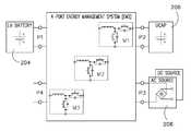
- FIG. 1is a schematic block diagram of an electric vehicle (EV) incorporating embodiments of the invention.
- EVelectric vehicle
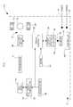
- FIG. 2is a schematic diagram of a configurable multi-port charger architecture according to an embodiment of the invention.
- FIG. 3is a table illustrating configurations as of the multi-port charger illustrated in FIG. 2 .
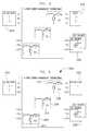
- FIG. 4is an illustration of the multi-port charger of FIG. 2 according to one configuration.
- FIG. 5is an illustration of the multi-port charger of FIG. 2 according to one configuration.
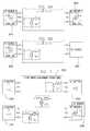
- FIGS. 6A and 6Bare illustrations of the multi-port charger of FIG. 5 according to alternate configurations.
- FIG. 7is an illustration of the multi-port charger of FIG. 2 according to one configuration.
- FIG. 8is an illustration of the multi-port charger of FIG. 2 according to one configuration.
- FIG. 9is an illustration of the multi-port charger of FIG. 2 according to one configuration.
- FIG. 10illustrates a typical pulse-width modulation (PWM) switching and waveform.
- FIG. 11illustrates a block diagram of a multi-port charger according to an embodiment of the invention.
- FIG. 12illustrates charging arrangements that may be selectively engaged and disengaged of the multi-port charger of FIG. 2 .
- FIG. 13illustrates a multi-port charger having a 1-phase AC source.
- FIG. 14illustrates a multi-port charger having a 3-phase AC source.
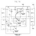
- FIG. 15illustrates energy flow in a multi-port charger according to a configuration of operation.
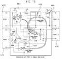
- FIG. 16illustrates energy flow in a multi-port charger according to a configuration of operation.
- FIG. 17illustrates a multi-port charger having an energy input from an internal combustion engine (ICE) according to an embodiment of the invention.
- ICEinternal combustion engine
- FIG. 1illustrates one embodiment of a hybrid electric vehicle (HEV) or electric vehicle (EV) 10 , such as an automobile, truck, bus, or off-road vehicle, for example, incorporating embodiments of the invention.
- Vehicle 10includes an energy storage and management system (ESMS) 11 internal combustion or heat engine 12 , a transmission 14 coupled to engine 12 , a differential 16 , and a drive shaft assembly 18 coupled between transmission 14 and differential 16 .
- ESMS 11is illustrated in a plug-in hybrid electric vehicle (PHEV), it is understood that ESMS 11 is applicable to any electric vehicle, such as a HEV or EV or other power electronic drives used to operate pulsed loads, according to embodiments of the invention.
- PHEVplug-in hybrid electric vehicle
- engine 12may be an internal combustion gasoline engine, an internal combustion diesel engine, an external combustion engine, or a gas turbine engine, as examples.
- ESMS 11includes an engine controller 20 provided to control operation of engine 12 .
- engine controller 20includes one or more sensors 22 that are configured to sense operating conditions of engine 12 .
- Sensors 22may include an rpm sensor, a torque sensor, an oxygen sensor, and a temperature sensor as examples.
- engine controller 20is configured to transmit or receive data from engine 12 .
- Vehicle 10also includes an engine speed sensor (not shown) that measures a crankshaft speed of engine 12 .
- speed sensormay measure engine crankshaft speed from a tachometer (not shown) in pulses per second, which may be converted to a revolutions per minute (rpm) signal.
- Vehicle 10also includes at least two wheels 24 that are coupled to respective ends of differential 16 .
- vehicle 10is configured as a rear wheel drive vehicle such that differential 16 is positioned near an aft end of vehicle 10 and is configured to drive at least one of the wheels 24 .
- vehicle 10may be configured as a front-wheel drive vehicle.
- transmission 14is a manually operated transmission that includes a plurality of gears such that the input torque received from engine 12 is multiplied via a plurality of gear ratios and transmitted to differential 16 through drive shaft assembly 18 .
- vehicle 10includes a clutch (not shown) configured to selectively connect and disconnect engine 12 and transmission 14 .
- Vehicle 10also includes an electromechanical device such as an electric motor or electric motor/generator unit 26 coupled along drive shaft assembly 18 between transmission 14 and differential 16 such that torque generated by engine 12 is transmitted through transmission 14 and through electric motor or electric motor/generator unit 26 to differential 16 .
- a speed sensor(not shown) may be included to monitor an operating speed of electric motor 26 .
- electric motor 26is directly coupled to transmission 14
- drive shaft assembly 18comprises one axle or drive shaft coupled to differential 16 .
- a hybrid drive control system or torque controller 28is provided to control operation of electric motor 26 and is coupled to motor/generator unit 26 .
- An energy storage system 30is coupled to torque controller 28 and comprises a low voltage energy storage or energy battery 32 , a high voltage energy storage or power battery 34 , and an ultracapacitor 36 , as examples.
- energy storage system 30may include a plurality of energy storage units as understood in the art such as sodium metal halide batteries, sodium nickel chloride batteries, sodium sulfur batteries, nickel metal hydride batteries, lithium ion batteries, lithium polymer batteries, nickel cadmium batteries, a plurality of ultracapacitor cells, a combination of ultracapacitors and batteries, or a fuel cell, as examples.
- An accelerator pedal 38 and brake pedal 40are also included in vehicle 10 . Accelerator pedal 38 is configured to send throttle command signals or accelerator pedal signals to engine controller 20 and torque control 28 .
- System 10includes a charger 42 coupled to energy storage units 32 - 36 of energy storage system 30 , according to embodiments of the invention.
- Charger 42may be coupled to multiple energy storage systems 32 - 36 , as illustrated and charger 42 may be coupled to one or multiple power input lines 44 , two of which are illustrated, according to embodiments of the invention. That is, charger 42 illustrates an embodiment of the invention, and charger 42 may be coupled to one or multiple energy storage systems, and charger 42 may be coupled to one or multiple power input systems 44 , according to embodiments illustrating use of the invention.
- Charger 42includes a controller 46 that is configured to selectively engage and disengage DC electrical devices or buck-boost modules of charger 42 as will be discussed.
- charger 42is illustrated as being coupled to energy storage systems 32 - 36 , and charger 42 is illustrated as coupled to one or multiple power input lines 44 , it is to be understood that embodiments of the invention are not to be so limited. Instead, it is to be understood that charger 42 may be coupled to multiple and varying types of energy storage systems and power inputs, some of which are illustrated in the following figures. Further, it is to be understood that there may be multiple chargers 42 per vehicle in parallel, or that there may be power systems applied to each wheel 24 of vehicle 10 , each having a charger 42 coupled thereto.
- energymay be provided to drive shaft assembly 18 from internal combustion or heat engine 12 via transmission 14 , and energy may be provided to drive shaft assembly 18 via drive control system 28 having energy drawn from energy storage system 30 that may include energy systems 32 - 36 .
- energymay be drawn for vehicle 10 boost or acceleration from, for instance a high voltage storage device 34 that may include a battery, as an example, or from ultracapacitor 36 .
- a high voltage storage device 34that may include a battery, as an example, or from ultracapacitor 36
- energymay be drawn for vehicle 10 via a low voltage storage device such as low voltage energy storage 32 .
- energymay be drawn from internal combustion or heat engine 12 in order to energy storage 30 or provide power to drive shaft assembly 18 as understood in the art.
- some systemsinclude a regenerative operation where energy may be recovered from a braking operation and used to re-charge energy storage 30 .
- some systemsmay not provide regenerative energy recovery from braking and some systems may not provide a heat engine such as internal combustion or heat engine 12 .
- energy storage 30periodically requires re-charging from an external source such as a 115 V household supply or a 230 V 3-phase source, as examples.
- the requirement to re-charge energy storage 30is particularly acute in a plug-in hybrid electric vehicle (PHEV) having no heat engine to provide power and an extended range of driving operation.
- PHEVplug-in hybrid electric vehicle
- embodiments of the inventionare flexible and configurable having a plurality of energy ports, and may be coupled to multiple power sources and source types in order to charge one or multiple energy storage types. Further, as will be illustrated, embodiments of the invention allow charging of an energy storage unit that is fully depleted and having a starting voltage that is below a voltage of a power source, and embodiments of the invention allow charging of an energy storage unit to voltages that are in excess of a voltage of the power source.
- the infrastructureshould provide typically 7 kW to achieve a state-of-charge (SOC) gain of 80% (assuming a 25 kWh battery) in a charging time of 2 or 3 hours (home charging).
- SOCstate-of-charge
- a more aggressive short stop fast charging scenarioe.g., a “gas station”
- significant higher power levelsmay be required to achieve a desired 80% SOC in 10 minutes.
- the vehicle interfaceneeds to be designed according to existing standards.
- a pilot signaldetermines by its duty cycle the maximum allowable power.
- the proposed systemprovides also single and or three phase AC input, high efficiency, low harmonics, nearly unity input power factor, low cost, low weight and safety interlocking of the equipment.
- the power factor correction (PFC) requirementmay be driven by IEC/ISO/IEEE line harmonic current regulations, as known in the art.
- an energy management systemwith an integrated charger unit consisting of three bi-directional buck-boost stages and a charger front end.
- the systemincludes also a charger module for high voltage DC and standard AC outlet charging.
- This inventionis applicable to conventional electric vehicles (EVs) as well as grid-charged hybrid electric vehicles (PHEVs).
- Grid-charged HEVsprovide the option to drive the vehicle for a certain number of miles (i.e., PHEV20, PHEV40, PHEV60).
- PHEV20, PHEV40, PHEV60a certain number of miles
- AERall-electric-range
- the charger front-end and interfaceit generally makes no difference if it is designed for an EV or PHEV application.
- the role of the DC/DC converteris an efficient energy transfer between two or more energy sources, reliable for continuous and peak power demands.
- inventions of the inventionare applicable to multiple electric vehicles, including all-electric and hybrid electric vehicles, as examples, designated generally and broadly as “EV”s.
- EVsmay include but are not limited to road vehicles, golf carts, trains, and the like, capable of having power systems that include an electric component for causing motion of the vehicle.
- ESMSenergy storage and management system
- EMSenergy management system
- ESMS 100such as charger 42 is illustrated having four energy ports 102 and three DC electrical conversion devices or buck-boost converters respectively as modules 1 , 2 , and 3 104 106 , 108 .
- buck-boost converters 104 - 108may be configured to operate in either a buck-mode by flowing electrical energy therethrough in a first direction 110 (illustrated with respect to buck-boost converter 104 , but equally applicable to converts 106 and 108 ), or a boost mode by flowing electrical energy in a second direction 112 (illustrated again with respect to buck-boost converter 104 , but equally applicable to converts 106 and 108 ).
- energy ports 102comprise a first energy port 114 configurable to have a first unit 116 attached or electrically coupled thereto.
- energy ports 102 energy port 118 120 122are configurable to have respective second unit 124 , third unit 126 , and fourth unit 128 attached or electrically coupled thereto.
- the chargeris entirely part of the vehicle design and mounted on-board.
- the integrated on-board chargeris capable of continuously adjusting an input current as a result of, for instance, a state-of-charge (SOC) of a device connected thereto for charging.
- SOCstate-of-charge
- the integrated charger energy management systemis equipped with a minimum number of standard components and is thus able to efficiently charge a plurality of energy storage systems and system types while having a minimum cost.
- each of the shown basic modulesis furthermore equipped with only one additional contactor to perform the different functions described below and to allow isolation of the ports.
- the configuration of the three individual modules M 1 to M 3 in FIG. 2 in conjunction with the appropriate charging algorithmallows energy transfer from arectified AC or directly from a DC source to different energy storage units connected to the ports of the ESMS.
- ESMS 100 of FIG. 2may be configured to charge up to three energy sources (to include low voltage energy batteries, high voltage power batteries, ultracapacitors, as examples) at the same time or simultaneously.
- ESMS 100may have modules therein configured to be interleaved in order to lower ripple current.
- ESMS 100also is capable of having multiple charging profiles as a function of SOC and temperature, as examples, for different battery technologies and storage device types.
- ESMS 100includes a centralized energy flow control that is centrally controlled by a controller such as controller 46 of FIG. 1 , and ESMS 100 is capable of managing a wide range of input and output voltages.
- ESMS 100 of FIGS. 1 and 2is configurable in multiple configurations as illustrated in FIG. 3 as a table 200 .
- Each configuration of ESMS 100may be selectable by contactors (not illustrated), as understood in the art, and energy flow is controlled by ESMS control algorithms, implemented in controller 46 of hybrid vehicle 10 , which can sense a presences of both energy storage devices and charging devices connected to ports 102 and adjust a flow of direction of energy, accordingly.
- the control algorithmsmay determine a voltage of each port to which an energy storage device or an electrical charging system (DC or rectified AC, as examples) is coupled, and operate ESMS 100 accordingly and based on the determined voltages, based on a measured frequency, or both (as examples).
- a benefit for including a rectifieris that even if DC is connected having the wrong polarity, the rectifier provides protection, even if a single phase rectifier is used or if a DC input is used to two of the 3-phase inputs for a 3-phase rectifier.
- EMS or ESMSincludes a low voltage battery 204 that is illustrated as connected to port 1 and an ultracapacitor bank 206 that is connected to port 2 .
- a single low voltage batterywhich represents the main energy storage unit for the EV, is connected to port 1 .
- the high voltage port 2is connected to a ultracapacitor bank or just to the DC link capacitors supplying the motor inverter.
- a charging unit 208is connected to port 3 , which may include either a DC source or a rectified AC source, according to embodiments of the invention. For this case if a charging input voltage at port 3 is higher than the energy battery 204 on port 1 , module 2 operates in buck mode.
- an energy/power batterymay instead be connected to port 2 .
- the remaining ports of the ESMSare left floating.
- two casesare considered depending on the instantaneous voltage level (SOC).
- SOCinstantaneous voltage level
- V 2voltage on port 2
- V 3voltage on port 3
- charger inputmodule 2 is permanently conducting and module 1 operates in boost mode.
- V 2 ⁇ V 3the battery is low in SOC (V 2 ⁇ V 3 ) module 2 operates in buck and module 1 in boost mode.
- an energy battery 250 on port 1represents the main energy storage unit for the EV, and a high voltage or power battery 252 is connected to port 2 .
- the integrated wide input voltage range chargerallows independent or simultaneously charging of both batteries 250 , 252 .
- the energy battery 250 on port 1has typically lower nominal voltages than the power (boost) battery 252 .
- boostthe power
- Module 2 254operates in buck mode and module 1 256 in boost mode. If the charging input 258 (DC or rectified AC) voltage is lower than the port 1 voltage, module 2 210 is turned on all time, module 1 256 boosts to port 2 voltage levels and module 3 260 charges the energy battery 250 on port 1 .
- FIG. 5illustrates a charging configuration from a rectified AC source, it may be misleading that merely relatively low voltages can be used for charging.
- the used portfor charging, port 3
- Port 4allows voltage up to a maximum of the overall charger system 262 , which may also be device-dependent.
- the illustrated configuration of FIG. 5is capable of relatively high voltage charging (e.g., IEC mode 4: 400 VDC).
- Embodiments of the inventionallow simultaneous charging of energy storage devices from more than one charging source.
- a second charging systemmay be interfaced with an ESMS, as illustrated in FIG. 6A .
- FIG. 6Aillustrates a cutaway lower portion of an ESMS.
- EV applicationsinclude two energy storage units, where port 4 is free of use, and a DC source or rectified AC source 264 .
- a rectified AC source 266may be coupled to port 4 , as illustrated, which allows faster charging from a second outlet.
- ports 3 and 4may be configured having respective electrical sources coupled thereto in order to charge storage devices that are coupled to, for instance, ports 1 and 2 of FIGS. 4 and 5 , as examples.
- FIG. 6Billustrates an alternate embodiment having rectified AC source 266 coupled thereto and a DC source 268 coupled to port 3 .
- One advantage of simultaneous charging with multiple sources such as an AC and a DC sourceis that high power rapid charging can be performed without a need to potentially increase the charge connector beyond what is already a standard (or expected may become a standard). For example, if the AC source and associated mating connectors is designed for level 2 , for example 22 kW, and the DC source and associated mating connectors are designed for level 3 or possibly level 4 DC rapid charging at, for instance, approximately 50 kW, then simultaneous charging from both AC and DC sources using embodiments of the invention can be performed at 72 kW by using standard charger connector units (assuming the charge station is able to support these power levels). Without this feature the maximum charge may be approximately 22 kW through the level 2 AC charge connector or 50 kW through the level 3 or level 4 DC charge connector.
- control within the ESMScould be implemented to allow the DC input to be connected to two of the three input terminals and controlled to operate at level 2 at up to 22 kW charge level, depending on the specific current capability for the connector.
- control within the ESMScould be implemented to allow the DC input to be connected to two of the three input terminals and controlled to operate at level 2 at up to 22 kW charge level, depending on the specific current capability for the connector.
- the vehicleis equipped with only AC charge connectors, for example a 3-phase level 2 AC input at 22 kW and single phase level 2 AC at approximately 7.4 kW, simultaneous charging using both AC connectors could be provided at approximately 29.4 kW levels.
- EMS or ESMS 300includes a first low voltage battery 302 is coupled to port 1 , a second low voltage battery 304 coupled to port 4 , a high voltage or boost battery 306 coupled to port 2 , and a DC source or rectified AC source 308 coupled to port 3 .
- source 308is a rectified DC source which can protect for inadvertently connecting across port 3 having an incorrect polarity.
- the second low voltage battery 304may be a backup energy battery which allows a higher level of redundancy for safety-critical applications.
- two boost batteries 310 , 312may be connected to respective ports 2 and 3 , which may be charged using a DC source or rectified AC source 314 coupled to port 4 .
- ESMS 316acts as a balancing stage while power delivery capability is similar to a parallel configuration.
- EMS or ESMS 350is coupled to energy devices in much the same fashion as that illustrated above with respect to FIG. 5 .
- a low voltage battery 352is coupled to port 1
- a high voltage battery 354is coupled to port 2
- a rectified AC source or DC source 356is coupled to port 3 .
- module 3 358is used to interleave during operation of ESMS 350 in order to minimize output current ripple.
- module 1 360in interleaved mode, power is transferred through two or three modules (module 1 360 , module 2 362 , and module 3 358 ) and produces a smaller output current ripple, compared to that of FIG. 5 , while at the same time reduces the size of magnetic and other components.
- module 1 360 and module 3 358are connected as shown in FIG. 9 .
- FIG. 10shows a typical pulse-width modulation (PWM) switching 364 and current waveform 366 .
- PWMpulse-width modulation
- the PWM to module 2 362is generally similar in frequency, just shifted in time by Ts/2 relative to the PWM signal of module 1 360 .
- three modulesoperate in interleaving, the PWM signals to the module 2 362 and module 3 358 are shifted, respectively, by Ts/3 and 2 Ts/3.
- FIG. 11illustrates a block diagram of a multi-port ESMS according to an embodiment of the invention.
- contactors illustrated in FIG. 11may be controlled according to the table illustrated in FIG. 12 .
- ESMS 400illustrates a first buck-boost module 402 , a second buck-boost module 404 , and a third buck-boost module 406 .
- ESMS 400also illustrates port 1 408 having a low voltage battery coupled thereto, port 2 410 having a high voltage unit coupled thereto, port 3 412 having a rectified AC or DC voltage coupled thereto, and port 4 414 having a low voltage ultracapacitor coupled thereto.
- energy storage devices and an energy chargerare coupled to ESMS 400 in order to illustrate operation according to one configuration.
- ESMS 400may be configured in numerous arrangements in order to accommodate multiple charger/energy storage arrangements.
- ESMS 400includes contactors KU 416 , KV 418 , KW 420 , UPOS 422 , and M 424 which may be selectively engaged or disengaged in order to accomplish configurations for charging, according to the illustrations above.
- Each of the three buck-boost modules 402 , 404 , 406includes an IGBT leg (upper and lower switch) and an inductor.
- the high voltage DC busis buffered by a number of power capacitors.
- Each buck-boost converter stage outputis equipped with a current sensor, which measures an inductor current. Voltage limits show at port 3 are originated by typical single-phase AC outlet voltages in both the US and Europe.
- ESMS 400uses contactors as main bus and individual module switches.
- the pre-charge circuitis realized using two power resistors (e.g., 120 ohm, 100 W, RH-50) and a contactor or FET.
- An additional contactor(UPOS 422 in FIG. 11 ) serves in two cases. One is under a certain SOC condition of a battery at port 1 , and the second if interleaving of module 1 and module 3 is enabled.
- FIG. 11illustrates voltage and current sense points of ESMS 400 having an integrated charger.
- control of specific charging operationsmay be by selective engagement and disengagement of contactors 416 - 424 .
- multi-port energy managementis fully functional. Even if for some reason it is desired to equip the system with a separate charger, the multi-port ESMS still performs its function, which is at a minimum energy management between ports 1 , 2 and 4 . After completed pre-charge of the DC link capacitors, the ESMS sets the individual phase state machines into manual mode and sets the current commands and starts regulating after a sanity check of the contactor states.
- port 3 of the illustrated ESMS 450may be charged from a 1-phase AC source 452 , thus a simple high-power factor boost pre-regulator can be realized according to an embodiment of the invention.
- ESMS 450is connected to a single-phase rectifier on port 3 454 , for instance, as shown in FIG. 13 , module 1 456 and module 2 458 are used by operating in a high-power factor regulator mode.
- FIG. 13illustrates a simple approach of a rectified AC source having a power factor correction (PFC) pre-regulator, C in is a small high frequency bypass capacitor, and C out is a bulk storage capacitor or DC bus capacitor.
- PFCpower factor correction
- the control in AC modeis performing.
- Firstis to limit the maximum charging current drawn from the utility grid to the specified maximum that is limited by the line or circuit breaker.
- the PFC boost stageshapes the current to minimize the phase angle between input current and input voltage.
- the circuit illustratedis essentially a boost converter with wide input range that is capable of precisely controling an input current (current shaping).
- the current in waveshape and phase to the input voltageis controlled instantaneously.
- a relatively large capacitor at the output of the boost stagesupplies short peak energy demands, while the input capacitor is reduced to a few microfarads.
- EMI filter componentsare standards components and will be connected between the corresponding front-end and the mechanical interface to the HVSE, as understood in the art.
- ESMS 450can include a rectifier front-end 460 for a 3-phase charger input 462 designed in a similar fashion as that illustrated in FIG. 13 .
- an integrated charger configuration of ESMS port 3 of FIGS. 13 and 14can be used as a charger input.
- FIGS. 15 and 16energy flow for two configurations of charging is illustrated.
- energyis to flow from a charger (not illustrated) positioned on port 3 464 , to module 2 466 , and to module 1 468 operating in boost mode.
- a DC sourcemay be boosted to a high-voltage output on port 2 470 , by ensuring KV and KW are open.
- port 1 472 and port 4 474may be charged simultaneously from a DC source (not shown) coupled to port 3 476 .
- a DC sourcenot shown
- Two casesmay be considered regarding FIG. 16 , as examples.
- Case 1Input voltage at port 3 476 is higher than battery voltage at port 1 472 .
- module 2 478operates in buck mode and the current IL 4 480 in LU is regulated.
- Contactors KU 482 and KV 484are closed, while M 486 , KW 488 and UPOS 490 are open.
- Case 2Input voltage at port 3 476 is lower than battery voltage at port 1 472 .
- contactors KU 482 , M 486 and UPOS 490are closed, while KV 484 and KW 488 are open.
- Module 2 478is inactive (M2U is permanently on), module 1 492 operates in boost mode to boost the low input voltage up to some higher level.
- Module 3 494bucks this voltage back to the set voltage of the energy battery at port 1 472 .
- the current IL 2 496 in LWis controlled in a closed loop fashion.
- energy and e-motor drivetrainstypically include components from different vendors. As a result many units are duplicated, with many single point failure possibilities in the system. Thus, the integration of functions into one instead of three or four management units will result in a reliability improvement, according to embodiments of the invention. From the perspective of a battery manufacturer for example, where good knowledge of the battery cell behavior is available, an integration of ESMS and charger function is desirable. Further, although an EV is specifically mentioned, as mentioned, embodiments of the invention may be used for a PHEV or series hybrid as well. In this case one of the ports on the left could be used to transfer energy from an Auxillary Power Unit (APU), that can operate in charge sustaining mode.
- APUAuxillary Power Unit
- ESMS 500includes an electrical output from an internal combustion engine (ICE) 502 coupled to port 1 , and either a LV battery 506 or a rectified AC source 506 coupled to port 4 .
- the electrical output from ICE 502may be an alternator that outputs DC electrical power, in one embodiment.
- a power battery 508is coupled to port 2 and an AC source or DC source 510 may be coupled to port 3 .
- ICE 502provides flexibility for extended vehicle range while providing an ability to charge energy storage system from separate ports.
- a technical contribution for the disclosed apparatusis that it provides for a controller implemented technique for charging energy storage devices of an electric vehicle.
- an energy storage management systemincludes one or more energy storage devices coupled to a vehicle drivetrain and configured to store DC energy, a power electronic conversion system having a plurality of energy ports, the power electronic conversion system comprising a plurality of DC electrical converters, each DC electrical converter configured to step up and to step down a DC voltage, wherein each of the plurality of energy ports is coupleable to each of the one or more energy storage devices and each of the plurality of energy ports is coupleable to an electrical charging system.
- the EVincludes a controller configured to determine a voltage of each energy port having either an energy storage device or a DC electrical charging system coupled thereto, and electrically connect a first energy port to a second energy port of at least two of the energy ports such that at least one of the DC electrical converters either steps up or steps down an input DC voltage based on the determined voltage of each energy port.
- a method of fabricating an energy storage and management systemincludes coupling one or more energy storage devices to a vehicle powertrain, fabricating a charging device having a plurality of buck-boost converters, attaching the charging device to the vehicle, the charging device comprising a plurality of energy ports, each of the plurality of energy ports coupleable to each of the one or more energy storage devices, sensing a voltage across each of the plurality of energy ports, determining if an energy storage device and an electrical charging system is coupled to any of the plurality of energy ports based on the sensed voltage, and electrically connecting the electrical charging system to any of the plurality of energy ports having an energy storage device by selectively directing electrical current to flow through one or more of the plurality of buck-boost converters.
- ESMSenergy storage and management system
- a non-transitory computer readable storage mediumpositioned on an energy storage and management system (ESMS) and having stored thereon a computer program comprising instructions which when executed by a computer cause the computer to determine a voltage of each energy port of a multi-port power conversion system that is positioned on the ESMS, and electrically connect at least two of the energy ports such that electrical energy passes from a first of the at least two energy ports to a second of the at least two energy ports and through at least two buck-boost converters, a first buck-boost converter of the at least two buck-boost converters configured to operate in a boost mode, and a second buck-boost converter of the at least two buck-boost converters configured to operate in a buck mode.
- ESMSenergy storage and management system
Landscapes
- Engineering & Computer Science (AREA)
- Power Engineering (AREA)
- Transportation (AREA)
- Mechanical Engineering (AREA)
- Sustainable Energy (AREA)
- Sustainable Development (AREA)
- Life Sciences & Earth Sciences (AREA)
- Charge And Discharge Circuits For Batteries Or The Like (AREA)
- Electric Propulsion And Braking For Vehicles (AREA)
- Hybrid Electric Vehicles (AREA)
- Arrangement Or Mounting Of Propulsion Units For Vehicles (AREA)
- Control Of Charge By Means Of Generators (AREA)
- Secondary Cells (AREA)
Abstract
Description
Claims (28)
Priority Applications (12)
| Application Number | Priority Date | Filing Date | Title |
|---|---|---|---|
| US12/940,085US8378623B2 (en) | 2010-11-05 | 2010-11-05 | Apparatus and method for charging an electric vehicle |
| EP21191611.9AEP3981638B1 (en) | 2010-11-05 | 2011-11-01 | Apparatus and method for charging an electric vehicle |
| EP11187387.3AEP2450221B1 (en) | 2010-11-05 | 2011-11-01 | Apparatus and method for charging an electric vehicle |
| ES11187387TES2892249T3 (en) | 2010-11-05 | 2011-11-01 | Apparatus and method for charging an electric vehicle |
| ES21191611TES2975094T3 (en) | 2010-11-05 | 2011-11-01 | Apparatus and method for charging an electric vehicle |
| JP2011239869AJP5908254B2 (en) | 2010-11-05 | 2011-11-01 | Apparatus and method for charging an electric vehicle |
| BRPI1104811-5ABRPI1104811B1 (en) | 2010-11-05 | 2011-11-04 | ENERGY AND STORAGE CONTROL SYSTEM |
| CN201510494062.7ACN105034830B (en) | 2010-11-05 | 2011-11-07 | For the apparatus and method to electric vehicle charging |
| CN201110381828.2ACN102452325B (en) | 2010-11-05 | 2011-11-07 | Apparatus and method for charging an electric vehicle |
| JP2015198092AJP6188090B2 (en) | 2010-11-05 | 2015-10-06 | Apparatus and method for charging an electric vehicle |
| JP2017148827AJP6553133B2 (en) | 2010-11-05 | 2017-08-01 | Apparatus and method for charging an electric vehicle |
| JP2019123413AJP7051758B2 (en) | 2010-11-05 | 2019-07-02 | Devices and methods for charging electric vehicles |
Applications Claiming Priority (1)
| Application Number | Priority Date | Filing Date | Title |
|---|---|---|---|
| US12/940,085US8378623B2 (en) | 2010-11-05 | 2010-11-05 | Apparatus and method for charging an electric vehicle |
Publications (2)
| Publication Number | Publication Date |
|---|---|
| US20120112693A1 US20120112693A1 (en) | 2012-05-10 |
| US8378623B2true US8378623B2 (en) | 2013-02-19 |
Family
ID=45047584
Family Applications (1)
| Application Number | Title | Priority Date | Filing Date |
|---|---|---|---|
| US12/940,085Active2031-10-14US8378623B2 (en) | 2010-11-05 | 2010-11-05 | Apparatus and method for charging an electric vehicle |
Country Status (6)
| Country | Link |
|---|---|
| US (1) | US8378623B2 (en) |
| EP (2) | EP3981638B1 (en) |
| JP (4) | JP5908254B2 (en) |
| CN (2) | CN105034830B (en) |
| BR (1) | BRPI1104811B1 (en) |
| ES (2) | ES2892249T3 (en) |
Cited By (35)
| Publication number | Priority date | Publication date | Assignee | Title |
|---|---|---|---|---|
| US20120212174A1 (en)* | 2009-08-21 | 2012-08-23 | Jfe Engineering Corporation | Quick charging device |
| US20130038271A1 (en)* | 2011-08-09 | 2013-02-14 | Hyundai Motor Company | Control method of hybrid vehicle |
| US20130088196A1 (en)* | 2011-10-11 | 2013-04-11 | Delta Electronics, Inc. | High-voltage battery charging system and charger with such charging system |
| US20130106195A1 (en)* | 2011-10-31 | 2013-05-02 | Ruediger Soeren Kusch | Apparatus and method for rapidly charging an electric vehicle |
| US20130300126A1 (en)* | 2012-05-10 | 2013-11-14 | Samsung Sdi Co., Ltd. | Range Extender, Drive and Motor Vehicle |
| US8705527B1 (en) | 2011-01-14 | 2014-04-22 | Cisco Technology, Inc. | System and method for internal networking, data optimization and dynamic frequency selection in a vehicular environment |
| US8725330B2 (en) | 2010-06-02 | 2014-05-13 | Bryan Marc Failing | Increasing vehicle security |
| US20140368160A1 (en)* | 2012-01-20 | 2014-12-18 | Dirk Reichow | Vehicle Electric System, Device for Controlling a Vehicle Electric System, and Vehicle with a Device |
| US20150042159A1 (en)* | 2013-08-12 | 2015-02-12 | Hyundai Motor Company | Converter apparatus and method of electric vehicle |
| US20150280487A1 (en)* | 2012-11-16 | 2015-10-01 | Panasonic Intellectual Property Management Co., Ltd. | Vehicle-mounted power source device |
| US20150291052A1 (en)* | 2012-11-16 | 2015-10-15 | Panasonic Intellectual Property Management Co., Ltd. | Vehicle-mounted power source device |
| US20150311831A1 (en)* | 2012-11-07 | 2015-10-29 | Volvo Truck Corporation | Power supply device |
| US9643513B2 (en) | 2014-12-08 | 2017-05-09 | General Electric Company | Propelling system and energy management system and methods |
| US20170182910A1 (en)* | 2014-04-24 | 2017-06-29 | Audi Ag | Multi-battery system for increasing the electric range |
| US9796277B2 (en) | 2015-02-27 | 2017-10-24 | GM Global Technology Operations LLC | Electric bike extended range battery power electronics and control |
| US9821668B2 (en) | 2012-05-21 | 2017-11-21 | General Electric Company | Method and apparatus for charging multiple energy storage devices |
| US9895983B2 (en) | 2013-10-11 | 2018-02-20 | General Electric Company | Propulsion system and method for driving a vehicle |
| US9899843B2 (en) | 2015-03-31 | 2018-02-20 | General Electric Company | Energy storage system with range extender and energy management and control method |
| US10056755B2 (en) | 2015-03-31 | 2018-08-21 | General Electric Company | Multi-source energy storage system and energy management and control method |
| US10666045B2 (en) | 2011-10-28 | 2020-05-26 | General Electric Company | System for selectively coupling an energy source to a load and method of making same |
| US10828989B2 (en)* | 2016-09-20 | 2020-11-10 | Voith Patent Gmbh | Method for operating a hybrid vehicle |
| US10843578B2 (en) | 2019-03-22 | 2020-11-24 | Caterpillar Inc. | Configuration for battery powered electric drive load haul dump |
| US20210078442A1 (en)* | 2019-09-13 | 2021-03-18 | GM Global Technology Operations LLC | Charging architecture for reconfigurable battery pack using solid-state and contactor switches |
| US11052784B2 (en)* | 2017-11-08 | 2021-07-06 | Eaton Intelligent Power Limited | Power distribution unit and fuse management for an electric mobile application |
| US11070049B2 (en) | 2017-11-08 | 2021-07-20 | Eaton Intelligent Power Limited | System, method, and apparatus for power distribution in an electric mobile application using a combined breaker and relay |
| US11108225B2 (en) | 2017-11-08 | 2021-08-31 | Eaton Intelligent Power Limited | System, method, and apparatus for power distribution in an electric mobile application using a combined breaker and relay |
| US11207993B2 (en)* | 2017-08-07 | 2021-12-28 | Vitesco Technologies GmbH | Storage-battery charging device for a motor vehicle, method for operating an on-board storage-battery charging device, high-voltage vehicle electrical system and use of a storage-battery charging device |
| US11368031B2 (en) | 2017-11-08 | 2022-06-21 | Eaton Intelligent Power Limited | Power distribution and circuit protection for a mobile application having a high efficiency inverter |
| US20220271539A1 (en)* | 2021-02-24 | 2022-08-25 | Mclaren Automotive Limited | Battery system |
| US11453301B2 (en) | 2019-08-28 | 2022-09-27 | SparkCharge, Inc. | Electric vehicle charging apparatus, system and methods |
| US11554639B2 (en)* | 2019-01-31 | 2023-01-17 | Carrier Corporation | Power module device and transport refrigeration system |
| US11605851B1 (en) | 2021-09-21 | 2023-03-14 | Knoetik Solutions, Inc. | Systems, methods and apparatus for improving rechargeable energy storage devices and integrated circuits |
| US11670937B2 (en) | 2019-02-22 | 2023-06-06 | Eaton Intelligent Power Limited | Coolant connector having a chamfered lip and fir tree axially aligned with at least one o-ring |
| US11707993B2 (en) | 2021-07-27 | 2023-07-25 | Caterpillar Inc. | System and method for charging battery units of work machines |
| US12088131B2 (en) | 2019-07-15 | 2024-09-10 | Eaton Intelligent Power Limited | Power distribution and circuit protection for a mobile application having a high efficiency inverter |
Families Citing this family (63)
| Publication number | Priority date | Publication date | Assignee | Title |
|---|---|---|---|---|
| KR101194485B1 (en)* | 2010-10-19 | 2012-10-24 | 삼성전기주식회사 | Charging equipment of Variable frequency control for power factor |
| KR20120061281A (en)* | 2010-12-03 | 2012-06-13 | 에스케이이노베이션 주식회사 | System and Method for providing reactive power using electric car battery |
| US9035595B2 (en)* | 2011-06-29 | 2015-05-19 | Caterpillar Inc. | Integral electric power/compact construction equipment system |
| KR101263463B1 (en)* | 2011-09-02 | 2013-05-10 | 주식회사 만도 | Apparatus for charging battery |
| US9348381B2 (en) | 2011-10-19 | 2016-05-24 | Zeco Systems Pte Ltd | Methods and apparatuses for charging of electric vehicles |
| US9118201B2 (en) | 2012-05-08 | 2015-08-25 | General Electric Company | Systems and methods for energy transfer control |
| EP2867975B1 (en)* | 2012-06-27 | 2020-04-15 | BYD Company Limited | Charging system, vehicle comprising the same and method for controlling charging vehicle with the same |
| US9634508B2 (en)* | 2012-09-13 | 2017-04-25 | Stem, Inc. | Method for balancing frequency instability on an electric grid using networked distributed energy storage systems |
| ITFI20130027A1 (en)* | 2013-02-04 | 2014-08-05 | Paolo Canova | DEVICE FOR TESTING AND CONDITIONING BATTERIES, PROVIDED WITH MEANS OF RECOVERY OF BATTERY DISCHARGE ENERGY. |
| US9174525B2 (en) | 2013-02-25 | 2015-11-03 | Fairfield Manufacturing Company, Inc. | Hybrid electric vehicle |
| US9764643B2 (en) | 2013-03-21 | 2017-09-19 | Toyota Jidosha Kabushiki Kaisha | Vehicle |
| JP6117599B2 (en)* | 2013-04-08 | 2017-04-19 | 本田技研工業株式会社 | Battery charger for vehicle |
| TWI556538B (en)* | 2013-06-04 | 2016-11-01 | 台達電子工業股份有限公司 | Power supply system and method for converting power thereof |
| KR101459968B1 (en)* | 2013-11-19 | 2014-11-10 | 현대자동차주식회사 | Charging demand verification method of a Electric Vehicle and the system thereof |
| EP3109090A4 (en)* | 2014-02-20 | 2018-03-07 | Coordenação Dos Programas De Pós Graduação De Engenharia Da Universidade Federal Do Rio De Janeiro | Smart energy management systems for electric and hybrid electric vehicles with bidirectional connection, smart energy management system for an energy generator, method for managing energy in a smart energy management system and method for controlling the operation of an energy generator |
| JP5915675B2 (en)* | 2014-02-21 | 2016-05-11 | トヨタ自動車株式会社 | Electric vehicle |
| JP6322088B2 (en)* | 2014-08-29 | 2018-05-09 | 株式会社日立製作所 | Battery system |
| JP6172114B2 (en)* | 2014-10-28 | 2017-08-02 | トヨタ自動車株式会社 | Hybrid car |
| KR101755798B1 (en)* | 2015-06-30 | 2017-07-07 | 현대자동차주식회사 | Device and method for controlling battery charge and discharge quantity in eco-friendly vehicle |
| DE102016103011A1 (en)* | 2016-02-22 | 2017-08-24 | Dr. Ing. H.C. F. Porsche Aktiengesellschaft | Method and device for operating charging stations |
| US11088549B2 (en)* | 2016-03-22 | 2021-08-10 | Intersil Americas LLC | Multiple chargers configuration in one system |
| US10594152B1 (en) | 2016-03-25 | 2020-03-17 | Intersil Americas LLC | Method and system for a battery charger |
| CN106026322B (en)* | 2016-07-22 | 2022-04-29 | 中国电力科学研究院 | A plug-and-play system control method for charging an electric vehicle equipped with an energy storage battery |
| DE102017201155A1 (en)* | 2017-01-25 | 2018-07-26 | Robert Bosch Gmbh | Arrangement for transmitting electrical energy, drive train and working device |
| CN107054260A (en)* | 2017-04-24 | 2017-08-18 | 北京新能源汽车股份有限公司 | Storage battery control method and system and electric automobile |
| JP7398961B2 (en) | 2017-06-12 | 2023-12-15 | ティーエーイー テクノロジーズ, インコーポレイテッド | Multi-level multi-quadrant hysteresis current controller and method for its control |
| EP3639361A4 (en) | 2017-06-16 | 2021-03-24 | TAE Technologies, Inc. | Multi-level hysteresis voltage controllers for voltage modulators and methods for control thereof |
| CN109204025B (en)* | 2017-06-30 | 2024-02-20 | 宇通客车股份有限公司 | Vehicle-mounted charging device and new energy vehicle |
| FR3069497B1 (en)* | 2017-07-26 | 2019-08-02 | Psa Automobiles Sa | METHOD FOR A HYBRID VEHICLE FOR CONTROLLING A RECHARGING ALTERNATOR OF A BATTERY OF A FLIGHT NETWORK |
| DE102017217729B4 (en) | 2017-10-05 | 2020-01-23 | Audi Ag | Energy supply device for providing electrical energy for at least one terminal and method for operating an energy supply device |
| US10882415B2 (en)* | 2017-12-04 | 2021-01-05 | General Electric Company | System and method of pre-charge testing to prevent misuse of electric vehicle charging station |
| JP2021044850A (en)* | 2017-12-27 | 2021-03-18 | 日本電産トーソク株式会社 | Motor control device |
| KR20200135399A (en) | 2018-03-22 | 2020-12-02 | 티에이이 테크놀로지스, 인크. | Systems and methods for power management and control |
| KR102530939B1 (en)* | 2018-04-09 | 2023-05-11 | 현대자동차주식회사 | Power converting system for vehicle |
| IT201800004702A1 (en)* | 2018-04-19 | 2019-10-19 | SYSTEM AND METHOD OF CHARGING A DIRECT CURRENT ELECTRIC VEHICLE | |
| JP7115082B2 (en) | 2018-07-09 | 2022-08-09 | 株式会社デンソー | Charging control device and charging control system |
| JP2020058131A (en) | 2018-10-01 | 2020-04-09 | 株式会社Soken | Drive system |
| CN109808524B (en)* | 2019-03-19 | 2024-06-11 | 南京新驿科技发展有限公司 | Power supply trailer system of pure electric vehicle and control method thereof |
| EP3949063A4 (en) | 2019-03-29 | 2023-03-01 | TAE Technologies, Inc. | MODULE-BASED ENERGY SYSTEMS WITH CONVERTER SOURCE MODULES AND METHODS THEREOF |
| US12278508B2 (en)* | 2019-06-17 | 2025-04-15 | Renesas Electronics America Inc. | Single inductor multiple output charger for multiple battery applications |
| JP7074725B2 (en)* | 2019-07-18 | 2022-05-24 | 矢崎総業株式会社 | Power supply system, DCDC converter device, and charging method |
| US20210066953A1 (en)* | 2019-08-28 | 2021-03-04 | Delphi Automotive Systems Luxembourg Sa | Systems and methods for smooth start up of vehicle onboard battery charger |
| CN110556901A (en)* | 2019-09-23 | 2019-12-10 | 台达电子企业管理(上海)有限公司 | vehicle-mounted charging and discharging system |
| KR102717297B1 (en)* | 2019-10-08 | 2024-10-16 | 현대자동차주식회사 | Battery charger for electric vehicle |
| WO2021104664A1 (en)* | 2019-11-29 | 2021-06-03 | Sew-Eurodrive Gmbh & Co. Kg | Installation comprising a stored energy source and an electric motor which can be fed by an inverter, and method for operating an installation |
| AU2021254739A1 (en) | 2020-04-14 | 2022-12-01 | Tae Technologies, Inc. | Modular cascaded energy systems with a cooling apparatus and with replaceable energy source capability |
| CA3191441A1 (en) | 2020-04-14 | 2021-10-21 | Tae Technologies, Inc. | Systems, devices, and methods for charging and discharging module-based cascaded energy systems |
| AU2021271701A1 (en)* | 2020-05-14 | 2022-12-22 | Tae Technologies, Inc. | Systems, devices, and methods for rail-based and other electric vehicles with modular cascaded energy systems |
| US20240359595A1 (en)* | 2020-08-24 | 2024-10-31 | Tae Technologies, Inc. | Modular Cascaded Energy Systems with a Cooling Apparatus and with Replaceable Energy Source Capability |
| US11923782B2 (en) | 2020-09-28 | 2024-03-05 | Tae Technologies, Inc. | Multi-phase module-based energy system frameworks and methods related thereto |
| JP7203795B2 (en)* | 2020-09-28 | 2023-01-13 | 本田技研工業株式会社 | MOBILE BODY CONTROL DEVICE, CONTROL METHOD THEREOF, AND MOBILE BODY |
| JP2023543834A (en) | 2020-09-30 | 2023-10-18 | ティーエーイー テクノロジーズ, インコーポレイテッド | Systems, devices, and methods for intraphase and interphase equilibrium in module-based cascaded energy systems |
| CN112238763B (en)* | 2020-10-23 | 2022-05-13 | 中车株洲电力机车有限公司 | Charging circuit and control device and control method thereof |
| EP4122073A4 (en)* | 2020-10-30 | 2023-12-27 | Velocity Magnetics, Inc. | Insulated-gate bipolar transistor (igbt) rectifier for charging ultra-capacitors |
| US20240075838A1 (en)* | 2020-12-23 | 2024-03-07 | Velocity Magnetics, Inc. | Method, System, and Computer Program Product for Charging an Electric Vehicle Using Ultra-Capacitors |
| CA3207256A1 (en) | 2021-01-13 | 2022-07-21 | Tae Technologies, Inc. | Systems, devices, and methods for module-based cascaded energy systems |
| JP2024528571A (en) | 2021-07-07 | 2024-07-30 | ティーエーイー テクノロジーズ, インコーポレイテッド | Systems, devices, and methods for a modular-based cascaded energy system configured to interface with renewable energy sources - Patents.com |
| DE102021128800A1 (en)* | 2021-11-05 | 2023-05-11 | Dr. Ing. H.C. F. Porsche Aktiengesellschaft | Method for determining the aging condition of at least one cell of a battery |
| CN114560091B (en)* | 2022-03-07 | 2024-02-06 | 西北工业大学 | Multi-electric aircraft hybrid energy management system and method based on model prediction |
| CN115140059B (en)* | 2022-07-19 | 2025-08-12 | 山东大学 | Hybrid electric vehicle energy management method and system based on multi-objective optimization |
| DE102022212442A1 (en)* | 2022-11-22 | 2024-05-23 | Robert Bosch Gesellschaft mit beschränkter Haftung | DC-DC converter, multi-voltage network, electric vehicle and method for operating a multi-voltage network |
| US20240186885A1 (en)* | 2022-12-01 | 2024-06-06 | Rivian Ip Holdings, Llc | Systems and methods for energy delivery |
| JP7743597B1 (en) | 2024-12-23 | 2025-09-24 | 九州電力株式会社 | Charging system |
Citations (11)
| Publication number | Priority date | Publication date | Assignee | Title |
|---|---|---|---|---|
| US5373195A (en) | 1992-12-23 | 1994-12-13 | General Electric Company | Technique for decoupling the energy storage system voltage from the DC link voltage in AC electric drive systems |
| US5589743A (en) | 1995-03-03 | 1996-12-31 | General Electric Company | Integrated cranking inverter and boost converter for a series hybrid drive system |
| US5903449A (en) | 1998-06-09 | 1999-05-11 | General Electric Company | Bi-directional power control system for voltage converter |
| US5929595A (en) | 1997-11-21 | 1999-07-27 | Lockheed Martin Corporation | Hybrid electric vehicle with traction motor drive allocated between battery and auxiliary source depending upon battery charge state |
| US6331365B1 (en) | 1998-11-12 | 2001-12-18 | General Electric Company | Traction motor drive system |
| US6724100B1 (en) | 2000-09-08 | 2004-04-20 | Ford Motor Company | HEV charger/generator unit |
| US20080055940A1 (en)* | 2006-08-25 | 2008-03-06 | Lawson Labs, Inc. | Bi-polar bi-directional energy balancing power-conversion engine |
| US7427450B2 (en) | 2004-12-10 | 2008-09-23 | General Motors Corporation | Hybrid fuel cell system with battery capacitor energy storage system |
| US7517298B2 (en) | 2006-09-05 | 2009-04-14 | Ford Global Technologies, Llc | Power-on downshift control for a hybrid electric vehicle powertrain |
| US7559388B2 (en) | 1998-09-14 | 2009-07-14 | Paice Llc | Hybrid vehicles |
| US20090242291A1 (en)* | 2008-03-25 | 2009-10-01 | Fuji Jukogyo Kabushiki Kaisha | Electric vehicle |
Family Cites Families (26)
| Publication number | Priority date | Publication date | Assignee | Title |
|---|---|---|---|---|
| JP3448850B2 (en)* | 1997-10-13 | 2003-09-22 | 株式会社デンソー | Hybrid electric vehicle charging system |
| US7256516B2 (en)* | 2000-06-14 | 2007-08-14 | Aerovironment Inc. | Battery charging system and method |
| JP2002014749A (en)* | 2000-06-30 | 2002-01-18 | Mitsubishi Electric Corp | Power system |
| JP3755043B2 (en)* | 2001-09-10 | 2006-03-15 | 有限会社サンブリッジ | Chargeable / dischargeable power supply |
| US7339353B1 (en)* | 2004-03-10 | 2008-03-04 | Quallion Llc | Power system for managing power from multiple power sources |
| US7780562B2 (en)* | 2006-01-09 | 2010-08-24 | General Electric Company | Hybrid vehicle and method of assembling same |
| US7595597B2 (en)* | 2006-01-18 | 2009-09-29 | General Electric Comapany | Vehicle propulsion system |
| JP2007228753A (en)* | 2006-02-24 | 2007-09-06 | Toyota Motor Corp | Electric vehicle |
| US7599196B2 (en)* | 2006-06-06 | 2009-10-06 | Ideal Power Converters, Inc. | Universal power converter |
| JP5011874B2 (en)* | 2006-07-31 | 2012-08-29 | ミツミ電機株式会社 | Bi-directional converter and electronic device |
| US7859202B2 (en)* | 2007-03-09 | 2010-12-28 | Illinois Institute Of Technology | Power management for multi-module energy storage systems in electric, hybrid electric, and fuel cell vehicles |
| JP2008296669A (en)* | 2007-05-30 | 2008-12-11 | Daihatsu Motor Co Ltd | Charging apparatus for hybrid automobile |
| JP4962184B2 (en) | 2007-07-18 | 2012-06-27 | トヨタ自動車株式会社 | Vehicle power supply |
| JP4305553B2 (en) | 2007-10-23 | 2009-07-29 | トヨタ自動車株式会社 | Electric vehicle |
| JP4798120B2 (en)* | 2007-11-07 | 2011-10-19 | トヨタ自動車株式会社 | Vehicle power system |
| JP2009148073A (en)* | 2007-12-14 | 2009-07-02 | Mazda Motor Corp | Method and device for charging battery |
| JP4807590B2 (en)* | 2007-12-28 | 2011-11-02 | 本田技研工業株式会社 | Control device for hybrid vehicle |
| US8358107B2 (en)* | 2007-12-31 | 2013-01-22 | Intel Corporation | Bidirectional power management techniques |
| JP2009194986A (en)* | 2008-02-13 | 2009-08-27 | Toyota Motor Corp | Vehicle charging device |
| JP4315232B1 (en) | 2008-03-17 | 2009-08-19 | トヨタ自動車株式会社 | Electric vehicle |
| JP2010028886A (en)* | 2008-07-15 | 2010-02-04 | Toyota Motor Corp | System for controlling charge and discharge of energy storage device |
| US8080973B2 (en)* | 2008-10-22 | 2011-12-20 | General Electric Company | Apparatus for energy transfer using converter and method of manufacturing same |
| JP5187152B2 (en)* | 2008-11-17 | 2013-04-24 | トヨタ自動車株式会社 | Vehicle power supply system and vehicle |
| EP2395624B1 (en) | 2009-02-03 | 2018-06-13 | Toyota Jidosha Kabushiki Kaisha | Charging system for vehicle |
| JP4800402B2 (en) | 2009-03-18 | 2011-10-26 | 株式会社豊田中央研究所 | Multi-phase converter for on-vehicle use |
| EP2428387A4 (en)* | 2009-04-23 | 2017-03-22 | Toyota Jidosha Kabushiki Kaisha | Power supply system of electric vehicle and control method thereof |
- 2010
- 2010-11-05USUS12/940,085patent/US8378623B2/enactiveActive
- 2011
- 2011-11-01EPEP21191611.9Apatent/EP3981638B1/enactiveActive
- 2011-11-01EPEP11187387.3Apatent/EP2450221B1/enactiveActive
- 2011-11-01JPJP2011239869Apatent/JP5908254B2/enactiveActive
- 2011-11-01ESES11187387Tpatent/ES2892249T3/enactiveActive
- 2011-11-01ESES21191611Tpatent/ES2975094T3/enactiveActive
- 2011-11-04BRBRPI1104811-5Apatent/BRPI1104811B1/enactiveIP Right Grant
- 2011-11-07CNCN201510494062.7Apatent/CN105034830B/enactiveActive
- 2011-11-07CNCN201110381828.2Apatent/CN102452325B/enactiveActive
- 2015
- 2015-10-06JPJP2015198092Apatent/JP6188090B2/enactiveActive
- 2017
- 2017-08-01JPJP2017148827Apatent/JP6553133B2/enactiveActive
- 2019
- 2019-07-02JPJP2019123413Apatent/JP7051758B2/enactiveActive
Patent Citations (13)
| Publication number | Priority date | Publication date | Assignee | Title |
|---|---|---|---|---|
| US5373195A (en) | 1992-12-23 | 1994-12-13 | General Electric Company | Technique for decoupling the energy storage system voltage from the DC link voltage in AC electric drive systems |
| US5589743A (en) | 1995-03-03 | 1996-12-31 | General Electric Company | Integrated cranking inverter and boost converter for a series hybrid drive system |
| US5929595A (en) | 1997-11-21 | 1999-07-27 | Lockheed Martin Corporation | Hybrid electric vehicle with traction motor drive allocated between battery and auxiliary source depending upon battery charge state |
| US5903449A (en) | 1998-06-09 | 1999-05-11 | General Electric Company | Bi-directional power control system for voltage converter |
| US7559388B2 (en) | 1998-09-14 | 2009-07-14 | Paice Llc | Hybrid vehicles |
| US6737822B2 (en) | 1998-11-12 | 2004-05-18 | General Electric Company | Traction motor drive system |
| US7049792B2 (en) | 1998-11-12 | 2006-05-23 | General Electric Company | Method and apparatus for a hybrid battery configuration for use in an electric or hybrid electric motive power system |
| US6331365B1 (en) | 1998-11-12 | 2001-12-18 | General Electric Company | Traction motor drive system |
| US6724100B1 (en) | 2000-09-08 | 2004-04-20 | Ford Motor Company | HEV charger/generator unit |
| US7427450B2 (en) | 2004-12-10 | 2008-09-23 | General Motors Corporation | Hybrid fuel cell system with battery capacitor energy storage system |
| US20080055940A1 (en)* | 2006-08-25 | 2008-03-06 | Lawson Labs, Inc. | Bi-polar bi-directional energy balancing power-conversion engine |
| US7517298B2 (en) | 2006-09-05 | 2009-04-14 | Ford Global Technologies, Llc | Power-on downshift control for a hybrid electric vehicle powertrain |
| US20090242291A1 (en)* | 2008-03-25 | 2009-10-01 | Fuji Jukogyo Kabushiki Kaisha | Electric vehicle |
Non-Patent Citations (3)
| Title |
|---|
| Balogh, "The Current-Doubler Rectifier: An Alternative Rectification Technique for Push-Pull and Bridge Converters," Unitrode Corporation, Merrimack, NH, Dec. 1994, pp, 1-4. |
| Mappus, "Current Doubler Rectifier Offers Ripple Current Cancellation," Abstract, Texas Instruments, Dallas, TX, Sep. 2004, pp. 1-8. |
| Schutten et al., "Characteristics of Load Resonant Converters Operated in a High-Power Factor Mode," IEEE Transactions on Power Electronics, vol. 7, No. 2, Apr. 1992, pp. 304-314. |
Cited By (94)
| Publication number | Priority date | Publication date | Assignee | Title |
|---|---|---|---|---|
| US20120212174A1 (en)* | 2009-08-21 | 2012-08-23 | Jfe Engineering Corporation | Quick charging device |
| US8725330B2 (en) | 2010-06-02 | 2014-05-13 | Bryan Marc Failing | Increasing vehicle security |
| US9393878B1 (en) | 2010-06-02 | 2016-07-19 | Bryan Marc Failing | Energy transfer with vehicles |
| US10124691B1 (en) | 2010-06-02 | 2018-11-13 | Bryan Marc Failing | Energy transfer with vehicles |
| US11186192B1 (en) | 2010-06-02 | 2021-11-30 | Bryan Marc Failing | Improving energy transfer with vehicles |
| US9114719B1 (en) | 2010-06-02 | 2015-08-25 | Bryan Marc Failing | Increasing vehicle security |
| US8841881B2 (en) | 2010-06-02 | 2014-09-23 | Bryan Marc Failing | Energy transfer with vehicles |
| US9225782B2 (en) | 2011-01-14 | 2015-12-29 | Cisco Technology, Inc. | System and method for enabling a vehicular access network in a vehicular environment |
| US9888363B2 (en) | 2011-01-14 | 2018-02-06 | Cisco Technology, Inc. | System and method for applications management in a networked vehicular environment |
| US8718797B1 (en) | 2011-01-14 | 2014-05-06 | Cisco Technology, Inc. | System and method for establishing communication channels between on-board unit of vehicle and plurality of nodes |
| US8848608B1 (en)* | 2011-01-14 | 2014-09-30 | Cisco Technology, Inc. | System and method for wireless interface selection and for communication and access control of subsystems, devices, and data in a vehicular environment |
| US8863256B1 (en) | 2011-01-14 | 2014-10-14 | Cisco Technology, Inc. | System and method for enabling secure transactions using flexible identity management in a vehicular environment |
| US8903593B1 (en) | 2011-01-14 | 2014-12-02 | Cisco Technology, Inc. | System and method for analyzing vehicular behavior in a network environment |
| US10602329B2 (en) | 2011-01-14 | 2020-03-24 | Cisco Technology, Inc. | System and method for routing, mobility, application services, discovery, and sensing in a vehicular network environment |
| US10117066B2 (en) | 2011-01-14 | 2018-10-30 | Cisco Technology, Inc. | System and method for wireless interface selection and for communication and access control of subsystems, devices, and data in a vehicular environment |
| US8989954B1 (en)* | 2011-01-14 | 2015-03-24 | Cisco Technology, Inc. | System and method for applications management in a networked vehicular environment |
| US9036509B1 (en) | 2011-01-14 | 2015-05-19 | Cisco Technology, Inc. | System and method for routing, mobility, application services, discovery, and sensing in a vehicular network environment |
| US9083581B1 (en) | 2011-01-14 | 2015-07-14 | Cisco Technology, Inc. | System and method for providing resource sharing, synchronizing, media coordination, transcoding, and traffic management in a vehicular environment |
| US8705527B1 (en) | 2011-01-14 | 2014-04-22 | Cisco Technology, Inc. | System and method for internal networking, data optimization and dynamic frequency selection in a vehicular environment |
| US9860709B2 (en) | 2011-01-14 | 2018-01-02 | Cisco Technology, Inc. | System and method for real-time synthesis and performance enhancement of audio/video data, noise cancellation, and gesture based user interfaces in a vehicular environment |
| US9654937B2 (en) | 2011-01-14 | 2017-05-16 | Cisco Technology, Inc. | System and method for routing, mobility, application services, discovery, and sensing in a vehicular network environment |
| US9154900B1 (en) | 2011-01-14 | 2015-10-06 | Cisco Technology, Inc. | System and method for transport, network, translation, and adaptive coding in a vehicular network environment |
| US10979875B2 (en) | 2011-01-14 | 2021-04-13 | Cisco Technology, Inc. | System and method for wireless interface selection and for communication and access control of subsystems, devices, and data in a vehicular environment |
| US9277370B2 (en) | 2011-01-14 | 2016-03-01 | Cisco Technology, Inc. | System and method for internal networking, data optimization and dynamic frequency selection in a vehicular environment |
| US20130038271A1 (en)* | 2011-08-09 | 2013-02-14 | Hyundai Motor Company | Control method of hybrid vehicle |
| US20130088196A1 (en)* | 2011-10-11 | 2013-04-11 | Delta Electronics, Inc. | High-voltage battery charging system and charger with such charging system |
| US10958069B2 (en) | 2011-10-28 | 2021-03-23 | General Electric Company | System for selectively coupling an energy source to a load and method of making same |
| US10666045B2 (en) | 2011-10-28 | 2020-05-26 | General Electric Company | System for selectively coupling an energy source to a load and method of making same |
| US20130106195A1 (en)* | 2011-10-31 | 2013-05-02 | Ruediger Soeren Kusch | Apparatus and method for rapidly charging an electric vehicle |
| US8829722B2 (en)* | 2011-10-31 | 2014-09-09 | General Electric Company | Apparatus and method for rapidly charging an electric vehicle |
| US9731610B2 (en)* | 2012-01-20 | 2017-08-15 | Continental Automotive Gmbh | Vehicle electric system, device for controlling a vehicle electric system, and vehicle with a device |
| US20140368160A1 (en)* | 2012-01-20 | 2014-12-18 | Dirk Reichow | Vehicle Electric System, Device for Controlling a Vehicle Electric System, and Vehicle with a Device |
| US20130300126A1 (en)* | 2012-05-10 | 2013-11-14 | Samsung Sdi Co., Ltd. | Range Extender, Drive and Motor Vehicle |
| US9127592B2 (en)* | 2012-05-10 | 2015-09-08 | Robert Bosch Gmbh | Range extender, drive and motor vehicle |
| US11318852B2 (en) | 2012-05-21 | 2022-05-03 | General Electric Company | Method and apparatus for charging multiple energy storage devices |
| US9821668B2 (en) | 2012-05-21 | 2017-11-21 | General Electric Company | Method and apparatus for charging multiple energy storage devices |
| US10766372B2 (en) | 2012-05-21 | 2020-09-08 | General Electric Company | Method and apparatus for charging multiple energy storage devices |
| US10081257B2 (en) | 2012-05-21 | 2018-09-25 | General Electric Company | Method and apparatus for charging multiple energy storage devices |
| US11697352B2 (en) | 2012-05-21 | 2023-07-11 | General Electric Company | Method and apparatus for charging multiple energy storage devices |
| US10081258B2 (en) | 2012-05-21 | 2018-09-25 | General Electric Company | Method and apparatus for charging multiple energy storage devices |
| US20150311831A1 (en)* | 2012-11-07 | 2015-10-29 | Volvo Truck Corporation | Power supply device |
| US9627999B2 (en)* | 2012-11-07 | 2017-04-18 | Volvo Truck Corporation | Power supply device |
| US9768639B2 (en)* | 2012-11-16 | 2017-09-19 | Panasonic Intellectual Property Management Co., Ltd. | Vehicle-mounted power source device |
| US20150280487A1 (en)* | 2012-11-16 | 2015-10-01 | Panasonic Intellectual Property Management Co., Ltd. | Vehicle-mounted power source device |
| US9809126B2 (en)* | 2012-11-16 | 2017-11-07 | Panasonic Intellectual Property Management Co., Ltd. | Vehicle-mounted power source apparatus |
| US20150291052A1 (en)* | 2012-11-16 | 2015-10-15 | Panasonic Intellectual Property Management Co., Ltd. | Vehicle-mounted power source device |
| US20150042159A1 (en)* | 2013-08-12 | 2015-02-12 | Hyundai Motor Company | Converter apparatus and method of electric vehicle |
| US9895983B2 (en) | 2013-10-11 | 2018-02-20 | General Electric Company | Propulsion system and method for driving a vehicle |
| US10179519B2 (en)* | 2014-04-24 | 2019-01-15 | Audi Ag | Multi-battery system for increasing the electric range |
| US20170182910A1 (en)* | 2014-04-24 | 2017-06-29 | Audi Ag | Multi-battery system for increasing the electric range |
| US9643513B2 (en) | 2014-12-08 | 2017-05-09 | General Electric Company | Propelling system and energy management system and methods |
| US9796277B2 (en) | 2015-02-27 | 2017-10-24 | GM Global Technology Operations LLC | Electric bike extended range battery power electronics and control |
| US9899843B2 (en) | 2015-03-31 | 2018-02-20 | General Electric Company | Energy storage system with range extender and energy management and control method |
| US10056755B2 (en) | 2015-03-31 | 2018-08-21 | General Electric Company | Multi-source energy storage system and energy management and control method |
| US10828989B2 (en)* | 2016-09-20 | 2020-11-10 | Voith Patent Gmbh | Method for operating a hybrid vehicle |
| US11207993B2 (en)* | 2017-08-07 | 2021-12-28 | Vitesco Technologies GmbH | Storage-battery charging device for a motor vehicle, method for operating an on-board storage-battery charging device, high-voltage vehicle electrical system and use of a storage-battery charging device |
| US11052784B2 (en)* | 2017-11-08 | 2021-07-06 | Eaton Intelligent Power Limited | Power distribution unit and fuse management for an electric mobile application |
| US11370324B2 (en) | 2017-11-08 | 2022-06-28 | Eaton Intelligent Power Limited | Fuse and contactor management for an electric mobile application |
| US11081875B2 (en) | 2017-11-08 | 2021-08-03 | Eaton Intelligent Power Limited | System, method and apparatus for power distribution in an electric mobile application using a combined breaker and relay |
| US11095115B2 (en) | 2017-11-08 | 2021-08-17 | Eaton Intelligent Power Limited | System, method, and apparatus for power distribution in an electric mobile application using a combined breaker and relay |
| US11108225B2 (en) | 2017-11-08 | 2021-08-31 | Eaton Intelligent Power Limited | System, method, and apparatus for power distribution in an electric mobile application using a combined breaker and relay |
| US11114840B2 (en) | 2017-11-08 | 2021-09-07 | Eaton Intelligent Power Limited | System, method, and apparatus for power distribution in an electric mobile application using a combined breaker and relay |
| US11121540B2 (en)* | 2017-11-08 | 2021-09-14 | Eaton Intelligent Power Limited | System, method, and apparatus for multi-port power converter and inverter assembly |
| US11128124B2 (en)* | 2017-11-08 | 2021-09-21 | Eaton Intelligent Power Limited | System, method, and apparatus for power distribution in an electric mobile application during run time using configurable electrical interface ports |
| US11128125B2 (en) | 2017-11-08 | 2021-09-21 | Eaton Intelligent Power Limited | System, method, and apparatus for power distribution in an electric mobile application using a combined breaker and relay |
| US11159008B2 (en) | 2017-11-08 | 2021-10-26 | Eaton Intelligent Power Limited | System, method, and apparatus for power distribution in an electric mobile application using a combined breaker and relay |
| US11183833B2 (en)* | 2017-11-08 | 2021-11-23 | Eaton Intelligent Power Limited | System, method, and apparatus for power distribution in an electric mobile application during run time using configurable electrical interface ports |
| US11075514B2 (en)* | 2017-11-08 | 2021-07-27 | Eaton Intelligent Power Limited | System, method, and apparatus for power distribution in an electric mobile application during run time using configurable electrical interface ports |
| US11070049B2 (en) | 2017-11-08 | 2021-07-20 | Eaton Intelligent Power Limited | System, method, and apparatus for power distribution in an electric mobile application using a combined breaker and relay |
| US11081874B2 (en) | 2017-11-08 | 2021-08-03 | Eaton Intelligent Power Limited | System, method, and apparatus for power distribution in an electric mobile application using a combined breaker and relay |
| US11368031B2 (en) | 2017-11-08 | 2022-06-21 | Eaton Intelligent Power Limited | Power distribution and circuit protection for a mobile application having a high efficiency inverter |
| US11738664B2 (en) | 2017-11-08 | 2023-08-29 | Eaton Intelligent Power Limited | Fuse and contactor with active current injection |
| US12187159B2 (en) | 2017-11-08 | 2025-01-07 | Eaton Intelligent Power Limited | Fuse and contactor management for an electric mobile application |
| US11845358B2 (en) | 2017-11-08 | 2023-12-19 | Eaton Intelligent Power Limited | Fuse management for an electric mobile application |
| US11660976B2 (en) | 2017-11-08 | 2023-05-30 | Eaton Intelligent Power Limited | Fuse management for an electric mobile application |
| US11757277B2 (en) | 2017-11-08 | 2023-09-12 | Eaton Intelligent Power Limited | System, method, and apparatus for current control in a power distribution unit using a solid state switch |
| US11658477B2 (en)* | 2017-11-08 | 2023-05-23 | Eaton Intelligent Power Limited | System, method, and apparatus for multi-port power converter and inverter assembly |
| US11664649B2 (en) | 2017-11-08 | 2023-05-30 | Eaton Intelligent Power Limited | Power distribution unit with a configurable offset voltage for fuse current determination |
| US11660978B2 (en) | 2017-11-08 | 2023-05-30 | Eaton Intelligent Power Limited | Current control in a power distribution unit using a contactor |
| US11660977B2 (en) | 2017-11-08 | 2023-05-30 | Eaton Intelligent Power Limited | Active current injection through a fuse for an electric mobile application |
| US11554639B2 (en)* | 2019-01-31 | 2023-01-17 | Carrier Corporation | Power module device and transport refrigeration system |
| US11670937B2 (en) | 2019-02-22 | 2023-06-06 | Eaton Intelligent Power Limited | Coolant connector having a chamfered lip and fir tree axially aligned with at least one o-ring |
| US11682895B2 (en) | 2019-02-22 | 2023-06-20 | Eaton Intelligent Power Limited | Inverter assembly with integrated coolant coupling port |
| US11689010B2 (en) | 2019-02-22 | 2023-06-27 | Eaton Intelligent Power Limited | Coolant fitting promoting turbulent flow |
| US12394976B2 (en) | 2019-02-22 | 2025-08-19 | Eaton Intelligent Power Limited | Mobile application with combined breaker and relay |
| US10843578B2 (en) | 2019-03-22 | 2020-11-24 | Caterpillar Inc. | Configuration for battery powered electric drive load haul dump |
| US12088131B2 (en) | 2019-07-15 | 2024-09-10 | Eaton Intelligent Power Limited | Power distribution and circuit protection for a mobile application having a high efficiency inverter |
| US11453301B2 (en) | 2019-08-28 | 2022-09-27 | SparkCharge, Inc. | Electric vehicle charging apparatus, system and methods |
| US11964578B2 (en) | 2019-08-28 | 2024-04-23 | SparkCharge, Inc. | Electric vehicle charging apparatus, system and methods |
| US11801770B2 (en)* | 2019-09-13 | 2023-10-31 | GM Global Technology Operations LLC | Charging architecture for reconfigurable battery pack using solid-state and contactor switches |
| US20210078442A1 (en)* | 2019-09-13 | 2021-03-18 | GM Global Technology Operations LLC | Charging architecture for reconfigurable battery pack using solid-state and contactor switches |
| US20220271539A1 (en)* | 2021-02-24 | 2022-08-25 | Mclaren Automotive Limited | Battery system |
| US11707993B2 (en) | 2021-07-27 | 2023-07-25 | Caterpillar Inc. | System and method for charging battery units of work machines |
| US11605851B1 (en) | 2021-09-21 | 2023-03-14 | Knoetik Solutions, Inc. | Systems, methods and apparatus for improving rechargeable energy storage devices and integrated circuits |
Also Published As
| Publication number | Publication date |
|---|---|
| EP2450221A2 (en) | 2012-05-09 |
| US20120112693A1 (en) | 2012-05-10 |
| CN102452325A (en) | 2012-05-16 |
| JP6188090B2 (en) | 2017-08-30 |
| JP5908254B2 (en) | 2016-04-26 |
| CN105034830A (en) | 2015-11-11 |
| BRPI1104811B1 (en) | 2021-08-03 |
| EP2450221B1 (en) | 2021-08-18 |
| JP7051758B2 (en) | 2022-04-11 |
| CN102452325B (en) | 2015-09-16 |
| EP3981638A2 (en) | 2022-04-13 |
| EP3981638B1 (en) | 2023-12-27 |
| EP2450221A3 (en) | 2017-04-12 |
| JP2012105527A (en) | 2012-05-31 |
| EP3981638A3 (en) | 2022-07-06 |
| JP2016054636A (en) | 2016-04-14 |
| JP2019202773A (en) | 2019-11-28 |
| ES2975094T3 (en) | 2024-07-03 |
| CN105034830B (en) | 2018-04-06 |
| JP6553133B2 (en) | 2019-07-31 |
| JP2017225343A (en) | 2017-12-21 |
| ES2892249T3 (en) | 2022-02-02 |
| BRPI1104811A2 (en) | 2015-12-22 |
Similar Documents
| Publication | Publication Date | Title |
|---|---|---|
| US8378623B2 (en) | Apparatus and method for charging an electric vehicle | |
| US11697352B2 (en) | Method and apparatus for charging multiple energy storage devices | |
| US8829722B2 (en) | Apparatus and method for rapidly charging an electric vehicle | |
| EP2562030B1 (en) | Apparatus and method for charging an electric vehicle | |
| US11014451B2 (en) | Reconfigurable electrical power conversion system |
Legal Events
| Date | Code | Title | Description |
|---|---|---|---|
| AS | Assignment | Owner name:GENERAL ELECTRIC COMPANY, NEW YORK Free format text:ASSIGNMENT OF ASSIGNORS INTEREST;ASSIGNORS:KUSCH, RUEDIGER SOEREN;KING, ROBERT DEAN;STEIGERWALD, ROBERT LOUIS;REEL/FRAME:025318/0302 Effective date:20101101 | |
| STCF | Information on status: patent grant | Free format text:PATENTED CASE | |
| FPAY | Fee payment | Year of fee payment:4 | |
| IPR | Aia trial proceeding filed before the patent and appeal board: inter partes review | Free format text:TRIAL NO: IPR2019-00008 Opponent name:TOYOTA MOTOR CORPORATION Effective date:20181031 | |
| MAFP | Maintenance fee payment | Free format text:PAYMENT OF MAINTENANCE FEE, 8TH YEAR, LARGE ENTITY (ORIGINAL EVENT CODE: M1552); ENTITY STATUS OF PATENT OWNER: LARGE ENTITY Year of fee payment:8 | |
| MAFP | Maintenance fee payment | Free format text:PAYMENT OF MAINTENANCE FEE, 12TH YEAR, LARGE ENTITY (ORIGINAL EVENT CODE: M1553); ENTITY STATUS OF PATENT OWNER: LARGE ENTITY Year of fee payment:12 | |
| AS | Assignment | Owner name:EDISON INNOVATIONS, LLC, TEXAS Free format text:ASSIGNMENT OF ASSIGNORS INTEREST;ASSIGNOR:DOLBY INTELLECTUAL PROPERTY LICENSING, LLC;REEL/FRAME:070293/0273 Effective date:20250219 | |
| AS | Assignment | Owner name:GE INTELLECTUAL PROPERTY LICENSING, LLC, NEW YORK Free format text:ASSIGNMENT OF ASSIGNORS INTEREST;ASSIGNOR:GENERAL ELECTRIC COMPANY;REEL/FRAME:070636/0815 Effective date:20240630 Owner name:DOLBY INTELLECTUAL PROPERTY LICENSING, LLC, NEW YORK Free format text:CHANGE OF NAME;ASSIGNOR:GE INTELLECTUAL PROPERTY LICENSING, LLC;REEL/FRAME:070643/0907 Effective date:20240819 |