US8378281B2 - Terrestrial solar tracking photovoltaic array with offset solar cell modules - Google Patents
Terrestrial solar tracking photovoltaic array with offset solar cell modulesDownload PDFInfo
- Publication number
- US8378281B2 US8378281B2US12/623,134US62313409AUS8378281B2US 8378281 B2US8378281 B2US 8378281B2US 62313409 AUS62313409 AUS 62313409AUS 8378281 B2US8378281 B2US 8378281B2
- Authority
- US
- United States
- Prior art keywords
- torque tube
- solar cell
- cell modules
- drive
- array
- Prior art date
- Legal status (The legal status is an assumption and is not a legal conclusion. Google has not performed a legal analysis and makes no representation as to the accuracy of the status listed.)
- Expired - Fee Related, expires
Links
Images


Classifications
- F—MECHANICAL ENGINEERING; LIGHTING; HEATING; WEAPONS; BLASTING
- F24—HEATING; RANGES; VENTILATING
- F24S—SOLAR HEAT COLLECTORS; SOLAR HEAT SYSTEMS
- F24S30/00—Arrangements for moving or orienting solar heat collector modules
- F24S30/40—Arrangements for moving or orienting solar heat collector modules for rotary movement
- F24S30/45—Arrangements for moving or orienting solar heat collector modules for rotary movement with two rotation axes
- F24S30/455—Horizontal primary axis
- H—ELECTRICITY
- H02—GENERATION; CONVERSION OR DISTRIBUTION OF ELECTRIC POWER
- H02S—GENERATION OF ELECTRIC POWER BY CONVERSION OF INFRARED RADIATION, VISIBLE LIGHT OR ULTRAVIOLET LIGHT, e.g. USING PHOTOVOLTAIC [PV] MODULES
- H02S20/00—Supporting structures for PV modules
- H02S20/10—Supporting structures directly fixed to the ground
- H—ELECTRICITY
- H02—GENERATION; CONVERSION OR DISTRIBUTION OF ELECTRIC POWER
- H02S—GENERATION OF ELECTRIC POWER BY CONVERSION OF INFRARED RADIATION, VISIBLE LIGHT OR ULTRAVIOLET LIGHT, e.g. USING PHOTOVOLTAIC [PV] MODULES
- H02S20/00—Supporting structures for PV modules
- H02S20/30—Supporting structures being movable or adjustable, e.g. for angle adjustment
- H02S20/32—Supporting structures being movable or adjustable, e.g. for angle adjustment specially adapted for solar tracking
- H—ELECTRICITY
- H10—SEMICONDUCTOR DEVICES; ELECTRIC SOLID-STATE DEVICES NOT OTHERWISE PROVIDED FOR
- H10F—INORGANIC SEMICONDUCTOR DEVICES SENSITIVE TO INFRARED RADIATION, LIGHT, ELECTROMAGNETIC RADIATION OF SHORTER WAVELENGTH OR CORPUSCULAR RADIATION
- H10F77/00—Constructional details of devices covered by this subclass
- H10F77/40—Optical elements or arrangements
- H10F77/42—Optical elements or arrangements directly associated or integrated with photovoltaic cells, e.g. light-reflecting means or light-concentrating means
- H10F77/484—Refractive light-concentrating means, e.g. lenses
- H—ELECTRICITY
- H10—SEMICONDUCTOR DEVICES; ELECTRIC SOLID-STATE DEVICES NOT OTHERWISE PROVIDED FOR
- H10F—INORGANIC SEMICONDUCTOR DEVICES SENSITIVE TO INFRARED RADIATION, LIGHT, ELECTROMAGNETIC RADIATION OF SHORTER WAVELENGTH OR CORPUSCULAR RADIATION
- H10F77/00—Constructional details of devices covered by this subclass
- H10F77/40—Optical elements or arrangements
- H10F77/42—Optical elements or arrangements directly associated or integrated with photovoltaic cells, e.g. light-reflecting means or light-concentrating means
- H10F77/488—Reflecting light-concentrating means, e.g. parabolic mirrors or concentrators using total internal reflection
- F—MECHANICAL ENGINEERING; LIGHTING; HEATING; WEAPONS; BLASTING
- F24—HEATING; RANGES; VENTILATING
- F24S—SOLAR HEAT COLLECTORS; SOLAR HEAT SYSTEMS
- F24S30/00—Arrangements for moving or orienting solar heat collector modules
- F24S2030/10—Special components
- F24S2030/13—Transmissions
- F24S2030/136—Transmissions for moving several solar collectors by common transmission elements
- F—MECHANICAL ENGINEERING; LIGHTING; HEATING; WEAPONS; BLASTING
- F24—HEATING; RANGES; VENTILATING
- F24S—SOLAR HEAT COLLECTORS; SOLAR HEAT SYSTEMS
- F24S23/00—Arrangements for concentrating solar-rays for solar heat collectors
- F24S23/30—Arrangements for concentrating solar-rays for solar heat collectors with lenses
- Y—GENERAL TAGGING OF NEW TECHNOLOGICAL DEVELOPMENTS; GENERAL TAGGING OF CROSS-SECTIONAL TECHNOLOGIES SPANNING OVER SEVERAL SECTIONS OF THE IPC; TECHNICAL SUBJECTS COVERED BY FORMER USPC CROSS-REFERENCE ART COLLECTIONS [XRACs] AND DIGESTS
- Y02—TECHNOLOGIES OR APPLICATIONS FOR MITIGATION OR ADAPTATION AGAINST CLIMATE CHANGE
- Y02E—REDUCTION OF GREENHOUSE GAS [GHG] EMISSIONS, RELATED TO ENERGY GENERATION, TRANSMISSION OR DISTRIBUTION
- Y02E10/00—Energy generation through renewable energy sources
- Y02E10/40—Solar thermal energy, e.g. solar towers
- Y02E10/47—Mountings or tracking
- Y—GENERAL TAGGING OF NEW TECHNOLOGICAL DEVELOPMENTS; GENERAL TAGGING OF CROSS-SECTIONAL TECHNOLOGIES SPANNING OVER SEVERAL SECTIONS OF THE IPC; TECHNICAL SUBJECTS COVERED BY FORMER USPC CROSS-REFERENCE ART COLLECTIONS [XRACs] AND DIGESTS
- Y02—TECHNOLOGIES OR APPLICATIONS FOR MITIGATION OR ADAPTATION AGAINST CLIMATE CHANGE
- Y02E—REDUCTION OF GREENHOUSE GAS [GHG] EMISSIONS, RELATED TO ENERGY GENERATION, TRANSMISSION OR DISTRIBUTION
- Y02E10/00—Energy generation through renewable energy sources
- Y02E10/50—Photovoltaic [PV] energy
- Y02E10/52—PV systems with concentrators
Definitions
- the present applicationis directed to a terrestrial solar tracking photovoltaic array and, more particularly, to a modular array with solar cell modules that are simultaneously movable about first and second orthogonal axes to maintain the solar cell modules aligned with the sun.
- Terrestrial solar tracking photovoltaic arraysare used for various applications.
- the arraysare designed for a specific output capacity and cannot be modified in a convenient manner for different capacities.
- the set capacity of the arraysmay vary from being relatively small, such as a few kilowatts, to relatively large in excess of hundreds of kilowatts.
- the arraysmay be installed at various locations that have exposure to the sun for adequate periods of time to produce the required power capacity.
- the photovoltaic arraysgenerally include a frame with one or more solar cell modules in the form of panels.
- the framemay be adjustable to position the solar cell modules towards the sun.
- the framemay adjust the position of the solar cell modules throughout the day to ensure they remain directed to the sun to maximize the power capacity.
- the present applicationis directed to a terrestrial solar tracking photovoltaic array.
- the arraymay include a modular design that is sized and weighted to facilitate installation with a small amount of manpower.
- the arrayfurther is adapted to be adjusted during or after installation to accommodate the necessary power requirements.
- the terrestrial solar tracking photovoltaic arrayincludes a torque tube that may be constructed of discrete sections.
- a drivemay be connected to the torque tube to rotate the torque tube.
- a number of solar cell modulesmay be connected to the torque tube. The modules may be positioned at offsetting angular orientations depending upon their distance away from the drive. This offset positioning compensates for twisting distortion of the torque tube caused by the drive rotating the torque tube. At one point of rotation, each of the solar cell modules may be substantially aligned in a common plane.
- FIG. 1is a perspective view of a terrestrial solar tracking photovoltaic array according to one embodiment.
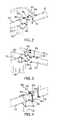
- FIG. 2is a perspective view from a first direction of a pair of sections separate apart according to one embodiment.
- FIG. 3is a perspective view from a second direction of a pair of sections separate apart according to one embodiment.
- FIG. 4is a perspective view of a pair of sections connected together according to one embodiment.
- FIG. 5Ais a schematic end view of a torque tube and solar cell modules at a first time of a day according to one embodiment.
- FIG. 5Bis a side view of the torque tube and solar cell modules of FIG. 2A .
- FIG. 6is a schematic end view of a torque tube and solar cell modules at a second time of the day according to one embodiment.
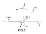
- FIG. 7is a schematic end view of a torque tube and solar cell modules at a third time of the day according to one embodiment.
- FIG. 8is a schematic end view of a torque tube and solar cell modules at a fourth time of the day according to one embodiment.
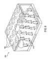
- FIG. 9is a perspective cut-away view of a solar cell array module according to one embodiment.
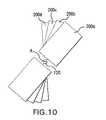
- FIG. 10is an end view of a torque tube and solar cell modules according to one embodiment.
- FIG. 1illustrates an embodiment of an array generally illustrated as element 100 .
- the array 100includes an elongated torque tube 120 configured to mount solar cell modules 200 in a longitudinally-extending and spaced-apart arrangement.
- a drive 170is connected to the torque tube 120 to rotate the solar cell modules 200 about a first axis A for the solar cell modules 200 to track the elevation of the sun during the course of a day.
- the torque tube 120is positioned above a surface 300 by spaced-apart vertical supports 130 .
- the torque tube 120is a single continuous piece.
- the torque tube 120is a pipe with a diameter of about 4-5.63 inches and includes a thickness of about 0.167-0.188 inches.
- the pipehas a length of about 170′′ and weighs about 110 lbs.
- the torque tube 120may also be constructed from a number of discrete sections 121 that are connected together in an end-to-end arrangement. The lengths and construction of each section 121 may be the same or may be different. In one embodiment, each section 121 is sized to mount a pair or multiple pairs of solar cell array modules 200 .
- the modular designprovides for a user to construct the torque tube 120 to a length needed to support a necessary number of solar cell modules 200 .
- Sections 121may be added to an existing frame 110 to accommodate additional solar cell modules 200 as is necessary for the array 100 to produce the desired power output.
- the torque tube 120may be constructed from various materials and combinations.
- the torque tube 120may be hollow, or may be solid. In the solid embodiments, the torque tube 120 may be constructed as a single, unitary construction, or may include a first exterior material, and one or more different interior materials.
- the sections 121may be configured to securely connect together as illustrated in FIGS. 2 , 3 , and 4 .
- Flanges 190may be positioned at the ends of the sections 121 and include corresponding surfaces that abut together.
- the flanges 190may be larger than the sections 121 with the outer edges of the flanges 190 extending outward beyond the sections 121 .
- FIGS. 2-4include the flanges 190 extending outward around the sections 121 , although flanges 190 may also be shaped and sized to extend outward from a limited area of the sections 121 .
- Apertures 191may extend through the flanges 190 to receive fasteners 193 to connect the sections 121 together. The apertures 191 are preferably positioned away from the sections 121 to allow access to the fasteners 193 .
- a centering pin 192may extend outward from the sections 121 and fit within an aperture 191 in an abutting flange 190 .
- the centering pin 192 and corresponding aperture 191are positioned along the longitudinal axis A and facilitate alignment of the different sections 121 .
- a torsion deflection adjustment mechanism 196may be connected to the sections 121 .
- the mechanism 196may include plates 195 that abut together and are connected with a fastener 193 .
- the enlarged contact area of the plates 195reduces torsional deflection during rotation of the torque tube 120 .
- the drive 170is connected to the torque tube 120 to provide a force to rotate the torque tube 120 about the longitudinal axis A.
- the drive 170is positioned within an intermediate point along the torque tube 120 .
- the drive 170is positioned at the center of the torque tube 120 and between discrete sections 121 .
- Other embodimentsmay include the drive 170 positioned at an end of the torque tube 120 or various other locations along the length.
- the drive 170may include a drive train with one or more gears that engage with the torque tube 120 . Additional drives 170 may be connected along the length of the torque tube 120 to provide additional rotational force.
- the torque tube 120When mounted on the surface 300 , the torque tube 120 may be positioned in a north N-south S orientation as illustrated in FIG. 1 .
- the surface 300is the surface of the Earth.
- the drive 170rotates the torque tube 120 to maintain the solar cell modules 200 facing towards the sun.
- the torque applied by the drive 170may cause the torque tube 120 to twist.
- the twistingdistorts the torque tube 120 causing the different modules 200 spaced along the length to rotate different amount. This variation in rotation may cause one or more of the modules 200 to be out of alignment with the sun.
- the amount of twist distortionincreases over the length of the torque tube 120 . Therefore, the amount of twisting distortion of the torque tube 120 in proximity to the drive 170 is smaller than the amount of twisting at a point farther away from the drive 170 .
- FIG. 5Aillustrates a schematic end view of the torque tube 120 that rotates about the longitudinal axis A in the direction of arrow C during the course of the day.
- FIG. 5Bis a schematic side view of the torque tube 120 and modules 200 .
- the drive 170is operatively connected to and rotates the torque tube 120 .
- a reference line Rextends through and is perpendicular to the longitudinal axis A. In one embodiment, the reference R is parallel to the surface 300 .
- module 200 ais positioned along the torque tube 120 a distance S that is closest to the drive 170 .
- Module 200 bis positioned a distance T which is second closest, module 200 c positioned a distance U a third distance, and module 200 d a distance V which is the farthest from the drive 170 .
- FIG. 5Aillustrates an initial position of the modules 200 with response to the torque tube 120 at a time with the drive 170 applying no rotational force to the torque tube 120 .
- the first module 200 ais positioned at a first angle ⁇ 1 with the module aligned in a first plane, module 200 b at a second angle ⁇ 2 and aligned in different second plane, module 200 c at a third angle ⁇ 3 and in a third plane, and module 200 d at a fourth angle ⁇ 4 and aligned in a fourth plane.
- the size of the angle ⁇is dependent upon the distance along the longitudinal axis A the module 200 is away from the drive 170 . The farther the module is located away from the drive 170 , the smaller the angle ⁇ . This relationship results because the amount of deformation increases along the length and results in less rotation of the modules 200 . In essence, the modules 200 in closer proximity to the drive 170 will rotate over a greater sweep range than the modules 200 positioned a greater distance away.
- the first module 200 a located in closer proximity to the drive 170is positioned at a lesser angle than the third module 200 c . The first module 200 a will rotate over a greater sweep during the course of the day than the third module 200 c.
- the sections 121may include the same or different materials, cross-sectional shape, size, and thickness.
- the different constructions and/or the connections between the discrete sections 121may affect the size of the offset angle ⁇ .
- FIGS. 5A-8illustrate the movement of the torque tube 120 and modules 200 a - 200 d during a course of the day as they rotate in the direction indicated by arrow C.
- FIGS. 5A and 5Binclude an initial position of the array 100 prior to the drive 170 applying rotational force to the torque tube 120 .
- the modules 200 a - dare offset at different rotational positions based on their distance away from the drive 170 . At this initial position, each of the modules 200 is aligned in a different plane.
- FIG. 6illustrates the array 100 at a later time during the day after the drive 170 has rotated the torque tube 120 an amount in the direction of arrow C.
- the rotationcauses the modules 200 a - d to remain aligned with the sun. Because of the deformation of the torque tube 120 , the different modules 200 a - d have experienced different amounts of rotation.
- Module 200 ais the closest to the drive 170 and has moved through the greatest rotational sweep.
- Module 200 bis the second closest to the drive 170 and has moved through the second greatest amount of rotation.
- the amounts of rotation of the third and fourth modules 200 c , 200 dis progressively less.
- the modules 200are each aligned in a different plane.
- FIG. 7illustrates the array 100 at a still later time during the day.
- the drive 170has rotated the torque tube 120 such that each of the modules 200 a - d are substantially aligned in a single plane. In one embodiment, this alignment occurs at the peak sun intensity of the day. In one embodiment, a section of the torque tube 120 at the drive rotates through an angular range of about 90 degrees from the initial starting position to the rotational point where the solar cell modules 200 are aligned in a common plane.
- FIG. 8illustrates a later time than that of FIG. 7 .
- the drive 170has continued to rotate the torque tube 120 .
- the first module 200 ahas rotated an amount to now lead the other modules 200 b - 200 d . This is the opposite of the relative position of first module 200 a which trailed the other modules 200 b - d prior to the peak time illustrated in FIG. 7 .
- the drive 170rotates the torque tube 120 with the other modules 200 b - 200 d rotating a less amount than module 200 a .
- the modules 200are again each aligned in a different plane at this time.
- the embodiment of FIG. 7includes a particular time at which each of the modules 200 are aligned in the same plane. Other embodiments may include no time at which each of the modules 200 are aligned in a common plane. Two or more of the modules 200 may be aligned at various times during the day.
- FIG. 9illustrates one embodiment of a solar cell module 200 .
- the solar cell modules 200are each about 43′′ by 67′′.
- FIG. 9illustrates an embodiment of a solar cell module 200 with an aluminum frame and plastic or corrugated plastic sides that reduce the overall weight to about 70 pounds.
- each solar cell module 200includes a 3 ⁇ 5 array of lenses 400 that are positioned over corresponding receivers 410 .
- the lensesmay include various shapes and sizes with one specific embodiment including lenses that are about 13′′ square. Further, the focal length between the lenses 400 and the receivers 410 is about 20′′.
- Each receiver 410may include one or more III-V compound semiconductor solar cells.
- the drive 170rotates the torque tube in a first direction during the course of the day. Prior to the start of the next day, the drive rotates the torque tube 120 in the opposite direction. The rotation in the second direction prepares the array 100 for tracking the elevation of the sun during the following day. In one embodiment, the drive 170 takes only a short period of time (e.g., several minutes) to rotate the array in the second direction from the ending point to the starting point.
- a short period of timee.g., several minutes
- the modules 200may be positioned at various spacings along the length of the torque tube 120 .
- FIG. 1includes the modules 200 aligned along the torque tube 120 in offsetting pairs on opposing sides of the torque tube 120 directly across from one another.
- Other offset positioningmay include the modules 200 unevenly spread along the length of the torque tube 120 with equal numbers extending outward from each opposing side. The offset positioning assists to balance the array 100 and facilitate rotation about the first axis A.
- Other configurationsmay include uneven numbers of modules 200 extending outward from the opposing sides of the torque tube 120 .
- FIGS. 5A-8include single modules 200 spaced along the longitudinal length of the torque tube 120 and each extending outward in substantially the same direction.
- FIG. 9includes paired modules 200 a - d with modules on opposing sides of the torque tube 120 .
- the modules 200are arranged in sets of four along the length of the length of the torque tube 120 .
- the setsmay be spaced apart along the length.
- a vertical support 130may also be positioned between adjacent sets.
- Each of the modules 200 within a setmay be positioned at the same angular offset.
- the first set of modules 200 immediately to the right of the drive 170are each offset at a first angular position.
- the next set of four modules that are spaced away from the first setmay each be oriented at a different angular offset.
- the vertical supports 130are spaced apart along the length of the torque tube 120 .
- the vertical supports 130include a length adequate to position the solar cell modules 120 above the surface 300 for rotation about the first axis A. Therefore, the vertical supports 130 are longer than a height of the solar cell modules 200 .
- the vertical supports 130include a 4 inch by 4 inch rectangular shape, and include a thickness of about 0.188 inches.
- the vertical supports 130may also be supported in a concrete pad.
- the modules 200may also be connected to the torque tube to rotate along axes B that are substantially perpendicular to axis A to track the azimuthal position of the sun during the course of the day.
- the shadow cast by a given solar cell module 200depends on its size and shape, and also on its location relative to the location of the sun in the sky. In the East-West direction, the sun location can vary by up to 150°. In this connection, it should be noted that it is generally accepted that, where the elevation of the sun is below 15° above the horizon, its rays are of insufficient strength to generate a useful amount of electricity. The latitude at which the solar cell array 100 is positioned is, therefore, of little influence.
- the solar cell array 100is constructed in a manner to eliminate or minimize shadowing problems between solar cell modules 200 .
- the torque tube 120 and the individual sections 121 of the solar cell modules 200are sized to space apart each module 200 such that it is fully illuminated for positions where the sun is 15° above the horizon, and that there is no shadowing of any given module 200 by any other module 200 .
- the terrestrial solar tracking array 100can be installed in a straight-forward manner.
- the various componentsare sized to fit within a standard vehicle and are light-weight to allow installation by a single person or limited number of persons.
- the modular aspect of the array 100facilitates modifications after the initial installation. Additional sections 121 and vertical supports 130 may be added to the frame 110 to accommodate a desired number of additional solar cell modules 200 . The distance the added modules 200 will be spaced away from the drive 170 is calculated and the appropriate angular offset is determined for positioned the modules 200 relative to the torque tube 120 . Further, the size of the array 100 may be reduced after installation by removing one or more solar cell modules 200 .
Landscapes
- Engineering & Computer Science (AREA)
- Life Sciences & Earth Sciences (AREA)
- Sustainable Development (AREA)
- Physics & Mathematics (AREA)
- Sustainable Energy (AREA)
- Thermal Sciences (AREA)
- Chemical & Material Sciences (AREA)
- Combustion & Propulsion (AREA)
- Mechanical Engineering (AREA)
- General Engineering & Computer Science (AREA)
- Photovoltaic Devices (AREA)
Abstract
Description
Claims (22)
Priority Applications (2)
| Application Number | Priority Date | Filing Date | Title |
|---|---|---|---|
| US12/623,134US8378281B2 (en) | 2008-10-24 | 2009-11-20 | Terrestrial solar tracking photovoltaic array with offset solar cell modules |
| US13/770,805US8686334B2 (en) | 2008-10-24 | 2013-02-19 | Terrestrial solar tracking photovoltaic array with offset solar cell modules |
Applications Claiming Priority (4)
| Application Number | Priority Date | Filing Date | Title |
|---|---|---|---|
| US12/257,670US8188413B2 (en) | 2008-10-24 | 2008-10-24 | Terrestrial concentrator solar tracking photovoltaic array |
| US12/478,567US8188415B2 (en) | 2008-10-24 | 2009-06-04 | Terrestrial solar tracking photovoltaic array |
| US12/574,508US20100101630A1 (en) | 2008-10-24 | 2009-10-06 | Terrestrial Solar Tracking Photovoltaic Array with Slew Speed Reducer |
| US12/623,134US8378281B2 (en) | 2008-10-24 | 2009-11-20 | Terrestrial solar tracking photovoltaic array with offset solar cell modules |
Related Parent Applications (1)
| Application Number | Title | Priority Date | Filing Date |
|---|---|---|---|
| US12/574,508Continuation-In-PartUS20100101630A1 (en) | 2008-10-24 | 2009-10-06 | Terrestrial Solar Tracking Photovoltaic Array with Slew Speed Reducer |
Related Child Applications (1)
| Application Number | Title | Priority Date | Filing Date |
|---|---|---|---|
| US13/770,805ContinuationUS8686334B2 (en) | 2008-10-24 | 2013-02-19 | Terrestrial solar tracking photovoltaic array with offset solar cell modules |
Publications (2)
| Publication Number | Publication Date |
|---|---|
| US20100101632A1 US20100101632A1 (en) | 2010-04-29 |
| US8378281B2true US8378281B2 (en) | 2013-02-19 |
Family
ID=42116314
Family Applications (2)
| Application Number | Title | Priority Date | Filing Date |
|---|---|---|---|
| US12/623,134Expired - Fee RelatedUS8378281B2 (en) | 2008-10-24 | 2009-11-20 | Terrestrial solar tracking photovoltaic array with offset solar cell modules |
| US13/770,805Expired - Fee RelatedUS8686334B2 (en) | 2008-10-24 | 2013-02-19 | Terrestrial solar tracking photovoltaic array with offset solar cell modules |
Family Applications After (1)
| Application Number | Title | Priority Date | Filing Date |
|---|---|---|---|
| US13/770,805Expired - Fee RelatedUS8686334B2 (en) | 2008-10-24 | 2013-02-19 | Terrestrial solar tracking photovoltaic array with offset solar cell modules |
Country Status (1)
| Country | Link |
|---|---|
| US (2) | US8378281B2 (en) |
Cited By (11)
| Publication number | Priority date | Publication date | Assignee | Title |
|---|---|---|---|---|
| US20100101630A1 (en)* | 2008-10-24 | 2010-04-29 | Emcore Solar Power, Inc. | Terrestrial Solar Tracking Photovoltaic Array with Slew Speed Reducer |
| US8536504B2 (en) | 2008-10-24 | 2013-09-17 | Suncore Photovoltaics, Inc. | Terrestrial solar tracking photovoltaic array with chain drive |
| US8686334B2 (en) | 2008-10-24 | 2014-04-01 | Suncore Photovoltaics, Inc. | Terrestrial solar tracking photovoltaic array with offset solar cell modules |
| US8778199B2 (en) | 2009-02-09 | 2014-07-15 | Emoore Solar Power, Inc. | Epitaxial lift off in inverted metamorphic multijunction solar cells |
| US8895342B2 (en) | 2007-09-24 | 2014-11-25 | Emcore Solar Power, Inc. | Heterojunction subcells in inverted metamorphic multijunction solar cells |
| WO2015034862A1 (en)* | 2013-09-04 | 2015-03-12 | COMBINED POWER LLC, dba HYPERLIGHT ENERGY | Systems and methods of generating energy from solar radiation |
| US20150082941A1 (en)* | 2013-09-26 | 2015-03-26 | Brent Morgan | Slew drive gearbox with spherical adjusting mount |
| US9018519B1 (en) | 2009-03-10 | 2015-04-28 | Solaero Technologies Corp. | Inverted metamorphic multijunction solar cells having a permanent supporting substrate |
| US9287438B1 (en) | 2008-07-16 | 2016-03-15 | Solaero Technologies Corp. | Method for forming ohmic N-contacts at low temperature in inverted metamorphic multijunction solar cells with contaminant isolation |
| US10541349B1 (en) | 2008-12-17 | 2020-01-21 | Solaero Technologies Corp. | Methods of forming inverted multijunction solar cells with distributed Bragg reflector |
| US10931224B2 (en) | 2016-06-03 | 2021-02-23 | RBI Solar, Inc. | Single axis in-line gearbox modular tracker system |
Families Citing this family (30)
| Publication number | Priority date | Publication date | Assignee | Title |
|---|---|---|---|---|
| US9634172B1 (en) | 2007-09-24 | 2017-04-25 | Solaero Technologies Corp. | Inverted metamorphic multijunction solar cell with multiple metamorphic layers |
| US9117966B2 (en) | 2007-09-24 | 2015-08-25 | Solaero Technologies Corp. | Inverted metamorphic multijunction solar cell with two metamorphic layers and homojunction top cell |
| US10381501B2 (en) | 2006-06-02 | 2019-08-13 | Solaero Technologies Corp. | Inverted metamorphic multijunction solar cell with multiple metamorphic layers |
| US10381505B2 (en) | 2007-09-24 | 2019-08-13 | Solaero Technologies Corp. | Inverted metamorphic multijunction solar cells including metamorphic layers |
| US8513514B2 (en) | 2008-10-24 | 2013-08-20 | Suncore Photovoltaics, Inc. | Solar tracking for terrestrial solar arrays with variable start and stop positions |
| US8188415B2 (en)* | 2008-10-24 | 2012-05-29 | Emcore Solar Power, Inc. | Terrestrial solar tracking photovoltaic array |
| US8507837B2 (en) | 2008-10-24 | 2013-08-13 | Suncore Photovoltaics, Inc. | Techniques for monitoring solar array performance and applications thereof |
| US8188413B2 (en)* | 2008-10-24 | 2012-05-29 | Emcore Solar Power, Inc. | Terrestrial concentrator solar tracking photovoltaic array |
| US8466399B1 (en) | 2008-10-24 | 2013-06-18 | Suncore Photovoltaics, Inc. | Techniques for adjusting solar array tracking |
| US8453328B2 (en) | 2010-06-01 | 2013-06-04 | Suncore Photovoltaics, Inc. | Methods and devices for assembling a terrestrial solar tracking photovoltaic array |
| US8592738B1 (en) | 2010-07-01 | 2013-11-26 | Suncore Photovoltaics, Inc. | Alignment device for use with a solar tracking photovoltaic array |
| IT1400713B1 (en)* | 2010-07-05 | 2013-06-28 | Emcore Solar Power Inc | METHODS AND DEVICES FOR ASSEMBLING A TERRESTRIAL PHOTOVOLTAIC GROUP FOR SOLAR TRACKING. |
| US8407950B2 (en) | 2011-01-21 | 2013-04-02 | First Solar, Inc. | Photovoltaic module support system |
| US20120318323A1 (en)* | 2011-02-14 | 2012-12-20 | Paul Anthony Tomaso | Ground mount ballast solar racking system |
| DE112013003631T5 (en)* | 2012-07-23 | 2015-04-09 | Magna International Inc. | Single-axis sun tracking arrangement |
| US9766319B2 (en) | 2012-12-10 | 2017-09-19 | Nextracker Inc. | Off-set drive assembly for solar tracker |
| US10008975B2 (en) | 2012-12-10 | 2018-06-26 | Nextracker Inc. | Clamp assembly for solar tracker |
| US9466749B1 (en)* | 2012-12-10 | 2016-10-11 | Nextracker Inc. | Balanced solar tracker clamp |
| JP2016504901A (en) | 2012-12-10 | 2016-02-12 | ネクストラッカー インコーポレイテッドNEXTracker Inc. | Horizontal balance solar tracking device |
| WO2015051267A1 (en)* | 2013-10-05 | 2015-04-09 | Magna International Inc. | Solar photovoltaic single axis tracker |
| CN103731089B (en)* | 2013-12-31 | 2016-03-16 | 天津蓝天太阳科技有限公司 | A kind of roof type solar power generation array tracing system |
| WO2015113445A1 (en)* | 2014-01-30 | 2015-08-06 | 浙江同景新能源集团有限公司 | Improved photovoltaic tracking and control system |
| CN205453610U (en) | 2014-09-17 | 2016-08-10 | 耐克斯特拉克尔有限公司 | Solar energy tracking device |
| CN105906815B (en)* | 2016-06-27 | 2018-11-23 | 大连民族大学 | Microenvironment double-response chitosan gene vector and its preparation method and application |
| US10305418B2 (en) | 2016-09-01 | 2019-05-28 | Sunpower Corporation | Torque tube coupler |
| EP3507902B1 (en)* | 2016-09-01 | 2021-11-24 | SunPower Corporation | Torque tube coupler |
| CN107280403A (en)* | 2017-08-02 | 2017-10-24 | 佛山科学技术学院 | A kind of tableware with heat insulation function |
| CN108807601B (en)* | 2018-07-16 | 2023-08-25 | 苏州迈为科技股份有限公司 | Battery piece splitting device, full-automatic splitting machine and splitting method |
| USD905626S1 (en) | 2019-07-25 | 2020-12-22 | Nextracker Inc. | Panel rail saddle for solar module |
| CN116149381B (en)* | 2022-10-28 | 2024-10-29 | 天合光能股份有限公司 | Tracking bracket connecting rod design method and device based on generating capacity loss optimization |
Citations (61)
| Publication number | Priority date | Publication date | Assignee | Title |
|---|---|---|---|---|
| US4031385A (en) | 1976-04-05 | 1977-06-21 | Desert Sunshine Exposure Tests, Inc. | Solar tracking device |
| US4172739A (en) | 1977-12-27 | 1979-10-30 | Solar Homes, Inc. | Sun tracker with dual axis support for diurnal movement and seasonal adjustment |
| US4345582A (en) | 1979-11-19 | 1982-08-24 | Aharon Naaman B | System for the utilization of solar energy |
| US4425904A (en) | 1980-10-01 | 1984-01-17 | The United States Of America As Represented By The United States Department Of Energy | Tracking system for solar collectors |
| US4440465A (en) | 1981-04-06 | 1984-04-03 | Elliott James M | Electrical plug connector lock |
| US4585318A (en) | 1983-01-14 | 1986-04-29 | Dieter Seifert | Tracking device |
| US4586488A (en) | 1983-12-15 | 1986-05-06 | Noto Vincent H | Reflective solar tracking system |
| US4628142A (en) | 1984-03-19 | 1986-12-09 | Kabushiki Kaisha Toshiba | Solar tracking mechanisms |
| US4832001A (en) | 1987-05-28 | 1989-05-23 | Zomeworks Corporation | Lightweight solar panel support |
| US4888340A (en) | 1985-12-21 | 1989-12-19 | Schering Aktiengesellschaft | Insecticides pyrazolines, compositions and use |
| US4989124A (en) | 1989-08-21 | 1991-01-29 | Shappell Thomas E | Solar powered sign |
| US4995377A (en) | 1990-06-29 | 1991-02-26 | Eiden Glenn E | Dual axis solar collector assembly |
| US5169456A (en) | 1991-10-22 | 1992-12-08 | Johnson Kenneth C | Two-axis tracking solar collector mechanism |
| US5600124A (en) | 1991-12-03 | 1997-02-04 | Berger; Alexander | Sun tracker system for a solar assembly |
| US5798517A (en) | 1994-05-19 | 1998-08-25 | Berger; Alexander | Sun tracker system for a solar assembly |
| US6058930A (en) | 1999-04-21 | 2000-05-09 | Shingleton; Jefferson | Solar collector and tracker arrangement |
| US6079408A (en) | 1998-03-30 | 2000-06-27 | Honda Giken Kogyo Kabushiki Kaisha | Sun-ray tracking system |
| JP2000196127A (en) | 1998-12-25 | 2000-07-14 | Honda Motor Co Ltd | Fault diagnosing device and fault diagnosing method for concentrating tracking power generation system |
| JP2000223730A (en) | 1999-02-04 | 2000-08-11 | Honda Motor Co Ltd | Solar tracking type power generation system and operation method thereof |
| US6123067A (en) | 1999-03-31 | 2000-09-26 | Amonix, Inc. | Solar collector tracking system |
| WO2001055651A1 (en) | 2000-01-27 | 2001-08-02 | Haber Michael B | Solar panel tilt mechanism |
| JP2002202817A (en) | 2000-12-28 | 2002-07-19 | Rhythm Watch Co Ltd | Sun tracking system |
| WO2002079793A1 (en) | 2001-03-28 | 2002-10-10 | Solar Systems Pty Ltd | Solar tracking system |
| US6465725B1 (en) | 2000-01-31 | 2002-10-15 | Honda Giken Kogyo Kabushiki Kaisha | Tracking type photovoltaic power generator and error correction method of its built-in clock |
| US6552257B1 (en) | 2001-10-16 | 2003-04-22 | American Signal Company | Nonrotating pivotable solar panel |
| US6563040B2 (en) | 2001-10-11 | 2003-05-13 | Pinnacle West Capital Corporation | Structure for supporting a photovoltaic module in a solar energy collection system |
| US6722357B2 (en) | 2001-08-15 | 2004-04-20 | Powerlight Corporation | Fixed angle solar collector arrangement |
| US20040112373A1 (en) | 2002-12-09 | 2004-06-17 | Derek Djeu | Passive Solar Tracker for a Solar Concentrator |
| DE102004018151A1 (en) | 2004-04-08 | 2005-10-27 | Neff, Siegfried | Solar modules adjusting device for use in house, has power transmission linkages connected with solar modules and cooperating with connecting links, such that it drives solar modules when links are driven by drive motors |
| DE202006003476U1 (en) | 2006-02-28 | 2006-12-28 | Conergy Ag | Tracking frame system for solar modules, especially photovoltaic modules, comprises a support frame rotating between two feet and coupled via a pivoting rod with a linear sliding bearing and an electric cylinder |
| ES2268938A1 (en) | 2004-09-27 | 2007-03-16 | Fernando Garcia Fraile | Multi-directional solar platform has counterbalances to neutralize effects of eastern/western wind impacts acting on solar panel receptacle rotationally supported on main shaft |
| US20070089777A1 (en) | 2005-10-04 | 2007-04-26 | Johnson Richard L Jr | Heatsink for concentrating or focusing optical/electrical energy conversion systems |
| US20070101738A1 (en) | 2005-11-09 | 2007-05-10 | Masao Akei | Vapor compression circuit and method including a thermoelectric device |
| US7252084B2 (en) | 2004-06-28 | 2007-08-07 | Lucent Technologies Inc. | Solar tracking system |
| US20070188876A1 (en) | 2006-01-17 | 2007-08-16 | Hines Braden E | Hybrid primary optical component for optical concentrators |
| US20070193620A1 (en) | 2006-01-17 | 2007-08-23 | Hines Braden E | Concentrating solar panel and related systems and methods |
| WO2008008023A1 (en) | 2006-07-13 | 2008-01-17 | Karim Ibrahim Najar | Solar collector |
| US7381886B1 (en) | 2007-07-30 | 2008-06-03 | Emcore Corporation | Terrestrial solar array |
| US20080128586A1 (en) | 2006-10-13 | 2008-06-05 | Johnson Richard L | Sun sensor assembly and related method of using |
| US20080135087A1 (en) | 2007-05-10 | 2008-06-12 | Rangappan Anikara | Thin solar concentrator |
| WO2008090241A1 (en) | 2007-01-23 | 2008-07-31 | Energia Ercam, S.A. | Two-axis solar tracker |
| US20080178867A1 (en) | 2007-01-30 | 2008-07-31 | Xtreme Energetics Inc | Solid-state sun tracker |
| US20080236567A1 (en) | 2007-03-29 | 2008-10-02 | Hayden Herbert T | System for supporting energy conversion modules |
| US20080258051A1 (en) | 2007-04-11 | 2008-10-23 | Solfocus, Inc. | Equipment and Process for Measuring the Precision of Sun Tracking for Photovoltaic Concentrators |
| WO2008154945A1 (en) | 2007-06-21 | 2008-12-24 | Conergy Ag | Modular pivotable solar collector arrangement |
| US20090000662A1 (en) | 2007-03-11 | 2009-01-01 | Harwood Duncan W J | Photovoltaic receiver for solar concentrator applications |
| US20090032090A1 (en) | 2007-07-30 | 2009-02-05 | Emcore Corporation | Method for assembling a terrestrial solar array including a rigid support frame |
| US20090032014A1 (en) | 2007-07-31 | 2009-02-05 | Yevgeny Meydbray | Variable tilt tracker for photovoltaic arrays |
| WO2009048879A2 (en) | 2007-10-12 | 2009-04-16 | Megawatt Solar, Inc. | Methods, systems, and computer readable media for controlling orientation of a photovoltaic collection system to track apparent movement of the sun |
| US7531741B1 (en)* | 2003-03-07 | 2009-05-12 | Sacred Power Corporation | Tracking solar shelter |
| US20090199890A1 (en)* | 2008-02-11 | 2009-08-13 | Emcore Corporation | Solar cell receiver for concentrated photovoltaic system for III-V semiconductor solar cell |
| US20100011565A1 (en) | 2008-07-21 | 2010-01-21 | Emcore Corporation | Methods of forming a lens sheet for a photovoltaic solar cell system |
| US20100018570A1 (en) | 2008-05-16 | 2010-01-28 | Cashion Steven A | Concentrating photovoltaic solar panel |
| US20100102200A1 (en) | 2008-10-24 | 2010-04-29 | Emcore Solar Power, Inc. | Terrestrial Solar Tracking Photovoltaic Array |
| US20100102202A1 (en) | 2008-10-24 | 2010-04-29 | Emcore Solar Power, Inc, | Solar Tracking for Terrestrial Solar Arrays with Variable Start and Stop Positions |
| US20100101630A1 (en) | 2008-10-24 | 2010-04-29 | Emcore Solar Power, Inc. | Terrestrial Solar Tracking Photovoltaic Array with Slew Speed Reducer |
| US20100101625A1 (en) | 2008-10-24 | 2010-04-29 | Emcore Solar Power, Inc. | Terrestrial Solar Tracking Photovoltaic Array |
| US20100108860A1 (en) | 2008-10-24 | 2010-05-06 | Emcore Solar Power, Inc. | Techniques for Monitoring Solar Array Performance and Applications Thereof |
| US7795568B2 (en) | 2008-10-24 | 2010-09-14 | Emcore Solar Power, Inc. | Solar tracking for terrestrial solar arrays |
| US7836879B2 (en)* | 2004-08-10 | 2010-11-23 | Kevin Keith Mackamul | Tracker drive system and solar energy collection system |
| US20100294337A1 (en) | 2009-05-19 | 2010-11-25 | Emcore Solar Power, Inc. | Periodic Alignment Adjustment Techniques for Terrestrial Solar Arrays |
Family Cites Families (11)
| Publication number | Priority date | Publication date | Assignee | Title |
|---|---|---|---|---|
| US4133501A (en) | 1975-09-30 | 1979-01-09 | Communications Satellite Corporation | Self-deployable solar cell panel |
| US4429178A (en)* | 1981-07-13 | 1984-01-31 | Acurex Solar Corporation | Solar tracking apparatus utilizing photovoltaic flat panels and method |
| US6005236A (en) | 1995-10-02 | 1999-12-21 | Phelan; John J. | Automatic sun tracking apparatus |
| JPH1013635A (en)* | 1996-06-20 | 1998-01-16 | Brother Ind Ltd | Image reading device |
| US20080029151A1 (en) | 2006-08-07 | 2008-02-07 | Mcglynn Daniel | Terrestrial solar power system using III-V semiconductor solar cells |
| US7381866B1 (en) | 2007-01-18 | 2008-06-03 | Monsanto Technology Llc | Soybean variety 4958786 |
| US8536504B2 (en) | 2008-10-24 | 2013-09-17 | Suncore Photovoltaics, Inc. | Terrestrial solar tracking photovoltaic array with chain drive |
| US8378281B2 (en) | 2008-10-24 | 2013-02-19 | Suncore Photovoltaics, Inc. | Terrestrial solar tracking photovoltaic array with offset solar cell modules |
| US8466399B1 (en) | 2008-10-24 | 2013-06-18 | Suncore Photovoltaics, Inc. | Techniques for adjusting solar array tracking |
| US7968791B2 (en) | 2009-07-30 | 2011-06-28 | Skyline Solar, Inc. | Solar energy collection system |
| US8453328B2 (en) | 2010-06-01 | 2013-06-04 | Suncore Photovoltaics, Inc. | Methods and devices for assembling a terrestrial solar tracking photovoltaic array |
- 2009
- 2009-11-20USUS12/623,134patent/US8378281B2/ennot_activeExpired - Fee Related
- 2013
- 2013-02-19USUS13/770,805patent/US8686334B2/ennot_activeExpired - Fee Related
Patent Citations (66)
| Publication number | Priority date | Publication date | Assignee | Title |
|---|---|---|---|---|
| US4031385A (en) | 1976-04-05 | 1977-06-21 | Desert Sunshine Exposure Tests, Inc. | Solar tracking device |
| US4172739A (en) | 1977-12-27 | 1979-10-30 | Solar Homes, Inc. | Sun tracker with dual axis support for diurnal movement and seasonal adjustment |
| US4345582A (en) | 1979-11-19 | 1982-08-24 | Aharon Naaman B | System for the utilization of solar energy |
| US4425904A (en) | 1980-10-01 | 1984-01-17 | The United States Of America As Represented By The United States Department Of Energy | Tracking system for solar collectors |
| US4440465A (en) | 1981-04-06 | 1984-04-03 | Elliott James M | Electrical plug connector lock |
| US4585318A (en) | 1983-01-14 | 1986-04-29 | Dieter Seifert | Tracking device |
| US4586488A (en) | 1983-12-15 | 1986-05-06 | Noto Vincent H | Reflective solar tracking system |
| US4628142A (en) | 1984-03-19 | 1986-12-09 | Kabushiki Kaisha Toshiba | Solar tracking mechanisms |
| US4888340A (en) | 1985-12-21 | 1989-12-19 | Schering Aktiengesellschaft | Insecticides pyrazolines, compositions and use |
| US4832001A (en) | 1987-05-28 | 1989-05-23 | Zomeworks Corporation | Lightweight solar panel support |
| US4989124A (en) | 1989-08-21 | 1991-01-29 | Shappell Thomas E | Solar powered sign |
| US4995377A (en) | 1990-06-29 | 1991-02-26 | Eiden Glenn E | Dual axis solar collector assembly |
| US5169456A (en) | 1991-10-22 | 1992-12-08 | Johnson Kenneth C | Two-axis tracking solar collector mechanism |
| US5600124A (en) | 1991-12-03 | 1997-02-04 | Berger; Alexander | Sun tracker system for a solar assembly |
| US5798517A (en) | 1994-05-19 | 1998-08-25 | Berger; Alexander | Sun tracker system for a solar assembly |
| US6079408A (en) | 1998-03-30 | 2000-06-27 | Honda Giken Kogyo Kabushiki Kaisha | Sun-ray tracking system |
| JP2000196127A (en) | 1998-12-25 | 2000-07-14 | Honda Motor Co Ltd | Fault diagnosing device and fault diagnosing method for concentrating tracking power generation system |
| JP2000223730A (en) | 1999-02-04 | 2000-08-11 | Honda Motor Co Ltd | Solar tracking type power generation system and operation method thereof |
| US6123067A (en) | 1999-03-31 | 2000-09-26 | Amonix, Inc. | Solar collector tracking system |
| US6058930A (en) | 1999-04-21 | 2000-05-09 | Shingleton; Jefferson | Solar collector and tracker arrangement |
| WO2001055651A1 (en) | 2000-01-27 | 2001-08-02 | Haber Michael B | Solar panel tilt mechanism |
| US6465725B1 (en) | 2000-01-31 | 2002-10-15 | Honda Giken Kogyo Kabushiki Kaisha | Tracking type photovoltaic power generator and error correction method of its built-in clock |
| JP2002202817A (en) | 2000-12-28 | 2002-07-19 | Rhythm Watch Co Ltd | Sun tracking system |
| WO2002079793A1 (en) | 2001-03-28 | 2002-10-10 | Solar Systems Pty Ltd | Solar tracking system |
| US6722357B2 (en) | 2001-08-15 | 2004-04-20 | Powerlight Corporation | Fixed angle solar collector arrangement |
| US6563040B2 (en) | 2001-10-11 | 2003-05-13 | Pinnacle West Capital Corporation | Structure for supporting a photovoltaic module in a solar energy collection system |
| US6552257B1 (en) | 2001-10-16 | 2003-04-22 | American Signal Company | Nonrotating pivotable solar panel |
| US6960717B2 (en) | 2001-10-16 | 2005-11-01 | American Signal Company | Adjustable solar panel |
| US20040112373A1 (en) | 2002-12-09 | 2004-06-17 | Derek Djeu | Passive Solar Tracker for a Solar Concentrator |
| US7531741B1 (en)* | 2003-03-07 | 2009-05-12 | Sacred Power Corporation | Tracking solar shelter |
| DE102004018151A1 (en) | 2004-04-08 | 2005-10-27 | Neff, Siegfried | Solar modules adjusting device for use in house, has power transmission linkages connected with solar modules and cooperating with connecting links, such that it drives solar modules when links are driven by drive motors |
| US7252084B2 (en) | 2004-06-28 | 2007-08-07 | Lucent Technologies Inc. | Solar tracking system |
| US7836879B2 (en)* | 2004-08-10 | 2010-11-23 | Kevin Keith Mackamul | Tracker drive system and solar energy collection system |
| ES2268938A1 (en) | 2004-09-27 | 2007-03-16 | Fernando Garcia Fraile | Multi-directional solar platform has counterbalances to neutralize effects of eastern/western wind impacts acting on solar panel receptacle rotationally supported on main shaft |
| US20070089777A1 (en) | 2005-10-04 | 2007-04-26 | Johnson Richard L Jr | Heatsink for concentrating or focusing optical/electrical energy conversion systems |
| US20070101738A1 (en) | 2005-11-09 | 2007-05-10 | Masao Akei | Vapor compression circuit and method including a thermoelectric device |
| US20070188876A1 (en) | 2006-01-17 | 2007-08-16 | Hines Braden E | Hybrid primary optical component for optical concentrators |
| US20070193620A1 (en) | 2006-01-17 | 2007-08-23 | Hines Braden E | Concentrating solar panel and related systems and methods |
| DE202006003476U1 (en) | 2006-02-28 | 2006-12-28 | Conergy Ag | Tracking frame system for solar modules, especially photovoltaic modules, comprises a support frame rotating between two feet and coupled via a pivoting rod with a linear sliding bearing and an electric cylinder |
| WO2008008023A1 (en) | 2006-07-13 | 2008-01-17 | Karim Ibrahim Najar | Solar collector |
| US20080128586A1 (en) | 2006-10-13 | 2008-06-05 | Johnson Richard L | Sun sensor assembly and related method of using |
| WO2008090241A1 (en) | 2007-01-23 | 2008-07-31 | Energia Ercam, S.A. | Two-axis solar tracker |
| US20080178867A1 (en) | 2007-01-30 | 2008-07-31 | Xtreme Energetics Inc | Solid-state sun tracker |
| US20090000662A1 (en) | 2007-03-11 | 2009-01-01 | Harwood Duncan W J | Photovoltaic receiver for solar concentrator applications |
| US20080236567A1 (en) | 2007-03-29 | 2008-10-02 | Hayden Herbert T | System for supporting energy conversion modules |
| US20080258051A1 (en) | 2007-04-11 | 2008-10-23 | Solfocus, Inc. | Equipment and Process for Measuring the Precision of Sun Tracking for Photovoltaic Concentrators |
| US20080135087A1 (en) | 2007-05-10 | 2008-06-12 | Rangappan Anikara | Thin solar concentrator |
| WO2008154945A1 (en) | 2007-06-21 | 2008-12-24 | Conergy Ag | Modular pivotable solar collector arrangement |
| US20100258110A1 (en) | 2007-06-21 | 2010-10-14 | Voltwerk Electronics Gmbh | Modular Pivotable Solar Collector Arrangement |
| US20090032090A1 (en) | 2007-07-30 | 2009-02-05 | Emcore Corporation | Method for assembling a terrestrial solar array including a rigid support frame |
| US20090032084A1 (en) | 2007-07-30 | 2009-02-05 | Emcore Corporation | Optimization of ground coverage of terrestrial solar array system |
| US20090032086A1 (en) | 2007-07-30 | 2009-02-05 | Emcore Corporation | Terrestrial solar array including a rigid support frame |
| US7381886B1 (en) | 2007-07-30 | 2008-06-03 | Emcore Corporation | Terrestrial solar array |
| US20090032014A1 (en) | 2007-07-31 | 2009-02-05 | Yevgeny Meydbray | Variable tilt tracker for photovoltaic arrays |
| WO2009048879A2 (en) | 2007-10-12 | 2009-04-16 | Megawatt Solar, Inc. | Methods, systems, and computer readable media for controlling orientation of a photovoltaic collection system to track apparent movement of the sun |
| US20090199890A1 (en)* | 2008-02-11 | 2009-08-13 | Emcore Corporation | Solar cell receiver for concentrated photovoltaic system for III-V semiconductor solar cell |
| US20100018570A1 (en) | 2008-05-16 | 2010-01-28 | Cashion Steven A | Concentrating photovoltaic solar panel |
| US20100032004A1 (en) | 2008-05-16 | 2010-02-11 | Baker James T | Solar systems that include one or more shade-tolerant wiring schemes |
| US20100011565A1 (en) | 2008-07-21 | 2010-01-21 | Emcore Corporation | Methods of forming a lens sheet for a photovoltaic solar cell system |
| US20100102202A1 (en) | 2008-10-24 | 2010-04-29 | Emcore Solar Power, Inc, | Solar Tracking for Terrestrial Solar Arrays with Variable Start and Stop Positions |
| US20100101625A1 (en) | 2008-10-24 | 2010-04-29 | Emcore Solar Power, Inc. | Terrestrial Solar Tracking Photovoltaic Array |
| US20100108860A1 (en) | 2008-10-24 | 2010-05-06 | Emcore Solar Power, Inc. | Techniques for Monitoring Solar Array Performance and Applications Thereof |
| US7795568B2 (en) | 2008-10-24 | 2010-09-14 | Emcore Solar Power, Inc. | Solar tracking for terrestrial solar arrays |
| US20100101630A1 (en) | 2008-10-24 | 2010-04-29 | Emcore Solar Power, Inc. | Terrestrial Solar Tracking Photovoltaic Array with Slew Speed Reducer |
| US20100102200A1 (en) | 2008-10-24 | 2010-04-29 | Emcore Solar Power, Inc. | Terrestrial Solar Tracking Photovoltaic Array |
| US20100294337A1 (en) | 2009-05-19 | 2010-11-25 | Emcore Solar Power, Inc. | Periodic Alignment Adjustment Techniques for Terrestrial Solar Arrays |
Non-Patent Citations (70)
| Title |
|---|
| "170 Watt Multi-Purpose Module NEC 2008 Compliant, NE-170UC1" datasheet. Sharp Electronics Corporation, Huntington, CA, 2008; 2 pgs. |
| "170 Watt NE-170UC1." Data Sheet, 2 pages. Sharp.co.jp. Sharp Electronics Corp., Huntington Beach, CA. |
| "Concentrating PV module and system developers#5" PHOTON International: The Photovoltaic Magazine, Photon Europe GmbH, Germany, Aug. 2009; pp. 134-137. |
| "Concentrating PV module and system developers." Photon International: The Photovoltaic Magazine. Aug. 2009. pp. 134-137. Photon Europe GmbH, Aachen, Germany. |
| "FEiNA SF-20 Dual Axis Tracker" datasheet. OPEL Solar(TM) Inc., www.opelinc.com, Shelton, CT, Nov. 2009; 2 pgs. |
| "FEiNA SF-20 Dual Axis Tracker" datasheet. OPEL Solar™ Inc., www.opelinc.com, Shelton, CT, Nov. 2009; 2 pgs. |
| "FEiNA SF-20 Dual Axis Tracker." Data Sheet, 2 pages. www.opelinc.com. OPEL Solar Inc. Shelton, CT. |
| "FEiNA SF-4 Mini Tracker" datasheet. OPEL Solar(TM) Inc., www.opelinc.com, Shelton, CT, Nov. 2009; 2 pgs. |
| "FEiNA SF-4 Mini Tracker" datasheet. OPEL Solar™ Inc., www.opelinc.com, Shelton, CT, Nov. 2009; 2 pgs. |
| "FEiNA SF-4 Mini Tracker." Data Sheet, 2 pages. www.opelinc.com. OPEL Solar Inc. Shelton, CT. |
| "FEiNA SF-9 Dual Axis Tracker" datasheet. OPEL Solar(TM) Inc., www.opelinc.com, Shelton, CT, Nov. 2009; 2 pgs. |
| "FEiNA SF-9 Dual Axis Tracker" datasheet. OPEL Solar™ Inc., www.opelinc.com, Shelton, CT, Nov. 2009; 2 pgs. |
| "FEiNA SF-9 Dual Axis Tracker." Data Sheet, 2 pages. www.opelinc.com. OPEL Solar Inc. Shelton, CT. |
| "GLOBO-welding, Laser welding of plastics-innovative and flexible. The universal processing concept for 3D and continuous applications," Brochure datasheet. http://www.leister.com/uploads/pdf/en/BRO-GLOBO-Welding-dv092006-Eng.pdf Leister Process Technologies, LLC, Sarnen, Switzerland, Sep. 2009; 4 pgs. |
| "GLOBO-welding. Laser welding of plastics-innovative and flexible. The universal processing concept for 3D and continuous applications." Brochure. http://www.leister.com/uploads/pdf/en/BRO-GLOBO-Welding-dv092006-ENG.pdf. Sep. 2006. Leister Process Technologies. Kaegiswil, Switzerland. (4 pages). |
| "Kinematics slewing drives" Product description. 1 page. www.kinematicsmfg.com/Products/slewing-drives.aspx. Kinematics Manufacturing, Inc. Phoenix, AZ. |
| "Kinematics slewing drives," Product description datasheet [online]. Kinematics Manufacturing, Inc., Phoenix, AZ, 2009, available online [retrieved on Jul. 8, 2009]. Retrieved from the Internet:; 1 page. |
| "Kinematics slewing drives," Product description datasheet [online]. Kinematics Manufacturing, Inc., Phoenix, AZ, 2009, available online [retrieved on Jul. 8, 2009]. Retrieved from the Internet:<URL:www.kinematicsmfg.com/Products/slewing-drives.aspx>; 1 page. |
| "Laser welding of plastics. Innovative and flexible." Brochure. http://www.leister.com/uploads/pdf/en/leister-laser-eng.pdf, Leister Process Technologies, LLC, Sarnen, Switzerland, Sep. 2006; 12 pgs. |
| "Laser welding of plastics. Innovative and flexible." Brochure. http://www.leister.com/uploads/pdf/en/leister-laser-eng.pdf. Sep. 2007. Leister Process Technologies. Kaegiswil, Switzerland. (12 pages). |
| "Mk-ID High Concentration Photovoltaic Panel (HCPV)" datasheet. OPEL Solar(TM) Inc., www.opelinc.com, Shelton, CT, Nov. 2009; 2 pgs. |
| "Mk-ID High Concentration Photovoltaic Panel (HCPV)" datasheet. OPEL Solar™ Inc., www.opelinc.com, Shelton, CT, Nov. 2009; 2 pgs. |
| "Mk-Id High Concentration Photovoltaic Panel (HCPV)." Data Sheet, 2 pages. www.opelinc.com. OPEL Solar Inc. Shelton, CT. |
| "OPEL SF-20 CPV Dual Axis Tracker" datasheet. OPEL Solar(TM) Inc., www.opelinc.com, Shelton, CT, Nov. 2009; 2 pgs. |
| "OPEL SF-20 CPV Dual Axis Tracker" datasheet. OPEL Solar™ Inc., www.opelinc.com, Shelton, CT, Nov. 2009; 2 pgs. |
| "OPEL SF-20 CPV Dual Axis Tracker." Data Sheet, 2 pages. www.opelinc.com. OPEL Solar Inc. Shelton, CT. |
| "OPEL SF-4M Roof Top Tracker" datasheet. OPEL Solar(TM) Inc., www.opelinc.com, Shelton, CT, Nov. 2009; 2 pgs. |
| "OPEL SF-4M Roof Top Tracker" datasheet. OPEL Solar™ Inc., www.opelinc.com, Shelton, CT, Nov. 2009; 2 pgs. |
| "OPEL SF-4M Roof Top Tracker." Data Sheet, 2 pages. www.opelinc.com. OPEL Solar Inc. Shelton, CT. |
| "OPEL TF-800 Single Axis Tracker" datasheet. OPEL Solar(TM) Inc., www.opelinc.com, Shelton, CT, Nov. 2009; 2 pgs. |
| "OPEL TF-800 Single Axis Tracker" datasheet. OPEL Solar™ Inc., www.opelinc.com, Shelton, CT, Nov. 2009; 2 pgs. |
| "OPEL TF-800 Single Axis Tracker." Data Sheet, 2 pages. www.opelinc.com. OPEL Solar Inc. Shelton, CT. |
| "Power-Spar PS-140 Solar Concentrator," datasheet. Menova Energy, Inc., Markham, Ontario, Canada, 2009; 2 pgs. |
| "PS140 Solar Concentrator." Data Sheet, 2 pages. www.power-spar.com. Power-Spar, Markham, Ontario, Canada. |
| "SF-40 H1 Rooftop Tracker" datasheet. OPEL Solar(TM) Inc., www.opelinc.com, Shelton, CT, Nov. 2009; 2 pgs. |
| "SF-40 H1 Rooftop Tracker" datasheet. OPEL Solar™ Inc., www.opelinc.com, Shelton, CT, Nov. 2009; 2 pgs. |
| "SF-40 H1 Rooftop Tracker." Data Sheet, 2 pages. www.opelinc.com. OPEL Solar Inc. Shelton, CT. |
| "Shop SABRE, a N.A.C.S.I Company. 'The Way CNC Was Meant to Be.'" Laser Product Information. http://www.shopsabre.com/Laser%20Page.html. No date of web publication given. Shop SABRE. Elko, Minnesota, USA. (4 pages). |
| "Shop SABRE, a N.A.S.C.I. Company, ‘The Way CNC Was Meant to Be’" Laser Product Information datasheet. Shop SABRE, Elko, MN, USA, 2007, available online [retrieved on Jun. 26, 2008]. Retrieved from the Internet:<URL:http://www.shopsabre.com/Laser%20Page.html>; 4 pgs. |
| "Shop SABRE, a N.A.S.C.I. Company, 'The Way CNC Was Meant to Be'" Laser Product Information datasheet. Shop SABRE, Elko, MN, USA, 2007, available online [retrieved on Jun. 26, 2008]. Retrieved from the Internet:; 4 pgs. |
| "Slewing Drives S7b-73m-32ra," datasheet [online]. Kinematics Manufacturing, Inc., Phoenix, AZ, 2009, available online [retrieved on Jul. 8, 2009]. Retrieved from the Internet:<URL: www.kinematicsmfg.com/Products/slewing-drives/SlewingDrivesProducts/Slewing-Drives-S7B-73M-32RA.aspx>; 2 pgs. |
| "Slewing Drives S7b-73m-32ra." Data Sheet, 2 pages. www.kinematicsmfg.com/Products/slewing-drives/SlewingDrivesProducts/Slewing-Drives-S7B-73M-32RA.aspx. Kinematics Manufacturing, Inc. Phoenix, AZ. |
| "SunCube Specifications." Data Sheet, 4 pages. www.greenandgoldenergy.com.au. Green and Gold Energy Pty. Ltd., Glynde, Australia. |
| "SunCube(TM) Specifications" datasheet. Green & Gold Energy Pty, Ltd., Glynde, South Australia, Australia, 2009; 4 pgs. |
| "SunCube™ Specifications" datasheet. Green & Gold Energy Pty, Ltd., Glynde, South Australia, Australia, 2009; 4 pgs. |
| "Sunflower Fully-Integrated, Smart HCPV." Data Sheet, 2 pages. www.energyinnovations.com. Energy Innovations, Poway, CA. |
| "Sunflower" datasheet. Energy Innovations, Poway, CA, copyright 2003-2010; 2 pgs. |
| "TF-500 Dual Axis Tracker" datasheet. OPEL Solar(TM) Inc., www.opelinc.com, Shelton, CT, Nov. 2009; 2 pgs. |
| "TF-500 Dual Axis Tracker" datasheet. OPEL Solar™ Inc., www.opelinc.com, Shelton, CT, Nov. 2009; 2 pgs. |
| "TF-500 Dual Axis Tracker." Data Sheet, 2 pages. www.opelinc.com. OPEL Solar Inc. Shelton, CT. |
| "WS T 1600-the world wide connected solar tracker" datasheet [online] WS Energia Lda, Oeiras, Portugal, 2010, available online. Retrieved from the Internet:; 2 pgs. |
| "WS T 1600-the world wide connected solar tracker" datasheet [online] WS Energia Lda, Oeiras, Portugal, 2010, available online. Retrieved from the Internet:; 3 pgs. |
| "WS T 1600—the world wide connected solar tracker" datasheet [online] WS Energia Lda, Oeiras, Portugal, 2010, available online. Retrieved from the Internet:<URL: http://www.ws-energia.com/np4EN/trackers>; 2 pgs. |
| "WS T 1600—the world wide connected solar tracker" datasheet [online] WS Energia Lda, Oeiras, Portugal, 2010, available online. Retrieved from the Internet:<URL: http://www.ws-energia.com/np4EN/trackers>; 3 pgs. |
| "WS T 1600-the world wide connected solar tracker." Data Sheet, 2 pages. www.ws-energia.com. WS Energia Lda, Oeiras, Portugal. |
| "WS T 1600-the world wide connected solar tracker." Data Sheet, 3 pages. www.ws-energia.com. WS Energia Lda, Oeiras, Portugal. |
| "WS T1000" datasheet [online]. WS Energia Lda, Oeiras, Portugal, 2010, available online. Retrieved from the Internet:; 2 pgs. |
| "WS T1000" datasheet [online]. WS Energia Lda, Oeiras, Portugal, 2010, available online. Retrieved from the Internet:<URL: http://www.ws-energia.com/np4EN/trackers>; 2 pgs. |
| "WS T1000." Data Sheet, 2 pages. www.ws-energia.com. WS Energia Lda, Oeiras, Portugal. |
| Fraas et al., "Start-up of First 100 kW System in Shanghai with 3-Sun PV Mirror Modules," Presented at 4th International Conference on Solar Concentrators for the Generation of Electricity or Hydrogen (ICSC-4), San Lorenzo del Escorial, Spain, Mar. 12-16, 2007. Jxcrystals.com. JX Crystals, Inc., Issaquah, WA; 4 pgs. |
| Fraas et al., "Test Sites and Testing of 3-Sun Mirror Modules," Presented at IEE 4th World Conference on Photovoltaic energy Conversion, Waikoloa, Hawaii, May 9, 2006, Jxcrystals.com. JX Crystals, Inc., Issaquah, WA; 4 pgs. |
| Fraas, L., et al., "Start-Up of First 100 kW System in Shanghai with 3-Sun PV Mirror Modules." 4 pages. Presented at 4th International Conference on Solar Concentrators for the Generation of Electricity or Hydrogen (ICSC-4), San Lorenzo del Escorial, Spain, Mar. 12-16, 2007. Jxcrystals.com. JX Crystals, Inc., Issaquah, WA. |
| Fraas, L., et al., "Test Sites and Testing of 3-Sun Mirror Modules." 4 pages. Presented at IEE 4th World Conference on Photovoltaic Energy Conversion , Waikoloa, Hawaii, May 9, 2006. Jxcrystals.com JX Crystals, Inc., Issaquah, WA. |
| Luque et al., Ed. Sections 9.8 and 9.9 "High-Efficiency III-V Multijunction Solar Cells," and Chapter 11 "Photovoltaic Concentrators," Handbook of Photovoltaic Science and Engineering, John Wiley & Sons, Ltd., Hoboken, NJ, 2003; 64 pgs. ISBN1591247748. Ebook accessed through North Carolina State University Libraries. http://catalog.lib.ncsu.edu.web2/tramp2.exe/goto/A1h11rgi.002?screen=Record.Html&server=1home&item=3. |
| Luque, A. and Hegedus, S., eds. Handbook of Photovoltaic Science and Engineering. Wiley: Hoboken, NJ. 2003. Sections 9.8 and 9.9 and Chapter 11. 64 pages total. ISBN 1591247748. Ebook accessed through North Carolina State University Libraries. http://catalog.lib.ncsu.edu/web2/tramp2.exe/goto/A1hl1rgj.002?screen=Record. html&server=1home&item=. |
| Photograph of GE Concentrator Array, Circa 1983, Sandia; 1 page. |
| Picture of GE Concentrator Array, Circa 1983, Sandia. |
| U.S. Appl. No. 12/791,580, filed Jun. 1, 2010, Kats et al. |
| U.S. Appl. No. 12/828,734, filed Jul. 1, 2010, Kozin. |
| U.S. Appl. No. 12/830,926, filed Jul. 6, 2010, Sherman. |
Cited By (16)
| Publication number | Priority date | Publication date | Assignee | Title |
|---|---|---|---|---|
| US8895342B2 (en) | 2007-09-24 | 2014-11-25 | Emcore Solar Power, Inc. | Heterojunction subcells in inverted metamorphic multijunction solar cells |
| US9231147B2 (en) | 2007-09-24 | 2016-01-05 | Solaero Technologies Corp. | Heterojunction subcells in inverted metamorphic multijunction solar cells |
| US9287438B1 (en) | 2008-07-16 | 2016-03-15 | Solaero Technologies Corp. | Method for forming ohmic N-contacts at low temperature in inverted metamorphic multijunction solar cells with contaminant isolation |
| US8536504B2 (en) | 2008-10-24 | 2013-09-17 | Suncore Photovoltaics, Inc. | Terrestrial solar tracking photovoltaic array with chain drive |
| US8686334B2 (en) | 2008-10-24 | 2014-04-01 | Suncore Photovoltaics, Inc. | Terrestrial solar tracking photovoltaic array with offset solar cell modules |
| US20100101630A1 (en)* | 2008-10-24 | 2010-04-29 | Emcore Solar Power, Inc. | Terrestrial Solar Tracking Photovoltaic Array with Slew Speed Reducer |
| US10541349B1 (en) | 2008-12-17 | 2020-01-21 | Solaero Technologies Corp. | Methods of forming inverted multijunction solar cells with distributed Bragg reflector |
| US8778199B2 (en) | 2009-02-09 | 2014-07-15 | Emoore Solar Power, Inc. | Epitaxial lift off in inverted metamorphic multijunction solar cells |
| US10008623B2 (en) | 2009-03-10 | 2018-06-26 | Solaero Technologies Corp. | Inverted metamorphic multijunction solar cells having a permanent supporting substrate |
| US11961931B2 (en) | 2009-03-10 | 2024-04-16 | Solaero Technologies Corp | Inverted metamorphic multijunction solar cells having a permanent supporting substrate |
| US9018519B1 (en) | 2009-03-10 | 2015-04-28 | Solaero Technologies Corp. | Inverted metamorphic multijunction solar cells having a permanent supporting substrate |
| US10253286B2 (en) | 2013-09-04 | 2019-04-09 | Combined Power LLC | Systems and methods of generating energy from solar radiation |
| WO2015034862A1 (en)* | 2013-09-04 | 2015-03-12 | COMBINED POWER LLC, dba HYPERLIGHT ENERGY | Systems and methods of generating energy from solar radiation |
| US9182030B2 (en)* | 2013-09-26 | 2015-11-10 | Brent Morgan | Slew drive gearbox with spherical adjusting mount |
| US20150082941A1 (en)* | 2013-09-26 | 2015-03-26 | Brent Morgan | Slew drive gearbox with spherical adjusting mount |
| US10931224B2 (en) | 2016-06-03 | 2021-02-23 | RBI Solar, Inc. | Single axis in-line gearbox modular tracker system |
Also Published As
| Publication number | Publication date |
|---|---|
| US20130167905A1 (en) | 2013-07-04 |
| US20100101632A1 (en) | 2010-04-29 |
| US8686334B2 (en) | 2014-04-01 |
Similar Documents
| Publication | Publication Date | Title |
|---|---|---|
| US8378281B2 (en) | Terrestrial solar tracking photovoltaic array with offset solar cell modules | |
| US8188413B2 (en) | Terrestrial concentrator solar tracking photovoltaic array | |
| US8188415B2 (en) | Terrestrial solar tracking photovoltaic array | |
| US20100101630A1 (en) | Terrestrial Solar Tracking Photovoltaic Array with Slew Speed Reducer | |
| US8453328B2 (en) | Methods and devices for assembling a terrestrial solar tracking photovoltaic array | |
| US8536504B2 (en) | Terrestrial solar tracking photovoltaic array with chain drive | |
| US9027545B2 (en) | Solar collector positioning apparatus | |
| US9134045B2 (en) | Modular solar support assembly | |
| CA2794602C (en) | High efficiency counterbalanced dual axis solar tracking array frame system | |
| US8188414B2 (en) | Grid support system for a tracker-mounted solar panel array for rooftop applications | |
| US20130019921A1 (en) | Stow strategy for a solar panel array | |
| US20130118099A1 (en) | High efficiency conterbalanced dual axis solar tracking array frame system | |
| WO2014039083A1 (en) | Ground mounted solar module integration system | |
| US20120218652A1 (en) | Optical concentrator systems, devices and methods | |
| US20150059827A1 (en) | Torque Tube for Solar Panel System | |
| MX2013009512A (en) | A solar tracking system. | |
| WO2015061323A1 (en) | Octohedral frame and tripod for rotating equipment | |
| CN101939904B (en) | Solar collector stabilized by cables and compression elements | |
| KR20110133759A (en) | 2-axis tracking solar power unit | |
| US10917036B2 (en) | Tilting solar panel mount | |
| GB2474662A (en) | Solar energy power source comprising moveable solar panels | |
| Roos et al. | A 25m2 target-aligned heliostat with closed-loop control | |
| CN116348717A (en) | Single-Axis Tracking Solar Elements | |
| MXPA97000491A (en) | Solar collectors improves |
Legal Events
| Date | Code | Title | Description |
|---|---|---|---|
| AS | Assignment | Owner name:EMCORE SOLAR POWER, INC.,NEW MEXICO Free format text:ASSIGNMENT OF ASSIGNORS INTEREST;ASSIGNORS:KATS, MIKHAIL;HERING, GARY;REEL/FRAME:023555/0428 Effective date:20091112 Owner name:EMCORE SOLAR POWER, INC., NEW MEXICO Free format text:ASSIGNMENT OF ASSIGNORS INTEREST;ASSIGNORS:KATS, MIKHAIL;HERING, GARY;REEL/FRAME:023555/0428 Effective date:20091112 | |
| AS | Assignment | Owner name:WELLS FARGO BANK, NATIONAL ASSOCIATION, ARIZONA Free format text:SECURITY AGREEMENT;ASSIGNORS:EMCORE CORPORATION;EMCORE SOLAR POWER, INC.;REEL/FRAME:026304/0142 Effective date:20101111 | |
| AS | Assignment | Owner name:SUNCORE PHOTOVOLTAICS, INC., CALIFORNIA Free format text:ASSIGNMENT OF ASSIGNORS INTEREST;ASSIGNOR:EMCORE SOLAR POWER INC.;REEL/FRAME:029579/0673 Effective date:20120921 | |
| STCF | Information on status: patent grant | Free format text:PATENTED CASE | |
| FPAY | Fee payment | Year of fee payment:4 | |
| FEPP | Fee payment procedure | Free format text:MAINTENANCE FEE REMINDER MAILED (ORIGINAL EVENT CODE: REM.); ENTITY STATUS OF PATENT OWNER: LARGE ENTITY | |
| LAPS | Lapse for failure to pay maintenance fees | Free format text:PATENT EXPIRED FOR FAILURE TO PAY MAINTENANCE FEES (ORIGINAL EVENT CODE: EXP.); ENTITY STATUS OF PATENT OWNER: LARGE ENTITY | |
| STCH | Information on status: patent discontinuation | Free format text:PATENT EXPIRED DUE TO NONPAYMENT OF MAINTENANCE FEES UNDER 37 CFR 1.362 | |
| FP | Lapsed due to failure to pay maintenance fee | Effective date:20210219 | |
| AS | Assignment | Owner name:EMCORE SOLAR POWER, INC., CALIFORNIA Free format text:RELEASE BY SECURED PARTY;ASSIGNOR:WELLS FARGO BANK;REEL/FRAME:061212/0728 Effective date:20220812 Owner name:EMCORE CORPORATION, CALIFORNIA Free format text:RELEASE BY SECURED PARTY;ASSIGNOR:WELLS FARGO BANK;REEL/FRAME:061212/0728 Effective date:20220812 |