US8377566B2 - Precision-folded, high strength, fatigue-resistant structures and sheet therefor - Google Patents
Precision-folded, high strength, fatigue-resistant structures and sheet thereforDownload PDFInfo
- Publication number
- US8377566B2 US8377566B2US13/010,626US201113010626AUS8377566B2US 8377566 B2US8377566 B2US 8377566B2US 201113010626 AUS201113010626 AUS 201113010626AUS 8377566 B2US8377566 B2US 8377566B2
- Authority
- US
- United States
- Prior art keywords
- sheet
- bending
- bend
- slits
- bend line
- Prior art date
- Legal status (The legal status is an assumption and is not a legal conclusion. Google has not performed a legal analysis and makes no representation as to the accuracy of the status listed.)
- Expired - Fee Related
Links
- 238000005452bendingMethods0.000claimsabstractdescription357
- 239000000463materialSubstances0.000claimsabstractdescription285
- 238000000034methodMethods0.000abstractdescription171
- 230000008569processEffects0.000description57
- 238000004519manufacturing processMethods0.000description53
- 238000013461designMethods0.000description47
- 230000008901benefitEffects0.000description35
- 210000002105tongueAnatomy0.000description29
- 230000000694effectsEffects0.000description27
- 238000003466weldingMethods0.000description27
- 238000005520cutting processMethods0.000description25
- 229910052751metalInorganic materials0.000description24
- 239000002184metalSubstances0.000description24
- 238000011068loading methodMethods0.000description21
- 229920003023plasticPolymers0.000description19
- 239000004033plasticSubstances0.000description19
- 230000015572biosynthetic processEffects0.000description18
- 238000013459approachMethods0.000description15
- 239000000853adhesiveSubstances0.000description13
- 230000001070adhesive effectEffects0.000description13
- 238000005219brazingMethods0.000description11
- 238000010276constructionMethods0.000description8
- 230000002829reductive effectEffects0.000description8
- XLYOFNOQVPJJNP-UHFFFAOYSA-NwaterSubstancesOXLYOFNOQVPJJNP-UHFFFAOYSA-N0.000description8
- 230000008859changeEffects0.000description7
- 238000010168coupling processMethods0.000description7
- 230000036961partial effectEffects0.000description7
- 239000000654additiveSubstances0.000description6
- 230000000996additive effectEffects0.000description6
- 230000008878couplingEffects0.000description6
- 238000005859coupling reactionMethods0.000description6
- 238000012938design processMethods0.000description6
- 238000003698laser cuttingMethods0.000description6
- 230000013011matingEffects0.000description6
- 150000002739metalsChemical class0.000description6
- 238000012545processingMethods0.000description6
- 230000000750progressive effectEffects0.000description6
- 230000008439repair processEffects0.000description6
- 238000010420art techniqueMethods0.000description5
- 230000000712assemblyEffects0.000description5
- 238000000429assemblyMethods0.000description5
- 239000002131composite materialSubstances0.000description5
- 239000012530fluidSubstances0.000description5
- 229920000642polymerPolymers0.000description5
- 238000005476solderingMethods0.000description5
- 238000012546transferMethods0.000description5
- 238000007514turningMethods0.000description5
- 239000000919ceramicSubstances0.000description4
- 239000002537cosmeticSubstances0.000description4
- 238000011049fillingMethods0.000description4
- 230000004048modificationEffects0.000description4
- 238000012986modificationMethods0.000description4
- 239000000123paperSubstances0.000description4
- -1but not limited toSubstances0.000description3
- 230000006835compressionEffects0.000description3
- 238000007906compressionMethods0.000description3
- 238000006073displacement reactionMethods0.000description3
- 238000009826distributionMethods0.000description3
- 230000009969flowable effectEffects0.000description3
- 239000011888foilSubstances0.000description3
- 230000006870functionEffects0.000description3
- 230000006872improvementEffects0.000description3
- 238000003780insertionMethods0.000description3
- 230000037431insertionEffects0.000description3
- 238000005304joiningMethods0.000description3
- 238000003754machiningMethods0.000description3
- 238000004080punchingMethods0.000description3
- 238000003860storageMethods0.000description3
- 238000004804windingMethods0.000description3
- 2299100010946061 aluminium alloyInorganic materials0.000description2
- 229910000831SteelInorganic materials0.000description2
- 238000007792additionMethods0.000description2
- 229910052782aluminiumInorganic materials0.000description2
- XAGFODPZIPBFFR-UHFFFAOYSA-NaluminiumChemical compound[Al]XAGFODPZIPBFFR-UHFFFAOYSA-N0.000description2
- 230000003466anti-cipated effectEffects0.000description2
- 239000011111cardboardSubstances0.000description2
- 238000005266castingMethods0.000description2
- 150000001875compoundsChemical class0.000description2
- 238000005336crackingMethods0.000description2
- 230000001186cumulative effectEffects0.000description2
- 230000007423decreaseEffects0.000description2
- 230000007812deficiencyEffects0.000description2
- 238000010586diagramMethods0.000description2
- 230000005489elastic deformationEffects0.000description2
- 238000005530etchingMethods0.000description2
- 238000009963fullingMethods0.000description2
- 238000000227grindingMethods0.000description2
- SQEHCNOBYLQFTG-UHFFFAOYSA-Mlithium;thiophene-2-carboxylateChemical compound[Li+].[O-]C(=O)C1=CC=CS1SQEHCNOBYLQFTG-UHFFFAOYSA-M0.000description2
- 238000001459lithographyMethods0.000description2
- 238000003032molecular dockingMethods0.000description2
- 238000000465mouldingMethods0.000description2
- 230000002093peripheral effectEffects0.000description2
- 230000036316preloadEffects0.000description2
- 230000001681protective effectEffects0.000description2
- 230000003252repetitive effectEffects0.000description2
- 238000007789sealingMethods0.000description2
- 239000010959steelSubstances0.000description2
- 239000000758substrateSubstances0.000description2
- 238000012360testing methodMethods0.000description2
- 230000007704transitionEffects0.000description2
- 230000000007visual effectEffects0.000description2
- 230000003313weakening effectEffects0.000description2
- 2299100007556061-T6 aluminium alloyInorganic materials0.000description1
- 229910000975Carbon steelInorganic materials0.000description1
- RYGMFSIKBFXOCR-UHFFFAOYSA-NCopperChemical compound[Cu]RYGMFSIKBFXOCR-UHFFFAOYSA-N0.000description1
- 241000254158LampyridaeSpecies0.000description1
- 208000031481Pathologic ConstrictionDiseases0.000description1
- 239000004698PolyethyleneSubstances0.000description1
- 239000004743PolypropyleneSubstances0.000description1
- 208000013201Stress fractureDiseases0.000description1
- RTAQQCXQSZGOHL-UHFFFAOYSA-NTitaniumChemical compound[Ti]RTAQQCXQSZGOHL-UHFFFAOYSA-N0.000description1
- 208000027418Wounds and injuryDiseases0.000description1
- 238000009825accumulationMethods0.000description1
- 230000009471actionEffects0.000description1
- 238000004026adhesive bondingMethods0.000description1
- 238000007743anodisingMethods0.000description1
- 230000009286beneficial effectEffects0.000description1
- 239000010962carbon steelSubstances0.000description1
- 238000005253claddingMethods0.000description1
- 238000000576coating methodMethods0.000description1
- 239000012141concentrateSubstances0.000description1
- 229910052802copperInorganic materials0.000description1
- 239000010949copperSubstances0.000description1
- 238000005260corrosionMethods0.000description1
- 230000007797corrosionEffects0.000description1
- 230000003247decreasing effectEffects0.000description1
- 238000011161developmentMethods0.000description1
- 239000013013elastic materialSubstances0.000description1
- 238000000609electron-beam lithographyMethods0.000description1
- 238000005516engineering processMethods0.000description1
- 239000000835fiberSubstances0.000description1
- 239000002657fibrous materialSubstances0.000description1
- 239000000945fillerSubstances0.000description1
- 239000006260foamSubstances0.000description1
- 239000004088foaming agentSubstances0.000description1
- 238000009434installationMethods0.000description1
- 230000002452interceptive effectEffects0.000description1
- 230000001788irregularEffects0.000description1
- 238000002372labellingMethods0.000description1
- 239000000314lubricantSubstances0.000description1
- 230000014759maintenance of locationEffects0.000description1
- 239000003550markerSubstances0.000description1
- 230000007246mechanismEffects0.000description1
- 229910001092metal group alloyInorganic materials0.000description1
- 238000004021metal weldingMethods0.000description1
- 238000004377microelectronicMethods0.000description1
- 238000003801millingMethods0.000description1
- 238000002156mixingMethods0.000description1
- 238000009740moulding (composite fabrication)Methods0.000description1
- 230000003121nonmonotonic effectEffects0.000description1
- 238000012856packingMethods0.000description1
- 239000003973paintSubstances0.000description1
- 239000011087paperboardSubstances0.000description1
- 230000000737periodic effectEffects0.000description1
- 230000000704physical effectEffects0.000description1
- 235000013550pizzaNutrition0.000description1
- 239000002985plastic filmSubstances0.000description1
- 229920000573polyethylenePolymers0.000description1
- 229920001155polypropylenePolymers0.000description1
- 238000004382pottingMethods0.000description1
- 238000002360preparation methodMethods0.000description1
- 238000003825pressingMethods0.000description1
- 238000007639printingMethods0.000description1
- 230000002250progressing effectEffects0.000description1
- 230000000644propagated effectEffects0.000description1
- 238000003908quality control methodMethods0.000description1
- 238000004064recyclingMethods0.000description1
- 230000009467reductionEffects0.000description1
- 238000002407reformingMethods0.000description1
- 230000002787reinforcementEffects0.000description1
- 238000009436residential constructionMethods0.000description1
- 230000000284resting effectEffects0.000description1
- 238000005096rolling processMethods0.000description1
- 238000010079rubber tappingMethods0.000description1
- 239000000565sealantSubstances0.000description1
- 238000000926separation methodMethods0.000description1
- 239000007787solidSubstances0.000description1
- 238000007711solidificationMethods0.000description1
- 230000008023solidificationEffects0.000description1
- 239000002904solventSubstances0.000description1
- 230000003068static effectEffects0.000description1
- 238000004381surface treatmentMethods0.000description1
- 239000010936titaniumSubstances0.000description1
- 229910052719titaniumInorganic materials0.000description1
- 238000013022ventingMethods0.000description1
- 239000002023woodSubstances0.000description1
Images


Classifications
- B—PERFORMING OPERATIONS; TRANSPORTING
- B21—MECHANICAL METAL-WORKING WITHOUT ESSENTIALLY REMOVING MATERIAL; PUNCHING METAL
- B21D—WORKING OR PROCESSING OF SHEET METAL OR METAL TUBES, RODS OR PROFILES WITHOUT ESSENTIALLY REMOVING MATERIAL; PUNCHING METAL
- B21D5/00—Bending sheet metal along straight lines, e.g. to form simple curves
- E—FIXED CONSTRUCTIONS
- E04—BUILDING
- E04B—GENERAL BUILDING CONSTRUCTIONS; WALLS, e.g. PARTITIONS; ROOFS; FLOORS; CEILINGS; INSULATION OR OTHER PROTECTION OF BUILDINGS
- E04B2/00—Walls, e.g. partitions, for buildings; Wall construction with regard to insulation; Connections specially adapted to walls
- E04B2/74—Removable non-load-bearing partitions; Partitions with a free upper edge
- E04B2/76—Removable non-load-bearing partitions; Partitions with a free upper edge with framework or posts of metal
- E04B2/78—Removable non-load-bearing partitions; Partitions with a free upper edge with framework or posts of metal characterised by special cross-section of the frame members as far as important for securing wall panels to a framework with or without the help of cover-strips
- B—PERFORMING OPERATIONS; TRANSPORTING
- B21—MECHANICAL METAL-WORKING WITHOUT ESSENTIALLY REMOVING MATERIAL; PUNCHING METAL
- B21D—WORKING OR PROCESSING OF SHEET METAL OR METAL TUBES, RODS OR PROFILES WITHOUT ESSENTIALLY REMOVING MATERIAL; PUNCHING METAL
- B21D28/00—Shaping by press-cutting; Perforating
- B—PERFORMING OPERATIONS; TRANSPORTING
- B21—MECHANICAL METAL-WORKING WITHOUT ESSENTIALLY REMOVING MATERIAL; PUNCHING METAL
- B21D—WORKING OR PROCESSING OF SHEET METAL OR METAL TUBES, RODS OR PROFILES WITHOUT ESSENTIALLY REMOVING MATERIAL; PUNCHING METAL
- B21D47/00—Making rigid structural elements or units, e.g. honeycomb structures
- E—FIXED CONSTRUCTIONS
- E04—BUILDING
- E04C—STRUCTURAL ELEMENTS; BUILDING MATERIALS
- E04C2/00—Building elements of relatively thin form for the construction of parts of buildings, e.g. sheet materials, slabs, or panels
- E04C2/02—Building elements of relatively thin form for the construction of parts of buildings, e.g. sheet materials, slabs, or panels characterised by specified materials
- E04C2/08—Building elements of relatively thin form for the construction of parts of buildings, e.g. sheet materials, slabs, or panels characterised by specified materials of metal, e.g. sheet metal
- E—FIXED CONSTRUCTIONS
- E04—BUILDING
- E04C—STRUCTURAL ELEMENTS; BUILDING MATERIALS
- E04C2/00—Building elements of relatively thin form for the construction of parts of buildings, e.g. sheet materials, slabs, or panels
- E04C2/30—Building elements of relatively thin form for the construction of parts of buildings, e.g. sheet materials, slabs, or panels characterised by the shape or structure
- E04C2/34—Building elements of relatively thin form for the construction of parts of buildings, e.g. sheet materials, slabs, or panels characterised by the shape or structure composed of two or more spaced sheet-like parts
- E—FIXED CONSTRUCTIONS
- E04—BUILDING
- E04C—STRUCTURAL ELEMENTS; BUILDING MATERIALS
- E04C3/00—Structural elongated elements designed for load-supporting
- E04C3/02—Joists; Girders, trusses, or trusslike structures, e.g. prefabricated; Lintels; Transoms; Braces
- E—FIXED CONSTRUCTIONS
- E04—BUILDING
- E04C—STRUCTURAL ELEMENTS; BUILDING MATERIALS
- E04C3/00—Structural elongated elements designed for load-supporting
- E04C3/02—Joists; Girders, trusses, or trusslike structures, e.g. prefabricated; Lintels; Transoms; Braces
- E04C3/04—Joists; Girders, trusses, or trusslike structures, e.g. prefabricated; Lintels; Transoms; Braces of metal
- E04C3/06—Joists; Girders, trusses, or trusslike structures, e.g. prefabricated; Lintels; Transoms; Braces of metal with substantially solid, i.e. unapertured, web
- E04C3/07—Joists; Girders, trusses, or trusslike structures, e.g. prefabricated; Lintels; Transoms; Braces of metal with substantially solid, i.e. unapertured, web at least partly of bent or otherwise deformed strip- or sheet-like material
- E—FIXED CONSTRUCTIONS
- E04—BUILDING
- E04C—STRUCTURAL ELEMENTS; BUILDING MATERIALS
- E04C3/00—Structural elongated elements designed for load-supporting
- E04C3/02—Joists; Girders, trusses, or trusslike structures, e.g. prefabricated; Lintels; Transoms; Braces
- E04C3/04—Joists; Girders, trusses, or trusslike structures, e.g. prefabricated; Lintels; Transoms; Braces of metal
- E04C3/08—Joists; Girders, trusses, or trusslike structures, e.g. prefabricated; Lintels; Transoms; Braces of metal with apertured web, e.g. with a web consisting of bar-like components; Honeycomb girders
- E04C3/083—Honeycomb girders; Girders with apertured solid web
- E—FIXED CONSTRUCTIONS
- E04—BUILDING
- E04C—STRUCTURAL ELEMENTS; BUILDING MATERIALS
- E04C3/00—Structural elongated elements designed for load-supporting
- E04C3/30—Columns; Pillars; Struts
- E04C3/32—Columns; Pillars; Struts of metal
- E—FIXED CONSTRUCTIONS
- E04—BUILDING
- E04C—STRUCTURAL ELEMENTS; BUILDING MATERIALS
- E04C3/00—Structural elongated elements designed for load-supporting
- E04C3/30—Columns; Pillars; Struts
- E04C3/34—Columns; Pillars; Struts of concrete other stone-like material, with or without permanent form elements, with or without internal or external reinforcement, e.g. metal coverings
- E—FIXED CONSTRUCTIONS
- E04—BUILDING
- E04C—STRUCTURAL ELEMENTS; BUILDING MATERIALS
- E04C3/00—Structural elongated elements designed for load-supporting
- E04C3/38—Arched girders or portal frames
- E04C3/40—Arched girders or portal frames of metal
- E—FIXED CONSTRUCTIONS
- E06—DOORS, WINDOWS, SHUTTERS, OR ROLLER BLINDS IN GENERAL; LADDERS
- E06C—LADDERS
- E06C7/00—Component parts, supporting parts, or accessories
- E06C7/08—Special construction of longitudinal members, or rungs or other treads
- B—PERFORMING OPERATIONS; TRANSPORTING
- B33—ADDITIVE MANUFACTURING TECHNOLOGY
- B33Y—ADDITIVE MANUFACTURING, i.e. MANUFACTURING OF THREE-DIMENSIONAL [3-D] OBJECTS BY ADDITIVE DEPOSITION, ADDITIVE AGGLOMERATION OR ADDITIVE LAYERING, e.g. BY 3-D PRINTING, STEREOLITHOGRAPHY OR SELECTIVE LASER SINTERING
- B33Y80/00—Products made by additive manufacturing
- E—FIXED CONSTRUCTIONS
- E04—BUILDING
- E04C—STRUCTURAL ELEMENTS; BUILDING MATERIALS
- E04C3/00—Structural elongated elements designed for load-supporting
- E04C3/02—Joists; Girders, trusses, or trusslike structures, e.g. prefabricated; Lintels; Transoms; Braces
- E04C3/04—Joists; Girders, trusses, or trusslike structures, e.g. prefabricated; Lintels; Transoms; Braces of metal
- E04C2003/0404—Joists; Girders, trusses, or trusslike structures, e.g. prefabricated; Lintels; Transoms; Braces of metal beams, girders, or joists characterised by cross-sectional aspects
- E04C2003/0426—Joists; Girders, trusses, or trusslike structures, e.g. prefabricated; Lintels; Transoms; Braces of metal beams, girders, or joists characterised by cross-sectional aspects characterised by material distribution in cross section
- E04C2003/043—Joists; Girders, trusses, or trusslike structures, e.g. prefabricated; Lintels; Transoms; Braces of metal beams, girders, or joists characterised by cross-sectional aspects characterised by material distribution in cross section the hollow cross-section comprising at least one enclosed cavity
- E—FIXED CONSTRUCTIONS
- E04—BUILDING
- E04C—STRUCTURAL ELEMENTS; BUILDING MATERIALS
- E04C3/00—Structural elongated elements designed for load-supporting
- E04C3/02—Joists; Girders, trusses, or trusslike structures, e.g. prefabricated; Lintels; Transoms; Braces
- E04C3/04—Joists; Girders, trusses, or trusslike structures, e.g. prefabricated; Lintels; Transoms; Braces of metal
- E04C2003/0404—Joists; Girders, trusses, or trusslike structures, e.g. prefabricated; Lintels; Transoms; Braces of metal beams, girders, or joists characterised by cross-sectional aspects
- E04C2003/0443—Joists; Girders, trusses, or trusslike structures, e.g. prefabricated; Lintels; Transoms; Braces of metal beams, girders, or joists characterised by cross-sectional aspects characterised by substantial shape of the cross-section
- E04C2003/0447—Joists; Girders, trusses, or trusslike structures, e.g. prefabricated; Lintels; Transoms; Braces of metal beams, girders, or joists characterised by cross-sectional aspects characterised by substantial shape of the cross-section circular- or oval-shaped
- E—FIXED CONSTRUCTIONS
- E04—BUILDING
- E04C—STRUCTURAL ELEMENTS; BUILDING MATERIALS
- E04C3/00—Structural elongated elements designed for load-supporting
- E04C3/02—Joists; Girders, trusses, or trusslike structures, e.g. prefabricated; Lintels; Transoms; Braces
- E04C3/04—Joists; Girders, trusses, or trusslike structures, e.g. prefabricated; Lintels; Transoms; Braces of metal
- E04C2003/0404—Joists; Girders, trusses, or trusslike structures, e.g. prefabricated; Lintels; Transoms; Braces of metal beams, girders, or joists characterised by cross-sectional aspects
- E04C2003/0443—Joists; Girders, trusses, or trusslike structures, e.g. prefabricated; Lintels; Transoms; Braces of metal beams, girders, or joists characterised by cross-sectional aspects characterised by substantial shape of the cross-section
- E04C2003/0465—Joists; Girders, trusses, or trusslike structures, e.g. prefabricated; Lintels; Transoms; Braces of metal beams, girders, or joists characterised by cross-sectional aspects characterised by substantial shape of the cross-section square- or rectangular-shaped
- E—FIXED CONSTRUCTIONS
- E04—BUILDING
- E04C—STRUCTURAL ELEMENTS; BUILDING MATERIALS
- E04C3/00—Structural elongated elements designed for load-supporting
- E04C3/02—Joists; Girders, trusses, or trusslike structures, e.g. prefabricated; Lintels; Transoms; Braces
- E04C3/04—Joists; Girders, trusses, or trusslike structures, e.g. prefabricated; Lintels; Transoms; Braces of metal
- E04C2003/0404—Joists; Girders, trusses, or trusslike structures, e.g. prefabricated; Lintels; Transoms; Braces of metal beams, girders, or joists characterised by cross-sectional aspects
- E04C2003/0443—Joists; Girders, trusses, or trusslike structures, e.g. prefabricated; Lintels; Transoms; Braces of metal beams, girders, or joists characterised by cross-sectional aspects characterised by substantial shape of the cross-section
- E04C2003/0469—Joists; Girders, trusses, or trusslike structures, e.g. prefabricated; Lintels; Transoms; Braces of metal beams, girders, or joists characterised by cross-sectional aspects characterised by substantial shape of the cross-section triangular-shaped
- E—FIXED CONSTRUCTIONS
- E04—BUILDING
- E04F—FINISHING WORK ON BUILDINGS, e.g. STAIRS, FLOORS
- E04F19/00—Other details of constructional parts for finishing work on buildings
- E04F19/02—Borders; Finishing strips, e.g. beadings; Light coves
- E04F19/04—Borders; Finishing strips, e.g. beadings; Light coves for use between floor or ceiling and wall, e.g. skirtings
- E04F2019/0404—Borders; Finishing strips, e.g. beadings; Light coves for use between floor or ceiling and wall, e.g. skirtings characterised by the material
- E04F2019/0422—Borders; Finishing strips, e.g. beadings; Light coves for use between floor or ceiling and wall, e.g. skirtings characterised by the material of organic plastics with or without reinforcements or filling materials
- E04F2019/0427—Borders; Finishing strips, e.g. beadings; Light coves for use between floor or ceiling and wall, e.g. skirtings characterised by the material of organic plastics with or without reinforcements or filling materials with a integrally formed hinge
- E—FIXED CONSTRUCTIONS
- E04—BUILDING
- E04F—FINISHING WORK ON BUILDINGS, e.g. STAIRS, FLOORS
- E04F2203/00—Specially structured or shaped covering, lining or flooring elements not otherwise provided for
- E04F2203/08—Specially structured or shaped covering, lining or flooring elements not otherwise provided for with a plurality of grooves or slits in the back side, to increase the flexibility or bendability of the elements
- Y—GENERAL TAGGING OF NEW TECHNOLOGICAL DEVELOPMENTS; GENERAL TAGGING OF CROSS-SECTIONAL TECHNOLOGIES SPANNING OVER SEVERAL SECTIONS OF THE IPC; TECHNICAL SUBJECTS COVERED BY FORMER USPC CROSS-REFERENCE ART COLLECTIONS [XRACs] AND DIGESTS
- Y10—TECHNICAL SUBJECTS COVERED BY FORMER USPC
- Y10T—TECHNICAL SUBJECTS COVERED BY FORMER US CLASSIFICATION
- Y10T428/00—Stock material or miscellaneous articles
- Y10T428/12—All metal or with adjacent metals
- Y10T428/12361—All metal or with adjacent metals having aperture or cut
- Y10T428/12368—Struck-out portion type
- Y—GENERAL TAGGING OF NEW TECHNOLOGICAL DEVELOPMENTS; GENERAL TAGGING OF CROSS-SECTIONAL TECHNOLOGIES SPANNING OVER SEVERAL SECTIONS OF THE IPC; TECHNICAL SUBJECTS COVERED BY FORMER USPC CROSS-REFERENCE ART COLLECTIONS [XRACs] AND DIGESTS
- Y10—TECHNICAL SUBJECTS COVERED BY FORMER USPC
- Y10T—TECHNICAL SUBJECTS COVERED BY FORMER US CLASSIFICATION
- Y10T428/00—Stock material or miscellaneous articles
- Y10T428/13—Hollow or container type article [e.g., tube, vase, etc.]
- Y—GENERAL TAGGING OF NEW TECHNOLOGICAL DEVELOPMENTS; GENERAL TAGGING OF CROSS-SECTIONAL TECHNOLOGIES SPANNING OVER SEVERAL SECTIONS OF THE IPC; TECHNICAL SUBJECTS COVERED BY FORMER USPC CROSS-REFERENCE ART COLLECTIONS [XRACs] AND DIGESTS
- Y10—TECHNICAL SUBJECTS COVERED BY FORMER USPC
- Y10T—TECHNICAL SUBJECTS COVERED BY FORMER US CLASSIFICATION
- Y10T428/00—Stock material or miscellaneous articles
- Y10T428/15—Sheet, web, or layer weakened to permit separation through thickness
- Y—GENERAL TAGGING OF NEW TECHNOLOGICAL DEVELOPMENTS; GENERAL TAGGING OF CROSS-SECTIONAL TECHNOLOGIES SPANNING OVER SEVERAL SECTIONS OF THE IPC; TECHNICAL SUBJECTS COVERED BY FORMER USPC CROSS-REFERENCE ART COLLECTIONS [XRACs] AND DIGESTS
- Y10—TECHNICAL SUBJECTS COVERED BY FORMER USPC
- Y10T—TECHNICAL SUBJECTS COVERED BY FORMER US CLASSIFICATION
- Y10T428/00—Stock material or miscellaneous articles
- Y10T428/24—Structurally defined web or sheet [e.g., overall dimension, etc.]
- Y10T428/2419—Fold at edge
- Y10T428/24198—Channel-shaped edge component [e.g., binding, etc.]
- Y—GENERAL TAGGING OF NEW TECHNOLOGICAL DEVELOPMENTS; GENERAL TAGGING OF CROSS-SECTIONAL TECHNOLOGIES SPANNING OVER SEVERAL SECTIONS OF THE IPC; TECHNICAL SUBJECTS COVERED BY FORMER USPC CROSS-REFERENCE ART COLLECTIONS [XRACs] AND DIGESTS
- Y10—TECHNICAL SUBJECTS COVERED BY FORMER USPC
- Y10T—TECHNICAL SUBJECTS COVERED BY FORMER US CLASSIFICATION
- Y10T428/00—Stock material or miscellaneous articles
- Y10T428/24—Structurally defined web or sheet [e.g., overall dimension, etc.]
- Y10T428/2419—Fold at edge
- Y10T428/24264—Particular fold structure [e.g., beveled, etc.]
- Y—GENERAL TAGGING OF NEW TECHNOLOGICAL DEVELOPMENTS; GENERAL TAGGING OF CROSS-SECTIONAL TECHNOLOGIES SPANNING OVER SEVERAL SECTIONS OF THE IPC; TECHNICAL SUBJECTS COVERED BY FORMER USPC CROSS-REFERENCE ART COLLECTIONS [XRACs] AND DIGESTS
- Y10—TECHNICAL SUBJECTS COVERED BY FORMER USPC
- Y10T—TECHNICAL SUBJECTS COVERED BY FORMER US CLASSIFICATION
- Y10T428/00—Stock material or miscellaneous articles
- Y10T428/24—Structurally defined web or sheet [e.g., overall dimension, etc.]
- Y10T428/24273—Structurally defined web or sheet [e.g., overall dimension, etc.] including aperture
- Y10T428/24281—Struck out portion type
- Y—GENERAL TAGGING OF NEW TECHNOLOGICAL DEVELOPMENTS; GENERAL TAGGING OF CROSS-SECTIONAL TECHNOLOGIES SPANNING OVER SEVERAL SECTIONS OF THE IPC; TECHNICAL SUBJECTS COVERED BY FORMER USPC CROSS-REFERENCE ART COLLECTIONS [XRACs] AND DIGESTS
- Y10—TECHNICAL SUBJECTS COVERED BY FORMER USPC
- Y10T—TECHNICAL SUBJECTS COVERED BY FORMER US CLASSIFICATION
- Y10T428/00—Stock material or miscellaneous articles
- Y10T428/24—Structurally defined web or sheet [e.g., overall dimension, etc.]
- Y10T428/24273—Structurally defined web or sheet [e.g., overall dimension, etc.] including aperture
- Y10T428/24298—Noncircular aperture [e.g., slit, diamond, rectangular, etc.]
- Y10T428/24314—Slit or elongated
- Y—GENERAL TAGGING OF NEW TECHNOLOGICAL DEVELOPMENTS; GENERAL TAGGING OF CROSS-SECTIONAL TECHNOLOGIES SPANNING OVER SEVERAL SECTIONS OF THE IPC; TECHNICAL SUBJECTS COVERED BY FORMER USPC CROSS-REFERENCE ART COLLECTIONS [XRACs] AND DIGESTS
- Y10—TECHNICAL SUBJECTS COVERED BY FORMER USPC
- Y10T—TECHNICAL SUBJECTS COVERED BY FORMER US CLASSIFICATION
- Y10T428/00—Stock material or miscellaneous articles
- Y10T428/24—Structurally defined web or sheet [e.g., overall dimension, etc.]
- Y10T428/24479—Structurally defined web or sheet [e.g., overall dimension, etc.] including variation in thickness
- Y10T428/2457—Parallel ribs and/or grooves
- Y—GENERAL TAGGING OF NEW TECHNOLOGICAL DEVELOPMENTS; GENERAL TAGGING OF CROSS-SECTIONAL TECHNOLOGIES SPANNING OVER SEVERAL SECTIONS OF THE IPC; TECHNICAL SUBJECTS COVERED BY FORMER USPC CROSS-REFERENCE ART COLLECTIONS [XRACs] AND DIGESTS
- Y10—TECHNICAL SUBJECTS COVERED BY FORMER USPC
- Y10T—TECHNICAL SUBJECTS COVERED BY FORMER US CLASSIFICATION
- Y10T428/00—Stock material or miscellaneous articles
- Y10T428/24—Structurally defined web or sheet [e.g., overall dimension, etc.]
- Y10T428/24479—Structurally defined web or sheet [e.g., overall dimension, etc.] including variation in thickness
- Y10T428/24612—Composite web or sheet
- Y—GENERAL TAGGING OF NEW TECHNOLOGICAL DEVELOPMENTS; GENERAL TAGGING OF CROSS-SECTIONAL TECHNOLOGIES SPANNING OVER SEVERAL SECTIONS OF THE IPC; TECHNICAL SUBJECTS COVERED BY FORMER USPC CROSS-REFERENCE ART COLLECTIONS [XRACs] AND DIGESTS
- Y10—TECHNICAL SUBJECTS COVERED BY FORMER USPC
- Y10T—TECHNICAL SUBJECTS COVERED BY FORMER US CLASSIFICATION
- Y10T428/00—Stock material or miscellaneous articles
- Y10T428/24—Structurally defined web or sheet [e.g., overall dimension, etc.]
- Y10T428/24628—Nonplanar uniform thickness material
Definitions
- Slits, grooves, perforations, dimples and score linesalso have been used in various patented systems as a basis for bending sheet material.
- U.S. Pat. No. 5,225,799 to West et al.uses a grooving-based technique to fold up a sheet of material to form a microwave wave guide or filter.
- score lines and dimplesare used to fold metal sheets.
- slots and perforationsare used to bend plastics. The bending of corrugated cardboard using slits or die cuts is shown in U.S. Pat. No.
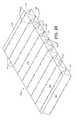
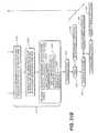
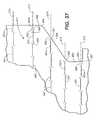
- slits 243can be shifted along bend line 243 to change the width of straps 247 without increasing jog distance at which the slits are laterally spaced from each other. Conversely, the jog distance between slits 243 can be increased and the slits longitudinally shifted to maintain the same strap thickness. Obviously both changes can be made to design the strap width and length to meet the application.
- the bending strap shapealso will influence the distribution of stresses across the bend.
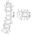
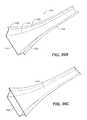
- the bending strapdiverges relatively rapidly away from the narrowest strap width dimension, e.g., width dimension 552 in FIG. 11 , there is a tendency for this minimum dimension to act as a waist or weakened plane at the center of the strap.
- Such rapid narrowingwill allow localized plastic deformation and stress concentration in the strap, rather than the desired distribution of the stresses over the full length of the strap and into the sheet material 554 and 556 on either side of the strap.
- the methods and apparatus of the three reel-to-reel processing systems described above, combined with the low bending-force, high strength bend features of the present invention,enable a class of products, from beams, to ladders, to building stud and joist systems, to be formed, coiled, subsequently uncoiled and folded into deterministic dimensions of impressive structural integrity, when and where they are needed after compact storage or transport in coiled form.
- This techniquehas applications in space, in the military, in commercial and residential construction and many other industries where the costs and effort of getting materials to a site are prohibitively expensive and difficult when parts are already in an assembled state.
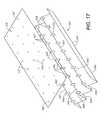
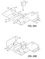
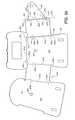
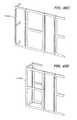
- the slitting and grooving method and apparatus of the present inventionensures the precise positioning of the opposed edges of the sheet 341 and openings 346 and tabs 348 so as to enable closure of structure 350 .
- the bends produced by slits 343can be adhesively or otherwise filled, for example, by welding or brazing. It is also possible to provide numerous other closure configurations or fastening schemes, including welding along the abutting edges of sheet 341 and overlapping of an edge of the sheet with a side wall and the use of tabs and/or fasteners.
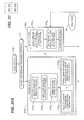
- CAD design steps 370 b and 370 ccan include various alternative sub-steps.
- a common approachis sub-step 370 b 1 in which the conceptual design is built in 3-D CAD and then flattened.
- the designcan be built up by successively bending sheet flanges or portions.
- Onecan also design in 2-D and declare or locate the bend lines, which is sub-step 370 b 3 . Placement of the proper or best-designed slits or grooves of the present invention can be done through software, at step 370 b 4 or manually at the step 370 b 5 .
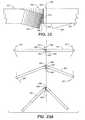
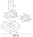
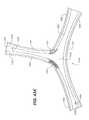
- one or more than one of the finger tabs 1437are stamped. Stamping may form curved portion 1440 , as well turn distal ends of a finger tab out of the original plane of sheet 1430 . In stamping the sheet in and around nexus (or hub) region 1436 , with respect to finger tabs 1437 or otherwise, progressive dies may be utilized.
Landscapes
- Engineering & Computer Science (AREA)
- Architecture (AREA)
- Structural Engineering (AREA)
- Civil Engineering (AREA)
- Mechanical Engineering (AREA)
- Electromagnetism (AREA)
- Physics & Mathematics (AREA)
- Bending Of Plates, Rods, And Pipes (AREA)
- Shaping Of Tube Ends By Bending Or Straightening (AREA)
- Prostheses (AREA)
- Emergency Lowering Means (AREA)
- Orthopedics, Nursing, And Contraception (AREA)
- Professional, Industrial, Or Sporting Protective Garments (AREA)
Abstract
Description


Claims (21)
Priority Applications (2)
| Application Number | Priority Date | Filing Date | Title |
|---|---|---|---|
| US13/010,626US8377566B2 (en) | 2002-09-26 | 2011-01-20 | Precision-folded, high strength, fatigue-resistant structures and sheet therefor |
| US13/466,564US20120276330A1 (en) | 2002-09-26 | 2012-05-08 | Precision-folded, high strength, fatigue-resistant structures and sheet therefor |
Applications Claiming Priority (6)
| Application Number | Priority Date | Filing Date | Title |
|---|---|---|---|
| US10/256,870US6877349B2 (en) | 2000-08-17 | 2002-09-26 | Method for precision bending of sheet of materials, slit sheets fabrication process |
| US10/672,766US7152449B2 (en) | 2000-08-17 | 2003-09-26 | Techniques for designing and manufacturing precision-folded, high strength, fatigue-resistant structures and sheet therefor |
| US66339205P | 2005-03-17 | 2005-03-17 | |
| US11/384,216US7534501B2 (en) | 2000-08-17 | 2006-03-16 | Precision-folded, high strength, fatigue-resistant structures and sheet therefor |
| US12/468,654US20090297740A1 (en) | 2000-08-17 | 2009-05-19 | Precision-folded, high strength, fatigue-resistant structures and sheet therefor |
| US13/010,626US8377566B2 (en) | 2002-09-26 | 2011-01-20 | Precision-folded, high strength, fatigue-resistant structures and sheet therefor |
Related Parent Applications (1)
| Application Number | Title | Priority Date | Filing Date |
|---|---|---|---|
| US12/468,654ContinuationUS20090297740A1 (en) | 2000-08-17 | 2009-05-19 | Precision-folded, high strength, fatigue-resistant structures and sheet therefor |
Related Child Applications (1)
| Application Number | Title | Priority Date | Filing Date |
|---|---|---|---|
| US13/466,564ContinuationUS20120276330A1 (en) | 2002-09-26 | 2012-05-08 | Precision-folded, high strength, fatigue-resistant structures and sheet therefor |
Publications (2)
| Publication Number | Publication Date |
|---|---|
| US20110287228A1 US20110287228A1 (en) | 2011-11-24 |
| US8377566B2true US8377566B2 (en) | 2013-02-19 |
Family
ID=37024422
Family Applications (5)
| Application Number | Title | Priority Date | Filing Date |
|---|---|---|---|
| US11/384,216Expired - Fee RelatedUS7534501B2 (en) | 2000-08-17 | 2006-03-16 | Precision-folded, high strength, fatigue-resistant structures and sheet therefor |
| US12/468,654AbandonedUS20090297740A1 (en) | 2000-08-17 | 2009-05-19 | Precision-folded, high strength, fatigue-resistant structures and sheet therefor |
| US13/010,619Expired - Fee RelatedUS8114524B2 (en) | 2002-09-26 | 2011-01-20 | Precision-folded, high strength, fatigue-resistant structures and sheet therefor |
| US13/010,626Expired - Fee RelatedUS8377566B2 (en) | 2002-09-26 | 2011-01-20 | Precision-folded, high strength, fatigue-resistant structures and sheet therefor |
| US13/466,564AbandonedUS20120276330A1 (en) | 2002-09-26 | 2012-05-08 | Precision-folded, high strength, fatigue-resistant structures and sheet therefor |
Family Applications Before (3)
| Application Number | Title | Priority Date | Filing Date |
|---|---|---|---|
| US11/384,216Expired - Fee RelatedUS7534501B2 (en) | 2000-08-17 | 2006-03-16 | Precision-folded, high strength, fatigue-resistant structures and sheet therefor |
| US12/468,654AbandonedUS20090297740A1 (en) | 2000-08-17 | 2009-05-19 | Precision-folded, high strength, fatigue-resistant structures and sheet therefor |
| US13/010,619Expired - Fee RelatedUS8114524B2 (en) | 2002-09-26 | 2011-01-20 | Precision-folded, high strength, fatigue-resistant structures and sheet therefor |
Family Applications After (1)
| Application Number | Title | Priority Date | Filing Date |
|---|---|---|---|
| US13/466,564AbandonedUS20120276330A1 (en) | 2002-09-26 | 2012-05-08 | Precision-folded, high strength, fatigue-resistant structures and sheet therefor |
Country Status (14)
| Country | Link |
|---|---|
| US (5) | US7534501B2 (en) |
| EP (1) | EP1861561A2 (en) |
| JP (1) | JP2008532775A (en) |
| KR (1) | KR20070112414A (en) |
| CN (1) | CN101233286A (en) |
| AU (1) | AU2006227372A1 (en) |
| BR (1) | BRPI0609143A2 (en) |
| CA (1) | CA2601585A1 (en) |
| IL (1) | IL186012A0 (en) |
| MX (1) | MX2007011397A (en) |
| RU (1) | RU2007138421A (en) |
| TW (1) | TW200704856A (en) |
| WO (1) | WO2006102089A2 (en) |
| ZA (1) | ZA200708852B (en) |
Cited By (8)
| Publication number | Priority date | Publication date | Assignee | Title |
|---|---|---|---|---|
| US20080187427A1 (en)* | 2000-08-17 | 2008-08-07 | Industrial Origami, Inc. | Load-bearing three-dimensional structure |
| US20090205387A1 (en)* | 2008-02-16 | 2009-08-20 | Industrial Origami, Inc. | System for low-force roll folding and methods thereof |
| US20110008573A1 (en)* | 2009-02-10 | 2011-01-13 | Industrial Origami, Inc. | Sheet of material with bend-controlling structures and method |
| US20120202669A1 (en)* | 2010-06-07 | 2012-08-09 | Robert Joseph Hannum | Method of Folding Sheet Materials Via Angled Torsional Strips |
| US8936164B2 (en) | 2012-07-06 | 2015-01-20 | Industrial Origami, Inc. | Solar panel rack |
| US20150165635A1 (en)* | 2012-07-19 | 2015-06-18 | Voith Patent Gmbh | Cutting device and method for cross-cutting a moving fiber web |
| US11015347B2 (en) | 2017-03-22 | 2021-05-25 | Marte And Marte Limited | Arbitrarily curved support structure |
| US12082708B2 (en) | 2021-12-17 | 2024-09-10 | Charleston Fab Lab, LLC | Flexible sling chair with living hinge |
Families Citing this family (80)
| Publication number | Priority date | Publication date | Assignee | Title |
|---|---|---|---|---|
| US6877349B2 (en)* | 2000-08-17 | 2005-04-12 | Industrial Origami, Llc | Method for precision bending of sheet of materials, slit sheets fabrication process |
| US20060048421A1 (en)* | 2004-09-03 | 2006-03-09 | Oleksak Mark W | Display board with header |
| AU2006227372A1 (en)* | 2005-03-17 | 2006-09-28 | Industrial Origami, Inc. | Precision-folded, high strength, fatigue-resistant structures and sheet therefor |
| JP2007253287A (en)* | 2006-03-24 | 2007-10-04 | Yamazaki Mazak Corp | Manufacturing method of sheet metal product with three-dimensional shape, and product |
| US7887249B2 (en)* | 2006-06-15 | 2011-02-15 | The Boeing Company | Internal finger joint |
| MX2009004478A (en) | 2006-10-26 | 2009-05-28 | Ind Origami Inc | Forming three dimensional object. |
| TW200904561A (en)* | 2007-04-15 | 2009-02-01 | Ind Origami Inc | Method and apparatus for forming bend controlling displacements in sheet material |
| TW200904560A (en)* | 2007-04-15 | 2009-02-01 | Ind Origami Inc | Method and apparatus for folding of sheet materials |
| NZ556782A (en)* | 2007-07-27 | 2010-03-26 | Armorflex Ltd | Method of producing a frangible post |
| US20090100893A1 (en)* | 2007-09-23 | 2009-04-23 | Industrial Origami, Inc. | Method of forming two-dimensional sheet material into three-dimensional structure |
| US8234901B2 (en) | 2007-10-25 | 2012-08-07 | The Boeing Company | Method to create bends in composite panels |
| US8312754B2 (en) | 2007-10-25 | 2012-11-20 | The Boeing Company | Method for forming bends in composite panels and composite panels made thereby |
| KR100958845B1 (en)* | 2007-11-06 | 2010-05-19 | 주식회사 서울레이저발형시스템 | Metal sheet bending device |
| US7891507B2 (en)* | 2007-12-20 | 2011-02-22 | Jakie Shetler | Storage rack decking derived from a single sheet of sheet metal |
| US20090178458A1 (en)* | 2008-01-10 | 2009-07-16 | Hirotec America, Inc. | Two die process |
| EP2105815B1 (en)* | 2008-03-25 | 2016-03-09 | TRUMPF Maschinen Grüsch AG | Method for creating a NC control program |
| US8830223B2 (en)* | 2008-05-08 | 2014-09-09 | Esko Software Bvba | Computer aided design of three-dimensional cartons with curved creases |
| US20100045017A1 (en)* | 2008-08-19 | 2010-02-25 | Rea James Robert | Tanks and methods of contstructing tanks |
| US20100122563A1 (en)* | 2008-11-16 | 2010-05-20 | Industrial Origami, Inc. | Method and apparatus for forming bend-controlling straps in sheet material |
| US8337051B2 (en)* | 2009-02-25 | 2012-12-25 | Koninklijke Philips Electronics N.V. | Reflector assembly and method of making same |
| DE102009046619B4 (en)* | 2009-11-11 | 2016-10-06 | Trumpf Werkzeugmaschinen Gmbh + Co. Kg | Process for producing a one-piece corner joint |
| WO2011120541A1 (en)* | 2010-04-01 | 2011-10-06 | Metawell Gmbh Metal Sandwich Technology | Method for producing a supporting element and supporting element for a reflector element |
| US20110245950A1 (en)* | 2010-04-06 | 2011-10-06 | Cvg Management Corporation | Vehicle body structure and method for making same |
| US8372495B2 (en) | 2010-05-26 | 2013-02-12 | Apple Inc. | Electronic device enclosure using sandwich construction |
| CN201774795U (en)* | 2010-07-07 | 2011-03-23 | 鸿富锦精密工业(深圳)有限公司 | Electromagnetic shielding cover |
| US8359801B2 (en)* | 2010-08-02 | 2013-01-29 | Usg Interiors, Llc | Grid runner |
| JP4856269B1 (en)* | 2010-09-06 | 2012-01-18 | 株式会社東芝 | Wiring design support apparatus and wiring design support method |
| CN102000721B (en)* | 2010-10-06 | 2013-02-20 | 江苏银河电子股份有限公司 | Method for positioning irregular metal plate during bending |
| GB201020152D0 (en)* | 2010-11-29 | 2011-01-12 | Airbus Uk Ltd | Aircraft panel structure and aircraft panel structure manufacturing method for alleviation of stress |
| JP5890683B2 (en)* | 2011-01-28 | 2016-03-22 | キヤノン株式会社 | Information processing apparatus and method |
| US20120193136A1 (en)* | 2011-01-31 | 2012-08-02 | Laird Technologies, Inc. | Folding Methods for Making Frames of Board Level Electromagnetic Interference (EMI) Shields |
| CN103476999B (en)* | 2011-02-25 | 2015-06-24 | Ces控制机柜系统有限公司 | A method for producing rectangular or square wall elements from flat sheet metal, and wall elements produced therewith |
| US10314594B2 (en) | 2012-12-14 | 2019-06-11 | Corquest Medical, Inc. | Assembly and method for left atrial appendage occlusion |
| US10307167B2 (en) | 2012-12-14 | 2019-06-04 | Corquest Medical, Inc. | Assembly and method for left atrial appendage occlusion |
| US10813630B2 (en) | 2011-08-09 | 2020-10-27 | Corquest Medical, Inc. | Closure system for atrial wall |
| US10220426B2 (en)* | 2012-01-10 | 2019-03-05 | Seoul Laser Dieboard System Co., Ltd | Device and method for generating channel letters |
| GB201202142D0 (en)* | 2012-02-08 | 2012-03-21 | British American Tobacco Co | A pack |
| GB201202273D0 (en)* | 2012-02-09 | 2012-03-28 | Modular Walling Systems Ltd | Modular construction system |
| US9686867B2 (en)* | 2012-09-17 | 2017-06-20 | Massachussetts Institute Of Technology | Foldable machines |
| US20140142689A1 (en) | 2012-11-21 | 2014-05-22 | Didier De Canniere | Device and method of treating heart valve malfunction |
| FR3001945B1 (en)* | 2013-02-14 | 2017-04-28 | Gaztransport Et Technigaz | WATERPROOF AND THERMALLY INSULATING WALL FOR FLUID STORAGE TANK |
| US10407955B2 (en) | 2013-03-13 | 2019-09-10 | Apple Inc. | Stiff fabric |
| KR20180021228A (en)* | 2013-05-13 | 2018-02-28 | 신닛테츠스미킨 카부시키카이샤 | Blank, molded plate, method of manufacturing press-molded product and press-molded product |
| CN103256473A (en)* | 2013-05-28 | 2013-08-21 | 常熟市平冶机械有限公司 | Rectangular tooth plate |
| US9205616B2 (en) | 2013-10-11 | 2015-12-08 | The Boeing Company | Bends in composite panels |
| US9566443B2 (en) | 2013-11-26 | 2017-02-14 | Corquest Medical, Inc. | System for treating heart valve malfunction including mitral regurgitation |
| TWI626345B (en) | 2013-12-20 | 2018-06-11 | 蘋果公司 | Woven fibric band, method of generating a securement mechanism for a woven fibric band and method for generating a woven fibric band for securement to an object |
| US10071487B2 (en) | 2014-05-06 | 2018-09-11 | Massachusetts Institute Of Technology | Systems and methods for compiling robotic assemblies |
| DE202014104104U1 (en)* | 2014-09-02 | 2014-09-26 | Metawell Gmbh Metal Sandwich Technology | Filled metal sandwich structure |
| CN104265756B (en)* | 2014-09-03 | 2017-02-15 | 奇瑞汽车股份有限公司 | Diesel engine connecting rod and manufacturing method thereof |
| US10842626B2 (en) | 2014-12-09 | 2020-11-24 | Didier De Canniere | Intracardiac device to correct mitral regurgitation |
| WO2016144317A1 (en)* | 2015-03-09 | 2016-09-15 | Halliburton Energy Services, Inc. | Collapsible wiring conduit for downhole linear actuator |
| US10478975B2 (en)* | 2015-04-10 | 2019-11-19 | Worcester Polytechnic Institute | Fabrication of robotic mechanisms and systems from planar substrates |
| US20160327275A1 (en)* | 2015-05-04 | 2016-11-10 | Eugene Baker | Stove Service Tray |
| ITUB20154818A1 (en)* | 2015-10-22 | 2017-04-22 | Angelo Candiracci | STRUCTURE OF ANTI-DRILL BUILDING PANEL |
| FR3049639B1 (en)* | 2016-04-04 | 2018-04-13 | Hall Systems | METHOD FOR IMPLEMENTING A CHASSIS AND CHASSIS THUS OBTAINED |
| US9812828B1 (en)* | 2016-05-27 | 2017-11-07 | Scott Hunter | Wedge shaped power station and related methods |
| WO2018155698A1 (en)* | 2017-02-27 | 2018-08-30 | Vivita株式会社 | Cad device and program |
| CN110494328B (en)* | 2017-04-10 | 2023-07-04 | 日本制铁株式会社 | Structural components for automobiles |
| DE202017104977U1 (en)* | 2017-08-18 | 2018-08-21 | Mayr-Melnhof Karton Ag | Blank, resulting three-dimensional structure and carton |
| US10251304B1 (en)* | 2017-09-20 | 2019-04-02 | Mitek Corp,. Inc. | Lightweight electronics rack |
| US10864686B2 (en) | 2017-09-25 | 2020-12-15 | Apple Inc. | Continuous carbon fiber winding for thin structural ribs |
| US10428522B2 (en)* | 2017-09-25 | 2019-10-01 | Pravin Nanayakkara | Construction metallic trapezoidal systems |
| EP3498391B1 (en) | 2017-12-13 | 2019-11-13 | Ovh | Rigid sheet blank and method for producing same |
| KR102690964B1 (en) | 2018-06-27 | 2024-08-02 | 엘지전자 주식회사 | Vacuum adiabatic body and refrigerator |
| KR102608948B1 (en)* | 2018-06-27 | 2023-12-04 | 엘지전자 주식회사 | Vacuum adiabatic body and refrigerator |
| WO2020025095A1 (en)* | 2018-08-02 | 2020-02-06 | Knauf Gips Kg | Stud for a wall construction |
| CN109227961B (en)* | 2018-08-30 | 2020-12-01 | 公安部四川消防研究所 | A kind of processing method of helium explosion-proof decompression plate |
| WO2020051126A1 (en)* | 2018-09-04 | 2020-03-12 | Cortex Composites, Inc. | Cementitious composite structure |
| CN112272592B (en)* | 2019-01-29 | 2022-11-29 | 温州美葆科技技术有限公司 | Method for producing a plurality of supporting ribs and method for producing a plurality of razor blades |
| US10953451B2 (en)* | 2019-02-21 | 2021-03-23 | Friedrich Graepel Ag | Metal sheet with contour cut for vibration reduction |
| DE102019115174A1 (en)* | 2019-06-05 | 2020-12-10 | Lübbers Anlagen- und Umwelttechnik GmbH | Process for manufacturing a perforated sheet, perforated sheet, molded part and processing device |
| CN112046626B (en)* | 2019-06-05 | 2023-09-19 | 天津天汽集团有限公司 | Rear guide plate and vehicle |
| US20220259855A1 (en)* | 2019-06-26 | 2022-08-18 | Formflow Pty Ltd | Structural member for a modular building |
| WO2021155424A1 (en)* | 2020-02-07 | 2021-08-12 | Roy Tiles Pty Limited | Handle attachment for an adhesive spreader |
| US11643783B2 (en)* | 2020-03-24 | 2023-05-09 | Samuel, Son & Co., Limited | Simplified steel orthotropic deck bridge panel |
| CN112635954B (en)* | 2020-12-07 | 2022-12-16 | 上海卫星工程研究所 | Foldable space antenna on-orbit unfolding self-locking driving hinge and control method thereof |
| CN113028161A (en)* | 2021-02-23 | 2021-06-25 | 南京联众工程技术有限公司 | Corrugated flange structure for circumferential connection of corrugated steel pipes and manufacturing method thereof |
| CN113843316B (en)* | 2021-10-08 | 2022-12-27 | 江苏兴达智能制造有限公司 | Bending method for preventing hole deformation |
| CN115464023A (en)* | 2022-09-21 | 2022-12-13 | 中国第一汽车股份有限公司 | Technological method for optimizing roof skylight flanging surface waves |
Citations (351)
| Publication number | Priority date | Publication date | Assignee | Title |
|---|---|---|---|---|
| US387651A (en) | 1888-08-14 | Hieam stevens maxim | ||
| US624144A (en) | 1899-05-02 | Metal tube | ||
| US649387A (en) | 1899-08-31 | 1900-05-08 | Thomas Wright | Hinge. |
| US649762A (en) | 1899-07-28 | 1900-05-15 | American Metal Edge Box Company | Mechanism for punching metal strips. |
| US800365A (en) | 1905-04-22 | 1905-09-26 | Franz Ebert | Process for manufacturing prismatically-hollowed sheet-metal characters. |
| US975121A (en) | 1910-01-27 | 1910-11-08 | James H Carter | Box. |
| US1295769A (en) | 1918-03-07 | 1919-02-25 | Chicago Metal Products Co | Method and means for producing cartridge-clips. |
| US1405042A (en) | 1919-03-21 | 1922-01-31 | Kraft Henry Phillip | Method of making dust caps for tire valves |
| US1468271A (en) | 1921-04-18 | 1923-09-18 | American Multigraph Co | Mechanism for making printing-strip holders |
| US1557066A (en) | 1921-02-14 | 1925-10-13 | Westinghouse Electric & Mfg Co | Box structure |
| US1698891A (en) | 1922-11-09 | 1929-01-15 | Flintkote Co | Strip roofing unit and process of manufacture |
| US1699693A (en) | 1927-03-22 | 1929-01-22 | Duro Co | Method of forming screen plate |
| US1746429A (en) | 1929-01-31 | 1930-02-11 | William G Kelleweay | Partition strip for composition flooring |
| US1810842A (en) | 1929-09-19 | 1931-06-16 | American Stove Co | Insulated range |
| US2127618A (en) | 1933-12-16 | 1938-08-23 | Midland Steel Prod Co | Method and apparatus for forming automobile side rails |
| US2158972A (en) | 1937-02-02 | 1939-05-16 | L F Grammes & Sons Inc | Box construction |
| US2339355A (en) | 1940-05-10 | 1944-01-18 | Rutten Walter | Apparatus for edging and forming |
| US2423863A (en) | 1940-11-16 | 1947-07-15 | George F Wales | Sheet metal compartment with shelf supports and method of manufacture |
| GB590720A (en) | 1945-03-26 | 1947-07-25 | George Francis John Dandridge | Method of securing metal plates together |
| US2480034A (en) | 1946-09-09 | 1949-08-23 | Chester A Lapp | Pipe fitting |
| US2484398A (en) | 1949-04-20 | 1949-10-11 | Gay Bell Corp | Machine for clinching a hoop connecting member and the like |
| US2512118A (en) | 1946-11-29 | 1950-06-20 | Avco Mfg Corp | Stove frame |
| US2515067A (en) | 1948-12-27 | 1950-07-11 | Guarantee Specialty Mfg Compan | Venetian blind bracket |
| US2560786A (en) | 1948-12-27 | 1951-07-17 | Guarantee Specialty Mfg Compan | Method of forming bracket units |
| US2625290A (en) | 1950-11-29 | 1953-01-13 | Coleman Co | Sheet assembly structure |
| US2638643A (en) | 1949-06-02 | 1953-05-19 | Kenneth T Snow | Building bracket |
| GB740933A (en) | 1953-07-02 | 1955-11-23 | Lucas Industries Ltd | A method of riveting together two pieces of material one at least of which consists of nylon or like material |
| US2771851A (en) | 1954-05-20 | 1956-11-27 | Lockheed Aircraft Corp | Sheet metal forming die means |
| US2825407A (en) | 1955-03-24 | 1958-03-04 | Plastic Binding Corp | Gang punch |
| US2869694A (en) | 1954-07-23 | 1959-01-20 | Air Filter Corp | Frame construction for filter units |
| US2880032A (en) | 1949-01-22 | 1959-03-31 | Barenyi Bela | Vehicle body composed of an upper and a lower section |
| US2882990A (en) | 1956-11-01 | 1959-04-21 | United States Gypsum Co | Sound absorbing units and method of making same |
| US2901155A (en) | 1955-12-21 | 1959-08-25 | Continental Paper Company | Carton |
| US2916181A (en) | 1954-10-06 | 1959-12-08 | Fed Pacific Electric Co | Sheet metal joint and box and method of making same |
| US2926831A (en) | 1957-08-30 | 1960-03-01 | John Strange Carton Co Inc | Infold carton with corner bracing strut |
| US2948624A (en) | 1954-12-16 | 1960-08-09 | Dighton L Watson | Expansible metal foil package |
| US2976747A (en) | 1953-08-25 | 1961-03-28 | Schatzschock Adolf | Method for forming filing tools |
| US3039414A (en) | 1960-05-31 | 1962-06-19 | Rosanes Jacob | Method of producing hollow four-sided tapering beams or columns from sheet metal |
| US3090087A (en)* | 1961-02-14 | 1963-05-21 | Peter H Miller | Stock material for use as edging strip |
| US3094229A (en) | 1960-09-16 | 1963-06-18 | Koehring Co | Hydraulic back hoe |
| US3094158A (en) | 1960-06-27 | 1963-06-18 | Standard Products Co | Mechanism for forming prongs or barbs in sheet metal strips |
| US3095134A (en) | 1960-03-23 | 1963-06-25 | Reynolds Metals Co | Lined container for liquids and liner therefor |
| US3107041A (en) | 1961-01-31 | 1963-10-15 | Mead Corp | Reinforced folded blank carton |
| US3107807A (en) | 1961-02-23 | 1963-10-22 | Bergh Bros Co | Box wall and base combination |
| US3120257A (en) | 1960-04-23 | 1964-02-04 | Baustahlgewebe Gmbh | Device for bending steel mesh for reinforced concrete and the like |
| GB955666A (en) | 1960-01-19 | 1964-04-15 | Elm Works Ltd | Improvements in and relating to tools for performing punching, pressing or like operations |
| US3135527A (en) | 1961-07-28 | 1964-06-02 | Philip B Knapp | Wheeled market carts |
| US3156232A (en) | 1961-09-19 | 1964-11-10 | Tappan Co | Range chassis |
| US3159156A (en) | 1961-12-28 | 1964-12-01 | Arthur E Incledon | Disposable oven liner |
| US3191564A (en) | 1963-05-15 | 1965-06-29 | Ermal C Fraze | Method of fabricating a sheet metal joint |
| US3216644A (en) | 1962-02-14 | 1965-11-09 | Henry C Harrison | Disposable sink strainer |
| US3217437A (en) | 1964-05-18 | 1965-11-16 | Chicago Show Printing Company | Pole sign |
| US3228710A (en) | 1965-05-18 | 1966-01-11 | Strachan & Henshaw Ltd | Folding of paper and like material |
| US3258380A (en) | 1958-12-22 | 1966-06-28 | St Regis Paper Co | Method and apparatus for making lug liner |
| US3313080A (en) | 1962-02-07 | 1967-04-11 | Wood Marc Sa | Sandwich structure with novel core element |
| US3318301A (en) | 1965-06-24 | 1967-05-09 | Westinghouse Electric Corp | Range body construction |
| US3341395A (en) | 1962-12-03 | 1967-09-12 | Solar Reflection Room Corp | Lightweight structural panel |
| US3353639A (en) | 1964-06-17 | 1967-11-21 | Peugeot Et Cie Sa | Strip providing coupling elements coupling, with regard to rotation, two concentric members, the elements obtained from said strip and assemblies employing said element |
| US3357078A (en) | 1966-08-01 | 1967-12-12 | Floyd J Moltchan | Apparatus for punching interlocking tabs in steel strips |
| US3361320A (en) | 1964-08-20 | 1968-01-02 | Victor Bobrowski | Tapered-tube-making device |
| US3455018A (en) | 1965-11-08 | 1969-07-15 | Microdot Inc | Method of making sealing strip |
| US3474225A (en) | 1967-08-24 | 1969-10-21 | Tappan Co The | Forced air electric oven |
| US3521536A (en) | 1965-09-23 | 1970-07-21 | Finn Ind Inc | Plunger and die mechanism for forming trays |
| US3538982A (en) | 1969-10-21 | 1970-11-10 | United Aircraft Corp | Twisted splitter for fluid stream |
| US3590759A (en) | 1969-11-19 | 1971-07-06 | George S Hendrie Jr | Reinforcing strip for plastic articles and method and apparatus for making same |
| US3626604A (en) | 1969-06-23 | 1971-12-14 | James B Pierce | Three-dimensional chemical models |
| US3638597A (en) | 1969-09-26 | 1972-02-01 | Fraze Ermal C | Method of forming a rivet |
| US3638465A (en) | 1969-03-10 | 1972-02-01 | Flangeklamp Corp | Method of forming a structural element |
| US3666607A (en) | 1968-09-03 | 1972-05-30 | Joel J Weissman | Blank for constructing solid forms |
| US3688385A (en) | 1969-11-04 | 1972-09-05 | Fraze Ermal C | Method of making a riveted jointure |
| US3717022A (en) | 1972-03-07 | 1973-02-20 | Bois E Du | Press device |
| US3731514A (en) | 1971-02-07 | 1973-05-08 | A Deibele | Cleat bender |
| US3756499A (en) | 1972-03-09 | 1973-09-04 | Union Camp Corp | Box with five panel ends |
| US3774434A (en) | 1971-09-14 | 1973-11-27 | R Bock | Arrangement for bending of bars of reinforcing steel mats |
| US3779282A (en) | 1971-11-08 | 1973-12-18 | Boeing Co | Annulus inverting valve |
| US3788934A (en) | 1971-10-01 | 1974-01-29 | A Coppa | Three-dimensional folded structure with curved surfaces |
| US3851912A (en) | 1972-02-28 | 1974-12-03 | Citroen Sa | Vehicle with flat frame structure |
| US3854859A (en) | 1972-10-19 | 1974-12-17 | M Sola | Shaping head for plastic molding machines |
| US3862562A (en) | 1972-06-05 | 1975-01-28 | Johannes Petrus Kruger | Method of shaping ductile sheet material and apparatus therefor |
| US3867829A (en) | 1972-08-02 | 1975-02-25 | Rudolf Bock | Adjustable arrangement for bending of bars of reinforcing steel mats |
| US3878438A (en) | 1973-09-28 | 1975-04-15 | William Jacobs A K A Calmark | Printed circuit card guide |
| US3879240A (en) | 1973-08-17 | 1975-04-22 | Raymond W Wall | Method of making a unitary camper structure |
| US3882653A (en) | 1971-06-30 | 1975-05-13 | C O Inc | Truss construction |
| US3890869A (en) | 1972-11-29 | 1975-06-24 | Mark Products Corp Van | Louver cutter |
| US3907193A (en) | 1974-04-08 | 1975-09-23 | Autoplex Corp | Plastic folding containers and process and apparatus for making same |
| US3914974A (en) | 1974-04-19 | 1975-10-28 | William Devore | Lithographic plate bending arrangement |
| US3938657A (en) | 1972-11-16 | 1976-02-17 | David Melvin J | Blind rivet assembly |
| US3943744A (en) | 1974-06-19 | 1976-03-16 | Tapco Products Company, Inc. | Louver cutter |
| US3952574A (en) | 1974-10-31 | 1976-04-27 | Speidel John A | Process and apparatus for forming sheet metal structures |
| US3963170A (en) | 1974-11-29 | 1976-06-15 | The Mead Corporation | Panel interlocking means and blank utilizing said means |
| US3994275A (en) | 1975-04-21 | 1976-11-30 | Marianne M. Williams | Free-standing, disposable fireplace reflector |
| US4004334A (en) | 1974-11-05 | 1977-01-25 | Greenley Henry R | Method of making a structural member |
| US4011704A (en) | 1971-08-30 | 1977-03-15 | Wheeling-Pittsburgh Steel Corporation | Non-ghosting building construction |
| US4027340A (en) | 1976-03-15 | 1977-06-07 | Robert Hain Associates, Inc. | Face mask |
| US4058813A (en) | 1976-03-18 | 1977-11-15 | Rca Corporation | Sheet metal waveguide horn antenna |
| US4102525A (en) | 1977-02-14 | 1978-07-25 | Robert Norman Albano | Knockdown support and spacer for bookshelves |
| US4120084A (en) | 1976-05-12 | 1978-10-17 | Knut Olof Lennart Wallman | Method of making improved lug and hole connection between sheet metal elements |
| US4132026A (en) | 1977-04-25 | 1979-01-02 | J. J. Dill Company | Simplified blank forming a rodent poison container |
| US4133198A (en) | 1976-07-09 | 1979-01-09 | Balcke-Durr Aktiengesellschaft | Apparatus for bending large area construction units |
| US4133336A (en) | 1977-09-29 | 1979-01-09 | Smith Alva T | Ventilated stove |
| US4141525A (en) | 1977-11-10 | 1979-02-27 | Knape & Vogt Manufacturing Co. | Universal drawer slide mounting bracket |
| US4145801A (en) | 1978-02-13 | 1979-03-27 | Aluminum Company Of America | Method of forming an integral rivet for an easy open can end |
| US4166565A (en) | 1978-06-08 | 1979-09-04 | Champion International Corporation | Air freshener carton |
| US4170691A (en) | 1975-09-11 | 1979-10-09 | Rogers J W | Steel metal web handling method, apparatus, and coil construct |
| US4190190A (en) | 1978-05-09 | 1980-02-26 | Okuli Oy | Strip made up of consecutive package blanks |
| US4215194A (en) | 1978-02-21 | 1980-07-29 | Masterwork, Inc. | Method for forming three-dimensional objects from sheet metal |
| US4230058A (en) | 1978-02-24 | 1980-10-28 | Yuwa-Sangyo Kabushiki-Kaisha | Method and apparatus for manufacturing box-shaped structure from metal sheet |
| US4245615A (en) | 1979-04-30 | 1981-01-20 | Magic Chef, Inc. | Modular range construction |
| US4289290A (en) | 1977-11-10 | 1981-09-15 | Knape & Vogt Manufacturing Co. | Universal drawer slide mounting bracket |
| US4327835A (en) | 1980-01-10 | 1982-05-04 | Honeywell Information Systems Inc. | Universal snap-in card guide for printed circuit card enclosures |
| US4352843A (en) | 1980-08-21 | 1982-10-05 | Thomas A. Schutz Co., Inc. | Component for a multiplanar device |
| US4362519A (en) | 1977-01-20 | 1982-12-07 | Robert Gault | Boat hulls |
| US4383430A (en) | 1979-12-22 | 1983-05-17 | Rolf Peddinghaus | Bending machine |
| US4401341A (en) | 1980-03-17 | 1983-08-30 | Nissan Motor Co., Ltd. | Panel reinforcement structure construction |
| US4428599A (en) | 1982-02-01 | 1984-01-31 | The Budd Company | Front and rear energy absorbing structures for a four passenger vehicle |
| GB2129339A (en) | 1982-10-29 | 1984-05-16 | Kenneth Carter | A method of forming a sheet |
| US4457555A (en) | 1981-07-10 | 1984-07-03 | Cars & Concepts, Inc. | Conversion of vehicle bodies |
| US4469727A (en) | 1981-09-02 | 1984-09-04 | The Standard Products Company | Automotive trim strip with expanded pressure sensitive tape |
| US4468946A (en) | 1982-06-30 | 1984-09-04 | Kelley Company Inc. | Method of making lambda beams |
| US4469273A (en) | 1983-06-02 | 1984-09-04 | Weyerhaeuser Company | Self-unlocking container closure |
| US4479737A (en) | 1982-02-01 | 1984-10-30 | Bergh Bros. Co., Inc. | Positive interlock |
| US4489976A (en) | 1982-12-09 | 1984-12-25 | Flaherty B Michael | Vehicle body |
| US4491362A (en) | 1981-09-23 | 1985-01-01 | Kennedy Thomas H | Automotive fiberglass body |
| JPS6061237A (en) | 1983-09-14 | 1985-04-09 | Yamaha Motor Co Ltd | Manufacture of car body of synthetic resin |
| US4510785A (en) | 1981-07-07 | 1985-04-16 | Ets. Y. Jouanel S.A. | Automatic sheet metal folding machine |
| US4515004A (en) | 1982-10-07 | 1985-05-07 | Jenglo Engineering, Inc. | Welded wire fabric bending apparatus and method |
| US4542933A (en) | 1981-02-06 | 1985-09-24 | Rainer Bischoff | Camper superstructure |
| US4557132A (en) | 1984-02-03 | 1985-12-10 | Tapco Products Company, Inc. | Sheet bending brake |
| US4558582A (en) | 1982-10-13 | 1985-12-17 | Manfred Meinig | Apparatus for flanging ventilation duct walls |
| US4559259A (en) | 1979-10-18 | 1985-12-17 | Tetra Pak International Ab | Packing laminate provided with crease lines |
| US4597374A (en) | 1981-06-16 | 1986-07-01 | Sharp Kabushiki Kaisha | Construction of a heating compartment for cooking apparatus |
| GB2174781A (en) | 1985-03-25 | 1986-11-12 | Erhard Christensen | Interlocking joint for materials in sheet form |
| US4628661A (en)* | 1984-09-06 | 1986-12-16 | Camco Inc. | Scored metal appliance frame |
| US4645701A (en) | 1986-02-24 | 1987-02-24 | Zarrow Scott F | Credit card carbon copy defacer |
| US4650217A (en) | 1984-01-09 | 1987-03-17 | Konstruktionsatelje AkeÅhrlund | Continuous strip of mutually hinged panels |
| JPS6294474A (en) | 1985-10-21 | 1987-04-30 | Nissan Motor Co Ltd | Connection structure of vehicle body frame members |
| US4672718A (en) | 1985-03-21 | 1987-06-16 | Louis F. Arnone, III | Gold-crowned domed garment button and manufacturing method |
| DE3642208A1 (en) | 1985-12-11 | 1987-06-25 | Hitachi Ltd | METHOD FOR PRODUCING WORKPIECES IN THE FORM OF SHELLS WITH A CURVED SURFACE |
| US4676545A (en) | 1981-07-06 | 1987-06-30 | Bonfilio Paul F | Modular chassis for land, sea and air vehicles |
| US4735077A (en) | 1985-08-09 | 1988-04-05 | U.S. Philips Corporation | Method of and device for impressing channels having a small cross-sectional area into the surface of an object |
| GB2197457A (en) | 1986-11-10 | 1988-05-18 | Ti New World Ltd | Cooking appliances |
| JPS63134381A (en) | 1986-11-26 | 1988-06-06 | Tsubakimoto Chain Co | Body frame structure for vehicle |
| US4760634A (en) | 1985-09-14 | 1988-08-02 | Eugen Rapp | Method of connecting thin plates |
| JPS63263176A (en) | 1987-04-17 | 1988-10-31 | Mazda Motor Corp | Front part body structure of automobile |
| JPS63263175A (en) | 1987-04-17 | 1988-10-31 | Mazda Motor Corp | Front part body structure of automobile |
| US4792082A (en) | 1987-03-03 | 1988-12-20 | Williamson Gaylord L | Enclosed animal litter box |
| US4803879A (en) | 1986-12-30 | 1989-02-14 | Crawford Robert J | Slip lock forming apparatus |
| US4819792A (en) | 1986-02-03 | 1989-04-11 | Christian George T | Folding display |
| US4831711A (en) | 1987-04-01 | 1989-05-23 | Eugen Rapp | Method for joining thin plates stacked on one another |
| US4837066A (en) | 1986-05-29 | 1989-06-06 | Gates Formed-Fibre Products, Inc. | Foldable rigidified textile panels |
| US4869539A (en) | 1987-06-16 | 1989-09-26 | Ferrari Engineering S.P.A. | Supporting structure for a motor vehicle |
| US4887862A (en) | 1986-08-07 | 1989-12-19 | Alfa Lancia Industriale S.R.L. | Bodywork for a vehicle, in particular for an automobile, and process for manufacturing it |
| US4898326A (en) | 1987-10-28 | 1990-02-06 | Kadee Metal Products Co. | Track joining system |
| US4950026A (en) | 1988-10-06 | 1990-08-21 | Emmons J Bruce | Passenger vehicle body frame |
| US4951967A (en) | 1987-09-16 | 1990-08-28 | Koenig & Bauer Aktiengesellschaft | Signature perforating knife and signature |
| DE3906958A1 (en) | 1988-12-05 | 1990-09-06 | Kuhn Rainer | Method for manufacturing flat components |
| NL8900776A (en) | 1989-03-29 | 1990-10-16 | Joseph Antonius Catharinus Vli | Cardboard box - comprises side panels hinging via fold lines on base panel with two opposite side panels each having vertical flaps |
| US5022804A (en) | 1989-02-14 | 1991-06-11 | Buell Industries, Inc. | Self-mounting fastener |
| US5077601A (en) | 1988-09-09 | 1991-12-31 | Hitachi, Ltd. | Cooling system for cooling an electronic device and heat radiation fin for use in the cooling system |
| US5105640A (en) | 1991-01-25 | 1992-04-21 | Iowa Precision Industries, Inc. | Method and apparatus for forming box-shaped sheet metal ducts |
| US5148900A (en) | 1991-06-25 | 1992-09-22 | New Venture Gear, Inc. | Viscous coupling apparatus with coined plates and method of making the same |
| US5148600A (en) | 1991-09-17 | 1992-09-22 | Advanced Robotics (A.R.L.) Ltd. | Precision measuring apparatus |
| US5157852A (en) | 1990-07-23 | 1992-10-27 | Patrou Louis G | Three dimensional paper structure enclosed in a transparent box |
| US5195644A (en) | 1992-07-13 | 1993-03-23 | Glenayre Electronics Ltd. | Sealed, seamless box and method of manufacturing same |
| US5205476A (en) | 1992-06-12 | 1993-04-27 | Perseco Division Of The Havi Group Lp | Clamshell carton having an improved latching mechanism |
| US5211330A (en) | 1991-04-08 | 1993-05-18 | Albert Frey Verpackungsentwicklungen Und Vertriebes-Gmbh | Five-speed box foldable from a blank and useful as an open container, or as an end lid for a larger package |
| US5211047A (en) | 1991-03-12 | 1993-05-18 | Toyota Jidosha Kabushiki Kaisha | Die for bending a composite flange having a stretch portion and a straight portion |
| US5225799A (en) | 1991-06-04 | 1993-07-06 | California Amplifier | Microwave filter fabrication method and filters therefrom |
| US5227176A (en) | 1991-12-06 | 1993-07-13 | Monsanto Company | Mold for a shaped laminate |
| US5234246A (en) | 1991-05-24 | 1993-08-10 | Ecia | Dashboard |
| US5234727A (en) | 1991-07-19 | 1993-08-10 | Charles Hoberman | Curved pleated sheet structures |
| US5239741A (en) | 1992-08-27 | 1993-08-31 | Shamos Desmond E | Method of fabricating a pillow casing apparatus |
| US5255969A (en) | 1991-02-28 | 1993-10-26 | Rheem Manufacturing Company | Double-walled cabinet structure for air conditioning equipment |
| US5259100A (en) | 1992-05-27 | 1993-11-09 | Amada Engineering & Service Co., Inc. | Milling tool for turret punch press |
| US5262220A (en) | 1991-06-18 | 1993-11-16 | Chem-Tronics, Inc. | High strength structure assembly and method of making the same |
| US5284043A (en) | 1992-09-29 | 1994-02-08 | Amada Manufacturing America Inc. | Method and device for separating a contoured product from sheet metal |
| US5297836A (en) | 1991-07-03 | 1994-03-29 | Jaguar Cars Limited | Motor car chasis structure |
| US5302435A (en) | 1992-03-24 | 1994-04-12 | Mitsubishi Plastics Industries Limited | Plastic sheet with a ruled line for bending |
| US5316165A (en) | 1991-04-11 | 1994-05-31 | Qube Corporation | Foldable electrical component enclosures |
| US5333519A (en) | 1981-09-08 | 1994-08-02 | Ameritek, Inc. | Steel rule die and method |
| US5362120A (en) | 1993-04-05 | 1994-11-08 | Ford Motor Company | Vehicle body construction and method for inspection of adhesively secured joints therein |
| US5372026A (en) | 1989-11-29 | 1994-12-13 | Armco Steel Company | Apparatus and method for hydroforming sheet metal |
| US5390782A (en) | 1992-06-19 | 1995-02-21 | United States Surgical Corporation | Needle shield device for surgical packages |
| US5392629A (en) | 1993-10-26 | 1995-02-28 | Canoga Industries Inc. | Method and apparatus for forming multi-level features in an object |
| US5415021A (en) | 1993-10-29 | 1995-05-16 | Folmer; Carroll W. | Apparatus for high pressure hydraulic forming of sheet metal blanks, flat patterns, and piping |
| US5427732A (en) | 1993-12-28 | 1995-06-27 | Shuert; Lyle H. | Method of forming deep draw twin sheet plastic articles |
| US5432989A (en) | 1992-10-27 | 1995-07-18 | Archer Manufacturing Corporation | Apparatus and method for joining sheet material |
| US5440450A (en) | 1990-09-14 | 1995-08-08 | Next, Inc. | Housing cooling system |
| US5460773A (en) | 1993-08-11 | 1995-10-24 | Fritz; Michael L. | Seal for blow down platen |
| US5466146A (en) | 1992-06-29 | 1995-11-14 | Fritz; Michael L. | Hydroforming platen and seal |
| US5475911A (en) | 1993-05-20 | 1995-12-19 | Wells; Gary L. | Multi-stage dual wall hydroforming |
| US5496067A (en) | 1993-10-05 | 1996-03-05 | Smh Management Services Ag | Chassis for vehicles notably for motor vehicles |
| US5497825A (en) | 1995-05-24 | 1996-03-12 | Symphony Group International Co., Ltd. | Heat-radiator for CPU of a computer |
| US5524396A (en) | 1993-06-10 | 1996-06-11 | Lalvani; Haresh | Space structures with non-periodic subdivisions of polygonal faces |
| US5533444A (en) | 1994-01-07 | 1996-07-09 | Food And Agrosystems, Inc. | High air velocity convection oven |
| US5568680A (en) | 1995-01-26 | 1996-10-29 | Regent Lighting Corporation | Method for making a reflector for a luminaire |
| US5571280A (en) | 1995-05-25 | 1996-11-05 | Photofabrication Engineering Inc. | Lampshade |
| US5587914A (en) | 1989-09-22 | 1996-12-24 | Hewlett-Packard Company | Apparatus and method for computer-aided design of sheet metal fabricated parts |
| US5592363A (en) | 1992-09-30 | 1997-01-07 | Hitachi, Ltd. | Electronic apparatus |
| US5620623A (en) | 1994-07-21 | 1997-04-15 | Whirlpool Corporation | Thermal blend convection oven |
| US5619784A (en) | 1991-05-10 | 1997-04-15 | Mazda Motor Corporation | Vehicle assembling method |
| US5630469A (en) | 1995-07-11 | 1997-05-20 | International Business Machines Corporation | Cooling apparatus for electronic chips |
| US5640046A (en) | 1994-05-27 | 1997-06-17 | Fujitsu Limited | Cooling structure for integrated circuit element modules, electronic device and heat sink block |
| US5660365A (en) | 1995-09-29 | 1997-08-26 | Glick; Isaac N. | Display easel |
| US5692672A (en) | 1996-09-03 | 1997-12-02 | Jefferson Smurfit Corporation | Container end closure arrangement |
| US5701780A (en) | 1994-12-19 | 1997-12-30 | Pella Corporation | Installation fin for windows and doors |
| US5704212A (en) | 1996-09-13 | 1998-01-06 | Itronix Corporation | Active cooling system for cradle of portable electronic devices |
| US5709913A (en) | 1992-08-11 | 1998-01-20 | E. Khashoggi Industries | Method and apparatus for manufacturing articles of manufacture from sheets having a highly inorganically filled organic polymer matrix |
| US5725147A (en) | 1994-05-06 | 1998-03-10 | Tetra Laval Holdings & Finance S.A. | Gable top carton and carton blank with curved side creases |
| US5737226A (en) | 1995-06-05 | 1998-04-07 | Prince Corporation | Vehicle compass system with automatic calibration |
| US5740589A (en) | 1995-05-26 | 1998-04-21 | Mikalor, S.A. | Means for clasping the extremities of the metal sheet forming tie-bands |
| US5789050A (en)* | 1996-11-12 | 1998-08-04 | Xynatech, Inc. | Perforating and slitting die sheet, methods of constructing same and paper product produced therefrom |
| US5828575A (en) | 1996-05-06 | 1998-10-27 | Amadasoft America, Inc. | Apparatus and method for managing and distributing design and manufacturing information throughout a sheet metal production facility |
| EP0873858A1 (en) | 1995-12-27 | 1998-10-28 | Hitachi Zosen Corporation | Fold construction of corrugated fiberboard |
| DE29818909U1 (en) | 1998-10-23 | 1998-12-24 | Fortmeier, Josef, 33758 Schloß Holte-Stukenbrock | Bent sheet metal part |
| US5882064A (en) | 1996-04-30 | 1999-03-16 | Autokinetics, Inc. | Modular vehicle frame |
| US5885676A (en) | 1995-07-06 | 1999-03-23 | Magnetek, Inc. | Plastic tube and method and apparatus for manufacturing |
| DE19746931C1 (en) | 1997-10-23 | 1999-06-10 | Ulrich Sommer | Rear independent suspension for motor vehicle |
| US6021042A (en) | 1997-08-06 | 2000-02-01 | Intel Corporation | Cooling duct for a computer cooling system with redundant air moving units |
| US6055788A (en) | 1997-08-02 | 2000-05-02 | Daimlerchrysler Ag | Longitudinal frame support for a commercial vehicle and process for producing the same |
| US6065323A (en) | 1997-05-27 | 2000-05-23 | Amada Company, Limited | Method and apparatus for the production of bent sheet metal pieces |
| US6071574A (en) | 1997-07-11 | 2000-06-06 | Southpac Trust International, Inc. | Folded corrugated material and method for producing same |
| JP2000198153A (en) | 1999-01-06 | 2000-07-18 | Tanakaya Inc | Edge stop fold fixing structure |
| US6144896A (en) | 1998-03-04 | 2000-11-07 | Amada Metrecs Company, Limited | Method and apparatus for designing sheet metal parts |
| US6158652A (en) | 1999-08-13 | 2000-12-12 | Georgia-Pacific Corporation | Container with wall locking feature |
| DE19951850C1 (en) | 1999-10-28 | 2001-01-25 | Metallwarenfabrik Reichertshof | Production of molded parts comprises arranging a sheet steel between a molding tool and a membrane, molding the steel sheet against the molding tool, and releasing the pressure after complete deformation of the steel sheet |
| TW422735B (en) | 1997-05-22 | 2001-02-21 | L Air Liquide Sa Pour L Expl | Mass- and heat-exchange device and a process for manufacturing the device |
| US6194653B1 (en) | 1998-03-24 | 2001-02-27 | General Instrument Corporation | Enclosure design having an integrated system of retention, electromagnetic interference containment and structural load distribution |
| US6210037B1 (en)* | 1999-01-26 | 2001-04-03 | Daniel M. Brandon, Jr. | Back pack liner |
| TW431422U (en) | 2000-08-22 | 2001-04-21 | Sea Wave Entpr Ltd | Box body structure |
| US6220654B1 (en) | 1997-02-28 | 2001-04-24 | Ulrich Sommer | Passenger car |
| US6233538B1 (en) | 1997-09-11 | 2001-05-15 | Amada America, Inc. | Apparatus and method for multi-purpose setup planning for sheet metal bending operations |
| US20010010167A1 (en) | 1999-03-10 | 2001-08-02 | Simpson Strong-Tie Company, Inc. | Method for forming a short-radius bend in flanged sheet metal member |
| TW451896U (en) | 2001-01-19 | 2001-08-21 | Juo Chi Ming | Improved structure for box body |
| TW451893U (en) | 2001-01-19 | 2001-08-21 | Juo Chi Ming | Improved structure for packing box |
| US6279288B1 (en) | 1998-04-16 | 2001-08-28 | Kurt A. Keil | Structural tubing members with flared out end segments for conjoining |
| US6296301B1 (en) | 1999-12-21 | 2001-10-02 | Daimlerchrysler Corporation | Motor vehicle body structure using a woven fiber |
| US6296300B1 (en) | 1999-07-15 | 2001-10-02 | Nissan Motor Co., Ltd. | Vehicle body structure |
| US6299240B1 (en) | 2000-05-18 | 2001-10-09 | Daimlerchrysler Corporation | Lightweight vehicle frame construction using stiff torque boxes |
| US6330153B1 (en) | 1999-01-14 | 2001-12-11 | Nokia Telecommunications Oy | Method and system for efficiently removing heat generated from an electronic device |
| US6373696B1 (en) | 1998-06-15 | 2002-04-16 | Compaq Computer Corporation | Hard drive cooling using finned heat sink and thermally conductive interface pad |
| US6386009B1 (en) | 2000-11-21 | 2002-05-14 | General Motors Corporation | Method and apparatus for hydroforming multiple components with reduced press loading |
| US6391424B1 (en) | 1999-04-30 | 2002-05-21 | Kunitsugu Suzuki | Plastic sheet having creasing lines |
| US6400012B1 (en) | 1997-09-17 | 2002-06-04 | Advanced Energy Voorhees, Inc. | Heat sink for use in cooling an integrated circuit |
| US6412325B1 (en) | 1999-03-23 | 2002-07-02 | 3 Dimensional Services | Method for phototyping parts from sheet metal |
| US6467475B2 (en) | 2000-07-05 | 2002-10-22 | Schott Glas | Stove for cooking food with a viewing window, and a viewing window for household appliances, such as cooking stoves or ovens |
| US20020153371A1 (en) | 2001-03-13 | 2002-10-24 | Matsushita Electric Industrial Co., Ltd. | High-frequency heating apparatus and cooling system for magnetron-driving power supply utilized in the apparatus |
| US20020163173A1 (en) | 2001-05-07 | 2002-11-07 | Ruehl Phillip C. | Contoured hip/straight member vehicle frame |
| US6481259B1 (en)* | 2000-08-17 | 2002-11-19 | Castle, Inc. | Method for precision bending of a sheet of material and slit sheet therefor |
| US6490498B1 (en) | 1998-06-05 | 2002-12-03 | Amada Company, Limited | Integrated support system for supporting sheet metal machining |
| US20020185892A1 (en) | 2001-05-08 | 2002-12-12 | Sergio Rima | Support frame for a motor vehicle, and motor vehicle provided with such a support frame |
| US20020184936A1 (en)* | 1999-01-27 | 2002-12-12 | Bruce Gitlin | Method of bending sheet metal to form three-dimensional structures |
| US20030037586A1 (en)* | 2000-08-17 | 2003-02-27 | Durney Max W. | Method for precision bending of sheet of materials, slit sheets fabrication process |
| US20030062739A1 (en) | 2000-08-03 | 2003-04-03 | L&L Products | Sound absorption system for automotive vehicles |
| US6558775B1 (en) | 1999-08-27 | 2003-05-06 | Kunitsugu Suzuki | Plastic sheet having creasing lines and creasing line-forming blade for plastic sheet |
| US20030104916A1 (en) | 2001-12-03 | 2003-06-05 | Kunitsugu Suzuki | Plastic sheet having creasing lines and creasing-line-forming blade for plastic sheet |
| US6588244B2 (en) | 2000-09-26 | 2003-07-08 | Airbus France | Process for hydroforming sheet metal and device for practicing the same |
| US6592174B1 (en) | 1999-02-05 | 2003-07-15 | Alcan Technology & Management Ltd. | Structural support |
| US6599601B2 (en) | 2000-08-24 | 2003-07-29 | Paxar Corporation | Composite label web and method of using same |
| TW544356B (en) | 2001-08-23 | 2003-08-01 | Rung-Ju Jau | Method for machining screw cutting edge of elongated cutting edge drill bit |
| US6626560B1 (en) | 2000-11-22 | 2003-09-30 | Ronald N. Caferro | Lighting louver |
| US6631630B1 (en) | 2000-09-22 | 2003-10-14 | Board Of Trustees Of Michigan State University | Hydroforming of composite materials |
| US6643561B1 (en) | 1999-12-30 | 2003-11-04 | Abb Technology Ag | Parametric programming of laser cutting system |
| US6640599B1 (en) | 1999-03-18 | 2003-11-04 | Abb Ab | Tool for automatic roll folding |
| US6647693B2 (en) | 2002-03-15 | 2003-11-18 | Howard M. Bromberg | Three-dimensional structures of sheet material |
| US6648159B2 (en) | 1995-09-20 | 2003-11-18 | Vladimir Prutkin | Collapsible three-dimensional enclosure, and a method of manufacturing thereof |
| US6658316B1 (en) | 1999-12-30 | 2003-12-02 | Abb Technology Ag | Parametric programming of robots and automated machines for manufacturing electrical enclosures |
| US6688043B1 (en) | 1997-05-06 | 2004-02-10 | Brose Fahrzeugteile Gmbh & Co. Kg | Device and method for securing a component to a support part in a vehicle |
| US20040035175A1 (en) | 2000-09-26 | 2004-02-26 | Markku Karhumaki | Plate processing device and method for processing a plate |
| US6722013B1 (en) | 1998-03-25 | 2004-04-20 | Tox Pressotechnik Gmbh | Method, tool and punch for joining components to a plate |
| US20040076800A1 (en) | 2000-06-29 | 2004-04-22 | Roland Noilhan | Precut plate for obtaining a volume, in particular a package, method for making same and resulting package |
| US6728114B2 (en) | 2002-07-05 | 2004-04-27 | Alcatel Canada Inc. | Space-saving card guides for card cage and method of installing same on a card cage or frame |
| US20040079353A1 (en) | 2001-03-08 | 2004-04-29 | Panagopoulos Dimitrios | Roaster with cover |
| US20040103707A1 (en) | 2000-12-12 | 2004-06-03 | Andreas Winters | Internal high pressure forming device and method and corresponding tool system |
| US6745608B2 (en) | 2001-12-10 | 2004-06-08 | Shinkoh Co., Ltd. | Hemming units and apparatus |
| US20040130182A1 (en) | 2000-12-23 | 2004-07-08 | Bayerische Motoren Werke Aktiengesellschaft | Flat section of the outer skin of the bodywork of a motor vehicle |
| US6761502B2 (en) | 2000-03-01 | 2004-07-13 | Rolls-Royce Plc | Joint for sheet material and a method of joining sheet material |
| US20040206152A1 (en) | 2000-08-17 | 2004-10-21 | Durney Max W. | Sheet material with bend controlling displacements and method for forming the same |
| US20040207228A1 (en) | 2002-09-27 | 2004-10-21 | Girma Gebreselassie | Vehicle cockpit assemblies having integrated dash insulators, instrument panels and floor coverings, and methods of installing same within vehicles |
| US6831255B1 (en) | 2003-09-11 | 2004-12-14 | Maytag Corporation | Combination radiant/convection cooking system for an electric oven |
| US6837334B1 (en) | 1998-03-27 | 2005-01-04 | Dominic Le Prevost | Acoustic horn |
| US20050005670A1 (en) | 2000-08-17 | 2005-01-13 | Durney Max W. | Method of designing fold lines in sheet material |
| US20050042432A1 (en) | 2003-08-20 | 2005-02-24 | Jones John M. | Liner panel having barrier layer |
| US6868708B2 (en) | 2000-02-22 | 2005-03-22 | Avestapolarit Ab | Blank guided forming |
| US20050061049A1 (en)* | 2000-08-17 | 2005-03-24 | Durney Max W. | Process of forming bend-controlling structures in a sheet of material, the resulting sheet and die sets therefor |
| US20050088014A1 (en) | 2003-09-02 | 2005-04-28 | Woodson Brett N. | Load floor assembly |
| EP1529575A2 (en) | 2003-11-04 | 2005-05-11 | Umformtechnik Alfred Burggraf GmbH | Bulk material sorter |
| US20050097937A1 (en)* | 2000-08-17 | 2005-05-12 | Durney Max W. | Sheet material with bend controlling grooves defining a continuous web across a bend line and method for forming the same |
| US20050117300A1 (en) | 2003-03-31 | 2005-06-02 | Ravi Prasher | Channeled heat sink and chassis with integrated heat rejecter for two-phase cooling |
| US20050120766A1 (en) | 2003-12-05 | 2005-06-09 | Ford Global Technologies, Llc | Apparatus and method for forming an article and performing a secondary operation in-situ |
| US6917017B2 (en) | 2002-08-23 | 2005-07-12 | Heartware Home Products, Inc. | Counter-top cooker having multiple heating elements |
| US20050161979A1 (en) | 2004-01-23 | 2005-07-28 | Chernoff Adrian B. | Vehicle body compartment lid having unitary inner panel and outer panel |
| US20050168014A1 (en) | 2004-01-30 | 2005-08-04 | Chernoff Adrian B. | Integrated front assembly |
| US20050167459A1 (en) | 2004-02-02 | 2005-08-04 | Storer Ron D. | Truck sports rack |
| US20050174732A1 (en) | 2004-02-06 | 2005-08-11 | Fang-Cheng Lin | Main unit of a computer |
| US6936795B1 (en) | 2004-04-14 | 2005-08-30 | Hearthware Home Products, Inc. | Method and apparatus for securing a power head on an electric cooker |
| US20050189790A1 (en) | 2004-02-27 | 2005-09-01 | Chernoff Adrian B. | Automotive side frame and upper structure and method of manufacture |
| US20050189791A1 (en) | 2004-02-27 | 2005-09-01 | Chernoff Adrian B. | Automotive lower body component and method of manufacture |
| US6940716B1 (en) | 2000-07-13 | 2005-09-06 | Intel Corporation | Method and apparatus for dissipating heat from an electronic device |
| US6941786B1 (en) | 2004-03-25 | 2005-09-13 | Ford Global Technologies, Llc | Component specific tube blanks for hydroforming body structure components |
| US20050257589A1 (en) | 2000-08-17 | 2005-11-24 | Industrial Origami, Llc | Sheet material with bend controlling displacements and method for forming the same |
| US20050284088A1 (en) | 1999-03-31 | 2005-12-29 | Heath Mark D | Structural panel and method of fabrication |
| US6986273B2 (en) | 2003-06-20 | 2006-01-17 | Dana Corporation | Apparatus and method for opening and closing stacked hydroforming dies |
| US20060021413A1 (en) | 2000-08-17 | 2006-02-02 | Durney Max W | Fatigue-resistance sheet slitting method and resulting sheet |
| US7000978B1 (en) | 2004-08-20 | 2006-02-21 | Frank Messano | Thin-skin ultralight recreational vehicle body system |
| US20060044755A1 (en) | 2004-08-24 | 2006-03-02 | Fujitsu Limited | Electronic apparatus with a cooling redundancy function |
| US20060053857A1 (en) | 2004-09-10 | 2006-03-16 | Durney Max W | Tool system for bending sheet materials and method of using same |
| US7014174B2 (en) | 2003-07-01 | 2006-03-21 | Adobeair | Evaporative cooling system |
| US20060059807A1 (en) | 2004-09-10 | 2006-03-23 | Jim Zimmerman | Frame system for motor vehicle |
| US20060096100A1 (en) | 2000-11-22 | 2006-05-11 | Israel Stol | Joint structure and method for making a joint structure |
| US7051768B2 (en) | 2001-05-22 | 2006-05-30 | Mitsubishi Jidosha Kogyo Kabushiki Kaisha | Hydroform process and hydroform product |
| US20060130551A1 (en) | 2004-12-16 | 2006-06-22 | Industrial Origam, Llc | Method of bending sheet materials and sheet therefor |
| US7069758B2 (en) | 2004-08-11 | 2006-07-04 | Joseph Kariakin | Metal stud punch system and a method of manufacture |
| US20060175871A1 (en) | 2002-08-27 | 2006-08-10 | Konrad Eipper | Motor vehicle body |
| US20060181846A1 (en) | 2005-02-11 | 2006-08-17 | Farnsworth Arthur K | Cooling system for a computer environment |
| US7099160B1 (en) | 2002-10-31 | 2006-08-29 | Finisar Corporation | Card guide systems and devices |
| US20060207212A1 (en) | 2000-08-17 | 2006-09-21 | Industrial Origami, Llc | Precision-folded, high strength, fatigue-resistant structures and sheet therefor |
| US20060213245A1 (en) | 2000-08-17 | 2006-09-28 | Industrial Origami, Llc | Method and tooling for forming sheet material with bend controlling displacements |
| US20060232934A1 (en) | 2005-04-15 | 2006-10-19 | Kabushiki Kaisha Toshiba | Electronic apparatus |
| US20060232052A1 (en) | 1995-06-07 | 2006-10-19 | Automotive Technologies International, Inc. | Vehicular Bus Including Crash Sensor or Occupant Protection System Control Module |
| US7126819B2 (en) | 2004-04-14 | 2006-10-24 | Hsien-Rong Liang | Chassis air guide thermal cooling solution |
| US20060237996A1 (en) | 2002-08-27 | 2006-10-26 | Konrad Eipper | Motor vehicle body comprising a support structure made of large-size partial modules |
| US20060261139A1 (en) | 2000-08-17 | 2006-11-23 | Industrial Origami, Llc | Apparatus and method for joining the edges of folded sheet material to form three-dimensional structure |
| US20060277965A1 (en) | 2000-08-17 | 2006-12-14 | Industrial Origami, Llc | Three-dimensional structure formed with precision fold technology and method of forming same |
| GB2427399A (en) | 2005-06-22 | 2006-12-27 | Aquasol Ltd | Blank for container with curved walls |
| CN1292106C (en) | 2005-06-30 | 2006-12-27 | 上海交通大学 | Growth method of yttrium aluminate crystal |
| US7156200B2 (en) | 2001-04-19 | 2007-01-02 | Caterpillar S.A.R.L. | Main frame for a tracked skid steer loader machine |
| US7167380B2 (en) | 2002-08-13 | 2007-01-23 | Finisar Corporation | Card cage system |
| US7185934B2 (en) | 2003-05-12 | 2007-03-06 | Nissan Motor Co., Ltd. | Vehicle body structure |
| US20070117502A1 (en) | 2005-11-22 | 2007-05-24 | Gateway Inc. | Adjustable cooling air duct for use with components of different sizes |
| US20070123113A1 (en) | 2005-09-23 | 2007-05-31 | Industrial Origami, Inc. | Method for Forming Angles and Closures in Sheet Material and Sheet Therefor |
| US20070146988A1 (en) | 2005-12-22 | 2007-06-28 | Kabushiki Kaisha Toshiba | Electronic apparatus |
| US7243519B1 (en) | 2005-03-23 | 2007-07-17 | Sen-Jung Chuang | Roll-forming machine |
| US7264304B2 (en) | 2001-10-16 | 2007-09-04 | Ferrari S.P.A. | Vehicle body |
| US20070206353A1 (en) | 2006-03-06 | 2007-09-06 | Cisco Technology, Inc. | Efficient airflow management |
| US7275403B2 (en) | 2005-12-15 | 2007-10-02 | Englert, Inc. | Longitudinal curvature adjustment assembly for a rain gutter roll forming machine |
| US20070231062A1 (en) | 2005-12-22 | 2007-10-04 | Industrial Origami, Llc | Method for joining planar sheets and sheets therefor |
| US7281754B2 (en) | 2005-01-24 | 2007-10-16 | Behr Eugene E | Flexible panel system |
| US20070241587A1 (en) | 2006-04-14 | 2007-10-18 | Fleming Sean M | Reduced Weight Components for Vehicle Frame and Method of Making Same |
| US20070262128A1 (en) | 2006-05-09 | 2007-11-15 | Industrial Origami, Inc. | Precision folded vehicular structural and aesthetic component and sheet therefor |
| US20070271793A1 (en) | 2003-10-20 | 2007-11-29 | Magna International Inc. | Hybrid Component |
| US20070286722A1 (en) | 2006-06-12 | 2007-12-13 | Asia Vital Components Co.,Ltd. | Structure of air duct and manufacturing process of the same |
| US7331505B2 (en) | 2005-11-28 | 2008-02-19 | Meadwestvaco Packaging Systems, Llc | Carton for tapered articles |
| US20080048366A1 (en) | 2006-08-28 | 2008-02-28 | Industrial Origami, Inc. | Method and Apparatus For Imparting Compound Folds on Sheet Material |
| US20080054683A1 (en) | 2006-09-06 | 2008-03-06 | Nissan Motor Co., Ltd. | Car body frame member |
| US20080098787A1 (en) | 2006-10-26 | 2008-05-01 | Industrial Origami, Inc. | Method of forming two-dimensional sheet material into three-dimensional structure |
| US20080187427A1 (en) | 2000-08-17 | 2008-08-07 | Industrial Origami, Inc. | Load-bearing three-dimensional structure |
| US20080250837A1 (en) | 2007-04-15 | 2008-10-16 | Industrial Origami, Inc. | Method and apparatus for folding of sheet materials |
| US20080276682A1 (en) | 2007-04-15 | 2008-11-13 | Industrial Origami, Inc. | Method and apparatus for forming bend controlling displacements in sheet material |
| US7503623B2 (en) | 2003-12-19 | 2009-03-17 | Ferrari S.P.A. | Metal frame made up of the union of a plurality of extruded elements, and method for its fabrication |
| US20100201158A1 (en) | 2007-09-21 | 2010-08-12 | Toyota Jidosha Kabushiki Kaisha | Formed part for vehicle body structural member |
Family Cites Families (23)
| Publication number | Priority date | Publication date | Assignee | Title |
|---|---|---|---|---|
| US3246796A (en)* | 1964-01-21 | 1966-04-19 | Robert A Euglander | Divisible carton |
| JPS5268848A (en) | 1975-12-05 | 1977-06-08 | Nippon Electric Co | Method of reducing warp in press bending |
| JPS5370069A (en) | 1976-12-02 | 1978-06-22 | Nippon Electric Co | Working method of electron panel fitting plate |
| JPS5522468A (en) | 1978-08-05 | 1980-02-18 | Takubo Kogyosho:Kk | Molding method of metal plate |
| JPS5555222A (en) | 1978-10-19 | 1980-04-23 | Shinichi Sugino | Liquid level detector |
| JPS6037318Y2 (en)* | 1981-08-05 | 1985-11-07 | 澁谷工業株式会社 | packaging box body |
| JPS596116A (en) | 1982-06-30 | 1984-01-13 | Nissan Motor Co Ltd | Seal structure around window |
| GB8416542D0 (en)* | 1984-06-28 | 1984-08-01 | Mead Corp | Multipack for containers |
| US5390762A (en)* | 1987-08-14 | 1995-02-21 | Power Plus Corporation | Automatic crankcase oil change and makeup system |
| JPH0627225Y2 (en) | 1988-11-01 | 1994-07-27 | 船井電機株式会社 | Parts mounting plate |
| JPH02165817A (en) | 1988-12-16 | 1990-06-26 | Anritsu Corp | Metallic plate and bending method therefor |
| JPH0696171B2 (en) | 1989-01-21 | 1994-11-30 | 株式会社田窪工業所 | Metal plate molding method |
| JP2818434B2 (en) | 1989-03-30 | 1998-10-30 | 株式会社アマダ | 3D parts manufacturing method |
| JPH0433723A (en) | 1990-05-25 | 1992-02-05 | Toshiba Corp | Manufacturing method of bent metal plate products |
| JPH0491822A (en) | 1990-08-08 | 1992-03-25 | Amada Co Ltd | Blank layout for solid part |
| JP3519095B2 (en) | 1992-01-21 | 2004-04-12 | 株式会社アマダ | Plate material bending method and bending method |
| JPH07148528A (en) | 1993-11-30 | 1995-06-13 | Honda Motor Co Ltd | Press molding method |
| US5452799A (en)* | 1994-06-14 | 1995-09-26 | Riverwood International Corporation | Article carrier with rounded corners |
| JPH08224619A (en) | 1995-02-22 | 1996-09-03 | Amada Co Ltd | Work bending method and device therefor |
| JPH1085837A (en) | 1996-09-13 | 1998-04-07 | Mitsubishi Electric Corp | Hand bent plate removal structure for sheet metal parts |
| US5855275A (en)* | 1997-10-10 | 1999-01-05 | Riverwood International Corporation | Two-tiered carton for flanged articles |
| JPH11123458A (en) | 1997-10-27 | 1999-05-11 | Meiji Natl Ind Co Ltd | Structure for bending metallic sheet |
| JP3675148B2 (en) | 1997-12-26 | 2005-07-27 | 株式会社イトーキクレビオ | Method for manufacturing channel member by roll forming method |
- 2006
- 2006-03-16AUAU2006227372Apatent/AU2006227372A1/ennot_activeAbandoned
- 2006-03-16JPJP2008502100Apatent/JP2008532775A/ennot_activeAbandoned
- 2006-03-16USUS11/384,216patent/US7534501B2/ennot_activeExpired - Fee Related
- 2006-03-16TWTW095108993Apatent/TW200704856A/enunknown
- 2006-03-16CACA002601585Apatent/CA2601585A1/ennot_activeAbandoned
- 2006-03-16MXMX2007011397Apatent/MX2007011397A/enactiveIP Right Grant
- 2006-03-16RURU2007138421/03Apatent/RU2007138421A/ennot_activeApplication Discontinuation
- 2006-03-16WOPCT/US2006/009729patent/WO2006102089A2/enactiveApplication Filing
- 2006-03-16KRKR1020077023824Apatent/KR20070112414A/ennot_activeWithdrawn
- 2006-03-16ZAZA200708852Apatent/ZA200708852B/enunknown
- 2006-03-16EPEP06738753Apatent/EP1861561A2/ennot_activeWithdrawn
- 2006-03-16CNCNA2006800164753Apatent/CN101233286A/enactivePending
- 2006-03-16BRBRPI0609143-1Apatent/BRPI0609143A2/ennot_activeIP Right Cessation
- 2007
- 2007-09-17ILIL186012Apatent/IL186012A0/enunknown
- 2009
- 2009-05-19USUS12/468,654patent/US20090297740A1/ennot_activeAbandoned
- 2011
- 2011-01-20USUS13/010,619patent/US8114524B2/ennot_activeExpired - Fee Related
- 2011-01-20USUS13/010,626patent/US8377566B2/ennot_activeExpired - Fee Related
- 2012
- 2012-05-08USUS13/466,564patent/US20120276330A1/ennot_activeAbandoned
Patent Citations (396)
| Publication number | Priority date | Publication date | Assignee | Title |
|---|---|---|---|---|
| US387651A (en) | 1888-08-14 | Hieam stevens maxim | ||
| US624144A (en) | 1899-05-02 | Metal tube | ||
| US649762A (en) | 1899-07-28 | 1900-05-15 | American Metal Edge Box Company | Mechanism for punching metal strips. |
| US649387A (en) | 1899-08-31 | 1900-05-08 | Thomas Wright | Hinge. |
| US800365A (en) | 1905-04-22 | 1905-09-26 | Franz Ebert | Process for manufacturing prismatically-hollowed sheet-metal characters. |
| US975121A (en) | 1910-01-27 | 1910-11-08 | James H Carter | Box. |
| US1295769A (en) | 1918-03-07 | 1919-02-25 | Chicago Metal Products Co | Method and means for producing cartridge-clips. |
| US1405042A (en) | 1919-03-21 | 1922-01-31 | Kraft Henry Phillip | Method of making dust caps for tire valves |
| US1557066A (en) | 1921-02-14 | 1925-10-13 | Westinghouse Electric & Mfg Co | Box structure |
| US1468271A (en) | 1921-04-18 | 1923-09-18 | American Multigraph Co | Mechanism for making printing-strip holders |
| US1698891A (en) | 1922-11-09 | 1929-01-15 | Flintkote Co | Strip roofing unit and process of manufacture |
| US1699693A (en) | 1927-03-22 | 1929-01-22 | Duro Co | Method of forming screen plate |
| US1746429A (en) | 1929-01-31 | 1930-02-11 | William G Kelleweay | Partition strip for composition flooring |
| US1810842A (en) | 1929-09-19 | 1931-06-16 | American Stove Co | Insulated range |
| US2127618A (en) | 1933-12-16 | 1938-08-23 | Midland Steel Prod Co | Method and apparatus for forming automobile side rails |
| US2158972A (en) | 1937-02-02 | 1939-05-16 | L F Grammes & Sons Inc | Box construction |
| US2339355A (en) | 1940-05-10 | 1944-01-18 | Rutten Walter | Apparatus for edging and forming |
| US2423863A (en) | 1940-11-16 | 1947-07-15 | George F Wales | Sheet metal compartment with shelf supports and method of manufacture |
| GB590720A (en) | 1945-03-26 | 1947-07-25 | George Francis John Dandridge | Method of securing metal plates together |
| US2480034A (en) | 1946-09-09 | 1949-08-23 | Chester A Lapp | Pipe fitting |
| US2512118A (en) | 1946-11-29 | 1950-06-20 | Avco Mfg Corp | Stove frame |
| US2515067A (en) | 1948-12-27 | 1950-07-11 | Guarantee Specialty Mfg Compan | Venetian blind bracket |
| US2560786A (en) | 1948-12-27 | 1951-07-17 | Guarantee Specialty Mfg Compan | Method of forming bracket units |
| US2880032A (en) | 1949-01-22 | 1959-03-31 | Barenyi Bela | Vehicle body composed of an upper and a lower section |
| US2484398A (en) | 1949-04-20 | 1949-10-11 | Gay Bell Corp | Machine for clinching a hoop connecting member and the like |
| US2638643A (en) | 1949-06-02 | 1953-05-19 | Kenneth T Snow | Building bracket |
| US2625290A (en) | 1950-11-29 | 1953-01-13 | Coleman Co | Sheet assembly structure |
| GB740933A (en) | 1953-07-02 | 1955-11-23 | Lucas Industries Ltd | A method of riveting together two pieces of material one at least of which consists of nylon or like material |
| US2976747A (en) | 1953-08-25 | 1961-03-28 | Schatzschock Adolf | Method for forming filing tools |
| US2771851A (en) | 1954-05-20 | 1956-11-27 | Lockheed Aircraft Corp | Sheet metal forming die means |
| US2869694A (en) | 1954-07-23 | 1959-01-20 | Air Filter Corp | Frame construction for filter units |
| US2916181A (en) | 1954-10-06 | 1959-12-08 | Fed Pacific Electric Co | Sheet metal joint and box and method of making same |
| US2948624A (en) | 1954-12-16 | 1960-08-09 | Dighton L Watson | Expansible metal foil package |
| US2825407A (en) | 1955-03-24 | 1958-03-04 | Plastic Binding Corp | Gang punch |
| US2901155A (en) | 1955-12-21 | 1959-08-25 | Continental Paper Company | Carton |
| US2882990A (en) | 1956-11-01 | 1959-04-21 | United States Gypsum Co | Sound absorbing units and method of making same |
| US2926831A (en) | 1957-08-30 | 1960-03-01 | John Strange Carton Co Inc | Infold carton with corner bracing strut |
| US3258380A (en) | 1958-12-22 | 1966-06-28 | St Regis Paper Co | Method and apparatus for making lug liner |
| GB955666A (en) | 1960-01-19 | 1964-04-15 | Elm Works Ltd | Improvements in and relating to tools for performing punching, pressing or like operations |
| US3095134A (en) | 1960-03-23 | 1963-06-25 | Reynolds Metals Co | Lined container for liquids and liner therefor |
| US3120257A (en) | 1960-04-23 | 1964-02-04 | Baustahlgewebe Gmbh | Device for bending steel mesh for reinforced concrete and the like |
| US3039414A (en) | 1960-05-31 | 1962-06-19 | Rosanes Jacob | Method of producing hollow four-sided tapering beams or columns from sheet metal |
| US3094158A (en) | 1960-06-27 | 1963-06-18 | Standard Products Co | Mechanism for forming prongs or barbs in sheet metal strips |
| US3094229A (en) | 1960-09-16 | 1963-06-18 | Koehring Co | Hydraulic back hoe |
| US3107041A (en) | 1961-01-31 | 1963-10-15 | Mead Corp | Reinforced folded blank carton |
| US3090087A (en)* | 1961-02-14 | 1963-05-21 | Peter H Miller | Stock material for use as edging strip |
| US3107807A (en) | 1961-02-23 | 1963-10-22 | Bergh Bros Co | Box wall and base combination |
| US3135527A (en) | 1961-07-28 | 1964-06-02 | Philip B Knapp | Wheeled market carts |
| US3156232A (en) | 1961-09-19 | 1964-11-10 | Tappan Co | Range chassis |
| US3159156A (en) | 1961-12-28 | 1964-12-01 | Arthur E Incledon | Disposable oven liner |
| US3313080A (en) | 1962-02-07 | 1967-04-11 | Wood Marc Sa | Sandwich structure with novel core element |
| US3216644A (en) | 1962-02-14 | 1965-11-09 | Henry C Harrison | Disposable sink strainer |
| US3341395A (en) | 1962-12-03 | 1967-09-12 | Solar Reflection Room Corp | Lightweight structural panel |
| US3191564A (en) | 1963-05-15 | 1965-06-29 | Ermal C Fraze | Method of fabricating a sheet metal joint |
| US3217437A (en) | 1964-05-18 | 1965-11-16 | Chicago Show Printing Company | Pole sign |
| US3353639A (en) | 1964-06-17 | 1967-11-21 | Peugeot Et Cie Sa | Strip providing coupling elements coupling, with regard to rotation, two concentric members, the elements obtained from said strip and assemblies employing said element |
| US3361320A (en) | 1964-08-20 | 1968-01-02 | Victor Bobrowski | Tapered-tube-making device |
| US3228710A (en) | 1965-05-18 | 1966-01-11 | Strachan & Henshaw Ltd | Folding of paper and like material |
| US3318301A (en) | 1965-06-24 | 1967-05-09 | Westinghouse Electric Corp | Range body construction |
| US3521536A (en) | 1965-09-23 | 1970-07-21 | Finn Ind Inc | Plunger and die mechanism for forming trays |
| US3455018A (en) | 1965-11-08 | 1969-07-15 | Microdot Inc | Method of making sealing strip |
| US3357078A (en) | 1966-08-01 | 1967-12-12 | Floyd J Moltchan | Apparatus for punching interlocking tabs in steel strips |
| US3474225A (en) | 1967-08-24 | 1969-10-21 | Tappan Co The | Forced air electric oven |
| US3666607A (en) | 1968-09-03 | 1972-05-30 | Joel J Weissman | Blank for constructing solid forms |
| US3638465A (en) | 1969-03-10 | 1972-02-01 | Flangeklamp Corp | Method of forming a structural element |
| US3626604A (en) | 1969-06-23 | 1971-12-14 | James B Pierce | Three-dimensional chemical models |
| US3638597A (en) | 1969-09-26 | 1972-02-01 | Fraze Ermal C | Method of forming a rivet |
| US3538982A (en) | 1969-10-21 | 1970-11-10 | United Aircraft Corp | Twisted splitter for fluid stream |
| US3688385A (en) | 1969-11-04 | 1972-09-05 | Fraze Ermal C | Method of making a riveted jointure |
| US3590759A (en) | 1969-11-19 | 1971-07-06 | George S Hendrie Jr | Reinforcing strip for plastic articles and method and apparatus for making same |
| US3731514A (en) | 1971-02-07 | 1973-05-08 | A Deibele | Cleat bender |
| US3882653A (en) | 1971-06-30 | 1975-05-13 | C O Inc | Truss construction |
| US4011704A (en) | 1971-08-30 | 1977-03-15 | Wheeling-Pittsburgh Steel Corporation | Non-ghosting building construction |
| US3774434A (en) | 1971-09-14 | 1973-11-27 | R Bock | Arrangement for bending of bars of reinforcing steel mats |
| US3788934A (en) | 1971-10-01 | 1974-01-29 | A Coppa | Three-dimensional folded structure with curved surfaces |
| US3779282A (en) | 1971-11-08 | 1973-12-18 | Boeing Co | Annulus inverting valve |
| US3851912A (en) | 1972-02-28 | 1974-12-03 | Citroen Sa | Vehicle with flat frame structure |
| US3717022A (en) | 1972-03-07 | 1973-02-20 | Bois E Du | Press device |
| US3756499A (en) | 1972-03-09 | 1973-09-04 | Union Camp Corp | Box with five panel ends |
| US3862562A (en) | 1972-06-05 | 1975-01-28 | Johannes Petrus Kruger | Method of shaping ductile sheet material and apparatus therefor |
| US3867829A (en) | 1972-08-02 | 1975-02-25 | Rudolf Bock | Adjustable arrangement for bending of bars of reinforcing steel mats |
| US3854859A (en) | 1972-10-19 | 1974-12-17 | M Sola | Shaping head for plastic molding machines |
| US3938657A (en) | 1972-11-16 | 1976-02-17 | David Melvin J | Blind rivet assembly |
| US3890869A (en) | 1972-11-29 | 1975-06-24 | Mark Products Corp Van | Louver cutter |
| US3879240A (en) | 1973-08-17 | 1975-04-22 | Raymond W Wall | Method of making a unitary camper structure |
| US3878438A (en) | 1973-09-28 | 1975-04-15 | William Jacobs A K A Calmark | Printed circuit card guide |
| US3907193A (en) | 1974-04-08 | 1975-09-23 | Autoplex Corp | Plastic folding containers and process and apparatus for making same |
| US3914974A (en) | 1974-04-19 | 1975-10-28 | William Devore | Lithographic plate bending arrangement |
| US3943744A (en) | 1974-06-19 | 1976-03-16 | Tapco Products Company, Inc. | Louver cutter |
| US3952574A (en) | 1974-10-31 | 1976-04-27 | Speidel John A | Process and apparatus for forming sheet metal structures |
| US4004334A (en) | 1974-11-05 | 1977-01-25 | Greenley Henry R | Method of making a structural member |
| US3963170A (en) | 1974-11-29 | 1976-06-15 | The Mead Corporation | Panel interlocking means and blank utilizing said means |
| US3994275A (en) | 1975-04-21 | 1976-11-30 | Marianne M. Williams | Free-standing, disposable fireplace reflector |
| US4170691A (en) | 1975-09-11 | 1979-10-09 | Rogers J W | Steel metal web handling method, apparatus, and coil construct |
| US4027340A (en) | 1976-03-15 | 1977-06-07 | Robert Hain Associates, Inc. | Face mask |
| US4058813A (en) | 1976-03-18 | 1977-11-15 | Rca Corporation | Sheet metal waveguide horn antenna |
| US4120084A (en) | 1976-05-12 | 1978-10-17 | Knut Olof Lennart Wallman | Method of making improved lug and hole connection between sheet metal elements |
| US4133198A (en) | 1976-07-09 | 1979-01-09 | Balcke-Durr Aktiengesellschaft | Apparatus for bending large area construction units |
| US4362519A (en) | 1977-01-20 | 1982-12-07 | Robert Gault | Boat hulls |
| US4102525A (en) | 1977-02-14 | 1978-07-25 | Robert Norman Albano | Knockdown support and spacer for bookshelves |
| US4132026A (en) | 1977-04-25 | 1979-01-02 | J. J. Dill Company | Simplified blank forming a rodent poison container |
| US4133336A (en) | 1977-09-29 | 1979-01-09 | Smith Alva T | Ventilated stove |
| US4141525A (en) | 1977-11-10 | 1979-02-27 | Knape & Vogt Manufacturing Co. | Universal drawer slide mounting bracket |
| US4289290A (en) | 1977-11-10 | 1981-09-15 | Knape & Vogt Manufacturing Co. | Universal drawer slide mounting bracket |
| US4145801A (en) | 1978-02-13 | 1979-03-27 | Aluminum Company Of America | Method of forming an integral rivet for an easy open can end |
| US4215194A (en) | 1978-02-21 | 1980-07-29 | Masterwork, Inc. | Method for forming three-dimensional objects from sheet metal |
| US4230058A (en) | 1978-02-24 | 1980-10-28 | Yuwa-Sangyo Kabushiki-Kaisha | Method and apparatus for manufacturing box-shaped structure from metal sheet |
| US4190190A (en) | 1978-05-09 | 1980-02-26 | Okuli Oy | Strip made up of consecutive package blanks |
| US4166565A (en) | 1978-06-08 | 1979-09-04 | Champion International Corporation | Air freshener carton |
| US4245615A (en) | 1979-04-30 | 1981-01-20 | Magic Chef, Inc. | Modular range construction |
| US4559259A (en) | 1979-10-18 | 1985-12-17 | Tetra Pak International Ab | Packing laminate provided with crease lines |
| US4383430A (en) | 1979-12-22 | 1983-05-17 | Rolf Peddinghaus | Bending machine |
| US4327835A (en) | 1980-01-10 | 1982-05-04 | Honeywell Information Systems Inc. | Universal snap-in card guide for printed circuit card enclosures |
| US4401341A (en) | 1980-03-17 | 1983-08-30 | Nissan Motor Co., Ltd. | Panel reinforcement structure construction |
| US4352843A (en) | 1980-08-21 | 1982-10-05 | Thomas A. Schutz Co., Inc. | Component for a multiplanar device |
| US4542933A (en) | 1981-02-06 | 1985-09-24 | Rainer Bischoff | Camper superstructure |
| US4597374A (en) | 1981-06-16 | 1986-07-01 | Sharp Kabushiki Kaisha | Construction of a heating compartment for cooking apparatus |
| US4676545A (en) | 1981-07-06 | 1987-06-30 | Bonfilio Paul F | Modular chassis for land, sea and air vehicles |
| US4510785A (en) | 1981-07-07 | 1985-04-16 | Ets. Y. Jouanel S.A. | Automatic sheet metal folding machine |
| US4457555A (en) | 1981-07-10 | 1984-07-03 | Cars & Concepts, Inc. | Conversion of vehicle bodies |
| US4469727A (en) | 1981-09-02 | 1984-09-04 | The Standard Products Company | Automotive trim strip with expanded pressure sensitive tape |
| US5333519A (en) | 1981-09-08 | 1994-08-02 | Ameritek, Inc. | Steel rule die and method |
| US4491362A (en) | 1981-09-23 | 1985-01-01 | Kennedy Thomas H | Automotive fiberglass body |
| US4479737A (en) | 1982-02-01 | 1984-10-30 | Bergh Bros. Co., Inc. | Positive interlock |
| US4428599A (en) | 1982-02-01 | 1984-01-31 | The Budd Company | Front and rear energy absorbing structures for a four passenger vehicle |
| US4468946A (en) | 1982-06-30 | 1984-09-04 | Kelley Company Inc. | Method of making lambda beams |
| US4515004A (en) | 1982-10-07 | 1985-05-07 | Jenglo Engineering, Inc. | Welded wire fabric bending apparatus and method |
| US4558582A (en) | 1982-10-13 | 1985-12-17 | Manfred Meinig | Apparatus for flanging ventilation duct walls |
| GB2129339A (en) | 1982-10-29 | 1984-05-16 | Kenneth Carter | A method of forming a sheet |
| US4489976A (en) | 1982-12-09 | 1984-12-25 | Flaherty B Michael | Vehicle body |
| US4469273A (en) | 1983-06-02 | 1984-09-04 | Weyerhaeuser Company | Self-unlocking container closure |
| JPS6061237A (en) | 1983-09-14 | 1985-04-09 | Yamaha Motor Co Ltd | Manufacture of car body of synthetic resin |
| US4650217A (en) | 1984-01-09 | 1987-03-17 | Konstruktionsatelje AkeÅhrlund | Continuous strip of mutually hinged panels |
| US4557132A (en) | 1984-02-03 | 1985-12-10 | Tapco Products Company, Inc. | Sheet bending brake |
| US4628661A (en)* | 1984-09-06 | 1986-12-16 | Camco Inc. | Scored metal appliance frame |
| CA1233304A (en) | 1984-09-06 | 1988-03-01 | Robert M. St. Louis | Scored metal appliance frame |
| US4672718A (en) | 1985-03-21 | 1987-06-16 | Louis F. Arnone, III | Gold-crowned domed garment button and manufacturing method |
| GB2174781A (en) | 1985-03-25 | 1986-11-12 | Erhard Christensen | Interlocking joint for materials in sheet form |
| US4735077A (en) | 1985-08-09 | 1988-04-05 | U.S. Philips Corporation | Method of and device for impressing channels having a small cross-sectional area into the surface of an object |
| US4760634A (en) | 1985-09-14 | 1988-08-02 | Eugen Rapp | Method of connecting thin plates |
| JPS6294474A (en) | 1985-10-21 | 1987-04-30 | Nissan Motor Co Ltd | Connection structure of vehicle body frame members |
| DE3642208A1 (en) | 1985-12-11 | 1987-06-25 | Hitachi Ltd | METHOD FOR PRODUCING WORKPIECES IN THE FORM OF SHELLS WITH A CURVED SURFACE |
| US4819792A (en) | 1986-02-03 | 1989-04-11 | Christian George T | Folding display |
| US4645701A (en) | 1986-02-24 | 1987-02-24 | Zarrow Scott F | Credit card carbon copy defacer |
| US4837066A (en) | 1986-05-29 | 1989-06-06 | Gates Formed-Fibre Products, Inc. | Foldable rigidified textile panels |
| US4887862A (en) | 1986-08-07 | 1989-12-19 | Alfa Lancia Industriale S.R.L. | Bodywork for a vehicle, in particular for an automobile, and process for manufacturing it |
| GB2197457A (en) | 1986-11-10 | 1988-05-18 | Ti New World Ltd | Cooking appliances |
| JPS63134381A (en) | 1986-11-26 | 1988-06-06 | Tsubakimoto Chain Co | Body frame structure for vehicle |
| US4803879A (en) | 1986-12-30 | 1989-02-14 | Crawford Robert J | Slip lock forming apparatus |
| US4792082A (en) | 1987-03-03 | 1988-12-20 | Williamson Gaylord L | Enclosed animal litter box |
| US4831711A (en) | 1987-04-01 | 1989-05-23 | Eugen Rapp | Method for joining thin plates stacked on one another |
| JPS63263175A (en) | 1987-04-17 | 1988-10-31 | Mazda Motor Corp | Front part body structure of automobile |
| JPS63263176A (en) | 1987-04-17 | 1988-10-31 | Mazda Motor Corp | Front part body structure of automobile |
| US4869539A (en) | 1987-06-16 | 1989-09-26 | Ferrari Engineering S.P.A. | Supporting structure for a motor vehicle |
| US4951967A (en) | 1987-09-16 | 1990-08-28 | Koenig & Bauer Aktiengesellschaft | Signature perforating knife and signature |
| US4898326A (en) | 1987-10-28 | 1990-02-06 | Kadee Metal Products Co. | Track joining system |
| US5077601A (en) | 1988-09-09 | 1991-12-31 | Hitachi, Ltd. | Cooling system for cooling an electronic device and heat radiation fin for use in the cooling system |
| US4950026A (en) | 1988-10-06 | 1990-08-21 | Emmons J Bruce | Passenger vehicle body frame |
| DE3906958A1 (en) | 1988-12-05 | 1990-09-06 | Kuhn Rainer | Method for manufacturing flat components |
| US5022804A (en) | 1989-02-14 | 1991-06-11 | Buell Industries, Inc. | Self-mounting fastener |
| NL8900776A (en) | 1989-03-29 | 1990-10-16 | Joseph Antonius Catharinus Vli | Cardboard box - comprises side panels hinging via fold lines on base panel with two opposite side panels each having vertical flaps |
| US5587914A (en) | 1989-09-22 | 1996-12-24 | Hewlett-Packard Company | Apparatus and method for computer-aided design of sheet metal fabricated parts |
| US5372026A (en) | 1989-11-29 | 1994-12-13 | Armco Steel Company | Apparatus and method for hydroforming sheet metal |
| US5157852A (en) | 1990-07-23 | 1992-10-27 | Patrou Louis G | Three dimensional paper structure enclosed in a transparent box |
| US5440450A (en) | 1990-09-14 | 1995-08-08 | Next, Inc. | Housing cooling system |
| US5105640A (en) | 1991-01-25 | 1992-04-21 | Iowa Precision Industries, Inc. | Method and apparatus for forming box-shaped sheet metal ducts |
| US5255969A (en) | 1991-02-28 | 1993-10-26 | Rheem Manufacturing Company | Double-walled cabinet structure for air conditioning equipment |
| US5211047A (en) | 1991-03-12 | 1993-05-18 | Toyota Jidosha Kabushiki Kaisha | Die for bending a composite flange having a stretch portion and a straight portion |
| US5211330A (en) | 1991-04-08 | 1993-05-18 | Albert Frey Verpackungsentwicklungen Und Vertriebes-Gmbh | Five-speed box foldable from a blank and useful as an open container, or as an end lid for a larger package |
| US5316165A (en) | 1991-04-11 | 1994-05-31 | Qube Corporation | Foldable electrical component enclosures |
| US5619784A (en) | 1991-05-10 | 1997-04-15 | Mazda Motor Corporation | Vehicle assembling method |
| US5234246A (en) | 1991-05-24 | 1993-08-10 | Ecia | Dashboard |
| US5225799A (en) | 1991-06-04 | 1993-07-06 | California Amplifier | Microwave filter fabrication method and filters therefrom |
| US5262220A (en) | 1991-06-18 | 1993-11-16 | Chem-Tronics, Inc. | High strength structure assembly and method of making the same |
| US5148900A (en) | 1991-06-25 | 1992-09-22 | New Venture Gear, Inc. | Viscous coupling apparatus with coined plates and method of making the same |
| US5297836A (en) | 1991-07-03 | 1994-03-29 | Jaguar Cars Limited | Motor car chasis structure |
| US5234727A (en) | 1991-07-19 | 1993-08-10 | Charles Hoberman | Curved pleated sheet structures |
| US5148600A (en) | 1991-09-17 | 1992-09-22 | Advanced Robotics (A.R.L.) Ltd. | Precision measuring apparatus |
| US5227176A (en) | 1991-12-06 | 1993-07-13 | Monsanto Company | Mold for a shaped laminate |
| US5302435A (en) | 1992-03-24 | 1994-04-12 | Mitsubishi Plastics Industries Limited | Plastic sheet with a ruled line for bending |
| US5259100A (en) | 1992-05-27 | 1993-11-09 | Amada Engineering & Service Co., Inc. | Milling tool for turret punch press |
| US5205476A (en) | 1992-06-12 | 1993-04-27 | Perseco Division Of The Havi Group Lp | Clamshell carton having an improved latching mechanism |
| US5390782A (en) | 1992-06-19 | 1995-02-21 | United States Surgical Corporation | Needle shield device for surgical packages |
| US5545026A (en) | 1992-06-29 | 1996-08-13 | Fritz; Michael L. | Hydroforming platen and seal |
| US5466146A (en) | 1992-06-29 | 1995-11-14 | Fritz; Michael L. | Hydroforming platen and seal |
| US5195644A (en) | 1992-07-13 | 1993-03-23 | Glenayre Electronics Ltd. | Sealed, seamless box and method of manufacturing same |
| US5709913A (en) | 1992-08-11 | 1998-01-20 | E. Khashoggi Industries | Method and apparatus for manufacturing articles of manufacture from sheets having a highly inorganically filled organic polymer matrix |
| US5239741A (en) | 1992-08-27 | 1993-08-31 | Shamos Desmond E | Method of fabricating a pillow casing apparatus |
| US5377519A (en) | 1992-09-29 | 1995-01-03 | Yazaki Corporation | Punch and die for forming a protrusion and a pair of slits in sheet material |
| US5284043A (en) | 1992-09-29 | 1994-02-08 | Amada Manufacturing America Inc. | Method and device for separating a contoured product from sheet metal |
| US5592363A (en) | 1992-09-30 | 1997-01-07 | Hitachi, Ltd. | Electronic apparatus |
| US5432989A (en) | 1992-10-27 | 1995-07-18 | Archer Manufacturing Corporation | Apparatus and method for joining sheet material |
| US5362120A (en) | 1993-04-05 | 1994-11-08 | Ford Motor Company | Vehicle body construction and method for inspection of adhesively secured joints therein |
| US5475911A (en) | 1993-05-20 | 1995-12-19 | Wells; Gary L. | Multi-stage dual wall hydroforming |
| US5524396A (en) | 1993-06-10 | 1996-06-11 | Lalvani; Haresh | Space structures with non-periodic subdivisions of polygonal faces |
| US5932167A (en) | 1993-08-11 | 1999-08-03 | Hy Tech Worldwide, Inc. | Method for blow down hydroforming sheet material |
| US5460773A (en) | 1993-08-11 | 1995-10-24 | Fritz; Michael L. | Seal for blow down platen |
| US5679388A (en) | 1993-08-11 | 1997-10-21 | Fritz; Michael L. | Protected seal for blow down platen |
| US6210623B1 (en) | 1993-08-11 | 2001-04-03 | Hy-Tech Worldwide, Inc. | Method for blow down hydroforming sheet material |
| US5496067A (en) | 1993-10-05 | 1996-03-05 | Smh Management Services Ag | Chassis for vehicles notably for motor vehicles |
| US5392629A (en) | 1993-10-26 | 1995-02-28 | Canoga Industries Inc. | Method and apparatus for forming multi-level features in an object |
| US5415021A (en) | 1993-10-29 | 1995-05-16 | Folmer; Carroll W. | Apparatus for high pressure hydraulic forming of sheet metal blanks, flat patterns, and piping |
| US5427732A (en) | 1993-12-28 | 1995-06-27 | Shuert; Lyle H. | Method of forming deep draw twin sheet plastic articles |
| US5533444A (en) | 1994-01-07 | 1996-07-09 | Food And Agrosystems, Inc. | High air velocity convection oven |
| US5725147A (en) | 1994-05-06 | 1998-03-10 | Tetra Laval Holdings & Finance S.A. | Gable top carton and carton blank with curved side creases |
| US5640046A (en) | 1994-05-27 | 1997-06-17 | Fujitsu Limited | Cooling structure for integrated circuit element modules, electronic device and heat sink block |
| US5620623A (en) | 1994-07-21 | 1997-04-15 | Whirlpool Corporation | Thermal blend convection oven |
| US5701780A (en) | 1994-12-19 | 1997-12-30 | Pella Corporation | Installation fin for windows and doors |
| US5568680A (en) | 1995-01-26 | 1996-10-29 | Regent Lighting Corporation | Method for making a reflector for a luminaire |
| US5497825A (en) | 1995-05-24 | 1996-03-12 | Symphony Group International Co., Ltd. | Heat-radiator for CPU of a computer |
| US5571280A (en) | 1995-05-25 | 1996-11-05 | Photofabrication Engineering Inc. | Lampshade |
| US5740589A (en) | 1995-05-26 | 1998-04-21 | Mikalor, S.A. | Means for clasping the extremities of the metal sheet forming tie-bands |
| US5737226A (en) | 1995-06-05 | 1998-04-07 | Prince Corporation | Vehicle compass system with automatic calibration |
| US20060232052A1 (en) | 1995-06-07 | 2006-10-19 | Automotive Technologies International, Inc. | Vehicular Bus Including Crash Sensor or Occupant Protection System Control Module |
| US5885676A (en) | 1995-07-06 | 1999-03-23 | Magnetek, Inc. | Plastic tube and method and apparatus for manufacturing |
| US5630469A (en) | 1995-07-11 | 1997-05-20 | International Business Machines Corporation | Cooling apparatus for electronic chips |
| US6648159B2 (en) | 1995-09-20 | 2003-11-18 | Vladimir Prutkin | Collapsible three-dimensional enclosure, and a method of manufacturing thereof |
| US5660365A (en) | 1995-09-29 | 1997-08-26 | Glick; Isaac N. | Display easel |
| US6132349A (en)* | 1995-12-27 | 2000-10-17 | Hitachi Zosen Corporation | Fold construction of corrugated fiberboard |
| EP0873858A1 (en) | 1995-12-27 | 1998-10-28 | Hitachi Zosen Corporation | Fold construction of corrugated fiberboard |
| US5882064A (en) | 1996-04-30 | 1999-03-16 | Autokinetics, Inc. | Modular vehicle frame |
| US5828575A (en) | 1996-05-06 | 1998-10-27 | Amadasoft America, Inc. | Apparatus and method for managing and distributing design and manufacturing information throughout a sheet metal production facility |
| US5692672A (en) | 1996-09-03 | 1997-12-02 | Jefferson Smurfit Corporation | Container end closure arrangement |
| US5704212A (en) | 1996-09-13 | 1998-01-06 | Itronix Corporation | Active cooling system for cradle of portable electronic devices |
| US5789050A (en)* | 1996-11-12 | 1998-08-04 | Xynatech, Inc. | Perforating and slitting die sheet, methods of constructing same and paper product produced therefrom |
| US6220654B1 (en) | 1997-02-28 | 2001-04-24 | Ulrich Sommer | Passenger car |
| US6688043B1 (en) | 1997-05-06 | 2004-02-10 | Brose Fahrzeugteile Gmbh & Co. Kg | Device and method for securing a component to a support part in a vehicle |
| TW422735B (en) | 1997-05-22 | 2001-02-21 | L Air Liquide Sa Pour L Expl | Mass- and heat-exchange device and a process for manufacturing the device |
| US6065323A (en) | 1997-05-27 | 2000-05-23 | Amada Company, Limited | Method and apparatus for the production of bent sheet metal pieces |
| US6071574A (en) | 1997-07-11 | 2000-06-06 | Southpac Trust International, Inc. | Folded corrugated material and method for producing same |
| US6055788A (en) | 1997-08-02 | 2000-05-02 | Daimlerchrysler Ag | Longitudinal frame support for a commercial vehicle and process for producing the same |
| US6021042A (en) | 1997-08-06 | 2000-02-01 | Intel Corporation | Cooling duct for a computer cooling system with redundant air moving units |
| US6233538B1 (en) | 1997-09-11 | 2001-05-15 | Amada America, Inc. | Apparatus and method for multi-purpose setup planning for sheet metal bending operations |
| US6400012B1 (en) | 1997-09-17 | 2002-06-04 | Advanced Energy Voorhees, Inc. | Heat sink for use in cooling an integrated circuit |
| DE19746931C1 (en) | 1997-10-23 | 1999-06-10 | Ulrich Sommer | Rear independent suspension for motor vehicle |
| US6144896A (en) | 1998-03-04 | 2000-11-07 | Amada Metrecs Company, Limited | Method and apparatus for designing sheet metal parts |
| US6194653B1 (en) | 1998-03-24 | 2001-02-27 | General Instrument Corporation | Enclosure design having an integrated system of retention, electromagnetic interference containment and structural load distribution |
| US6722013B1 (en) | 1998-03-25 | 2004-04-20 | Tox Pressotechnik Gmbh | Method, tool and punch for joining components to a plate |
| US6837334B1 (en) | 1998-03-27 | 2005-01-04 | Dominic Le Prevost | Acoustic horn |
| US6279288B1 (en) | 1998-04-16 | 2001-08-28 | Kurt A. Keil | Structural tubing members with flared out end segments for conjoining |
| US6490498B1 (en) | 1998-06-05 | 2002-12-03 | Amada Company, Limited | Integrated support system for supporting sheet metal machining |
| US6373696B1 (en) | 1998-06-15 | 2002-04-16 | Compaq Computer Corporation | Hard drive cooling using finned heat sink and thermally conductive interface pad |
| DE29818909U1 (en) | 1998-10-23 | 1998-12-24 | Fortmeier, Josef, 33758 Schloß Holte-Stukenbrock | Bent sheet metal part |
| JP2000198153A (en) | 1999-01-06 | 2000-07-18 | Tanakaya Inc | Edge stop fold fixing structure |
| US6330153B1 (en) | 1999-01-14 | 2001-12-11 | Nokia Telecommunications Oy | Method and system for efficiently removing heat generated from an electronic device |
| US6210037B1 (en)* | 1999-01-26 | 2001-04-03 | Daniel M. Brandon, Jr. | Back pack liner |
| US20020184936A1 (en)* | 1999-01-27 | 2002-12-12 | Bruce Gitlin | Method of bending sheet metal to form three-dimensional structures |
| US6640605B2 (en)* | 1999-01-27 | 2003-11-04 | Milgo Industrial, Inc. | Method of bending sheet metal to form three-dimensional structures |
| US6592174B1 (en) | 1999-02-05 | 2003-07-15 | Alcan Technology & Management Ltd. | Structural support |
| US20010010167A1 (en) | 1999-03-10 | 2001-08-02 | Simpson Strong-Tie Company, Inc. | Method for forming a short-radius bend in flanged sheet metal member |
| US6640599B1 (en) | 1999-03-18 | 2003-11-04 | Abb Ab | Tool for automatic roll folding |
| US6412325B1 (en) | 1999-03-23 | 2002-07-02 | 3 Dimensional Services | Method for phototyping parts from sheet metal |
| US20050284088A1 (en) | 1999-03-31 | 2005-12-29 | Heath Mark D | Structural panel and method of fabrication |
| US6391424B1 (en) | 1999-04-30 | 2002-05-21 | Kunitsugu Suzuki | Plastic sheet having creasing lines |
| US6296300B1 (en) | 1999-07-15 | 2001-10-02 | Nissan Motor Co., Ltd. | Vehicle body structure |
| US6158652A (en) | 1999-08-13 | 2000-12-12 | Georgia-Pacific Corporation | Container with wall locking feature |
| US6558775B1 (en) | 1999-08-27 | 2003-05-06 | Kunitsugu Suzuki | Plastic sheet having creasing lines and creasing line-forming blade for plastic sheet |
| DE19951850C1 (en) | 1999-10-28 | 2001-01-25 | Metallwarenfabrik Reichertshof | Production of molded parts comprises arranging a sheet steel between a molding tool and a membrane, molding the steel sheet against the molding tool, and releasing the pressure after complete deformation of the steel sheet |
| US6296301B1 (en) | 1999-12-21 | 2001-10-02 | Daimlerchrysler Corporation | Motor vehicle body structure using a woven fiber |
| US6658316B1 (en) | 1999-12-30 | 2003-12-02 | Abb Technology Ag | Parametric programming of robots and automated machines for manufacturing electrical enclosures |
| US6643561B1 (en) | 1999-12-30 | 2003-11-04 | Abb Technology Ag | Parametric programming of laser cutting system |
| US6868708B2 (en) | 2000-02-22 | 2005-03-22 | Avestapolarit Ab | Blank guided forming |
| US6761502B2 (en) | 2000-03-01 | 2004-07-13 | Rolls-Royce Plc | Joint for sheet material and a method of joining sheet material |
| US6299240B1 (en) | 2000-05-18 | 2001-10-09 | Daimlerchrysler Corporation | Lightweight vehicle frame construction using stiff torque boxes |
| US20040076800A1 (en) | 2000-06-29 | 2004-04-22 | Roland Noilhan | Precut plate for obtaining a volume, in particular a package, method for making same and resulting package |
| US6844050B2 (en) | 2000-06-29 | 2005-01-18 | P.W.F. Group | Precut plate for obtaining a volume, in particular a package, method for making same and resulting package |
| US6467475B2 (en) | 2000-07-05 | 2002-10-22 | Schott Glas | Stove for cooking food with a viewing window, and a viewing window for household appliances, such as cooking stoves or ovens |
| US20060061966A1 (en) | 2000-07-13 | 2006-03-23 | Intel Corporation | Method and apparatus for dissipating heat from an electronic device |
| US6940716B1 (en) | 2000-07-13 | 2005-09-06 | Intel Corporation | Method and apparatus for dissipating heat from an electronic device |
| US20030062739A1 (en) | 2000-08-03 | 2003-04-03 | L&L Products | Sound absorption system for automotive vehicles |
| US7152449B2 (en) | 2000-08-17 | 2006-12-26 | Industrial Origami, Llc | Techniques for designing and manufacturing precision-folded, high strength, fatigue-resistant structures and sheet therefor |
| US20060277965A1 (en) | 2000-08-17 | 2006-12-14 | Industrial Origami, Llc | Three-dimensional structure formed with precision fold technology and method of forming same |
| US20080016937A1 (en) | 2000-08-17 | 2008-01-24 | Industrial Origami, Inc | Process of forming bend-controlling structures in a sheet of material, the resulting sheet and die sets therefor |
| US20080063834A1 (en) | 2000-08-17 | 2008-03-13 | Industrial Origami, Inc. | Sheet Material with Bend Controlling Grooves Defining a Continuous Web Across a Bend Line and Method for Forming the Same |
| US7350390B2 (en) | 2000-08-17 | 2008-04-01 | Industrial Origami, Inc. | Sheet material with bend controlling displacements and method for forming the same |
| US7263869B2 (en) | 2000-08-17 | 2007-09-04 | Industrial Origami, Inc. | Method for forming sheet material with bend controlling grooves defining a continuous web across a bend line |
| US20060021413A1 (en) | 2000-08-17 | 2006-02-02 | Durney Max W | Fatigue-resistance sheet slitting method and resulting sheet |
| JP2004505780A (en) | 2000-08-17 | 2004-02-26 | インダストリアル オリガミ インコーポレイテッド | Precision bending method for sheet material and sheet slitting method therefor |
| US7640775B2 (en) | 2000-08-17 | 2010-01-05 | Industrial Origami, Inc. | Apparatus and method for joining the edges of folded sheet material to form three-dimensional structure |
| US7374810B2 (en)* | 2000-08-17 | 2008-05-20 | Industrial Origami, Inc. | Method for precision bending of sheet of materials, slit sheets fabrication process |
| US20090297740A1 (en) | 2000-08-17 | 2009-12-03 | Industrial Origami, Inc. | Precision-folded, high strength, fatigue-resistant structures and sheet therefor |
| US20080121009A1 (en) | 2000-08-17 | 2008-05-29 | Industrial Origami, Inc. | Sheet material with bend controlling displacements and method for forming the same |
| US20080187427A1 (en) | 2000-08-17 | 2008-08-07 | Industrial Origami, Inc. | Load-bearing three-dimensional structure |
| US7222511B2 (en) | 2000-08-17 | 2007-05-29 | Industrial Origami, Inc. | Process of forming bend-controlling structures in a sheet of material, the resulting sheet and die sets therefor |
| US20080193714A1 (en) | 2000-08-17 | 2008-08-14 | Industrial Origami, Inc. | Method for precision bending of sheet of materials, slit sheets fabrication process |
| US20070113614A1 (en) | 2000-08-17 | 2007-05-24 | Industrial Origami, Llc | Techniques for designing and manufacturing precision-folded, high strength, fatigue-resistant structures and sheet therefor |
| US7412865B2 (en) | 2000-08-17 | 2008-08-19 | Industrial Origami, Inc. | Method for forming sheet material with bend controlling displacements |
| US20030037586A1 (en)* | 2000-08-17 | 2003-02-27 | Durney Max W. | Method for precision bending of sheet of materials, slit sheets fabrication process |
| US20040134250A1 (en)* | 2000-08-17 | 2004-07-15 | Durney Max W. | Techniques for designing and manufacturing precision-folded, high strength, fatigue-resistant structures and sheet therefor |
| US20040206152A1 (en) | 2000-08-17 | 2004-10-21 | Durney Max W. | Sheet material with bend controlling displacements and method for forming the same |
| US7440874B2 (en) | 2000-08-17 | 2008-10-21 | Industrial Origami, Inc. | Method of designing fold lines in sheet material |
| US7560155B2 (en)* | 2000-08-17 | 2009-07-14 | Industrial Origami, Inc. | Sheet material with bend controlling grooves defining a continuous web across a bend line and method for forming the same |
| US7152450B2 (en) | 2000-08-17 | 2006-12-26 | Industrial Origami, Llc | Method for forming sheet material with bend controlling displacements |
| US20050257589A1 (en) | 2000-08-17 | 2005-11-24 | Industrial Origami, Llc | Sheet material with bend controlling displacements and method for forming the same |
| US20050005670A1 (en) | 2000-08-17 | 2005-01-13 | Durney Max W. | Method of designing fold lines in sheet material |
| US6481259B1 (en)* | 2000-08-17 | 2002-11-19 | Castle, Inc. | Method for precision bending of a sheet of material and slit sheet therefor |
| US20060261139A1 (en) | 2000-08-17 | 2006-11-23 | Industrial Origami, Llc | Apparatus and method for joining the edges of folded sheet material to form three-dimensional structure |
| US20080271511A1 (en) | 2000-08-17 | 2008-11-06 | Industrial Origami, Inc. | Sheet material with bend controlling displacements and method for forming the same |
| US20050064138A1 (en)* | 2000-08-17 | 2005-03-24 | Durney Max W. | Method for precision bending of sheet of materials, slit sheets fabrication process |
| US20050061049A1 (en)* | 2000-08-17 | 2005-03-24 | Durney Max W. | Process of forming bend-controlling structures in a sheet of material, the resulting sheet and die sets therefor |
| US6877349B2 (en) | 2000-08-17 | 2005-04-12 | Industrial Origami, Llc | Method for precision bending of sheet of materials, slit sheets fabrication process |
| US20060213245A1 (en) | 2000-08-17 | 2006-09-28 | Industrial Origami, Llc | Method and tooling for forming sheet material with bend controlling displacements |
| US20060207212A1 (en) | 2000-08-17 | 2006-09-21 | Industrial Origami, Llc | Precision-folded, high strength, fatigue-resistant structures and sheet therefor |
| US20050097937A1 (en)* | 2000-08-17 | 2005-05-12 | Durney Max W. | Sheet material with bend controlling grooves defining a continuous web across a bend line and method for forming the same |
| US7464574B2 (en) | 2000-08-17 | 2008-12-16 | Industrial Origami, Inc. | Method for forming sheet material with bend facilitating structures into a fatigue resistant structure |
| CA2419225C (en) | 2000-08-17 | 2009-06-09 | Max W. Durney | Method for precision bending of a sheet of material and slit sheet therefor |
| US20050126110A1 (en)* | 2000-08-17 | 2005-06-16 | Durney Max W. | Techniques for designing and manufacturing precision-folded, high strength, fatigue-resistant structures and sheet therefor |
| US7534501B2 (en)* | 2000-08-17 | 2009-05-19 | Industrial Origami, Inc. | Precision-folded, high strength, fatigue-resistant structures and sheet therefor |
| US7032426B2 (en)* | 2000-08-17 | 2006-04-25 | Industrial Origami, Llc | Techniques for designing and manufacturing precision-folded, high strength, fatigue-resistant structures and sheet therefor |
| US20060075798A1 (en) | 2000-08-17 | 2006-04-13 | Industrial Origami, Llc | Sheet material with bend controlling displacements and method for forming the same |
| TW431422U (en) | 2000-08-22 | 2001-04-21 | Sea Wave Entpr Ltd | Box body structure |
| US6599601B2 (en) | 2000-08-24 | 2003-07-29 | Paxar Corporation | Composite label web and method of using same |
| US6631630B1 (en) | 2000-09-22 | 2003-10-14 | Board Of Trustees Of Michigan State University | Hydroforming of composite materials |
| US6588244B2 (en) | 2000-09-26 | 2003-07-08 | Airbus France | Process for hydroforming sheet metal and device for practicing the same |
| US20040035175A1 (en) | 2000-09-26 | 2004-02-26 | Markku Karhumaki | Plate processing device and method for processing a plate |
| US6386009B1 (en) | 2000-11-21 | 2002-05-14 | General Motors Corporation | Method and apparatus for hydroforming multiple components with reduced press loading |
| US6626560B1 (en) | 2000-11-22 | 2003-09-30 | Ronald N. Caferro | Lighting louver |
| US20060096100A1 (en) | 2000-11-22 | 2006-05-11 | Israel Stol | Joint structure and method for making a joint structure |
| US20040103707A1 (en) | 2000-12-12 | 2004-06-03 | Andreas Winters | Internal high pressure forming device and method and corresponding tool system |
| US20040130182A1 (en) | 2000-12-23 | 2004-07-08 | Bayerische Motoren Werke Aktiengesellschaft | Flat section of the outer skin of the bodywork of a motor vehicle |
| TW451896U (en) | 2001-01-19 | 2001-08-21 | Juo Chi Ming | Improved structure for box body |
| TW451893U (en) | 2001-01-19 | 2001-08-21 | Juo Chi Ming | Improved structure for packing box |
| US20040079353A1 (en) | 2001-03-08 | 2004-04-29 | Panagopoulos Dimitrios | Roaster with cover |
| US20020153371A1 (en) | 2001-03-13 | 2002-10-24 | Matsushita Electric Industrial Co., Ltd. | High-frequency heating apparatus and cooling system for magnetron-driving power supply utilized in the apparatus |
| US6677562B2 (en) | 2001-03-13 | 2004-01-13 | Matsushita Electric Industrial Co., Ltd. | High-frequency heating apparatus and cooling system for magnetron-driving power supply utilized in the apparatus |
| US7156200B2 (en) | 2001-04-19 | 2007-01-02 | Caterpillar S.A.R.L. | Main frame for a tracked skid steer loader machine |
| US20020163173A1 (en) | 2001-05-07 | 2002-11-07 | Ruehl Phillip C. | Contoured hip/straight member vehicle frame |
| US20020185892A1 (en) | 2001-05-08 | 2002-12-12 | Sergio Rima | Support frame for a motor vehicle, and motor vehicle provided with such a support frame |
| US7051768B2 (en) | 2001-05-22 | 2006-05-30 | Mitsubishi Jidosha Kogyo Kabushiki Kaisha | Hydroform process and hydroform product |
| TW544356B (en) | 2001-08-23 | 2003-08-01 | Rung-Ju Jau | Method for machining screw cutting edge of elongated cutting edge drill bit |
| US7264304B2 (en) | 2001-10-16 | 2007-09-04 | Ferrari S.P.A. | Vehicle body |
| US20030104916A1 (en) | 2001-12-03 | 2003-06-05 | Kunitsugu Suzuki | Plastic sheet having creasing lines and creasing-line-forming blade for plastic sheet |
| US6821606B2 (en) | 2001-12-03 | 2004-11-23 | Kunitsugu Suzuki | Plastic sheet having creasing lines and creasing-line-forming blade for plastic sheet |
| US6745608B2 (en) | 2001-12-10 | 2004-06-08 | Shinkoh Co., Ltd. | Hemming units and apparatus |
| US6647693B2 (en) | 2002-03-15 | 2003-11-18 | Howard M. Bromberg | Three-dimensional structures of sheet material |
| US6728114B2 (en) | 2002-07-05 | 2004-04-27 | Alcatel Canada Inc. | Space-saving card guides for card cage and method of installing same on a card cage or frame |
| US7167380B2 (en) | 2002-08-13 | 2007-01-23 | Finisar Corporation | Card cage system |
| US6917017B2 (en) | 2002-08-23 | 2005-07-12 | Heartware Home Products, Inc. | Counter-top cooker having multiple heating elements |
| US20060175871A1 (en) | 2002-08-27 | 2006-08-10 | Konrad Eipper | Motor vehicle body |
| US20060237996A1 (en) | 2002-08-27 | 2006-10-26 | Konrad Eipper | Motor vehicle body comprising a support structure made of large-size partial modules |
| WO2004028937A2 (en)* | 2002-09-26 | 2004-04-08 | Industrial Origami, Llc | Manufacturing folded structures and sheet therefore |
| US20040207228A1 (en) | 2002-09-27 | 2004-10-21 | Girma Gebreselassie | Vehicle cockpit assemblies having integrated dash insulators, instrument panels and floor coverings, and methods of installing same within vehicles |
| US7099160B1 (en) | 2002-10-31 | 2006-08-29 | Finisar Corporation | Card guide systems and devices |
| US20050117300A1 (en) | 2003-03-31 | 2005-06-02 | Ravi Prasher | Channeled heat sink and chassis with integrated heat rejecter for two-phase cooling |
| US7185934B2 (en) | 2003-05-12 | 2007-03-06 | Nissan Motor Co., Ltd. | Vehicle body structure |
| US6986273B2 (en) | 2003-06-20 | 2006-01-17 | Dana Corporation | Apparatus and method for opening and closing stacked hydroforming dies |
| US7014174B2 (en) | 2003-07-01 | 2006-03-21 | Adobeair | Evaporative cooling system |
| US20050042432A1 (en) | 2003-08-20 | 2005-02-24 | Jones John M. | Liner panel having barrier layer |
| US20050088014A1 (en) | 2003-09-02 | 2005-04-28 | Woodson Brett N. | Load floor assembly |
| US6831255B1 (en) | 2003-09-11 | 2004-12-14 | Maytag Corporation | Combination radiant/convection cooking system for an electric oven |
| US20070271793A1 (en) | 2003-10-20 | 2007-11-29 | Magna International Inc. | Hybrid Component |
| EP1529575A2 (en) | 2003-11-04 | 2005-05-11 | Umformtechnik Alfred Burggraf GmbH | Bulk material sorter |
| US20050120766A1 (en) | 2003-12-05 | 2005-06-09 | Ford Global Technologies, Llc | Apparatus and method for forming an article and performing a secondary operation in-situ |
| US7503623B2 (en) | 2003-12-19 | 2009-03-17 | Ferrari S.P.A. | Metal frame made up of the union of a plurality of extruded elements, and method for its fabrication |
| US7225542B2 (en) | 2004-01-23 | 2007-06-05 | General Motors Corporation | Vehicle body compartment lid method of manufacturing |
| US20050161979A1 (en) | 2004-01-23 | 2005-07-28 | Chernoff Adrian B. | Vehicle body compartment lid having unitary inner panel and outer panel |
| US20050168014A1 (en) | 2004-01-30 | 2005-08-04 | Chernoff Adrian B. | Integrated front assembly |
| US7140672B2 (en) | 2004-01-30 | 2006-11-28 | General Motors Corporation | Integrated front assembly |
| US20050167459A1 (en) | 2004-02-02 | 2005-08-04 | Storer Ron D. | Truck sports rack |
| US20050174732A1 (en) | 2004-02-06 | 2005-08-11 | Fang-Cheng Lin | Main unit of a computer |
| US20050189790A1 (en) | 2004-02-27 | 2005-09-01 | Chernoff Adrian B. | Automotive side frame and upper structure and method of manufacture |
| US20050189791A1 (en) | 2004-02-27 | 2005-09-01 | Chernoff Adrian B. | Automotive lower body component and method of manufacture |
| US6941786B1 (en) | 2004-03-25 | 2005-09-13 | Ford Global Technologies, Llc | Component specific tube blanks for hydroforming body structure components |
| US6936795B1 (en) | 2004-04-14 | 2005-08-30 | Hearthware Home Products, Inc. | Method and apparatus for securing a power head on an electric cooker |
| US7126819B2 (en) | 2004-04-14 | 2006-10-24 | Hsien-Rong Liang | Chassis air guide thermal cooling solution |
| US7069758B2 (en) | 2004-08-11 | 2006-07-04 | Joseph Kariakin | Metal stud punch system and a method of manufacture |
| US7000978B1 (en) | 2004-08-20 | 2006-02-21 | Frank Messano | Thin-skin ultralight recreational vehicle body system |
| US7099154B2 (en) | 2004-08-24 | 2006-08-29 | Fujitsu Limited | Electronic apparatus with a cooling redundancy function |
| US20060044755A1 (en) | 2004-08-24 | 2006-03-02 | Fujitsu Limited | Electronic apparatus with a cooling redundancy function |
| US20060053857A1 (en) | 2004-09-10 | 2006-03-16 | Durney Max W | Tool system for bending sheet materials and method of using same |
| US20060059807A1 (en) | 2004-09-10 | 2006-03-23 | Jim Zimmerman | Frame system for motor vehicle |
| US7296455B2 (en) | 2004-09-10 | 2007-11-20 | Industrial Origami, Inc. | Tool system for bending sheet materials and method of using same |
| US7354639B2 (en) | 2004-12-16 | 2008-04-08 | Industrial Origami, Inc. | Method of bending sheet materials and sheet therefor |
| US20060130551A1 (en) | 2004-12-16 | 2006-06-22 | Industrial Origam, Llc | Method of bending sheet materials and sheet therefor |
| US7281754B2 (en) | 2005-01-24 | 2007-10-16 | Behr Eugene E | Flexible panel system |
| US20060181846A1 (en) | 2005-02-11 | 2006-08-17 | Farnsworth Arthur K | Cooling system for a computer environment |
| US7243519B1 (en) | 2005-03-23 | 2007-07-17 | Sen-Jung Chuang | Roll-forming machine |
| US20060232934A1 (en) | 2005-04-15 | 2006-10-19 | Kabushiki Kaisha Toshiba | Electronic apparatus |
| GB2427399A (en) | 2005-06-22 | 2006-12-27 | Aquasol Ltd | Blank for container with curved walls |
| CN1292106C (en) | 2005-06-30 | 2006-12-27 | 上海交通大学 | Growth method of yttrium aluminate crystal |
| US20070123113A1 (en) | 2005-09-23 | 2007-05-31 | Industrial Origami, Inc. | Method for Forming Angles and Closures in Sheet Material and Sheet Therefor |
| US20070117502A1 (en) | 2005-11-22 | 2007-05-24 | Gateway Inc. | Adjustable cooling air duct for use with components of different sizes |
| US7331505B2 (en) | 2005-11-28 | 2008-02-19 | Meadwestvaco Packaging Systems, Llc | Carton for tapered articles |
| US7275403B2 (en) | 2005-12-15 | 2007-10-02 | Englert, Inc. | Longitudinal curvature adjustment assembly for a rain gutter roll forming machine |
| US20070146988A1 (en) | 2005-12-22 | 2007-06-28 | Kabushiki Kaisha Toshiba | Electronic apparatus |
| US20070231062A1 (en) | 2005-12-22 | 2007-10-04 | Industrial Origami, Llc | Method for joining planar sheets and sheets therefor |
| US20070206353A1 (en) | 2006-03-06 | 2007-09-06 | Cisco Technology, Inc. | Efficient airflow management |
| US20070241587A1 (en) | 2006-04-14 | 2007-10-18 | Fleming Sean M | Reduced Weight Components for Vehicle Frame and Method of Making Same |
| US20070262128A1 (en) | 2006-05-09 | 2007-11-15 | Industrial Origami, Inc. | Precision folded vehicular structural and aesthetic component and sheet therefor |
| US20070286722A1 (en) | 2006-06-12 | 2007-12-13 | Asia Vital Components Co.,Ltd. | Structure of air duct and manufacturing process of the same |
| US20080048366A1 (en) | 2006-08-28 | 2008-02-28 | Industrial Origami, Inc. | Method and Apparatus For Imparting Compound Folds on Sheet Material |
| US20080054683A1 (en) | 2006-09-06 | 2008-03-06 | Nissan Motor Co., Ltd. | Car body frame member |
| US20080098787A1 (en) | 2006-10-26 | 2008-05-01 | Industrial Origami, Inc. | Method of forming two-dimensional sheet material into three-dimensional structure |
| US20080276682A1 (en) | 2007-04-15 | 2008-11-13 | Industrial Origami, Inc. | Method and apparatus for forming bend controlling displacements in sheet material |
| US20080250837A1 (en) | 2007-04-15 | 2008-10-16 | Industrial Origami, Inc. | Method and apparatus for folding of sheet materials |
| US20100201158A1 (en) | 2007-09-21 | 2010-08-12 | Toyota Jidosha Kabushiki Kaisha | Formed part for vehicle body structural member |
Non-Patent Citations (86)
| Title |
|---|
| "Hold the Press", Eureka Magazine, Aug. 2007, vol. 27, No. 8, Findlay Publications Ltd., Darford Kent UK, pp. 12-13. |
| CN200580036785.7 English translation of office action dated Sep. 5, 2008. |
| CN200580036785.7 Instructions dated Jan. 2, 2009 to respond to office action. |
| CN201010600393.1 English translation of office action dated Jan. 5, 2012. |
| Derwent Abstract Accession No. 1995-280162/37, M21, JP 3474242 B2 (Amada Co Ltd) Dec. 8, 2003. |
| Derwent Abstract Accession No. 1999-340844/29, P52, JP 11 123458 A (Meiji Nat Kogyo KK) May 11, 1999. |
| Derwent Abstract Accession No. 80-C6243C/12, FR 2428372 A (Merlin & Gerin SA) Feb. 8, 1980. |
| Derwent Abstract Accession No. 83-G2401K/19, FR 2514103 A (GRUN) Apr. 8, 2003. |
| Derwent Abstract Accession No. 97-345802/32, P52, JP 9 141333 A (Kokusai Denki KK) Jun. 3, 1997. |
| Derwent Abstract Accession No. 98-265616/24, P52, JP 10 085837 A (Mitsubishi Electric Corp) Apr. 7, 1998. |
| EasyBend(TM) -Complex Bending Made Easy, © 2004 Mate Precision Tooling Inc., Anoka, Minnesota. |
| EasyBend™ —Complex Bending Made Easy, © 2004 Mate Precision Tooling Inc., Anoka, Minnesota. |
| EP05818250.2; EP1789216 Supplemental Search Report mailed Nov. 9, 2012. |
| MX/PA/05003149 (corresponds to WO04/028937) (English Abstract included), Jun. 8, 2005, Industrial Origami, Inc. |
| Patent Abstracts of Japan, vol. 004, No. 053 (M-008), Apr. 19, 1980 (JP 55-022468 A). |
| Patent Abstracts of Japan, vol. 015, No. 006 (M-1066), Jan. 8, 1991 (JP 02-258116 A). |
| PCT/US2005/031513 International Preliminary Report on Patentability dated Mar. 8, 2007 and Written Opinion dated Sep. 22, 2006. |
| PCT/US2005/031513 International Search Report and Written Opinion dated Sep. 22, 2006. |
| Publication "Office dA" by Contemporary World Architects, Rockport Publishers, Inc., Gloucester, Massachusetts, 2000, pp. 15, 20-35. |
| SG 200501736-3 Australian Search Report dated Feb. 14, 2006, 3 pp. |
| Singh, H., "Sheet Metal Hydroforming", Fundamentals of Hydroforming, Society of Manufacturing Engineers, Dearborn, Michigan (2003), pp. 29-35. |
| Snap to it, International Sheet Metal Review, Sep./Oct. 2005, pp. 40-42. |
| SnapLock(TM)-Fabricated Joints Without Welding, © 2002 Mate Precision Tooling Inc., Anoka, Minnesota. |
| SnapLock™—Fabricated Joints Without Welding, © 2002 Mate Precision Tooling Inc., Anoka, Minnesota. |
| U.S. Appl. No. 09/640,267, filed Aug. 17, 2000, Durney. |
| U.S. Appl. No. 10/256,870, filed Sep. 26, 2002, Durney. |
| U.S. Appl. No. 10/672,766, filed Sep. 26, 2003, Durney, et al. |
| U.S. Appl. No. 10/795,077, filed Mar. 3, 2004, Durney, et al. |
| U.S. Appl. No. 10/821,818, filed Apr. 8, 2004, Durney, et al. |
| U.S. Appl. No. 10/827,818, filed Apr. 8, 2004, Fiean Liem. |
| U.S. Appl. No. 10/861,726, filed Jun. 4, 2004, Durney, et al. |
| U.S. Appl. No. 10/931,615 Amendment dated Apr. 23, 2007, 12 pp. |
| U.S. Appl. No. 10/931,615 Amendment dated Dec. 18, 2006, 13 pp. |
| U.S. Appl. No. 10/931,615 Interview Summary mailed Mar. 8, 2007. |
| U.S. Appl. No. 10/931,615 Notice of Allowance dated May 2, 2007, 6 pp. |
| U.S. Appl. No. 10/931,615 Office Action dated Aug. 16, 2006, 7 pp. |
| U.S. Appl. No. 10/931,615 Office Action dated Feb. 22, 2007, 8 pp. |
| U.S. Appl. No. 10/931,615, filed Aug. 31, 2004, Durney, et al. |
| U.S. Appl. No. 10/938,170, filed Sep. 10, 2004, Durney. |
| U.S. Appl. No. 10/952,357, filed Sep. 27, 2004, Durney. |
| U.S. Appl. No. 10/985,373, filed Nov. 9, 2004, Durney, et al. |
| U.S. Appl. No. 11/016,408, filed Dec. 16, 2004, Durney, et al. |
| U.S. Appl. No. 11/080,288, filed Mar. 14, 2005, Durney, et al. |
| U.S. Appl. No. 11/180,398, filed Jul. 12, 2005, Durney, et al. |
| U.S. Appl. No. 11/290,968, filed Nov. 29, 2005, Durney, et al. |
| U.S. Appl. No. 11/357,934, filed Feb. 16, 2006, Durney. |
| U.S. Appl. No. 11/374,828, filed Mar. 13, 2006, Durney. |
| U.S. Appl. No. 11/384,216, filed Mar. 16, 2006, Durney. |
| U.S. Appl. No. 11/386,463, filed Mar. 21, 2006, Durney. |
| U.S. Appl. No. 11/411,440, filed Apr. 25, 2006, Durney, et al. |
| U.S. Appl. No. 11/533,355, filed Sep. 19, 2006, Durney. |
| U.S. Appl. No. 11/611,100, filed Dec. 14, 2006, Durney. |
| U.S. Appl. No. 11/746,375, filed May 9, 2007, Durney. |
| U.S. Appl. No. 11/754,344, filed May 28, 2007, Durney, et al. |
| U.S. Appl. No. 11/842,932 Amendment dated Dec. 18, 2008, 12 pp. |
| U.S. Appl. No. 11/842,932 Notice of Allowance and Examiner's Amendment dated Mar. 20, 2009, 7 pp. |
| U.S. Appl. No. 11/842,932 Office Action dated Sep. 18, 2008, 4 pp. |
| U.S. Appl. No. 11/842,932, filed Aug. 21, 2007, Holman, et al. |
| U.S. Appl. No. 11/849,481, filed Sep. 4, 2007, Durney. |
| U.S. Appl. No. 11/925,195, filed Oct. 26, 2007, Durney, et al. |
| U.S. Appl. No. 11/927,341, filed Oct. 29, 2007, Durney, et al. |
| U.S. Appl. No. 11/927,608, filed Oct. 29, 2007, Durney. |
| U.S. Appl. No. 11/927,626, filed Oct. 29, 2007, Durney, et al. |
| U.S. Appl. No. 11/927,666, filed Oct. 29, 2007, Durney, et al. |
| U.S. Appl. No. 11/928,074, filed Oct. 30, 2007, Durney. |
| U.S. Appl. No. 11/928,433, filed Oct. 30, 2007, Durney, et al. |
| U.S. Appl. No. 11/928,504, filed Oct. 30, 2007, Durney, et al. |
| U.S. Appl. No. 11/928,596, filed Oct. 30, 2007, Durney. |
| U.S. Appl. No. 11/929,094, filed Oct. 30, 2007, Durney, et al. |
| U.S. Appl. No. 11/929,201, filed Oct. 30, 2007, Durney. |
| U.S. Appl. No. 11/929,747, filed Oct. 30, 2007, Durney. |
| U.S. Appl. No. 11/929,780, filed Oct. 30, 2007, Durney, et al. |
| U.S. Appl. No. 11/930,035, filed Oct. 30, 2007, Durney, et al. |
| U.S. Appl. No. 11/930,058, filed Oct. 30, 2007, Durney, et al. |
| U.S. Appl. No. 12/028,713, filed Feb. 8, 2008, Durney. |
| U.S. Appl. No. 12/103,547, filed Apr. 15, 2008, Durney. |
| U.S. Appl. No. 12/235,551, filed Sep. 22, 2008, Durney, et al. |
| U.S. Appl. No. 12/235,571, filed Sep. 22, 2008, Durney, et al. |
| U.S. Appl. No. 12/235,586, filed Sep. 22, 2008, Durney, et al. |
| U.S. Appl. No. 12/250,515, filed Oct. 13, 2008, Durney, et al. |
| U.S. Appl. No. 12/341,951, filed Dec. 22, 2008, Durney, et al. |
| U.S. Appl. No. 12/372,493, filed Feb. 17, 2009, Durney, et al. |
| U.S. Appl. No. 12/468,654, filed May 19, 2009, Durney. |
| U.S. Appl. No. 12/703,654, filed Feb. 10, 2010, Durney. |
| U.S. Appl. No. 60/799,215, filed May 9, 2006, Durney. |
| U.S. Appl. No. 60/799,217, filed May 9, 2006, Durney. |
Cited By (12)
| Publication number | Priority date | Publication date | Assignee | Title |
|---|---|---|---|---|
| US20080187427A1 (en)* | 2000-08-17 | 2008-08-07 | Industrial Origami, Inc. | Load-bearing three-dimensional structure |
| US8505258B2 (en)* | 2000-08-17 | 2013-08-13 | Industrial Origami, Inc. | Load-bearing three-dimensional structure |
| US20090205387A1 (en)* | 2008-02-16 | 2009-08-20 | Industrial Origami, Inc. | System for low-force roll folding and methods thereof |
| US20110008573A1 (en)* | 2009-02-10 | 2011-01-13 | Industrial Origami, Inc. | Sheet of material with bend-controlling structures and method |
| US20120202669A1 (en)* | 2010-06-07 | 2012-08-09 | Robert Joseph Hannum | Method of Folding Sheet Materials Via Angled Torsional Strips |
| US8834337B2 (en)* | 2010-06-07 | 2014-09-16 | Robert Joseph Hannum | Method of folding sheet materials via angled torsional strips |
| US8936164B2 (en) | 2012-07-06 | 2015-01-20 | Industrial Origami, Inc. | Solar panel rack |
| US9166521B2 (en)* | 2012-07-06 | 2015-10-20 | Industrial Origami, Inc. | Solar panel rack |
| US9425731B2 (en) | 2012-07-06 | 2016-08-23 | Industrial Origami, Inc. | Solar panel rack |
| US20150165635A1 (en)* | 2012-07-19 | 2015-06-18 | Voith Patent Gmbh | Cutting device and method for cross-cutting a moving fiber web |
| US11015347B2 (en) | 2017-03-22 | 2021-05-25 | Marte And Marte Limited | Arbitrarily curved support structure |
| US12082708B2 (en) | 2021-12-17 | 2024-09-10 | Charleston Fab Lab, LLC | Flexible sling chair with living hinge |
Also Published As
| Publication number | Publication date |
|---|---|
| ZA200708852B (en) | 2009-04-29 |
| US20110287228A1 (en) | 2011-11-24 |
| US20060207212A1 (en) | 2006-09-21 |
| US20110281065A1 (en) | 2011-11-17 |
| TW200704856A (en) | 2007-02-01 |
| MX2007011397A (en) | 2008-03-10 |
| IL186012A0 (en) | 2008-01-20 |
| US20120276330A1 (en) | 2012-11-01 |
| AU2006227372A1 (en) | 2006-09-28 |
| JP2008532775A (en) | 2008-08-21 |
| US7534501B2 (en) | 2009-05-19 |
| RU2007138421A (en) | 2009-04-27 |
| WO2006102089A2 (en) | 2006-09-28 |
| WO2006102089A3 (en) | 2007-11-08 |
| CN101233286A (en) | 2008-07-30 |
| BRPI0609143A2 (en) | 2011-09-13 |
| KR20070112414A (en) | 2007-11-23 |
| US20090297740A1 (en) | 2009-12-03 |
| CA2601585A1 (en) | 2006-09-28 |
| EP1861561A2 (en) | 2007-12-05 |
| US8114524B2 (en) | 2012-02-14 |
Similar Documents
| Publication | Publication Date | Title |
|---|---|---|
| US8377566B2 (en) | Precision-folded, high strength, fatigue-resistant structures and sheet therefor | |
| US7464574B2 (en) | Method for forming sheet material with bend facilitating structures into a fatigue resistant structure |
Legal Events
| Date | Code | Title | Description |
|---|---|---|---|
| AS | Assignment | Owner name:INDUSTRIAL ORIGAMI, INC., OHIO Free format text:ASSIGNMENT OF ASSIGNORS INTEREST;ASSIGNOR:INDUSTRIAL ORIGAMI, LLC;REEL/FRAME:025699/0582 Effective date:20070625 Owner name:INDUSTRIAL ORIGAMI, LLC, OHIO Free format text:ASSIGNMENT OF ASSIGNORS INTEREST;ASSIGNOR:DURNEY, MAX W.;REEL/FRAME:025699/0156 Effective date:20060519 | |
| AS | Assignment | Owner name:INDUSTRIAL ORIGAMI, INC., OHIO Free format text:ASSIGNMENT OF ASSIGNORS INTEREST;ASSIGNORS:DURNEY, MAX W.;PENDLEY, ALAN D.;RAPPAPORT, IRVING S.;SIGNING DATES FROM 20040212 TO 20040305;REEL/FRAME:025817/0216 Owner name:INDUSTRIAL ORIGAMI, INC., OHIO Free format text:ASSIGNMENT OF ASSIGNORS INTEREST;ASSIGNOR:INDUSTRIAL ORIGAMI, LLC;REEL/FRAME:025817/0450 Effective date:20070124 Owner name:INDUSTRIAL ORIGAMI, LLC, OHIO Free format text:ASSIGNMENT OF ASSIGNORS INTEREST;ASSIGNOR:INDUSTRIAL ORIGAMI, INC.;REEL/FRAME:025817/0362 Effective date:20040901 | |
| STCF | Information on status: patent grant | Free format text:PATENTED CASE | |
| FPAY | Fee payment | Year of fee payment:4 | |
| FEPP | Fee payment procedure | Free format text:MAINTENANCE FEE REMINDER MAILED (ORIGINAL EVENT CODE: REM.); ENTITY STATUS OF PATENT OWNER: LARGE ENTITY | |
| LAPS | Lapse for failure to pay maintenance fees | Free format text:PATENT EXPIRED FOR FAILURE TO PAY MAINTENANCE FEES (ORIGINAL EVENT CODE: EXP.); ENTITY STATUS OF PATENT OWNER: LARGE ENTITY | |
| STCH | Information on status: patent discontinuation | Free format text:PATENT EXPIRED DUE TO NONPAYMENT OF MAINTENANCE FEES UNDER 37 CFR 1.362 | |
| FP | Lapsed due to failure to pay maintenance fee | Effective date:20210219 |