US8377157B1 - Superabrasive articles and methods for removing interstitial materials from superabrasive materials - Google Patents
Superabrasive articles and methods for removing interstitial materials from superabrasive materialsDownload PDFInfo
- Publication number
- US8377157B1 US8377157B1US13/114,599US201113114599AUS8377157B1US 8377157 B1US8377157 B1US 8377157B1US 201113114599 AUS201113114599 AUS 201113114599AUS 8377157 B1US8377157 B1US 8377157B1
- Authority
- US
- United States
- Prior art keywords
- superabrasive
- polycrystalline diamond
- approximately
- leaching solution
- metal
- Prior art date
- Legal status (The legal status is an assumption and is not a legal conclusion. Google has not performed a legal analysis and makes no representation as to the accuracy of the status listed.)
- Active
Links
Images


Classifications
- C—CHEMISTRY; METALLURGY
- C09—DYES; PAINTS; POLISHES; NATURAL RESINS; ADHESIVES; COMPOSITIONS NOT OTHERWISE PROVIDED FOR; APPLICATIONS OF MATERIALS NOT OTHERWISE PROVIDED FOR
- C09K—MATERIALS FOR MISCELLANEOUS APPLICATIONS, NOT PROVIDED FOR ELSEWHERE
- C09K3/00—Materials not provided for elsewhere
- C09K3/14—Anti-slip materials; Abrasives
- C09K3/1454—Abrasive powders, suspensions and pastes for polishing
- C09K3/1463—Aqueous liquid suspensions
- B—PERFORMING OPERATIONS; TRANSPORTING
- B24—GRINDING; POLISHING
- B24D—TOOLS FOR GRINDING, BUFFING OR SHARPENING
- B24D99/00—Subject matter not provided for in other groups of this subclass
- B24D99/005—Segments of abrasive wheels
- C—CHEMISTRY; METALLURGY
- C04—CEMENTS; CONCRETE; ARTIFICIAL STONE; CERAMICS; REFRACTORIES
- C04B—LIME, MAGNESIA; SLAG; CEMENTS; COMPOSITIONS THEREOF, e.g. MORTARS, CONCRETE OR LIKE BUILDING MATERIALS; ARTIFICIAL STONE; CERAMICS; REFRACTORIES; TREATMENT OF NATURAL STONE
- C04B35/00—Shaped ceramic products characterised by their composition; Ceramics compositions; Processing powders of inorganic compounds preparatory to the manufacturing of ceramic products
- C04B35/515—Shaped ceramic products characterised by their composition; Ceramics compositions; Processing powders of inorganic compounds preparatory to the manufacturing of ceramic products based on non-oxide ceramics
- C04B35/52—Shaped ceramic products characterised by their composition; Ceramics compositions; Processing powders of inorganic compounds preparatory to the manufacturing of ceramic products based on non-oxide ceramics based on carbon, e.g. graphite
- C04B35/528—Shaped ceramic products characterised by their composition; Ceramics compositions; Processing powders of inorganic compounds preparatory to the manufacturing of ceramic products based on non-oxide ceramics based on carbon, e.g. graphite obtained from carbonaceous particles with or without other non-organic components
- C—CHEMISTRY; METALLURGY
- C04—CEMENTS; CONCRETE; ARTIFICIAL STONE; CERAMICS; REFRACTORIES
- C04B—LIME, MAGNESIA; SLAG; CEMENTS; COMPOSITIONS THEREOF, e.g. MORTARS, CONCRETE OR LIKE BUILDING MATERIALS; ARTIFICIAL STONE; CERAMICS; REFRACTORIES; TREATMENT OF NATURAL STONE
- C04B41/00—After-treatment of mortars, concrete, artificial stone or ceramics; Treatment of natural stone
- C04B41/009—After-treatment of mortars, concrete, artificial stone or ceramics; Treatment of natural stone characterised by the material treated
- C—CHEMISTRY; METALLURGY
- C04—CEMENTS; CONCRETE; ARTIFICIAL STONE; CERAMICS; REFRACTORIES
- C04B—LIME, MAGNESIA; SLAG; CEMENTS; COMPOSITIONS THEREOF, e.g. MORTARS, CONCRETE OR LIKE BUILDING MATERIALS; ARTIFICIAL STONE; CERAMICS; REFRACTORIES; TREATMENT OF NATURAL STONE
- C04B41/00—After-treatment of mortars, concrete, artificial stone or ceramics; Treatment of natural stone
- C04B41/53—After-treatment of mortars, concrete, artificial stone or ceramics; Treatment of natural stone involving the removal of at least part of the materials of the treated article, e.g. etching, drying of hardened concrete
- C04B41/5338—Etching
- C04B41/5353—Wet etching, e.g. with etchants dissolved in organic solvents
- C—CHEMISTRY; METALLURGY
- C04—CEMENTS; CONCRETE; ARTIFICIAL STONE; CERAMICS; REFRACTORIES
- C04B—LIME, MAGNESIA; SLAG; CEMENTS; COMPOSITIONS THEREOF, e.g. MORTARS, CONCRETE OR LIKE BUILDING MATERIALS; ARTIFICIAL STONE; CERAMICS; REFRACTORIES; TREATMENT OF NATURAL STONE
- C04B41/00—After-treatment of mortars, concrete, artificial stone or ceramics; Treatment of natural stone
- C04B41/80—After-treatment of mortars, concrete, artificial stone or ceramics; Treatment of natural stone of only ceramics
- C04B41/91—After-treatment of mortars, concrete, artificial stone or ceramics; Treatment of natural stone of only ceramics involving the removal of part of the materials of the treated articles, e.g. etching
- C—CHEMISTRY; METALLURGY
- C22—METALLURGY; FERROUS OR NON-FERROUS ALLOYS; TREATMENT OF ALLOYS OR NON-FERROUS METALS
- C22C—ALLOYS
- C22C26/00—Alloys containing diamond or cubic or wurtzitic boron nitride, fullerenes or carbon nanotubes
- C—CHEMISTRY; METALLURGY
- C23—COATING METALLIC MATERIAL; COATING MATERIAL WITH METALLIC MATERIAL; CHEMICAL SURFACE TREATMENT; DIFFUSION TREATMENT OF METALLIC MATERIAL; COATING BY VACUUM EVAPORATION, BY SPUTTERING, BY ION IMPLANTATION OR BY CHEMICAL VAPOUR DEPOSITION, IN GENERAL; INHIBITING CORROSION OF METALLIC MATERIAL OR INCRUSTATION IN GENERAL
- C23F—NON-MECHANICAL REMOVAL OF METALLIC MATERIAL FROM SURFACE; INHIBITING CORROSION OF METALLIC MATERIAL OR INCRUSTATION IN GENERAL; MULTI-STEP PROCESSES FOR SURFACE TREATMENT OF METALLIC MATERIAL INVOLVING AT LEAST ONE PROCESS PROVIDED FOR IN CLASS C23 AND AT LEAST ONE PROCESS COVERED BY SUBCLASS C21D OR C22F OR CLASS C25
- C23F1/00—Etching metallic material by chemical means
- C23F1/02—Local etching
- C—CHEMISTRY; METALLURGY
- C23—COATING METALLIC MATERIAL; COATING MATERIAL WITH METALLIC MATERIAL; CHEMICAL SURFACE TREATMENT; DIFFUSION TREATMENT OF METALLIC MATERIAL; COATING BY VACUUM EVAPORATION, BY SPUTTERING, BY ION IMPLANTATION OR BY CHEMICAL VAPOUR DEPOSITION, IN GENERAL; INHIBITING CORROSION OF METALLIC MATERIAL OR INCRUSTATION IN GENERAL
- C23F—NON-MECHANICAL REMOVAL OF METALLIC MATERIAL FROM SURFACE; INHIBITING CORROSION OF METALLIC MATERIAL OR INCRUSTATION IN GENERAL; MULTI-STEP PROCESSES FOR SURFACE TREATMENT OF METALLIC MATERIAL INVOLVING AT LEAST ONE PROCESS PROVIDED FOR IN CLASS C23 AND AT LEAST ONE PROCESS COVERED BY SUBCLASS C21D OR C22F OR CLASS C25
- C23F1/00—Etching metallic material by chemical means
- C23F1/10—Etching compositions
- C23F1/14—Aqueous compositions
- C23F1/16—Acidic compositions
- C23F1/28—Acidic compositions for etching iron group metals
- B—PERFORMING OPERATIONS; TRANSPORTING
- B22—CASTING; POWDER METALLURGY
- B22F—WORKING METALLIC POWDER; MANUFACTURE OF ARTICLES FROM METALLIC POWDER; MAKING METALLIC POWDER; APPARATUS OR DEVICES SPECIALLY ADAPTED FOR METALLIC POWDER
- B22F3/00—Manufacture of workpieces or articles from metallic powder characterised by the manner of compacting or sintering; Apparatus specially adapted therefor ; Presses and furnaces
- B22F3/24—After-treatment of workpieces or articles
- B22F2003/241—Chemical after-treatment on the surface
- B22F2003/244—Leaching
- B—PERFORMING OPERATIONS; TRANSPORTING
- B22—CASTING; POWDER METALLURGY
- B22F—WORKING METALLIC POWDER; MANUFACTURE OF ARTICLES FROM METALLIC POWDER; MAKING METALLIC POWDER; APPARATUS OR DEVICES SPECIALLY ADAPTED FOR METALLIC POWDER
- B22F5/00—Manufacture of workpieces or articles from metallic powder characterised by the special shape of the product
- B22F2005/001—Cutting tools, earth boring or grinding tool other than table ware
- B—PERFORMING OPERATIONS; TRANSPORTING
- B22—CASTING; POWDER METALLURGY
- B22F—WORKING METALLIC POWDER; MANUFACTURE OF ARTICLES FROM METALLIC POWDER; MAKING METALLIC POWDER; APPARATUS OR DEVICES SPECIALLY ADAPTED FOR METALLIC POWDER
- B22F2207/00—Aspects of the compositions, gradients
- B22F2207/01—Composition gradients
- B22F2207/03—Composition gradients of the metallic binder phase in cermets
- C—CHEMISTRY; METALLURGY
- C04—CEMENTS; CONCRETE; ARTIFICIAL STONE; CERAMICS; REFRACTORIES
- C04B—LIME, MAGNESIA; SLAG; CEMENTS; COMPOSITIONS THEREOF, e.g. MORTARS, CONCRETE OR LIKE BUILDING MATERIALS; ARTIFICIAL STONE; CERAMICS; REFRACTORIES; TREATMENT OF NATURAL STONE
- C04B2235/00—Aspects relating to ceramic starting mixtures or sintered ceramic products
- C04B2235/02—Composition of constituents of the starting material or of secondary phases of the final product
- C04B2235/30—Constituents and secondary phases not being of a fibrous nature
- C04B2235/40—Metallic constituents or additives not added as binding phase
- C04B2235/404—Refractory metals
- C—CHEMISTRY; METALLURGY
- C04—CEMENTS; CONCRETE; ARTIFICIAL STONE; CERAMICS; REFRACTORIES
- C04B—LIME, MAGNESIA; SLAG; CEMENTS; COMPOSITIONS THEREOF, e.g. MORTARS, CONCRETE OR LIKE BUILDING MATERIALS; ARTIFICIAL STONE; CERAMICS; REFRACTORIES; TREATMENT OF NATURAL STONE
- C04B2235/00—Aspects relating to ceramic starting mixtures or sintered ceramic products
- C04B2235/02—Composition of constituents of the starting material or of secondary phases of the final product
- C04B2235/30—Constituents and secondary phases not being of a fibrous nature
- C04B2235/40—Metallic constituents or additives not added as binding phase
- C04B2235/405—Iron group metals
- C—CHEMISTRY; METALLURGY
- C04—CEMENTS; CONCRETE; ARTIFICIAL STONE; CERAMICS; REFRACTORIES
- C04B—LIME, MAGNESIA; SLAG; CEMENTS; COMPOSITIONS THEREOF, e.g. MORTARS, CONCRETE OR LIKE BUILDING MATERIALS; ARTIFICIAL STONE; CERAMICS; REFRACTORIES; TREATMENT OF NATURAL STONE
- C04B2235/00—Aspects relating to ceramic starting mixtures or sintered ceramic products
- C04B2235/02—Composition of constituents of the starting material or of secondary phases of the final product
- C04B2235/30—Constituents and secondary phases not being of a fibrous nature
- C04B2235/42—Non metallic elements added as constituents or additives, e.g. sulfur, phosphor, selenium or tellurium
- C04B2235/422—Carbon
- C04B2235/427—Diamond
- C—CHEMISTRY; METALLURGY
- C04—CEMENTS; CONCRETE; ARTIFICIAL STONE; CERAMICS; REFRACTORIES
- C04B—LIME, MAGNESIA; SLAG; CEMENTS; COMPOSITIONS THEREOF, e.g. MORTARS, CONCRETE OR LIKE BUILDING MATERIALS; ARTIFICIAL STONE; CERAMICS; REFRACTORIES; TREATMENT OF NATURAL STONE
- C04B2235/00—Aspects relating to ceramic starting mixtures or sintered ceramic products
- C04B2235/02—Composition of constituents of the starting material or of secondary phases of the final product
- C04B2235/50—Constituents or additives of the starting mixture chosen for their shape or used because of their shape or their physical appearance
- C04B2235/54—Particle size related information
- C04B2235/5418—Particle size related information expressed by the size of the particles or aggregates thereof
- C04B2235/5436—Particle size related information expressed by the size of the particles or aggregates thereof micrometer sized, i.e. from 1 to 100 micron
- C—CHEMISTRY; METALLURGY
- C22—METALLURGY; FERROUS OR NON-FERROUS ALLOYS; TREATMENT OF ALLOYS OR NON-FERROUS METALS
- C22C—ALLOYS
- C22C2204/00—End product comprising different layers, coatings or parts of cermet
Definitions
- PCDpolycrystalline diamond
- a conventional cutting elementtypically includes a superabrasive layer or table, such as a PCD table.
- the PCD tableis formed and bonded to a substrate using an ultra-high pressure, ultra-high temperature (“HPHT”) process.
- HPHTultra-high pressure, ultra-high temperature
- the cutting elementmay be brazed, press-fit, or otherwise secured into a preformed pocket, socket, or other receptacle formed in the rotary drill bit.
- the substratemay be brazed or otherwise joined to an attachment member such as a stud or a cylindrical backing.
- a rotary drill bitmay include one or more PCD cutting elements affixed to a bit body of the rotary drill bit.
- a conventional bearing elementtypically includes a superabrasive layer or table, such as a PCD table, bonded to a substrate.
- One or more bearing elementsmay be mounted to a bearing rotor or stator by press-fitting, brazing, or through other suitable methods of attachment.
- bearing elements mounted to a bearing rotorhave superabrasive faces configured to contact corresponding superabrasive faces of bearing elements mounted to an adjacent bearing stator.
- Superabrasive elements having a PCD tableare typically fabricated by placing a cemented carbide substrate, such as a cobalt-cemented tungsten carbide substrate, into a container or cartridge with a volume of diamond particles positioned on a surface of the cemented carbide substrate. A number of such cartridges may be loaded into a HPHT press. The substrates and diamond particles may then be processed under HPHT conditions in the presence of a catalyst material that causes the diamond particles to bond to one another to form a diamond table having a matrix of bonded diamond grains.
- the catalyst materialis often a metal-solvent catalyst, such as cobalt, nickel, and/or iron that facilitates intergrowth and bonding of the diamond grains.
- a constituent of the cemented-carbide substratesuch as cobalt from a cobalt-cemented tungsten carbide substrate, liquefies and sweeps from a region adjacent to the volume of diamond particles into interstitial regions between the diamond particles during the HPHT process.
- the cobaltacts as a catalyst to facilitate the formation of bonded diamond grains.
- a metal-solvent catalystmay be mixed with diamond particles prior to subjecting the diamond particles and substrate to the HPHT process.
- the metal-solvent catalystmay dissolve carbon from the diamond particles and portions of the diamond particles that graphitize due to the high temperatures used in the HPHT process.
- the solubility of the stable diamond phase in the metal-solvent catalystmay be lower than that of the metastable graphite phase under HPHT conditions.
- the graphitetends to dissolve into the metal-solvent catalyst and the diamond tends to deposit onto existing diamond particles to form diamond-to-diamond bonds. Accordingly, diamond grains may become mutually bonded to form a matrix of polycrystalline diamond, with interstitial regions defined between the bonded diamond grains being occupied by the metal-solvent catalyst.
- the metal-solvent catalystmay also carry tungsten and/or tungsten carbide from the substrate into the PCD layer. Following HPHT sintering, the tungsten and/or tungsten carbide may remain in interstitial regions defined between the bonded diamond grains.
- the presence of the solvent catalyst in the diamond tableis believed to reduce the thermal stability of the diamond table at elevated temperatures.
- the difference in thermal expansion coefficient between the diamond grains and the solvent catalystis believed to lead to chipping or cracking in the PCD table of a cutting element during drilling or cutting operations.
- the chipping or cracking in the PCD tablemay degrade the mechanical properties of the cutting element or lead to failure of the cutting element.
- diamond grainsmay undergo a chemical breakdown or back-conversion with the metal-solvent catalyst. At extremely high temperatures, portions of diamond grains may transform to carbon monoxide, carbon dioxide, graphite, or combinations thereof, thereby degrading the mechanical properties of the PCD material.
- a metal-solvent catalystfrom a PCD material in situations where the PCD material may be exposed to high temperatures.
- Chemical leachingis often used to remove metal-solvent catalysts, such as cobalt, from regions of a PCD article that may experience high temperatures, such as regions adjacent to the working surfaces of the PCD article.
- Conventional chemical leaching techniquesoften involve the use of highly concentrated, toxic, and/or corrosive solutions, such as aqua regia and mixtures including hydrofluoric acid (HF), to dissolve and remove metal-solvent catalysts from polycrystalline diamond materials.
- the instant disclosureis directed to a method of processing a polycrystalline diamond material.
- the methodmay comprise leaching a metal-solvent catalyst from a polycrystalline diamond material by exposing at least a portion of the polycrystalline diamond material to a leaching solution.
- the leaching solutionmay include water.
- the leaching solutionmay also comprise a complexing agent configured to inhibit or prevent tungsten in the polycrystalline diamond material from oxidizing.
- the leaching solutionmay additionally comprise a mineral acid.
- the complexing agentmay comprise a chelating agent.
- the complexing agentmay comprise a phosphate.
- the complexing agentmay comprise a weak acid having an acid dissociation constant (pK a ) of between approximately ⁇ 2 and 12.
- the complexing agentmay comprise at least one of phosphoric acid, citric acid, tartaric acid, oxalic acid, and ammonium chloride.
- the leaching solutionmay comprise the complexing agent at a molar concentration of between approximately 0.01 M and approximately 3 M. In some examples, the leaching solution may comprise the complexing agent at a molar concentration of approximately 0.125 M.
- the metal-solvent catalystmay comprise at least one of cobalt, nickel, and iron.
- the mineral acidmay comprise at least one of nitric acid, hydrochloric acid, sulfuric acid, boric acid, and hydrofluoric acid.
- the leaching solutionmay comprise the mineral acid at a molar concentration of between approximately 0.1 M and approximately 3 M. In some examples, the leaching solution may comprise the mineral acid at a molar concentration of approximately 1.5 M.
- the complexing agentmay be configured to form metal complexes with the tungsten.
- the metal complexesmay be soluble in the leaching solution. Each of the metal complexes may comprise a tungsten atom and between 2 and 4 ligands.
- the leaching solutionmay further comprise a peroxide.
- the polycrystalline diamond materialmay comprise bonded diamond grains. At least a portion of the tungsten and at least a portion of the metal-solvent catalyst may be disposed between the bonded diamond grains.
- the methodmay comprise exposing at least a portion of the polycrystalline diamond material and the leaching solution to a temperature of between approximately 25° C. and approximately 280° C.
- the methodmay additionally comprise exposing at least a portion of the polycrystalline diamond material and the leaching solution to a pressure of between approximately 20 bar and approximately 100 bar.
- the methodmay comprise exposing at least a portion of the polycrystalline diamond material and the leaching solution to at least one of an electric current, microwave radiation, and ultrasonic energy.
- the methodmay further comprise separating the polycrystalline diamond material from the leaching solution when the polycrystalline diamond material is substantially free of the metal-solvent catalyst to a depth of between approximately 100 ⁇ m and approximately 2500 ⁇ M.
- a method of processing a superabrasive elementmay comprise providing a superabrasive element.
- the superabrasive elementmay comprise a substrate and a polycrystalline diamond table bonded to the substrate.
- the polycrystalline diamond tablemay comprise tungsten and a metal-solvent catalyst.
- at least a portion of the metal-solvent catalystmay be leached from the polycrystalline diamond table by exposing at least a portion of the polycrystalline diamond table to a leaching solution.
- An additional method of processing a polycrystalline diamond materialmay comprise providing a polycrystalline diamond material.
- the polycrystalline diamond materialmay comprise bonded diamond grains, tungsten, and a metal-solvent catalyst.
- the methodmay further comprise forming metal complexes within the polycrystalline diamond material.
- the metal complexesmay comprise at least a portion of the tungsten and a complexing agent.
- the methodmay also comprise dissolving at least a portion of the metal-solvent catalyst in a mineral acid solution. Additionally, the method may comprise extracting the dissolved metal-solvent catalyst from the polycrystalline diamond material.
- FIG. 1is a perspective view of an exemplary superabrasive element according to at least one embodiment.
- FIG. 2is a perspective view of an exemplary superabrasive disc according to at least one embodiment.
- FIG. 3Ais a cross-sectional side view of a portion of a superabrasive table according to at least one embodiment.
- FIG. 3Bis a cross-sectional side view of a superabrasive disc according to at least one embodiment.
- FIG. 4is a magnified cross-sectional side view of a portion of a superabrasive table according to at least one embodiment.
- FIG. 5is a cross-sectional side view of an exemplary superabrasive element that is at least partially surrounded by a protective layer according to at least one embodiment.
- FIG. 6is a perspective view of an exemplary drill bit according to at least one embodiment.
- FIG. 7is a top view of the exemplary drill bit illustrated in FIG. 6 .
- FIG. 8is a partial cut-away perspective view of an exemplary thrust bearing apparatus according to at least one embodiment.
- FIG. 9is a partial cut-away perspective view of an exemplary radial bearing apparatus according to at least one embodiment.
- FIG. 10is a partial cut-away perspective view of an exemplary subterranean drilling system according to at least one embodiment.
- FIG. 11is a flow diagram of an exemplary method of processing a polycrystalline superabrasive material according to at least one embodiment.
- FIG. 12is a flow diagram of an exemplary method of processing a polycrystalline superabrasive element according to certain embodiments.
- FIG. 13is a flow diagram of an exemplary method of processing a superabrasive element according to additional embodiments.
- FIG. 14is a flow diagram of an exemplary method of processing a polycrystalline superabrasive material according to additional embodiments.
- the instant disclosureis directed to methods of processing superabrasive articles, such as superabrasive cutting elements, superabrasive bearings, and superabrasive discs.
- superabrasive articles disclosed hereinmay be used in a variety of applications, such as drilling tools (e.g., compacts, cutting elements, gage trimmers, etc.), machining equipment, bearing apparatuses, wire-drawing machinery, and other apparatuses.
- the terms “superabrasive” and “superhard”may refer to materials exhibiting a hardness exceeding a hardness of tungsten carbide.
- a superabrasive articlemay represent an article of manufacture, at least a portion of which may exhibit a hardness exceeding the hardness of tungsten carbide.
- solventmay refer to a single solvent compound, a mixture of two or more solvent compounds, and/or a mixture of one or more solvent compounds and one or more dissolved compounds.
- the term “molar concentration,” as used herein,may refer to a concentration in units of mol/L at a temperature of approximately 25° C.
- a solution comprising solute A at a molar concentration of 1 Mmay comprise 1 mol of solute A per liter of solution.
- cuttingmay refer broadly to machining processes, drilling processes, boring processes, or any other material removal process utilizing a cutting element.
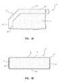
- FIG. 1is a perspective view of an exemplary superabrasive element 10 according to at least one embodiment.
- superabrasive element 10may comprise a layer or table 14 affixed to or formed upon a substrate 12 .
- Superabrasive element 10may comprise a rear face 18 and a substrate side surface 16 formed by substrate 12 .
- Superabrasive element 10may also comprise a superabrasive face 20 and a superabrasive side surface 22 formed by table 14 .
- Superabrasive table 14may be affixed to substrate 12 at interface 26 .
- Substrate 12may comprise any suitable material on which table 14 may be formed.
- substrate 12may comprise a cemented carbide material, such as a cobalt-cemented tungsten carbide material or any other suitable material.
- substrate 12may include a suitable metal-solvent catalyst material, such as, for example, cobalt, nickel, iron, and/or alloys thereof.
- substrate 12may include any suitable material including, without limitation, cemented carbides such as titanium carbide, niobium carbide, tantalum carbide, vanadium carbide, and/or combinations of any of the preceding carbides cemented with iron, nickel, cobalt, and/or alloys thereof.
- Table 14may be formed of any suitable superabrasive and/or superhard material or combination of materials, including, for example PCD. According to additional embodiments, table 14 may comprise cubic boron nitride, silicon carbide, diamond, and/or mixtures or composites including one or more of the foregoing materials.
- Table 14may be formed using any suitable technique.
- table 14may comprise a PCD layer formed by subjecting a plurality of diamond particles (e.g., diamond particles having an average particle size between approximately 0.5 ⁇ m and approximately 150 ⁇ m) to a HPHT sintering process in the presence of a metal-solvent catalyst, such as cobalt, nickel, iron, and/or any other suitable group VIII element.
- a metal-solvent catalystsuch as cobalt, nickel, iron, and/or any other suitable group VIII element.
- adjacent diamond grains in a mass of diamond particlesmay become bonded to one another, forming a PCD table comprising bonded diamond grains.
- diamond grains in table 14may have an average grain size of approximately 20 ⁇ m or less. Additionally, during a HPHT sintering process, diamond grains may become bonded to an adjacent substrate 12 at interface 26 .
- table 14may be formed by placing diamond particles adjacent to a substrate 12 comprising cemented tungsten carbide.
- the resulting sintered PCD layermay include tungsten and/or tungsten carbide.
- tungsten and/or tungsten carbidemay be swept into the PCD layer from substrate 12 during HPHT sintering.
- a liquefied metal-solvent catalyst from substrate 12e.g., cobalt from a cobalt-cemented tungsten carbide substrate
- tungsten and/or tungsten carbide particlesmay be intentionally mixed with diamond particles prior to forming table 14 .
- FIG. 2is a perspective view of an exemplary superabrasive disc 28 according to at least one embodiment.
- superabrasive disc 28may comprise a superabrasive table 14 that is not attached to a substrate.
- Superabrasive disc 28may be formed using any suitable technique, including, for example, HPHT sintering, as described above.
- superabrasive disc 28may be created by first forming a superabrasive element 10 that includes a substrate 12 and a superabrasive table 14 , as detailed above in reference to FIG. 1 . Once superabrasive element 10 has been produced, superabrasive table 14 may be separated from substrate 12 to form superabrasive disc 28 .
- superabrasive table 14may be separated from substrate 12 using a lapping process, a grinding process, a wire-electrical-discharge machining (“wire EDM”) process, or any other suitable material-removal process, without limitation.
- wire EDMwire-electrical-discharge machining
- FIG. 3Ais a cross-sectional side view of a portion of an exemplary superabrasive table 14 , such as the superabrasive tables 14 illustrated in FIGS. 1 and 2 .
- Superabrasive table 14may comprise a composite material, such as a PCD material.
- a PCD materialmay include a matrix of bonded diamond grains and interstitial regions defined between the bonded diamond grains. Such interstitial regions may be at least partially filled with various materials.
- a metal-solvent catalystmay be disposed in interstitial regions in superabrasive table 14 . Tungsten and/or tungsten carbide may also be present in the interstitial regions.
- materialsmay be deposited in interstitial regions during processing of superabrasive table 14 .
- material components of substrate 12may migrate into a mass of diamond particles used to form a superabrasive table 14 during HPHT sintering.
- a metal-solvent catalystmay melt and flow from substrate 12 into the mass of diamond particles.
- the metal-solventflows into superabrasive table 14 , it may dissolve and/or carry additional materials, such as tungsten and/or tungsten carbide, from substrate 12 into the mass of diamond particles.
- the metal-solvent catalystAs the metal-solvent catalyst flows into the mass of diamond particles, the metal-solvent catalyst, and any dissolved and/or undissolved materials, may at least partially fill spaces between the diamond particles.
- the metal-solvent catalystmay facilitate bonding of adjacent diamond particles to form a PCD layer. Following sintering, any materials, such as, for example, the metal-solvent catalyst, tungsten, and/or tungsten carbide, may remain in interstitial regions within superabrasive table 14 .
- a metal-solvent catalystsuch as cobalt
- tungsten and/or tungsten carbidemay be removed from at least a portion of superabrasive table 14 .
- a metal-solvent catalyst, as well as other materials,may be removed from superabrasive table 14 using any suitable means, without limitation.
- chemical leachingmay be used to remove a metal-solvent catalyst from superabrasive table 14 up to a depth D from a surface of superabrasive table 14 , as illustrated in FIG. 3A .
- depth Dmay be measured relative to an external surface of superabrasive table 14 , such as superabrasive face 20 , superabrasive side surface 22 , and/or superabrasive edge 24 .
- a metal-solvent catalystmay be removed from superabrasive table 14 up to a depth D of approximately 2500 ⁇ m.
- a metal-solvent catalystmay be removed from superabrasive table 14 up to a depth D of between approximately 100 and 1000 ⁇ m.
- superabrasive table 14may comprise a first volume 30 that is substantially free of a metal-solvent catalyst. However, small amounts of catalyst may remain within interstices that are inaccessible to the leaching process.
- First volume 30may extend from one or more surfaces of superabrasive table 14 (e.g., superabrasive face 20 , superabrasive side surface 22 , and/or superabrasive edge 24 ) to a depth D from the one or more surfaces.
- First volume 30may be located adjacent one or more surfaces of superabrasive table 14 .
- superabrasive tablemay also comprise a second volume 31 that contains a metal-solvent catalyst.
- An amount of metal-solvent catalyst in second volume 31may be substantially the same prior to and following leaching.
- second volume 31may be remote from one or more exposed surfaces of superabrasive table 14 .
- an amount of metal-solvent catalyst in first volume 30 and/or second volume 31may vary at different depths in superabrasive table 14 .
- superabrasive table 14may include a transition region 29 between first volume 30 and second volume 31 .
- Transition region 29may include amounts of metal-solvent catalyst varying between an amount of metal-solvent catalyst in first volume 30 and an amount of metal-solvent catalyst in second volume 31 .
- transition region 29may comprise a relatively narrow region between first volume 30 and second volume 31 .
- FIG. 3Bis a cross-sectional side view of a superabrasive disc 28 , such as the superabrasive disc 28 illustrated in FIG. 2 .
- superabrasive disc 28may comprise a superabrasive table 14 having a superabrasive face 20 , a superabrasive side surface 22 , a rear superabrasive face 23 , and superabrasive edges 24 .
- a metal-solvent catalyst, as well as other materialsmay be removed from at least a portion of superabrasive disc 28 .
- superabrasive disc 28may comprise a first volume 30 that is substantially free of a metal-solvent catalyst and a second volume 31 that contains a metal-solvent catalyst. As described above, small amounts of catalyst may remain within interstices that are inaccessible to the leaching process in first volume 30 .
- first volume 30may extend around a substantial exterior portion of superabrasive disc 28 .
- superabrasive disc 28may be submerged in a leaching solution so that superabrasive face 20 , superabrasive side surface 22 , rear superabrasive face 23 , and superabrasive edges 24 are exposed to the leaching solution, resulting in a first volume 30 that extends substantially around superabrasive disc 28 .
- only a portion of superabrasive disc 28may be exposed to a leaching solution, resulting in a first volume 30 that extends around only a portion of superabrasive disc 28 .
- FIG. 4is a magnified cross-sectional side view of a portion of the superabrasive table 14 illustrated in FIG. 3A .
- superabrasive table 14may comprise grains 32 and interstitial regions 34 between grains 32 defined by grain surfaces 36 .
- Grains 32may comprise grains formed of any suitable superabrasive material, including, for example, diamond grains. At least some of grains 32 may be bonded to one or more adjacent grains 32 , forming a polycrystalline diamond matrix.
- Interstitial material 38may be disposed in at least some of interstitial regions 34 .
- Interstitial material 38may comprise any suitable material, such as, for example, a metal-solvent catalyst, tungsten, and/or tungsten carbide. As shown in FIG. 4 , interstitial material 38 may not be present in at least some of interstitial regions 34 . At least a portion of interstitial material 38 may be removed from at least some of interstitial regions 34 during a leaching procedure. For example, a substantial portion of interstitial material 38 may be removed from first volume 30 during a leaching procedure. Additionally interstitial material 38 may remain in a second volume 31 following a leaching procedure.
- interstitial material 38may be removed from table 14 to a depth that improves the performance and heat resistance of a surface of superabrasive table 14 to a desired degree. In some embodiments, interstitial material 38 may be removed from superabrasive table 14 to a practical limit. In order to remove interstitial material 38 from superabrasive table 14 to a depth beyond the practical limit, for example, significantly more time, temperature, and/or pressure may be required. In some embodiments, interstitial material 38 may be removed from superabrasive table 14 to a practical limit where interstitial material remains in at least a portion of superabrasive table 14 . In various embodiments, superabrasive table 14 may be fully leached so that interstitial material 38 is substantially removed from a substantial portion of superabrasive table 14 .
- interstitial material 38may be leached from a superabrasive material, such as a PCD material in superabrasive table 14 , by exposing the superabrasive material to a suitable leaching solution.
- Interstitial material 38may include a metal-solvent catalyst, such as cobalt. Relatively less concentrated and/or corrosive solutions may be inhibited from leaching a PCD article to a sufficient depth due to the formation of passive tungsten oxide films in the PCD material as tungsten in the PCD material oxidizes. Oxygen present in various solutions may facilitate the formation of tungsten oxides, examples of which include WO 2 , W 2 O 5 , and WO 3 .
- the tungsten oxide filmsmay inhibit dissolution of metal-solvent catalysts present in PCD materials, potentially slowing and hindering leaching of the PCD materials. Additionally, the tungsten oxide films may form a barrier that inhibits penetration of solutions beyond a certain depth into the PCD materials.
- a suitable leaching solutionmay inhibit or prevent formation of oxide compounds, such as tungsten oxides, thereby potentially facilitating leaching of PCD materials.
- a leaching solutionmay comprise a solvent, a complexing agent, and a mineral acid.
- the superabrasive materialmay be exposed to such a leaching solution in any suitable manner, including, for example, by immersing at least a portion of the superabrasive material in the leaching solution.
- the solvent in such a leaching solutionmay comprise water and/or any other suitable solvent, without limitation.
- the leaching solutionmay also include a peroxide, such as hydrogen peroxide.
- the leaching solutionmay comprise a mineral acid suitable for increasing the solubility of a metal-solvent catalyst with respect to the leaching solution.
- the mineral acidmay be selected for its ability to attack and/or dissolve the metal-solvent catalyst.
- the leaching solutionmay then carry the dissolved metal-solvent catalyst out of a PCD material comprising the metal-solvent catalyst.
- a suitable mineral acidmay be configured to increase the solubility of the cobalt in the leaching mixture, thereby facilitating leaching of cobalt from a superabrasive material using the leaching mixture.
- a mineral acidmay be configured to increase the solubility of iron and/or nickel in the leaching mixture.
- nitric acidmay be used as a mineral acid in the leaching solution.
- a mineral acidsuch as nitric acid, may also react with amorphous carbon present in interstitial regions 34 between diamond grains 32 in a superabrasive table 14 comprising a PCD material.
- suitable mineral acidsmay include, for example, hydrochloric acid, sulfuric acid, boric acid, hydrofluoric acid, and/or any combination of the foregoing mineral acids.
- a mineral acidmay be present in the leaching solution at a molar concentration of between approximately 0.1 M and approximately 3 M. In some examples, a mineral acid may be present in the leaching solution at a molar concentration of between approximately 1 M and approximately 2 M. In at least one example, a mineral acid may be present in the leaching solution at a molar concentration of approximately 1.5 M.
- the leaching solutionmay additionally comprise a complexing agent dissolved in the solvent.
- the complexing agentmay comprise a compound suitable for forming metal complexes with tungsten and/or tungsten carbide.
- the complexing agentmay form metal complexes with tungsten and/or tungsten carbide present in a superabrasive material, thereby inhibiting or preventing the formation and build up of tungsten oxides, such as WO 2 , W 2 O 5 , and WO 3 , in the superabrasive material.
- metal complexes formed using the complexing agentmay comprise a tungsten atom and between two and four ligands.
- the complexing agentmay comprise phosphoric acid.
- the phosphoric acidmay at least partially dissociate in the leaching solution into various phosphate ions, such as, for example, dihydrogen phosphate, hydrogen phosphate, and/or orthophosphate.
- the phosphate ionsmay act as ligands in the metal complexes.
- phosphate ligandsmay bond with a tungsten atom to form a metal complex comprising the tungsten atom and between two and four phosphate ligands surrounding the tungsten atom.
- the metal complexesmay at least partially passivate the tungsten atom, inhibiting oxidation of the tungsten atom. Accordingly, the metal complexes may inhibit the formation of tungsten oxide films.
- Metal complexes formed between the complexing agent and tungsten and/or tungsten carbidemay be soluble in the leaching solution, thereby enabling the metal complexes to be easily removed from the superabrasive material. Accordingly, the complexing agent may facilitate the removal of tungsten and/or tungsten carbide from a leached portion of a superabrasive material, thereby reducing the amount of residual tungsten, tungsten carbide, and/or tungsten oxide present in a leached region of the superabrasive material. The complexing agent may also facilitate removal of additional metal compounds that may be present in the superabrasive material.
- the complexing agentmay enable the leaching solution to dissolve and remove a metal-solvent catalyst from a greater portion of a superabrasive material in comparison with leaching solutions that do not include a complexing agent. Additionally, the complexing agent may enable a metal-solvent catalyst to be removed from a greater portion of a superabrasive material in a relatively shorter period of time. The complexing agent may also enable a metal-solvent catalyst to be leached from a superabrasive material using a less corrosive acid solution in comparison with conventional leaching solutions. Further, the leaching solution comprising the complexing agent may provide more uniform leaching of the superabrasive material.
- the complexing agentmay comprise a chelating agent.
- the complexing agentmay comprise a phosphate.
- the complexing agentmay comprise a weak acid having an acid dissociation constant (pK a ) of between approximately ⁇ 2 and 12.
- pK aacid dissociation constant
- phosphoric acidmay be used as the complexing agent.
- suitable compounds that may be used as complexing agentsinclude, without limitation, citric acid, tartaric acid, oxalic acid, ammonium chloride, and/or any combination of the foregoing.
- a complexing agentmay be present in the leaching solution at a molar concentration of between approximately 0.01 M and approximately 3 M. In some examples, a complexing agent may be present in the leaching solution at a molar concentration of between approximately 0.05 M and approximately 0.5 M. In at least one example, a complexing agent may be present in the leaching solution at a molar concentration of approximately 0.125M.
- a superabrasive materialmay be exposed to the leaching solution at an elevated temperature and/or pressure. Exposing the superabrasive material to an elevated temperature and/or pressure during leaching may increase the depth to which the superabrasive material may be leached. Additionally, exposing the superabrasive material to an elevated temperature and/or pressure during leaching may decrease an amount of time required to leach the superabrasive material to a desired degree.
- At least a portion of a superabrasive material and the leaching solutionmay be exposed to a temperature of between approximately 25° C. and approximately 280° C. during leaching. According to additional embodiments, at least a portion of a superabrasive material and the leaching solution may be exposed to a temperature of between approximately 60° C. and approximately 240° C. during leaching. A leaching solution comprising a relatively higher amount of hydrogen peroxide may be exposed to a temperature of approximately 80° C. or less.
- At least a portion of a superabrasive material and a leaching solutionmay be exposed to a pressure of between approximately 0 bar and approximately 100 bar during leaching. In additional embodiments, at least a portion of a superabrasive material and a leaching solution may be exposed to a pressure of between approximately 20 bar and approximately 80 bar during leaching. In at least one example, at least a portion of a superabrasive material and a leaching solution may be exposed to a pressure of approximately 50 bar during leaching.
- At least a portion of a superabrasive material and a leaching solutionmay be exposed to at least one of an electric current, microwave radiation, and/or ultrasonic energy.
- an electric current, microwave radiation, and/or ultrasonic energyBy exposing at least a portion of a superabrasive material to an electric current, microwave radiation, and/or ultrasonic energy as the superabrasive material is exposed to a leaching solution, the rate at which the superabrasive material is leached may be increased.
- FIG. 5is a cross-sectional side view of an exemplary superabrasive element 10 that is at least partially surrounded by a protective layer 40 according to at least one embodiment.
- a protective layer 40may comprise an inert cup.
- Protective layer 40may prevent a leaching solution from chemically damaging certain portions of superabrasive element 10 , such as, for example, substrate 12 , a portion of superabrasive table 14 , or both, during leaching.
- Protective layer 40may be selectively formed over substrate 12 and a selected portion of superabrasive table 14 in any pattern, design, or as otherwise desired, without limitation. Such a configuration may provide selective leaching of superabrasive table 14 , which may be beneficial. Following leaching of superabrasive table 14 , protective layer 40 may be removed from superabrasive element 10 .
- FIGS. 6 and 7are a perspective view and a top view, respectively, of an exemplary drill bit 42 according to at least one embodiment.
- Drill bit 42may represent any type or form of earth-boring or drilling tool, including, for example, a rotary drill bit.
- drill bit 42may comprise a bit body 44 having a longitudinal axis 52 .
- Bit body 44may define a leading end structure for drilling into a subterranean formation by rotating bit body 44 about longitudinal axis 52 and applying weight to bit body 44 .
- Bit body 44may include radially and longitudinally extending blades 46 with leading faces 48 and a threaded pin connection 50 for connecting bit body 44 to a drill string.
- At least one cutting element 58may be coupled to bit body 44 .
- a plurality of cutting elements 58may be coupled to blades 46 .
- Cutting elements 58may comprise any suitable superabrasive cutting elements, without limitation.
- cutting elements 58may be configured according to previously described superabrasive element 10 and/or superabrasive disc 28 .
- each cutting element 58may include a superabrasive table 60 , such as a PCD table, bonded to a substrate 62 .
- Circumferentially adjacent blades 46may define so-called junk slots 54 therebetween.
- Junk slots 54may be configured to channel debris, such as rock or formation cuttings, away from cutting elements 58 during drilling.
- Rotary drill bit 42may also include a plurality of nozzle cavities 56 for communicating drilling fluid from the interior of rotary drill bit 42 to cutting elements 58 .
- FIGS. 6 and 7depict an example of a rotary drill bit 42 that employs at least one cutting element 58 comprising a superabrasive table 60 fabricated and structured in accordance with the disclosed embodiments, without limitation.
- Rotary drill bit 42may additionally represent any number of earth-boring tools or drilling tools, including, for example, core bits, roller-cone bits, fixed-cutter bits, eccentric bits, bicenter bits, reamers, reamer wings, or any other downhole tool including superabrasive cutting elements and discs, without limitation.
- superabrasive elements and discs disclosed hereinmay also be utilized in applications other than cutting technology.
- embodiments of superabrasive elements disclosed hereinmay also form all or part of heat sinks, wire dies, bearing elements, cutting elements, cutting inserts (e.g., on a roller cone type drill bit), machining inserts, or any other article of manufacture as known in the art.
- superabrasive elements and discs, as disclosed hereinmay be employed in any suitable article of manufacture that includes a superabrasive element, disc, or layer.
- Other examples of articles of manufacture that may incorporate superabrasive elements as disclosed hereinmay be found in U.S. Pat. Nos.
- a rotor and a statormay each include at least one superabrasive element according to the embodiments disclosed herein.
- a rotor and a statormay each include at least one superabrasive element according to the embodiments disclosed herein.
- U.S. Pat. Nos. 4,410,054; 4,560,014; 5,364,192; 5,368,398; and 5,480,233disclose subterranean drilling systems that include bearing apparatuses utilizing superabrasive elements as disclosed herein.
- FIG. 8is partial cross-sectional perspective view of an exemplary thrust-bearing apparatus 64 according to at least one embodiment.
- Thrust-bearing apparatus 64may utilize any of the disclosed superabrasive element embodiments as bearing elements 70 .
- Thrust-bearing apparatus 64may also include bearing assemblies 66 .
- Each bearing assembly 66may include a support ring 68 fabricated from a material, such as steel, stainless steel, or any other suitable material, without limitation.
- Each support ring 68may include a plurality of recesses 69 configured to receive corresponding bearing elements 70 .
- Each bearing element 70may be mounted to a corresponding support ring 68 within a corresponding recess 69 by brazing, welding, press-fitting, using fasteners, or any another suitable mounting technique, without limitation.
- One or more of bearing elements 70may be configured in accordance with any of the disclosed superabrasive element embodiments.
- each bearing element 70may include a substrate 72 and a superabrasive table 74 comprising a PCD material.
- Each superabrasive table 74may form a bearing surface 76 .
- Bearing surfaces 76 of one bearing assembly 66may bear against opposing bearing surfaces 76 of a corresponding bearing assembly 66 in thrust-bearing apparatus 64 , as illustrated in FIG. 8 .
- a first bearing assembly 66 of thrust-bearing apparatus 64may be termed a “rotor.”
- the rotormay be operably coupled to a rotational shaft.
- a second bearing assembly 66 of thrust-bearing apparatus 64may be held substantially stationary relative to the first bearing assembly 66 and may be termed a “stator.”
- FIG. 9is a perspective view of a radial bearing apparatus 78 according to another embodiment.
- Radial bearing apparatus 78may utilize any of the disclosed superabrasive element embodiments as bearing elements 84 and 86 .
- Radial bearing apparatus 78may include an inner race 80 positioned generally within an outer race 82 .
- Inner race 80may include a plurality of bearing elements 84 affixed thereto, and outer race 80 may include a plurality of corresponding bearing elements 86 affixed thereto.
- One or more of bearing elements 84 and 86may be configured in accordance with any of the superabrasive element embodiments disclosed herein.
- Inner race 80may be positioned generally within outer race 82 .
- inner race 80 and outer race 82may be configured such that bearing surfaces 85 defined by bearing elements 84 and bearing surfaces 87 defined by bearing elements 86 may at least partially contact one another and move relative to one another as inner race 80 and outer race 82 rotate relative to each other.
- thrust-bearing apparatus 64 and/or radial bearing apparatus 78may be incorporated into a subterranean drilling system.
- FIG. 10is a partial cross-sectional perspective view of an exemplary subterranean drilling system 88 that includes a thrust-bearing apparatus 64 , as shown in FIG. 8 , according to at least one embodiment.
- the subterranean drilling system 88may include a housing 90 enclosing a downhole drilling motor 92 (i.e., a motor, turbine, or any other suitable device capable of rotating an output shaft, without limitation) that is operably connected to an output shaft 94 .
- a downhole drilling motor 92i.e., a motor, turbine, or any other suitable device capable of rotating an output shaft, without limitation
- the thrust-bearing apparatus 64 shown in FIG. 10may be operably coupled to downhole drilling motor 92 .
- a rotary drill bit 96such as a rotary drill bit configured to engage a subterranean formation and drill a borehole, may be connected to output shaft 94 .
- rotary drill bit 96may be a roller cone bit comprising a plurality of roller cones 98 .
- rotary drill bit 96may comprise any suitable type of rotary drill bit, such as, for example, a so-called fixed-cutter drill bit.
- pipe sectionsmay be connected to subterranean drilling system 88 to form a drill string capable of progressively drilling the borehole to a greater depth within a subterranean formation.
- a first thrust-bearing assembly 66 in thrust-bearing apparatus 64may be configured as a rotor that is attached to output shaft 94 and a second thrust-bearing assembly 66 in thrust-bearing apparatus 64 may be configured as a stator.
- the rotormay rotate in conjunction with output shaft 94 and the stator may remain substantially stationary relative to the rotor.
- drilling fluidmay be circulated through downhole drilling motor 92 to generate torque and effect rotation of output shaft 94 and rotary drill bit 96 attached thereto so that a borehole may be drilled.
- a portion of the drilling fluidmay also be used to lubricate opposing bearing surfaces of bearing elements 70 on thrust-bearing assemblies 66 .
- FIG. 11illustrates an exemplary method 100 of processing a polycrystalline diamond material according to at least one embodiment.
- a metal-solvent catalystmay be leached from a polycrystalline diamond material by exposing at least a portion of the polycrystalline diamond material to a leaching solution (step 102 ).
- the leaching solutionmay include a solvent, a complexing agent, and a mineral acid.
- the solventmay comprise water.
- the complexing agentmay be configured to inhibit tungsten in the polycrystalline diamond material from oxidizing.
- Each of the complexing agent and the mineral acidmay be dissolved in the solvent.
- the polycrystalline diamond materialmay be exposed to the leaching solution in any suitable manner, such as, for example, by submerging at least a portion of the polycrystalline diamond material in the leaching solution.
- a polycrystalline diamond materialmay comprise at least a portion of any suitable polycrystalline diamond article.
- the polycrystalline materialmay comprise a PCD table attached to a tungsten carbide substrate in a superabrasive element or a superabrasive disc (e.g., superabrasive element 10 and superabrasive disc 28 in FIGS. 1 and 2 , respectively).
- the polycrystalline diamond materialmay include bonded diamond grains and interstitial regions between the bonded diamond grains (e.g., grains 32 and interstitial regions 34 in FIG. 4 ).
- tungsten, tungsten carbide, and/or a metal-solvent catalystsuch as cobalt, nickel, iron, and/or any suitable group VIII element, may be disposed in at least some of the interstitial regions between the bonded diamond grains.
- the leaching solutionmay remove at least a portion of a metal-solvent catalyst, tungsten, and/or tungsten carbide from the polycrystalline diamond material to form a volume in the polycrystalline diamond material from which a metal-solvent catalyst has been substantially removed (e.g., first volume 30 in FIG. 3A ).
- FIG. 12illustrates an exemplary method 110 of processing a polycrystalline diamond material according to additional embodiments.
- a metal-solvent catalystmay be leached from a polycrystalline diamond material by exposing at least a portion of the polycrystalline diamond material to a leaching solution (step 112 ).
- the leaching solutionmay include a solvent, a complexing agent, and a mineral acid.
- At least a portion of the polycrystalline diamond and the leaching solution materialmay be exposed to a temperature of between approximately 25° C. and approximately 280° C. (step 114 ). Additionally, at least a portion of the polycrystalline diamond material and the leaching solution may be exposed to a pressure of between approximately 20 bar and approximately 100 bar (step 116 ).
- the polycrystalline diamond materialmay be separated from the leaching solution (step 118 ). For example, a polycrystalline diamond material that is submerged in a leaching solution may be removed from the leaching solution. Additionally, the leaching solution may be at least partially washed from the polycrystalline diamond material.
- FIG. 13illustrates an exemplary method 120 of processing a polycrystalline diamond material according to various embodiments.
- a cutting elementhaving a substrate and a polycrystalline diamond table bonded to the substrate may be provided (step 122 ).
- the polycrystalline diamond tablemay include tungsten and a metal-solvent catalyst.
- the tungstenmay be present in the form of elemental tungsten and/or tungsten carbide.
- the polycrystalline diamond tablemay include a metal-solvent catalyst, including, for example, cobalt, iron, nickel, and/or any other suitable group VIII element.
- At least a portion of the metal-solvent catalystmay be leached from the polycrystalline diamond table by exposing at least a portion of the polycrystalline diamond table to a leaching solution (step 124 ).
- the leaching solutionmay include a solvent, a complexing agent, and a mineral acid.
- FIG. 14illustrates an exemplary method 130 of processing a polycrystalline diamond material according to certain embodiments.
- a polycrystalline diamond materialincluding bonded diamond grains, tungsten, and a metal-solvent catalyst may be provided (step 132 ).
- Metal complexesmay be formed within the polycrystalline diamond material (step 134 ).
- the metal complexesmay include at least a portion of the tungsten from the polycrystalline diamond material and a complexing agent.
- the tungstenmay be present in the form of elemental tungsten and/or tungsten carbide.
- At least a portion of the metal-solvent catalystmay be dissolved in a mineral acid solution (step 136 ).
- the dissolved metal-solvent catalystmay then be extracted from the polycrystalline diamond material (step 138 ).
- the metal-solvent catalyst dissolved in the mineral acid solutionmay be transported away from the polycrystalline diamond material by the mineral acid solution.
- Cutting elementseach comprising a PCD table attached to a tungsten carbide substrate, were formed by HPHT sintering diamond particles having an average grain size of about 10 ⁇ m in the presence of cobalt.
- the sintered-polycrystalline-diamond tablesincluded cobalt and tungsten within the interstitial regions between the bonded diamond grains.
- the PCD tableswere leached using a solution having a molar concentration of 1.5 M nitric acid and 0.125 M phosphoric acid.
- the PCD tableswere leached at a temperature of 60° C. and atmospheric pressure for between 1 and 5 days.
- leached depths of the PCD tableswere determined for various portions of the PCD tables, including leached depths measured from the cutting faces, side surfaces, and chamfered cutting edges of the PCD tables.
- a first PCD tableincluded leached depths of 81-118 ⁇ m and a second PCD table included leached depths of 107-133 ⁇ m.
- a first PCD tableincluded leached depths of 145-169 ⁇ m and a second PCD table included leached depths of 140-179 ⁇ m.
- a first PCD tableincluded leached depths of 199-234 ⁇ m and a second PCD table included leached depths of 190-215 ⁇ m.
- a first PCD tableincluded leached depths of 215-259 ⁇ m and a second PCD table included leached depths of 198-245 ⁇ m.
- a first PCD tableincluded leached depths of 237-303 ⁇ m and a second PCD table included leached depths of 238-286 ⁇ m.
- Cutting elementseach comprising a PCD table attached to a tungsten carbide substrate, were formed by HPHT sintering diamond particles having an average grain size of about 10 ⁇ m in the presence of cobalt.
- the sintered-polycrystalline-diamond tablesincluded cobalt and tungsten within the interstitial regions between the bonded diamond grains.
- the PCD tableswere leached using a solution having a molar concentration of 1.5 M nitric acid and 0.125 M phosphoric acid.
- the PCD tableswere leached at a temperature of 75° C. and atmospheric pressure for between 1 and 2 days.
- leached depths of the PCD tableswere determined for various portions of the PCD tables, including leached depths measured from the cutting faces, side surfaces, and chamfered cutting edges of the PCD tables.
- a PCD tableincluded leached depths of 105-156 ⁇ m. Following 2 days of leaching, a PCD table included leached depths of 193-238 ⁇ m.
- a cutting elementcomprising a PCD table attached to a tungsten carbide substrate was formed by HPHT sintering diamond particles having an average grain size of about 10 ⁇ m in the presence of cobalt.
- the sintered-polycrystalline-diamond tableincluded cobalt and tungsten within the interstitial regions between the bonded diamond grains.
- the PCD tablewas leached using a solution having a molar concentration of 1.5 M nitric acid and 0.125 M phosphoric acid.
- the PCD tablewas leached at a temperature of 120° C. and atmospheric pressure for 5 days.
- leached depths of the PCD tablewere determined for various portions of the PCD table, including leached depths measured from the table cutting face, side surfaces, and chamfered cutting edges of the PCD table. Following 5 days of leaching, the PCD table included leached depths of 160-585 ⁇ m.
Landscapes
- Chemical & Material Sciences (AREA)
- Engineering & Computer Science (AREA)
- Materials Engineering (AREA)
- Ceramic Engineering (AREA)
- Organic Chemistry (AREA)
- Structural Engineering (AREA)
- Mechanical Engineering (AREA)
- Metallurgy (AREA)
- Manufacturing & Machinery (AREA)
- Chemical Kinetics & Catalysis (AREA)
- General Chemical & Material Sciences (AREA)
- Polishing Bodies And Polishing Tools (AREA)
Abstract
Description
Claims (21)
Priority Applications (2)
| Application Number | Priority Date | Filing Date | Title |
|---|---|---|---|
| US13/114,599US8377157B1 (en) | 2009-04-06 | 2011-05-24 | Superabrasive articles and methods for removing interstitial materials from superabrasive materials |
| US13/736,025US8741005B1 (en) | 2009-04-06 | 2013-01-07 | Superabrasive articles and methods for removing interstitial materials from superabrasive materials |
Applications Claiming Priority (2)
| Application Number | Priority Date | Filing Date | Title |
|---|---|---|---|
| US12/419,191US7972395B1 (en) | 2009-04-06 | 2009-04-06 | Superabrasive articles and methods for removing interstitial materials from superabrasive materials |
| US13/114,599US8377157B1 (en) | 2009-04-06 | 2011-05-24 | Superabrasive articles and methods for removing interstitial materials from superabrasive materials |
Related Parent Applications (1)
| Application Number | Title | Priority Date | Filing Date |
|---|---|---|---|
| US12/419,191ContinuationUS7972395B1 (en) | 2009-04-06 | 2009-04-06 | Superabrasive articles and methods for removing interstitial materials from superabrasive materials |
Related Child Applications (1)
| Application Number | Title | Priority Date | Filing Date |
|---|---|---|---|
| US13/736,025ContinuationUS8741005B1 (en) | 2009-04-06 | 2013-01-07 | Superabrasive articles and methods for removing interstitial materials from superabrasive materials |
Publications (1)
| Publication Number | Publication Date |
|---|---|
| US8377157B1true US8377157B1 (en) | 2013-02-19 |
Family
ID=44202375
Family Applications (3)
| Application Number | Title | Priority Date | Filing Date |
|---|---|---|---|
| US12/419,191Active2029-07-17US7972395B1 (en) | 2009-04-06 | 2009-04-06 | Superabrasive articles and methods for removing interstitial materials from superabrasive materials |
| US13/114,599ActiveUS8377157B1 (en) | 2009-04-06 | 2011-05-24 | Superabrasive articles and methods for removing interstitial materials from superabrasive materials |
| US13/736,025ActiveUS8741005B1 (en) | 2009-04-06 | 2013-01-07 | Superabrasive articles and methods for removing interstitial materials from superabrasive materials |
Family Applications Before (1)
| Application Number | Title | Priority Date | Filing Date |
|---|---|---|---|
| US12/419,191Active2029-07-17US7972395B1 (en) | 2009-04-06 | 2009-04-06 | Superabrasive articles and methods for removing interstitial materials from superabrasive materials |
Family Applications After (1)
| Application Number | Title | Priority Date | Filing Date |
|---|---|---|---|
| US13/736,025ActiveUS8741005B1 (en) | 2009-04-06 | 2013-01-07 | Superabrasive articles and methods for removing interstitial materials from superabrasive materials |
Country Status (1)
| Country | Link |
|---|---|
| US (3) | US7972395B1 (en) |
Cited By (3)
| Publication number | Priority date | Publication date | Assignee | Title |
|---|---|---|---|---|
| US20120055717A1 (en)* | 2009-03-06 | 2012-03-08 | John Hewitt Liversage | Polycrystalline diamond element |
| WO2015030966A3 (en)* | 2013-08-26 | 2015-06-04 | Eve Jonathan M | Methods and systems for removing diamond-diamond bonding catalysts from polycrystalline diamond |
| WO2025128143A1 (en)* | 2023-12-11 | 2025-06-19 | CNPC USA Corp. | A pdc cutter and method of making it |
Families Citing this family (17)
| Publication number | Priority date | Publication date | Assignee | Title |
|---|---|---|---|---|
| US8435324B2 (en)* | 2010-12-21 | 2013-05-07 | Halliburton Energy Sevices, Inc. | Chemical agents for leaching polycrystalline diamond elements |
| US12194600B1 (en) | 2011-08-15 | 2025-01-14 | Us Synthetic Corporation | Methods of processing a polycrystalline diamond element |
| US9844854B1 (en)* | 2012-11-21 | 2017-12-19 | Us Synthetic Corporation | Protective leaching cups, systems, and methods of use |
| GB201122415D0 (en)* | 2011-12-29 | 2012-02-08 | Element Six Abrasives Sa | Method of processing a body of polycrystalline diamond material |
| GB201122434D0 (en)* | 2011-12-29 | 2012-02-08 | Element Six Abrasives Sa | Method of processing polycrystalline diamond material |
| GB2507566A (en)* | 2012-11-05 | 2014-05-07 | Element Six Abrasives Sa | Tool with a PCD body |
| US9156136B2 (en) | 2012-11-07 | 2015-10-13 | National Oilwell Varco, L.P. | Systems and methods for vapor pressure leaching polycrystalline diamond cutter elements |
| GB2528786B (en) | 2012-12-31 | 2018-03-28 | Nat Oilwell Varco Lp | Apparatus and methods for high pressure leaching of polycrystalline diamond cutter elements |
| US10718166B2 (en) | 2014-06-20 | 2020-07-21 | Halliburton Energy Services, Inc. | Laser-leached polycrystalline diamond and laser-leaching methods and devices |
| US9908215B1 (en) | 2014-08-12 | 2018-03-06 | Us Synthetic Corporation | Systems, methods and assemblies for processing superabrasive materials |
| US9840876B2 (en) | 2014-10-06 | 2017-12-12 | CNPC USA Corp. | Polycrystalline diamond compact cutter |
| US11766761B1 (en) | 2014-10-10 | 2023-09-26 | Us Synthetic Corporation | Group II metal salts in electrolytic leaching of superabrasive materials |
| US10011000B1 (en) | 2014-10-10 | 2018-07-03 | Us Synthetic Corporation | Leached superabrasive elements and systems, methods and assemblies for processing superabrasive materials |
| US10723626B1 (en) | 2015-05-31 | 2020-07-28 | Us Synthetic Corporation | Leached superabrasive elements and systems, methods and assemblies for processing superabrasive materials |
| US9931714B2 (en) | 2015-09-11 | 2018-04-03 | Baker Hughes, A Ge Company, Llc | Methods and systems for removing interstitial material from superabrasive materials of cutting elements using energy beams |
| US20190257208A1 (en)* | 2018-02-20 | 2019-08-22 | Novatek Ip, Llc | Unitary Turbine Blade and Method of Manufacture Thereof |
| US12168281B2 (en)* | 2022-01-11 | 2024-12-17 | Baker Hughes Oilfield Operations Llc | Polycrystalline diamond compact cutting elements, methods of forming same and earth-boring tools |
Citations (148)
| Publication number | Priority date | Publication date | Assignee | Title |
|---|---|---|---|---|
| US3136615A (en) | 1960-10-03 | 1964-06-09 | Gen Electric | Compact of abrasive crystalline material with boron carbide bonding medium |
| US3141746A (en) | 1960-10-03 | 1964-07-21 | Gen Electric | Diamond compact abrasive |
| US3233988A (en) | 1964-05-19 | 1966-02-08 | Gen Electric | Cubic boron nitride compact and method for its production |
| US3745623A (en) | 1971-12-27 | 1973-07-17 | Gen Electric | Diamond tools for machining |
| GB1349385A (en) | 1970-04-08 | 1974-04-03 | Gen Electric | Diamond tools for machining |
| US4108614A (en) | 1976-04-14 | 1978-08-22 | Robert Dennis Mitchell | Zirconium layer for bonding diamond compact to cemented carbide backing |
| US4151686A (en) | 1978-01-09 | 1979-05-01 | General Electric Company | Silicon carbide and silicon bonded polycrystalline diamond body and method of making it |
| US4224380A (en) | 1978-03-28 | 1980-09-23 | General Electric Company | Temperature resistant abrasive compact and method for making same |
| US4255165A (en) | 1978-12-22 | 1981-03-10 | General Electric Company | Composite compact of interleaved polycrystalline particles and cemented carbide masses |
| US4268276A (en) | 1978-04-24 | 1981-05-19 | General Electric Company | Compact of boron-doped diamond and method for making same |
| US4288248A (en) | 1978-03-28 | 1981-09-08 | General Electric Company | Temperature resistant abrasive compact and method for making same |
| US4303442A (en) | 1978-08-26 | 1981-12-01 | Sumitomo Electric Industries, Ltd. | Diamond sintered body and the method for producing the same |
| US4311490A (en) | 1980-12-22 | 1982-01-19 | General Electric Company | Diamond and cubic boron nitride abrasive compacts using size selective abrasive particle layers |
| US4373593A (en) | 1979-03-16 | 1983-02-15 | Christensen, Inc. | Drill bit |
| GB2048927B (en) | 1979-03-19 | 1983-03-30 | De Beers Ind Diamond | Abrasive compacts |
| US4387287A (en) | 1978-06-29 | 1983-06-07 | Diamond S.A. | Method for a shaping of polycrystalline synthetic diamond |
| US4412980A (en) | 1979-06-11 | 1983-11-01 | Sumitomo Electric Industries, Ltd. | Method for producing a diamond sintered compact |
| US4481016A (en) | 1978-08-18 | 1984-11-06 | Campbell Nicoll A D | Method of making tool inserts and drill bits |
| US4486286A (en) | 1982-09-28 | 1984-12-04 | Nerken Research Corp. | Method of depositing a carbon film on a substrate and products obtained thereby |
| US4504519A (en) | 1981-10-21 | 1985-03-12 | Rca Corporation | Diamond-like film and process for producing same |
| US4522633A (en) | 1982-08-05 | 1985-06-11 | Dyer Henry B | Abrasive bodies |
| US4525179A (en) | 1981-07-27 | 1985-06-25 | General Electric Company | Process for making diamond and cubic boron nitride compacts |
| US4534773A (en) | 1983-01-10 | 1985-08-13 | Cornelius Phaal | Abrasive product and method for manufacturing |
| US4556403A (en) | 1983-02-08 | 1985-12-03 | Almond Eric A | Diamond abrasive products |
| US4560014A (en) | 1982-04-05 | 1985-12-24 | Smith International, Inc. | Thrust bearing assembly for a downhole drill motor |
| US4570726A (en) | 1982-10-06 | 1986-02-18 | Megadiamond Industries, Inc. | Curved contact portion on engaging elements for rotary type drag bits |
| US4572722A (en) | 1982-10-21 | 1986-02-25 | Dyer Henry B | Abrasive compacts |
| US4604106A (en) | 1984-04-16 | 1986-08-05 | Smith International Inc. | Composite polycrystalline diamond compact |
| US4605343A (en) | 1984-09-20 | 1986-08-12 | General Electric Company | Sintered polycrystalline diamond compact construction with integral heat sink |
| US4606738A (en) | 1981-04-01 | 1986-08-19 | General Electric Company | Randomly-oriented polycrystalline silicon carbide coatings for abrasive grains |
| US4621031A (en) | 1984-11-16 | 1986-11-04 | Dresser Industries, Inc. | Composite material bonded by an amorphous metal, and preparation thereof |
| US4636253A (en) | 1984-09-08 | 1987-01-13 | Sumitomo Electric Industries, Ltd. | Diamond sintered body for tools and method of manufacturing same |
| US4645977A (en) | 1984-08-31 | 1987-02-24 | Matsushita Electric Industrial Co., Ltd. | Plasma CVD apparatus and method for forming a diamond like carbon film |
| US4662348A (en) | 1985-06-20 | 1987-05-05 | Megadiamond, Inc. | Burnishing diamond |
| US4664705A (en) | 1985-07-30 | 1987-05-12 | Sii Megadiamond, Inc. | Infiltrated thermally stable polycrystalline diamond |
| US4670025A (en) | 1984-08-13 | 1987-06-02 | Pipkin Noel J | Thermally stable diamond compacts |
| US4707384A (en) | 1984-06-27 | 1987-11-17 | Santrade Limited | Method for making a composite body coated with one or more layers of inorganic materials including CVD diamond |
| US4726718A (en) | 1984-03-26 | 1988-02-23 | Eastman Christensen Co. | Multi-component cutting element using triangular, rectangular and higher order polyhedral-shaped polycrystalline diamond disks |
| US4731296A (en) | 1986-07-03 | 1988-03-15 | Mitsubishi Kinzoku Kabushiki Kaisha | Diamond-coated tungsten carbide-base sintered hard alloy material for insert of a cutting tool |
| US4766040A (en) | 1987-06-26 | 1988-08-23 | Sandvik Aktiebolag | Temperature resistant abrasive polycrystalline diamond bodies |
| US4776861A (en) | 1983-08-29 | 1988-10-11 | General Electric Company | Polycrystalline abrasive grit |
| US4784023A (en) | 1985-12-05 | 1988-11-15 | Diamant Boart-Stratabit (Usa) Inc. | Cutting element having composite formed of cemented carbide substrate and diamond layer and method of making same |
| US4792001A (en) | 1986-03-27 | 1988-12-20 | Shell Oil Company | Rotary drill bit |
| US4793828A (en) | 1984-03-30 | 1988-12-27 | Tenon Limited | Abrasive products |
| US4797241A (en) | 1985-05-20 | 1989-01-10 | Sii Megadiamond | Method for producing multiple polycrystalline bodies |
| EP0300699A2 (en) | 1987-07-24 | 1989-01-25 | Smith International, Inc. | Bearings for rock bits |
| US4802539A (en) | 1984-12-21 | 1989-02-07 | Smith International, Inc. | Polycrystalline diamond bearing system for a roller cone rock bit |
| US4807402A (en) | 1988-02-12 | 1989-02-28 | General Electric Company | Diamond and cubic boron nitride |
| US4828582A (en) | 1983-08-29 | 1989-05-09 | General Electric Company | Polycrystalline abrasive grit |
| US4844185A (en) | 1986-11-11 | 1989-07-04 | Reed Tool Company Limited | Rotary drill bits |
| US4854405A (en) | 1988-01-04 | 1989-08-08 | American National Carbide Company | Cutting tools |
| US4861350A (en) | 1985-08-22 | 1989-08-29 | Cornelius Phaal | Tool component |
| US4871377A (en) | 1986-07-30 | 1989-10-03 | Frushour Robert H | Composite abrasive compact having high thermal stability and transverse rupture strength |
| US4899922A (en) | 1988-02-22 | 1990-02-13 | General Electric Company | Brazed thermally-stable polycrystalline diamond compact workpieces and their fabrication |
| US4919220A (en) | 1984-07-19 | 1990-04-24 | Reed Tool Company, Ltd. | Cutting structures for steel bodied rotary drill bits |
| US4931068A (en) | 1988-08-29 | 1990-06-05 | Exxon Research And Engineering Company | Method for fabricating fracture-resistant diamond and diamond composite articles |
| US4940180A (en) | 1988-08-04 | 1990-07-10 | Martell Trevor J | Thermally stable diamond abrasive compact body |
| US4943488A (en) | 1986-10-20 | 1990-07-24 | Norton Company | Low pressure bonding of PCD bodies and method for drill bits and the like |
| US4944772A (en) | 1988-11-30 | 1990-07-31 | General Electric Company | Fabrication of supported polycrystalline abrasive compacts |
| US4976324A (en) | 1989-09-22 | 1990-12-11 | Baker Hughes Incorporated | Drill bit having diamond film cutting surface |
| EP0196777B1 (en) | 1985-03-01 | 1991-03-06 | Reed Tool Company Limited | Improvements in or relating to cutting elements for rotary drill bits |
| US5011514A (en) | 1988-07-29 | 1991-04-30 | Norton Company | Cemented and cemented/sintered superabrasive polycrystalline bodies and methods of manufacture thereof |
| US5027912A (en) | 1988-07-06 | 1991-07-02 | Baker Hughes Incorporated | Drill bit having improved cutter configuration |
| US5030276A (en) | 1986-10-20 | 1991-07-09 | Norton Company | Low pressure bonding of PCD bodies and method |
| US5092687A (en) | 1991-06-04 | 1992-03-03 | Anadrill, Inc. | Diamond thrust bearing and method for manufacturing same |
| US5096465A (en) | 1989-12-13 | 1992-03-17 | Norton Company | Diamond metal composite cutter and method for making same |
| US5116568A (en) | 1986-10-20 | 1992-05-26 | Norton Company | Method for low pressure bonding of PCD bodies |
| US5127923A (en) | 1985-01-10 | 1992-07-07 | U.S. Synthetic Corporation | Composite abrasive compact having high thermal stability |
| US5135061A (en) | 1989-08-04 | 1992-08-04 | Newton Jr Thomas A | Cutting elements for rotary drill bits |
| US5176720A (en) | 1989-09-14 | 1993-01-05 | Martell Trevor J | Composite abrasive compacts |
| US5186725A (en) | 1989-12-11 | 1993-02-16 | Martell Trevor J | Abrasive products |
| US5199832A (en) | 1984-03-26 | 1993-04-06 | Meskin Alexander K | Multi-component cutting element using polycrystalline diamond disks |
| US5205684A (en) | 1984-03-26 | 1993-04-27 | Eastman Christensen Company | Multi-component cutting element using consolidated rod-like polycrystalline diamond |
| US5213248A (en) | 1992-01-10 | 1993-05-25 | Norton Company | Bonding tool and its fabrication |
| US5238074A (en) | 1992-01-06 | 1993-08-24 | Baker Hughes Incorporated | Mosaic diamond drag bit cutter having a nonuniform wear pattern |
| US5264283A (en) | 1990-10-11 | 1993-11-23 | Sandvik Ab | Diamond tools for rock drilling, metal cutting and wear part applications |
| EP0585631A1 (en) | 1992-08-05 | 1994-03-09 | Takeda Chemical Industries, Ltd. | Platelet-increasing agent |
| US5337844A (en) | 1992-07-16 | 1994-08-16 | Baker Hughes, Incorporated | Drill bit having diamond film cutting elements |
| US5355969A (en) | 1993-03-22 | 1994-10-18 | U.S. Synthetic Corporation | Composite polycrystalline cutting element with improved fracture and delamination resistance |
| US5370195A (en) | 1993-09-20 | 1994-12-06 | Smith International, Inc. | Drill bit inserts enhanced with polycrystalline diamond |
| US5379853A (en) | 1993-09-20 | 1995-01-10 | Smith International, Inc. | Diamond drag bit cutting elements |
| RU2034937C1 (en) | 1991-05-22 | 1995-05-10 | Кабардино-Балкарский государственный университет | Method for electrochemical treatment of products |
| US5439492A (en) | 1992-06-11 | 1995-08-08 | General Electric Company | Fine grain diamond workpieces |
| US5464068A (en) | 1992-11-24 | 1995-11-07 | Najafi-Sani; Mohammad | Drill bits |
| US5468268A (en) | 1993-05-27 | 1995-11-21 | Tank; Klaus | Method of making an abrasive compact |
| US5496639A (en) | 1994-05-04 | 1996-03-05 | The United States Of America As Represented By The Administrator Of The National Aeronautics And Space Administration | Poly(arylene ether imidazole) surfacing films for flat and parabolic structures |
| US5505748A (en) | 1993-05-27 | 1996-04-09 | Tank; Klaus | Method of making an abrasive compact |
| US5510193A (en) | 1994-10-13 | 1996-04-23 | General Electric Company | Supported polycrystalline diamond compact having a cubic boron nitride interlayer for improved physical properties |
| US5524719A (en) | 1995-07-26 | 1996-06-11 | Dennis Tool Company | Internally reinforced polycrystalling abrasive insert |
| US5560716A (en) | 1993-03-26 | 1996-10-01 | Tank; Klaus | Bearing assembly |
| US5607024A (en) | 1995-03-07 | 1997-03-04 | Smith International, Inc. | Stability enhanced drill bit and cutting structure having zones of varying wear resistance |
| US5620302A (en) | 1995-08-31 | 1997-04-15 | Fasco Industries, Inc. | Dynamic condensate evacuator for high efficiency gas furnaces |
| US5620382A (en) | 1996-03-18 | 1997-04-15 | Hyun Sam Cho | Diamond golf club head |
| US5645617A (en) | 1995-09-06 | 1997-07-08 | Frushour; Robert H. | Composite polycrystalline diamond compact with improved impact and thermal stability |
| EP0787820A2 (en) | 1996-01-11 | 1997-08-06 | Saint-Gobain/Norton Industrial Ceramics Corporation | Methods of preparing cutting tool substrates for coating with diamond and products resulting therefrom |
| US5667028A (en) | 1995-08-22 | 1997-09-16 | Smith International, Inc. | Multiple diamond layer polycrystalline diamond composite cutters |
| EP0500253B1 (en) | 1991-02-18 | 1997-11-12 | Sumitomo Electric Industries, Limited | Diamond- or diamond-like carbon coated hard materials |
| EP0595630B1 (en) | 1992-10-28 | 1998-01-07 | Csir | Diamond bearing assembly |
| US5718948A (en) | 1990-06-15 | 1998-02-17 | Sandvik Ab | Cemented carbide body for rock drilling mineral cutting and highway engineering |
| US5722499A (en) | 1995-08-22 | 1998-03-03 | Smith International, Inc. | Multiple diamond layer polycrystalline diamond composite cutters |
| US5722497A (en) | 1996-03-21 | 1998-03-03 | Dresser Industries, Inc. | Roller cone gage surface cutting elements with multiple ultra hard cutting surfaces |
| US5759216A (en) | 1994-11-30 | 1998-06-02 | Sumitomo Electric Industries, Ltd. | Diamond sintered body having high strength and high wear-resistance and manufacturing method thereof |
| US5776615A (en) | 1992-11-09 | 1998-07-07 | Northwestern University | Superhard composite materials including compounds of carbon and nitrogen deposited on metal and metal nitride, carbide and carbonitride |
| EP0612868B1 (en) | 1993-02-22 | 1998-07-22 | Sumitomo Electric Industries, Ltd. | Single crystal diamond and process for producing the same |
| EP0860515A1 (en) | 1997-02-20 | 1998-08-26 | De Beers Industrial Diamond Division (Proprietary) Limited | Diamond-coated body |
| US5833021A (en) | 1996-03-12 | 1998-11-10 | Smith International, Inc. | Surface enhanced polycrystalline diamond composite cutters |
| US5875862A (en) | 1995-07-14 | 1999-03-02 | U.S. Synthetic Corporation | Polycrystalline diamond cutter with integral carbide/diamond transition layer |
| US5897942A (en) | 1993-10-29 | 1999-04-27 | Balzers Aktiengesellschaft | Coated body, method for its manufacturing as well as its use |
| US5954147A (en) | 1997-07-09 | 1999-09-21 | Baker Hughes Incorporated | Earth boring bits with nanocrystalline diamond enhanced elements |
| US5979578A (en) | 1997-06-05 | 1999-11-09 | Smith International, Inc. | Multi-layer, multi-grade multiple cutting surface PDC cutter |
| US6009963A (en) | 1997-01-14 | 2000-01-04 | Baker Hughes Incorporated | Superabrasive cutting element with enhanced stiffness, thermal conductivity and cutting efficiency |
| US6063333A (en) | 1996-10-15 | 2000-05-16 | Penn State Research Foundation | Method and apparatus for fabrication of cobalt alloy composite inserts |
| US6123612A (en) | 1998-04-15 | 2000-09-26 | 3M Innovative Properties Company | Corrosion resistant abrasive article and method of making |
| US6126741A (en) | 1998-12-07 | 2000-10-03 | General Electric Company | Polycrystalline carbon conversion |
| US6193001B1 (en) | 1998-03-25 | 2001-02-27 | Smith International, Inc. | Method for forming a non-uniform interface adjacent ultra hard material |
| US6234261B1 (en) | 1999-03-18 | 2001-05-22 | Camco International (Uk) Limited | Method of applying a wear-resistant layer to a surface of a downhole component |
| US6248447B1 (en) | 1999-09-03 | 2001-06-19 | Camco International (Uk) Limited | Cutting elements and methods of manufacture thereof |
| GB2323398B (en) | 1997-02-14 | 2001-06-20 | Baker Hughes Inc | Super abrasive cutting element with buttress-supported planar chamfer and drill bits so equipped |
| US6269894B1 (en) | 1999-08-24 | 2001-08-07 | Camco International (Uk) Limited | Cutting elements for rotary drill bits |
| US6290726B1 (en) | 2000-01-30 | 2001-09-18 | Diamicron, Inc. | Prosthetic hip joint having sintered polycrystalline diamond compact articulation surfaces |
| US6315065B1 (en) | 1999-04-16 | 2001-11-13 | Smith International, Inc. | Drill bit inserts with interruption in gradient of properties |
| US6332503B1 (en) | 1992-01-31 | 2001-12-25 | Baker Hughes Incorporated | Fixed cutter bit with chisel or vertical cutting elements |
| US6344149B1 (en) | 1998-11-10 | 2002-02-05 | Kennametal Pc Inc. | Polycrystalline diamond member and method of making the same |
| US6367568B2 (en) | 1997-09-04 | 2002-04-09 | Smith International, Inc. | Steel tooth cutter element with expanded crest |
| US6410085B1 (en) | 2000-09-20 | 2002-06-25 | Camco International (Uk) Limited | Method of machining of polycrystalline diamond |
| US6528159B1 (en) | 1998-03-02 | 2003-03-04 | Sumitomo Electric Industries, Ltd. | Sintered diamond tool and method for manufacturing the same |
| US6544308B2 (en) | 2000-09-20 | 2003-04-08 | Camco International (Uk) Limited | High volume density polycrystalline diamond with working surfaces depleted of catalyzing material |
| US6550556B2 (en) | 2000-12-07 | 2003-04-22 | Smith International, Inc | Ultra hard material cutter with shaped cutting surface |
| WO2004040095A1 (en) | 2002-10-30 | 2004-05-13 | Element Six (Proprietary) Limited | Tool insert |
| WO2004106004A1 (en) | 2003-05-27 | 2004-12-09 | Element Six (Pty) Ltd | Polycrystalline diamond abrasive elements |
| US6904984B1 (en) | 2003-06-20 | 2005-06-14 | Rock Bit L.P. | Stepped polycrystalline diamond compact insert |
| US20050139397A1 (en) | 2003-12-11 | 2005-06-30 | Achilles Roy D. | Polycrystalline diamond abrasive elements |
| US6935444B2 (en) | 2003-02-24 | 2005-08-30 | Baker Hughes Incorporated | Superabrasive cutting elements with cutting edge geometry having enhanced durability, method of producing same, and drill bits so equipped |
| US20050230156A1 (en) | 2003-12-05 | 2005-10-20 | Smith International, Inc. | Thermally-stable polycrystalline diamond materials and compacts |
| US6962214B2 (en) | 2001-04-02 | 2005-11-08 | Schlumberger Wcp Ltd. | Rotary seal for directional drilling tools |
| US20050263328A1 (en) | 2004-05-06 | 2005-12-01 | Smith International, Inc. | Thermally stable diamond bonded materials and compacts |
| US6991049B2 (en) | 1998-06-24 | 2006-01-31 | Smith International, Inc. | Cutting element |
| US20060060390A1 (en) | 2004-09-21 | 2006-03-23 | Smith International, Inc. | Thermally stable diamond polycrystalline diamond constructions |
| US20060060391A1 (en) | 2004-09-21 | 2006-03-23 | Smith International, Inc. | Thermally stable diamond polycrystalline diamond constructions |
| US20060086540A1 (en) | 2004-10-23 | 2006-04-27 | Griffin Nigel D | Dual-Edge Working Surfaces for Polycrystalline Diamond Cutting Elements |
| US20060162969A1 (en) | 2005-01-25 | 2006-07-27 | Smith International, Inc. | Cutting elements formed from ultra hard materials having an enhanced construction |
| US20070039762A1 (en) | 2004-05-12 | 2007-02-22 | Achilles Roy D | Cutting tool insert |
| US20070169419A1 (en) | 2006-01-26 | 2007-07-26 | Ulterra Drilling Technologies, Inc. | Sonochemical leaching of polycrystalline diamond |
| US20070187155A1 (en) | 2006-02-09 | 2007-08-16 | Smith International, Inc. | Thermally stable ultra-hard polycrystalline materials and compacts |
| US7377341B2 (en) | 2005-05-26 | 2008-05-27 | Smith International, Inc. | Thermally stable ultra-hard material compact construction |
| US7506698B2 (en) | 2006-01-30 | 2009-03-24 | Smith International, Inc. | Cutting elements and bits incorporating the same |
| EP1190791B1 (en) | 2000-09-20 | 2010-06-23 | Camco International (UK) Limited | Polycrystalline diamond cutters with working surfaces having varied wear resistance while maintaining impact strength |
| GB2418215B (en) | 2004-09-21 | 2010-07-14 | Smith International | Thermally stable diamond polycrystalline diamond constructions |
Family Cites Families (7)
| Publication number | Priority date | Publication date | Assignee | Title |
|---|---|---|---|---|
| JPS59219500A (en) | 1983-05-24 | 1984-12-10 | Sumitomo Electric Ind Ltd | Diamond sintered body and treatment thereof |
| US8328891B2 (en)* | 2006-05-09 | 2012-12-11 | Smith International, Inc. | Methods of forming thermally stable polycrystalline diamond cutters |
| US7703559B2 (en)* | 2006-05-30 | 2010-04-27 | Smith International, Inc. | Rolling cutter |
| US8034136B2 (en)* | 2006-11-20 | 2011-10-11 | Us Synthetic Corporation | Methods of fabricating superabrasive articles |
| US8028771B2 (en)* | 2007-02-06 | 2011-10-04 | Smith International, Inc. | Polycrystalline diamond constructions having improved thermal stability |
| US20100012389A1 (en)* | 2008-07-17 | 2010-01-21 | Smith International, Inc. | Methods of forming polycrystalline diamond cutters |
| CA2683260A1 (en)* | 2008-10-20 | 2010-04-20 | Smith International, Inc. | Techniques and materials for the accelerated removal of catalyst material from diamond bodies |
- 2009
- 2009-04-06USUS12/419,191patent/US7972395B1/enactiveActive
- 2011
- 2011-05-24USUS13/114,599patent/US8377157B1/enactiveActive
- 2013
- 2013-01-07USUS13/736,025patent/US8741005B1/enactiveActive
Patent Citations (176)
| Publication number | Priority date | Publication date | Assignee | Title |
|---|---|---|---|---|
| US3136615A (en) | 1960-10-03 | 1964-06-09 | Gen Electric | Compact of abrasive crystalline material with boron carbide bonding medium |
| US3141746A (en) | 1960-10-03 | 1964-07-21 | Gen Electric | Diamond compact abrasive |
| US3233988A (en) | 1964-05-19 | 1966-02-08 | Gen Electric | Cubic boron nitride compact and method for its production |
| GB1349385A (en) | 1970-04-08 | 1974-04-03 | Gen Electric | Diamond tools for machining |
| US3745623A (en) | 1971-12-27 | 1973-07-17 | Gen Electric | Diamond tools for machining |
| US4108614A (en) | 1976-04-14 | 1978-08-22 | Robert Dennis Mitchell | Zirconium layer for bonding diamond compact to cemented carbide backing |
| US4151686A (en) | 1978-01-09 | 1979-05-01 | General Electric Company | Silicon carbide and silicon bonded polycrystalline diamond body and method of making it |
| US4224380A (en) | 1978-03-28 | 1980-09-23 | General Electric Company | Temperature resistant abrasive compact and method for making same |
| US4288248A (en) | 1978-03-28 | 1981-09-08 | General Electric Company | Temperature resistant abrasive compact and method for making same |
| US4268276A (en) | 1978-04-24 | 1981-05-19 | General Electric Company | Compact of boron-doped diamond and method for making same |
| US4387287A (en) | 1978-06-29 | 1983-06-07 | Diamond S.A. | Method for a shaping of polycrystalline synthetic diamond |
| US4481016A (en) | 1978-08-18 | 1984-11-06 | Campbell Nicoll A D | Method of making tool inserts and drill bits |
| US4303442A (en) | 1978-08-26 | 1981-12-01 | Sumitomo Electric Industries, Ltd. | Diamond sintered body and the method for producing the same |
| US4255165A (en) | 1978-12-22 | 1981-03-10 | General Electric Company | Composite compact of interleaved polycrystalline particles and cemented carbide masses |
| US4373593A (en) | 1979-03-16 | 1983-02-15 | Christensen, Inc. | Drill bit |
| GB2048927B (en) | 1979-03-19 | 1983-03-30 | De Beers Ind Diamond | Abrasive compacts |
| US4412980A (en) | 1979-06-11 | 1983-11-01 | Sumitomo Electric Industries, Ltd. | Method for producing a diamond sintered compact |
| US4311490A (en) | 1980-12-22 | 1982-01-19 | General Electric Company | Diamond and cubic boron nitride abrasive compacts using size selective abrasive particle layers |
| US4606738A (en) | 1981-04-01 | 1986-08-19 | General Electric Company | Randomly-oriented polycrystalline silicon carbide coatings for abrasive grains |
| US4525179A (en) | 1981-07-27 | 1985-06-25 | General Electric Company | Process for making diamond and cubic boron nitride compacts |
| US4504519A (en) | 1981-10-21 | 1985-03-12 | Rca Corporation | Diamond-like film and process for producing same |
| US4560014A (en) | 1982-04-05 | 1985-12-24 | Smith International, Inc. | Thrust bearing assembly for a downhole drill motor |
| US4522633A (en) | 1982-08-05 | 1985-06-11 | Dyer Henry B | Abrasive bodies |
| US4486286A (en) | 1982-09-28 | 1984-12-04 | Nerken Research Corp. | Method of depositing a carbon film on a substrate and products obtained thereby |
| US4570726A (en) | 1982-10-06 | 1986-02-18 | Megadiamond Industries, Inc. | Curved contact portion on engaging elements for rotary type drag bits |
| US4572722A (en) | 1982-10-21 | 1986-02-25 | Dyer Henry B | Abrasive compacts |
| US4534773A (en) | 1983-01-10 | 1985-08-13 | Cornelius Phaal | Abrasive product and method for manufacturing |
| US4556403A (en) | 1983-02-08 | 1985-12-03 | Almond Eric A | Diamond abrasive products |
| US4828582A (en) | 1983-08-29 | 1989-05-09 | General Electric Company | Polycrystalline abrasive grit |
| US4776861A (en) | 1983-08-29 | 1988-10-11 | General Electric Company | Polycrystalline abrasive grit |
| US5199832A (en) | 1984-03-26 | 1993-04-06 | Meskin Alexander K | Multi-component cutting element using polycrystalline diamond disks |
| US5205684A (en) | 1984-03-26 | 1993-04-27 | Eastman Christensen Company | Multi-component cutting element using consolidated rod-like polycrystalline diamond |
| US4726718A (en) | 1984-03-26 | 1988-02-23 | Eastman Christensen Co. | Multi-component cutting element using triangular, rectangular and higher order polyhedral-shaped polycrystalline diamond disks |
| US4793828A (en) | 1984-03-30 | 1988-12-27 | Tenon Limited | Abrasive products |
| US4604106A (en) | 1984-04-16 | 1986-08-05 | Smith International Inc. | Composite polycrystalline diamond compact |
| US4707384A (en) | 1984-06-27 | 1987-11-17 | Santrade Limited | Method for making a composite body coated with one or more layers of inorganic materials including CVD diamond |
| US4919220A (en) | 1984-07-19 | 1990-04-24 | Reed Tool Company, Ltd. | Cutting structures for steel bodied rotary drill bits |
| US4670025A (en) | 1984-08-13 | 1987-06-02 | Pipkin Noel J | Thermally stable diamond compacts |
| US4645977A (en) | 1984-08-31 | 1987-02-24 | Matsushita Electric Industrial Co., Ltd. | Plasma CVD apparatus and method for forming a diamond like carbon film |
| US4636253A (en) | 1984-09-08 | 1987-01-13 | Sumitomo Electric Industries, Ltd. | Diamond sintered body for tools and method of manufacturing same |
| US4605343A (en) | 1984-09-20 | 1986-08-12 | General Electric Company | Sintered polycrystalline diamond compact construction with integral heat sink |
| US4621031A (en) | 1984-11-16 | 1986-11-04 | Dresser Industries, Inc. | Composite material bonded by an amorphous metal, and preparation thereof |
| US4802539A (en) | 1984-12-21 | 1989-02-07 | Smith International, Inc. | Polycrystalline diamond bearing system for a roller cone rock bit |
| US5127923A (en) | 1985-01-10 | 1992-07-07 | U.S. Synthetic Corporation | Composite abrasive compact having high thermal stability |
| EP0196777B1 (en) | 1985-03-01 | 1991-03-06 | Reed Tool Company Limited | Improvements in or relating to cutting elements for rotary drill bits |
| US4797241A (en) | 1985-05-20 | 1989-01-10 | Sii Megadiamond | Method for producing multiple polycrystalline bodies |
| US4662348A (en) | 1985-06-20 | 1987-05-05 | Megadiamond, Inc. | Burnishing diamond |
| US4664705A (en) | 1985-07-30 | 1987-05-12 | Sii Megadiamond, Inc. | Infiltrated thermally stable polycrystalline diamond |
| US4861350A (en) | 1985-08-22 | 1989-08-29 | Cornelius Phaal | Tool component |
| US4784023A (en) | 1985-12-05 | 1988-11-15 | Diamant Boart-Stratabit (Usa) Inc. | Cutting element having composite formed of cemented carbide substrate and diamond layer and method of making same |
| US4792001A (en) | 1986-03-27 | 1988-12-20 | Shell Oil Company | Rotary drill bit |
| US4731296A (en) | 1986-07-03 | 1988-03-15 | Mitsubishi Kinzoku Kabushiki Kaisha | Diamond-coated tungsten carbide-base sintered hard alloy material for insert of a cutting tool |
| US4871377A (en) | 1986-07-30 | 1989-10-03 | Frushour Robert H | Composite abrasive compact having high thermal stability and transverse rupture strength |
| US5116568A (en) | 1986-10-20 | 1992-05-26 | Norton Company | Method for low pressure bonding of PCD bodies |
| US5030276A (en) | 1986-10-20 | 1991-07-09 | Norton Company | Low pressure bonding of PCD bodies and method |
| US4943488A (en) | 1986-10-20 | 1990-07-24 | Norton Company | Low pressure bonding of PCD bodies and method for drill bits and the like |
| US4844185A (en) | 1986-11-11 | 1989-07-04 | Reed Tool Company Limited | Rotary drill bits |
| US4766040A (en) | 1987-06-26 | 1988-08-23 | Sandvik Aktiebolag | Temperature resistant abrasive polycrystalline diamond bodies |
| EP0300699A2 (en) | 1987-07-24 | 1989-01-25 | Smith International, Inc. | Bearings for rock bits |
| US4854405A (en) | 1988-01-04 | 1989-08-08 | American National Carbide Company | Cutting tools |
| US4807402A (en) | 1988-02-12 | 1989-02-28 | General Electric Company | Diamond and cubic boron nitride |
| EP0329954B1 (en) | 1988-02-22 | 1993-08-18 | General Electric Company | Brazed thermally-stable polycrystalline diamond compact workpieces and their fabrication |
| US4899922A (en) | 1988-02-22 | 1990-02-13 | General Electric Company | Brazed thermally-stable polycrystalline diamond compact workpieces and their fabrication |
| US5027912A (en) | 1988-07-06 | 1991-07-02 | Baker Hughes Incorporated | Drill bit having improved cutter configuration |
| US5011514A (en) | 1988-07-29 | 1991-04-30 | Norton Company | Cemented and cemented/sintered superabrasive polycrystalline bodies and methods of manufacture thereof |
| US4940180A (en) | 1988-08-04 | 1990-07-10 | Martell Trevor J | Thermally stable diamond abrasive compact body |
| US4931068A (en) | 1988-08-29 | 1990-06-05 | Exxon Research And Engineering Company | Method for fabricating fracture-resistant diamond and diamond composite articles |
| US4944772A (en) | 1988-11-30 | 1990-07-31 | General Electric Company | Fabrication of supported polycrystalline abrasive compacts |
| US5135061A (en) | 1989-08-04 | 1992-08-04 | Newton Jr Thomas A | Cutting elements for rotary drill bits |
| US5176720A (en) | 1989-09-14 | 1993-01-05 | Martell Trevor J | Composite abrasive compacts |
| US4976324A (en) | 1989-09-22 | 1990-12-11 | Baker Hughes Incorporated | Drill bit having diamond film cutting surface |
| US5186725A (en) | 1989-12-11 | 1993-02-16 | Martell Trevor J | Abrasive products |
| US5096465A (en) | 1989-12-13 | 1992-03-17 | Norton Company | Diamond metal composite cutter and method for making same |
| US5718948A (en) | 1990-06-15 | 1998-02-17 | Sandvik Ab | Cemented carbide body for rock drilling mineral cutting and highway engineering |
| US5264283A (en) | 1990-10-11 | 1993-11-23 | Sandvik Ab | Diamond tools for rock drilling, metal cutting and wear part applications |
| US5624068A (en) | 1990-10-11 | 1997-04-29 | Sandvik Ab | Diamond tools for rock drilling, metal cutting and wear part applications |
| US5496638A (en) | 1990-10-11 | 1996-03-05 | Sandvik Ab | Diamond tools for rock drilling, metal cutting and wear part applications |
| EP0500253B1 (en) | 1991-02-18 | 1997-11-12 | Sumitomo Electric Industries, Limited | Diamond- or diamond-like carbon coated hard materials |
| RU2034937C1 (en) | 1991-05-22 | 1995-05-10 | Кабардино-Балкарский государственный университет | Method for electrochemical treatment of products |
| US5092687A (en) | 1991-06-04 | 1992-03-03 | Anadrill, Inc. | Diamond thrust bearing and method for manufacturing same |
| US5238074A (en) | 1992-01-06 | 1993-08-24 | Baker Hughes Incorporated | Mosaic diamond drag bit cutter having a nonuniform wear pattern |
| US5213248A (en) | 1992-01-10 | 1993-05-25 | Norton Company | Bonding tool and its fabrication |
| US6332503B1 (en) | 1992-01-31 | 2001-12-25 | Baker Hughes Incorporated | Fixed cutter bit with chisel or vertical cutting elements |
| US5523121A (en) | 1992-06-11 | 1996-06-04 | General Electric Company | Smooth surface CVD diamond films and method for producing same |
| US5439492A (en) | 1992-06-11 | 1995-08-08 | General Electric Company | Fine grain diamond workpieces |
| GB2268768B (en) | 1992-07-16 | 1996-01-03 | Baker Hughes Inc | Drill bit having diamond film cutting elements |
| US5337844A (en) | 1992-07-16 | 1994-08-16 | Baker Hughes, Incorporated | Drill bit having diamond film cutting elements |
| EP0585631A1 (en) | 1992-08-05 | 1994-03-09 | Takeda Chemical Industries, Ltd. | Platelet-increasing agent |
| EP0595630B1 (en) | 1992-10-28 | 1998-01-07 | Csir | Diamond bearing assembly |
| US5776615A (en) | 1992-11-09 | 1998-07-07 | Northwestern University | Superhard composite materials including compounds of carbon and nitrogen deposited on metal and metal nitride, carbide and carbonitride |
| US5464068A (en) | 1992-11-24 | 1995-11-07 | Najafi-Sani; Mohammad | Drill bits |
| EP0612868B1 (en) | 1993-02-22 | 1998-07-22 | Sumitomo Electric Industries, Ltd. | Single crystal diamond and process for producing the same |
| US5355969A (en) | 1993-03-22 | 1994-10-18 | U.S. Synthetic Corporation | Composite polycrystalline cutting element with improved fracture and delamination resistance |
| EP0617207B1 (en) | 1993-03-26 | 1998-02-25 | De Beers Industrial Diamond Division (Proprietary) Limited | Bearing assembly |
| US5560716A (en) | 1993-03-26 | 1996-10-01 | Tank; Klaus | Bearing assembly |
| US5505748A (en) | 1993-05-27 | 1996-04-09 | Tank; Klaus | Method of making an abrasive compact |
| US5468268A (en) | 1993-05-27 | 1995-11-21 | Tank; Klaus | Method of making an abrasive compact |
| US5370195A (en) | 1993-09-20 | 1994-12-06 | Smith International, Inc. | Drill bit inserts enhanced with polycrystalline diamond |
| US5379853A (en) | 1993-09-20 | 1995-01-10 | Smith International, Inc. | Diamond drag bit cutting elements |
| US5897942A (en) | 1993-10-29 | 1999-04-27 | Balzers Aktiengesellschaft | Coated body, method for its manufacturing as well as its use |
| US5496639A (en) | 1994-05-04 | 1996-03-05 | The United States Of America As Represented By The Administrator Of The National Aeronautics And Space Administration | Poly(arylene ether imidazole) surfacing films for flat and parabolic structures |
| US5510193A (en) | 1994-10-13 | 1996-04-23 | General Electric Company | Supported polycrystalline diamond compact having a cubic boron nitride interlayer for improved physical properties |
| US5759216A (en) | 1994-11-30 | 1998-06-02 | Sumitomo Electric Industries, Ltd. | Diamond sintered body having high strength and high wear-resistance and manufacturing method thereof |
| US5607024A (en) | 1995-03-07 | 1997-03-04 | Smith International, Inc. | Stability enhanced drill bit and cutting structure having zones of varying wear resistance |
| US5875862A (en) | 1995-07-14 | 1999-03-02 | U.S. Synthetic Corporation | Polycrystalline diamond cutter with integral carbide/diamond transition layer |
| US5524719A (en) | 1995-07-26 | 1996-06-11 | Dennis Tool Company | Internally reinforced polycrystalling abrasive insert |
| US5722499A (en) | 1995-08-22 | 1998-03-03 | Smith International, Inc. | Multiple diamond layer polycrystalline diamond composite cutters |
| US5667028A (en) | 1995-08-22 | 1997-09-16 | Smith International, Inc. | Multiple diamond layer polycrystalline diamond composite cutters |
| US5620302A (en) | 1995-08-31 | 1997-04-15 | Fasco Industries, Inc. | Dynamic condensate evacuator for high efficiency gas furnaces |
| US5645617A (en) | 1995-09-06 | 1997-07-08 | Frushour; Robert H. | Composite polycrystalline diamond compact with improved impact and thermal stability |
| EP0787820A2 (en) | 1996-01-11 | 1997-08-06 | Saint-Gobain/Norton Industrial Ceramics Corporation | Methods of preparing cutting tool substrates for coating with diamond and products resulting therefrom |
| US5833021A (en) | 1996-03-12 | 1998-11-10 | Smith International, Inc. | Surface enhanced polycrystalline diamond composite cutters |
| US5620382A (en) | 1996-03-18 | 1997-04-15 | Hyun Sam Cho | Diamond golf club head |
| US5722497A (en) | 1996-03-21 | 1998-03-03 | Dresser Industries, Inc. | Roller cone gage surface cutting elements with multiple ultra hard cutting surfaces |
| US6063333A (en) | 1996-10-15 | 2000-05-16 | Penn State Research Foundation | Method and apparatus for fabrication of cobalt alloy composite inserts |
| US6009963A (en) | 1997-01-14 | 2000-01-04 | Baker Hughes Incorporated | Superabrasive cutting element with enhanced stiffness, thermal conductivity and cutting efficiency |
| GB2323398B (en) | 1997-02-14 | 2001-06-20 | Baker Hughes Inc | Super abrasive cutting element with buttress-supported planar chamfer and drill bits so equipped |
| EP0860515A1 (en) | 1997-02-20 | 1998-08-26 | De Beers Industrial Diamond Division (Proprietary) Limited | Diamond-coated body |
| US5979578A (en) | 1997-06-05 | 1999-11-09 | Smith International, Inc. | Multi-layer, multi-grade multiple cutting surface PDC cutter |
| US5954147A (en) | 1997-07-09 | 1999-09-21 | Baker Hughes Incorporated | Earth boring bits with nanocrystalline diamond enhanced elements |
| US6367568B2 (en) | 1997-09-04 | 2002-04-09 | Smith International, Inc. | Steel tooth cutter element with expanded crest |
| US6528159B1 (en) | 1998-03-02 | 2003-03-04 | Sumitomo Electric Industries, Ltd. | Sintered diamond tool and method for manufacturing the same |
| US6193001B1 (en) | 1998-03-25 | 2001-02-27 | Smith International, Inc. | Method for forming a non-uniform interface adjacent ultra hard material |
| US6892836B1 (en) | 1998-03-25 | 2005-05-17 | Smith International, Inc. | Cutting element having a substrate, a transition layer and an ultra hard material layer |
| US6123612A (en) | 1998-04-15 | 2000-09-26 | 3M Innovative Properties Company | Corrosion resistant abrasive article and method of making |
| US6991049B2 (en) | 1998-06-24 | 2006-01-31 | Smith International, Inc. | Cutting element |
| US6344149B1 (en) | 1998-11-10 | 2002-02-05 | Kennametal Pc Inc. | Polycrystalline diamond member and method of making the same |
| US6126741A (en) | 1998-12-07 | 2000-10-03 | General Electric Company | Polycrystalline carbon conversion |
| US6234261B1 (en) | 1999-03-18 | 2001-05-22 | Camco International (Uk) Limited | Method of applying a wear-resistant layer to a surface of a downhole component |
| US6315065B1 (en) | 1999-04-16 | 2001-11-13 | Smith International, Inc. | Drill bit inserts with interruption in gradient of properties |
| US6269894B1 (en) | 1999-08-24 | 2001-08-07 | Camco International (Uk) Limited | Cutting elements for rotary drill bits |
| US6248447B1 (en) | 1999-09-03 | 2001-06-19 | Camco International (Uk) Limited | Cutting elements and methods of manufacture thereof |
| US6290726B1 (en) | 2000-01-30 | 2001-09-18 | Diamicron, Inc. | Prosthetic hip joint having sintered polycrystalline diamond compact articulation surfaces |
| US6585064B2 (en) | 2000-09-20 | 2003-07-01 | Nigel Dennis Griffin | Polycrystalline diamond partially depleted of catalyzing material |
| US6797326B2 (en) | 2000-09-20 | 2004-09-28 | Reedhycalog Uk Ltd. | Method of making polycrystalline diamond with working surfaces depleted of catalyzing material |
| US6544308B2 (en) | 2000-09-20 | 2003-04-08 | Camco International (Uk) Limited | High volume density polycrystalline diamond with working surfaces depleted of catalyzing material |
| US6562462B2 (en) | 2000-09-20 | 2003-05-13 | Camco International (Uk) Limited | High volume density polycrystalline diamond with working surfaces depleted of catalyzing material |
| US6481511B2 (en) | 2000-09-20 | 2002-11-19 | Camco International (U.K.) Limited | Rotary drill bit |
| US6589640B2 (en) | 2000-09-20 | 2003-07-08 | Nigel Dennis Griffin | Polycrystalline diamond partially depleted of catalyzing material |
| US6592985B2 (en) | 2000-09-20 | 2003-07-15 | Camco International (Uk) Limited | Polycrystalline diamond partially depleted of catalyzing material |
| US6601662B2 (en) | 2000-09-20 | 2003-08-05 | Grant Prideco, L.P. | Polycrystalline diamond cutters with working surfaces having varied wear resistance while maintaining impact strength |
| US20050129950A1 (en) | 2000-09-20 | 2005-06-16 | Griffin Nigel D. | Polycrystalline Diamond Partially Depleted of Catalyzing Material |
| US6739214B2 (en) | 2000-09-20 | 2004-05-25 | Reedhycalog (Uk) Limited | Polycrystalline diamond partially depleted of catalyzing material |
| US6749033B2 (en) | 2000-09-20 | 2004-06-15 | Reedhyoalog (Uk) Limited | Polycrystalline diamond partially depleted of catalyzing material |
| US20050115744A1 (en) | 2000-09-20 | 2005-06-02 | Griffin Nigel D. | High Volume Density Polycrystalline Diamond With Working Surfaces Depleted Of Catalyzing Material |
| US6410085B1 (en) | 2000-09-20 | 2002-06-25 | Camco International (Uk) Limited | Method of machining of polycrystalline diamond |
| EP1190791B1 (en) | 2000-09-20 | 2010-06-23 | Camco International (UK) Limited | Polycrystalline diamond cutters with working surfaces having varied wear resistance while maintaining impact strength |
| US6861098B2 (en) | 2000-09-20 | 2005-03-01 | Reedhycalog Uk Ltd | Polycrystalline diamond partially depleted of catalyzing material |
| US6861137B2 (en) | 2000-09-20 | 2005-03-01 | Reedhycalog Uk Ltd | High volume density polycrystalline diamond with working surfaces depleted of catalyzing material |
| US6878447B2 (en) | 2000-09-20 | 2005-04-12 | Reedhycalog Uk Ltd | Polycrystalline diamond partially depleted of catalyzing material |
| US6435058B1 (en) | 2000-09-20 | 2002-08-20 | Camco International (Uk) Limited | Rotary drill bit design method |
| US6550556B2 (en) | 2000-12-07 | 2003-04-22 | Smith International, Inc | Ultra hard material cutter with shaped cutting surface |
| US6962214B2 (en) | 2001-04-02 | 2005-11-08 | Schlumberger Wcp Ltd. | Rotary seal for directional drilling tools |
| WO2004040095A1 (en) | 2002-10-30 | 2004-05-13 | Element Six (Proprietary) Limited | Tool insert |
| US6935444B2 (en) | 2003-02-24 | 2005-08-30 | Baker Hughes Incorporated | Superabrasive cutting elements with cutting edge geometry having enhanced durability, method of producing same, and drill bits so equipped |
| WO2004106003A1 (en) | 2003-05-27 | 2004-12-09 | Element Six (Pty) Ltd | Polycrystalline diamond abrasive elements |
| US20070181348A1 (en) | 2003-05-27 | 2007-08-09 | Brett Lancaster | Polycrystalline diamond abrasive elements |
| WO2004106004A1 (en) | 2003-05-27 | 2004-12-09 | Element Six (Pty) Ltd | Polycrystalline diamond abrasive elements |
| US6904984B1 (en) | 2003-06-20 | 2005-06-14 | Rock Bit L.P. | Stepped polycrystalline diamond compact insert |
| US20050230156A1 (en) | 2003-12-05 | 2005-10-20 | Smith International, Inc. | Thermally-stable polycrystalline diamond materials and compacts |
| US20050139397A1 (en) | 2003-12-11 | 2005-06-30 | Achilles Roy D. | Polycrystalline diamond abrasive elements |
| US20050263328A1 (en) | 2004-05-06 | 2005-12-01 | Smith International, Inc. | Thermally stable diamond bonded materials and compacts |
| US20070039762A1 (en) | 2004-05-12 | 2007-02-22 | Achilles Roy D | Cutting tool insert |
| US20060060390A1 (en) | 2004-09-21 | 2006-03-23 | Smith International, Inc. | Thermally stable diamond polycrystalline diamond constructions |
| GB2418215B (en) | 2004-09-21 | 2010-07-14 | Smith International | Thermally stable diamond polycrystalline diamond constructions |
| US20060060391A1 (en) | 2004-09-21 | 2006-03-23 | Smith International, Inc. | Thermally stable diamond polycrystalline diamond constructions |
| US20060086540A1 (en) | 2004-10-23 | 2006-04-27 | Griffin Nigel D | Dual-Edge Working Surfaces for Polycrystalline Diamond Cutting Elements |
| US7568534B2 (en) | 2004-10-23 | 2009-08-04 | Reedhycalog Uk Limited | Dual-edge working surfaces for polycrystalline diamond cutting elements |
| GB2422394B (en) | 2005-01-25 | 2010-04-28 | Smith International | Cutting elements formed from ultra hard materials having an enhanced construction |
| US20060162969A1 (en) | 2005-01-25 | 2006-07-27 | Smith International, Inc. | Cutting elements formed from ultra hard materials having an enhanced construction |
| US7350601B2 (en) | 2005-01-25 | 2008-04-01 | Smith International, Inc. | Cutting elements formed from ultra hard materials having an enhanced construction |
| US7377341B2 (en) | 2005-05-26 | 2008-05-27 | Smith International, Inc. | Thermally stable ultra-hard material compact construction |
| US20070169419A1 (en) | 2006-01-26 | 2007-07-26 | Ulterra Drilling Technologies, Inc. | Sonochemical leaching of polycrystalline diamond |
| US7506698B2 (en) | 2006-01-30 | 2009-03-24 | Smith International, Inc. | Cutting elements and bits incorporating the same |
| US20090152016A1 (en) | 2006-01-30 | 2009-06-18 | Smith International, Inc. | Cutting elements and bits incorporating the same |
| US20070187155A1 (en) | 2006-02-09 | 2007-08-16 | Smith International, Inc. | Thermally stable ultra-hard polycrystalline materials and compacts |
Non-Patent Citations (2)
| Title |
|---|
| Hong, S. et al.; Dissolution Behavior of Fine Prticles of Diamond Under High Pressure Sintering Conditions; Jornal of Materials Science Letters 10; pp. 164-166; 1991. |
| Nakamura, T. et al; Study on the Heat Deterioration Mechanism of Sintered Diamond; Program and Abstracts of the 27th High Pressure Conference of Japan; Oct 13-15 1986; Sapporo. |
Cited By (6)
| Publication number | Priority date | Publication date | Assignee | Title |
|---|---|---|---|---|
| US20120055717A1 (en)* | 2009-03-06 | 2012-03-08 | John Hewitt Liversage | Polycrystalline diamond element |
| US9297213B2 (en)* | 2009-03-06 | 2016-03-29 | Baker Hughes Incorporated | Polycrystalline diamond element |
| US11969860B2 (en) | 2009-03-06 | 2024-04-30 | Element Six Limited | Polycrystalline diamond |
| WO2015030966A3 (en)* | 2013-08-26 | 2015-06-04 | Eve Jonathan M | Methods and systems for removing diamond-diamond bonding catalysts from polycrystalline diamond |
| US9278325B2 (en) | 2013-08-26 | 2016-03-08 | Eve Bit Sales, Inc. | Methods and systems for removing diamond-diamond bonding catalysts from polycrystalline diamond |
| WO2025128143A1 (en)* | 2023-12-11 | 2025-06-19 | CNPC USA Corp. | A pdc cutter and method of making it |
Also Published As
| Publication number | Publication date |
|---|---|
| US7972395B1 (en) | 2011-07-05 |
| US8741005B1 (en) | 2014-06-03 |
Similar Documents
| Publication | Publication Date | Title |
|---|---|---|
| US8741005B1 (en) | Superabrasive articles and methods for removing interstitial materials from superabrasive materials | |
| US10099346B1 (en) | Methods of fabricating a polycrystalline diamond compact | |
| US8821604B2 (en) | Polycrystalline diamond compact and method of making same | |
| EP2089187B1 (en) | Methods of fabricating superabrasive articles | |
| US9808910B2 (en) | Polycrystalline diamond compacts | |
| US8071173B1 (en) | Methods of fabricating a polycrystalline diamond compact including a pre-sintered polycrystalline diamond table having a thermally-stable region | |
| US11383217B1 (en) | Protective leaching cups, leaching trays, and methods for processing superabrasive elements using protective leaching cups and leaching trays | |
| US11738315B2 (en) | Polycrystalline diamond tables and compacts and related methods | |
| US10119334B1 (en) | Polycrystalline diamond compact including substantially single-phase polycrystalline diamond body and applications therefor | |
| US9597775B2 (en) | Methods of at least partially removing at least one interstitial constituent from a polycrystalline diamond body using a removing agent including a supercritical fluid component | |
| US20160158921A1 (en) | Methods of forming polycrystalline compacts and earth-boring tools including polycrystalline compacts | |
| US20160263727A1 (en) | Methods of fabricating a polycrystalline diamond compact including gaseous leaching of a polycrystalline diamond body | |
| US8784517B1 (en) | Polycrystalline diamond compacts, methods of fabricating same, and applications therefor | |
| US12233510B1 (en) | Leached polycrystalline diamond elements | |
| US12005548B2 (en) | Methods of cleaning and/or neutralizing an at least partially leached polycrystalline diamond body and resulting polycrystalline diamond compacts | |
| US9908215B1 (en) | Systems, methods and assemblies for processing superabrasive materials |
Legal Events
| Date | Code | Title | Description |
|---|---|---|---|
| AS | Assignment | Owner name:US SYNTHETIC CORPORATION, UTAH Free format text:ASSIGNMENT OF ASSIGNORS INTEREST;ASSIGNOR:DADSON, ANDREW E.;REEL/FRAME:029594/0817 Effective date:20090403 | |
| STCF | Information on status: patent grant | Free format text:PATENTED CASE | |
| FEPP | Fee payment procedure | Free format text:PAYOR NUMBER ASSIGNED (ORIGINAL EVENT CODE: ASPN); ENTITY STATUS OF PATENT OWNER: LARGE ENTITY | |
| FPAY | Fee payment | Year of fee payment:4 | |
| AS | Assignment | Owner name:JPMORGAN CHASE BANK, N.A., NEW YORK Free format text:SECURITY AGREEMENT;ASSIGNORS:APERGY (DELAWARE) FORMATION, INC.;APERGY BMCS ACQUISITION CORP.;APERGY ENERGY AUTOMATION, LLC;AND OTHERS;REEL/FRAME:046117/0015 Effective date:20180509 | |
| AS | Assignment | Owner name:BANK OF AMERICA, N.A., NORTH CAROLINA Free format text:SECURITY INTEREST;ASSIGNORS:ACE DOWNHOLE, LLC;APERGY BMCS ACQUISITION CORP.;HARBISON-FISCHER, INC.;AND OTHERS;REEL/FRAME:053790/0001 Effective date:20200603 | |
| MAFP | Maintenance fee payment | Free format text:PAYMENT OF MAINTENANCE FEE, 8TH YEAR, LARGE ENTITY (ORIGINAL EVENT CODE: M1552); ENTITY STATUS OF PATENT OWNER: LARGE ENTITY Year of fee payment:8 | |
| AS | Assignment | Owner name:WINDROCK, INC., TEXAS Free format text:RELEASE BY SECURED PARTY;ASSIGNOR:BANK OF AMERICA, N.A.;REEL/FRAME:060305/0001 Effective date:20220607 Owner name:US SYNTHETIC CORPORATION, TEXAS Free format text:RELEASE BY SECURED PARTY;ASSIGNOR:BANK OF AMERICA, N.A.;REEL/FRAME:060305/0001 Effective date:20220607 Owner name:NORRISEAL-WELLMARK, INC., TEXAS Free format text:RELEASE BY SECURED PARTY;ASSIGNOR:BANK OF AMERICA, N.A.;REEL/FRAME:060305/0001 Effective date:20220607 Owner name:APERGY BMCS ACQUISITION CORP., TEXAS Free format text:RELEASE BY SECURED PARTY;ASSIGNOR:BANK OF AMERICA, N.A.;REEL/FRAME:060305/0001 Effective date:20220607 Owner name:THETA OILFIELD SERVICES, INC., TEXAS Free format text:RELEASE BY SECURED PARTY;ASSIGNOR:BANK OF AMERICA, N.A.;REEL/FRAME:060305/0001 Effective date:20220607 Owner name:SPIRIT GLOBAL ENERGY SOLUTIONS, INC., TEXAS Free format text:RELEASE BY SECURED PARTY;ASSIGNOR:BANK OF AMERICA, N.A.;REEL/FRAME:060305/0001 Effective date:20220607 Owner name:QUARTZDYNE, INC., TEXAS Free format text:RELEASE BY SECURED PARTY;ASSIGNOR:BANK OF AMERICA, N.A.;REEL/FRAME:060305/0001 Effective date:20220607 Owner name:PCS FERGUSON, INC., TEXAS Free format text:RELEASE BY SECURED PARTY;ASSIGNOR:BANK OF AMERICA, N.A.;REEL/FRAME:060305/0001 Effective date:20220607 Owner name:NORRIS RODS, INC., TEXAS Free format text:RELEASE BY SECURED PARTY;ASSIGNOR:BANK OF AMERICA, N.A.;REEL/FRAME:060305/0001 Effective date:20220607 Owner name:HARBISON-FISCHER, INC., TEXAS Free format text:RELEASE BY SECURED PARTY;ASSIGNOR:BANK OF AMERICA, N.A.;REEL/FRAME:060305/0001 Effective date:20220607 Owner name:ACE DOWNHOLE, LLC, TEXAS Free format text:RELEASE BY SECURED PARTY;ASSIGNOR:BANK OF AMERICA, N.A.;REEL/FRAME:060305/0001 Effective date:20220607 | |
| MAFP | Maintenance fee payment | Free format text:PAYMENT OF MAINTENANCE FEE, 12TH YEAR, LARGE ENTITY (ORIGINAL EVENT CODE: M1553); ENTITY STATUS OF PATENT OWNER: LARGE ENTITY Year of fee payment:12 | |
| AS | Assignment | Owner name:CHAMPIONX LLC, TEXAS Free format text:RELEASE OF SECURITY INTEREST IN PATENTS;ASSIGNOR:JPMORGAN CHASE BANK, N.A.;REEL/FRAME:072004/0019 Effective date:20250716 Owner name:APERGY ESP SYSTEMS, LLC, TEXAS Free format text:RELEASE OF SECURITY INTEREST IN PATENTS;ASSIGNOR:JPMORGAN CHASE BANK, N.A.;REEL/FRAME:072004/0019 Effective date:20250716 Owner name:APERGY BMCS ACQUISITION CORP, TEXAS Free format text:RELEASE OF SECURITY INTEREST IN PATENTS;ASSIGNOR:JPMORGAN CHASE BANK, N.A.;REEL/FRAME:072004/0019 Effective date:20250716 Owner name:HARBISON-FISCHER, INC., TEXAS Free format text:RELEASE OF SECURITY INTEREST IN PATENTS;ASSIGNOR:JPMORGAN CHASE BANK, N.A.;REEL/FRAME:072004/0019 Effective date:20250716 Owner name:NORRIS RODS, INC.,, TEXAS Free format text:RELEASE OF SECURITY INTEREST IN PATENTS;ASSIGNOR:JPMORGAN CHASE BANK, N.A.;REEL/FRAME:072004/0019 Effective date:20250716 Owner name:NORRISEAL-WELLMARK, INC., TEXAS Free format text:RELEASE OF SECURITY INTEREST IN PATENTS;ASSIGNOR:JPMORGAN CHASE BANK, N.A.;REEL/FRAME:072004/0019 Effective date:20250716 Owner name:PCS FERGUSON, INC., TEXAS Free format text:RELEASE OF SECURITY INTEREST IN PATENTS;ASSIGNOR:JPMORGAN CHASE BANK, N.A.;REEL/FRAME:072004/0019 Effective date:20250716 Owner name:QUARTZDYNE, INC., TEXAS Free format text:RELEASE OF SECURITY INTEREST IN PATENTS;ASSIGNOR:JPMORGAN CHASE BANK, N.A.;REEL/FRAME:072004/0019 Effective date:20250716 Owner name:US SYNTHETIC CORPORATION, TEXAS Free format text:RELEASE OF SECURITY INTEREST IN PATENTS;ASSIGNOR:JPMORGAN CHASE BANK, N.A.;REEL/FRAME:072004/0019 Effective date:20250716 |