US8377102B2 - Polyaxial bone anchor with spline capture connection and lower pressure insert - Google Patents
Polyaxial bone anchor with spline capture connection and lower pressure insertDownload PDFInfo
- Publication number
- US8377102B2 US8377102B2US12/661,986US66198610AUS8377102B2US 8377102 B2US8377102 B2US 8377102B2US 66198610 AUS66198610 AUS 66198610AUS 8377102 B2US8377102 B2US 8377102B2
- Authority
- US
- United States
- Prior art keywords
- shank
- receiver
- upper portion
- retainer
- insert
- Prior art date
- Legal status (The legal status is an assumption and is not a legal conclusion. Google has not performed a legal analysis and makes no representation as to the accuracy of the status listed.)
- Expired - Fee Related, expires
Links
Images


Classifications
- A—HUMAN NECESSITIES
- A61—MEDICAL OR VETERINARY SCIENCE; HYGIENE
- A61B—DIAGNOSIS; SURGERY; IDENTIFICATION
- A61B17/00—Surgical instruments, devices or methods
- A61B17/56—Surgical instruments or methods for treatment of bones or joints; Devices specially adapted therefor
- A61B17/58—Surgical instruments or methods for treatment of bones or joints; Devices specially adapted therefor for osteosynthesis, e.g. bone plates, screws or setting implements
- A61B17/68—Internal fixation devices, including fasteners and spinal fixators, even if a part thereof projects from the skin
- A61B17/70—Spinal positioners or stabilisers, e.g. stabilisers comprising fluid filler in an implant
- A61B17/7001—Screws or hooks combined with longitudinal elements which do not contact vertebrae
- A61B17/7035—Screws or hooks, wherein a rod-clamping part and a bone-anchoring part can pivot relative to each other
- A61B17/7037—Screws or hooks, wherein a rod-clamping part and a bone-anchoring part can pivot relative to each other wherein pivoting is blocked when the rod is clamped
- A—HUMAN NECESSITIES
- A61—MEDICAL OR VETERINARY SCIENCE; HYGIENE
- A61B—DIAGNOSIS; SURGERY; IDENTIFICATION
- A61B17/00—Surgical instruments, devices or methods
- A61B17/56—Surgical instruments or methods for treatment of bones or joints; Devices specially adapted therefor
- A61B17/58—Surgical instruments or methods for treatment of bones or joints; Devices specially adapted therefor for osteosynthesis, e.g. bone plates, screws or setting implements
- A61B17/68—Internal fixation devices, including fasteners and spinal fixators, even if a part thereof projects from the skin
- A61B17/84—Fasteners therefor or fasteners being internal fixation devices
- A61B17/86—Pins or screws or threaded wires; nuts therefor
- A61B17/8605—Heads, i.e. proximal ends projecting from bone
- A—HUMAN NECESSITIES
- A61—MEDICAL OR VETERINARY SCIENCE; HYGIENE
- A61B—DIAGNOSIS; SURGERY; IDENTIFICATION
- A61B17/00—Surgical instruments, devices or methods
- A61B17/56—Surgical instruments or methods for treatment of bones or joints; Devices specially adapted therefor
- A61B17/58—Surgical instruments or methods for treatment of bones or joints; Devices specially adapted therefor for osteosynthesis, e.g. bone plates, screws or setting implements
- A61B17/68—Internal fixation devices, including fasteners and spinal fixators, even if a part thereof projects from the skin
- A61B17/70—Spinal positioners or stabilisers, e.g. stabilisers comprising fluid filler in an implant
- A61B17/7001—Screws or hooks combined with longitudinal elements which do not contact vertebrae
- A61B17/7032—Screws or hooks with U-shaped head or back through which longitudinal rods pass
Definitions
- the present inventionis directed to polyaxial bone anchors for use in spinal surgery and especially to such anchors that are in the form of a polyaxial bone screw adapted to receive a longitudinal connecting member and secure such a member to a vertebra.
- Bone screws of this typemay have a fixed head or rod receiver relative to a shank thereof. In the fixed bone screws, the receiver cannot be moved relative to the shank and the rod or other longitudinal connecting member must be favorably positioned in order for it to be placed within the receiver.
- Polyaxial bone screwsallow rotation of the head or receiver about the shank until a desired rotational position is achieved for the receiver relative to the shank after which the longitudinal connecting member can be inserted and the position of the receiver eventually locked with respect to movement relative to the shank.
- the present inventionis directed to such swivel head type bone screws and, in particular, to swivel head bone screws having an open head or receiver that allows placement of the longitudinal connecting member within the receiver and then subsequent closure by use of a closure top, plug or the like to capture the connector in the receiver of the screw.
- a polyaxial bone anchor according to the inventionincludes a shank, a receiver, a lower compression or pressure insert and a retainer that operably cooperate with one another, the shank and the retainer being coupled and not pivotal or swivelable with respect to each other, but both equally swivelable with respect to the receiver until locked into place.
- the shankincludes at least one lateral projection or spline that engages the retainer which is positioned below a top surface of the shank. In some embodiments, locking of the position of the shank with respect to the receiver is obtained by direct engagement between a bottom surface of a closure top and an upper surface of the lower pressure insert.
- the bone anchoris designed to allow the shank to be locked or secured in a selected angular configuration with respect to the receiver via the lower pressure insert, while locking or slidably capturing an elastic or inelastic longitudinal connecting member.
- the longitudinal connecting membermay include, but is not limited to a hard rod or a softer deformable rod, a hard or deformable bar and even a cord.
- the longitudinal connecting membercan be made of metallic or non-metallic material.
- the lower pressure insertexclusively contacts the shank at an upper surface thereof. The pressure insert remains spaced from the retainer in any and all selected angular configurations of the shank with respect to the receiver.
- the longitudinal connecting memberfor example a rod or a cord
- the longitudinal connecting membercan either be locked in place or not locked and free to slide through the receiver. Freedom to slide through the locked receiver occurs if the rod or cord has a reduced diameter with respect to the pressure insert.
- Objects of the inventioninclude providing spinal implants and assemblies that have a low profile are easy to use and extremely effective for the intended usage thereof.
- FIG. 1is an enlarged and exploded perspective view of a polyaxial bone screw assembly according to the invention including a bone screw shank, a receiver, a retaining structure, a lower pressure insert and a closure structure.
- FIG. 2is an enlarged top plan view of the shank of FIG. 1 .
- FIG. 3is an enlarged front elevational view of the retainer of FIG. 1 .
- FIG. 4is an enlarged top plan view of the retainer of FIG. 1 .
- FIG. 5is an enlarged perspective view of the retainer of FIG. 1 .
- FIG. 6is an enlarged top plan view of the lower pressure insert of FIG. 1 .
- FIG. 7is an enlarged bottom plan view of the lower pressure insert of FIG. 1 .
- FIG. 8is an enlarged cross-sectional view taken along the line 8 - 8 of FIG. 6 .
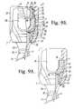
- FIG. 9Ais an enlarged and partial front elevational view of the bone screw assembly of FIG. 1 shown in a stage of assembly, with crimped projections of the receiver holding the insert in frictional engagement with the shank, the shank and retainer being in non-floppy frictional, but movable engagement with the receiver, with portions broken away to show the detail thereof.
- FIG. 9Bis an enlarged and partial front elevational view of the bone screw assembly of FIG. 1 shown in an assembled, locked position (but without a longitudinal connecting member), with portions broken away to show the detail thereof.
- FIG. 10is an enlarged and partial side elevational view, showing three bone screws of FIG. 1 and a longitudinal connecting member in the form of a rod.
- FIG. 11is an enlarged and partial side elevational view of one of the bone screws of FIG. 10 and the rod, with portions broken away to show the detail thereof.
- FIG. 12is an enlarged and partial cross-sectional view taken along the line 12 - 12 of FIG. 11 .
- FIG. 13is an enlarged and exploded perspective view of an alternative embodiment of a polyaxial bone screw assembly according to the invention including a bone screw shank, a receiver, a retaining structure, a cylindrical lower pressure insert and shown with a bar and a closure structure.
- FIG. 14is an enlarged and partial front elevational view of the shank, receiver, retaining structure and pressure insert of FIG. 13 with portions broken away to show the detail thereof.
- FIG. 15is an enlarged and partial perspective view of the shank, receiver, retaining structure, pressure insert and bar of FIG. 13 with portions broken away to show the detail thereof.
- the reference number 1generally represents a polyaxial bone screw apparatus or assembly in accordance with the present invention operably utilized by implantation into a vertebra (not shown) and in conjunction with a longitudinal connecting member, such as an illustrated rod 3 so as to operably secure the rod 3 in a fixed position relative with respect to the vertebra (not shown).
- the fully assembled bone anchor assembly 1includes a shank 6 , a receiver 7 , a retainer structure or ring 8 , a lower pressure insert 9 and a closure structure or top 10 .
- the shank 6is elongate and has an upper body portion 14 integral with a lower body portion 15 , ending in a tip 16 .
- the shank body 15has a helically wound bone implantable thread 17 extending from near the tip 16 to near the top 18 of the lower body 15 and extending radially outward therefrom. During use, the body 15 utilizing the thread 17 is implanted into a vertebra.
- the shank 6has an elongated axis of rotation generally identified by the reference letter A.
- Axially extending outward and upward from the shank body 15is a neck 20 , typically of reduced radius as compared to the adjacent top 18 of the body 15 .
- the shank upper portion 14operably providing a connective or capture structure free from the bone or vertebra for joining with the receiver 7 .
- the shank upper portion or capture structure 14has a radially outer cylindrical surface 22 .
- the cylindrical surface 22has at least one non-helically wound and radially outward or lateral extending projection or spline 24 that extends beyond the surface 22 .
- the shank upper portion 14has three such laterally extending splines 24 .
- bone anchors of the inventionhave at least one and up to a plurality of splines 24 .
- the bone anchorincludes from one to four splines.
- the splines 24are located near and extend outwardly from an upper edge 25 of the shank upper portion cylindrical surface 22 and are equally circumferentially centered and spaced thereabout so as to be centered at approximately 120 degree intervals relative to each other.
- Each of the splines 24has a substantially triangular shaped profile and a front wedge forming face 27 that slopes downwardly and radially inwardly from near the upper edge 25 .
- Adjacent the upper edge 25is a centrally located, axially extending and upwardly directed convex annular projection or dome-shaped upper end 29 that is centrally radiused.
- Each of the splines 24includes an upper surface 30 that is adjacent to and extends from the upper end surface 29 , having the same radius as the upper end surface 29 .
- Also formed in the shank upper portion 14 within an annular rim 28 of the end surface 29is a tool engagement aperture 31 for engagement by a tool driving head (not shown) that is sized and shaped to fit into the aperture for both driving and rotating the shank 6 into a vertebra.
- the aperture 31is star-shaped and runs parallel to the axis A.
- the illustrated shank 6is cannulated, having a through bore 32 extending an entire length of the shank 6 along the axis A.
- the bore 32is defined by an inner cylindrical wall of the shank 6 and has a circular opening at the shank tip 6 and an upper opening communicating with the internal drive feature 31 .
- the bore 32provides a passage through the shank 6 interior for a length of wire (not shown) inserted into the vertebra (not shown) prior to the insertion of the shank body 15 , the wire providing a guide for insertion of the shank body 15 into the vertebra (not shown).
- the threaded shank body 15may be coated, perforated, made porous or otherwise treated.
- the treatmentmay include, but is not limited to a plasma spray coating or other type of coating of a metal or, for example, a calcium phosphate; or a roughening, perforation or indentation in the shank surface, such as by sputtering, sand blasting or acid etching, that allows for bony ingrowth or ongrowth.
- Certain metal coatingsact as a scaffold for bone ingrowth.
- Bio-ceramic calcium phosphate coatingsinclude, but are not limited to: alpha-tri-calcium phosphate and beta-tri-calcium phosphate (Ca 3 (PO 4 ) 2 , tetra-calcium phosphate (Ca 4 P 2 O 9 ), amorphous calcium phosphate and hydroxyapatite (Ca n (PO 4 ) 6 (OH) 2 ).
- Coating with hydroxyapatitefor example, is desirable as hydroxyapatite is chemically similar to bone with respect to mineral content and has been identified as being bioactive and thus not only supportive of bone ingrowth, but actively taking part in bone bonding.
- the receiver 7has a generally squared-off U-shaped appearance with a partially cylindrical inner profile and a substantially faceted outer profile; however, the outer profile could also be of another configuration, for example, curved or cylindrical.
- a receiver axis of rotation Bis aligned with the axis of rotation A of the shank 6 during assembly of the receiver 7 with the shank 6 and the retainer 8 .
- the axis Bis typically disposed at an angle with respect to the axis A of the shank 6 .
- the receiver 7has a base 33 with a pair of upstanding arms 34 and 35 forming a U-shaped channel 38 between the arms 34 and 35 with a lower seat 39 having a slightly larger radius than the rod 3 for operably receiving the rod 3 .
- the insert 9 that is disposed within the receiver 7snugly receives the rod 3 as will be described more fully below.
- Each of the arms 34 and 35has an interior surface 41 that includes a partial helically wound guide and advancement structure 42 .
- the guide and advancement structure 42is a partial helically wound flangeform that mates under rotation with a similar structure on the closure top 10 , as described below.
- the guide and advancement structure 42could alternatively be a buttress thread, a reverse angle thread or other thread like or non-thread like helically wound advancement structures for operably guiding under rotation and advancing the closure top between the arms 34 and 35 .
- Tool engaging apertures 44are formed on the outsides of the arms 34 and 35 for holding the receiver 7 during certain assembly steps and/or implantation of the assembly and also for access to a thin deformable wall 45 during assembly with the pressure insert 9 .
- a chamber or cavity 47is located within the receiver base 33 that opens upwardly into the U-shaped channel 38 .
- the cavity 47includes a partial spherical shaped surface 48 , at least a portion of which forms a partial internal hemispherical seat for the retainer 8 , as is described further below.
- the hemispherical shaped surface 48has a second radius associated therewith.
- a lower neck 50 defining a lower borefurther communicates between the cavity 47 and the bottom exterior of the base 33 and is coaxial with the rotational axis B of the receiver 7 .
- the neck 50at least partially defines a restriction having a radius which is smaller than the radius of the retainer 8 , so as to form a restrictive constriction at the location of the neck 50 relative to the retainer 8 to prevent the retainer 8 from passing between the cavity 47 and the lower exterior of the receiver 7 .
- a substantially cylindrical surface 52that includes a run-out surface 53 located directly beneath the guide and advancement structure 42 .
- the retainer 8is substantially ring-shaped and has an operational central axis which is the same as the elongate axis A associated with the shank 6 , but when the retainer 8 is separated from the shank 6 , the axis of rotation is identified as axis C.
- the retainer 8has a central bore 57 that passes entirely through the retainer 8 from a top surface 58 to a bottom surface 59 thereof.
- the bore 57is sized and shaped to fit snugly but slidably over the shank capture structure cylindrical surface 22 in such a manner as to allow sliding axial movement therebetween under certain conditions, as described below.
- Three axially aligned channels 60are spaced from the axis C and extend radially outward from the bore 57 and into the wall of the retainer 8 so as to form three top to bottom grooves or slots therein.
- Backs 61 of the channels 60are the same radial distance from the axis C as the distance the outermost portion of the splines 24 extend from the axis A of the shank 6 .
- the channels 60are also circumferentially angularly spaced equivalent to and have a width that corresponds with the splines 24 .
- the shank upper portion 14can be uploaded into the retainer 8 by axially sliding the shank upper portion 14 through the retainer 8 central bore 57 whenever the splines 24 are aligned with the channels 60 or are in an aligned configuration.
- the details of assembly and subsequent cooperation between the shank 6 , the retainer 8 and the receiver 7are described in detail in Applicant's U.S. Pat. No. 6,716,214 issued Apr. 6, 2004, the entire disclosure of which is incorporated by reference herein.
- the retainer 8also has three capture partial slots, holding pockets, receivers or recesses 62 which extend radially outward from the upper part of the bore 57 and that do not extend the entire length from top to bottom of the retainer 8 , but rather only open on the top surface 58 and extend partly along the height of the retainer 8 thereof.
- the holding pockets or recesses 62are sized and positioned and shaped to receive the splines 24 from above when the splines 24 are in a non-aligned configuration relative to the channels 60 .
- each of the recesses or pockets 62has a width that approximates the width of the splines 24 and has a mating wedge engaging surface 64 that is shaped similar to the spline wedge forming faces 27 , so that the splines 24 can be slidably received into the recesses 62 from above by axially translating or moving the shank 6 downward relative to the retainer ring 8 when the splines 24 are positioned above the recesses 62 in a recess aligned configuration.
- the wedge engaging faces 64slope slightly greater than the wedge forming faces 27 on the splines 24 so that there is additional outward wedging that takes place when the splines 24 are urged downwardly into the recesses 62 .
- the shank upper portion 14can be uploaded or pushed upwardly through the retainer central bore 57 so as to clear the top 58 of the retainer ring 8 , rotated approximately 60 degrees and then downloaded or brought downwardly so that the splines 24 become located and captured in the recesses 62 .
- the retainer 8is constructed of a metal or other material having sufficient resilience and elasticity as to allow the retainer 8 to radially expand slightly outward by downward pressure of the splines 24 on the recesses 62 under pressure from structure above, as will be discussed further below. This produces a slight outward radial expansion in the retainer ring 8 at the location of the recesses 62 .
- the retainer 8has a radially outer partial hemispherical shaped surface 65 sized and shaped to mate with the partial spherical shaped surface 48 and having a third radius approximately equal to the second radius associated with the surface 48 .
- the retainer 8 third radiusis substantially larger than the radius associated with the annular curved surface 29 of the shank upper portion 14 and also substantially larger than the radius of the receiver neck 50 .
- the lower compression or pressure insert 9includes a substantially cylindrical body 70 integral with a pair of upstanding arms 72 .
- the body 70 and arms 72form a generally U-shaped, open, through-channel 74 having a lower seat 76 sized and shaped to closely, snugly engage the rod 3 .
- the insert 9may be configured to include planar holding surfaces that closely hold a square or rectangular bar as well as hold a cylindrical rod-shaped or corded longitudinal connecting member.
- the arms 72 disposed on either side of the channel 74extend outwardly from the body 70 .
- the arms 72are sized and configured for placement near the run-out 53 below the guide and advancement structure 42 at the receiver inner arms 34 and 35 .
- each of the arms 72includes a top surface 78 ultimately located directly beneath the guide and advancement structure 42 and are directly engaged by the closure top 10 for locking the polyaxial mechanism of the assembly 1 , even without a longitudinal connecting member as shown in FIG. 9B . Therefore, the assembly 1 may be used with a wide variety of longitudinal connecting members, including rods that engage the closure top 10 and are locked into position by such closure top 10 as well as rods of smaller diameter or cords that are captured by the closure top 10 , but are otherwise movable within the receiver 7 and are thus in slidable or spaced relation with the closure top 10 . In this manner, the locked polyaxial open screw can function like a closed, fixed monoaxial screw.
- Each arm 72further includes a partially cylindrical outer surface 80 sized and shaped to fit within the receiver 7 at the guide and advancement structure 42 run-out relief 53 .
- the cylindrical surfaces 80are disposed substantially perpendicular to the respective adjacent top surfaces 78 .
- recessesare formed near and/or at the top surfaces 78 and the surfaces that form the channel 74 to provide relief for material flow of the longitudinal connecting member, when, for example, the connector is made from a deformable plastic or elastic or inelastic polymer.
- a recessed surface or groovemay be directed downwardly and inwardly toward the channel 74 .
- Each of the outer surfaces 80further includes a recess 82 sized and shaped to receive holding tabs or crimped material from the receiver 7 .
- the thin walls 45 of the receiver 7are pressed into the recesses 82 to prevent rotation of the insert 9 about the axis B with respect to the receiver 7 .
- the receiver 7may be equipped with spring tabs that snap into the recesses 82 to hold the insert 9 in place with respect to rotation.
- the recesses 82are oval or elongate such that some desirable upward and downward movement of the insert 9 along the axis B of the receiver 7 is not prohibited.
- the compression insert 9further includes an inner cylindrical surface 84 that forms a through bore sized and shaped to receive a driving tool (not shown) therethrough that engages the shank drive feature 31 when the shank body 15 is driven into bone.
- the inner surface 84runs between the seating surface 76 and an inner curved, annular, radiused or semi-spherical surface 86 .
- the surface 86is sized and shaped to slidingly and pivotally mate with and ultimately fix against the annular domed surface 29 of the shank upper portion 14 .
- a radius of the surface 86is the same or substantially similar to the radius of the surface 29 .
- the surface 86may include a roughening or surface finish to aid in frictional contact between the surface 86 and the surface 29 , once a desired angle of articulation of the shank 6 with respect to the receiver 7 is reached.
- Adjacent to the inner surface 86is a bottom rim or edge 88 .
- Adjacent to the outer cylindrical surface 80 of the arms 72is a substantially conical surface 90 that extends inwardly toward the lower rim 88 .
- the surface 90includes portions of the arms 72 as well as partially defining the pressure insert body 70 . In some embodiments of the invention, the surface 90 terminates at the rim 88 .
- the insert 9is further trimmed near the base rim 88 to ensure clearance between the insert 9 and the retainer 8 .
- a v-shaped cutis formed in the insert 9 near the rim 88 , the cut being defined by sloping surfaces 92 and 93 .
- the surface 92is adjacent the base rim 88 and the surface 93 is located between the surface 92 and the surface 90 .
- the pressure insert body 70 located between the arms 72has an outer diameter slightly smaller than a diameter between crests of the guide and advancement structure 42 of the receiver 7 allowing for top loading of the compression insert 9 into the receiver 7 through the U-shaped channel 38 , with the arms 72 being located between the arms 34 and 35 during insertion of the insert 9 into the receiver 7 .
- the insert 9is rotated into place about the axis B until the arms 72 are directly below the guide and advancement structure 42 at or near the run-out 53 .
- a tool(not shown) may be inserted into the receiver apertures 44 to press the thin receiver walls 45 into the insert recesses 82 .
- the lower compression insert 9is sized such that the insert 9 is ultimately received within the cylindrical surface 52 of the receiver 7 below the guide and advancement structure 42 .
- the receiver 7fully receives the lower compression insert 9 and blocks the structure 9 from spreading or splaying in any direction. It is noted that assembly of the shank 6 with the retainer 8 within the receiver 7 , followed by insertion of the lower compression insert 9 into the receiver 7 are assembly steps typically performed at the factory, advantageously providing a surgeon with a polyaxial bone screw with the lower insert 9 already held in alignment with the receiver 7 and thus ready for insertion into a vertebra.
- the compression or pressure insert 9ultimately seats on the shank upper portion 14 and is disposed substantially in the upper cylindrical portion 52 of the cavity 47 , with the receiver deformable walls 45 engaging the insert 9 at the recesses 82 , thereby holding the insert 7 in desired alignment with respect to the longitudinal connecting member 3 .
- the assemblymay be configured so that the insert 9 extends at least partially into the U-shaped channel 38 such that the seating surface 76 substantially contacts and engages an adjacent surface of the rod 3 when the rod 3 is placed in the receiver 7 and the closure structure or top 10 is tightened against the rod, the illustrated rod 3 being fixedly held in spaced relation with the lower seat 39 of the receiver 7 .
- a cord or smaller diameter rodmay be held in sliding engagement with the insert 9 , the shank 6 being locked into a desired position by engagement of the closure top 10 with the insert 9 and engagement of the insert 9 with the shank upper portion 14 , which in turn presses the retainer 8 against the receiver seating surface 48 .
- the elongate connecting member illustrated in the drawing figuresis a hard, inelastic solid cylindrical rod 3 of circular cross-section the diameter of which can vary depending on the application.
- longitudinal connecting members for use with the assembly 1may take a variety of shapes, including but not limited to rods or bars of oval, rectangular or other curved or polygonal cross-section.
- the size and shape of the insert 9 channelmay be modified so as to loosely hold or more closely hold, and if desired, fix the longitudinal connecting member to the assembly 1 .
- the assembly 1may also be used with an elastic tensioned cord.
- Such a cordmay be made from a variety of materials, including polyester or other plastic fibers, strands or threads, such as polyethylene-terephthalate.
- the polyaxial screwcan be securely locked when using any of the longitudinal connecting members.
- the longitudinal connector 3may be a component of a longer overall dynamic stabilization connecting member, with cylindrical or bar-shaped portions sized and shaped for being received by the compression insert 9 of the receiver 7 having a u-shaped channel (or rectangular- or other-shaped channel) for loosely or more closely receiving the longitudinal connecting member.
- the longitudinal connecting member 3may be integral or otherwise fixed to a bendable or damping component that is sized and shaped to be located between adjacent pairs of bone screw assemblies 1 , for example.
- a damping component or bumpermay surround and/or be attached to the member 3 at one or both sides of the bone screw assembly 1 and the bumper may engage the screw head.
- a rod or bar (or rod or bar component) of a longitudinal connecting membermay be made of a variety of materials ranging from deformable plastics to hard metals, depending upon the desired application.
- bars and rods of the inventionmay be made of materials including, but not limited to metal and metal alloys including but not limited to stainless steel, titanium, titanium alloys and cobalt chrome; or other suitable materials, including plastic polymers such as polyetheretherketone (PEEK), ultra-high-molecular weight-polyethylene (UHMWP), polyurethanes and composites, including composites containing carbon fiber, natural or synthetic elastomers such as polyisoprene (natural rubber), and synthetic polymers, copolymers, and thermoplastic elastomers, for example, polyurethane elastomers such as polycarbonate-urethane elastomers.
- plastic polymerssuch as polyetheretherketone (PEEK), ultra-high-molecular weight-polyethylene (UHMWP), polyurethanes and composites, including composites containing carbon fiber, natural or synthetic elastomers such as polyisoprene (natural rubber), and synthetic polymers, copolymers, and thermoplastic elastomers
- the closure structure or closure top 10can be any of a variety of different types of closure structures for use in conjunction with the present invention with suitable mating structure on the upstanding arms 34 and 35 .
- the closure top 10is rotatably received between the spaced arms 34 and 35 of the receiver 7 .
- the illustrated closure structure 10is substantially cylindrical and includes an outer helically wound guide and advancement structure 95 in the form of a flange form that operably joins with the guide and advancement structure 42 of the receiver 7 .
- the flange form utilized in accordance with the present inventionmay take a variety of forms, including those described in Applicant's U.S. Pat. No. 6,726,689, which is incorporated herein by reference.
- closure structure guide and advancement structurecould alternatively be a buttress thread, a square thread, a reverse angle thread or other thread like or non-thread like helically wound advancement structure for operably guiding under rotation and advancing the closure structure 10 downward between the arms 34 and 35 and having such a nature as to resist splaying of the arms 34 and 35 when the closure structure 10 is advanced into the channel 38 .
- the illustrated closure structure 10also includes a top surface 96 with an internal drive 97 in the form of an aperture that is illustrated as a star-shaped internal drive, but may be, for example, a hex-shaped drive or other internal drives, including, but not limited to slotted, tri-wing, spanner, two or more apertures of various shapes, and the like.
- a driving tool(not shown) sized and shaped for engagement with the internal drive 97 is used for both rotatable engagement and, if needed, disengagement of the closure 10 from the receiver arms 34 and 35 .
- the closure structure 10may alternatively include a break-off head designed to allow such a head to break from a base of the closure at a preselected torque, for example, 70 to 140 inch pounds.
- Such a closure structurewould also include a base having an internal drive to be used for closure removal.
- a bottom surface 98 of the closure top 10is planar, but could be domed or radiused and may include a point, points, a rim or roughening for engagement with the rod 3 .
- the closure topmay include an extended base, central cylinder, cap or knob for pressing into a deformable rod or compressing a cord or cable against the insert seating surface.
- Such an extension or knobwould be sized and shaped to extend into the channel 74 of the insert and also clear the walls defining the channel 74 so that a portion of the closure top still abuts against the insert 9 , locking the polyaxial mechanism of the bone screw.
- the illustrated bottom surface 98 of the closure top 10is sized and shaped for engagement with the top planar surfaces 78 of the arms 72 of the lower pressure or compression insert 9 .
- engagement of the surface 98 with the surfaces 78independently locks the polyaxial mechanism of the bone screw 1 , the insert 9 being pushed downwardly toward the shank upper portion 14 by the closure 10 that in turn presses the retainer 8 against the receiver 7 at the seating surface 48 .
- the surface 98 of the closure top 10also can barely touch or firmly frictionally engage the rod 3 , capturing and/or locking the rod in position between the closure top 10 and the insert 9 .
- a smaller rod, cable or cordmay remain in sliding engagement with the closure top 10 with the top 10 being only in frictional engagement with the insert 9 to lock the polyaxial mechanism of the assembly 1 and fix the angular configuration of the shank 6 with respect to the receiver 7 without fixing the rod, cable or cord captured by the receiver 7 and between the insert and the closure top 10 .
- the rod 3may undergo creep or other plastic deformation that may lessen the engagement between the cylindrical surface of the rod 3 and the closure surface 98 .
- the frictional engagement between the closure member 10 and the lower compression insert 9both preferably made from a metal or metal alloy, such as cobalt chrome, stainless steel or titanium, will remain rigid and secure.
- the closure top 10may further include a cannulation through bore extending along a central axis thereof and through a surface of the drive 97 and the bottom surface 98 .
- a through boreprovides a passage through the closure 10 interior for a length of wire (not shown) inserted therein to provide a guide for insertion of the closure top into the receiver arms 34 and 35 , after which the wire could be removed and the rod, cable or cord could then be threaded or inserted through the receiver.
- the retainer 8When the polyaxial bone screw assembly 1 is placed in use in accordance with the invention the retainer 8 is normally first slid through the receiver U-shaped channel 38 and into and seated in the receiver cavity 47 . Thereafter, the retainer 8 is rotated 90 degrees so as to be coaxial with the receiver 7 and so that the retainer outer surface 65 snugly but slidably mates with the receiver interior spherical shaped surface 48 . The retainer 8 in the receiver 7 is then slid over the shank upper portion 14 so that the splines 24 slide upwardly through and above respective channels 60 so that the splines 24 are then located, at least partially, in the U-shaped channel 38 and chamber 47 above the retainer ring 8 .
- the shank 6is then rotated 60 degrees relative to the receiver about the axis A and the translational direction of the shank 6 is reversed so that it goes downwardly or axially with respect to the receiver 7 , and the splines 24 enter the recesses 62 .
- the retainer 8is easily rotatable along with the shank 6 within the chamber 47 and such rotation is of a ball and socket type wherein the angle of rotation is only restricted by engagement of the neck 20 with the neck 50 of the receiver 7 .
- the insert 9is inserted into the channel 38 with the arms 72 aligned in the channel 38 between the guide and advancement structures 42 .
- the insert 9is then moved downwardly in the channel 38 and toward the cavity 47 .
- the insert 9is rotated about the axis B of the receiver 7 .
- the arms 72fit within the cylindrical walls 52 above the cavity 47 .
- rotationis ceased and a tool (not shown) is used to press the thin walls 45 of the receiver 7 into the recesses 82 of the insert 9 .
- the insert 9is now locked into place inside the receiver 7 with the guide and advancement structures 42 prohibiting upward movement of the insert 9 out of the channel 38 and the crimped walls 45 preventing rotation of the insert 9 .
- the insert 9seats on the shank upper portion 14 with the surface 86 in sliding engagement with the surface 29 .
- the run-out or relief 53is sized and shaped to allow for some upward and downward movement of the insert 9 toward and away from the shank upper portion 14 such that the shank 6 is pivotable with respect to the receiver 7 until the closure structure 10 presses on the insert 9 that in turn presses upon the upper portion 14 into locking frictional engagement with the receiver 7 at the surface 48 .
- This assembly processis generally performed by the manufacturer.
- the walls 45may be crimped at a location with respect to the insert aperture 44 that causes the surface 86 of the insert 9 to bias against and frictionally engage the shank domed surface 29 to provide a sub-assembly in which the shank 6 is pivotable with respect to the receiver 7 , but in a non-floppy manner, making it easier for a surgeon to position the receiver 7 at a desired articulation with respect to the shank 6 and have the assembly hold such desired position prior to insertion of the rod 3 or other longitudinal connecting member.
- the sub-assembly as shown in FIG. 9Ais then normally screwed into a bone, such as vertebra, by rotation of the shank 6 using a suitable driving tool (not shown) that operably drives and rotates the shank 6 by engagement thereof at the internal drive 31 .
- a suitable driving tool(not shown) that operably drives and rotates the shank 6 by engagement thereof at the internal drive 31 .
- the receiver 7 , retainer 8 and insert 9are assembled on the shank 6 before placing the shank 6 in the vertebra, but in certain circumstances, the shank 6 can be first implanted with the capture structure 14 extending proud to allow assembly and then the shank 6 can be further driven into the vertebra.
- a rod 3is eventually positioned within the receiver U-shaped channel 38 , as is seen in FIGS. 10-12 , and the closure top 10 is then inserted into and advanced between the arms 34 and 35 so as to bias or push against the insert 9 (and here, the rod 3 also).
- a driving tool(not shown) is inserted into the drive 97 to rotate and drive the closure top 10 into the receiver 7 .
- the shank dome 29is engaged by the insert 9 and pushed downwardly when the closure top 10 pushes downwardly on the insert 9 , as is seen in FIG. 12 .
- the downward pressure on the shank 6in turn urges the splines 24 downwardly which exerts both a downward and outward thrust on the retainer ring 8 .
- FIG. 10Three polyaxial bone screws 1 , including the rod 3 , are shown in FIG. 10 , illustrating various shank 6 to receiver 7 angular configurations. Furthermore, FIGS. 11 and 12 illustrate a particular angular configuration in which the axis A of the bone screw shank 6 is not coaxial with the axis B of the receiver 7 and the shank 6 is locked in this angular locked configuration.
- the assembly 1can be disassembled by using a driving tool mating with the closure top aperture 97 to rotate the closure top 10 and reverse the advancement thereof in the receiver 7 . Then, disassembly of the remainder of the assembly 1 may be accomplished in reverse mode in comparison to the procedure described above for assembly.
- FIGS. 13-15Illustrated in FIGS. 13-15 is a second embodiment of a bone screw assembly, generally 201 , according to the present invention.
- the assemblyincludes a shank 206 , a receiver 207 , a retainer 208 , a cylindrical lower pressure insert 209 and a closure top 210 having a break-off head.
- the assemblyis shown with a longitudinal connecting member in the form of a bar 203 .
- the shank 206includes an upper portion 214 that is substantially similar in form and function to the portion 14 of the shank 6 of the assembly 1 and the retainer ring 208 is substantially similar in form and function to the retainer ring 8 of the assembly 1 .
- the receiver 207is somewhat similar to the receiver 7 of the assembly 1 and differences between the receiver 7 and the receiver 207 include the feature of spring tabs 221 for holding the insert 209 within the receiver 207 and planar seating surfaces 239 , 240 and 241 for receiving the bar 203 .
- the pressure insert 209includes a substantially cylindrical body with an outer cylindrical surface 280 .
- the insertalso includes a lower spherical surface 286 sized and shaped for slidably mating with an upper domed surface 229 of the shank upper portion 214 .
- the insert 209includes a planar top surface 278 upon which the bar 203 is received.
- the closure top 210presses upon the bar 203 that in turn presses upon the insert 209 that presses'directly upon the shank upper portion 229 and not upon the retainer 208 .
- Downward movement of the shank upper portion 229 that is fixed to the retainer 208then in turn presses an outer spherical surface 265 of the retainer 208 against an inner seating surface 248 of the receiver 207 .
- the insert 209remains spaced from the retainer 208 and does not make contact with the retainer 208 in any angular configuration of the shank 206 with respect to the receiver 207 .
Landscapes
- Health & Medical Sciences (AREA)
- Orthopedic Medicine & Surgery (AREA)
- Life Sciences & Earth Sciences (AREA)
- Surgery (AREA)
- Neurology (AREA)
- Heart & Thoracic Surgery (AREA)
- Engineering & Computer Science (AREA)
- Biomedical Technology (AREA)
- Nuclear Medicine, Radiotherapy & Molecular Imaging (AREA)
- Medical Informatics (AREA)
- Molecular Biology (AREA)
- Animal Behavior & Ethology (AREA)
- General Health & Medical Sciences (AREA)
- Public Health (AREA)
- Veterinary Medicine (AREA)
- Surgical Instruments (AREA)
Abstract
Description
Claims (16)
Priority Applications (2)
| Application Number | Priority Date | Filing Date | Title |
|---|---|---|---|
| US12/661,986US8377102B2 (en) | 2003-06-18 | 2010-03-26 | Polyaxial bone anchor with spline capture connection and lower pressure insert |
| US13/694,981US20130138160A1 (en) | 2003-06-18 | 2013-01-23 | Polyaxial Bone Anchor With Spline Capture Connection And Lower Pressure Insert |
Applications Claiming Priority (14)
| Application Number | Priority Date | Filing Date | Title |
|---|---|---|---|
| US10/464,633US6716214B1 (en) | 2003-06-18 | 2003-06-18 | Polyaxial bone screw with spline capture connection |
| US10/651,003US8137386B2 (en) | 2003-08-28 | 2003-08-28 | Polyaxial bone screw apparatus |
| US10/818,555US8052724B2 (en) | 2003-06-18 | 2004-04-05 | Upload shank swivel head bone screw spinal implant |
| US10/818,554US7662175B2 (en) | 2003-06-18 | 2004-04-05 | Upload shank swivel head bone screw spinal implant |
| US11/024,543US7204838B2 (en) | 2004-12-20 | 2004-12-20 | Medical implant fastener with nested set screw and method |
| US11/140,343US7776067B2 (en) | 2005-05-27 | 2005-05-27 | Polyaxial bone screw with shank articulation pressure insert and method |
| US11/522,503US7766915B2 (en) | 2004-02-27 | 2006-09-14 | Dynamic fixation assemblies with inner core and outer coil-like member |
| US93136207P | 2007-05-23 | 2007-05-23 | |
| US96407P | 2007-10-30 | 2007-10-30 | |
| US12/154,460US8257396B2 (en) | 2003-06-18 | 2008-05-23 | Polyaxial bone screw with shank-retainer inset capture |
| US12/290,244US7967850B2 (en) | 2003-06-18 | 2008-10-29 | Polyaxial bone anchor with helical capture connection, insert and dual locking assembly |
| US21116909P | 2009-03-27 | 2009-03-27 | |
| US12/587,244US20100030280A1 (en) | 2003-06-18 | 2009-10-02 | Upload shank swivel head bone screw spinal implant |
| US12/661,986US8377102B2 (en) | 2003-06-18 | 2010-03-26 | Polyaxial bone anchor with spline capture connection and lower pressure insert |
Related Parent Applications (4)
| Application Number | Title | Priority Date | Filing Date |
|---|---|---|---|
| US11/522,503Continuation-In-PartUS7766915B2 (en) | 2003-06-18 | 2006-09-14 | Dynamic fixation assemblies with inner core and outer coil-like member |
| US12/154,460Continuation-In-PartUS8257396B2 (en) | 2003-06-18 | 2008-05-23 | Polyaxial bone screw with shank-retainer inset capture |
| US12/290,244Continuation-In-PartUS7967850B2 (en) | 2003-06-18 | 2008-10-29 | Polyaxial bone anchor with helical capture connection, insert and dual locking assembly |
| US12/587,244Continuation-In-PartUS20100030280A1 (en) | 2003-06-18 | 2009-10-02 | Upload shank swivel head bone screw spinal implant |
Related Child Applications (3)
| Application Number | Title | Priority Date | Filing Date |
|---|---|---|---|
| US10/464,633Continuation-In-PartUS6716214B1 (en) | 2003-04-09 | 2003-06-18 | Polyaxial bone screw with spline capture connection |
| US10/651,003ContinuationUS8137386B2 (en) | 2003-06-18 | 2003-08-28 | Polyaxial bone screw apparatus |
| US13/694,981ContinuationUS20130138160A1 (en) | 2003-06-18 | 2013-01-23 | Polyaxial Bone Anchor With Spline Capture Connection And Lower Pressure Insert |
Publications (2)
| Publication Number | Publication Date |
|---|---|
| US20100191293A1 US20100191293A1 (en) | 2010-07-29 |
| US8377102B2true US8377102B2 (en) | 2013-02-19 |
Family
ID=42354790
Family Applications (2)
| Application Number | Title | Priority Date | Filing Date |
|---|---|---|---|
| US12/661,986Expired - Fee RelatedUS8377102B2 (en) | 2003-06-18 | 2010-03-26 | Polyaxial bone anchor with spline capture connection and lower pressure insert |
| US13/694,981AbandonedUS20130138160A1 (en) | 2003-06-18 | 2013-01-23 | Polyaxial Bone Anchor With Spline Capture Connection And Lower Pressure Insert |
Family Applications After (1)
| Application Number | Title | Priority Date | Filing Date |
|---|---|---|---|
| US13/694,981AbandonedUS20130138160A1 (en) | 2003-06-18 | 2013-01-23 | Polyaxial Bone Anchor With Spline Capture Connection And Lower Pressure Insert |
Country Status (1)
| Country | Link |
|---|---|
| US (2) | US8377102B2 (en) |
Cited By (17)
| Publication number | Priority date | Publication date | Assignee | Title |
|---|---|---|---|---|
| US20120197312A1 (en)* | 2011-01-28 | 2012-08-02 | Warsaw Orthopedic, Inc. | Thread introduction features for an orthopedic implant |
| US20120303070A1 (en)* | 2005-09-30 | 2012-11-29 | Jackson Roger P | Polyaxial bone anchor assembly with one-piece closure, pressure insert and plastic elongate member |
| US20140114365A1 (en)* | 2005-05-10 | 2014-04-24 | Acumed Llc | Bone connector with pivotable joint |
| US20140172023A1 (en)* | 2006-04-12 | 2014-06-19 | Alphatec Spine, Inc. | Pedicle screw assembly |
| US9451992B2 (en)* | 2010-12-01 | 2016-09-27 | Facet-Link Inc. | Variable angle bone screw fixation arrangement |
| US20190307489A1 (en)* | 2010-11-02 | 2019-10-10 | Roger P. Jackson | Pivotal bone anchor assembly with pressure insert and snap on articulating retainer |
| US10610265B1 (en) | 2017-07-31 | 2020-04-07 | K2M, Inc. | Polyaxial bone screw with increased angulation |
| US10765455B2 (en) | 2009-06-15 | 2020-09-08 | Roger P. Jackson | Pivotal bone anchor twist-in-place friction fit insert with side notches |
| US10813671B2 (en) | 2009-06-15 | 2020-10-27 | Roger P. Jackson | Method of assembling a bone anchor receiver assembly having an insert with rotation blocking extensions and a downward facing collet |
| US10856909B2 (en) | 2008-08-01 | 2020-12-08 | Roger P. Jackson | Bone anchor insert with rotation blocking extensions and tool forced displacement |
| US10869694B2 (en) | 2009-06-15 | 2020-12-22 | Roger P. Jackson | Pivotal bone anchor assembly with independent locking by a tool engaging an insert |
| US10918420B2 (en) | 2009-06-15 | 2021-02-16 | Roger P. Jackson | Pivotal bone anchor assembly with forced downward displacement of a compression insert by a tool |
| US11109896B2 (en) | 2009-06-15 | 2021-09-07 | Roger P. Jackson | Uniplanar bone anchor assembly |
| US11234745B2 (en) | 2005-07-14 | 2022-02-01 | Roger P. Jackson | Polyaxial bone screw assembly with partially spherical screw head and twist in place pressure insert |
| US11464549B2 (en) | 2009-06-15 | 2022-10-11 | Roger P. Jackson | Pivotal bone anchor assembly with horizontal tool engagement grooves and insert with upright arms having flared outer portions |
| US11975825B2 (en) | 2020-11-23 | 2024-05-07 | Textron Innovations Inc. | Spline with expendable spherical alignment head |
| US12121268B2 (en) | 2021-07-07 | 2024-10-22 | Globus Medical, Inc. | Modular orthopedic implants, instruments, and navigation methods |
Families Citing this family (38)
| Publication number | Priority date | Publication date | Assignee | Title |
|---|---|---|---|---|
| US7833250B2 (en) | 2004-11-10 | 2010-11-16 | Jackson Roger P | Polyaxial bone screw with helically wound capture connection |
| US8876868B2 (en) | 2002-09-06 | 2014-11-04 | Roger P. Jackson | Helical guide and advancement flange with radially loaded lip |
| US7377923B2 (en) | 2003-05-22 | 2008-05-27 | Alphatec Spine, Inc. | Variable angle spinal screw assembly |
| US8926670B2 (en) | 2003-06-18 | 2015-01-06 | Roger P. Jackson | Polyaxial bone screw assembly |
| US7766915B2 (en) | 2004-02-27 | 2010-08-03 | Jackson Roger P | Dynamic fixation assemblies with inner core and outer coil-like member |
| US7776067B2 (en) | 2005-05-27 | 2010-08-17 | Jackson Roger P | Polyaxial bone screw with shank articulation pressure insert and method |
| US7503924B2 (en) | 2004-04-08 | 2009-03-17 | Globus Medical, Inc. | Polyaxial screw |
| US8475495B2 (en) | 2004-04-08 | 2013-07-02 | Globus Medical | Polyaxial screw |
| US8926672B2 (en) | 2004-11-10 | 2015-01-06 | Roger P. Jackson | Splay control closure for open bone anchor |
| US9168069B2 (en) | 2009-06-15 | 2015-10-27 | Roger P. Jackson | Polyaxial bone anchor with pop-on shank and winged insert with lower skirt for engaging a friction fit retainer |
| US7901437B2 (en) | 2007-01-26 | 2011-03-08 | Jackson Roger P | Dynamic stabilization member with molded connection |
| EP1708358A3 (en)* | 2005-03-11 | 2006-12-06 | LG Electronics Inc. | Mobile communications terminal having driving voltage control apparatus and method thereof |
| EP2484300B1 (en)* | 2008-09-05 | 2015-05-20 | Biedermann Technologies GmbH & Co. KG | Stabilization device for bones, in particular for the spinal column |
| US9668771B2 (en) | 2009-06-15 | 2017-06-06 | Roger P Jackson | Soft stabilization assemblies with off-set connector |
| US8998959B2 (en) | 2009-06-15 | 2015-04-07 | Roger P Jackson | Polyaxial bone anchors with pop-on shank, fully constrained friction fit retainer and lock and release insert |
| US11229457B2 (en) | 2009-06-15 | 2022-01-25 | Roger P. Jackson | Pivotal bone anchor assembly with insert tool deployment |
| US9113960B2 (en)* | 2010-06-08 | 2015-08-25 | Globus Medical, Inc. | Conforming bone stabilization receiver |
| EP2457527B1 (en) | 2010-11-24 | 2014-04-16 | Biedermann Technologies GmbH & Co. KG | Polyaxial bone anchoring device with enlarged pivot angle |
| JP5865479B2 (en)* | 2011-03-24 | 2016-02-17 | ロジャー・ピー・ジャクソン | Multiaxial bone anchor with compound joint and pop-mounted shank |
| US9198694B2 (en) | 2011-07-15 | 2015-12-01 | Globus Medical, Inc. | Orthopedic fixation devices and methods of installation thereof |
| US9993269B2 (en) | 2011-07-15 | 2018-06-12 | Globus Medical, Inc. | Orthopedic fixation devices and methods of installation thereof |
| US8888827B2 (en) | 2011-07-15 | 2014-11-18 | Globus Medical, Inc. | Orthopedic fixation devices and methods of installation thereof |
| US9358047B2 (en) | 2011-07-15 | 2016-06-07 | Globus Medical, Inc. | Orthopedic fixation devices and methods of installation thereof |
| US9186187B2 (en) | 2011-07-15 | 2015-11-17 | Globus Medical, Inc. | Orthopedic fixation devices and methods of installation thereof |
| ES2504067T3 (en)* | 2011-08-18 | 2014-10-08 | Biedermann Technologies Gmbh & Co. Kg | Polyaxial bone anchoring device with extended turning angle |
| EP2559391B1 (en) | 2011-08-18 | 2014-06-18 | Biedermann Technologies GmbH & Co. KG | Polyaxial bone anchoring system |
| US8956361B2 (en) | 2011-12-19 | 2015-02-17 | Amendia, Inc. | Extended tab bone screw system |
| US8911479B2 (en) | 2012-01-10 | 2014-12-16 | Roger P. Jackson | Multi-start closures for open implants |
| EP2837347B1 (en) | 2012-01-30 | 2018-10-03 | Biedermann Technologies GmbH & Co. KG | Bone anchoring device |
| US8911478B2 (en) | 2012-11-21 | 2014-12-16 | Roger P. Jackson | Splay control closure for open bone anchor |
| US10058354B2 (en) | 2013-01-28 | 2018-08-28 | Roger P. Jackson | Pivotal bone anchor assembly with frictional shank head seating surfaces |
| US8852239B2 (en) | 2013-02-15 | 2014-10-07 | Roger P Jackson | Sagittal angle screw with integral shank and receiver |
| EP2967671B1 (en) | 2013-03-15 | 2021-11-17 | Biomet C.V. | Polyaxial pivot housing for external fixation system |
| US9566092B2 (en) | 2013-10-29 | 2017-02-14 | Roger P. Jackson | Cervical bone anchor with collet retainer and outer locking sleeve |
| US9717533B2 (en) | 2013-12-12 | 2017-08-01 | Roger P. Jackson | Bone anchor closure pivot-splay control flange form guide and advancement structure |
| US9451993B2 (en) | 2014-01-09 | 2016-09-27 | Roger P. Jackson | Bi-radial pop-on cervical bone anchor |
| US9597119B2 (en) | 2014-06-04 | 2017-03-21 | Roger P. Jackson | Polyaxial bone anchor with polymer sleeve |
| US10064658B2 (en) | 2014-06-04 | 2018-09-04 | Roger P. Jackson | Polyaxial bone anchor with insert guides |
Citations (514)
| Publication number | Priority date | Publication date | Assignee | Title |
|---|---|---|---|---|
| US2346346A (en) | 1941-01-21 | 1944-04-11 | Anderson Roger | Fracture immobilization splint |
| US2362999A (en) | 1943-06-28 | 1944-11-21 | Hewitt Elmer Spencer | Screwhead |
| US2531892A (en) | 1947-01-27 | 1950-11-28 | Richard T Reese | Bolt and nut fixture |
| US2813450A (en) | 1954-05-03 | 1957-11-19 | Dzus William | Rotatable fastener having circular toothed tool receiving groove |
| US3013244A (en) | 1957-05-01 | 1961-12-12 | Verdugo Products Company | Clamp connection and spacer for electrical transmission lines |
| US4033139A (en) | 1974-02-08 | 1977-07-05 | Frederick Leonard L | Pile driving hammer, apparatus and method |
| US4759672A (en) | 1987-05-08 | 1988-07-26 | Illinois Tool Works Inc. | Fastener head with stabilizing ring |
| US4790297A (en) | 1987-07-24 | 1988-12-13 | Biotechnology, Inc. | Spinal fixation method and system |
| US4946458A (en) | 1986-04-25 | 1990-08-07 | Harms Juergen | Pedicle screw |
| US5019080A (en) | 1990-02-13 | 1991-05-28 | Trextron Inc. | Drive system for prosthetic fasteners |
| US5129388A (en) | 1989-02-09 | 1992-07-14 | Vignaud Jean Louis | Device for supporting the spinal column |
| US5207678A (en) | 1989-07-20 | 1993-05-04 | Prufer | Pedicle screw and receiver member therefore |
| US5261912A (en) | 1990-08-21 | 1993-11-16 | Synthes (U.S.A.) | Implant for an osteosynthesis device, in particular for spinal column correction |
| US5312404A (en) | 1990-07-24 | 1994-05-17 | Acromed Corporation | Spinal column retaining apparatus |
| US5360431A (en) | 1990-04-26 | 1994-11-01 | Cross Medical Products | Transpedicular screw system and method of use |
| US5395371A (en) | 1991-07-15 | 1995-03-07 | Danek Group, Inc. | Spinal fixation system |
| US5429639A (en) | 1993-05-17 | 1995-07-04 | Tornier S.A. | Spine fixator for holding a vertebral column |
| US5443467A (en) | 1993-03-10 | 1995-08-22 | Biedermann Motech Gmbh | Bone screw |
| US5466237A (en) | 1993-11-19 | 1995-11-14 | Cross Medical Products, Inc. | Variable locking stabilizer anchor seat and screw |
| US5476462A (en) | 1992-06-30 | 1995-12-19 | Zimmer, Inc. | Spinal implant system |
| US5476464A (en) | 1993-02-25 | 1995-12-19 | Howmedica Gmbh | Device for setting a spine |
| US5496321A (en) | 1993-11-19 | 1996-03-05 | Cross Medical Products, Inc. | Rod anchor seat having a sliding interlocking rod connector |
| US5554157A (en) | 1995-07-13 | 1996-09-10 | Fastenetix, L.L.C. | Rod securing polyaxial locking screw and coupling element assembly |
| US5569247A (en) | 1995-03-27 | 1996-10-29 | Smith & Nephew Richards, Inc. | Enhanced variable angle bone bolt |
| US5584834A (en) | 1995-07-13 | 1996-12-17 | Fastenetix, L.L.C. | Polyaxial locking screw and coupling element assembly for use with side loading rod fixation apparatus |
| US5586984A (en) | 1995-07-13 | 1996-12-24 | Fastenetix, L.L.C. | Polyaxial locking screw and coupling element assembly for use with rod fixation apparatus |
| US5591166A (en) | 1995-03-27 | 1997-01-07 | Smith & Nephew Richards, Inc. | Multi angle bone bolt |
| US5601553A (en) | 1994-10-03 | 1997-02-11 | Synthes (U.S.A.) | Locking plate and bone screw |
| US5607426A (en) | 1995-04-13 | 1997-03-04 | Fastenletix, L.L.C. | Threaded polyaxial locking screw plate assembly |
| FR2729291B1 (en) | 1995-01-12 | 1997-09-19 | Euros Sa | RACHIDIAN IMPLANT |
| US5669911A (en) | 1995-04-13 | 1997-09-23 | Fastenetix, L.L.C. | Polyaxial pedicle screw |
| US5672176A (en) | 1995-03-15 | 1997-09-30 | Biedermann; Lutz | Anchoring member |
| US5681319A (en) | 1995-03-01 | 1997-10-28 | Biedermann; Lutz | Locking tool |
| US5716356A (en) | 1994-07-18 | 1998-02-10 | Biedermann; Lutz | Anchoring member and adjustment tool therefor |
| US5725528A (en) | 1997-02-12 | 1998-03-10 | Third Millennium Engineering, Llc | Modular polyaxial locking pedicle screw |
| US5728098A (en) | 1996-11-07 | 1998-03-17 | Sdgi Holdings, Inc. | Multi-angle bone screw assembly using shape-memory technology |
| US5733286A (en) | 1997-02-12 | 1998-03-31 | Third Millennium Engineering, Llc | Rod securing polyaxial locking screw and coupling element assembly |
| US5738685A (en) | 1993-05-18 | 1998-04-14 | Schafer Micomed Gmbh | Osteosynthesis device |
| US5782833A (en) | 1996-12-20 | 1998-07-21 | Haider; Thomas T. | Pedicle screw system for osteosynthesis |
| US5797911A (en) | 1996-09-24 | 1998-08-25 | Sdgi Holdings, Inc. | Multi-axial bone screw assembly |
| US5800435A (en) | 1996-10-09 | 1998-09-01 | Techsys, Llc | Modular spinal plate for use with modular polyaxial locking pedicle screws |
| US5863293A (en) | 1996-10-18 | 1999-01-26 | Spinal Innovations | Spinal implant fixation assembly |
| US5873878A (en) | 1996-04-30 | 1999-02-23 | Harms; Juergen | Anchoring member |
| US5879351A (en) | 1998-04-03 | 1999-03-09 | Eurosurgical | Spinal osteosynthesis device adaptable to differences of alignment, angulation and depth of penetration of pedicle screws |
| US5879350A (en) | 1996-09-24 | 1999-03-09 | Sdgi Holdings, Inc. | Multi-axial bone screw assembly |
| US5882350A (en) | 1995-04-13 | 1999-03-16 | Fastenetix, Llc | Polyaxial pedicle screw having a threaded and tapered compression locking mechanism |
| US5885286A (en) | 1996-09-24 | 1999-03-23 | Sdgi Holdings, Inc. | Multi-axial bone screw assembly |
| US5891145A (en) | 1997-07-14 | 1999-04-06 | Sdgi Holdings, Inc. | Multi-axial screw |
| US5938663A (en) | 1995-03-06 | 1999-08-17 | Stryker France, S.A. | Spinal instruments, particularly for a rod |
| US5961517A (en) | 1994-07-18 | 1999-10-05 | Biedermann; Lutz | Anchoring member and adjustment tool therefor |
| US5964760A (en) | 1996-10-18 | 1999-10-12 | Spinal Innovations | Spinal implant fixation assembly |
| US6010503A (en) | 1998-04-03 | 2000-01-04 | Spinal Innovations, Llc | Locking mechanism |
| US6019759A (en) | 1996-07-29 | 2000-02-01 | Rogozinski; Chaim | Multi-Directional fasteners or attachment devices for spinal implant elements |
| US6022350A (en) | 1996-05-13 | 2000-02-08 | Stryker France S.A. | Bone fixing device, in particular for fixing to the sacrum during osteosynthesis of the backbone |
| US6063090A (en) | 1996-12-12 | 2000-05-16 | Synthes (U.S.A.) | Device for connecting a longitudinal support to a pedicle screw |
| US6074391A (en) | 1997-06-16 | 2000-06-13 | Howmedica Gmbh | Receiving part for a retaining component of a vertebral column implant |
| US6077262A (en) | 1993-06-04 | 2000-06-20 | Synthes (U.S.A.) | Posterior spinal implant |
| US6086588A (en) | 1997-05-07 | 2000-07-11 | Aesculap Ag & Co. Kg | Osteosynthesis system for vertebra arthrodesis |
| US6090111A (en) | 1998-06-17 | 2000-07-18 | Surgical Dynamics, Inc. | Device for securing spinal rods |
| US6090110A (en) | 1992-03-02 | 2000-07-18 | Howmedica Gmbh | Apparatus for bracing vertebrae |
| US6099528A (en) | 1997-05-29 | 2000-08-08 | Sofamor S.N.C. | Vertebral rod for spinal osteosynthesis instrumentation and osteosynthesis instrumentation, including said rod |
| US6110172A (en) | 1998-07-31 | 2000-08-29 | Jackson; Roger P. | Closure system for open ended osteosynthesis apparatus |
| US6113601A (en) | 1998-06-12 | 2000-09-05 | Bones Consulting, Llc | Polyaxial pedicle screw having a loosely coupled locking cap |
| US6132431A (en) | 1996-04-18 | 2000-10-17 | Tresona Instrument Ab | Device and method for correcting and stabilizing a deviating curvature of a spinal column |
| US6146383A (en) | 1998-02-02 | 2000-11-14 | Sulzer Orthopadie Ag | Pivotal securing system at a bone screw |
| US6183472B1 (en) | 1998-04-09 | 2001-02-06 | Howmedica Gmbh | Pedicle screw and an assembly aid therefor |
| US6186718B1 (en) | 1998-06-18 | 2001-02-13 | Northrop Grumman Corporation | Threaded fastener having a head with a triangle centerpost within a triangle recess |
| US6187005B1 (en) | 1998-09-11 | 2001-02-13 | Synthes (Usa) | Variable angle spinal fixation system |
| US6214012B1 (en) | 1998-11-13 | 2001-04-10 | Harrington Arthritis Research Center | Method and apparatus for delivering material to a desired location |
| US6224596B1 (en) | 1997-01-06 | 2001-05-01 | Roger P. Jackson | Set screw for use with osteosynthesis apparatus |
| USRE37161E1 (en) | 1995-06-07 | 2001-05-01 | Gary Karlin Michelson | Anterior spinal instrumentation and method for implantation and revision |
| US20010001119A1 (en) | 1999-09-27 | 2001-05-10 | Alan Lombardo | Surgical screw system and related methods |
| US6248105B1 (en) | 1997-05-17 | 2001-06-19 | Synthes (U.S.A.) | Device for connecting a longitudinal support with a pedicle screw |
| US6254602B1 (en) | 1999-05-28 | 2001-07-03 | Sdgi Holdings, Inc. | Advanced coupling device using shape-memory technology |
| US6273888B1 (en) | 1999-05-28 | 2001-08-14 | Sdgi Holdings, Inc. | Device and method for selectively preventing the locking of a shape-memory alloy coupling system |
| US6280445B1 (en) | 1999-04-16 | 2001-08-28 | Sdgi Holdings, Inc. | Multi-axial bone anchor system |
| US6280442B1 (en) | 1999-09-01 | 2001-08-28 | Sdgi Holdings, Inc. | Multi-axial bone screw assembly |
| US6287308B1 (en) | 1997-07-14 | 2001-09-11 | Sdgi Holdings, Inc. | Methods and apparatus for fusionless treatment of spinal deformities |
| US6296642B1 (en) | 1998-11-09 | 2001-10-02 | Sdgi Holdings, Inc. | Reverse angle thread for preventing splaying in medical devices |
| US6302888B1 (en) | 1999-03-19 | 2001-10-16 | Interpore Cross International | Locking dovetail and self-limiting set screw assembly for a spinal stabilization member |
| US6309391B1 (en) | 2000-03-15 | 2001-10-30 | Sdgi Holding, Inc. | Multidirectional pivoting bone screw and fixation system |
| US6331179B1 (en) | 2000-01-06 | 2001-12-18 | Spinal Concepts, Inc. | System and method for stabilizing the human spine with a bone plate |
| FR2796545B1 (en) | 1999-07-22 | 2002-03-15 | Dimso Sa | POLY-AXIAL LINK FOR OSTEOSYNTHESIS SYSTEM, ESPECIALLY FOR THE RACHIS |
| US20020035366A1 (en) | 2000-09-18 | 2002-03-21 | Reto Walder | Pedicle screw for intervertebral support elements |
| US6368321B1 (en) | 2000-12-04 | 2002-04-09 | Roger P. Jackson | Lockable swivel head bone screw |
| US6371957B1 (en) | 1997-01-22 | 2002-04-16 | Synthes (Usa) | Device for connecting a longitudinal bar to a pedicle screw |
| US6402752B2 (en) | 2000-02-07 | 2002-06-11 | Ulrich Gmbh & Co. Kg | Polyaxial pedicle-screw |
| US20020072751A1 (en) | 2000-12-08 | 2002-06-13 | Jackson Roger P. | Closure plug for open-headed medical implant |
| US20020082602A1 (en) | 2000-12-22 | 2002-06-27 | Lutz Biedermann | Fixing element |
| GB2365345B (en) | 2000-07-22 | 2002-07-31 | Corin Spinal Systems Ltd | A pedicle attachment assembly |
| US20020111626A1 (en) | 2001-02-15 | 2002-08-15 | Ralph James D. | Polyaxial pedicle screw having a rotating locking element |
| US6440137B1 (en) | 2000-04-18 | 2002-08-27 | Andres A. Horvath | Medical fastener cap system |
| US20020133159A1 (en) | 2000-12-08 | 2002-09-19 | Jackson Roger P. | Closure for open-headed medical implant |
| US20020143341A1 (en) | 2001-03-27 | 2002-10-03 | Lutz Biedermann | Anchoring element |
| US6471705B1 (en) | 1999-08-02 | 2002-10-29 | Lutz Biedermann | Bone screw |
| US6471703B1 (en) | 1999-04-21 | 2002-10-29 | Sdgi Holdings, Inc. | Variable angle connection assembly for a spinal implant system |
| US20020173789A1 (en) | 2001-05-17 | 2002-11-21 | Howland Robert S. | Spinal fixation apparatus and methods for use |
| US6488681B2 (en) | 2001-01-05 | 2002-12-03 | Stryker Spine S.A. | Pedicle screw assembly |
| US20020193795A1 (en) | 1995-01-25 | 2002-12-19 | Stanley Gertzbein | Spinal rod transverse connectors |
| US6508818B2 (en) | 1998-08-21 | 2003-01-21 | Synthes (U.S.A.) | Bone anchoring assembly with a snap-in ballhead |
| US20030023243A1 (en) | 2001-07-27 | 2003-01-30 | Biedermann Motech Gmbh | Bone screw and fastening tool for same |
| US6520962B1 (en) | 2000-10-23 | 2003-02-18 | Sdgi Holdings, Inc. | Taper-locked adjustable connector |
| US6527804B1 (en) | 1998-12-11 | 2003-03-04 | Dimso (Distribution Medicale Du Sud-Quest) | Intervertebral disk prosthesis |
| US6530929B1 (en) | 1999-10-20 | 2003-03-11 | Sdgi Holdings, Inc. | Instruments for stabilization of bony structures |
| US6533786B1 (en) | 1999-10-13 | 2003-03-18 | Sdgi Holdings, Inc. | Anterior cervical plating system |
| US6547790B2 (en) | 2000-08-08 | 2003-04-15 | Depuy Acromed, Inc. | Orthopaedic rod/plate locking mechanisms and surgical methods |
| US20030073996A1 (en) | 2001-10-17 | 2003-04-17 | Doubler Robert L. | Split ring bone screw for a spinal fixation system |
| US6551320B2 (en) | 2000-11-08 | 2003-04-22 | The Cleveland Clinic Foundation | Method and apparatus for correcting spinal deformity |
| US6554834B1 (en) | 1999-10-07 | 2003-04-29 | Stryker Spine | Slotted head pedicle screw assembly |
| US6554832B2 (en) | 2001-04-02 | 2003-04-29 | Endius Incorporated | Polyaxial transverse connector |
| US6558387B2 (en) | 2001-01-30 | 2003-05-06 | Fastemetix, Llc | Porous interbody fusion device having integrated polyaxial locking interference screws |
| US6562040B1 (en) | 1996-10-24 | 2003-05-13 | Spinal Concepts, Inc. | Spinal fixation system |
| US20030093078A1 (en) | 2001-09-28 | 2003-05-15 | Stephen Ritland | Connection rod for screw or hook polyaxial system and method of use |
| US6565565B1 (en) | 1998-06-17 | 2003-05-20 | Howmedica Osteonics Corp. | Device for securing spinal rods |
| US20030100896A1 (en) | 2001-11-27 | 2003-05-29 | Lutz Biedermann | Element with a shank and a holding element connected to it for connecting to a rod |
| US20030105460A1 (en) | 2000-03-15 | 2003-06-05 | Dennis Crandall | Multidirectional pivoting bone screw and fixation system |
| US6582436B2 (en) | 1998-09-29 | 2003-06-24 | Synthes (U.S.A.) | Device for connecting a longitudinal support to a bone anchor |
| US6582466B1 (en) | 1998-12-11 | 2003-06-24 | Stryker Spine | Intervertebral disc prosthesis with reduced friction |
| US6585740B2 (en) | 1998-11-26 | 2003-07-01 | Synthes (U.S.A.) | Bone screw |
| US20030125741A1 (en) | 2001-12-28 | 2003-07-03 | Biedermann Motech Gmbh | Locking device for securing a rod-shaped element in a holding element connected to a shank |
| US6595993B2 (en) | 2000-05-12 | 2003-07-22 | Suler Orthopedics Ltd. | Connection of a bone screw to a bone plate |
| US20030149432A1 (en) | 2000-08-24 | 2003-08-07 | Robert Frigg | Apparatus for connecting a bone fastener to a longitudinal rod |
| US20030153911A1 (en) | 2002-02-13 | 2003-08-14 | Endius Incorporated | Apparatus for connecting a longitudinal member to a bone portion |
| WO2003068088A1 (en) | 2002-02-13 | 2003-08-21 | Cross Medical Products, Inc. | Posterior polyaxial system for the spine |
| US6610063B2 (en) | 2000-07-28 | 2003-08-26 | Synthes (Usa) | Spinal fixation system |
| US20030163133A1 (en) | 2002-02-13 | 2003-08-28 | Moti Altarac | Posterior rod system |
| US6613050B1 (en) | 1996-10-24 | 2003-09-02 | Spinal Concepts, Inc. | Method and apparatus for spinal fixation |
| US6626907B2 (en) | 1998-05-19 | 2003-09-30 | Alphatec Manufacturing, Inc. | Anterior cervical plate and fixation system |
| US6626908B2 (en) | 2000-07-22 | 2003-09-30 | Corin Spinal Systems Limited | Pedicle attachment assembly |
| US6635059B2 (en) | 2001-01-03 | 2003-10-21 | Bernard L. Randall | Cannulated locking screw system especially for transiliac implant |
| US20030199873A1 (en) | 2002-04-18 | 2003-10-23 | Marc Richelsoph | Screw and rod fixation assembly and device |
| US20030208204A1 (en) | 2001-04-17 | 2003-11-06 | Bailey Kirk J. | Anterior cervical plating system |
| US6648885B1 (en) | 1998-11-12 | 2003-11-18 | Sdgi Holdings, Inc. | Device for the osteosynthesis of a spinal segment |
| US6648887B2 (en) | 2002-01-23 | 2003-11-18 | Richard B. Ashman | Variable angle spinal implant connection assembly |
| US20030216735A1 (en) | 2002-05-15 | 2003-11-20 | Moti Altarac | Variable locking spinal screw having a knurled collar |
| US6652526B1 (en) | 2001-10-05 | 2003-11-25 | Ruben P. Arafiles | Spinal stabilization rod fastener |
| US6656179B1 (en) | 1999-10-18 | 2003-12-02 | Bernd Schaefer | Bone plate |
| US6656181B2 (en) | 2000-11-22 | 2003-12-02 | Robert A Dixon | Method and device utilizing tapered screw shanks for spinal stabilization |
| US6663632B1 (en) | 1998-05-19 | 2003-12-16 | Synthes (U.S.A.) | Osteosynthetic implant with an embedded hinge joint |
| US6663635B2 (en) | 1999-07-07 | 2003-12-16 | Synthes (U.S.A.) | Bone screw with two-part screw head |
| US6673073B1 (en) | 1999-11-29 | 2004-01-06 | Schaefer Bernd | Transverse connector |
| US20040006342A1 (en) | 2002-02-13 | 2004-01-08 | Moti Altarac | Posterior polyaxial plate system for the spine |
| US6676661B1 (en) | 1999-07-23 | 2004-01-13 | Antonio Martin Benlloch | Multiaxial connector for spinal implant |
| US6679833B2 (en) | 1996-03-22 | 2004-01-20 | Sdgi Holdings, Inc. | Devices and methods for percutaneous surgery |
| US6682529B2 (en) | 2002-06-11 | 2004-01-27 | Stahurski Consulting, Inc. | Connector assembly with multidimensional accommodation and associated method |
| US6689134B2 (en) | 2002-02-13 | 2004-02-10 | Third Millennium Engineering, Llc | Longitudinal plate assembly having an adjustable length |
| US6689133B2 (en) | 1999-04-16 | 2004-02-10 | Sdgi Holdings, Inc. | Multi-axial bone anchor system |
| US6695851B2 (en) | 1995-03-27 | 2004-02-24 | Sdgi Holdings, Inc. | Methods and instruments for interbody fusion |
| US6699249B2 (en) | 1999-05-14 | 2004-03-02 | Synthes (U.S.A.) | Bone fixation device with a rotation joint |
| US6706045B2 (en) | 1997-05-15 | 2004-03-16 | Howmedica Osteonics Corp. | Clamping connector for spinal fixation systems |
| US6712818B1 (en) | 1997-02-11 | 2004-03-30 | Gary K. Michelson | Method for connecting adjacent vertebral bodies of a human spine with a plating system |
| US6716214B1 (en) | 2003-06-18 | 2004-04-06 | Roger P. Jackson | Polyaxial bone screw with spline capture connection |
| US6716247B2 (en) | 2000-02-04 | 2004-04-06 | Gary K. Michelson | Expandable push-in interbody spinal fusion implant |
| US6716213B2 (en) | 2000-04-28 | 2004-04-06 | Hideo Shitoto | Spinal-rod connecting apparatus and a connector thereof |
| US6730127B2 (en) | 2000-07-10 | 2004-05-04 | Gary K. Michelson | Flanged interbody spinal fusion implants |
| US6730093B2 (en) | 2001-03-15 | 2004-05-04 | Stryker Spine | Anchoring member with packer |
| US20040092934A1 (en) | 2002-04-24 | 2004-05-13 | Howland Robert S. | Multi selective axis spinal fixation system |
| US6736816B2 (en) | 2000-06-30 | 2004-05-18 | Stephen Ritland | Polyaxial connection device and method |
| US6736820B2 (en) | 2000-11-10 | 2004-05-18 | Biedermann Motech Gmbh | Bone screw |
| US20040097933A1 (en) | 2002-11-19 | 2004-05-20 | Rodolphe Lourdel | Vertebral anchoring device and its blocking device on a polyaxial screw |
| WO2004041100A1 (en) | 2002-10-30 | 2004-05-21 | Spinal Concepts, Inc. | Spinal stabilization system insertion and methods |
| US6746449B2 (en) | 2001-09-12 | 2004-06-08 | Spinal Concepts, Inc. | Spinal rod translation instrument |
| US6755829B1 (en) | 2000-09-22 | 2004-06-29 | Depuy Acromed, Inc. | Lock cap anchor assembly for orthopaedic fixation |
| US6755835B2 (en) | 1999-08-14 | 2004-06-29 | Aesculap Ag & Co. Kg | Bone screw |
| US6755836B1 (en) | 2002-12-20 | 2004-06-29 | High Plains Technology Group, Llc | Bone screw fastener and apparatus for inserting and removing same |
| US6761723B2 (en) | 2002-01-14 | 2004-07-13 | Dynamic Spine, Inc. | Apparatus and method for performing spinal surgery |
| US6767351B2 (en) | 2000-02-01 | 2004-07-27 | Hand Innovations, Inc. | Fixation system with multidirectional stabilization pegs |
| US20040147929A1 (en) | 2002-12-20 | 2004-07-29 | Biedermann Motech Gmbh | Tubular element for an implant for use in spine or bone surgery and implant having such an element |
| US6770075B2 (en) | 2001-05-17 | 2004-08-03 | Robert S. Howland | Spinal fixation apparatus with enhanced axial support and methods for use |
| US20040158247A1 (en) | 2003-02-07 | 2004-08-12 | Arthit Sitiso | Polyaxial pedicle screw system |
| US6780186B2 (en) | 1995-04-13 | 2004-08-24 | Third Millennium Engineering Llc | Anterior cervical plate having polyaxial locking screws and sliding coupling elements |
| US20040172031A1 (en)* | 2003-02-27 | 2004-09-02 | Reinhard Rubecamp | Compression bone screw and screwdriver blade therefor |
| US6790209B2 (en) | 2001-07-03 | 2004-09-14 | Sdgi Holdings, Inc. | Rod reducer instruments and methods |
| US20040186473A1 (en) | 2003-03-21 | 2004-09-23 | Cournoyer John R. | Spinal fixation devices of improved strength and rigidity |
| US20040210216A1 (en) | 2003-04-17 | 2004-10-21 | Farris Robert A | Spinal fixation system and method |
| US20040225289A1 (en) | 2003-05-07 | 2004-11-11 | Biedermann Motech Gmbh | Dynamic anchoring device and dynamic stabilization device for bones, in particular for vertebrae, with such an anchoring device |
| US20040236330A1 (en) | 2003-05-22 | 2004-11-25 | Thomas Purcell | Variable angle spinal screw assembly |
| US20040249380A1 (en) | 2001-01-12 | 2004-12-09 | Craig Glascott | Polyaxial screw with improved locking |
| US6830571B2 (en) | 2000-07-31 | 2004-12-14 | Sdgi Holdings, Inc. | Contourable spinal staple with centralized and unilateral prongs |
| US20040267264A1 (en) | 2003-06-27 | 2004-12-30 | Konieczynski David D. | Polyaxial bone screw |
| WO2005000136A1 (en) | 2003-06-27 | 2005-01-06 | Medicrea Technologies | Vertebral osteosynthesis equipment |
| WO2005000137A1 (en) | 2003-06-27 | 2005-01-06 | Medicrea Technologies | Vertebral osteosynthesis equipment |
| US6843791B2 (en) | 2003-01-10 | 2005-01-18 | Depuy Acromed, Inc. | Locking cap assembly for spinal fixation instrumentation |
| US20050027296A1 (en) | 2002-06-24 | 2005-02-03 | Jeffrey Thramann | Cervical plate with backout protection |
| US20050055026A1 (en) | 2002-10-02 | 2005-03-10 | Biedermann Motech Gmbh | Bone anchoring element |
| WO2005020829A1 (en) | 2003-09-01 | 2005-03-10 | Ldr Medical | Osseous anchoring implant with a polyaxial head and method for installing the implant |
| US6869432B2 (en) | 2000-04-19 | 2005-03-22 | Synthes (U.S.A.) | Device for the articulated connection of two bodies |
| US6872208B1 (en) | 2000-10-06 | 2005-03-29 | Spinal Concepts, Inc. | Adjustable transverse connector |
| US20050070899A1 (en) | 2003-09-26 | 2005-03-31 | Doubler Robert L. | Polyaxial bone screw with torqueless fastening |
| US20050080415A1 (en) | 2003-10-14 | 2005-04-14 | Keyer Thomas R. | Polyaxial bone anchor and method of spinal fixation |
| US20050096654A1 (en) | 2003-11-03 | 2005-05-05 | A-Spine Holding Group Corp. | Plug-type device for retrieving spinal column under treatment |
| US20050107788A1 (en) | 2001-12-12 | 2005-05-19 | Jacques Beaurain | Implant for osseous anchoring with polyaxial head |
| US6896677B1 (en) | 2003-12-11 | 2005-05-24 | A-Spine Holding Group Corp. | Rotary device for retrieving spinal column under treatment |
| US20050113927A1 (en) | 2003-11-25 | 2005-05-26 | Malek Michel H. | Spinal stabilization systems |
| US20050131404A1 (en) | 2002-02-25 | 2005-06-16 | Keyvan Mazda | Device for the connection between a shaft and a screw head with spherical symmetry |
| US20050131413A1 (en) | 2003-06-20 | 2005-06-16 | O'driscoll Shawn W. | Bone plate with interference fit screw |
| US20050149023A1 (en) | 2001-09-28 | 2005-07-07 | Stephen Ritland | Adjustable rod and connector device and method of use |
| US20050154391A1 (en) | 2003-12-30 | 2005-07-14 | Thomas Doherty | Bone anchor assemblies |
| US20050154389A1 (en) | 2003-12-16 | 2005-07-14 | Depuy Spine, Inc. | Methods and devices for minimally invasive spinal fixation element placement |
| US20050159750A1 (en) | 2003-12-30 | 2005-07-21 | Thomas Doherty | Bone anchor assemblies and methods of manufacturing bone anchor assemblies |
| US20050165400A1 (en) | 2004-01-26 | 2005-07-28 | Fernandez Alberto A. | Variable angle locked bone fixation system |
| US20050171540A1 (en) | 2004-01-30 | 2005-08-04 | Roy Lim | Instruments and methods for minimally invasive spinal stabilization |
| WO2005072632A1 (en) | 2004-01-27 | 2005-08-11 | Medicrea International | Vertebral osteosynthesis equipment |
| FR2857850B1 (en) | 2003-06-27 | 2005-08-19 | Medicrea International | MATERIAL OF VERTEBRAL OSTEOSYNTHESIS |
| US6932817B2 (en) | 2002-02-01 | 2005-08-23 | Innovative Spinal Design | Polyaxial modular skeletal hook |
| US20050187548A1 (en) | 2004-01-13 | 2005-08-25 | Butler Michael S. | Pedicle screw constructs for spine fixation systems |
| US20050187555A1 (en) | 2004-02-24 | 2005-08-25 | Biedermann Motech Gmbh | Bone anchoring element |
| US20050192580A1 (en) | 2004-02-26 | 2005-09-01 | Dalton Brian E. | Polyaxial locking screw plate assembly |
| US20050203516A1 (en) | 2004-03-03 | 2005-09-15 | Biedermann Motech Gmbh | Anchoring element and stabilization device for the dynamic stabilization of vertebrae or bones using such anchoring elements |
| US20050203511A1 (en) | 2004-03-02 | 2005-09-15 | Wilson-Macdonald James | Orthopaedics device and system |
| US20050216003A1 (en) | 2004-03-03 | 2005-09-29 | Biedermann Motech Gmbh | Bone anchoring element for anchoring in a bone or vertebra, and stabilization device with such a bone anchoring element |
| US6953462B2 (en) | 2000-10-05 | 2005-10-11 | The Cleveland Clinic Foundation | Apparatus for implantation into bone |
| US20050228501A1 (en) | 2003-09-15 | 2005-10-13 | Sdgi Holdings, Inc. | Spinal implant system |
| US6955677B2 (en) | 2002-10-15 | 2005-10-18 | The University Of North Carolina At Chapel Hill | Multi-angular fastening apparatus and method for surgical bone screw/plate systems |
| US20050234451A1 (en) | 2004-04-16 | 2005-10-20 | Markworth Aaron D | Pedicle screw assembly |
| US20050234450A1 (en) | 2004-04-15 | 2005-10-20 | Barker B T | Transfer ring for offset tapered 3D connector |
| US20050234452A1 (en) | 2004-04-16 | 2005-10-20 | Malandain Hugues F | Subcutaneous support |
| US6958065B2 (en) | 2000-09-22 | 2005-10-25 | Showa Ika Kohgyo Co., Ltd. | Rod for cervical vertebra and connecting system thereof |
| US20050240181A1 (en) | 2004-04-23 | 2005-10-27 | Boomer Mark C | Spinal implant connectors |
| US20050240183A1 (en) | 2001-10-03 | 2005-10-27 | Vaughan Medical Technologies, Inc. | Vertebral stabilization assembly and method |
| US20050251137A1 (en) | 2003-12-12 | 2005-11-10 | Kinetikos Medical Inc. | Apparatuses, systems and methods for bone fixation |
| US6964665B2 (en) | 2000-12-29 | 2005-11-15 | Thomas James C | Vertebral alignment system |
| US20050261687A1 (en) | 2004-04-20 | 2005-11-24 | Laszlo Garamszegi | Pedicle screw assembly |
| US20050260058A1 (en) | 2004-05-18 | 2005-11-24 | Cassagne Alphonse G Iii | Hex fastener |
| US20050267474A1 (en) | 2003-07-07 | 2005-12-01 | Dalton Brian E | Bone fixation assembly and method of securement |
| US20050273099A1 (en) | 2002-10-07 | 2005-12-08 | Christian Baccelli | Plate fixing system |
| US20050273101A1 (en) | 2004-05-28 | 2005-12-08 | Aesculap Ag & Co. Kg | Bone screw and osteosynthesis device |
| US6974460B2 (en) | 2001-09-14 | 2005-12-13 | Stryker Spine | Biased angulation bone fixation assembly |
| US20050277928A1 (en) | 2004-06-14 | 2005-12-15 | Boschert Paul F | Spinal implant fixation assembly |
| US20050277919A1 (en) | 2004-05-28 | 2005-12-15 | Depuy Spine, Inc. | Anchoring systems and methods for correcting spinal deformities |
| US20050277925A1 (en) | 2004-06-09 | 2005-12-15 | Mujwid James R | Spinal fixation device with internal drive structure |
| US20050283157A1 (en) | 2004-06-17 | 2005-12-22 | Coates Bradley J | Multi-axial bone attachment assembly |
| US20050283152A1 (en) | 2004-06-17 | 2005-12-22 | Lindemann Gary S | Method and apparatus for retaining screws in a plate |
| US20050283238A1 (en) | 1999-10-22 | 2005-12-22 | Reiley Mark A | Facet arthroplasty devices and methods |
| US20050288673A1 (en) | 2003-12-19 | 2005-12-29 | Adrian Catbagan | Low profile anterior thoracic and thoracolumbar plate |
| US20050288669A1 (en) | 2004-06-14 | 2005-12-29 | Abdou M S | Occipito fixation system and method of use |
| US6981973B2 (en) | 2003-08-11 | 2006-01-03 | Mckinley Laurence M | Low profile vertebral alignment and fixation assembly |
| US20060004357A1 (en) | 2004-04-08 | 2006-01-05 | Andrew Lee | Polyaxial screw |
| US20060004363A1 (en) | 2004-05-25 | 2006-01-05 | University Of Utah Research Foundation | Occipitocervical plate |
| US20060004360A1 (en) | 2002-09-04 | 2006-01-05 | Aesculap Ag & Co. Kg | Orthopedic fixation device |
| US20060004359A1 (en) | 2002-09-04 | 2006-01-05 | Aesculap Ag & Co. Kg | Orthopedic fixation device |
| US20060009770A1 (en) | 2003-11-18 | 2006-01-12 | Andrew Speirs | Bone plate and bone screw system |
| WO2006005198A1 (en) | 2004-07-12 | 2006-01-19 | Synthes Gmbh | Device for the dynamic fixation of bones |
| US20060025770A1 (en) | 2002-12-06 | 2006-02-02 | Fridolin Schlapfer | Device for stabilizing bones |
| US20060025767A1 (en) | 2002-11-04 | 2006-02-02 | Khalili Farid B | Orthopedic rod system |
| US20060025768A1 (en) | 2003-07-03 | 2006-02-02 | Andy Iott | Top loading spinal fixation device and instruments for loading and handling the same |
| WO2006012088A1 (en) | 2004-06-25 | 2006-02-02 | Kingsley Richard Chin | Multi-axial screw with a spherical landing |
| US20060036252A1 (en) | 2004-08-12 | 2006-02-16 | Baynham Bret O | Polyaxial screw |
| WO2006017616A1 (en) | 2004-08-05 | 2006-02-16 | Zimmer Spine, Inc. | Spinal fixation assembly |
| US20060036242A1 (en) | 2004-08-10 | 2006-02-16 | Nilsson C M | Screw and rod fixation system |
| FR2865373B1 (en) | 2004-01-27 | 2006-03-03 | Medicrea International | MATERIAL OF VERTEBRAL OSTEOSYNTHESIS |
| US20060052783A1 (en) | 2004-08-17 | 2006-03-09 | Dant Jack A | Polyaxial device for spine stabilization during osteosynthesis |
| US20060052786A1 (en) | 2004-08-17 | 2006-03-09 | Zimmer Spine, Inc. | Polyaxial device for spine stabilization during osteosynthesis |
| US20060052784A1 (en) | 2004-08-17 | 2006-03-09 | Zimmer Spine, Inc. | Polyaxial device for spine stabilization during osteosynthesis |
| US20060058788A1 (en) | 2004-08-27 | 2006-03-16 | Hammer Michael A | Multi-axial connection system |
| FR2856578B1 (en) | 2003-06-27 | 2006-03-17 | Medicrea | MATERIAL OF VERTEBRAL OSTEOSYNTHESIS |
| USRE39035E1 (en) | 1994-11-18 | 2006-03-21 | Howmedica Osteonics Corp. | Universal coupler for spinal fixation |
| US7018379B2 (en) | 2001-10-30 | 2006-03-28 | Sdgi Holdings, Inc. | Flexible spinal stabilization system and method |
| US7018378B2 (en) | 2000-12-27 | 2006-03-28 | Biedermann Motech Gmbh | Screw |
| US20060074419A1 (en) | 2004-10-05 | 2006-04-06 | Taylor Harold S | Spinal implants with multi-axial anchor assembly and methods |
| US20060079894A1 (en) | 2003-10-21 | 2006-04-13 | Innovative Spinal Technologies | Connector transfer tool for internal structure stabilization systems |
| US20060079895A1 (en) | 2004-09-30 | 2006-04-13 | Mcleer Thomas J | Methods and devices for improved bonding of devices to bone |
| US20060084981A1 (en) | 2004-10-20 | 2006-04-20 | Endius Incorporated | Apparatus for connecting a longitudinal member to a bone portion |
| US20060084989A1 (en) | 2004-10-05 | 2006-04-20 | Sdgi Holdings, Inc. | Multi-axial anchor assemblies for spinal implants and methods |
| US20060089644A1 (en) | 2004-10-27 | 2006-04-27 | Felix Brent A | Spinal stabilizing system |
| US20060089643A1 (en) | 2004-06-09 | 2006-04-27 | Mujwid James R | Spinal fixation device |
| US20060095037A1 (en) | 2004-10-29 | 2006-05-04 | Jones Bryan S | Connector assemblies for connecting a bone anchor to a fixation element |
| US20060106380A1 (en) | 2003-10-21 | 2006-05-18 | Innovative Spinal Technologies | Extension for use with stabilization systems for internal structures |
| US20060116677A1 (en) | 2004-12-01 | 2006-06-01 | Burd Brian A | Side-loading bone anchor |
| US20060129147A1 (en) | 2004-04-16 | 2006-06-15 | Biedermann Motech Gmbh | Elastic element for the use in a stabilization device for bones and vertebrae and method for the manufacture of such elastic element |
| US20060129149A1 (en) | 2004-04-08 | 2006-06-15 | Andrew Iott | Polyaxial screw |
| US7066062B2 (en) | 2003-10-24 | 2006-06-27 | Flesher Robert W | Torque-setting, tamper-resistant fastener and method and tool for use with same |
| US20060149232A1 (en) | 2004-12-15 | 2006-07-06 | Sasing Jude L | Multi-axial bone screw mechanism |
| US20060149241A1 (en) | 2002-04-18 | 2006-07-06 | Marc Richelsoph | Screw and rod fixation assembly and device |
| US20060155278A1 (en) | 2004-10-25 | 2006-07-13 | Alphaspine, Inc. | Pedicle screw systems and methods of assembling/installing the same |
| US20060155277A1 (en) | 2002-03-21 | 2006-07-13 | Peter Metz-Stavenhagen | Anchoring element for securing a rod of a device for adjusting a human or animal vertrebal column on a vertreba |
| US20060161152A1 (en) | 2004-10-25 | 2006-07-20 | Alphaspine, Inc. | Bone fixation systems and methods of assembling and/or installing the same |
| US7081116B1 (en) | 1999-06-14 | 2006-07-25 | Scient'x | Implant for osteosynthesis device in particular of the backbone |
| US20060167455A1 (en) | 2003-06-27 | 2006-07-27 | Mecidrea Technologies | Vertebral osteosynthesis equipment |
| US20060166535A1 (en) | 2005-01-26 | 2006-07-27 | Brumfield David L | Reducing instrument for spinal surgery |
| US7083621B2 (en) | 2003-04-25 | 2006-08-01 | Sdgi Holdings, Inc. | Articulating spinal fixation rod and system |
| US20060173456A1 (en) | 2005-01-31 | 2006-08-03 | Hawkes David T | Polyaxial pedicle screw assembly |
| US7090674B2 (en) | 2003-11-03 | 2006-08-15 | Spinal, Llc | Bone fixation system with low profile fastener |
| US20060195098A1 (en) | 2005-02-22 | 2006-08-31 | Jorg Schumacher | Implant system and fastening element for an implant system |
| US20060200149A1 (en) | 2005-02-22 | 2006-09-07 | Hoy Robert W | Polyaxial orhtopedic fastening apparatus |
| US20060200131A1 (en) | 2005-03-04 | 2006-09-07 | Depuy Spine Sarl | Constrained motion bone screw assembly |
| US20060200128A1 (en) | 2003-04-04 | 2006-09-07 | Richard Mueller | Bone anchor |
| US20060217716A1 (en) | 2005-03-22 | 2006-09-28 | Baker Daniel R | Spinal fixation locking mechanism |
| US20060229615A1 (en) | 2005-02-18 | 2006-10-12 | Abdou M S | Devices and methods for dynamic fixation of skeletal structure |
| US7121755B2 (en) | 2001-12-31 | 2006-10-17 | Synthes (U.S.A.) | Device for a ball-and-socket joint type connection of two members |
| US20060235389A1 (en) | 2005-03-03 | 2006-10-19 | Accin Corporation | Spinal stabilization using bone anchor and anchor seat with tangential locking feature |
| US20060235392A1 (en) | 2004-08-27 | 2006-10-19 | Hammer Michael A | Multi-axial connection system |
| FR2865377B1 (en) | 2004-01-27 | 2006-10-20 | Medicrea | MATERIAL OF VERTEBRAL OSTEOSYNTHESIS |
| US20060241593A1 (en) | 2005-04-08 | 2006-10-26 | Sdgi Holdings, Inc. | Multi-piece vertebral attachment device |
| US20060241600A1 (en) | 2005-03-23 | 2006-10-26 | Ensign Michael D | Percutaneous pedicle screw assembly |
| US20060241595A1 (en) | 2005-04-22 | 2006-10-26 | Sdgi Holdings, Inc. | Force limiting coupling assemblies for spinal implants |
| US20060247779A1 (en) | 2003-08-05 | 2006-11-02 | Gordon Charles R | Artificial functional spinal unit system and method for use |
| US20060247624A1 (en) | 2005-04-29 | 2006-11-02 | Ezzine Banouskou | Orthopedic implant apparatus |
| US20060247631A1 (en) | 2005-04-27 | 2006-11-02 | Ahn Sae Y | Spinal pedicle screw assembly |
| US20060264936A1 (en) | 2004-11-30 | 2006-11-23 | Partin Jason I | Systems and methods for bone fixation |
| US20060264933A1 (en) | 2005-05-04 | 2006-11-23 | Baker Daniel R | Multistage spinal fixation locking mechanism |
| US7141051B2 (en) | 2003-02-05 | 2006-11-28 | Pioneer Laboratories, Inc. | Low profile spinal fixation system |
| US20060276791A1 (en) | 2002-02-13 | 2006-12-07 | Shluzas Alan E | Methods for connecting a longitudinal member to a bone portion |
| US20060276789A1 (en) | 2005-05-27 | 2006-12-07 | Jackson Roger P | Polyaxial bone screw with shank articulation pressure insert and method |
| US20060276792A1 (en) | 2005-05-25 | 2006-12-07 | Ensign Michael D | Low profile pedicle screw and rod assembly |
| US20060276787A1 (en) | 2005-05-26 | 2006-12-07 | Accin Corporation | Pedicle screw, cervical screw and rod |
| US20060293659A1 (en) | 2003-07-25 | 2006-12-28 | Alvarez Luis M | Vertebral fixation device for the treatment of spondylolisthesis |
| US20060293666A1 (en) | 2005-05-27 | 2006-12-28 | Wilfried Matthis | Receiving part for connecting a shank of a bone anchoring element to a rod and bone anchoring device with such a receiving part |
| US7163539B2 (en) | 2004-02-27 | 2007-01-16 | Custom Spine, Inc. | Biased angle polyaxial pedicle screw assembly |
| US20070016198A1 (en) | 2002-08-21 | 2007-01-18 | Boehm Frank H Jr | Systems, methods and devices for placement of bone anchors and connectors |
| US7166108B2 (en) | 2000-12-07 | 2007-01-23 | Abbott Spine | Device for fixing a rod and a spherical symmetry screw head |
| US20070043359A1 (en) | 2005-07-22 | 2007-02-22 | Moti Altarac | Systems and methods for stabilization of bone structures |
| US20070043364A1 (en) | 2005-06-17 | 2007-02-22 | Cawley Trace R | Spinal correction system with multi-stage locking mechanism |
| US20070043358A1 (en) | 2005-08-05 | 2007-02-22 | Sdgi Holdings, Inc. | Coupling assemblies for spinal implants |
| US20070043357A1 (en) | 2005-07-29 | 2007-02-22 | X-Spine Systems, Inc. | Capless multiaxial screw and spinal fixation assembly and method |
| US20070043355A1 (en) | 2003-05-28 | 2007-02-22 | Stephane Bette | Connecting device for spinal osteosynthesis |
| US20070049933A1 (en) | 2005-08-30 | 2007-03-01 | Ahn Sae Y | Multi-axial spinal pedicle screw |
| US20070055242A1 (en) | 2005-07-27 | 2007-03-08 | Bailly Frank E | Device for securing spinal rods |
| US20070055244A1 (en) | 2004-02-27 | 2007-03-08 | Jackson Roger P | Dynamic fixation assemblies with inner core and outer coil-like member |
| US20070055239A1 (en) | 2004-06-09 | 2007-03-08 | Spinal Generations, Llc | Spinal fixation system |
| US20070055241A1 (en) | 2005-07-12 | 2007-03-08 | Wilfried Matthis | Bone anchoring device |
| US20070055240A1 (en) | 2005-07-08 | 2007-03-08 | Wilfried Matthis | Bone anchoring device |
| US20070073291A1 (en) | 2005-09-12 | 2007-03-29 | Seaspine, Inc. | Implant system for Osteosynthesis |
| US20070078460A1 (en) | 2005-08-25 | 2007-04-05 | Robert Frigg | Methods of spinal fixation and instrumentation |
| US20070083199A1 (en) | 2003-09-04 | 2007-04-12 | Abbott Spine | Spinal implant |
| US20070088357A1 (en) | 2005-10-18 | 2007-04-19 | Sdgi Holdings, Inc. | Adjustable bone anchor assembly |
| US20070093827A1 (en) | 2005-10-04 | 2007-04-26 | Warnick David R | Pedicle screw system with provisional locking aspects |
| US20070093817A1 (en) | 2005-09-29 | 2007-04-26 | Michael Barrus | Spinal fixation system having locking and unlocking devices for use with a multi-planar, taper lock screw |
| US20070093819A1 (en) | 2005-09-19 | 2007-04-26 | Albert Todd J | Bone screw apparatus, system and method |
| US20070093826A1 (en) | 2005-10-04 | 2007-04-26 | Hawkes David T | Modular pedicle screw systems and methods of intra-operatively assembling the same |
| US20070093818A1 (en) | 2005-08-03 | 2007-04-26 | Lutz Biedermann | Bone anchoring device |
| US7211087B2 (en) | 2000-10-23 | 2007-05-01 | Warsaw Orthopedic, Inc. | Multi-planar adjustable connector |
| US20070100341A1 (en) | 2004-10-20 | 2007-05-03 | Reglos Joey C | Systems and methods for stabilization of bone structures |
| US7214227B2 (en) | 2004-03-22 | 2007-05-08 | Innovative Spinal Technologies | Closure member for a medical implant device |
| US20070118123A1 (en) | 2005-11-21 | 2007-05-24 | Strausbaugh William L | Polyaxial bone anchors with increased angulation |
| US20070118117A1 (en) | 2005-10-20 | 2007-05-24 | Ebi, L.P. | Bone fixation assembly |
| US20070118118A1 (en) | 2005-10-21 | 2007-05-24 | Depuy Spine, Inc. | Adjustable bone screw assembly |
| US20070118124A1 (en) | 2001-10-23 | 2007-05-24 | Lutz Biedermann | Bone fixation device and screw therefor |
| US7223268B2 (en) | 2001-11-27 | 2007-05-29 | Biedermann Mötech GmbH | Locking device for securing a rod-shaped element in a holding element connected to a shank |
| US20070123862A1 (en) | 2004-10-25 | 2007-05-31 | Warnick David R | Bone fixation system and method for using the same |
| US20070123870A1 (en) | 2005-07-18 | 2007-05-31 | Jeon Dong M | Bi-polar screw assembly |
| US20070161996A1 (en) | 2005-10-12 | 2007-07-12 | Lutz Biedermann | Bone anchoring device |
| US20070161986A1 (en) | 2005-12-13 | 2007-07-12 | Levy Mark M | Polyaxial fastener assembly |
| US20070161994A1 (en) | 2005-09-30 | 2007-07-12 | Lowery Gary L | Hinged Polyaxial Screw and methods of use |
| US20070161995A1 (en) | 2005-10-06 | 2007-07-12 | Trautwein Frank T | Polyaxial Screw |
| US20070161999A1 (en) | 2005-11-17 | 2007-07-12 | Lutz Biedermann | Bone anchoring device |
| US20070167949A1 (en) | 2004-10-20 | 2007-07-19 | Moti Altarac | Screw systems and methods for use in stabilization of bone structures |
| US20070167948A1 (en) | 2005-12-19 | 2007-07-19 | Abdou M S | Devices and methods for inter-vertebral orthopedic device placement |
| US20070173828A1 (en) | 2006-01-20 | 2007-07-26 | Depuy Spine, Inc. | Spondylolistheses correction system and method of correcting spondylolistheses |
| US20070173820A1 (en) | 2006-01-13 | 2007-07-26 | Sdgi Holdings, Inc. | Materials, devices, and methods for treating multiple spinal regions including the anterior region |
| US20070173819A1 (en) | 2006-01-11 | 2007-07-26 | Robin Sandlin | Spinal implant fixation assembly |
| US20070191839A1 (en) | 2006-01-27 | 2007-08-16 | Sdgi Holdings, Inc. | Non-locking multi-axial joints in a vertebral implant and methods of use |
| US20070198014A1 (en) | 2006-02-07 | 2007-08-23 | Sdgi Holdings, Inc. | Articulating connecting member and anchor systems for spinal stabilization |
| US20070208344A1 (en) | 2006-03-01 | 2007-09-06 | Sdgi Holdings, Inc. | Devices for securing elongated spinal connecting elements in bone anchors |
| US7270665B2 (en) | 2003-06-11 | 2007-09-18 | Sdgi Holdings, Inc. | Variable offset spinal fixation system |
| US20070225707A1 (en) | 2006-03-22 | 2007-09-27 | Sdgi Holdings, Inc. | Orthopedic spinal devices fabricated from two or more materials |
| US20070225711A1 (en) | 2006-03-22 | 2007-09-27 | Ensign Michael D | Low top bone fixation system and method for using the same |
| US20070233080A1 (en) | 2006-03-20 | 2007-10-04 | Sean Joo Na | Poly-axial bone screw mating seat |
| US20070233086A1 (en) | 2006-01-11 | 2007-10-04 | Jurgen Harms | Bone anchoring assembly |
| US20070233078A1 (en) | 2006-01-27 | 2007-10-04 | Justis Jeff R | Pivoting joints for spinal implants including designed resistance to motion and methods of use |
| WO2007118045A1 (en) | 2006-04-07 | 2007-10-18 | Warsaw Orthopedic, Inc. | Devices and methods for receiving spinal connecting elements |
| US20070250061A1 (en) | 2006-04-24 | 2007-10-25 | Spinefrontier Lls | Spine fixation method and apparatus |
| WO2007124222A1 (en) | 2006-04-20 | 2007-11-01 | Warsaw Orthopedic, Inc. | Polyaxial bone anchor and method of spinal fixation |
| US7294128B2 (en) | 2002-04-09 | 2007-11-13 | Nas Medical Technologies, Inc. | Bone fixation apparatus |
| US7294129B2 (en) | 2005-02-18 | 2007-11-13 | Ebi, L.P. | Spinal fixation device and associated method |
| WO2007130840A1 (en) | 2006-05-01 | 2007-11-15 | Warsaw Orthopedic, Inc | Locking device and method, for use in a bone stabilization system, employing a set screw member and deformable saddle member |
| US20070270831A1 (en) | 2006-05-01 | 2007-11-22 | Sdgi Holdings, Inc. | Bone anchor system utilizing a molded coupling member for coupling a bone anchor to a stabilization member and method therefor |
| US20070270835A1 (en) | 2006-05-05 | 2007-11-22 | Sdgi Holdings, Inc. | Bone attachment devices with a threaded interconnection including a solid lubricious material |
| US20070270810A1 (en) | 2006-04-11 | 2007-11-22 | Sdgi Holdings, Inc. | Pedicle screw spinal rod connector arrangement |
| US20070270830A1 (en) | 2006-04-28 | 2007-11-22 | Sdgi Holdings, Inc. | Open axle surgical implant |
| US20070270807A1 (en) | 2006-04-10 | 2007-11-22 | Sdgi Holdings, Inc. | Multi-piece circumferential retaining ring |
| US20070270839A1 (en) | 2006-04-05 | 2007-11-22 | Dong Myung Jeon | Multi-axial double locking bone screw assembly |
| US20070270813A1 (en) | 2006-04-12 | 2007-11-22 | Laszlo Garamszegi | Pedicle screw assembly |
| EP1634537B1 (en) | 1996-10-09 | 2007-11-28 | K2 Medical, L.L.C. | A modular polyaxial locking pedicle screw |
| US7306604B2 (en) | 2002-11-08 | 2007-12-11 | Scient'x | Clamping nut for an osteosynthesis device |
| US20070288004A1 (en) | 2006-06-05 | 2007-12-13 | Luis Marquez Alvarez | Vertebral fixation device and tool for assembling the device |
| US20080009864A1 (en) | 2002-10-30 | 2008-01-10 | Charlie Forton | Instruments and methods for reduction of vertebral bodies |
| US20080009862A1 (en) | 2006-06-16 | 2008-01-10 | Zimmer Spine, Inc. | Removable polyaxial housing for a pedicle screw |
| US20080015580A1 (en) | 2006-04-28 | 2008-01-17 | Nam Chao | Large diameter bone anchor assembly |
| US20080015586A1 (en) | 2006-06-07 | 2008-01-17 | Disc Motion Technologies, Inc. | Pedicle screw system |
| US20080015579A1 (en) | 2006-04-28 | 2008-01-17 | Whipple Dale E | Large diameter bone anchor assembly |
| US20080015578A1 (en) | 2006-07-12 | 2008-01-17 | Dave Erickson | Orthopedic implants comprising bioabsorbable metal |
| US20080021455A1 (en) | 2006-07-21 | 2008-01-24 | Depuy Spine, Inc. | Articulating Sacral or Iliac Connector |
| US20080021464A1 (en) | 2006-07-19 | 2008-01-24 | Joshua Morin | System and method for a spinal implant locking assembly |
| US20080021454A1 (en) | 2006-07-21 | 2008-01-24 | Depuy Spine, Inc. | Sacral or iliac connector |
| US20080021462A1 (en) | 2006-07-24 | 2008-01-24 | Warsaw Orthopedic Inc. | Spinal stabilization implants |
| US20080027432A1 (en) | 2006-07-27 | 2008-01-31 | Strauss Kevin R | Multi-planar, taper lock screw |
| US20080039843A1 (en) | 2006-08-11 | 2008-02-14 | Abdou M S | Spinal motion preservation devices and methods of use |
| US20080045955A1 (en) | 2006-08-16 | 2008-02-21 | Berrevoets Gregory A | Spinal Rod Anchor Device and Method |
| US20080045951A1 (en) | 2006-08-16 | 2008-02-21 | Depuy Spine, Inc. | Modular multi-level spine stabilization system and method |
| US7335202B2 (en) | 2002-12-02 | 2008-02-26 | Biedermann Motech Gmbh | Implant having a shaft and a hold element connected therewith for connecting with a rod |
| US20080051780A1 (en) | 2006-08-04 | 2008-02-28 | Zimmer Spine, Inc. | Spinal rod connector |
| US7338490B2 (en) | 2002-05-21 | 2008-03-04 | Warsaw Orthopedic, Inc. | Reduction cable and bone anchor |
| US20080058812A1 (en) | 2006-02-03 | 2008-03-06 | Thomas Zehnder | Vertebral column implant |
| US20080065077A1 (en) | 2001-03-26 | 2008-03-13 | Nuvasive, Inc. | Spinal alignment system and related methods |
| US20080065073A1 (en) | 2006-09-08 | 2008-03-13 | Michael Perriello | Offset dynamic motion spinal stabilization system |
| US20080071273A1 (en) | 2006-09-15 | 2008-03-20 | Hawkes David T | Dynamic Pedicle Screw System |
| US20080071274A1 (en) | 2006-09-15 | 2008-03-20 | Ensign Michael D | Percutaneous Screw Assembly and Placement Method |
| US20080077139A1 (en) | 2002-10-30 | 2008-03-27 | Landry Michael E | Spinal stabilization systems with quick-connect sleeve assemblies for use in surgical procedures |
| US20080086132A1 (en) | 2006-08-24 | 2008-04-10 | Lutz Biedermann | Bone anchoring device |
| US20080086131A1 (en) | 2006-10-06 | 2008-04-10 | Depuy Spine, Inc. | Bone screw fixation |
| US20080097441A1 (en) | 2004-10-20 | 2008-04-24 | Stanley Kyle Hayes | Systems and methods for posterior dynamic stabilization of the spine |
| US20080108992A1 (en) | 2006-11-08 | 2008-05-08 | Ebi, L.P. | Multi-axial bone fixation apparatus |
| US20080119858A1 (en) | 2006-11-16 | 2008-05-22 | Spine Wave, Inc. | Multi-Axial Spinal Fixation System |
| US20080140075A1 (en) | 2006-12-07 | 2008-06-12 | Ensign Michael D | Press-On Pedicle Screw Assembly |
| US20080161863A1 (en) | 2006-12-28 | 2008-07-03 | Depuy Spine, Inc. | Spinal anchoring screw |
| US20080161859A1 (en) | 2006-10-16 | 2008-07-03 | Innovative Delta Technology Llc | Bone Screw and Associated Assembly and Methods of Use Thereof |
| WO2008088731A1 (en) | 2007-01-15 | 2008-07-24 | Ebi, Llc | Spinal fixation device |
| US20080177321A1 (en) | 2006-10-17 | 2008-07-24 | Warsaw Orthopedic, Inc. | Multi-axial bone attachment member |
| US20080177322A1 (en) | 2006-12-29 | 2008-07-24 | Melissa Davis | Spinal stabilization systems and methods |
| US20080177332A1 (en) | 2003-12-15 | 2008-07-24 | Archus Orthopedics, Inc. | Polyaxial adjustment of facet joint prostheses |
| US20080183215A1 (en) | 2004-10-20 | 2008-07-31 | Moti Altarac | Multi-level minimally invasive spinal stabilization system |
| US20080183223A1 (en) | 2005-09-26 | 2008-07-31 | Jeon Dong M | Hybrid jointed bone screw system |
| EP1570795B1 (en) | 2004-03-05 | 2008-08-06 | BIEDERMANN MOTECH GmbH | Apparatus for dynamic stabilisation of the spine or bones and rod-like element for same |
| US20080195159A1 (en) | 2005-02-08 | 2008-08-14 | Henning Kloss | Spine Fixator |
| US20080200956A1 (en) | 2007-02-19 | 2008-08-21 | Tutela Medicus, Llc | Low Profile Orthopedic Fastener Assembly Having Enhanced Flexibility |
| US20080215095A1 (en) | 2007-02-23 | 2008-09-04 | Lutz Biedermann | Stabilization device for stabilizing bones of a vertebra and rod connector used therefor |
| US20080234756A1 (en) | 2002-11-19 | 2008-09-25 | John Sutcliffe | Pedicle Screw |
| US20080234759A1 (en) | 2005-04-27 | 2008-09-25 | Trinity Orthopedics, Llc | Mono-Planar Pedicle Screw Method, System and Kit |
| US20080249570A1 (en) | 2007-04-06 | 2008-10-09 | Warsaw Orthopedic, Inc. | Adjustable multi-axial spinal coupling assemblies |
| US20080262548A1 (en) | 2007-03-23 | 2008-10-23 | Coligne Ag | Elongated stabilization member and bone anchor useful in bone and especially spinal repair processes |
| US20080262556A1 (en) | 2007-02-27 | 2008-10-23 | Jacofsky Marc C | Modular polyaxial pedicle screw system |
| US20080269809A1 (en)* | 2007-03-26 | 2008-10-30 | Laszlo Garamszegi | Bottom-loading pedicle screw assembly |
| US20080269742A1 (en) | 2007-04-25 | 2008-10-30 | Levy Mark M | Connector assembly for bone anchoring element |
| US20080288002A1 (en) | 2006-12-29 | 2008-11-20 | Abbott Spine Inc. | Spinal Stabilization Systems and Methods |
| US20080287994A1 (en) | 2007-04-19 | 2008-11-20 | Mi4Spine, Llc | Pedicle Screw and Rod System |
| US20080306528A1 (en) | 2007-06-05 | 2008-12-11 | Spartek Medical, Inc. | Deflection rod system for spine implant with end connectors and method |
| US20080306533A1 (en) | 2007-06-05 | 2008-12-11 | Spartek Medical, Inc. | Deflection rod system for use with a vertebral fusion implant for dynamic stabilization and motion preservation spinal implantation system and method |
| US20080306539A1 (en) | 2007-06-05 | 2008-12-11 | Spartek Medical, Inc. | Dynamic stabilization and motion preservation spinal implantation system and method with a deflection rod |
| US20080312696A1 (en) | 2007-06-15 | 2008-12-18 | Robert Reid, Inc. | System and Method for Polyaxially Adjustable Bone Anchorage |
| US20080312655A1 (en) | 2007-06-14 | 2008-12-18 | X-Spine Systems, Inc. | Polyaxial screw system and method having a hinged receiver |
| US20080312692A1 (en) | 2007-06-15 | 2008-12-18 | Terrence Brennan | Multi-level spinal stabilization system |
| US20090005787A1 (en) | 2007-06-28 | 2009-01-01 | Angela Crall | Device and system for implanting polyaxial bone fasteners |
| US20090005814A1 (en) | 2007-06-28 | 2009-01-01 | Peter Thomas Miller | Stabilization system and method |
| US20090005813A1 (en) | 2007-06-28 | 2009-01-01 | Angela Crall | Apparatus and methods for spinal implants |
| US20090012567A1 (en) | 2006-03-31 | 2009-01-08 | Lutz Biedermann | Locking assembly for securing a rod member in a receiver part for use in spinal or trauma surgery, bone anchoring device with such a locking assembly and tool therefor |
| US7476228B2 (en) | 2002-10-11 | 2009-01-13 | Abdou M Samy | Distraction screw for skeletal surgery and method of use |
| US20090024169A1 (en) | 2004-06-02 | 2009-01-22 | Facet Solutions, Inc. | System and method for multiple level facet joint arthroplasty and fusion |
| US20090030457A1 (en) | 2003-02-05 | 2009-01-29 | Janowski Brian P | Spinal Fixation Systems |
| US20090036932A1 (en) | 2007-06-21 | 2009-02-05 | Guillaume Francois Rouyer | Fixation kit for medical or surgical use |
| US20090036934A1 (en) | 2007-07-31 | 2009-02-05 | Lutz Biedermann | Bone anchoring device |
| US20090036929A1 (en) | 2005-07-22 | 2009-02-05 | Joey Camia Reglos | Offset connector for a spinal stabilization rod |
| US7491221B2 (en) | 2004-03-23 | 2009-02-17 | Stryker Spine | Modular polyaxial bone screw and plate |
| US20090062867A1 (en) | 2007-08-30 | 2009-03-05 | Aesculap Ag | Surgical retaining system |
| US20090062914A1 (en) | 2007-08-29 | 2009-03-05 | Marino James F | Devices and methods for intervertebral therapy |
| US20090062860A1 (en) | 2007-08-31 | 2009-03-05 | Frasier William J | Spinal fixation implants |
| US20090062865A1 (en) | 2007-08-30 | 2009-03-05 | Aesculap Ag | Orthopedic retaining system |
| US20090069853A1 (en) | 2007-08-30 | 2009-03-12 | Aesculap Ag | Surgical retaining screw |
| US20090069849A1 (en) | 2007-09-10 | 2009-03-12 | Oh Younghoon | Dynamic screw system |
| US20090069852A1 (en) | 2007-09-06 | 2009-03-12 | Warsaw Orthopedic, Inc. | Multi-Axial Bone Anchor Assembly |
| US20090076550A1 (en) | 2007-09-18 | 2009-03-19 | Ortho Development Corporation | Spinal fixation system connectors |
| US20090076552A1 (en) | 2007-09-17 | 2009-03-19 | Clariance | Vertebral anchoring device |
| US20090082815A1 (en) | 2007-09-20 | 2009-03-26 | Zimmer Gmbh | Spinal stabilization system with transition member |
| US20090082819A1 (en) | 2007-06-28 | 2009-03-26 | Spinal Elements, Inc. | Spinal stabilization device |
| US20090082812A1 (en) | 2007-09-21 | 2009-03-26 | Lewis Trevor K | Provisional locking pedicle screw system and method |
| US20090088799A1 (en) | 2007-10-01 | 2009-04-02 | Chung-Chun Yeh | Spinal fixation device having a flexible cable and jointed components received thereon |
| US20090088807A1 (en) | 2007-09-27 | 2009-04-02 | Castaneda Javier E | Locking Screw System With Relatively Hard Spiked Polyaxial Bushing |
| US20090093843A1 (en) | 2007-10-05 | 2009-04-09 | Lemoine Jeremy J | Dynamic spine stabilization system |
| US20090105771A1 (en) | 2006-05-18 | 2009-04-23 | Wei Lei | Multi-Axial Expandable Pedicle Screw and an Expansion Method Thereof |
| US20090105769A1 (en) | 2007-10-22 | 2009-04-23 | Andy Rock | Uni-planar, taper lock bone screw |
| US20090105770A1 (en) | 2007-10-23 | 2009-04-23 | Gregory Berrevoets | Rod Coupling Assembly and Methods for Bone Fixation |
| US7527640B2 (en) | 2004-12-22 | 2009-05-05 | Ebi, Llc | Bone fixation system |
| US20090118772A1 (en) | 2007-06-01 | 2009-05-07 | Jennifer Diederich | Polyaxial bone anchor with increased angulation |
| US7530992B2 (en) | 2002-03-27 | 2009-05-12 | Biedermann Motech Gmbh | Bone anchoring device for stabilising bone segments and seat part of a bone anchoring device |
| US20090131983A1 (en) | 2007-10-11 | 2009-05-21 | Lutz Biedermann | Bone anchoring device and bone stabilization device including the same |
| US20090138052A1 (en) | 2007-07-20 | 2009-05-28 | Lutz Biedermann | Bone anchoring device |
| US20090138044A1 (en) | 2007-11-28 | 2009-05-28 | Bergeron Brian J | Stabilization system and method |
| US20090143829A1 (en) | 2003-05-16 | 2009-06-04 | Zimmer Spine, Inc. | Access device for minimally invasive surgery |
| US20090143827A1 (en) | 2007-12-04 | 2009-06-04 | Levy Mark M | Double collet connector assembly for bone anchoring element |
| US20090149887A1 (en) | 2005-09-23 | 2009-06-11 | Fridolin Schlaepfer | Bone support apparatus |
| US20090163963A1 (en) | 2005-09-26 | 2009-06-25 | Gregory Berrevoets | Apparatus and Method for Implantation of Surgical Devices |
| US20090163956A1 (en) | 2007-12-13 | 2009-06-25 | Lutz Biedermann | Anchoring device for anchoring a rod in bones or vertebrae |
| US20090163961A1 (en) | 2007-12-19 | 2009-06-25 | X-Spine Systems, Inc. | Offset multiaxial or polyaxial screw, system and assembly |
| US20090163955A1 (en) | 2007-12-19 | 2009-06-25 | Missoum Moumene | Polymeric Pedicle Rods and Methods of Manufacturing |
| US20090182380A1 (en) | 2008-01-16 | 2009-07-16 | Custom Spine, Inc. | Spring-loaded dynamic pedicle screw assembly |
| US7563275B2 (en) | 2002-10-10 | 2009-07-21 | U.S. Spinal Technologies, Llc | Bone fixation implant system and method |
| US20090192548A1 (en) | 2008-01-25 | 2009-07-30 | Jeon Dong M | Pedicle-laminar dynamic spinal stabilization device |
| US20090192551A1 (en) | 2008-01-24 | 2009-07-30 | Jason Cianfrani | Facet Fixation Prosthesis |
| US7569061B2 (en) | 2004-11-16 | 2009-08-04 | Innovative Spinal Technologies, Inc. | Off-axis anchor guidance system |
| US20090198280A1 (en) | 2007-10-24 | 2009-08-06 | Frank Spratt | Assembly for Orthopaedic Surgery |
| US20090198291A1 (en) | 2006-10-26 | 2009-08-06 | Warsaw Orthopedic, Inc. | Bone screw |
| US20090198289A1 (en) | 2008-02-02 | 2009-08-06 | Manderson Easton L | Fortified cannulated screw |
| US20090204155A1 (en) | 2005-12-19 | 2009-08-13 | Felix Aschmann | Polyaxial bone anchor with headless pedicle screw |
| US7575587B2 (en) | 2005-12-30 | 2009-08-18 | Warsaw Orthopedic, Inc. | Top-tightening side-locking spinal connector assembly |
| US20090216280A1 (en) | 2008-02-04 | 2009-08-27 | John Hutchinson | Methods for Correction of Spinal Deformities |
| US7588588B2 (en) | 2003-10-21 | 2009-09-15 | Innovative Spinal Technologies | System and method for stabilizing of internal structures |
| US7588593B2 (en) | 2006-04-18 | 2009-09-15 | International Spinal Innovations, Llc | Pedicle screw with vertical adjustment |
| US20090248075A1 (en) | 2008-03-26 | 2009-10-01 | Warsaw Orthopedic, Inc. | Devices and methods for correcting spinal deformities |
| US20090248088A1 (en) | 2008-03-28 | 2009-10-01 | Lutz Biedermann | Bone anchoring device |
| US20090248030A1 (en) | 2008-03-27 | 2009-10-01 | Butler Michael S | Self-Contained Assembly For Installation of Orthopedic Implant Components Onto an Orthopedic Implant |
| US20090254125A1 (en) | 2008-04-03 | 2009-10-08 | Daniel Predick | Top Loading Polyaxial Spine Screw Assembly With One Step Lockup |
| US20090259254A1 (en) | 2008-04-15 | 2009-10-15 | Madhavan Pisharodi | Apparatus ans method for aligning and/or stabilizing the spine |
| US20090264933A1 (en) | 2008-04-22 | 2009-10-22 | Warsaw Orthopedic, Inc. | Anchors for securing a rod to a vertebral member |
| US20090264896A1 (en) | 2008-04-22 | 2009-10-22 | Lutz Biedermann | Instrument for assembling a bone anchoring device |
| US20090270917A1 (en) | 2005-09-13 | 2009-10-29 | Boehm Frank H | Device and method for implantation that restores physiologic range of motion by establishing an adjustable constrained motion of the spine without intrusion of associated facet joints |
| US20090270916A1 (en) | 2008-04-28 | 2009-10-29 | Ramsay Christopher L | Implants for securing spinal fixation elements |
| US7615068B2 (en) | 2003-05-02 | 2009-11-10 | Applied Spine Technologies, Inc. | Mounting mechanisms for pedicle screws and related assemblies |
| US20090281572A1 (en) | 2006-04-21 | 2009-11-12 | Patrick White | Dynamic intervertebral stabilization system |
| US20090281573A1 (en) | 2008-05-06 | 2009-11-12 | Lutz Biedermann | Rod-shaped implant, in particular for the dynamic stabilization of the spine |
| US20090281571A1 (en) | 2008-05-08 | 2009-11-12 | Aesculap Implant Systems, Inc. | Minimally invasive spinal stabilization system |
| US20090287253A1 (en) | 2008-05-15 | 2009-11-19 | Innovasis, Inc. | Polyaxial screw system |
| US20090299415A1 (en) | 2008-05-29 | 2009-12-03 | Luis Henrique Mattos Pimenta | Pedicular percutaneous minimally invasive screw |
| US20090306720A1 (en) | 2007-05-16 | 2009-12-10 | Doubler Robert L | Polyaxial bone screw |
| US20090306719A1 (en) | 2008-06-06 | 2009-12-10 | Syberspine Limited | Structure and method for driving a pedicle screw with an attached support rod for spinal osteosynthesis |
| US20090312804A1 (en) | 2008-06-17 | 2009-12-17 | Thomas Gamache | Adjustable implant assembly |
| US20090326582A1 (en) | 2008-04-10 | 2009-12-31 | Marcus Songer | Dynamic Rod |
| US20100004692A1 (en) | 2008-07-01 | 2010-01-07 | Lutz Biedermann | Bone anchor with plug member and tool for inserting the plug member into the bone anchor |
| US7645294B2 (en) | 2004-03-31 | 2010-01-12 | Depuy Spine, Inc. | Head-to-head connector spinal fixation system |
| US20100010540A1 (en) | 2008-07-09 | 2010-01-14 | Gi-Hoon Park | Device for vertebral stabilization |
| FR2925288B1 (en) | 2007-12-21 | 2010-01-15 | Michel Timoteo | SWIVEL CONNECTING DEVICE FOR SPINAL OSTEOSYNTHESIS SCREW |
| US7648522B2 (en) | 2003-09-26 | 2010-01-19 | Stryker Spine | Bone fixation assembly and method |
| US20100016898A1 (en) | 2006-09-25 | 2010-01-21 | Zimmer Spine, Inc. | Apparatus for connecting a longitudinal member to a bone portion |
| EP1925263B1 (en) | 2006-11-22 | 2011-01-12 | BIEDERMANN MOTECH GmbH | Bone anchoring device |
| US8002806B2 (en)* | 2005-10-20 | 2011-08-23 | Warsaw Orthopedic, Inc. | Bottom loading multi-axial screw assembly |
- 2010
- 2010-03-26USUS12/661,986patent/US8377102B2/ennot_activeExpired - Fee Related
- 2013
- 2013-01-23USUS13/694,981patent/US20130138160A1/ennot_activeAbandoned
Patent Citations (640)
| Publication number | Priority date | Publication date | Assignee | Title |
|---|---|---|---|---|
| US2346346A (en) | 1941-01-21 | 1944-04-11 | Anderson Roger | Fracture immobilization splint |
| US2362999A (en) | 1943-06-28 | 1944-11-21 | Hewitt Elmer Spencer | Screwhead |
| US2531892A (en) | 1947-01-27 | 1950-11-28 | Richard T Reese | Bolt and nut fixture |
| US2813450A (en) | 1954-05-03 | 1957-11-19 | Dzus William | Rotatable fastener having circular toothed tool receiving groove |
| US3013244A (en) | 1957-05-01 | 1961-12-12 | Verdugo Products Company | Clamp connection and spacer for electrical transmission lines |
| US4033139A (en) | 1974-02-08 | 1977-07-05 | Frederick Leonard L | Pile driving hammer, apparatus and method |
| US4946458A (en) | 1986-04-25 | 1990-08-07 | Harms Juergen | Pedicle screw |
| US4759672A (en) | 1987-05-08 | 1988-07-26 | Illinois Tool Works Inc. | Fastener head with stabilizing ring |
| US4790297A (en) | 1987-07-24 | 1988-12-13 | Biotechnology, Inc. | Spinal fixation method and system |
| US5129388A (en) | 1989-02-09 | 1992-07-14 | Vignaud Jean Louis | Device for supporting the spinal column |
| US5207678A (en) | 1989-07-20 | 1993-05-04 | Prufer | Pedicle screw and receiver member therefore |
| US5019080A (en) | 1990-02-13 | 1991-05-28 | Trextron Inc. | Drive system for prosthetic fasteners |
| US5474555A (en) | 1990-04-26 | 1995-12-12 | Cross Medical Products | Spinal implant system |
| US5360431A (en) | 1990-04-26 | 1994-11-01 | Cross Medical Products | Transpedicular screw system and method of use |
| US5312404A (en) | 1990-07-24 | 1994-05-17 | Acromed Corporation | Spinal column retaining apparatus |
| US5261912A (en) | 1990-08-21 | 1993-11-16 | Synthes (U.S.A.) | Implant for an osteosynthesis device, in particular for spinal column correction |
| US5395371A (en) | 1991-07-15 | 1995-03-07 | Danek Group, Inc. | Spinal fixation system |
| US7128743B2 (en) | 1992-03-02 | 2006-10-31 | Stryker Trauma Gmbh | Apparatus for bracing vertebrae |
| US6090110A (en) | 1992-03-02 | 2000-07-18 | Howmedica Gmbh | Apparatus for bracing vertebrae |
| US5476462A (en) | 1992-06-30 | 1995-12-19 | Zimmer, Inc. | Spinal implant system |
| US5476464A (en) | 1993-02-25 | 1995-12-19 | Howmedica Gmbh | Device for setting a spine |
| US5443467A (en) | 1993-03-10 | 1995-08-22 | Biedermann Motech Gmbh | Bone screw |
| US5429639A (en) | 1993-05-17 | 1995-07-04 | Tornier S.A. | Spine fixator for holding a vertebral column |
| US5738685A (en) | 1993-05-18 | 1998-04-14 | Schafer Micomed Gmbh | Osteosynthesis device |
| US6077262A (en) | 1993-06-04 | 2000-06-20 | Synthes (U.S.A.) | Posterior spinal implant |
| US5466237A (en) | 1993-11-19 | 1995-11-14 | Cross Medical Products, Inc. | Variable locking stabilizer anchor seat and screw |
| US5496321A (en) | 1993-11-19 | 1996-03-05 | Cross Medical Products, Inc. | Rod anchor seat having a sliding interlocking rod connector |
| US5961517A (en) | 1994-07-18 | 1999-10-05 | Biedermann; Lutz | Anchoring member and adjustment tool therefor |
| US5716356A (en) | 1994-07-18 | 1998-02-10 | Biedermann; Lutz | Anchoring member and adjustment tool therefor |
| US5601553A (en) | 1994-10-03 | 1997-02-11 | Synthes (U.S.A.) | Locking plate and bone screw |
| USRE39035E1 (en) | 1994-11-18 | 2006-03-21 | Howmedica Osteonics Corp. | Universal coupler for spinal fixation |
| FR2729291B1 (en) | 1995-01-12 | 1997-09-19 | Euros Sa | RACHIDIAN IMPLANT |
| US20020193795A1 (en) | 1995-01-25 | 2002-12-19 | Stanley Gertzbein | Spinal rod transverse connectors |
| DE19507141B4 (en) | 1995-03-01 | 2004-12-23 | Harms, Jürgen, Prof. Dr.med. | Locking |
| US5681319A (en) | 1995-03-01 | 1997-10-28 | Biedermann; Lutz | Locking tool |
| US5938663A (en) | 1995-03-06 | 1999-08-17 | Stryker France, S.A. | Spinal instruments, particularly for a rod |
| US5672176A (en) | 1995-03-15 | 1997-09-30 | Biedermann; Lutz | Anchoring member |
| US5591166A (en) | 1995-03-27 | 1997-01-07 | Smith & Nephew Richards, Inc. | Multi angle bone bolt |
| US6695851B2 (en) | 1995-03-27 | 2004-02-24 | Sdgi Holdings, Inc. | Methods and instruments for interbody fusion |
| US5569247A (en) | 1995-03-27 | 1996-10-29 | Smith & Nephew Richards, Inc. | Enhanced variable angle bone bolt |
| US5647873A (en) | 1995-04-13 | 1997-07-15 | Fastenetix, L.L.C. | Bicentric polyaxial locking screw and coupling element |
| US5607426A (en) | 1995-04-13 | 1997-03-04 | Fastenletix, L.L.C. | Threaded polyaxial locking screw plate assembly |
| US6780186B2 (en) | 1995-04-13 | 2004-08-24 | Third Millennium Engineering Llc | Anterior cervical plate having polyaxial locking screws and sliding coupling elements |
| USRE39089E1 (en) | 1995-04-13 | 2006-05-02 | Fastenetix, Llc | Polyaxial pedicle screw having a threaded and tapered compression locking mechanism |
| US5817094A (en) | 1995-04-13 | 1998-10-06 | Fastenetix, Llc | Polyaxial locking screw and coupling element |
| US5669911A (en) | 1995-04-13 | 1997-09-23 | Fastenetix, L.L.C. | Polyaxial pedicle screw |
| US5882350A (en) | 1995-04-13 | 1999-03-16 | Fastenetix, Llc | Polyaxial pedicle screw having a threaded and tapered compression locking mechanism |
| US5876402A (en) | 1995-04-13 | 1999-03-02 | Errico; Joseph P. | Anterior spinal polyaxial locking screw plate assembly having recessed retaining rings |
| USRE37665E1 (en) | 1995-04-13 | 2002-04-16 | Fastenetix, Llc | Polyaxial pedicle screw having a threaded and tapered compression locking mechanism |
| US5690630A (en) | 1995-04-13 | 1997-11-25 | Fastenetix, Llc | Polyaxial pedicle screw |
| USRE37161E1 (en) | 1995-06-07 | 2001-05-01 | Gary Karlin Michelson | Anterior spinal instrumentation and method for implantation and revision |
| US5586984A (en) | 1995-07-13 | 1996-12-24 | Fastenetix, L.L.C. | Polyaxial locking screw and coupling element assembly for use with rod fixation apparatus |
| US5584834A (en) | 1995-07-13 | 1996-12-17 | Fastenetix, L.L.C. | Polyaxial locking screw and coupling element assembly for use with side loading rod fixation apparatus |
| US5554157A (en) | 1995-07-13 | 1996-09-10 | Fastenetix, L.L.C. | Rod securing polyaxial locking screw and coupling element assembly |
| US6679833B2 (en) | 1996-03-22 | 2004-01-20 | Sdgi Holdings, Inc. | Devices and methods for percutaneous surgery |
| US6132431A (en) | 1996-04-18 | 2000-10-17 | Tresona Instrument Ab | Device and method for correcting and stabilizing a deviating curvature of a spinal column |
| US5873878A (en) | 1996-04-30 | 1999-02-23 | Harms; Juergen | Anchoring member |
| US6022350A (en) | 1996-05-13 | 2000-02-08 | Stryker France S.A. | Bone fixing device, in particular for fixing to the sacrum during osteosynthesis of the backbone |
| US6019759A (en) | 1996-07-29 | 2000-02-01 | Rogozinski; Chaim | Multi-Directional fasteners or attachment devices for spinal implant elements |
| US5879350A (en) | 1996-09-24 | 1999-03-09 | Sdgi Holdings, Inc. | Multi-axial bone screw assembly |
| US6053917A (en) | 1996-09-24 | 2000-04-25 | Sdgi Holdings, Inc. | Multi-axial bone screw assembly |
| US5797911A (en) | 1996-09-24 | 1998-08-25 | Sdgi Holdings, Inc. | Multi-axial bone screw assembly |
| US5885286A (en) | 1996-09-24 | 1999-03-23 | Sdgi Holdings, Inc. | Multi-axial bone screw assembly |
| US5800435A (en) | 1996-10-09 | 1998-09-01 | Techsys, Llc | Modular spinal plate for use with modular polyaxial locking pedicle screws |
| EP1634537B1 (en) | 1996-10-09 | 2007-11-28 | K2 Medical, L.L.C. | A modular polyaxial locking pedicle screw |
| US6132432A (en) | 1996-10-18 | 2000-10-17 | Spinal Innovations Llc | Spinal implant fixation assembly |
| US5863293A (en) | 1996-10-18 | 1999-01-26 | Spinal Innovations | Spinal implant fixation assembly |
| US5964760A (en) | 1996-10-18 | 1999-10-12 | Spinal Innovations | Spinal implant fixation assembly |
| US6595992B1 (en) | 1996-10-24 | 2003-07-22 | Spinal Concepts, Inc. | Method and apparatus for spinal fixation |
| US6562040B1 (en) | 1996-10-24 | 2003-05-13 | Spinal Concepts, Inc. | Spinal fixation system |
| US6613050B1 (en) | 1996-10-24 | 2003-09-02 | Spinal Concepts, Inc. | Method and apparatus for spinal fixation |
| US5954725A (en) | 1996-11-07 | 1999-09-21 | Sdgi Holdings, Inc. | Multi-angle bone screw assembly using shape memory technology |
| US6132434A (en) | 1996-11-07 | 2000-10-17 | Sdgi Holdings, Inc. | Multi-angle bone screw assembly using shape-memory technology |
| US5728098A (en) | 1996-11-07 | 1998-03-17 | Sdgi Holdings, Inc. | Multi-angle bone screw assembly using shape-memory technology |
| US6287311B1 (en) | 1996-11-07 | 2001-09-11 | Sdgi Holdings, Inc. | Multi-angle bone screw assembly using shape-memory technology |
| US6063090A (en) | 1996-12-12 | 2000-05-16 | Synthes (U.S.A.) | Device for connecting a longitudinal support to a pedicle screw |
| US6485494B1 (en) | 1996-12-20 | 2002-11-26 | Thomas T. Haider | Pedicle screw system for osteosynthesis |
| US6565567B1 (en) | 1996-12-20 | 2003-05-20 | Thomas T. Haider | Pedicle screw for osteosynthesis |
| US5782833A (en) | 1996-12-20 | 1998-07-21 | Haider; Thomas T. | Pedicle screw system for osteosynthesis |
| US6224596B1 (en) | 1997-01-06 | 2001-05-01 | Roger P. Jackson | Set screw for use with osteosynthesis apparatus |
| US7022122B2 (en) | 1997-01-22 | 2006-04-04 | Synthes (U.S.A.) | Device for connecting a longitudinal bar to a pedicle screw |
| US20030023240A1 (en) | 1997-01-22 | 2003-01-30 | Synthes (Usa) | Device for connecting a longitudinal bar to a pedicle screw |
| US6371957B1 (en) | 1997-01-22 | 2002-04-16 | Synthes (Usa) | Device for connecting a longitudinal bar to a pedicle screw |
| US20060149244A1 (en) | 1997-01-22 | 2006-07-06 | Synthes (Usa) | Device for connecting a longitudinal bar to a pedicle screw |
| US6712818B1 (en) | 1997-02-11 | 2004-03-30 | Gary K. Michelson | Method for connecting adjacent vertebral bodies of a human spine with a plating system |
| US5733286A (en) | 1997-02-12 | 1998-03-31 | Third Millennium Engineering, Llc | Rod securing polyaxial locking screw and coupling element assembly |
| US5725528A (en) | 1997-02-12 | 1998-03-10 | Third Millennium Engineering, Llc | Modular polyaxial locking pedicle screw |
| US6086588A (en) | 1997-05-07 | 2000-07-11 | Aesculap Ag & Co. Kg | Osteosynthesis system for vertebra arthrodesis |
| US6706045B2 (en) | 1997-05-15 | 2004-03-16 | Howmedica Osteonics Corp. | Clamping connector for spinal fixation systems |
| US6248105B1 (en) | 1997-05-17 | 2001-06-19 | Synthes (U.S.A.) | Device for connecting a longitudinal support with a pedicle screw |
| US6099528A (en) | 1997-05-29 | 2000-08-08 | Sofamor S.N.C. | Vertebral rod for spinal osteosynthesis instrumentation and osteosynthesis instrumentation, including said rod |
| US6074391A (en) | 1997-06-16 | 2000-06-13 | Howmedica Gmbh | Receiving part for a retaining component of a vertebral column implant |
| US5891145A (en) | 1997-07-14 | 1999-04-06 | Sdgi Holdings, Inc. | Multi-axial screw |
| US6287308B1 (en) | 1997-07-14 | 2001-09-11 | Sdgi Holdings, Inc. | Methods and apparatus for fusionless treatment of spinal deformities |
| US6146383A (en) | 1998-02-02 | 2000-11-14 | Sulzer Orthopadie Ag | Pivotal securing system at a bone screw |
| US6355040B1 (en) | 1998-04-03 | 2002-03-12 | Spinal Innovations, L.L.C. | Locking mechanism |
| US6010503A (en) | 1998-04-03 | 2000-01-04 | Spinal Innovations, Llc | Locking mechanism |
| US5879351A (en) | 1998-04-03 | 1999-03-09 | Eurosurgical | Spinal osteosynthesis device adaptable to differences of alignment, angulation and depth of penetration of pedicle screws |
| US6183472B1 (en) | 1998-04-09 | 2001-02-06 | Howmedica Gmbh | Pedicle screw and an assembly aid therefor |
| US6663632B1 (en) | 1998-05-19 | 2003-12-16 | Synthes (U.S.A.) | Osteosynthetic implant with an embedded hinge joint |
| US6626907B2 (en) | 1998-05-19 | 2003-09-30 | Alphatec Manufacturing, Inc. | Anterior cervical plate and fixation system |
| US6113601A (en) | 1998-06-12 | 2000-09-05 | Bones Consulting, Llc | Polyaxial pedicle screw having a loosely coupled locking cap |
| US6565565B1 (en) | 1998-06-17 | 2003-05-20 | Howmedica Osteonics Corp. | Device for securing spinal rods |
| US6090111A (en) | 1998-06-17 | 2000-07-18 | Surgical Dynamics, Inc. | Device for securing spinal rods |
| US20050288671A1 (en) | 1998-06-17 | 2005-12-29 | Hansen Yuan | Methods for securing spinal rods |
| US20060247636A1 (en) | 1998-06-17 | 2006-11-02 | Hansen Yuan | Methods for securing spinal rods |
| US6186718B1 (en) | 1998-06-18 | 2001-02-13 | Northrop Grumman Corporation | Threaded fastener having a head with a triangle centerpost within a triangle recess |
| US6110172A (en) | 1998-07-31 | 2000-08-29 | Jackson; Roger P. | Closure system for open ended osteosynthesis apparatus |
| US6508818B2 (en) | 1998-08-21 | 2003-01-21 | Synthes (U.S.A.) | Bone anchoring assembly with a snap-in ballhead |
| US6187005B1 (en) | 1998-09-11 | 2001-02-13 | Synthes (Usa) | Variable angle spinal fixation system |
| US6582436B2 (en) | 1998-09-29 | 2003-06-24 | Synthes (U.S.A.) | Device for connecting a longitudinal support to a bone anchor |
| US6296642B1 (en) | 1998-11-09 | 2001-10-02 | Sdgi Holdings, Inc. | Reverse angle thread for preventing splaying in medical devices |
| US6648885B1 (en) | 1998-11-12 | 2003-11-18 | Sdgi Holdings, Inc. | Device for the osteosynthesis of a spinal segment |
| US6214012B1 (en) | 1998-11-13 | 2001-04-10 | Harrington Arthritis Research Center | Method and apparatus for delivering material to a desired location |
| US6585740B2 (en) | 1998-11-26 | 2003-07-01 | Synthes (U.S.A.) | Bone screw |
| US6527804B1 (en) | 1998-12-11 | 2003-03-04 | Dimso (Distribution Medicale Du Sud-Quest) | Intervertebral disk prosthesis |
| US6582466B1 (en) | 1998-12-11 | 2003-06-24 | Stryker Spine | Intervertebral disc prosthesis with reduced friction |
| US6302888B1 (en) | 1999-03-19 | 2001-10-16 | Interpore Cross International | Locking dovetail and self-limiting set screw assembly for a spinal stabilization member |
| US6280445B1 (en) | 1999-04-16 | 2001-08-28 | Sdgi Holdings, Inc. | Multi-axial bone anchor system |
| US6689133B2 (en) | 1999-04-16 | 2004-02-10 | Sdgi Holdings, Inc. | Multi-axial bone anchor system |
| US6858031B2 (en) | 1999-04-16 | 2005-02-22 | Sdgi Holdings, Inc. | Multi-axial bone anchor system |
| US6471703B1 (en) | 1999-04-21 | 2002-10-29 | Sdgi Holdings, Inc. | Variable angle connection assembly for a spinal implant system |
| US6699249B2 (en) | 1999-05-14 | 2004-03-02 | Synthes (U.S.A.) | Bone fixation device with a rotation joint |
| US6254602B1 (en) | 1999-05-28 | 2001-07-03 | Sdgi Holdings, Inc. | Advanced coupling device using shape-memory technology |
| US6273888B1 (en) | 1999-05-28 | 2001-08-14 | Sdgi Holdings, Inc. | Device and method for selectively preventing the locking of a shape-memory alloy coupling system |
| US7081116B1 (en) | 1999-06-14 | 2006-07-25 | Scient'x | Implant for osteosynthesis device in particular of the backbone |
| US6663635B2 (en) | 1999-07-07 | 2003-12-16 | Synthes (U.S.A.) | Bone screw with two-part screw head |
| US7316684B1 (en) | 1999-07-22 | 2008-01-08 | Stryker Spine | Multiaxial connection for osteosynthesis |
| FR2796545B1 (en) | 1999-07-22 | 2002-03-15 | Dimso Sa | POLY-AXIAL LINK FOR OSTEOSYNTHESIS SYSTEM, ESPECIALLY FOR THE RACHIS |
| US6676661B1 (en) | 1999-07-23 | 2004-01-13 | Antonio Martin Benlloch | Multiaxial connector for spinal implant |
| US6471705B1 (en) | 1999-08-02 | 2002-10-29 | Lutz Biedermann | Bone screw |
| US6755835B2 (en) | 1999-08-14 | 2004-06-29 | Aesculap Ag & Co. Kg | Bone screw |
| US6660004B2 (en) | 1999-09-01 | 2003-12-09 | Sdgi Holdings, Inc. | Multi-axial bone screw assembly |
| US20040116929A1 (en) | 1999-09-01 | 2004-06-17 | Barker B. Thomas | Multi-axial bone screw assembly |
| US6280442B1 (en) | 1999-09-01 | 2001-08-28 | Sdgi Holdings, Inc. | Multi-axial bone screw assembly |
| US20010001119A1 (en) | 1999-09-27 | 2001-05-10 | Alan Lombardo | Surgical screw system and related methods |
| US6554834B1 (en) | 1999-10-07 | 2003-04-29 | Stryker Spine | Slotted head pedicle screw assembly |
| US6533786B1 (en) | 1999-10-13 | 2003-03-18 | Sdgi Holdings, Inc. | Anterior cervical plating system |
| US6656179B1 (en) | 1999-10-18 | 2003-12-02 | Bernd Schaefer | Bone plate |
| US20060229614A1 (en) | 1999-10-20 | 2006-10-12 | Foley Kevin T | Instruments and methods for stabilization of bony structures |
| US6530929B1 (en) | 1999-10-20 | 2003-03-11 | Sdgi Holdings, Inc. | Instruments for stabilization of bony structures |
| US20050283238A1 (en) | 1999-10-22 | 2005-12-22 | Reiley Mark A | Facet arthroplasty devices and methods |
| US6673073B1 (en) | 1999-11-29 | 2004-01-06 | Schaefer Bernd | Transverse connector |
| US6331179B1 (en) | 2000-01-06 | 2001-12-18 | Spinal Concepts, Inc. | System and method for stabilizing the human spine with a bone plate |
| US20020045898A1 (en) | 2000-01-06 | 2002-04-18 | Spinal Concepts, Inc. | System and method for stabilizing the human spine with a bone plate |
| US6964664B2 (en) | 2000-01-06 | 2005-11-15 | Spinal Concepts Inc. | System and method for stabilizing the human spine with a bone plate |
| US6767351B2 (en) | 2000-02-01 | 2004-07-27 | Hand Innovations, Inc. | Fixation system with multidirectional stabilization pegs |
| US6716247B2 (en) | 2000-02-04 | 2004-04-06 | Gary K. Michelson | Expandable push-in interbody spinal fusion implant |
| US6402752B2 (en) | 2000-02-07 | 2002-06-11 | Ulrich Gmbh & Co. Kg | Polyaxial pedicle-screw |
| EP1121902B1 (en) | 2000-02-07 | 2004-09-22 | Ulrich GmbH & Co. KG | Pedicle screw |
| US7322979B2 (en) | 2000-03-15 | 2008-01-29 | Warsaw Orthopedic, Inc. | Multidirectional pivoting bone screw and fixation system |
| US6309391B1 (en) | 2000-03-15 | 2001-10-30 | Sdgi Holding, Inc. | Multidirectional pivoting bone screw and fixation system |
| US20030105460A1 (en) | 2000-03-15 | 2003-06-05 | Dennis Crandall | Multidirectional pivoting bone screw and fixation system |
| US6440137B1 (en) | 2000-04-18 | 2002-08-27 | Andres A. Horvath | Medical fastener cap system |
| US6869432B2 (en) | 2000-04-19 | 2005-03-22 | Synthes (U.S.A.) | Device for the articulated connection of two bodies |
| US6716213B2 (en) | 2000-04-28 | 2004-04-06 | Hideo Shitoto | Spinal-rod connecting apparatus and a connector thereof |
| US6595993B2 (en) | 2000-05-12 | 2003-07-22 | Suler Orthopedics Ltd. | Connection of a bone screw to a bone plate |
| US6736816B2 (en) | 2000-06-30 | 2004-05-18 | Stephen Ritland | Polyaxial connection device and method |
| US6730127B2 (en) | 2000-07-10 | 2004-05-04 | Gary K. Michelson | Flanged interbody spinal fusion implants |
| US6626908B2 (en) | 2000-07-22 | 2003-09-30 | Corin Spinal Systems Limited | Pedicle attachment assembly |
| GB2365345B (en) | 2000-07-22 | 2002-07-31 | Corin Spinal Systems Ltd | A pedicle attachment assembly |
| US6610063B2 (en) | 2000-07-28 | 2003-08-26 | Synthes (Usa) | Spinal fixation system |
| US6830571B2 (en) | 2000-07-31 | 2004-12-14 | Sdgi Holdings, Inc. | Contourable spinal staple with centralized and unilateral prongs |
| US6547790B2 (en) | 2000-08-08 | 2003-04-15 | Depuy Acromed, Inc. | Orthopaedic rod/plate locking mechanisms and surgical methods |
| US20050251141A1 (en) | 2000-08-24 | 2005-11-10 | Synthes Usa | Apparatus for connecting a bone fastener to a longitudinal rod |
| US20030149432A1 (en) | 2000-08-24 | 2003-08-07 | Robert Frigg | Apparatus for connecting a bone fastener to a longitudinal rod |
| US6945972B2 (en) | 2000-08-24 | 2005-09-20 | Synthes | Apparatus for connecting a bone fastener to a longitudinal rod |
| US20080228229A1 (en) | 2000-09-18 | 2008-09-18 | Reto Walder | Pedicle screw for intervertebral support elements |
| US20070123864A1 (en) | 2000-09-18 | 2007-05-31 | Reto Walder | Pedicle screw for intervertebral support elements |
| US7611518B2 (en) | 2000-09-18 | 2009-11-03 | Zimmer Gmbh | Pedicle screw for intervertebral support elements |
| US20020035366A1 (en) | 2000-09-18 | 2002-03-21 | Reto Walder | Pedicle screw for intervertebral support elements |
| US20080234734A1 (en) | 2000-09-18 | 2008-09-25 | Reto Walder | Pedicle screw for intervertebral support elements |
| US7125426B2 (en) | 2000-09-22 | 2006-10-24 | Depuy Spine Sarl | Locking cap assembly for spinal fixation instrumentation |
| US20060235393A1 (en) | 2000-09-22 | 2006-10-19 | Depuy Spine, Inc. | Locking cap assembly for spinal fixation instrumentation |
| EP1190678B1 (en) | 2000-09-22 | 2008-06-11 | DePuy Spine, Inc. | Lock cap anchor assembly for orthopaedic fixation |
| US6755829B1 (en) | 2000-09-22 | 2004-06-29 | Depuy Acromed, Inc. | Lock cap anchor assembly for orthopaedic fixation |
| US6958065B2 (en) | 2000-09-22 | 2005-10-25 | Showa Ika Kohgyo Co., Ltd. | Rod for cervical vertebra and connecting system thereof |
| US6953462B2 (en) | 2000-10-05 | 2005-10-11 | The Cleveland Clinic Foundation | Apparatus for implantation into bone |
| US20060009769A1 (en) | 2000-10-05 | 2006-01-12 | The Cleveland Clinic Foundation | Apparatus for implantation into bone |
| US6872208B1 (en) | 2000-10-06 | 2005-03-29 | Spinal Concepts, Inc. | Adjustable transverse connector |
| US6520962B1 (en) | 2000-10-23 | 2003-02-18 | Sdgi Holdings, Inc. | Taper-locked adjustable connector |
| US7211087B2 (en) | 2000-10-23 | 2007-05-01 | Warsaw Orthopedic, Inc. | Multi-planar adjustable connector |
| US20030176862A1 (en) | 2000-10-23 | 2003-09-18 | Taylor Harold Sparr | Taper-locked adjustable connector |
| US6551320B2 (en) | 2000-11-08 | 2003-04-22 | The Cleveland Clinic Foundation | Method and apparatus for correcting spinal deformity |
| US20060084995A1 (en) | 2000-11-10 | 2006-04-20 | Biedermann Motech Gmbh | Bone screw |
| US6736820B2 (en) | 2000-11-10 | 2004-05-18 | Biedermann Motech Gmbh | Bone screw |
| US20060106383A1 (en) | 2000-11-10 | 2006-05-18 | Biedermann Motech Gmbh | Bone screw |
| US6656181B2 (en) | 2000-11-22 | 2003-12-02 | Robert A Dixon | Method and device utilizing tapered screw shanks for spinal stabilization |
| US6368321B1 (en) | 2000-12-04 | 2002-04-09 | Roger P. Jackson | Lockable swivel head bone screw |
| US7166108B2 (en) | 2000-12-07 | 2007-01-23 | Abbott Spine | Device for fixing a rod and a spherical symmetry screw head |
| US20020133159A1 (en) | 2000-12-08 | 2002-09-19 | Jackson Roger P. | Closure for open-headed medical implant |
| US20020072751A1 (en) | 2000-12-08 | 2002-06-13 | Jackson Roger P. | Closure plug for open-headed medical implant |
| US20020082602A1 (en) | 2000-12-22 | 2002-06-27 | Lutz Biedermann | Fixing element |
| US6695843B2 (en) | 2000-12-22 | 2004-02-24 | Biedermann Motech Gmbh | Fixing element |
| US20070055238A1 (en) | 2000-12-27 | 2007-03-08 | Biedermann Motech Gmbh | Screw |
| US7018378B2 (en) | 2000-12-27 | 2006-03-28 | Biedermann Motech Gmbh | Screw |
| US6964665B2 (en) | 2000-12-29 | 2005-11-15 | Thomas James C | Vertebral alignment system |
| US6635059B2 (en) | 2001-01-03 | 2003-10-21 | Bernard L. Randall | Cannulated locking screw system especially for transiliac implant |
| US6488681B2 (en) | 2001-01-05 | 2002-12-03 | Stryker Spine S.A. | Pedicle screw assembly |
| US7291153B2 (en) | 2001-01-12 | 2007-11-06 | Debuy Acromed, Inc. | Polyaxial screw with improved locking |
| US20040249380A1 (en) | 2001-01-12 | 2004-12-09 | Craig Glascott | Polyaxial screw with improved locking |
| US6869433B2 (en) | 2001-01-12 | 2005-03-22 | Depuy Acromed, Inc. | Polyaxial screw with improved locking |
| US6558387B2 (en) | 2001-01-30 | 2003-05-06 | Fastemetix, Llc | Porous interbody fusion device having integrated polyaxial locking interference screws |
| US6451021B1 (en) | 2001-02-15 | 2002-09-17 | Third Millennium Engineering, Llc | Polyaxial pedicle screw having a rotating locking element |
| US6840940B2 (en) | 2001-02-15 | 2005-01-11 | K2 Medical, Llc | Polyaxial pedicle screw having a rotating locking element |
| US6827719B2 (en) | 2001-02-15 | 2004-12-07 | K2 Medical, Llc | Polyaxial pedicle screw having a rotating locking element |
| US20020111626A1 (en) | 2001-02-15 | 2002-08-15 | Ralph James D. | Polyaxial pedicle screw having a rotating locking element |
| US6730093B2 (en) | 2001-03-15 | 2004-05-04 | Stryker Spine | Anchoring member with packer |
| US20080065077A1 (en) | 2001-03-26 | 2008-03-13 | Nuvasive, Inc. | Spinal alignment system and related methods |
| US20020143341A1 (en) | 2001-03-27 | 2002-10-03 | Lutz Biedermann | Anchoring element |
| US6835196B2 (en) | 2001-03-27 | 2004-12-28 | Biedermann Motech Gmbh | Anchoring element |
| US6554832B2 (en) | 2001-04-02 | 2003-04-29 | Endius Incorporated | Polyaxial transverse connector |
| US20030208204A1 (en) | 2001-04-17 | 2003-11-06 | Bailey Kirk J. | Anterior cervical plating system |
| US6770075B2 (en) | 2001-05-17 | 2004-08-03 | Robert S. Howland | Spinal fixation apparatus with enhanced axial support and methods for use |
| US20020173789A1 (en) | 2001-05-17 | 2002-11-21 | Howland Robert S. | Spinal fixation apparatus and methods for use |
| US6790209B2 (en) | 2001-07-03 | 2004-09-14 | Sdgi Holdings, Inc. | Rod reducer instruments and methods |
| US20030023243A1 (en) | 2001-07-27 | 2003-01-30 | Biedermann Motech Gmbh | Bone screw and fastening tool for same |
| US6723100B2 (en) | 2001-07-27 | 2004-04-20 | Biedermann Motech Gmbh | Bone screw and fastening tool for same |
| US6746449B2 (en) | 2001-09-12 | 2004-06-08 | Spinal Concepts, Inc. | Spinal rod translation instrument |
| US6974460B2 (en) | 2001-09-14 | 2005-12-13 | Stryker Spine | Biased angulation bone fixation assembly |
| US20060079899A1 (en) | 2001-09-28 | 2006-04-13 | Stephen Ritland | Connection rod for screw or hook polyaxial system and method of use |
| US20030093078A1 (en) | 2001-09-28 | 2003-05-15 | Stephen Ritland | Connection rod for screw or hook polyaxial system and method of use |
| US20050149023A1 (en) | 2001-09-28 | 2005-07-07 | Stephen Ritland | Adjustable rod and connector device and method of use |
| US20050240183A1 (en) | 2001-10-03 | 2005-10-27 | Vaughan Medical Technologies, Inc. | Vertebral stabilization assembly and method |
| US6652526B1 (en) | 2001-10-05 | 2003-11-25 | Ruben P. Arafiles | Spinal stabilization rod fastener |
| US20030073996A1 (en) | 2001-10-17 | 2003-04-17 | Doubler Robert L. | Split ring bone screw for a spinal fixation system |
| US6623485B2 (en) | 2001-10-17 | 2003-09-23 | Hammill Manufacturing Company | Split ring bone screw for a spinal fixation system |
| US20070118124A1 (en) | 2001-10-23 | 2007-05-24 | Lutz Biedermann | Bone fixation device and screw therefor |
| US7018379B2 (en) | 2001-10-30 | 2006-03-28 | Sdgi Holdings, Inc. | Flexible spinal stabilization system and method |
| US7223268B2 (en) | 2001-11-27 | 2007-05-29 | Biedermann Mötech GmbH | Locking device for securing a rod-shaped element in a holding element connected to a shank |
| US20070260246A1 (en) | 2001-11-27 | 2007-11-08 | Biedermann Motech Gmbh | Locking device for securing a rod-shaped element in a holding element connected to a shank |
| US20030100896A1 (en) | 2001-11-27 | 2003-05-29 | Lutz Biedermann | Element with a shank and a holding element connected to it for connecting to a rod |
| US20050107788A1 (en) | 2001-12-12 | 2005-05-19 | Jacques Beaurain | Implant for osseous anchoring with polyaxial head |
| US7211086B2 (en) | 2001-12-28 | 2007-05-01 | Biedermann Motech Gmbh | Locking device for securing a rod-shaped element in a holding element connected to a shank |
| US20030125741A1 (en) | 2001-12-28 | 2003-07-03 | Biedermann Motech Gmbh | Locking device for securing a rod-shaped element in a holding element connected to a shank |
| US7121755B2 (en) | 2001-12-31 | 2006-10-17 | Synthes (U.S.A.) | Device for a ball-and-socket joint type connection of two members |
| US6761723B2 (en) | 2002-01-14 | 2004-07-13 | Dynamic Spine, Inc. | Apparatus and method for performing spinal surgery |
| US6648887B2 (en) | 2002-01-23 | 2003-11-18 | Richard B. Ashman | Variable angle spinal implant connection assembly |
| US6932817B2 (en) | 2002-02-01 | 2005-08-23 | Innovative Spinal Design | Polyaxial modular skeletal hook |
| WO2003068088A1 (en) | 2002-02-13 | 2003-08-21 | Cross Medical Products, Inc. | Posterior polyaxial system for the spine |
| US6689134B2 (en) | 2002-02-13 | 2004-02-10 | Third Millennium Engineering, Llc | Longitudinal plate assembly having an adjustable length |
| US20040006342A1 (en) | 2002-02-13 | 2004-01-08 | Moti Altarac | Posterior polyaxial plate system for the spine |
| US20060293665A1 (en) | 2002-02-13 | 2006-12-28 | Shluzas Alan E | Apparatus for connecting a longitudinal member to a bone portion |
| US20060276791A1 (en) | 2002-02-13 | 2006-12-07 | Shluzas Alan E | Methods for connecting a longitudinal member to a bone portion |
| US7144396B2 (en) | 2002-02-13 | 2006-12-05 | Endius Incorporated | Apparatus for connecting a longitudinal member to a bone portion |
| US7163538B2 (en) | 2002-02-13 | 2007-01-16 | Cross Medical Products, Inc. | Posterior rod system |
| US20040176766A1 (en) | 2002-02-13 | 2004-09-09 | Shluzas Alan E. | Apparatus for connecting a longitudinal member to a bone portion |
| US20030163133A1 (en) | 2002-02-13 | 2003-08-28 | Moti Altarac | Posterior rod system |
| US7066937B2 (en) | 2002-02-13 | 2006-06-27 | Endius Incorporated | Apparatus for connecting a longitudinal member to a bone portion |
| US20030153911A1 (en) | 2002-02-13 | 2003-08-14 | Endius Incorporated | Apparatus for connecting a longitudinal member to a bone portion |
| US7604656B2 (en) | 2002-02-13 | 2009-10-20 | Zimmer Spine, Inc. | Apparatus for connecting a longitudinal member to a bone portion |
| US20050131404A1 (en) | 2002-02-25 | 2005-06-16 | Keyvan Mazda | Device for the connection between a shaft and a screw head with spherical symmetry |
| US20060155277A1 (en) | 2002-03-21 | 2006-07-13 | Peter Metz-Stavenhagen | Anchoring element for securing a rod of a device for adjusting a human or animal vertrebal column on a vertreba |
| US7530992B2 (en) | 2002-03-27 | 2009-05-12 | Biedermann Motech Gmbh | Bone anchoring device for stabilising bone segments and seat part of a bone anchoring device |
| US20080058811A1 (en) | 2002-04-09 | 2008-03-06 | Nas Medical Technologies, Inc. | Bone fixation apparatus |
| US7294128B2 (en) | 2002-04-09 | 2007-11-13 | Nas Medical Technologies, Inc. | Bone fixation apparatus |
| US20060149241A1 (en) | 2002-04-18 | 2006-07-06 | Marc Richelsoph | Screw and rod fixation assembly and device |
| US20080015584A1 (en) | 2002-04-18 | 2008-01-17 | Aesculap Implant Systems | Screw and rod fixation assembly and device |
| US20030199873A1 (en) | 2002-04-18 | 2003-10-23 | Marc Richelsoph | Screw and rod fixation assembly and device |
| US6740086B2 (en) | 2002-04-18 | 2004-05-25 | Spinal Innovations, Llc | Screw and rod fixation assembly and device |
| US20040092934A1 (en) | 2002-04-24 | 2004-05-13 | Howland Robert S. | Multi selective axis spinal fixation system |
| US7314467B2 (en) | 2002-04-24 | 2008-01-01 | Medical Device Advisory Development Group, Llc. | Multi selective axis spinal fixation system |
| US20030216735A1 (en) | 2002-05-15 | 2003-11-20 | Moti Altarac | Variable locking spinal screw having a knurled collar |
| US6733502B2 (en) | 2002-05-15 | 2004-05-11 | Cross Medical Products, Inc. | Variable locking spinal screw having a knurled collar |
| US7338490B2 (en) | 2002-05-21 | 2008-03-04 | Warsaw Orthopedic, Inc. | Reduction cable and bone anchor |
| US6682529B2 (en) | 2002-06-11 | 2004-01-27 | Stahurski Consulting, Inc. | Connector assembly with multidimensional accommodation and associated method |
| US20050027296A1 (en) | 2002-06-24 | 2005-02-03 | Jeffrey Thramann | Cervical plate with backout protection |
| US7306603B2 (en) | 2002-08-21 | 2007-12-11 | Innovative Spinal Technologies | Device and method for percutaneous placement of lumbar pedicle screws and connecting rods |
| US20070016198A1 (en) | 2002-08-21 | 2007-01-18 | Boehm Frank H Jr | Systems, methods and devices for placement of bone anchors and connectors |
| US20070016188A1 (en) | 2002-08-21 | 2007-01-18 | Boehm Frank H Jr | Methods and systems for performing spinal surgery |
| US20060004360A1 (en) | 2002-09-04 | 2006-01-05 | Aesculap Ag & Co. Kg | Orthopedic fixation device |
| US20060004359A1 (en) | 2002-09-04 | 2006-01-05 | Aesculap Ag & Co. Kg | Orthopedic fixation device |
| US20050055026A1 (en) | 2002-10-02 | 2005-03-10 | Biedermann Motech Gmbh | Bone anchoring element |
| US20050273099A1 (en) | 2002-10-07 | 2005-12-08 | Christian Baccelli | Plate fixing system |
| US7503918B2 (en) | 2002-10-07 | 2009-03-17 | Abbott Spine | Plate fixing system |
| US7563275B2 (en) | 2002-10-10 | 2009-07-21 | U.S. Spinal Technologies, Llc | Bone fixation implant system and method |
| US7476228B2 (en) | 2002-10-11 | 2009-01-13 | Abdou M Samy | Distraction screw for skeletal surgery and method of use |
| US6955677B2 (en) | 2002-10-15 | 2005-10-18 | The University Of North Carolina At Chapel Hill | Multi-angular fastening apparatus and method for surgical bone screw/plate systems |
| US20080039838A1 (en) | 2002-10-30 | 2008-02-14 | Landry Michael E | Spinal stabilization systems and methods |
| US20080009864A1 (en) | 2002-10-30 | 2008-01-10 | Charlie Forton | Instruments and methods for reduction of vertebral bodies |
| US7563264B2 (en) | 2002-10-30 | 2009-07-21 | Zimmer Spine Austin, Inc. | Spinal stabilization systems and methods |
| US20040172022A1 (en) | 2002-10-30 | 2004-09-02 | Landry Michael E. | Bone fastener assembly for a spinal stabilization system |
| US20040143265A1 (en) | 2002-10-30 | 2004-07-22 | Landry Michael E. | Spinal stabilization systems and methods using minimally invasive surgical procedures |
| WO2004041100A1 (en) | 2002-10-30 | 2004-05-21 | Spinal Concepts, Inc. | Spinal stabilization system insertion and methods |
| US20040138662A1 (en) | 2002-10-30 | 2004-07-15 | Landry Michael E. | Spinal stabilization systems and methods |
| US20060142761A1 (en) | 2002-10-30 | 2006-06-29 | Landry Michael E | Spinal stabilization systems and methods |
| US20060084993A1 (en) | 2002-10-30 | 2006-04-20 | Landry Michael E | Spinal stabilization systems and methods |
| US20080077139A1 (en) | 2002-10-30 | 2008-03-27 | Landry Michael E | Spinal stabilization systems with quick-connect sleeve assemblies for use in surgical procedures |
| US7491218B2 (en) | 2002-10-30 | 2009-02-17 | Abbott Spine, Inc. | Spinal stabilization systems and methods using minimally invasive surgical procedures |
| US20080045957A1 (en) | 2002-10-30 | 2008-02-21 | Landry Michael E | Spinal stabilization systems and methods using minimally invasive surgical procedures |
| US20060025767A1 (en) | 2002-11-04 | 2006-02-02 | Khalili Farid B | Orthopedic rod system |
| US7306604B2 (en) | 2002-11-08 | 2007-12-11 | Scient'x | Clamping nut for an osteosynthesis device |
| US7479156B2 (en) | 2002-11-19 | 2009-01-20 | Choice Spine, Lp | Vertebral anchoring device and its blocking device on a polyaxial screw |
| US20040097933A1 (en) | 2002-11-19 | 2004-05-20 | Rodolphe Lourdel | Vertebral anchoring device and its blocking device on a polyaxial screw |
| US20080234756A1 (en) | 2002-11-19 | 2008-09-25 | John Sutcliffe | Pedicle Screw |
| US7335202B2 (en) | 2002-12-02 | 2008-02-26 | Biedermann Motech Gmbh | Implant having a shaft and a hold element connected therewith for connecting with a rod |
| US20060025770A1 (en) | 2002-12-06 | 2006-02-02 | Fridolin Schlapfer | Device for stabilizing bones |
| US7621941B2 (en) | 2002-12-06 | 2009-11-24 | Synthes Usa, Llc | Device for stabilizing bones |
| US20040147929A1 (en) | 2002-12-20 | 2004-07-29 | Biedermann Motech Gmbh | Tubular element for an implant for use in spine or bone surgery and implant having such an element |
| US6755836B1 (en) | 2002-12-20 | 2004-06-29 | High Plains Technology Group, Llc | Bone screw fastener and apparatus for inserting and removing same |
| US6843791B2 (en) | 2003-01-10 | 2005-01-18 | Depuy Acromed, Inc. | Locking cap assembly for spinal fixation instrumentation |
| US20070055235A1 (en) | 2003-02-05 | 2007-03-08 | Pioneer Laboratories, Inc. | Low profile spinal fixation system |
| US20090030457A1 (en) | 2003-02-05 | 2009-01-29 | Janowski Brian P | Spinal Fixation Systems |
| US7141051B2 (en) | 2003-02-05 | 2006-11-28 | Pioneer Laboratories, Inc. | Low profile spinal fixation system |
| US20040158247A1 (en) | 2003-02-07 | 2004-08-12 | Arthit Sitiso | Polyaxial pedicle screw system |
| US20040172031A1 (en)* | 2003-02-27 | 2004-09-02 | Reinhard Rubecamp | Compression bone screw and screwdriver blade therefor |
| US20040186473A1 (en) | 2003-03-21 | 2004-09-23 | Cournoyer John R. | Spinal fixation devices of improved strength and rigidity |
| US20060200128A1 (en) | 2003-04-04 | 2006-09-07 | Richard Mueller | Bone anchor |
| US20040210216A1 (en) | 2003-04-17 | 2004-10-21 | Farris Robert A | Spinal fixation system and method |
| US7083621B2 (en) | 2003-04-25 | 2006-08-01 | Sdgi Holdings, Inc. | Articulating spinal fixation rod and system |
| US20090082809A1 (en) | 2003-04-25 | 2009-03-26 | Warsaw Orthopedic, Inc. | System and Method for Minimally Invasive Posterior Fixation |
| US7615068B2 (en) | 2003-05-02 | 2009-11-10 | Applied Spine Technologies, Inc. | Mounting mechanisms for pedicle screws and related assemblies |
| US20040225289A1 (en) | 2003-05-07 | 2004-11-11 | Biedermann Motech Gmbh | Dynamic anchoring device and dynamic stabilization device for bones, in particular for vertebrae, with such an anchoring device |
| US20090143829A1 (en) | 2003-05-16 | 2009-06-04 | Zimmer Spine, Inc. | Access device for minimally invasive surgery |
| US20040236330A1 (en) | 2003-05-22 | 2004-11-25 | Thomas Purcell | Variable angle spinal screw assembly |
| US20070043355A1 (en) | 2003-05-28 | 2007-02-22 | Stephane Bette | Connecting device for spinal osteosynthesis |
| US7270665B2 (en) | 2003-06-11 | 2007-09-18 | Sdgi Holdings, Inc. | Variable offset spinal fixation system |
| US6716214B1 (en) | 2003-06-18 | 2004-04-06 | Roger P. Jackson | Polyaxial bone screw with spline capture connection |
| US20050131413A1 (en) | 2003-06-20 | 2005-06-16 | O'driscoll Shawn W. | Bone plate with interference fit screw |
| WO2005000136A1 (en) | 2003-06-27 | 2005-01-06 | Medicrea Technologies | Vertebral osteosynthesis equipment |
| US20040267264A1 (en) | 2003-06-27 | 2004-12-30 | Konieczynski David D. | Polyaxial bone screw |
| FR2857850B1 (en) | 2003-06-27 | 2005-08-19 | Medicrea International | MATERIAL OF VERTEBRAL OSTEOSYNTHESIS |
| FR2856578B1 (en) | 2003-06-27 | 2006-03-17 | Medicrea | MATERIAL OF VERTEBRAL OSTEOSYNTHESIS |
| US7087057B2 (en) | 2003-06-27 | 2006-08-08 | Depuy Acromed, Inc. | Polyaxial bone screw |
| US20060167455A1 (en) | 2003-06-27 | 2006-07-27 | Mecidrea Technologies | Vertebral osteosynthesis equipment |
| US20060241599A1 (en) | 2003-06-27 | 2006-10-26 | Konieczynski David D | Polyaxial Bone Screw |
| WO2005000137A1 (en) | 2003-06-27 | 2005-01-06 | Medicrea Technologies | Vertebral osteosynthesis equipment |
| US20060025768A1 (en) | 2003-07-03 | 2006-02-02 | Andy Iott | Top loading spinal fixation device and instruments for loading and handling the same |
| US20050267474A1 (en) | 2003-07-07 | 2005-12-01 | Dalton Brian E | Bone fixation assembly and method of securement |
| US6979334B2 (en) | 2003-07-07 | 2005-12-27 | Aesculap, Inc. | Bone fixation assembly and method of securement |
| US20060015104A1 (en) | 2003-07-07 | 2006-01-19 | Dalton Brian E | Bone fixation assembly and method of securement |
| US20060293659A1 (en) | 2003-07-25 | 2006-12-28 | Alvarez Luis M | Vertebral fixation device for the treatment of spondylolisthesis |
| US7291151B2 (en) | 2003-07-25 | 2007-11-06 | Traiber, S.A. | Vertebral fixation device for the treatment of spondylolisthesis |
| US20060247779A1 (en) | 2003-08-05 | 2006-11-02 | Gordon Charles R | Artificial functional spinal unit system and method for use |
| US6981973B2 (en) | 2003-08-11 | 2006-01-03 | Mckinley Laurence M | Low profile vertebral alignment and fixation assembly |
| WO2005020829A1 (en) | 2003-09-01 | 2005-03-10 | Ldr Medical | Osseous anchoring implant with a polyaxial head and method for installing the implant |
| US20060282074A1 (en) | 2003-09-01 | 2006-12-14 | Christian Renaud | Osseous anchorig implant with a polyazial head and method for installing the implant |
| US20070083199A1 (en) | 2003-09-04 | 2007-04-12 | Abbott Spine | Spinal implant |
| US20050228501A1 (en) | 2003-09-15 | 2005-10-13 | Sdgi Holdings, Inc. | Spinal implant system |
| US7648522B2 (en) | 2003-09-26 | 2010-01-19 | Stryker Spine | Bone fixation assembly and method |
| US7335201B2 (en) | 2003-09-26 | 2008-02-26 | Zimmer Spine, Inc. | Polyaxial bone screw with torqueless fastening |
| US20050070899A1 (en) | 2003-09-26 | 2005-03-31 | Doubler Robert L. | Polyaxial bone screw with torqueless fastening |
| US20050080415A1 (en) | 2003-10-14 | 2005-04-14 | Keyer Thomas R. | Polyaxial bone anchor and method of spinal fixation |
| US7588588B2 (en) | 2003-10-21 | 2009-09-15 | Innovative Spinal Technologies | System and method for stabilizing of internal structures |
| US20060106380A1 (en) | 2003-10-21 | 2006-05-18 | Innovative Spinal Technologies | Extension for use with stabilization systems for internal structures |
| US20060173454A1 (en) | 2003-10-21 | 2006-08-03 | Innovative Spinal Technologies | Internal structure stabilization system for spanning three or more structures |
| US20060079894A1 (en) | 2003-10-21 | 2006-04-13 | Innovative Spinal Technologies | Connector transfer tool for internal structure stabilization systems |
| US7588575B2 (en) | 2003-10-21 | 2009-09-15 | Innovative Spinal Technologies | Extension for use with stabilization systems for internal structures |
| US7066062B2 (en) | 2003-10-24 | 2006-06-27 | Flesher Robert W | Torque-setting, tamper-resistant fastener and method and tool for use with same |
| US7090674B2 (en) | 2003-11-03 | 2006-08-15 | Spinal, Llc | Bone fixation system with low profile fastener |
| US20050096654A1 (en) | 2003-11-03 | 2005-05-05 | A-Spine Holding Group Corp. | Plug-type device for retrieving spinal column under treatment |
| US20060009770A1 (en) | 2003-11-18 | 2006-01-12 | Andrew Speirs | Bone plate and bone screw system |
| US20050113927A1 (en) | 2003-11-25 | 2005-05-26 | Malek Michel H. | Spinal stabilization systems |
| US6896677B1 (en) | 2003-12-11 | 2005-05-24 | A-Spine Holding Group Corp. | Rotary device for retrieving spinal column under treatment |
| US20050251137A1 (en) | 2003-12-12 | 2005-11-10 | Kinetikos Medical Inc. | Apparatuses, systems and methods for bone fixation |
| US20080177332A1 (en) | 2003-12-15 | 2008-07-24 | Archus Orthopedics, Inc. | Polyaxial adjustment of facet joint prostheses |
| US20050154389A1 (en) | 2003-12-16 | 2005-07-14 | Depuy Spine, Inc. | Methods and devices for minimally invasive spinal fixation element placement |
| US20050288673A1 (en) | 2003-12-19 | 2005-12-29 | Adrian Catbagan | Low profile anterior thoracic and thoracolumbar plate |
| US20050154391A1 (en) | 2003-12-30 | 2005-07-14 | Thomas Doherty | Bone anchor assemblies |
| US20050159750A1 (en) | 2003-12-30 | 2005-07-21 | Thomas Doherty | Bone anchor assemblies and methods of manufacturing bone anchor assemblies |
| US20050187548A1 (en) | 2004-01-13 | 2005-08-25 | Butler Michael S. | Pedicle screw constructs for spine fixation systems |
| US20080021473A1 (en) | 2004-01-13 | 2008-01-24 | Life Spine Llc | Pedicle screw constructs for spine fixation systetms |
| US20050165400A1 (en) | 2004-01-26 | 2005-07-28 | Fernandez Alberto A. | Variable angle locked bone fixation system |
| FR2865377B1 (en) | 2004-01-27 | 2006-10-20 | Medicrea | MATERIAL OF VERTEBRAL OSTEOSYNTHESIS |
| FR2865373B1 (en) | 2004-01-27 | 2006-03-03 | Medicrea International | MATERIAL OF VERTEBRAL OSTEOSYNTHESIS |
| FR2865378B1 (en) | 2004-01-27 | 2006-03-31 | Medicrea International | VERTEBRAL OSTEOSYNTHESIS EQUIPMENT |
| WO2005072632A1 (en) | 2004-01-27 | 2005-08-11 | Medicrea International | Vertebral osteosynthesis equipment |
| FR2865375B1 (en) | 2004-01-27 | 2006-12-15 | Medicrea International | MATERIAL OF VERTEBRAL OSTEOSYNTHESIS |
| US20050171540A1 (en) | 2004-01-30 | 2005-08-04 | Roy Lim | Instruments and methods for minimally invasive spinal stabilization |
| US20050187555A1 (en) | 2004-02-24 | 2005-08-25 | Biedermann Motech Gmbh | Bone anchoring element |
| US20050192580A1 (en) | 2004-02-26 | 2005-09-01 | Dalton Brian E. | Polyaxial locking screw plate assembly |
| US20070093831A1 (en) | 2004-02-27 | 2007-04-26 | Abdelgany Mahmoud F | Biased angle polyaxial pedicle screw assembly |
| US7163539B2 (en) | 2004-02-27 | 2007-01-16 | Custom Spine, Inc. | Biased angle polyaxial pedicle screw assembly |
| US20070055244A1 (en) | 2004-02-27 | 2007-03-08 | Jackson Roger P | Dynamic fixation assemblies with inner core and outer coil-like member |
| US20050203511A1 (en) | 2004-03-02 | 2005-09-15 | Wilson-Macdonald James | Orthopaedics device and system |
| EP1579816A1 (en) | 2004-03-03 | 2005-09-28 | BIEDERMANN MOTECH GmbH | Enchoring element and dynamic stabilisation device for vertebral bodies or bones |
| US7591839B2 (en) | 2004-03-03 | 2009-09-22 | Biedermann Motech Gmbh | Bone anchoring element for anchoring in a bone or vertebra, and stabilization device with such a bone anchoring element |
| US20050203516A1 (en) | 2004-03-03 | 2005-09-15 | Biedermann Motech Gmbh | Anchoring element and stabilization device for the dynamic stabilization of vertebrae or bones using such anchoring elements |
| US20050216003A1 (en) | 2004-03-03 | 2005-09-29 | Biedermann Motech Gmbh | Bone anchoring element for anchoring in a bone or vertebra, and stabilization device with such a bone anchoring element |
| US7601166B2 (en) | 2004-03-05 | 2009-10-13 | Biedermann Motech Gmbh | Stabilization device for the dynamic stabilization of vertebrae or bones and rod like element for such a stabilization device |
| EP1570795B1 (en) | 2004-03-05 | 2008-08-06 | BIEDERMANN MOTECH GmbH | Apparatus for dynamic stabilisation of the spine or bones and rod-like element for same |
| US7214227B2 (en) | 2004-03-22 | 2007-05-08 | Innovative Spinal Technologies | Closure member for a medical implant device |
| US7491221B2 (en) | 2004-03-23 | 2009-02-17 | Stryker Spine | Modular polyaxial bone screw and plate |
| US7645294B2 (en) | 2004-03-31 | 2010-01-12 | Depuy Spine, Inc. | Head-to-head connector spinal fixation system |
| US7503924B2 (en) | 2004-04-08 | 2009-03-17 | Globus Medical, Inc. | Polyaxial screw |
| US20060129149A1 (en) | 2004-04-08 | 2006-06-15 | Andrew Iott | Polyaxial screw |
| US20060004357A1 (en) | 2004-04-08 | 2006-01-05 | Andrew Lee | Polyaxial screw |
| US20050234450A1 (en) | 2004-04-15 | 2005-10-20 | Barker B T | Transfer ring for offset tapered 3D connector |
| US20060129147A1 (en) | 2004-04-16 | 2006-06-15 | Biedermann Motech Gmbh | Elastic element for the use in a stabilization device for bones and vertebrae and method for the manufacture of such elastic element |
| US7524323B2 (en) | 2004-04-16 | 2009-04-28 | Kyphon Sarl | Subcutaneous support |
| US20050234452A1 (en) | 2004-04-16 | 2005-10-20 | Malandain Hugues F | Subcutaneous support |
| US20050234451A1 (en) | 2004-04-16 | 2005-10-20 | Markworth Aaron D | Pedicle screw assembly |
| US20050261687A1 (en) | 2004-04-20 | 2005-11-24 | Laszlo Garamszegi | Pedicle screw assembly |
| US20050240181A1 (en) | 2004-04-23 | 2005-10-27 | Boomer Mark C | Spinal implant connectors |
| US20050260058A1 (en) | 2004-05-18 | 2005-11-24 | Cassagne Alphonse G Iii | Hex fastener |
| US20060004363A1 (en) | 2004-05-25 | 2006-01-05 | University Of Utah Research Foundation | Occipitocervical plate |
| US20050277919A1 (en) | 2004-05-28 | 2005-12-15 | Depuy Spine, Inc. | Anchoring systems and methods for correcting spinal deformities |
| US20050273101A1 (en) | 2004-05-28 | 2005-12-08 | Aesculap Ag & Co. Kg | Bone screw and osteosynthesis device |
| US20090024169A1 (en) | 2004-06-02 | 2009-01-22 | Facet Solutions, Inc. | System and method for multiple level facet joint arthroplasty and fusion |
| US20050277925A1 (en) | 2004-06-09 | 2005-12-15 | Mujwid James R | Spinal fixation device with internal drive structure |
| US20060089643A1 (en) | 2004-06-09 | 2006-04-27 | Mujwid James R | Spinal fixation device |
| US7559943B2 (en) | 2004-06-09 | 2009-07-14 | Zimmer Spine, Inc. | Spinal fixation device with internal drive structure |
| US20070055239A1 (en) | 2004-06-09 | 2007-03-08 | Spinal Generations, Llc | Spinal fixation system |
| US20050277928A1 (en) | 2004-06-14 | 2005-12-15 | Boschert Paul F | Spinal implant fixation assembly |
| US20050288669A1 (en) | 2004-06-14 | 2005-12-29 | Abdou M S | Occipito fixation system and method of use |
| US7264621B2 (en) | 2004-06-17 | 2007-09-04 | Sdgi Holdings, Inc. | Multi-axial bone attachment assembly |
| US20050283152A1 (en) | 2004-06-17 | 2005-12-22 | Lindemann Gary S | Method and apparatus for retaining screws in a plate |
| US20050283157A1 (en) | 2004-06-17 | 2005-12-22 | Coates Bradley J | Multi-axial bone attachment assembly |
| WO2006012088A1 (en) | 2004-06-25 | 2006-02-02 | Kingsley Richard Chin | Multi-axial screw with a spherical landing |
| US20070233087A1 (en) | 2004-07-12 | 2007-10-04 | Fridolin Schlapfer | Device for the dynamic fixation of bones |
| WO2006005198A1 (en) | 2004-07-12 | 2006-01-19 | Synthes Gmbh | Device for the dynamic fixation of bones |
| WO2006017616A1 (en) | 2004-08-05 | 2006-02-16 | Zimmer Spine, Inc. | Spinal fixation assembly |
| US20060036242A1 (en) | 2004-08-10 | 2006-02-16 | Nilsson C M | Screw and rod fixation system |
| US7186255B2 (en) | 2004-08-12 | 2007-03-06 | Atlas Spine, Inc. | Polyaxial screw |
| US20060036252A1 (en) | 2004-08-12 | 2006-02-16 | Baynham Bret O | Polyaxial screw |
| US20060052783A1 (en) | 2004-08-17 | 2006-03-09 | Dant Jack A | Polyaxial device for spine stabilization during osteosynthesis |
| US20060052786A1 (en) | 2004-08-17 | 2006-03-09 | Zimmer Spine, Inc. | Polyaxial device for spine stabilization during osteosynthesis |
| US20060052784A1 (en) | 2004-08-17 | 2006-03-09 | Zimmer Spine, Inc. | Polyaxial device for spine stabilization during osteosynthesis |
| US20080065075A1 (en) | 2004-08-17 | 2008-03-13 | Zimmer Spine, Inc. | METHOD FOR SPINE STABILIZATION DURING OSTEOSYNTHESIS (As Amended) |
| US20060058788A1 (en) | 2004-08-27 | 2006-03-16 | Hammer Michael A | Multi-axial connection system |
| US20060235392A1 (en) | 2004-08-27 | 2006-10-19 | Hammer Michael A | Multi-axial connection system |
| WO2006028537B1 (en) | 2004-09-01 | 2006-11-16 | Lanx Llc | Cervical plate with backout protection |
| US20060079895A1 (en) | 2004-09-30 | 2006-04-13 | Mcleer Thomas J | Methods and devices for improved bonding of devices to bone |
| US20060074419A1 (en) | 2004-10-05 | 2006-04-06 | Taylor Harold S | Spinal implants with multi-axial anchor assembly and methods |
| US7572280B2 (en) | 2004-10-05 | 2009-08-11 | Warsaw Orthopedic, Inc. | Multi-axial anchor assemblies for spinal implants and methods |
| US20060084989A1 (en) | 2004-10-05 | 2006-04-20 | Sdgi Holdings, Inc. | Multi-axial anchor assemblies for spinal implants and methods |
| US20080097441A1 (en) | 2004-10-20 | 2008-04-24 | Stanley Kyle Hayes | Systems and methods for posterior dynamic stabilization of the spine |
| US20060084981A1 (en) | 2004-10-20 | 2006-04-20 | Endius Incorporated | Apparatus for connecting a longitudinal member to a bone portion |
| US20080183215A1 (en) | 2004-10-20 | 2008-07-31 | Moti Altarac | Multi-level minimally invasive spinal stabilization system |
| US20070100341A1 (en) | 2004-10-20 | 2007-05-03 | Reglos Joey C | Systems and methods for stabilization of bone structures |
| US20070167949A1 (en) | 2004-10-20 | 2007-07-19 | Moti Altarac | Screw systems and methods for use in stabilization of bone structures |
| US20060161152A1 (en) | 2004-10-25 | 2006-07-20 | Alphaspine, Inc. | Bone fixation systems and methods of assembling and/or installing the same |
| US20060155278A1 (en) | 2004-10-25 | 2006-07-13 | Alphaspine, Inc. | Pedicle screw systems and methods of assembling/installing the same |
| US20080097457A1 (en) | 2004-10-25 | 2008-04-24 | Warnick David R | Pedicle screw systems and methods of assembling/installing the same |
| US20070123862A1 (en) | 2004-10-25 | 2007-05-31 | Warnick David R | Bone fixation system and method for using the same |
| US20080071277A1 (en) | 2004-10-25 | 2008-03-20 | Warnick David R | Pedicle Screw Systems and Methods of Assembling/Installing the Same |
| US20060089644A1 (en) | 2004-10-27 | 2006-04-27 | Felix Brent A | Spinal stabilizing system |
| US20060095037A1 (en) | 2004-10-29 | 2006-05-04 | Jones Bryan S | Connector assemblies for connecting a bone anchor to a fixation element |
| US7569061B2 (en) | 2004-11-16 | 2009-08-04 | Innovative Spinal Technologies, Inc. | Off-axis anchor guidance system |
| US20060264936A1 (en) | 2004-11-30 | 2006-11-23 | Partin Jason I | Systems and methods for bone fixation |
| US20060116677A1 (en) | 2004-12-01 | 2006-06-01 | Burd Brian A | Side-loading bone anchor |
| US20060149232A1 (en) | 2004-12-15 | 2006-07-06 | Sasing Jude L | Multi-axial bone screw mechanism |
| US7306606B2 (en) | 2004-12-15 | 2007-12-11 | Orthopaedic Innovations, Inc. | Multi-axial bone screw mechanism |
| US7527640B2 (en) | 2004-12-22 | 2009-05-05 | Ebi, Llc | Bone fixation system |
| US20060166535A1 (en) | 2005-01-26 | 2006-07-27 | Brumfield David L | Reducing instrument for spinal surgery |
| US20060173456A1 (en) | 2005-01-31 | 2006-08-03 | Hawkes David T | Polyaxial pedicle screw assembly |
| US20090018591A1 (en) | 2005-01-31 | 2009-01-15 | Hawkes David T | Polyaxial Pedicle Screw Assembly |
| US7445627B2 (en) | 2005-01-31 | 2008-11-04 | Alpinespine, Llc | Polyaxial pedicle screw assembly |
| US20080195159A1 (en) | 2005-02-08 | 2008-08-14 | Henning Kloss | Spine Fixator |
| US7294129B2 (en) | 2005-02-18 | 2007-11-13 | Ebi, L.P. | Spinal fixation device and associated method |
| US20060229615A1 (en) | 2005-02-18 | 2006-10-12 | Abdou M S | Devices and methods for dynamic fixation of skeletal structure |
| US20060195098A1 (en) | 2005-02-22 | 2006-08-31 | Jorg Schumacher | Implant system and fastening element for an implant system |
| US20060200149A1 (en) | 2005-02-22 | 2006-09-07 | Hoy Robert W | Polyaxial orhtopedic fastening apparatus |
| US20060212034A1 (en) | 2005-02-22 | 2006-09-21 | Triplett Daniel J | Polyaxial orhtopedic fastening apparatus with independent locking modes |
| US20060235389A1 (en) | 2005-03-03 | 2006-10-19 | Accin Corporation | Spinal stabilization using bone anchor and anchor seat with tangential locking feature |
| US20060200131A1 (en) | 2005-03-04 | 2006-09-07 | Depuy Spine Sarl | Constrained motion bone screw assembly |
| US7338491B2 (en) | 2005-03-22 | 2008-03-04 | Spinefrontier Inc | Spinal fixation locking mechanism |
| US20060217716A1 (en) | 2005-03-22 | 2006-09-28 | Baker Daniel R | Spinal fixation locking mechanism |
| US20060241600A1 (en) | 2005-03-23 | 2006-10-26 | Ensign Michael D | Percutaneous pedicle screw assembly |
| US20060241593A1 (en) | 2005-04-08 | 2006-10-26 | Sdgi Holdings, Inc. | Multi-piece vertebral attachment device |
| US20060241595A1 (en) | 2005-04-22 | 2006-10-26 | Sdgi Holdings, Inc. | Force limiting coupling assemblies for spinal implants |
| US20080234759A1 (en) | 2005-04-27 | 2008-09-25 | Trinity Orthopedics, Llc | Mono-Planar Pedicle Screw Method, System and Kit |
| US20060247631A1 (en) | 2005-04-27 | 2006-11-02 | Ahn Sae Y | Spinal pedicle screw assembly |
| US20060247624A1 (en) | 2005-04-29 | 2006-11-02 | Ezzine Banouskou | Orthopedic implant apparatus |
| US20060264933A1 (en) | 2005-05-04 | 2006-11-23 | Baker Daniel R | Multistage spinal fixation locking mechanism |
| US20060276792A1 (en) | 2005-05-25 | 2006-12-07 | Ensign Michael D | Low profile pedicle screw and rod assembly |
| US20060276787A1 (en) | 2005-05-26 | 2006-12-07 | Accin Corporation | Pedicle screw, cervical screw and rod |
| US20060276789A1 (en) | 2005-05-27 | 2006-12-07 | Jackson Roger P | Polyaxial bone screw with shank articulation pressure insert and method |
| US20060293666A1 (en) | 2005-05-27 | 2006-12-28 | Wilfried Matthis | Receiving part for connecting a shank of a bone anchoring element to a rod and bone anchoring device with such a receiving part |
| US20070043364A1 (en) | 2005-06-17 | 2007-02-22 | Cawley Trace R | Spinal correction system with multi-stage locking mechanism |
| US20090326587A1 (en) | 2005-07-08 | 2009-12-31 | Biedermann Motech Gmbh | Bone anchoring device |
| US20070055240A1 (en) | 2005-07-08 | 2007-03-08 | Wilfried Matthis | Bone anchoring device |
| US20070055241A1 (en) | 2005-07-12 | 2007-03-08 | Wilfried Matthis | Bone anchoring device |
| US20070123870A1 (en) | 2005-07-18 | 2007-05-31 | Jeon Dong M | Bi-polar screw assembly |
| US20070021750A1 (en) | 2005-07-20 | 2007-01-25 | Shluzas Alan E | Apparatus for connecting a longitudinal member to a bone portion |
| US20070043359A1 (en) | 2005-07-22 | 2007-02-22 | Moti Altarac | Systems and methods for stabilization of bone structures |
| US20090036929A1 (en) | 2005-07-22 | 2009-02-05 | Joey Camia Reglos | Offset connector for a spinal stabilization rod |
| US20070055242A1 (en) | 2005-07-27 | 2007-03-08 | Bailly Frank E | Device for securing spinal rods |
| US20070123867A1 (en) | 2005-07-29 | 2007-05-31 | X-Spine Systems, Inc. | Capless multiaxial screw and spinal fixation assembly and method |
| US20070043357A1 (en) | 2005-07-29 | 2007-02-22 | X-Spine Systems, Inc. | Capless multiaxial screw and spinal fixation assembly and method |
| US20070093818A1 (en) | 2005-08-03 | 2007-04-26 | Lutz Biedermann | Bone anchoring device |
| US20070043358A1 (en) | 2005-08-05 | 2007-02-22 | Sdgi Holdings, Inc. | Coupling assemblies for spinal implants |
| US7625394B2 (en) | 2005-08-05 | 2009-12-01 | Warsaw Orthopedic, Inc. | Coupling assemblies for spinal implants |
| US20070078460A1 (en) | 2005-08-25 | 2007-04-05 | Robert Frigg | Methods of spinal fixation and instrumentation |
| US20070049933A1 (en) | 2005-08-30 | 2007-03-01 | Ahn Sae Y | Multi-axial spinal pedicle screw |
| US20070073291A1 (en) | 2005-09-12 | 2007-03-29 | Seaspine, Inc. | Implant system for Osteosynthesis |
| US20090270917A1 (en) | 2005-09-13 | 2009-10-29 | Boehm Frank H | Device and method for implantation that restores physiologic range of motion by establishing an adjustable constrained motion of the spine without intrusion of associated facet joints |
| US20070093819A1 (en) | 2005-09-19 | 2007-04-26 | Albert Todd J | Bone screw apparatus, system and method |
| US20090149887A1 (en) | 2005-09-23 | 2009-06-11 | Fridolin Schlaepfer | Bone support apparatus |
| US20090163963A1 (en) | 2005-09-26 | 2009-06-25 | Gregory Berrevoets | Apparatus and Method for Implantation of Surgical Devices |
| US20080183223A1 (en) | 2005-09-26 | 2008-07-31 | Jeon Dong M | Hybrid jointed bone screw system |
| US20070093817A1 (en) | 2005-09-29 | 2007-04-26 | Michael Barrus | Spinal fixation system having locking and unlocking devices for use with a multi-planar, taper lock screw |
| US20070161994A1 (en) | 2005-09-30 | 2007-07-12 | Lowery Gary L | Hinged Polyaxial Screw and methods of use |
| US20070093826A1 (en) | 2005-10-04 | 2007-04-26 | Hawkes David T | Modular pedicle screw systems and methods of intra-operatively assembling the same |
| US20070093827A1 (en) | 2005-10-04 | 2007-04-26 | Warnick David R | Pedicle screw system with provisional locking aspects |
| US20070161995A1 (en) | 2005-10-06 | 2007-07-12 | Trautwein Frank T | Polyaxial Screw |
| US20070161996A1 (en) | 2005-10-12 | 2007-07-12 | Lutz Biedermann | Bone anchoring device |
| US20070088357A1 (en) | 2005-10-18 | 2007-04-19 | Sdgi Holdings, Inc. | Adjustable bone anchor assembly |
| US8002806B2 (en)* | 2005-10-20 | 2011-08-23 | Warsaw Orthopedic, Inc. | Bottom loading multi-axial screw assembly |
| US20070118117A1 (en) | 2005-10-20 | 2007-05-24 | Ebi, L.P. | Bone fixation assembly |
| US20070118118A1 (en) | 2005-10-21 | 2007-05-24 | Depuy Spine, Inc. | Adjustable bone screw assembly |
| US20070161999A1 (en) | 2005-11-17 | 2007-07-12 | Lutz Biedermann | Bone anchoring device |
| US20070118123A1 (en) | 2005-11-21 | 2007-05-24 | Strausbaugh William L | Polyaxial bone anchors with increased angulation |
| US20070161986A1 (en) | 2005-12-13 | 2007-07-12 | Levy Mark M | Polyaxial fastener assembly |
| US20090204155A1 (en) | 2005-12-19 | 2009-08-13 | Felix Aschmann | Polyaxial bone anchor with headless pedicle screw |
| US20070167948A1 (en) | 2005-12-19 | 2007-07-19 | Abdou M S | Devices and methods for inter-vertebral orthopedic device placement |
| US7575587B2 (en) | 2005-12-30 | 2009-08-18 | Warsaw Orthopedic, Inc. | Top-tightening side-locking spinal connector assembly |
| US20070173819A1 (en) | 2006-01-11 | 2007-07-26 | Robin Sandlin | Spinal implant fixation assembly |
| US20070233086A1 (en) | 2006-01-11 | 2007-10-04 | Jurgen Harms | Bone anchoring assembly |
| US20070173820A1 (en) | 2006-01-13 | 2007-07-26 | Sdgi Holdings, Inc. | Materials, devices, and methods for treating multiple spinal regions including the anterior region |
| US20070173828A1 (en) | 2006-01-20 | 2007-07-26 | Depuy Spine, Inc. | Spondylolistheses correction system and method of correcting spondylolistheses |
| US20070233078A1 (en) | 2006-01-27 | 2007-10-04 | Justis Jeff R | Pivoting joints for spinal implants including designed resistance to motion and methods of use |
| US20070191839A1 (en) | 2006-01-27 | 2007-08-16 | Sdgi Holdings, Inc. | Non-locking multi-axial joints in a vertebral implant and methods of use |
| US20080058812A1 (en) | 2006-02-03 | 2008-03-06 | Thomas Zehnder | Vertebral column implant |
| US20070198014A1 (en) | 2006-02-07 | 2007-08-23 | Sdgi Holdings, Inc. | Articulating connecting member and anchor systems for spinal stabilization |
| US20070208344A1 (en) | 2006-03-01 | 2007-09-06 | Sdgi Holdings, Inc. | Devices for securing elongated spinal connecting elements in bone anchors |
| US7641674B2 (en) | 2006-03-01 | 2010-01-05 | Warsaw Orthopedic, Inc. | Devices for securing elongated spinal connecting elements in bone anchors |
| US20070233080A1 (en) | 2006-03-20 | 2007-10-04 | Sean Joo Na | Poly-axial bone screw mating seat |
| US20070225707A1 (en) | 2006-03-22 | 2007-09-27 | Sdgi Holdings, Inc. | Orthopedic spinal devices fabricated from two or more materials |
| US20070225711A1 (en) | 2006-03-22 | 2007-09-27 | Ensign Michael D | Low top bone fixation system and method for using the same |
| US20090012567A1 (en) | 2006-03-31 | 2009-01-08 | Lutz Biedermann | Locking assembly for securing a rod member in a receiver part for use in spinal or trauma surgery, bone anchoring device with such a locking assembly and tool therefor |
| US20070270839A1 (en) | 2006-04-05 | 2007-11-22 | Dong Myung Jeon | Multi-axial double locking bone screw assembly |
| US20070270806A1 (en) | 2006-04-07 | 2007-11-22 | Foley Kevin T | Devices and methods for receiving elongated connecting elements in spinal surgical procedures |
| WO2007118045A1 (en) | 2006-04-07 | 2007-10-18 | Warsaw Orthopedic, Inc. | Devices and methods for receiving spinal connecting elements |
| US20070270807A1 (en) | 2006-04-10 | 2007-11-22 | Sdgi Holdings, Inc. | Multi-piece circumferential retaining ring |
| US20070270810A1 (en) | 2006-04-11 | 2007-11-22 | Sdgi Holdings, Inc. | Pedicle screw spinal rod connector arrangement |
| US20070270813A1 (en) | 2006-04-12 | 2007-11-22 | Laszlo Garamszegi | Pedicle screw assembly |
| US7588593B2 (en) | 2006-04-18 | 2009-09-15 | International Spinal Innovations, Llc | Pedicle screw with vertical adjustment |
| US20070270815A1 (en) | 2006-04-20 | 2007-11-22 | Chris Johnson | Bone anchors with end-loading receivers for elongated connecting elements in spinal surgical procedures |
| WO2007124222A1 (en) | 2006-04-20 | 2007-11-01 | Warsaw Orthopedic, Inc. | Polyaxial bone anchor and method of spinal fixation |
| US20090281572A1 (en) | 2006-04-21 | 2009-11-12 | Patrick White | Dynamic intervertebral stabilization system |
| US20070250061A1 (en) | 2006-04-24 | 2007-10-25 | Spinefrontier Lls | Spine fixation method and apparatus |
| US20070270830A1 (en) | 2006-04-28 | 2007-11-22 | Sdgi Holdings, Inc. | Open axle surgical implant |
| US20080015580A1 (en) | 2006-04-28 | 2008-01-17 | Nam Chao | Large diameter bone anchor assembly |
| US20080015579A1 (en) | 2006-04-28 | 2008-01-17 | Whipple Dale E | Large diameter bone anchor assembly |
| US20070270832A1 (en) | 2006-05-01 | 2007-11-22 | Sdgi Holdings, Inc. | Locking device and method, for use in a bone stabilization system, employing a set screw member and deformable saddle member |
| WO2007130840A1 (en) | 2006-05-01 | 2007-11-15 | Warsaw Orthopedic, Inc | Locking device and method, for use in a bone stabilization system, employing a set screw member and deformable saddle member |
| US20070270831A1 (en) | 2006-05-01 | 2007-11-22 | Sdgi Holdings, Inc. | Bone anchor system utilizing a molded coupling member for coupling a bone anchor to a stabilization member and method therefor |
| US20070270835A1 (en) | 2006-05-05 | 2007-11-22 | Sdgi Holdings, Inc. | Bone attachment devices with a threaded interconnection including a solid lubricious material |
| US20090105771A1 (en) | 2006-05-18 | 2009-04-23 | Wei Lei | Multi-Axial Expandable Pedicle Screw and an Expansion Method Thereof |
| US20070288004A1 (en) | 2006-06-05 | 2007-12-13 | Luis Marquez Alvarez | Vertebral fixation device and tool for assembling the device |
| US20080015586A1 (en) | 2006-06-07 | 2008-01-17 | Disc Motion Technologies, Inc. | Pedicle screw system |
| US20080009862A1 (en) | 2006-06-16 | 2008-01-10 | Zimmer Spine, Inc. | Removable polyaxial housing for a pedicle screw |
| US20080015578A1 (en) | 2006-07-12 | 2008-01-17 | Dave Erickson | Orthopedic implants comprising bioabsorbable metal |
| US20080021464A1 (en) | 2006-07-19 | 2008-01-24 | Joshua Morin | System and method for a spinal implant locking assembly |
| US20080021454A1 (en) | 2006-07-21 | 2008-01-24 | Depuy Spine, Inc. | Sacral or iliac connector |
| US20080021455A1 (en) | 2006-07-21 | 2008-01-24 | Depuy Spine, Inc. | Articulating Sacral or Iliac Connector |
| US20080021462A1 (en) | 2006-07-24 | 2008-01-24 | Warsaw Orthopedic Inc. | Spinal stabilization implants |
| US20080027432A1 (en) | 2006-07-27 | 2008-01-31 | Strauss Kevin R | Multi-planar, taper lock screw |
| US20080051780A1 (en) | 2006-08-04 | 2008-02-28 | Zimmer Spine, Inc. | Spinal rod connector |
| US20080039843A1 (en) | 2006-08-11 | 2008-02-14 | Abdou M S | Spinal motion preservation devices and methods of use |
| US20080045955A1 (en) | 2006-08-16 | 2008-02-21 | Berrevoets Gregory A | Spinal Rod Anchor Device and Method |
| US20080045951A1 (en) | 2006-08-16 | 2008-02-21 | Depuy Spine, Inc. | Modular multi-level spine stabilization system and method |
| US20080086132A1 (en) | 2006-08-24 | 2008-04-10 | Lutz Biedermann | Bone anchoring device |
| US20080065073A1 (en) | 2006-09-08 | 2008-03-13 | Michael Perriello | Offset dynamic motion spinal stabilization system |
| US20080071273A1 (en) | 2006-09-15 | 2008-03-20 | Hawkes David T | Dynamic Pedicle Screw System |
| US20080071274A1 (en) | 2006-09-15 | 2008-03-20 | Ensign Michael D | Percutaneous Screw Assembly and Placement Method |
| US20100016898A1 (en) | 2006-09-25 | 2010-01-21 | Zimmer Spine, Inc. | Apparatus for connecting a longitudinal member to a bone portion |
| US20080086131A1 (en) | 2006-10-06 | 2008-04-10 | Depuy Spine, Inc. | Bone screw fixation |
| US20080161859A1 (en) | 2006-10-16 | 2008-07-03 | Innovative Delta Technology Llc | Bone Screw and Associated Assembly and Methods of Use Thereof |
| US20080177321A1 (en) | 2006-10-17 | 2008-07-24 | Warsaw Orthopedic, Inc. | Multi-axial bone attachment member |
| US20090198291A1 (en) | 2006-10-26 | 2009-08-06 | Warsaw Orthopedic, Inc. | Bone screw |
| US20080108992A1 (en) | 2006-11-08 | 2008-05-08 | Ebi, L.P. | Multi-axial bone fixation apparatus |
| US20080119858A1 (en) | 2006-11-16 | 2008-05-22 | Spine Wave, Inc. | Multi-Axial Spinal Fixation System |
| EP1925263B1 (en) | 2006-11-22 | 2011-01-12 | BIEDERMANN MOTECH GmbH | Bone anchoring device |
| US20080140075A1 (en) | 2006-12-07 | 2008-06-12 | Ensign Michael D | Press-On Pedicle Screw Assembly |
| US20080161863A1 (en) | 2006-12-28 | 2008-07-03 | Depuy Spine, Inc. | Spinal anchoring screw |
| US20080288002A1 (en) | 2006-12-29 | 2008-11-20 | Abbott Spine Inc. | Spinal Stabilization Systems and Methods |
| US20080177322A1 (en) | 2006-12-29 | 2008-07-24 | Melissa Davis | Spinal stabilization systems and methods |
| WO2008088731A1 (en) | 2007-01-15 | 2008-07-24 | Ebi, Llc | Spinal fixation device |
| US20080200956A1 (en) | 2007-02-19 | 2008-08-21 | Tutela Medicus, Llc | Low Profile Orthopedic Fastener Assembly Having Enhanced Flexibility |
| US20080215095A1 (en) | 2007-02-23 | 2008-09-04 | Lutz Biedermann | Stabilization device for stabilizing bones of a vertebra and rod connector used therefor |
| US20080262556A1 (en) | 2007-02-27 | 2008-10-23 | Jacofsky Marc C | Modular polyaxial pedicle screw system |
| US20080262548A1 (en) | 2007-03-23 | 2008-10-23 | Coligne Ag | Elongated stabilization member and bone anchor useful in bone and especially spinal repair processes |
| US20080269809A1 (en)* | 2007-03-26 | 2008-10-30 | Laszlo Garamszegi | Bottom-loading pedicle screw assembly |
| US20080249570A1 (en) | 2007-04-06 | 2008-10-09 | Warsaw Orthopedic, Inc. | Adjustable multi-axial spinal coupling assemblies |
| US20080287994A1 (en) | 2007-04-19 | 2008-11-20 | Mi4Spine, Llc | Pedicle Screw and Rod System |
| US20080269742A1 (en) | 2007-04-25 | 2008-10-30 | Levy Mark M | Connector assembly for bone anchoring element |
| US20090306720A1 (en) | 2007-05-16 | 2009-12-10 | Doubler Robert L | Polyaxial bone screw |
| US20090118772A1 (en) | 2007-06-01 | 2009-05-07 | Jennifer Diederich | Polyaxial bone anchor with increased angulation |
| US20080306533A1 (en) | 2007-06-05 | 2008-12-11 | Spartek Medical, Inc. | Deflection rod system for use with a vertebral fusion implant for dynamic stabilization and motion preservation spinal implantation system and method |
| US20080306528A1 (en) | 2007-06-05 | 2008-12-11 | Spartek Medical, Inc. | Deflection rod system for spine implant with end connectors and method |
| US20080306539A1 (en) | 2007-06-05 | 2008-12-11 | Spartek Medical, Inc. | Dynamic stabilization and motion preservation spinal implantation system and method with a deflection rod |
| US20080312655A1 (en) | 2007-06-14 | 2008-12-18 | X-Spine Systems, Inc. | Polyaxial screw system and method having a hinged receiver |
| US20080312701A1 (en) | 2007-06-15 | 2008-12-18 | Robert Reid, Inc. | System and Method for Polyaxially Adjustable Bone Anchorage |
| US20080312696A1 (en) | 2007-06-15 | 2008-12-18 | Robert Reid, Inc. | System and Method for Polyaxially Adjustable Bone Anchorage |
| US20080312692A1 (en) | 2007-06-15 | 2008-12-18 | Terrence Brennan | Multi-level spinal stabilization system |
| US20090036932A1 (en) | 2007-06-21 | 2009-02-05 | Guillaume Francois Rouyer | Fixation kit for medical or surgical use |
| US20090082819A1 (en) | 2007-06-28 | 2009-03-26 | Spinal Elements, Inc. | Spinal stabilization device |
| US20090005813A1 (en) | 2007-06-28 | 2009-01-01 | Angela Crall | Apparatus and methods for spinal implants |
| US20090005814A1 (en) | 2007-06-28 | 2009-01-01 | Peter Thomas Miller | Stabilization system and method |
| US20090005787A1 (en) | 2007-06-28 | 2009-01-01 | Angela Crall | Device and system for implanting polyaxial bone fasteners |
| US20090138052A1 (en) | 2007-07-20 | 2009-05-28 | Lutz Biedermann | Bone anchoring device |
| US20090036934A1 (en) | 2007-07-31 | 2009-02-05 | Lutz Biedermann | Bone anchoring device |
| US20090062914A1 (en) | 2007-08-29 | 2009-03-05 | Marino James F | Devices and methods for intervertebral therapy |
| US20090062867A1 (en) | 2007-08-30 | 2009-03-05 | Aesculap Ag | Surgical retaining system |
| US20090062865A1 (en) | 2007-08-30 | 2009-03-05 | Aesculap Ag | Orthopedic retaining system |
| US20090069853A1 (en) | 2007-08-30 | 2009-03-12 | Aesculap Ag | Surgical retaining screw |
| US20090062860A1 (en) | 2007-08-31 | 2009-03-05 | Frasier William J | Spinal fixation implants |
| US20090069852A1 (en) | 2007-09-06 | 2009-03-12 | Warsaw Orthopedic, Inc. | Multi-Axial Bone Anchor Assembly |
| US20090069849A1 (en) | 2007-09-10 | 2009-03-12 | Oh Younghoon | Dynamic screw system |
| US20090076552A1 (en) | 2007-09-17 | 2009-03-19 | Clariance | Vertebral anchoring device |
| US20090076550A1 (en) | 2007-09-18 | 2009-03-19 | Ortho Development Corporation | Spinal fixation system connectors |
| US20090082815A1 (en) | 2007-09-20 | 2009-03-26 | Zimmer Gmbh | Spinal stabilization system with transition member |
| US20090082812A1 (en) | 2007-09-21 | 2009-03-26 | Lewis Trevor K | Provisional locking pedicle screw system and method |
| US20090088807A1 (en) | 2007-09-27 | 2009-04-02 | Castaneda Javier E | Locking Screw System With Relatively Hard Spiked Polyaxial Bushing |
| US20090088799A1 (en) | 2007-10-01 | 2009-04-02 | Chung-Chun Yeh | Spinal fixation device having a flexible cable and jointed components received thereon |
| US20090093843A1 (en) | 2007-10-05 | 2009-04-09 | Lemoine Jeremy J | Dynamic spine stabilization system |
| US20090131983A1 (en) | 2007-10-11 | 2009-05-21 | Lutz Biedermann | Bone anchoring device and bone stabilization device including the same |
| US20090105769A1 (en) | 2007-10-22 | 2009-04-23 | Andy Rock | Uni-planar, taper lock bone screw |
| US20090105770A1 (en) | 2007-10-23 | 2009-04-23 | Gregory Berrevoets | Rod Coupling Assembly and Methods for Bone Fixation |
| US20090198280A1 (en) | 2007-10-24 | 2009-08-06 | Frank Spratt | Assembly for Orthopaedic Surgery |
| US20090138044A1 (en) | 2007-11-28 | 2009-05-28 | Bergeron Brian J | Stabilization system and method |
| US20090143827A1 (en) | 2007-12-04 | 2009-06-04 | Levy Mark M | Double collet connector assembly for bone anchoring element |
| US20090163956A1 (en) | 2007-12-13 | 2009-06-25 | Lutz Biedermann | Anchoring device for anchoring a rod in bones or vertebrae |
| US20090163955A1 (en) | 2007-12-19 | 2009-06-25 | Missoum Moumene | Polymeric Pedicle Rods and Methods of Manufacturing |
| US20090163961A1 (en) | 2007-12-19 | 2009-06-25 | X-Spine Systems, Inc. | Offset multiaxial or polyaxial screw, system and assembly |
| FR2925288B1 (en) | 2007-12-21 | 2010-01-15 | Michel Timoteo | SWIVEL CONNECTING DEVICE FOR SPINAL OSTEOSYNTHESIS SCREW |
| US20090182380A1 (en) | 2008-01-16 | 2009-07-16 | Custom Spine, Inc. | Spring-loaded dynamic pedicle screw assembly |
| US20090192551A1 (en) | 2008-01-24 | 2009-07-30 | Jason Cianfrani | Facet Fixation Prosthesis |
| US20090192548A1 (en) | 2008-01-25 | 2009-07-30 | Jeon Dong M | Pedicle-laminar dynamic spinal stabilization device |
| US20090198289A1 (en) | 2008-02-02 | 2009-08-06 | Manderson Easton L | Fortified cannulated screw |
| US20090216280A1 (en) | 2008-02-04 | 2009-08-27 | John Hutchinson | Methods for Correction of Spinal Deformities |
| US20090248075A1 (en) | 2008-03-26 | 2009-10-01 | Warsaw Orthopedic, Inc. | Devices and methods for correcting spinal deformities |
| US20090248030A1 (en) | 2008-03-27 | 2009-10-01 | Butler Michael S | Self-Contained Assembly For Installation of Orthopedic Implant Components Onto an Orthopedic Implant |
| US20090248088A1 (en) | 2008-03-28 | 2009-10-01 | Lutz Biedermann | Bone anchoring device |
| US20090254125A1 (en) | 2008-04-03 | 2009-10-08 | Daniel Predick | Top Loading Polyaxial Spine Screw Assembly With One Step Lockup |
| US20090326582A1 (en) | 2008-04-10 | 2009-12-31 | Marcus Songer | Dynamic Rod |
| US20090259254A1 (en) | 2008-04-15 | 2009-10-15 | Madhavan Pisharodi | Apparatus ans method for aligning and/or stabilizing the spine |
| US20090264896A1 (en) | 2008-04-22 | 2009-10-22 | Lutz Biedermann | Instrument for assembling a bone anchoring device |
| US20090264933A1 (en) | 2008-04-22 | 2009-10-22 | Warsaw Orthopedic, Inc. | Anchors for securing a rod to a vertebral member |
| US20090270916A1 (en) | 2008-04-28 | 2009-10-29 | Ramsay Christopher L | Implants for securing spinal fixation elements |
| US20090281573A1 (en) | 2008-05-06 | 2009-11-12 | Lutz Biedermann | Rod-shaped implant, in particular for the dynamic stabilization of the spine |
| US20090281571A1 (en) | 2008-05-08 | 2009-11-12 | Aesculap Implant Systems, Inc. | Minimally invasive spinal stabilization system |
| US20090287253A1 (en) | 2008-05-15 | 2009-11-19 | Innovasis, Inc. | Polyaxial screw system |
| US20090299415A1 (en) | 2008-05-29 | 2009-12-03 | Luis Henrique Mattos Pimenta | Pedicular percutaneous minimally invasive screw |
| US20090306719A1 (en) | 2008-06-06 | 2009-12-10 | Syberspine Limited | Structure and method for driving a pedicle screw with an attached support rod for spinal osteosynthesis |
| US20090312804A1 (en) | 2008-06-17 | 2009-12-17 | Thomas Gamache | Adjustable implant assembly |
| US20100004692A1 (en) | 2008-07-01 | 2010-01-07 | Lutz Biedermann | Bone anchor with plug member and tool for inserting the plug member into the bone anchor |
| US20100010540A1 (en) | 2008-07-09 | 2010-01-14 | Gi-Hoon Park | Device for vertebral stabilization |
Non-Patent Citations (12)
| Title |
|---|
| CD Horizon M8 Multi Axial Screw Spinal System Brochure, Medtronic Sofamor Danek, no publish date. |
| Claris Instrumentation Brochure, G Med, pub. 1997. |
| Contour Spinal System Brochure, Ortho Development, no publish date. |
| EBI Omega 21 Brochure, EBI Spine Systems, pub. 1999. |
| SDRS Surgical Dynamics Rod System Brochure, Surgical Dynamics, pub. 1998-99. |
| Silhouette Spinal Fixation System Brochure, Sulzer Medica Spine-Tech, no publish date. |
| The Moss Miami 6.0mm System Advertisement, author unknown, no publish date. |
| The Rod Plate System Brochure, Stryker Howmedica Osteonics, pub. Oct. 1999. |
| The Strength of Innovation Advertisement, Blackstone Medical Inc., no publish date. |
| Versalok Low Back Fixation System Brochure, Wright Medical Technology, Inc., pub. 1997. |
| VLS System Variable Locking Screw Brochure, Interpore Cross Internationa1,1999. |
| Xia Spinal System Brochure, Stryker Howmedica Osteonics, no publish date. |
Cited By (38)
| Publication number | Priority date | Publication date | Assignee | Title |
|---|---|---|---|---|
| US20140114365A1 (en)* | 2005-05-10 | 2014-04-24 | Acumed Llc | Bone connector with pivotable joint |
| US11234745B2 (en) | 2005-07-14 | 2022-02-01 | Roger P. Jackson | Polyaxial bone screw assembly with partially spherical screw head and twist in place pressure insert |
| US20120303070A1 (en)* | 2005-09-30 | 2012-11-29 | Jackson Roger P | Polyaxial bone anchor assembly with one-piece closure, pressure insert and plastic elongate member |
| US8696711B2 (en)* | 2005-09-30 | 2014-04-15 | Roger P. Jackson | Polyaxial bone anchor assembly with one-piece closure, pressure insert and plastic elongate member |
| US20140172023A1 (en)* | 2006-04-12 | 2014-06-19 | Alphatec Spine, Inc. | Pedicle screw assembly |
| US10856909B2 (en) | 2008-08-01 | 2020-12-08 | Roger P. Jackson | Bone anchor insert with rotation blocking extensions and tool forced displacement |
| US11484346B2 (en) | 2008-08-01 | 2022-11-01 | Roger P. Jackson | Pivotal bone anchor assembly with tool compressed insert for closure independent locking |
| US11185349B2 (en) | 2008-08-01 | 2021-11-30 | Roger P. Jackson | Pivotal bone anchor assembly with insert tool deployment |
| US11109896B2 (en) | 2009-06-15 | 2021-09-07 | Roger P. Jackson | Uniplanar bone anchor assembly |
| US11497532B2 (en) | 2009-06-15 | 2022-11-15 | Roger P. Jackson | Pivotal bone anchor system with universal shank head |
| US10813672B2 (en) | 2009-06-15 | 2020-10-27 | Roger P. Jackson | Pivotal bone anchor assembly having insert with rotation blocking extensions and downward facing collet |
| US10765455B2 (en) | 2009-06-15 | 2020-09-08 | Roger P. Jackson | Pivotal bone anchor twist-in-place friction fit insert with side notches |
| US10856911B2 (en) | 2009-06-15 | 2020-12-08 | Roger P. Jackson | Pivotal bone anchor assembly having insert with rotation blocking extensions and downward facing collet |
| US10869694B2 (en) | 2009-06-15 | 2020-12-22 | Roger P. Jackson | Pivotal bone anchor assembly with independent locking by a tool engaging an insert |
| US10918420B2 (en) | 2009-06-15 | 2021-02-16 | Roger P. Jackson | Pivotal bone anchor assembly with forced downward displacement of a compression insert by a tool |
| US11819249B2 (en) | 2009-06-15 | 2023-11-21 | Roger P. Jackson | Pivotal bone anchor assembly having twist-in-place insert with forced interference downward displacement |
| US10945768B2 (en) | 2009-06-15 | 2021-03-16 | Roger P. Jackson | Pivotal bone anchor assembly insert with upright arms and rotation blocking extensions |
| US10973555B2 (en) | 2009-06-15 | 2021-04-13 | Roger P. Jackson | Medical implant receiver assembly with internal insert positioning and arm break-off extensions above horizontal tool engagement grooves |
| US11779374B2 (en) | 2009-06-15 | 2023-10-10 | Roger P. Jackson | Pivotal bone anchor assembly with non-pivoting, non-rotatable retainer |
| US11116548B2 (en) | 2009-06-15 | 2021-09-14 | Roger P. Jackson | Pivotal bone anchor assembly with receiver having tool engagement grooves and increased shank angulation |
| US11147592B2 (en) | 2009-06-15 | 2021-10-19 | Roger P. Jackson | Pivotal bone anchor assembly configured for independent provisional locking with insert having rotation blocking extensions |
| US11751917B2 (en) | 2009-06-15 | 2023-09-12 | Roger P. Jackson | Pivotal bone anchor assembly with slidably movable retaining structure |
| US11185352B2 (en) | 2009-06-15 | 2021-11-30 | Roger P. Jackson | Pivotal bone anchor assembly with internal insert positioning and arm break-off extensions above horizontal tool engagement grooves |
| US10813671B2 (en) | 2009-06-15 | 2020-10-27 | Roger P. Jackson | Method of assembling a bone anchor receiver assembly having an insert with rotation blocking extensions and a downward facing collet |
| US11471195B2 (en) | 2009-06-15 | 2022-10-18 | Roger P. Jackson | Pivotal bone anchor assembly with circumferential multi-directional increased angulation |
| US11419636B2 (en) | 2009-06-15 | 2022-08-23 | Roger P. Jackson | Pivotal bone anchor assembly with friction fit insert having rotation blocking extensions |
| US11464548B2 (en) | 2009-06-15 | 2022-10-11 | Jackson Roger P | Pivotal bone anchor assembly with receiver having vertical tool engagement groove |
| US11464549B2 (en) | 2009-06-15 | 2022-10-11 | Roger P. Jackson | Pivotal bone anchor assembly with horizontal tool engagement grooves and insert with upright arms having flared outer portions |
| US20190307489A1 (en)* | 2010-11-02 | 2019-10-10 | Roger P. Jackson | Pivotal bone anchor assembly with pressure insert and snap on articulating retainer |
| US10939940B2 (en)* | 2010-11-02 | 2021-03-09 | Roger P. Jackson | Pivotal bone anchor assembly with pressure insert and snap on articulating retainer |
| US11918256B2 (en) | 2010-11-02 | 2024-03-05 | Roger P. Jackson | Pivotal bone anchor assembly with snap on articulating retainer |
| US9451992B2 (en)* | 2010-12-01 | 2016-09-27 | Facet-Link Inc. | Variable angle bone screw fixation arrangement |
| US20120197312A1 (en)* | 2011-01-28 | 2012-08-02 | Warsaw Orthopedic, Inc. | Thread introduction features for an orthopedic implant |
| US11229459B2 (en) | 2017-07-31 | 2022-01-25 | K2M, Inc. | Polyaxial bone screw with increased angulation |
| US10610265B1 (en) | 2017-07-31 | 2020-04-07 | K2M, Inc. | Polyaxial bone screw with increased angulation |
| US12262923B2 (en) | 2017-07-31 | 2025-04-01 | K2M, Inc. | Polyaxial bone screw with increased angulation |
| US11975825B2 (en) | 2020-11-23 | 2024-05-07 | Textron Innovations Inc. | Spline with expendable spherical alignment head |
| US12121268B2 (en) | 2021-07-07 | 2024-10-22 | Globus Medical, Inc. | Modular orthopedic implants, instruments, and navigation methods |
Also Published As
| Publication number | Publication date |
|---|---|
| US20130138160A1 (en) | 2013-05-30 |
| US20100191293A1 (en) | 2010-07-29 |
Similar Documents
| Publication | Publication Date | Title |
|---|---|---|
| US8377102B2 (en) | Polyaxial bone anchor with spline capture connection and lower pressure insert | |
| US12016594B2 (en) | Pivotal bone anchor assembly with temporary positional locking by tooling | |
| US11918256B2 (en) | Pivotal bone anchor assembly with snap on articulating retainer | |
| US11464548B2 (en) | Pivotal bone anchor assembly with receiver having vertical tool engagement groove | |
| US11717328B2 (en) | Pivotal bone anchor assembly with twist-in-place insert | |
| US10856911B2 (en) | Pivotal bone anchor assembly having insert with rotation blocking extensions and downward facing collet | |
| US12207847B2 (en) | Modular pivotal bone anchor assembly having pre-loaded insert engageable with restrained pre-loaded expandable retainer | |
| US8840652B2 (en) | Bone anchors with longitudinal connecting member engaging inserts and closures for fixation and optional angulation | |
| US20130144346A1 (en) | Modular polyaxial bone anchor with retainer having interconnected pieces | |
| US11819249B2 (en) | Pivotal bone anchor assembly having twist-in-place insert with forced interference downward displacement | |
| US20250288330A1 (en) | Pivotal bone anchor assembly with resiliently axially-compressible insert | |
| US20240341816A1 (en) | Pivotal bone anchor assembly with temporary positional locking by tooling |
Legal Events
| Date | Code | Title | Description |
|---|---|---|---|
| STCF | Information on status: patent grant | Free format text:PATENTED CASE | |
| FPAY | Fee payment | Year of fee payment:4 | |
| FEPP | Fee payment procedure | Free format text:MAINTENANCE FEE REMINDER MAILED (ORIGINAL EVENT CODE: REM.); ENTITY STATUS OF PATENT OWNER: LARGE ENTITY | |
| FEPP | Fee payment procedure | Free format text:7.5 YR SURCHARGE - LATE PMT W/IN 6 MO, LARGE ENTITY (ORIGINAL EVENT CODE: M1555); ENTITY STATUS OF PATENT OWNER: LARGE ENTITY | |
| MAFP | Maintenance fee payment | Free format text:PAYMENT OF MAINTENANCE FEE, 8TH YEAR, LARGE ENTITY (ORIGINAL EVENT CODE: M1552); ENTITY STATUS OF PATENT OWNER: LARGE ENTITY Year of fee payment:8 | |
| FEPP | Fee payment procedure | Free format text:MAINTENANCE FEE REMINDER MAILED (ORIGINAL EVENT CODE: REM.); ENTITY STATUS OF PATENT OWNER: LARGE ENTITY | |
| LAPS | Lapse for failure to pay maintenance fees | Free format text:PATENT EXPIRED FOR FAILURE TO PAY MAINTENANCE FEES (ORIGINAL EVENT CODE: EXP.); ENTITY STATUS OF PATENT OWNER: LARGE ENTITY | |
| STCH | Information on status: patent discontinuation | Free format text:PATENT EXPIRED DUE TO NONPAYMENT OF MAINTENANCE FEES UNDER 37 CFR 1.362 | |
| FP | Lapsed due to failure to pay maintenance fee | Effective date:20250219 |