US8377048B2 - Minimizing the side-effects of refractive corrections using statistically determined irregularities in intrastromal incisions - Google Patents
Minimizing the side-effects of refractive corrections using statistically determined irregularities in intrastromal incisionsDownload PDFInfo
- Publication number
- US8377048B2 US8377048B2US12/349,257US34925709AUS8377048B2US 8377048 B2US8377048 B2US 8377048B2US 34925709 AUS34925709 AUS 34925709AUS 8377048 B2US8377048 B2US 8377048B2
- Authority
- US
- United States
- Prior art keywords
- irregular
- incisions
- recited
- incision
- approximately
- Prior art date
- Legal status (The legal status is an assumption and is not a legal conclusion. Google has not performed a legal analysis and makes no representation as to the accuracy of the status listed.)
- Expired - Fee Related, expires
Links
- 238000012937correctionMethods0.000titleclaimsdescription18
- 230000000694effectsEffects0.000titleclaimsdescription16
- 230000001788irregularEffects0.000claimsabstractdescription72
- 238000000034methodMethods0.000claimsabstractdescription32
- 230000000007visual effectEffects0.000claimsabstractdescription29
- 238000001356surgical procedureMethods0.000claimsabstractdescription9
- 238000009826distributionMethods0.000claimsdescription11
- 230000004438eyesightEffects0.000claimsdescription8
- 230000003287optical effectEffects0.000claimsdescription8
- 230000007547defectEffects0.000claimsdescription5
- 230000004075alterationEffects0.000claimsdescription3
- 230000002411adverseEffects0.000abstractdescription7
- 230000003313weakening effectEffects0.000abstractdescription4
- 210000004087corneaAnatomy0.000description16
- 208000001491myopiaDiseases0.000description3
- 230000001629suppressionEffects0.000description3
- 125000001475halogen functional groupChemical group0.000description2
- 230000004410intraocular pressureEffects0.000description2
- 230000002093peripheral effectEffects0.000description2
- 208000002177CataractDiseases0.000description1
- 239000000654additiveSubstances0.000description1
- 230000000996additive effectEffects0.000description1
- 210000004556brainAnatomy0.000description1
- 230000015556catabolic processEffects0.000description1
- 238000010276constructionMethods0.000description1
- 230000009977dual effectEffects0.000description1
- 238000004519manufacturing processMethods0.000description1
- 230000004297night visionEffects0.000description1
- 238000002360preparation methodMethods0.000description1
- 201000010041presbyopiaDiseases0.000description1
- 239000012780transparent materialSubstances0.000description1
- 230000016776visual perceptionEffects0.000description1
Images


Classifications
- A—HUMAN NECESSITIES
- A61—MEDICAL OR VETERINARY SCIENCE; HYGIENE
- A61F—FILTERS IMPLANTABLE INTO BLOOD VESSELS; PROSTHESES; DEVICES PROVIDING PATENCY TO, OR PREVENTING COLLAPSING OF, TUBULAR STRUCTURES OF THE BODY, e.g. STENTS; ORTHOPAEDIC, NURSING OR CONTRACEPTIVE DEVICES; FOMENTATION; TREATMENT OR PROTECTION OF EYES OR EARS; BANDAGES, DRESSINGS OR ABSORBENT PADS; FIRST-AID KITS
- A61F9/00—Methods or devices for treatment of the eyes; Devices for putting in contact-lenses; Devices to correct squinting; Apparatus to guide the blind; Protective devices for the eyes, carried on the body or in the hand
- A61F9/007—Methods or devices for eye surgery
- A61F9/008—Methods or devices for eye surgery using laser
- A61F9/00825—Methods or devices for eye surgery using laser for photodisruption
- A61F9/00827—Refractive correction, e.g. lenticle
- A—HUMAN NECESSITIES
- A61—MEDICAL OR VETERINARY SCIENCE; HYGIENE
- A61F—FILTERS IMPLANTABLE INTO BLOOD VESSELS; PROSTHESES; DEVICES PROVIDING PATENCY TO, OR PREVENTING COLLAPSING OF, TUBULAR STRUCTURES OF THE BODY, e.g. STENTS; ORTHOPAEDIC, NURSING OR CONTRACEPTIVE DEVICES; FOMENTATION; TREATMENT OR PROTECTION OF EYES OR EARS; BANDAGES, DRESSINGS OR ABSORBENT PADS; FIRST-AID KITS
- A61F9/00—Methods or devices for treatment of the eyes; Devices for putting in contact-lenses; Devices to correct squinting; Apparatus to guide the blind; Protective devices for the eyes, carried on the body or in the hand
- A61F9/007—Methods or devices for eye surgery
- A61F9/008—Methods or devices for eye surgery using laser
- A61F9/00825—Methods or devices for eye surgery using laser for photodisruption
- A61F9/00838—Correction of presbyopia
- A—HUMAN NECESSITIES
- A61—MEDICAL OR VETERINARY SCIENCE; HYGIENE
- A61F—FILTERS IMPLANTABLE INTO BLOOD VESSELS; PROSTHESES; DEVICES PROVIDING PATENCY TO, OR PREVENTING COLLAPSING OF, TUBULAR STRUCTURES OF THE BODY, e.g. STENTS; ORTHOPAEDIC, NURSING OR CONTRACEPTIVE DEVICES; FOMENTATION; TREATMENT OR PROTECTION OF EYES OR EARS; BANDAGES, DRESSINGS OR ABSORBENT PADS; FIRST-AID KITS
- A61F9/00—Methods or devices for treatment of the eyes; Devices for putting in contact-lenses; Devices to correct squinting; Apparatus to guide the blind; Protective devices for the eyes, carried on the body or in the hand
- A61F9/007—Methods or devices for eye surgery
- A61F9/008—Methods or devices for eye surgery using laser
- A61F2009/00855—Calibration of the laser system
- A61F2009/00857—Calibration of the laser system considering biodynamics
- A—HUMAN NECESSITIES
- A61—MEDICAL OR VETERINARY SCIENCE; HYGIENE
- A61F—FILTERS IMPLANTABLE INTO BLOOD VESSELS; PROSTHESES; DEVICES PROVIDING PATENCY TO, OR PREVENTING COLLAPSING OF, TUBULAR STRUCTURES OF THE BODY, e.g. STENTS; ORTHOPAEDIC, NURSING OR CONTRACEPTIVE DEVICES; FOMENTATION; TREATMENT OR PROTECTION OF EYES OR EARS; BANDAGES, DRESSINGS OR ABSORBENT PADS; FIRST-AID KITS
- A61F9/00—Methods or devices for treatment of the eyes; Devices for putting in contact-lenses; Devices to correct squinting; Apparatus to guide the blind; Protective devices for the eyes, carried on the body or in the hand
- A61F9/007—Methods or devices for eye surgery
- A61F9/008—Methods or devices for eye surgery using laser
- A61F2009/00861—Methods or devices for eye surgery using laser adapted for treatment at a particular location
- A61F2009/0087—Lens
- A—HUMAN NECESSITIES
- A61—MEDICAL OR VETERINARY SCIENCE; HYGIENE
- A61F—FILTERS IMPLANTABLE INTO BLOOD VESSELS; PROSTHESES; DEVICES PROVIDING PATENCY TO, OR PREVENTING COLLAPSING OF, TUBULAR STRUCTURES OF THE BODY, e.g. STENTS; ORTHOPAEDIC, NURSING OR CONTRACEPTIVE DEVICES; FOMENTATION; TREATMENT OR PROTECTION OF EYES OR EARS; BANDAGES, DRESSINGS OR ABSORBENT PADS; FIRST-AID KITS
- A61F9/00—Methods or devices for treatment of the eyes; Devices for putting in contact-lenses; Devices to correct squinting; Apparatus to guide the blind; Protective devices for the eyes, carried on the body or in the hand
- A61F9/007—Methods or devices for eye surgery
- A61F9/008—Methods or devices for eye surgery using laser
- A61F2009/00861—Methods or devices for eye surgery using laser adapted for treatment at a particular location
- A61F2009/00872—Cornea
- A—HUMAN NECESSITIES
- A61—MEDICAL OR VETERINARY SCIENCE; HYGIENE
- A61F—FILTERS IMPLANTABLE INTO BLOOD VESSELS; PROSTHESES; DEVICES PROVIDING PATENCY TO, OR PREVENTING COLLAPSING OF, TUBULAR STRUCTURES OF THE BODY, e.g. STENTS; ORTHOPAEDIC, NURSING OR CONTRACEPTIVE DEVICES; FOMENTATION; TREATMENT OR PROTECTION OF EYES OR EARS; BANDAGES, DRESSINGS OR ABSORBENT PADS; FIRST-AID KITS
- A61F9/00—Methods or devices for treatment of the eyes; Devices for putting in contact-lenses; Devices to correct squinting; Apparatus to guide the blind; Protective devices for the eyes, carried on the body or in the hand
- A61F9/007—Methods or devices for eye surgery
- A61F9/008—Methods or devices for eye surgery using laser
- A61F2009/00897—Scanning mechanisms or algorithms
Definitions
- the present inventionpertains generally to systems and methods that are useful for altering the refractive properties of a transparent material. More specifically, the present invention pertains to systems and methods that weaken stromal tissue with a laser beam to correct vision defects of an eye.
- the present inventionis particularly, but not exclusively, useful as a system and method for weakening stromal tissue with laser incisions that are statistically distributed to thereby become visually elusive for minimizing adverse visual side effects that would otherwise be introduced by incisions in the stroma.
- PresbyLASIKis an excimer laser based method that is used to achieve a multifocal cornea that restores near vision in presbyopic patients.
- PresbyLASIKis also sometimes called multifocal LASIK because it works on principles virtually identical to the artificial multifocal lenses that provide vision correction for presbyopes, especially presbyopic cataract patients.
- peripheral presbyLASIKwherein a central disk is created for distance vision and a mid-peripheral ring is created for near vision.
- 11/958,202for an invention entitled “Method for Intrastromal Refractive Surgery,” (hereinafter the “'202 Appln”) which is assigned to the same assignee as the present invention
- the weakening of stromal tissueis accomplished using a pulsed femtosecond laser beam to create incisions in the stroma It can happen in a small number of cases, however, that these incisions may introduce annoying side-effects in night-vision (e g Halos, ring-patterns around bright light sources) Further, annoying side-effects may result inherently due to the multifocality of the reshaped cornea In any event, the unwanted side-effects are preferably overcome via neuro-adaptive suppression
- neuro-adaptive suppressioninvolves having the brain effectively ignore a visual perception
- a plethora of irregularitiese g stromal incisions
- irregularitiese g stromal incisions
- a neuro-adaptive suppressionmay be very advantageous
- thiswill be so if the collective irregularities simultaneously accomplish a two-fold purpose
- a pattern of collective irregularitiesmust accomplish the same refractive correction that would otherwise be obtained by the underlying regularity alone
- the pattern of irregularitiesneeds to be visually illusive (i e obfuscate the underlying regularity), and thereby minimize any annoying visual side-effects (e g Halos) that might otherwise arise
- an object of the present inventionto provide a system and method for minimizing visual side-effects of a refractive surgical procedure that achieves a desired refractive correction with a pseudo-random pattern of irregular stromal incisions
- Another object of the present inventionis to create a pseudo-random pattern of irregular stromal incisions, based on a statistical distribution, for correcting a vision defect with minimal residual side-effects
- Still another object of the present inventionis to provide a system and method for minimizing visual side-effects of a refractive surgical procedure that is simple to use, relatively easy to manufacture, and comparatively cost effective.
- a system and methodare provided to surgically correct vision defects in an eye.
- the present inventionenvisions creating incisions in the stroma of the eye that alter its biomechanical stress distributions. Specifically, with these incisions, the stroma is structurally altered (i.e. weakened or softened) so it will respond to Intra-Ocular Pressure (IOP), and consequently reshape the cornea to achieve a desired refractive correction.
- IOPIntra-Ocular Pressure
- the refractive correctionit can happen that annoying visual side effects may also be introduced.
- the present inventioneffectively obfuscates any regularity in the incisions.
- the present inventioncreates a plurality of irregular incisions within the stroma in a pseudo-random pattern. Further, this pseudo-random pattern is based on a statistical distribution so that the irregular incisions serve a dual purpose. For one, the pattern of irregular incisions becomes visually elusive, to thereby minimize any annoying side effects.
- the plurality of incisionseffectively accomplishes the redistribution of biomechanical stresses necessary to achieve the desired optical correction.
- the desired optical correctionmust first be diagnosed and defined. Next, an appropriate change for biomechanical stresses within the stroma must be identified. Once this is done, a statistical distribution for the structural alterations (i.e. change in biomechanical stress distributions) is determined.
- each irregular incisionis sized and located in accordance with the statistical distribution so that the plurality of incisions becomes visually elusive and structurally effective.
- each irregular incisionis defined relative to the visual axis and to the anterior surface of the eye.
- each irregular incisionis defined by a unique length “dz” that is measured along a line perpendicular to the anterior surface of the eye, and by an arc length “d ⁇ ” (i.e. incision width) that is measured along an azimuthal arc centered on the visual axis of the eye.
- each irregular incisionis located at a unique distance from the visual axis. This distance is characterized by a radial increment “dr”.
- I1 ⁇ 10, with each dz l is in a range of 30 ⁇ m to 50 ⁇ m, and ⁇ approximately 10 ⁇ m.
- the distance dr n for an irregular incision having a particular d ⁇ mis preferably established to be within a predetermined radial distance from the irregular incisions having a respective dr n (i.e. “n” is the same) in an adjacent arc d ⁇ m+1 , and in the oppositely adjacent arc d ⁇ m ⁇ 1 .
- the distance between an irregular incision with radial distance drn and one with dr n+1is preferably greater than approximately 50 ⁇ m.
- FIG. 1is a cross section view of the cornea of an eye, shown with a laser unit positioned for incising stromal tissue in the cornea in accordance with the present invention
- FIG. 2Ais a cross section view of the cornea of FIG. 1 shown with regular incisions introduced into the stroma to weaken the stroma for correcting a vision defect of the eye;
- FIG. 2Bis a view of the cornea of FIG. 1 shown with irregular incisions, rather than regular incisions as shown in FIG. 2A ;
- FIG. 3is a top plan view of geometrical properties for incisions contemplated for the present invention as would be seen in the entire cornea along the line 3 - 3 in FIG. 1 ;
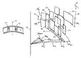
- FIG. 4is a perspective view of a plurality of irregular incisions located inside the stroma of an eye, shown relative to the visual axis of an eye in accordance with the present invention.
- a laser unit for use with the present inventionis shown and is designated 10 .
- the laser unit 10is of a type well known in the pertinent art for generating a pulsed femtosecond laser beam that is capable of performing Laser Induced Optical Breakdown (LIOB) on stromal tissue in a cornea 12 .
- LIOBLaser Induced Optical Breakdown
- the cornea 12defines a visual axis 14 , and it has an anterior surface 16 .
- the laser unit 10is used to weaken stromal tissue in the cornea 12 for the purpose of providing a refractive correction.
- FIG. 2Ashows a pattern 18 of regular incisions in the cornea 12 made for this purpose. More specifically, the pattern 18 will typically have a plurality of concentric cylindrical incisions that are centered on the visual axis 14 . The procedure and consequence of creating the pattern 18 of regular incisions is fully disclosed in the co-pending '202 Appln. mentioned above.
- FIG. 2Bshows the presentation of a pattern 20 of irregular incisions as intended for the present invention.
- the pattern 20is a pseudo-random pattern wherein dimensions and locations of incisions within the pattern 20 are based on a statistical distribution that is generated by a random number generator (not shown). Although both the pattern 18 and the pattern 20 are selected to achieve a same refractive correction for cornea 12 , the pattern 20 is specifically intended to do so while minimizing any adverse side effects that might otherwise result.
- the pattern 20includes a plurality of irregular incisions, of which the irregular incision 22 is exemplary.
- the irregular incision 22is defined by an arc width “d ⁇ m ” and by a length “dz l ”.
- the location of the irregular incision 22is established within its arc width d ⁇ by a characteristic radial distance increment “dr n ”.
- the radial distance dr ne.g.
- the length dz(e.g. of incision 24 ) is measured along a line 26 that is substantially perpendicular to the anterior surface 16 of the cornea 12 and substantially parallel to the visual axis 14 .
- Dimensional parameters for the irregular incision 22 shown in FIG. 4are selected within predetermined ranges.
- the arc width d ⁇ m for the irregular incision 22 and for the irregular incision 24is the same, and is in a range between approximately 8° and 12°.
- m1 ⁇ 36
- ⁇ d ⁇ m360°.
- all incisions in a same level “I” and having a same d ⁇ mwill also have a same length dz l .
- I1 ⁇ 10 (i.e. there are ten levels), with each dz l being in a range of 30 ⁇ m to 50 ⁇ m.
- the irregular incision 30is located in the arc d ⁇ 1
- the irregular incision 22is located in the arc d ⁇ 2
- the irregular incision 28is located in the arc d ⁇ 3 .
- each of the incisions 22 , 28 and 30also have a different characteristic radial increment dr n .
- the irregular incision 22has a radial distance increment dr 1
- the irregular incision 30has a radial distance increment dr′ 1
- the irregular incision 28has a radial distance increment dr′′ 1 .
- the differences between radial distance increments dr 1 , dr′ 1 , and d′′r 1 for the respective irregular incisions 22 , 30 and 28are established to be within a predetermined radial distance of each other. Preferably, this distance is not greater than about 20 microns.
- the distance between irregular incisions with different radial distance increments dr nis preferably greater than approximately 50 ⁇ m.
- dr′ 1 for irregular incision 30will preferably be about 1 mm and dr′ 2 for the irregular incision 32 will be greater than 50 ⁇ m.
- the radial distance increments dr nare additive.
- irregular incision 30is approximately 1 mm radial distance from the visual axis 14
- the irregular incision 32will be at least 1.05 mm distance from the visual axis 14 .
- irregular incisionsthat have the same arc width d ⁇ m , but are in different levels.
- variable parameters d ⁇ , dz, dr, and ⁇are statistically determined by a random number generator to establish the pattern 20 .
Landscapes
- Health & Medical Sciences (AREA)
- Ophthalmology & Optometry (AREA)
- Heart & Thoracic Surgery (AREA)
- Vascular Medicine (AREA)
- Optics & Photonics (AREA)
- Surgery (AREA)
- Engineering & Computer Science (AREA)
- Biomedical Technology (AREA)
- Physics & Mathematics (AREA)
- Nuclear Medicine, Radiotherapy & Molecular Imaging (AREA)
- Life Sciences & Earth Sciences (AREA)
- Animal Behavior & Ethology (AREA)
- General Health & Medical Sciences (AREA)
- Public Health (AREA)
- Veterinary Medicine (AREA)
- Laser Surgery Devices (AREA)
- Prostheses (AREA)
Abstract
Description
- laser unit52
- cornea54
- visual axis56
- anterior surface58
- pattern (regular incision)60
- pattern (irregular incision)62
- irregular incision64
- irregular incision66
- line68
- irregular incision70
- irregular incision72
- irregular incision74
- irregular incision76
- 78
- 80
- 82
- dθ arc width
- dz length
- dr radial distance
Claims (15)
Priority Applications (4)
| Application Number | Priority Date | Filing Date | Title |
|---|---|---|---|
| US12/349,257US8377048B2 (en) | 2009-01-06 | 2009-01-06 | Minimizing the side-effects of refractive corrections using statistically determined irregularities in intrastromal incisions |
| EP09805828AEP2393461A1 (en) | 2009-01-06 | 2009-12-24 | Minimizing the side-effects of refractive corrections using statistically determined irregulariities in the intrastromal incisions |
| PCT/IB2009/007885WO2010079381A1 (en) | 2009-01-06 | 2009-12-24 | Minimizing the side-effects of refractive corrections using statistically determined irregulariities in the intrastromal incisions |
| US12/868,608US20110022037A1 (en) | 2009-01-06 | 2010-08-25 | System and Method for Minimizing the Side Effects of Refractive Corrections Using Line or Dot Cuts for Incisions |
Applications Claiming Priority (1)
| Application Number | Priority Date | Filing Date | Title |
|---|---|---|---|
| US12/349,257US8377048B2 (en) | 2009-01-06 | 2009-01-06 | Minimizing the side-effects of refractive corrections using statistically determined irregularities in intrastromal incisions |
Related Child Applications (1)
| Application Number | Title | Priority Date | Filing Date |
|---|---|---|---|
| US12/868,608Continuation-In-PartUS20110022037A1 (en) | 2009-01-06 | 2010-08-25 | System and Method for Minimizing the Side Effects of Refractive Corrections Using Line or Dot Cuts for Incisions |
Publications (2)
| Publication Number | Publication Date |
|---|---|
| US20100174274A1 US20100174274A1 (en) | 2010-07-08 |
| US8377048B2true US8377048B2 (en) | 2013-02-19 |
Family
ID=42174014
Family Applications (1)
| Application Number | Title | Priority Date | Filing Date |
|---|---|---|---|
| US12/349,257Expired - Fee RelatedUS8377048B2 (en) | 2009-01-06 | 2009-01-06 | Minimizing the side-effects of refractive corrections using statistically determined irregularities in intrastromal incisions |
Country Status (3)
| Country | Link |
|---|---|
| US (1) | US8377048B2 (en) |
| EP (1) | EP2393461A1 (en) |
| WO (1) | WO2010079381A1 (en) |
Families Citing this family (1)
| Publication number | Priority date | Publication date | Assignee | Title |
|---|---|---|---|---|
| WO2014113569A1 (en)* | 2013-01-16 | 2014-07-24 | Amo Development, Llc. | Robust laser cutting methods for ophthalmic surgery |
Citations (22)
| Publication number | Priority date | Publication date | Assignee | Title |
|---|---|---|---|---|
| US4309998A (en) | 1978-06-08 | 1982-01-12 | Aron Rosa Daniele S | Process and apparatus for ophthalmic surgery |
| US4391275A (en) | 1979-11-28 | 1983-07-05 | Lasag Ag | Method for the surgical treatment of the eye |
| US4669466A (en) | 1985-01-16 | 1987-06-02 | Lri L.P. | Method and apparatus for analysis and correction of abnormal refractive errors of the eye |
| US4718418A (en) | 1983-11-17 | 1988-01-12 | Lri L.P. | Apparatus for ophthalmological surgery |
| US4732148A (en) | 1983-11-17 | 1988-03-22 | Lri L.P. | Method for performing ophthalmic laser surgery |
| US4770172A (en) | 1983-11-17 | 1988-09-13 | Lri L.P. | Method of laser-sculpture of the optically used portion of the cornea |
| US4887592A (en) | 1987-06-02 | 1989-12-19 | Hanspeter Loertscher | Cornea laser-cutting apparatus |
| US4907586A (en) | 1988-03-31 | 1990-03-13 | Intelligent Surgical Lasers | Method for reshaping the eye |
| US4941093A (en) | 1985-09-12 | 1990-07-10 | Summit Technology, Inc. | Surface erosion using lasers |
| US4988348A (en) | 1989-05-26 | 1991-01-29 | Intelligent Surgical Lasers, Inc. | Method for reshaping the cornea |
| US5549632A (en) | 1992-10-26 | 1996-08-27 | Novatec Laser Systems, Inc. | Method and apparatus for ophthalmic surgery |
| US5984916A (en) | 1993-04-20 | 1999-11-16 | Lai; Shui T. | Ophthalmic surgical laser and method |
| US5993438A (en) | 1993-11-12 | 1999-11-30 | Escalon Medical Corporation | Intrastromal photorefractive keratectomy |
| US6110166A (en) | 1995-03-20 | 2000-08-29 | Escalon Medical Corporation | Method for corneal laser surgery |
| US6325792B1 (en) | 1991-11-06 | 2001-12-04 | Casimir A. Swinger | Ophthalmic surgical laser and method |
| US6610051B2 (en) | 2001-10-12 | 2003-08-26 | 20/10 Perfect Vision Optische Geraete Gmbh | Device and method for performing refractive surgery |
| US6648877B1 (en)* | 2000-06-30 | 2003-11-18 | Intralase Corp. | Method for custom corneal corrections |
| US20040044355A1 (en) | 2002-08-28 | 2004-03-04 | Nevyas Herbert J. | Minimally invasive corneal surgical procedure for the treatment of hyperopia |
| US20060106372A1 (en)* | 2004-11-12 | 2006-05-18 | Tobias Kuhn | Systems and methods for intrastromal scanning patterns |
| US20080039825A1 (en)* | 2006-07-26 | 2008-02-14 | Lai Shui T | Intrastromal Surgery Correcting Low Order and High Order Aberrations of the Eye |
| US20080306573A1 (en)* | 2007-06-05 | 2008-12-11 | Campin John A | Nomogram computation and application system and method for refractive laser surgery |
| US20080319464A1 (en) | 2007-04-26 | 2008-12-25 | Carl Zeiss Meditec Ag | Re-treatment for ophthalmic correction of refraction |
Family Cites Families (2)
| Publication number | Priority date | Publication date | Assignee | Title |
|---|---|---|---|---|
| EP1977725B1 (en)* | 2007-04-04 | 2010-11-24 | WaveLight GmbH | Device for processing material, in particular refractive eye surgery |
| DE102007053281A1 (en)* | 2007-11-08 | 2009-05-14 | Carl Zeiss Meditec Ag | A treatment device for operative vision correction of an eye, a method for generating control data therefor and methods for surgical correction of defective vision of an eye |
- 2009
- 2009-01-06USUS12/349,257patent/US8377048B2/ennot_activeExpired - Fee Related
- 2009-12-24WOPCT/IB2009/007885patent/WO2010079381A1/enactiveApplication Filing
- 2009-12-24EPEP09805828Apatent/EP2393461A1/ennot_activeWithdrawn
Patent Citations (23)
| Publication number | Priority date | Publication date | Assignee | Title |
|---|---|---|---|---|
| US4309998A (en) | 1978-06-08 | 1982-01-12 | Aron Rosa Daniele S | Process and apparatus for ophthalmic surgery |
| US4391275A (en) | 1979-11-28 | 1983-07-05 | Lasag Ag | Method for the surgical treatment of the eye |
| US4718418A (en) | 1983-11-17 | 1988-01-12 | Lri L.P. | Apparatus for ophthalmological surgery |
| US4732148A (en) | 1983-11-17 | 1988-03-22 | Lri L.P. | Method for performing ophthalmic laser surgery |
| US4770172A (en) | 1983-11-17 | 1988-09-13 | Lri L.P. | Method of laser-sculpture of the optically used portion of the cornea |
| US4669466A (en) | 1985-01-16 | 1987-06-02 | Lri L.P. | Method and apparatus for analysis and correction of abnormal refractive errors of the eye |
| US4721379A (en) | 1985-01-16 | 1988-01-26 | Lri L.P. | Apparatus for analysis and correction of abnormal refractive errors of the eye |
| US4941093A (en) | 1985-09-12 | 1990-07-10 | Summit Technology, Inc. | Surface erosion using lasers |
| US4887592A (en) | 1987-06-02 | 1989-12-19 | Hanspeter Loertscher | Cornea laser-cutting apparatus |
| US4907586A (en) | 1988-03-31 | 1990-03-13 | Intelligent Surgical Lasers | Method for reshaping the eye |
| US4988348A (en) | 1989-05-26 | 1991-01-29 | Intelligent Surgical Lasers, Inc. | Method for reshaping the cornea |
| US6325792B1 (en) | 1991-11-06 | 2001-12-04 | Casimir A. Swinger | Ophthalmic surgical laser and method |
| US5549632A (en) | 1992-10-26 | 1996-08-27 | Novatec Laser Systems, Inc. | Method and apparatus for ophthalmic surgery |
| US5984916A (en) | 1993-04-20 | 1999-11-16 | Lai; Shui T. | Ophthalmic surgical laser and method |
| US5993438A (en) | 1993-11-12 | 1999-11-30 | Escalon Medical Corporation | Intrastromal photorefractive keratectomy |
| US6110166A (en) | 1995-03-20 | 2000-08-29 | Escalon Medical Corporation | Method for corneal laser surgery |
| US6648877B1 (en)* | 2000-06-30 | 2003-11-18 | Intralase Corp. | Method for custom corneal corrections |
| US6610051B2 (en) | 2001-10-12 | 2003-08-26 | 20/10 Perfect Vision Optische Geraete Gmbh | Device and method for performing refractive surgery |
| US20040044355A1 (en) | 2002-08-28 | 2004-03-04 | Nevyas Herbert J. | Minimally invasive corneal surgical procedure for the treatment of hyperopia |
| US20060106372A1 (en)* | 2004-11-12 | 2006-05-18 | Tobias Kuhn | Systems and methods for intrastromal scanning patterns |
| US20080039825A1 (en)* | 2006-07-26 | 2008-02-14 | Lai Shui T | Intrastromal Surgery Correcting Low Order and High Order Aberrations of the Eye |
| US20080319464A1 (en) | 2007-04-26 | 2008-12-25 | Carl Zeiss Meditec Ag | Re-treatment for ophthalmic correction of refraction |
| US20080306573A1 (en)* | 2007-06-05 | 2008-12-11 | Campin John A | Nomogram computation and application system and method for refractive laser surgery |
Also Published As
| Publication number | Publication date |
|---|---|
| WO2010079381A1 (en) | 2010-07-15 |
| EP2393461A1 (en) | 2011-12-14 |
| US20100174274A1 (en) | 2010-07-08 |
Similar Documents
| Publication | Publication Date | Title |
|---|---|---|
| CA2709426C (en) | Method for intrastromal refractive surgery | |
| US7717908B2 (en) | Method patterns for intrastromal refractive surgery | |
| US20140058365A1 (en) | System and Method for Using Compensating Incisions in Intrastromal Refractive Surgery | |
| US20100249761A1 (en) | System and method for altering the optical properties of a material | |
| KR101265402B1 (en) | Computer control for bio-mechanical alteration of the cornea | |
| Daxer et al. | MyoRing treatment for keratoconus: DIOPTEX PocketMaker vs Ziemer LDV for corneal pocket creation | |
| US20110022037A1 (en) | System and Method for Minimizing the Side Effects of Refractive Corrections Using Line or Dot Cuts for Incisions | |
| US8377048B2 (en) | Minimizing the side-effects of refractive corrections using statistically determined irregularities in intrastromal incisions | |
| US8409179B2 (en) | System for performing intrastromal refractive surgery | |
| US8529557B2 (en) | System and method for stray light compensation of corneal cuts | |
| US8366701B2 (en) | System and method for correcting higher order aberrations with changes in intrastromal biomechanical stress distributions | |
| US20240108453A1 (en) | Bioresorbable corneal implants | |
| DE102006003549A1 (en) | Device e.g. for production of control algorithm for laser for ablative treatment of cornea, has software to produce control algorithm for laser treatment on basis of initial parameters of eye which can be corrected |
Legal Events
| Date | Code | Title | Description |
|---|---|---|---|
| AS | Assignment | Owner name:20/10 PERFECT VISION OPERATIONS GMBH, GERMANY Free format text:ASSIGNMENT OF ASSIGNORS INTEREST;ASSIGNOR:BILLE, JOSEF F.;REEL/FRAME:022199/0722 Effective date:20090114 | |
| AS | Assignment | Owner name:TECHNOLAS PERFECT VISION GMBH, GERMANY Free format text:CHANGE OF NAME;ASSIGNOR:20/10 PERFECT VISION OPERATIONS GMBH;REEL/FRAME:023064/0750 Effective date:20090428 | |
| STCF | Information on status: patent grant | Free format text:PATENTED CASE | |
| CC | Certificate of correction | ||
| AS | Assignment | Owner name:BARCLAYS BANK PLC, AS COLLATERAL AGENT, NEW YORK Free format text:SECURITY AGREEMENT;ASSIGNORS:TECHNOLAS PERFECT VISION GMBH;DR. GERHARD MANN CHEM-PHARM. FABRIK GMBH;REEL/FRAME:036400/0711 Effective date:20150819 | |
| FEPP | Fee payment procedure | Free format text:PAT HOLDER NO LONGER CLAIMS SMALL ENTITY STATUS, ENTITY STATUS SET TO UNDISCOUNTED (ORIGINAL EVENT CODE: STOL); ENTITY STATUS OF PATENT OWNER: LARGE ENTITY | |
| FPAY | Fee payment | Year of fee payment:4 | |
| AS | Assignment | Owner name:THE BANK OF NEW YORK MELLON, NEW YORK Free format text:SECURITY INTEREST;ASSIGNOR:TECHNOLAS PERFECT VISION GMBH;REEL/FRAME:043251/0910 Effective date:20170717 | |
| AS | Assignment | Owner name:THE BANK OF NEW YORK MELLON, AS COLLATERAL AGENT, NEW YORK Free format text:SECURITY INTEREST;ASSIGNORS:ATON PHARMA, INC.;BAUSCH & LOMB INCORPORATED;BAUSCH & LOMB PHARMA HOLDINGS CORP.;AND OTHERS;REEL/FRAME:045444/0634 Effective date:20180213 Owner name:BARCLAYS BANK PLC, AS COLLATERAL AGENT, NEW YORK Free format text:SECURITY INTEREST;ASSIGNORS:ATON PHARMA, INC.;BAUSCH & LOMB INCORPORATED;BAUSCH & LOMB PHARMA HOLDINGS CORP.;AND OTHERS;REEL/FRAME:045444/0299 Effective date:20180213 Owner name:THE BANK OF NEW YORK MELLON, AS COLLATERAL AGENT, Free format text:SECURITY INTEREST;ASSIGNORS:ATON PHARMA, INC.;BAUSCH & LOMB INCORPORATED;BAUSCH & LOMB PHARMA HOLDINGS CORP.;AND OTHERS;REEL/FRAME:045444/0634 Effective date:20180213 | |
| AS | Assignment | Owner name:THE BANK OF NEW YORK MELLON, AS COLLATERAL AGENT, Free format text:INTELLECTUAL PROPERTY SECURITY AGREEMENT;ASSIGNORS:BAUSCH HEALTH IRELAND LIMITED;BAUSCH HEALTH COMPANIES INC.;BAUSCH HEALTH, CANADA INC.;AND OTHERS;REEL/FRAME:049672/0652 Effective date:20190701 Owner name:THE BANK OF NEW YORK MELLON, AS COLLATERAL AGENT, NEW YORK Free format text:INTELLECTUAL PROPERTY SECURITY AGREEMENT;ASSIGNORS:BAUSCH HEALTH IRELAND LIMITED;BAUSCH HEALTH COMPANIES INC.;BAUSCH HEALTH, CANADA INC.;AND OTHERS;REEL/FRAME:049672/0652 Effective date:20190701 | |
| FEPP | Fee payment procedure | Free format text:MAINTENANCE FEE REMINDER MAILED (ORIGINAL EVENT CODE: REM.); ENTITY STATUS OF PATENT OWNER: LARGE ENTITY | |
| LAPS | Lapse for failure to pay maintenance fees | Free format text:PATENT EXPIRED FOR FAILURE TO PAY MAINTENANCE FEES (ORIGINAL EVENT CODE: EXP.); ENTITY STATUS OF PATENT OWNER: LARGE ENTITY | |
| STCH | Information on status: patent discontinuation | Free format text:PATENT EXPIRED DUE TO NONPAYMENT OF MAINTENANCE FEES UNDER 37 CFR 1.362 | |
| FP | Lapsed due to failure to pay maintenance fee | Effective date:20210219 | |
| AS | Assignment | Owner name:LABORATOIRE CHAUVIN S.A.S., FRANCE Free format text:RELEASE OF SECURITY INTEREST IN SPECIFIED PATENTS (REEL/FRAME 045444/0299);ASSIGNOR:BARCLAYS BANK PLC;REEL/FRAME:061779/0001 Effective date:20221019 Owner name:PF CONSUMER HEALTHCARE 1 LLC, DELAWARE Free format text:RELEASE OF SECURITY INTEREST IN SPECIFIED PATENTS (REEL/FRAME 045444/0299);ASSIGNOR:BARCLAYS BANK PLC;REEL/FRAME:061779/0001 Effective date:20221019 Owner name:THE UNITED STATES OF AMERICA, AS REPRESENTED BY THE SECRETARY, DEPARTMENT OF HEALTH AND HUMAN SERVICES, MARYLAND Free format text:RELEASE OF SECURITY INTEREST IN SPECIFIED PATENTS (REEL/FRAME 045444/0299);ASSIGNOR:BARCLAYS BANK PLC;REEL/FRAME:061779/0001 Effective date:20221019 Owner name:TECHNOLAS PERFECT VISION GMBH, GERMANY Free format text:RELEASE OF SECURITY INTEREST IN SPECIFIED PATENTS (REEL/FRAME 045444/0299);ASSIGNOR:BARCLAYS BANK PLC;REEL/FRAME:061779/0001 Effective date:20221019 Owner name:BAUSCH & LOMB INCORPORATED, NEW YORK Free format text:RELEASE OF SECURITY INTEREST IN SPECIFIED PATENTS (REEL/FRAME 045444/0299);ASSIGNOR:BARCLAYS BANK PLC;REEL/FRAME:061779/0001 Effective date:20221019 | |
| AS | Assignment | Owner name:THE UNITED STATES OF AMERICA, AS REPRESENTED BY THE SECRETARY, DEPARTMENT OF HEALTH AND HUMAN SERVICES, MARYLAND Free format text:OMNIBUS PATENT SECURITY RELEASE AGREEMENT (REEL/FRAME 045444/0634);ASSIGNOR:THE BANK OF NEW YORK MELLON;REEL/FRAME:061872/0295 Effective date:20221018 Owner name:TECHNOLAS PERFECT VISION GMBH, GERMANY Free format text:OMNIBUS PATENT SECURITY RELEASE AGREEMENT (REEL/FRAME 045444/0634);ASSIGNOR:THE BANK OF NEW YORK MELLON;REEL/FRAME:061872/0295 Effective date:20221018 Owner name:LABORATOIRE CHAUVIN S.A.S., FRANCE Free format text:OMNIBUS PATENT SECURITY RELEASE AGREEMENT (REEL/FRAME 045444/0634);ASSIGNOR:THE BANK OF NEW YORK MELLON;REEL/FRAME:061872/0295 Effective date:20221018 Owner name:BAUSCH & LOMB INCORPORATED, NEW YORK Free format text:OMNIBUS PATENT SECURITY RELEASE AGREEMENT (REEL/FRAME 045444/0634);ASSIGNOR:THE BANK OF NEW YORK MELLON;REEL/FRAME:061872/0295 Effective date:20221018 |