US8377039B2 - Injection site for male luer or other tubular connector - Google Patents
Injection site for male luer or other tubular connectorDownload PDFInfo
- Publication number
- US8377039B2 US8377039B2US10/423,484US42348403AUS8377039B2US 8377039 B2US8377039 B2US 8377039B2US 42348403 AUS42348403 AUS 42348403AUS 8377039 B2US8377039 B2US 8377039B2
- Authority
- US
- United States
- Prior art keywords
- wall
- retention
- connector tube
- connector
- tube
- Prior art date
- Legal status (The legal status is an assumption and is not a legal conclusion. Google has not performed a legal analysis and makes no representation as to the accuracy of the status listed.)
- Active, expires
Links
Images


Classifications
- A—HUMAN NECESSITIES
- A61—MEDICAL OR VETERINARY SCIENCE; HYGIENE
- A61M—DEVICES FOR INTRODUCING MEDIA INTO, OR ONTO, THE BODY; DEVICES FOR TRANSDUCING BODY MEDIA OR FOR TAKING MEDIA FROM THE BODY; DEVICES FOR PRODUCING OR ENDING SLEEP OR STUPOR
- A61M5/00—Devices for bringing media into the body in a subcutaneous, intra-vascular or intramuscular way; Accessories therefor, e.g. filling or cleaning devices, arm-rests
- A61M5/14—Infusion devices, e.g. infusing by gravity; Blood infusion; Accessories therefor
- A61M5/168—Means for controlling media flow to the body or for metering media to the body, e.g. drip meters, counters ; Monitoring media flow to the body
- A61M5/16804—Flow controllers
- A61M5/16813—Flow controllers by controlling the degree of opening of the flow line
- A—HUMAN NECESSITIES
- A61—MEDICAL OR VETERINARY SCIENCE; HYGIENE
- A61M—DEVICES FOR INTRODUCING MEDIA INTO, OR ONTO, THE BODY; DEVICES FOR TRANSDUCING BODY MEDIA OR FOR TAKING MEDIA FROM THE BODY; DEVICES FOR PRODUCING OR ENDING SLEEP OR STUPOR
- A61M39/00—Tubes, tube connectors, tube couplings, valves, access sites or the like, specially adapted for medical use
- A61M39/02—Access sites
- A61M39/04—Access sites having pierceable self-sealing members
- A61M39/045—Access sites having pierceable self-sealing members pre-slit to be pierced by blunt instrument
- A—HUMAN NECESSITIES
- A61—MEDICAL OR VETERINARY SCIENCE; HYGIENE
- A61M—DEVICES FOR INTRODUCING MEDIA INTO, OR ONTO, THE BODY; DEVICES FOR TRANSDUCING BODY MEDIA OR FOR TAKING MEDIA FROM THE BODY; DEVICES FOR PRODUCING OR ENDING SLEEP OR STUPOR
- A61M39/00—Tubes, tube connectors, tube couplings, valves, access sites or the like, specially adapted for medical use
- A61M39/22—Valves or arrangement of valves
- A61M39/26—Valves closing automatically on disconnecting the line and opening on reconnection thereof
Definitions
- Tubing sets for the transfer of medical fluids such as blood or parenteral solutiongenerally comprise flexible plastic tubing with end connectors, which are often luer-type connectors. Injection sites are often carried on the tubing at the ends of, or between the ends of, the tubing sets, comprising an elastomeric diaphragm or bung which is carried in a housing in typically compressed or restrained fashion, so that a needle can resealably penetrate the elastomeric bung and communicate with the interior of the tubular set, for administration of medicines and the withdrawal of medical samples such as blood.
- an injection sitemay also be used to add parenteral solution such as normal saline.
- the Medic® Universal Connector of Medisystems Corporationis a device which is capable of alternatively penetrating an elastomeric diaphragm and joining with a female luer site in the traditional fashion.
- This deviceis not suitable in all uses.
- an injection site on a flexible tube setmay not fit with the Medic design because the Medic device is too long, and impinges the opposite wall of an injection site carried on tubing, having an entry direction perpendicular to the axis of the tubing.
- a connection systemis typically provide for medical devices, including vials and containers for medicine, liquid, or gas, and also injection sites mounted on tubing sets.
- This systemis capable of establishing connection with a male luer, including many ISO compatible, commercially available male luer lock connectors, while it is also preferably capable of providing resealable needle connections.
- Non-luer tapered tubular, tapered or non-tapered probesmay also be connected with the system of this invention.
- an injection siteis provided as part of a medical device which has an interior for containment of a fluid (liquid or gas).
- the medical devicemay be a drug vial or container which utilizes the injection site of this invention, or it can be a tubing set having a main flow path for blood, parenteral solution, gases, or the like, to permit access preferably either by a male luer (luer slip or luer lock) connector or other type of tubular probe, without any intermediate device as in the prior art, such access being to the flow path of the tube set or the interior of any other container.
- access through the injection siteis also available as well by a needle, sharp or blunt.
- An openingis defined into the interior of the medical device, with an elastomeric wall forming a fluid/air tight barrier across said opening, preferably both at positive and negative pressures relative to atmosphere.
- the elastomeric walltypically defines a compressed, or at least constrained, sealed perforation extending at least nearly therethrough.
- This perforationmay be a closed slit with one or many branches, as in the form of a star (*). It may comprise one or more curved slits, or a simple, straight slit.
- a retaining skin or skins made of another material, or wall materialmay prevent complete opening and passage of fluid through the perforation until desired.
- the elastomeric wallis compressed generally at its periphery, to cause pressurization of the perforation so that there is better sealing through the slit and some resistance to opening, as well as sealing to prevent tears around the elastomeric wall.
- wall materialsmay preferably be used that exhibit cohesion or tackiness between the edges of the slit or perforation to hold it together in releasably closed position.
- a retention wallis provided, being generally rigid and nonelastomeric, and located to retain a peripheral portion of the elastomeric wall in its position.
- the peripheral portion of the elastomeric walltypically comprises an outer ring portion that is secured by the retention wall against an annular seat, with a central portion of the elastomeric wall being exposed to the exterior and said opening.
- a portion of the retention wallmay be spaced from the elastomeric wall.
- the retention wallhas a retention zone surrounding said opening, which zone is that part of the retention wall that engages (i.e.
- a connector tubehaving a leading end, which is advanced into said opening to partially displace a central portion of the elastomeric wall into said opening and to open a flow aperture (perforation) through the elastomeric wall, for flow through said wall and connector tube.
- the flow aperturemay be provided by a pre-formed perforation, or the connector tube may have a sharp point or edge to open a flow aperture by cutting through a elastomeric wall which does not have a perforation.
- the retention zonemay be adjacent the elastomeric wall or, alternately, the retention may be placed spaced from the elastomeric wall such that said elastomeric wall is first engaged by the connector tube prior to engaging with the retention zone.
- At least part of the retained connector tube, or the retention zonemay be made of a material of sufficient hardness that the material of the other of the retained connector tube and the retention zone is deformed, temporarily or permanently, by engagement of the two elements, to increase strength of retention (i.e. resistance to disconnection) between the retention zone wall and the connector tube.
- retention resulting from the deformationmay preferably be at least about 100 grams of added force required for such disconnection.
- the retention zonemay deform the connector tube, or vice versa, forming a generally annular indentation and seal therein, to increase the strength of retention between the retention zone and the connector tube.
- the retention zoneis sized to engage and hold the connector tube before the connector tube's leading end penetrates the elastomeric wall, although the connector tube may have advanced sufficiently to push open the perforation in the elastomeric wall.
- the connector tubemay be an ISO standard male luer connector tube that tapers outwardly from its outer or leading end to its inner base.
- the advancing connector tubecomes into engagement with the retention zone, where it may be stopped and held, with material deformation to increase the strength of retention, as the connector tube opens the perforation in the elastomeric wall, but before the leading end or outer tip of the connector tube passes beyond (and preferably before passing into) the slit of the elastomeric wall.
- This preferred conditionis shown in all of the specific embodiments of the drawings, including FIG. 13 , except for FIG. 19 .
- the connector tube and elastomeric wallwill not project far into said opening, which may comprise a blood flow path.
- Such penetrationcan cause turbulence, and can reduce the laminar flow of blood through the blood flow path, which is undesirable.
- such limited penetrationwhile effective to achieve fluid flow through the elastomeric wall, permits a smaller device to be designed and used, compared with systems where full penetration of the elastomeric wall by the connector tube takes place.
- the almost-penetrated elastomeric wallserves as a transition and flow guide between the annular end face of the connector tube and the lumen wall of the adjacent connector bore.
- the flow pathmust exhibit a “step out” from the connector tube to the adjacent bore with significant pressure losses, dependant on the size of the annular face.
- the retention zonemay be ring-shaped, and may have an axial depth (i.e. its dimension in the generally axial direction of the retained connector tube) of no more than about 3 or 4 mm.
- the retention wallmay comprise a transverse wall having an aperture that defines the central opening with a thickness of no more than about 1 mm, so that the edge of the wall that defines the central opening can dig into and deform a portion of the retained connector tube, which connector tube may typically be conical in shape.
- the molding tolerance of the respective partscan be relatively low when compared with a luer connection.
- the retained connector tubeit is generally necessary for the retained connector tube to be positioned in its engaged and retained position with its tip extending into engagement with the elastomeric wall to deflect the elastomeric wall, (or optionally to penetrate it) to open the perforation of the elastomeric wall so that flow communication can take place through the elastomeric wall and the retained connector tube.
- the overall dimensions and the longitudinal position of the connector tubemay have a certain amount of variability (tolerance) and it still may be advanced into engagement with the elastomeric wall, with material deformation taking place by engagement of the connector tube and the retention zone and the necessary position achieved.
- the parts of the deviceare easier to manufacture. Because material is deformed, in some embodiments the retention tube can advance further relative to the retention zone after an initial contact is made, contrary to a male/female luer connection, for example. Thus part tolerance can be less.
- the retained connector tubeis part of an ISO male luer lock connector, where the luer of such connectors only extends a short distance beyond its locking sleeve (such as 2.1 to 3.5 mm), and the advancement into displacement of an elastomeric wall is thus of limited distance.
- the male luerdoes not penetrate through the elastomeric wall, but merely may displace its central portion by a distance sufficient to stretch open the perforation of the elastomeric wall.
- the retention zone surrounding the central openingforcefully engages the male luer of the luer lock connector, with deformation of material resulting through such engagement in one, or the other, or both parts, to increase friction strength of retention between the retention wall and the male luer connector tube, so that the natural resilience of the displaced elastomeric wall does not force expulsion of the connector tube from the retention zone, and a stable, open flow path is created.
- This arrangementis especially good for connectors used in blood flow tubing, since a turbulence and clot promoting male luer tip in the blood flow path is avoided.
- the material of one of the retention zone and the connector tubeis harder than the material of the other part, to facilitate deformation of material as engagement between the connector tube and the retention zone takes place, resulting in increased strength of retention between the retention wall and the connector tube.
- this engaged and retained relationship between the connector tube and the retention zonemay be permanent or temporary, but preferably is of sufficient strength that accidental separation does not take place.
- the retention zoneis harder than the connector tube, having a Shore A durometer of at least about A80.
- the elastomeric wallcomprises a flexible barrier having a width at least as great as its depth positioned across the opening.
- the elastomeric wallis substantially greater in its width than its depth.
- a retention wallmay be positioned to retain the elastomeric wall in sealing relation to said opening.
- the retention walldefines a central opening.
- the elastomeric wallhas a periphery which is retained in fixed position relative to the retention wall, with the retention wall having a retention zone surrounding the central opening to engage and retain the connector tube, which connector tube has a leading end which is advanced into the central opening to press against and, in some embodiments, to displace a central portion of the elastomeric wall.
- This displacement of the elastomeric wallcan open a perforation defined through the elastomeric wall for flow through the wall and connector tube.
- the displacement of the elastomeric wallmay not necessarily open the perforation, but said displacement reduces the pressure resistance to flow at least in the displaced direction of such perforation, while not in the other direction so that pressurized fluid flow can then open the perforation, while normally pressurized fluids cannot open the perforation in the displaced direction.
- the retention zonemay be made of a material of greater hardness than the material of the engaged and retained connector tube so that the retained connector tube is deformed at the retention zone with the generally annular indentation described above by engagement with the retention zone, to increase the strength of retention between the retention wall and the connector tube.
- the retention zonemay be sized to engage and retain the connector tube before the leading end actually enters the perforation.
- the elastomeric wallcomprises a generally flat partition, rather than a partition which is of increased depth by having axially extending members, for example, as in Frank, et al., reissue U.S. Pat. No. 35,841.
- a generally flat partitionmay define a central dome portion if desired, particularly a dome that extends away from the advancing connector tube, which tends to increase the resistance of the perforated elastomeric wall to outward flowing of pressurized fluid.
- the elastomeric wallmay be truly flat, without a dome, if desired. Both of these structures distinguish from flexible barriers that have significant axially extending portions, particularly when such portions extend axially farther than the width of the elastomeric wall.
- the retention zonemay have an axial depth of no more than about 3 or 4 mm, and preferably no more than about 0.6 mm, being sized to engage and hold the connector tube to prevent the leading end thereof from penetrating the perforation, while allowing it to displace a central portion of the elastomeric wall to open the perforation for fluid flow.
- the connector tubeis part of a conventional male luer lock connector which comprises a male luer and a locking ring, the male luer having a tip projecting forwardly beyond the locking ring by no more than about 3.5 mm, preferably complying with ISO specifications.
- the male luerextends through the retention wall central opening sealingly and engages the retention zone carried by the retention wall, when in connection with the device of this invention described above.
- the male luerhas a tip engaging the outer surface of the elastomeric wall, and typically surrounding but not penetrating the perforation defined in the elastomeric wall, while pressing against the elastomeric wall to deflect it inwardly, stretching the perforation toward an open, fluid flow permitting position.
- annular sealmay be formed between the luer tip and the elastomeric wall.
- the locking ringhas an outer end that abuts the retention wall, to prevent further advancement of the male luer at its position of engagement.
- the retention wallmay be of a thickness that positions the male luer beyond its locking ring to deflect the elastomeric wall, to cause stretching of the perforation without allowing the male luer to enter the perforation.
- the retention zonemay be defined by a ring which projects inwardly from a tubular wall that comprises at least part of the retention wall extending perpendicularly, outwardly from the elastomeric wall.
- this tubular wallsurrounds said opening, and extends from an annular cap structure that is also part of the retention wall, and which engages the elastomeric wall at its periphery for retention thereof by pressing the periphery against an annular seat.
- the above described ringmay be of a harder material than the material of the male luer, so that the annular indentation described above is formed in the male luer, increasing strength of retention between the retention wall and the male luer connector tube.
- a plurality of typically radial spacesmay divide the retention zone into separate sections, to provide for greater flexibility of the material of the retention zone, for example, as when the retention wall and its retention zone are made of a metal, such as stainless steel.
- separate tab edges of the retention zonecan engage the connector tube and dig into the material of the connector tube, for firm retention as the tip of the connector tube displaces a central portion of the elastomeric wall and opens a perforation defined therein, for fluid communication through the wall and connector tube.
- the axial distance by which the connector tube of the ISO type displaces the elastomeric wall at its centeris on the order of 1 to 4 mm or sometimes up to 6 mm, in those circumstances where the connector tube does not penetrate through the elastomeric wall perforation, but its front end presses axially against the surface of the elastomeric wall, generally with a closed loop sealing line of pressure positioned on the elastomeric wall, typically radially beyond any portion of the perforation, to provide a closed, preferably fluid tight sealing area between the end of the connector tube and the elastomeric wall.
- the connector tubedoes displace the elastomeric wall further, but without the front end actually penetrating into or beyond the perforation slit, an added seal may be provided between the connector tube side wall and the surface of the elastomeric wall.
- the connector tubemay further displace the elastomeric wall where the front end of the connector tube does penetrate through the perforation of the elastomeric wall, in which case the only seal remaining may be provided between the connector tube and the material defining the perforation.
- the perforationmay be proportioned in some embodiments to provide a 360 degree seal about the connector tube side wall, to provide a seal in a different way from abutment of the tip of the connector tube against the elastomeric wall around the area of the perforation, as discussed in the last paragraph.
- the injection sitedoes not require lubrication of the elastomeric wall with silicone or the like, avoiding the problem of silicone build up in the body.
- the perforationmay comprise a line having a length of about the outer diameter of a male ISO luer at a point adjacent to its minimum diameter end, which line can stretch to provide the desired 360 degree seal as the luer penetrates into the perforation.
- a linehaving a length of about the outer diameter of a male ISO luer at a point adjacent to its minimum diameter end, which line can stretch to provide the desired 360 degree seal as the luer penetrates into the perforation.
- a systemmay be used with a luer slip or a luer lock system.
- upper and lower retention wall portions for retaining the periphery of the elastomeric wallmay respectively define upper and lower central apertures which are positioned generally coaxially with each other.
- the lower central aperture of said openingmay be of greater diameter than the upper central aperture of said retention wall, which facilitates inward displacement of the elastomeric wall by the connector tube, to cause opening of the perforation.
- the retention zonemay then be defined around the central upper aperture.
- the lower central apertureis rarely smaller than a 4 mm inner diameter, and may need to be larger, so as to allow enough “doming downward” of the elastomeric wall to allow sufficient stretching by an ISO male luer which has a leading outer diameter of 3.925 to 4.027 mm.
- the lower retention membermay exist on its own, without an upper retention member, and may be dimensioned to grip the side wall of the connector tube with or without a stretched, displaced elastomeric wall intervening between the connector tube and said lower retention member.
- a tapered-bore tubehaving opposed, longitudinal slots, to permit easier antiseptic swabbing of the interior and the outer face of the elastomeric wall, at the same time providing locking connection to a connector tube.
- a tubemay have a cylindrical bore or a counterbore with or without such slots or it may comprise a female luer or luer lock device.
- connectionit is generally possible to make connection through the injection site of this invention by conventionally using a hypodermic needle, where the sharp needle passes through the body of the elastomeric wall in normal piercing fashion, or through the at least partially preformed slit.
- a hypodermic needlewhere the sharp needle passes through the body of the elastomeric wall in normal piercing fashion, or through the at least partially preformed slit.
- a dull point needleit may be possible for a dull point needle to be used for connection.
- locking systemsmay be utilized as additional structure for connection so that accidental connector separation can be further eliminated as a risk.
- the retention wall and retention zone described abovemay also be made of a fairly resilient material, so that it does some or all of the deformation, when engaging with the retained connector tube, to have the effect of increasing strength of retention between the retention wall and the connector tube.
- Certain IV and hemodialysis setswhich are sold by Japan Medical Supply (JMS) and Kawasumi Laboratories disclose transversely-mounted injection sites which comprise slit elastomeric walls, compressed to reseal.
- the elastomeric wallis partially covered by a top wall in one case, having a central aperture large enough to receive a conventional male luer without a locking ring, which non-locking luer can penetrate completely through the elastomeric wall because of the presence of the slit, and the retention wall provides no restriction against said penetration.
- Neither of these designscan be opened for two way flow by known ISO standard male luer lock connector designs, even with prior penetration of the slit by another object including an ISO standard male luer lock connector.
- the JMS injection siterequires the use of a non-ISO intermediate connector, called a Planecta, that fits to a male luer lock at one end and locks to the external housing of the injection site in a bayonet-type fitting.
- a Planectanon-ISO intermediate connector
- a direct connectioncan be made with an injection site of this invention and a male luer connector, or a male luer lock connector, particularly those of ISO standard, without any need for an intermediate connecting component. Connection can also be made with a sharp or dull needle, not necessarily in any locking or retained relationship.
- the inventive injection sitecontrary to those of the prior art, is thus capable of providing a direct connection at any time with any of the components listed below and the like, so that the injection site can be connected with a wide variety of conventional medical sets and other items, providing a wide compatibility of use of a medical device which carries the injection site of this invention.
- the injection site of this inventionmay be used with an essentially unlimited variety of medical devices, whenever aseptic access is desired.
- the injection sitemay be carried on any of a variety of tube sets in the manner of a T connector as shown in FIGS. 1 and 2 , or at a tube end.
- the injection sitemay be used on an adaptor of various kinds, a stopcock, or as the stopper in any kind of container or vial for typically medical materials.
- the injection site of this inventionmay be carried by any kind of medical device such as syringes, needles, hubs, fluid transport sets, including IV sets, blood tubing sets, blood bag sets, transfer sets, and winged needle sets.
- the injection site of this inventionmay be carried on other medical devices such as medical fluid containers, body access devices, and VACUTAINERTM blood drawing units.
- the injection site of this inventionmay connect with a great number of different devices which carry a connector tube for connection with the injection site of this invention.
- the connector tubemay be carried by a syringe barrel, a tube set, an adapter, a stopcock, a medical fluid container, a vial or the like.
- a preferred injection site of this inventioncomprises a housing having an interior, an opening to the interior, and an elastomeric wall which comprises a barrier across the opening.
- the elastomeric wallhas a central area which defines a sealed perforation extending at least nearly therethrough.
- a thin skin layerremains to provide sealing until it is opened by the connector tube as described above, which typically may be a male luer, either a luer slip or part of a luer lock connector, passing therethrough or sufficiently stretching the thin skin until it tears open.
- This skin layerdoes not need to be an elastomer, and may fracture when the wall is stretched by the pressing connector tube.
- the skin layermay be a plastic coating such as a lacquer paint layer.
- the sealed perforation of the elastomeric wallmay not open at all when connection is made with a connector tube.
- the original seal of the perforationwhich is strong enough to seal against substantial positive or negative pressure, is weakened by the deflection of the elastomeric wall by the connector tube so that, while still closed, its pressure resistance may be lowered in the deflected direction (or both directions).
- flowtakes place typically at relatively low trans-wall fluid pressures normally encountered in medical fluid handling, so that fluids can be passed through the elastomeric wall between the connector tube and the injection site of this invention, but resealing takes place when the pressure on both sides of the elastomeric wall are equalized.
- the shape of the elastomeric wallmay comprise a one-way valve, so that pressurized flow at relatively low pressures normally takes place in only one direction and not in the other direction.
- the connector tubemay be retained by the retention zone in sealing relationship, without the connector tube being in displacing contact with the elastomeric wall.
- a syringefor example, may be left attached to the inventive device without opening the slit or breaking sterility of the connection.
- a connected medical device of this inventionconnected with a male luer lock connector, carries an elastomeric wall covering the first opening and a retention wall as previously described, where the retention wall defines a central opening aligned with the central portion of the elastomeric wall.
- the male luer lock connectorwhich may be an ISO standard connector, has a male luer and a locking ring, with the male luer extending through the retention wall central opening and engaging a retention zone carried by the retention wall to form an annular seal.
- the male luerhas a tip positioned adjacent to an outer surface of the elastomeric wall, but it does not press the elastomeric wall to deflect it inwardly.
- the elastomeric wallwhich defines at least one perforation so that pressurized fluid passing through the male luer can deflect the elastomeric wall inwardly (or outwardly, depending on flow direction) and open the perforation, to permit fluid flow through the perforation and the male luer.
- the elastomeric wallis in contact with portions of the medical device of this invention only at peripheral portions of the wall, contrary to various prior art structures.
- Such a systemwhen connected with a catheter and subjected to lumen pressure, allows opening of the perforation with a minimum of deflection of the elastomeric wall.
- the suction which is generated in the catheter as the elastomeric wall retractsis minimal, since the retraction is minimal.
- less bloodis sucked into an implanted catheter at the end of a dialysis procedure.
- the structure of this inventionmay be similar to previous structures, where the elastomeric wall has a width that is at least as great or preferably greater than its depth, and in which the elastomeric wall consists essentially of a generally flat partition, and where the retention zone may be made of a material harder than the male luer to form a desired, generally annular indentation in the male luer at the retention zone to increase engagement and strength of retention.
- a connected medical device and a male luer lock connectorwhere the structure is similar to that previously described, with the medical device having an interior for containment of fluids, a first opening into the interior and an elastomeric wall comprising a fixedly placed, flexible barrier across the opening, plus a retention wall positioned adjacent to a peripheral portion of the elastomeric wall and defining a central opening aligned with a central portion of the elastomeric wall, to retain the elastomeric wall in position on the medical device.
- the male luer lock connectormay be of a shape conforming to ISO standards, comprising the usual male luer and locking ring in which the tip projects forwardly beyond the locking ring by at least 2.1 mm.
- the male luerextends through the retention wall central opening, and engages a retention zone carried by the retention wall.
- the male luerhas a tip engaging an outer surface of the elastomeric wall, surrounding but not penetrating at least one perforation defined in the elastomeric wall, while pressing against the elastomeric wall to deflect it inwardly, to stretch the perforation toward an open, fluid flow permitting position.
- the locking ringhas an outer end that engages the retention wall to prevent further advancement of the male luer in its locking position, with the retention wall being of a thickness that positions the male luer to deflect the elastomeric wall inwardly to cause the stretching of the perforation without allowing the male luer to enter the perforation.
- the elastomeric wallis in contact with portions of the medical device only at peripheral portions of the wall.
- a retainer capcomprising upper and lower retaining member portions retains the elastomeric wall fixedly in its barrier position across the opening.
- the capdefines an area which is typically annular, and which surrounds the central area of the retainer cap.
- the annular areamay have an inner diameter of about 4 to 8 mm and a first upper, peripheral surface.
- the central area of the elastomeric wallmay have a second, upper surface, with a relative level of the second upper surface being no lower than the level of the first upper surface.
- the outer, annular end of the male connector skirtcan rest against and form the closed loop seal that surrounds the central area, and the central male luer, which projects beyond the connector skirt by a predetermined amount, distorts the elastomeric wall sufficiently to open the sealed perforation for fluid communication through the barrier and to form another annular seal around the perforation.
- the central area of the elastomeric wallmay typically have a thickness of no more than 3 mm.
- the second upper surface (of the central portion of the elastomeric wall)it is generally preferred for the second upper surface (of the central portion of the elastomeric wall) to have a level that is above the level of the first, upper surface of the closed loop area against which the male luer lock connector may abut. This provides more distance of displacement of the elastomeric wall when it is opened, when compared with prior art injection sites.
- a medical valve connectorhaving an interior for containment of fluids; an opening into the interior; an elastomeric wall having at least one closed perforation and comprising a fixedly placed, flexible barrier across said opening, and a retention wall positioned adjacent to a peripheral portion of said elastomeric wall.
- the retention wallalso defines an outwardly extending socket tube portion, having a bore that communicates with a central portion of the elastomeric wall.
- the socket tube portiondefines an annular retention zone along part of the length of the bore of the tube portion.
- the socket tube portionfurther defines an outer, frustoconical bore portion having a first wall angle, and an inner bore portion having a second wall angle that is less than the first wall angle (or it may be parallel to the bore axis-an angle of zero or even counter-board).
- the socket tube portionis proportioned to receive a connector tube and deform at the retention zone by physical contact and physical deformation between the connector tube and at least part of the inner bore portion, to provide good retention between the connector tube, having increased retention strength because of the physical distortion, and also for the purpose of forming an annular seal, which may be fluid tight.
- the connector tubemay be so positioned in the socket tube bore, defining the physical contact, the physical deformation, and the annular seal of the retention zone, while the tip of the connector tube remains spaced from the elastomeric wall.
- the connector tubemay be further manually advanced, with physical deformation in the retention zone, while retaining the annular seal intact as the connector tube advances, to permit the connector tube tip to press against and to deflect the elastomeric wall to open the perforation in a manner similar to previous embodiments.
- this connector and an attached connector tubecan have a plurality of positions, in which the connector tube tip is either spaced from the elastomeric wall, or it deflects the elastomeric wall in a manner similar to the previously described embodiments.
- Each of these positionshas an advantage, so it is advantageous to provide a valved connector system in which both positions can be utilized, and in which the annular seal does not need to be broken as one moves between the two positions.
- the retention zonewhich is defined by the area of physical contact between the two parts, is shallow, typically having a depth of no more than about 4 mm, it becomes possible to achieve the physical deformation of material of the connector tube and/or the socket, which is typically part of the retention wall, so that manual deformation between the parts may take place, resulting in both retention and creation of a liquid tight, annular seal.
- the connector tubemay be further manually advanced after such a seal is formed, to go from a position that is spaced from the elastomeric wall to a position that deflects the elastomeric wall to open the perforation, in a manner similar to the previous embodiments.
- An advantage of the advanced position, where the connector tube deflects the elastomeric wall and stretches open one or more perforations,is that there is little resistance to flow passing through the slit when it is open.
- it may be desired to use this positionwhen a relatively large amount of fluid is being administered to a patient through a syringe, or in the situation where parenteral solution or blood is being administered to a patient by the use of a gravity head, involving low pressures.
- clottingis generally suppressed by administering a bolus of heparin with a syringe to fill the catheter for a storage period between uses.
- the deflected elastomeric wallretracts to its original position, exerting a suction in the catheter, which causes some blood to be drawn into the distal tip of the catheter in the blood vessel. That blood becomes stagnant and tends to clot, which of course is known to be highly undesirable.
- the first administration positionmay be provided, in which the connector tube is spaced from the elastomeric wall while it still participates in an annular seal at the retention zone.
- a small bolus of heparinmay be administered through the catheter to fill it with less deflection of the elastomeric wall, since the fluid passes through the perforation with the minimal deflection.
- this two-positioned valve connector systemcan provide significant advantages of use, especially when working with medical devices connected to conduits that carry blood and are connected to a blood vessel.
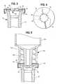
- FIG. 1is a longitudinal sectional view of an embodiment of an injection site of this invention mounted on a tubular section, for connection with other tubular sections to form a tubular set for medical fluids.
- FIG. 2is a longitudinal sectional view of the injection site of FIG. 1 , shown to be in connection with an ISO male luer lock connector carried on a syringe.
- FIG. 3is a longitudinal sectional view of an embodiment of an injection site and connector of this invention, carried on one end of a housing which, in turn, connects with an end of flexible tubing of a medical tube set.
- FIG. 4is a plan view of the retention wall used in FIG. 3 .
- FIG. 5is a longitudinal sectional view of the injection site and connector of FIG. 3 , shown to be in connected relation with an ISO male luer connector which is part of a syringe.
- FIG. 6is a vertical sectional view of another embodiment of this invention in connected relation with an ISO male luer connector which is part of a syringe.
- FIGS. 7-9are longitudinal sectional views of another embodiment of an injection site and connector of this invention.
- FIG. 10is a longitudinal sectional view of another embodiment of an injection site and connector of this invention, shown in separated relation with a conventional luer slip (i.e. non-luer look) connector.
- a conventional luer slipi.e. non-luer look
- FIG. 11is a longitudinal sectional view showing the components of FIG. 10 connected together to provide a flow connection between them.
- FIG. 12is a longitudinal sectional view of another embodiment of the injection site and connector of this invention, with modification, and connected to a conventional luer lock connector.
- FIG. 13is a longitudinal sectional view of another embodiment of the injection site of this invention shown to be connected to a luer lock connector having a rotatable, threaded luer lock sleeve.
- FIG. 14is a longitudinal sectional view of another embodiment of the injection site of this invention, adapted for connection with flexible tubing of a medical fluid flow set.
- FIGS. 15 , 16 and 17are longitudinal, sectional views of another embodiment of the injection site of this invention, comprising a luer lock connector mated to a catheter locking hub, each drawing showing a different situation of use.
- FIG. 18is an enlarged, longitudinal sectional view of the injection site of FIGS. 15-17 .
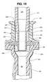
- FIG. 19is a longitudinal, sectional view of another injection site embodiment.
- FIG. 1shows a medical device 10 which comprises both a connector for a male luer or other tube, and an injection site.
- Device 10shows a length of typically rigid tubing 12 which has an interior 14 for containment of fluid.
- Tubing 12may connect at both ends with lengths of flexible set tubing for blood or parenteral solution.
- the sets which carry generally rigid tube 12may be arterial or venous sets for hemodialysis, pheresis, or the like.
- Tube 12defines a lateral opening 16 to the interior and a fixedly placed, flexible barrier 18 , which may be an elastomeric wall extending across the opening.
- a retention wall 20is positioned adjacent to a peripheral portion of elastomeric wall 18 , comprising an outer housing portion which may be a glued, heat welded, or ultrasonic welded to an annular rib 22 of tubular housing 12 .
- Retention wall 20defines a central opening 24 , which exposes a central portion 26 of elastomeric wall 18 .
- Retention wall 20defines an annular retention zone 28 surrounding central opening 24 , to engage and retain a connector tube 34 which is advanced into the central opening, and to form an annular seal, as shown in FIG. 2 .
- FIG. 2shows a male luer lock connector 30 carried on the end of syringe 32 , and defining male luer (connector tube) 34 and threaded locking sleeve 37 .
- luer lock connector 30is of dimensions and other characteristics which are compatible with the standards of the ISO (International Standards Organization) Standards 594-1 and 594-2, as are most luer connectors available for clinical use.
- connector tube 34which is the male luer, advances through central opening 24 .
- connector tube 34displaces elastomeric wall 18 and opens a flow aperture 36 a by expanding preformed slit or perforation 36 , which is previously formed in elastomeric wall 18 .
- tube 34does not enter slit 36 .
- annular retention zone 28 of retention wall 20is made of a plastic or metal which is hard enough to cause deformation of the plastic of male luer connector tube 34 . Because of such deformation, there is an increase in the strength of retention at the junction between retention zone 28 and male luer 34 , so that luer connector 30 is not readily withdrawn from its position shown in FIG.
- syringe 32may be held in flow connection with tube 12 , which is typically part of a medical fluid flow set, so that desired materials may be passed into the flow set which carries tube 12 from syringe 32 .
- Retention wall 20 and annular retention zone 28may be molded of an acrylic material, particularly, Cryolite Med 2 modified acrylic plastic, manufactured by Cryo Industries of Rockaway, N.J., having a Rockwell M hardness of 33. This is harder than the typical polypropylene of which a typical male luer connector may be manufactured, so that deformation of male luer 34 can take place, to strengthen the retention between retention wall 20 and male luer 34 when they are joined together as in FIG. 2 .
- Tubular housing 12may also be made of an acrylic material.
- the flowing fluid in the set which comprises tube 12is blood
- little turbulence and flow blockageis created by the connector of this invention, less than an inwardly projecting spike, for example.
- fluidsmay be added to the set without disrupting a laminar flow path through the set, which facilitates the reduction of blood clotting.
- Syringe 32may then be separated by a positive twist and pull from the injection site comprising retention wall 20 , and elastomeric wall 18 closes slit 36 again for sealing of the system.
- the injection site comprising retention wall 20also permits needle access, both by a sharp needle penetrating through the elastomeric wall 18 , or a dull needle, which can pass through slit 36 .
- the vertical thickness of the annular retention zone 28 which extends around connector tube 34can be about one millimeter or less. Also, an internal, annular thinner edge may be defined at the retention zone 28 to facilitate the deformation of material. That strengthens the retention between retention wall 20 and connector tube 34 , with the annular edge digging into the outer surface of connector tube 34 .
- tube 42which may be a molded structure capable of receiving a flexible tube of a medical tube set for blood or parenteral solution, and serving as an injection site.
- Tube 42may also comprise part of a Y site, a T site, or the like.
- Tube 42terminates in a generally rigid head portion 44 , which comprises an annular support surface 46 for carrying the peripheral portion 48 of elastomeric wall 50 .
- Elastomeric wall 50may have an optional perforation 52 , or it may comprise an intact wall, which is perforated immediately prior to use, for example, either by a separate, pointed instrument or by a tube generally of the shape of a male luer, but with a spike carried on the front end.
- Elastomeric wall 50comprises the fixedly placed flexible barrier, being retained in position by retention wall 54 , which may comprise a metal or plastic cap having a central aperture defined by closed loop retention zone 56 of retention wall 54 . It can be seen that retention zone 56 comprises a small inner, bent, annular portion so that inwardly facing, sharp, annular edges may be defined.
- FIG. 4comprises a plan view of retention wall 54 , showing central opening 58 and the inwardly facing, annular retention zone 56 .
- retention zone 56comprises a material having a hardness of at least about Shore A 90, and divided into separate sections by radial slots or spaces 60 , so that the individual separate retention zone sections 59 exhibit a measure of flexibility, but are still rigid enough to exhibit strong retentive characteristics against a connector tube 34 a with which they engage as the tube enters into central opening 58 , deforming material of connector tube 34 a for strengthened retention.
- FIG. 5Such an entrance by connector tube 34 a is shown in FIG. 5 .
- this luer lock connector 30 ais connected to a syringe 32 a , and comprises the male luer 34 a and a threaded locking sleeve 37 a in conventional manner.
- connectionis made by forcing male luer 34 a inwardly within annular retention zone 56 , until outer, annular end 62 of locking sleeve 37 a abuts retention wall 54 .
- the advancing male luer 34 abeing of frustoconical shape, tightly engages retention zone 56 on such advancement, with deformation of plastic material at the junction area 56 , to increase strength of retention between retention wall 54 and male luer or connector tube 34 a , to provide a locked connection, which may be a releasable lock if desired.
- the male luer 34 , 34 ahas a tip projecting forwardly beyond the locking sleeve or ring 37 , 37 a , and is shown to abut against retention wall 20 , 54 in the respective embodiments.
- the tip of the male luerengages the outer surface of the elastomeric wall to surround but not penetrate the perforation defined in the elastomeric wall, while pressing against the elastomeric wall to deflect it inwardly, stretching the perforation toward an open, fluid flow-permitting position.
- This particular positioning of maximum, advancement of the male luercan be controlled by controlling the thickness of retention wall 20 , 54 , particularly at position 62 , where the outer end of locking sleeve 30 , 30 a engages the retention wall, so that the maximum advanced position of male luer 34 , 34 a can be controlled to achieve the desired results.
- injection site 70is shown, being generally similar in structure and function to the previous injection sites disclosed, except as otherwise specifically described herein.
- Container or syringe 32 bhaving a male luer lock connector 30 b comprising locking sleeve 37 b and male luer 34 b , is shown to be in connection with injection site 70 .
- Container or syringe 32 bmay be identical to the previous containers or syringes 32 and 32 a as shown in previous drawings.
- retention wall 72comprises a plastic plate, carried integrally with a molded cap member 74 , which serves to hold elastomeric wall 50 b in the desired position on annular seat 76 , so that the periphery of elastomeric wall 50 b may be compressed and retained in desired position.
- Wall 50 bis carried on head portion 44 b , which defines a lateral opening 16 b in molded tubular component 12 b which is a tubular structure which may be connected at both ends with lengths of flexible tubing of a flow set for blood or parenteral solutions.
- Cap member 74may be solvent sealed, snapped over, or otherwise bonded to head portion 44 b for nonremovability during normal use.
- cap portion or cover 74has an upstanding sleeve 78 , which is without threads or other structure, for retention of male luer lock member sleeve 37 b .
- male luer 34 bextends through an aperture in retention wall 72 , with retention wall 72 being made of plastic, metal, or the like.
- retention wall 72being made of plastic, metal, or the like.
- ISO standard male luer connector 34 bpasses through the aperture defined by retention wall 72 , its outer wall attains greater dimension by its conical nature, until locking sleeve 37 b enters into engagement with retention wall 72 .
- male luer 34 btypically projecting outwardly beyond locking sleeve 37 b by approximately 2.1-3.5 mm., deflects the central portion of elastomeric wall 50 b to open perforation 80 in a manner similar to the previous embodiments.
- the outer wall of male luer member 34 bforcibly engages retention zone 28 b , to cause the deflection of material at the annular junction site ( 28 b ) to cause deformation of material of one or the other components at the annular junction site 28 b , to increase the strength of the bond between syringe 32 b and connector device 12 b .
- slit 80opens, for flow communication through slit 80 and male luer 34 b to and from the interior of tube 12 b.
- the forward advancement of luer 34 bis governed by the diameter of the aperture defined by retention zone 28 b .
- the degree of distention of elastomeric wall 50 bcan be controlled so that luer 34 b does not overstretch slit 80 and enter into it, when that is desired.
- the formation of an annular seal line 82 between the distal end of male luer 34 b and the upper surface of elastomeric wall 50 bprovides a further, desirable sealing of the flow path through perforation 80 and male luer 34 b.
- retention zone 28 b and male luer 34 bcan cause material deformation, typically in male luer 34 b when annular retention zone 28 b is made of harder material, to provide frictional and mechanical retention between the two pieces, so that they are not easily separated by accident.
- Retention wall 72may be made of a plastic that is harder than the plastic of male luer 34 b , although the opposite may be utilized when desired, to obtain similar results.
- the outer wall of luer lock connector sleeve 37 bcan make contact with the inner wall of upstanding sleeve 78 , to provide frictional securance, and further assurance of retention of the two components together in a locked, flow permitting relationship, so that the contents of syringe 32 b can flow into tubular member 12 b , which may comprise part of a set for the transport of blood or parenteral solutions.
- the circular aperture-defining retention zone 28 b of retention wall 72may be serrated to facilitate a digging-in action for retention of male luer 34 b.
- an injection or access site in accordance with this inventionis shown, which site 66 connects with a conventional luer lock connector 68 , or alternatively can connect with a luer slip connector or a sharp or blunt metal cannula, among other things.
- Injection site 66is shown connected on the end of flexible tubing 71 , which may be connected as part of a tubular parenteral solution or blood set, for example as a Y or T connection with the main flow path of the set.
- This type of valvemay be beneficial for use for the administration of heparin in hemodialysis sets.
- Access site 66comprises a lower housing 73 upon which the periphery of an elastomeric wall 75 is seated, in a manner similar to previous embodiments.
- a cover 77is carried on housing 73 , and bonded thereto in a conventional manner.
- retention wall 79comprises an upstanding wall portion having a pair of diametrically opposed openings 81 , one of which is shown in FIG. 7 , so that a pair of conical wall sections 83 comprise retention wall 79 , and define the central opening 83 that exposes the central portion of elastomeric wall 75 .
- Elastomeric wall 75is peripherally retained between housing 73 and cover 77 in a manner similar to previous embodiments, while the central portion of elastomeric wall 75 is exposed.
- the central portion 84 of elastomeric wall 75defines a dome shape in its normal, unstretched configuration as shown in FIG. 7 (Relative to FIG. 8 ).
- the purpose of this dome shapeis to suppress backflow of fluid through perforated slit 86 when the interior of housing 73 is pressurized relative to the region above slit 86 .
- This pressure resistancecan preferably be on the order of 1500 millimeters of mercury (mm. Hg), so that blood or the like will not normally bleed outwardly from injection site 66 when the set which carries it is filled with blood.
- luer lock connector 68commonly attached to a flexible tube of another medical fluid flow set, has engaged with injection site 66 .
- Male luer portion 88passes into the central opening of retention wall 79 , while connector sheath portion 90 has screw threads which engage the opposed lugs 92 of retention wall 78 , in a generally conventional manner.
- Male luer 88advances to deform and depress elastomeric wall 75 but, in this embodiment, when male luer 88 is in its fully advanced position as shown in FIG.
- FIG. 9which shows the device of FIG. 8 in a similar configuration except for a change in the pressure situation 98 .
- this pressure(such as 80-100 mm. of mercury or more) may be capable of opening slit 86 because of the geometry of elastomeric wall 74 , permitting the flow of fluid through elastomeric wall 75 in the direction of arrow 98 from luer lock connector 68 into tubing 71 , and from there into the fluid flow set to which it is attached. Accordingly, while fluid flow in either direction is not possible at typical pressures up to about 1500 mm Hg in the FIG.
- FIGS. 8 and 9utilize a connector wall 79 having a bore 100 which is of a conical shape of a different and slightly larger angle than the conical shape of male luer 88 .
- a connector wall 79having a bore 100 which is of a conical shape of a different and slightly larger angle than the conical shape of male luer 88 .
- Thisprovides an annular seal, typically less than 4 mm in axial thickness, resulting in a second seal above and beyond annular seal 106 between the tip of male luer 88 and elastomeric wall 75 , and also increases the retention due to the deformation of material in the bonding area 104 .
- Thisis particularly useful if a luer slip connector is used instead of luer lock connector 68 , since an increase in locking retention force of the connection is provided.
- conical bore surface 100may receive a straight, cylindrical connector tube to provide a similar bond, with material distortion in area 104 with such tube.
- surface 100may be cylindrical, and may engage an upper portion of a tapered connector tube to provide a similar, material-deforming bond that is spaced from the elastomeric wall.
- the cracking pressure of perforation 86is decreased by the mating of typically a luer slip or luer lock connector, the latter being shown in FIGS. 8 and 9 , but the slit 86 may still be closed until a sufficient overpressure upstream 98 is applied. Blood is also prevented from passing back into a syringe attached to luer lock connector 68 by means of the blood pump pulsing of a conventional hemodialysis circuit, which may transitorily cause a downstream pressure 94 which is greater than the upstream pressure.
- a purpose of the diametrically opposed openings 81is to provide access for sterile swabbing of the top of elastomeric wall. These apertures are optional, and may be dispensed with, especially in a clinical situation where it is not intended that a connection with injection site 66 is to be made more than once. Swabbing for resterilization is usually needed only in a situation where injection site 66 is used multiple times, since, typically, it will be initially provided to the user in sterile condition.
- an injection site and connector 110comprising a lower housing 112 , which is closed at the top by elastomeric wall 114 having a perforated slit 116 as in previous embodiments.
- Elastomeric wall 114is retained in its position in manner similar to previous embodiments, being held on annular ledge 118 of lower housing 112 by a cover 120 , which acts as the retention wall, as previously discussed, and defines annular retention zone 122 , which, in turn, defines central opening 124 .
- retention zone 122defines a minimum diameter area at its bottom, next to elastomeric wall 114 , with the diameter tapering outwardly as one draws farther away from elastomeric wall 114 .
- Luer slip (i.e. non-luer lock) connector 126may comprise the front end of a syringe 128 , or it may comprise the part of any other desired device, connected to a medical fluid flow set if desired. Luer slip 126 typically meets ISO standards.
- luer slip connector 126is advanced through central opening 124 , with the tapered connector 126 engaging annular retention zone 122 , preferably sealingly, about the periphery of luer slip connector 126 .
- the material of retention wall 20 and retention zone 122may be made of polycarbonate plastic, having a Rockwell hardness of about M 60, and being significantly harder than a typically polypropylene luer slip connector 126 .
- the luer slip connector tube 126is deformed by the harder material of the retention zone 122 , so that the retention zone deforms or digs into the material of luer slip connector 126 , thus increasing the strength of retention between the retention wall 120 and connector tube 126 and stopping the further advancement or taper luer slip connector 126 into said aperture 124 .
- a central portion of elastomeric wall 114is displaced and stretched by the advancing connector tube 126 to stretch open perforated slit 116 , so that flow communication becomes possible between housing 112 and its connected, flexible tube 113 , and syringe 128 .
- the minimum diameter of retention zone 122is adjusted to allow connector tube 126 to penetrate to a depth where not only does the end 130 of connector tube form a first, annular seal at 130 against the upper surface of elastomeric wall 114 , but connector tube 126 can penetrate to such a depth that a second, annular side seal 132 is also formed between elastomeric wall 114 and connector tube 126 , before forward motion of tube 126 is terminated by firm engagement and material deformation between tube 126 and retention zone 122 .
- the diameter of retention zone 122can thus vary the type of connection and seal that is formed between elastomeric wall 114 and tube 126 .
- the permitted depth of penetration of connector tube 88is such that only a single, annular end seal at 106 is provided between the elastomeric wall and the connector tube 88 .
- the minimum diameter of retention zone 122is a little smaller, then that same situation will take place as in FIGS. 8 and 9 .
- FIG. 12shows a connection between injection site/connector 110 a and a conventional luer lock connector 134 , which may be of ISO specification, and may be connected to a syringe 136 , a tubular flow set connection, or any other desired device.
- tapered luer connector 138may engage with the bore of similarly or differently tapered female retention wall locking sleeve 140 , which conventionally locks with the threads 139 of luer connector 134 .
- the bore 142 of locking sleeve 140may be tapered at an angle slightly larger than the 6% luer taper of connector tube 138 , so that, as in FIGS.
- a lower portion 144 of bore 142engages luer connector tube 138 , with deformation of material, while at portion 146 of bore 142 the two surfaces do not deform and may even be slightly spaced.
- retention wall sleeve 140as part of elastomeric wall retention cap 148 , is made of harder material than luer connector tube 138 , but, if desired, the converse can be true, with the deformation of material providing an annular, sealed retention zone at 144 with added resistance to separation.
- the minimum diameter of bore 142is such that male luer 138 may deflect elastomeric wall 114 a (which may be essentially identical to elastomeric wall 114 if desired) to a degree greater than the deflection illustrated in FIG. 11 , opening perforated slit 116 a more widely than in the previous embodiment and providing a deeper annular, peripheral seal 132 a around the side of tube 138 , along with the abutting annular seal 130 a at the end of tube 138 .
- the depth of deflection of the connector tube and the elastomeric wallcan be governed by the diameter of the retention zone 122 , 144 , etc. or in the case of a male luer lock connector, by the extension distance of end of tube 138 beyond end of locking skirt 134 .
- the injection site/connector of this inventionis very tolerant as to dimensional variation in molding, since the system has tolerance for the specific position of advancement of tube 126 , 138 into connector 110 , 110 a .
- the situation of FIG. 2can be created by one diameter of the retention zone; the situation of FIG. 11 created by another such diameter; and the situation of FIG. 12 can be created by a third diameter of the retention zone.
- the depth of penetration of tube 138can be controlled by thickness of retention cap wall 148 .
- Retention wall 140may comprise a complete sleeve, or it may carry slots in a manner similar to that shown in FIG. 7 for the purpose of permitting effective, easy swabbing of the outer surface of the elastomeric wall prior to reuse. Also, as discussed, variation in the depth of penetration by the connector tube may be controlled by adjustment of the diameter of the connector tube.
- injection site/connector 110 bmay be of similar design to the previous connector 110 a .
- a male luer lock connector 150is shown, having a conventional, rotatable, threaded male luer locking sleeve 152 , which is shown to be threadedly engaging opposed lugs 154 , carried on sleeve 156 , which defines an outwardly facing extension of the retention wall.
- Sleeve 156in this embodiment, has no side apertures as in previous embodiments, but comprises an intact sleeve with a tapered bore which may be of slightly larger angle than the tapered outer diameter of the lower tip 158 of connector tube 160 .
- the diameter of retention zone 144 ais adjusted so that tapered tube 158 penetrates to a greater degree than in the previous embodiments, as shown, to widely open perforated slit 116 b of elastomeric wall 114 b , to approximate the diameter of the rest of the flow lumen as found in connected tubing 159 and bore 160 of tapered tubing 158 .
- This embodimentis particularly useful in providing a generally laminar flow path, which is particularly desirable for the flow of blood and the avoidance of clotting.
- a relatively large retention zone 144 a and relatively large annular side seal 162may be provided where the front end of tapered tube 158 passes through elastomeric wall 114 b and partially through the slit.
- the almost-penetrated elastomeric wall 114 bserves as a transition seal and flow guide between the annular end face 163 of the connector tube 158 and the lumen wall 165 of the adjacent bore of connector 110 b .
- the flow pathdefines an annular “step” between the connector tube and the adjacent bore of the female connector, creating significant turbulence and pressure loss, dependent on the size of annular end face 163 .
- a “step”is largely avoided, thus reducing turbulence and pressure loss.
- tapered tube 158still does not penetrate slit 116 b but merely is in contact with the outer wall of elastomeric wall 114 b because the material 169 defining slit 116 b has been deformed outwardly toward the inner side wall of connector 110 b.
- FIGS. 10-13may either carry a retention sleeve such as sleeve 140 in FIGS. 12 and 156 in FIG. 13 , or such a sleeve may be eliminated as in the embodiment of FIGS. 10 and 11 , while still retaining the significant and improved retention of the connection because of the deformation of material achieved in the connection.
- a retention sleevesuch as sleeve 140 in FIGS. 12 and 156 in FIG. 13
- an injection site 200is disclosed, being generally similar in structure and function to previous embodiments, for example, the embodiment of FIG. 6 , except as otherwise shown and described herein, except that the male luer lock connector which would be used to make connection is not specifically shown in FIG. 14 .
- Injection site housing 202has a pair of receptacles 204 for lengths of flexible tubing, to incorporate injection site 200 into a conventional medical set.
- Elastomeric wall 206may be similar to previous counterparts, being retained on housing 202 by retention wall 208 by a conventional adhesive process, heat, or ultrasonic welding.
- Retention wall 208further comprises an outwardly facing tubular socket 210 , which may have a generally cylindrical bore 212 as shown, or an inwardly tapered bore if desired, communicating with elastomeric wall 206 .
- the tubular socket 210 of retention wall 208defines an integral ring 214 projecting inwardly from socket tube 210 , which ring defines the retention zone for sealing, material-distorting contact with a connector tube entering into bore 212 , and typically pressing against and deflecting elastomeric wall 206 to open slit perforation 216 . This deflection is illustrated by dotted line 218 .
- an ISO standard male luermay be used, with the retention zone on ring 214 being very shallow in its depth, typically on the order of 0.25 mm., because of the curved surface of ring 214 which brings only a small amount of the longitudinal distance of ring 214 into actual contact with the male luer or other connector tube. Nevertheless, because of the focused pressure provided by such a small area of the retention zone, material deformation can take place, typically in the connector tube with the material of retention zone 214 being harder, so that a good retention is provided between the retention zone on ring 214 and the connector tube, so that the connector tube will not pop out of its engagement until positively removed. Also, it can be seen that tube 210 has conventional ears or a screw thread 220 , which can be used to lock the connector tube such as a male luer into place, when a device such as a male luer lock connector is used.
- very shallow “blow by” grooves 222may optionally be provided in ring 214 , so that residual antiseptic that is present in the system at the outer surface of elastomeric wall 206 will not be forced inwardly, but rather can bleed outwardly through grooves 222 as a connector tube is advanced into engagement with elastomeric wall 206 .
- These groovesmay be very shallow, preferably having a depth of only about 0.01 inch.
- the remaining portions of the wall surrounding bore 212which are spaced from the retention zone on ring 214 , are also spaced from the connector tube.
- Such a systemcan be made capable of use with an ISO luer lock connector.
- a medical valved connector 230having an interior 232 for containment of fluids, and an opening into the interior which is closed with an elastomeric wall 234 having a perforation 236 as in previous embodiments.
- Retention wall 238compresses the periphery of elastomeric wall 234 against annular seat 241 for securance, in a manner similar to previous embodiments.
- Retention wall 238also comprises an outwardly extending socket tube 242 which has a bore 244 communicating with a central portion of elastomeric wall 234 , and conventional locking lugs 245 .
- a syringe 235is provided, terminating in an ISO male luer lock connector 238 , with the luer 240 of said connector 238 being in physical, annular sealing contact with a shallow retention zone 246 between the male luer 240 and the wall surrounding an inner portion of bore 244 , for retention between luer 240 and the inner bore portion at zone 246 , so that an annular seal is formed.
- valved connector 230an enlarged view of valved connector 230 is shown.
- the bore 244 of socket tube 242defines an outer, frustoconical bore portion 244 a and an inner bore portion 244 b , with the wall angle of inner portion 244 b being less than the wall angle of outer portion 244 a .
- the wall angle of bore portion 244 ais 3° from the longitudinal axis 248
- the wall angle of bore portion 244 bis 0.5° to the same axis.
- inner bore portion 244 bcould be cylindrical if desired or counter bored, i.e. tapered in the opposite direction.
- a male luer 240having a conical taper of its outer wall of essentially 1.72 degrees to axis 248 , enters into bore 244 a , the bore is proportioned so that male luer 240 fits loosely until it passes into inner bore portion 244 b . Since the 1.72 degree taper angle of the male luer 240 is greater than the half degree taper angle of the wall of inner bore portion 244 b , the wall of the male luer expands faster at a given level as it advances past the junction 250 between the inner and outer bore portions 244 a , 244 b .
- the first point of sealing contact between male luer 240 and the borewill take place at junction line 250 as the male luer advances. It may be that the tip portion of the male luer is smaller than the diameter of bore 244 at junction 250 , but as the luer advances, its increasing diameter will engage the plastic material of socket 242 to form the retention zone 246 .
- This retention zonewill start with a line contact at junction 250 , but, as male luer 240 is advanced, material at the retention zone 246 is deformed, and, as male luer 240 is advanced, the area of the retention zone, the seal, and the deformed material increases, since the wall angle of bore portion 244 b is less than the outer wall angle of male luer 240 .
- the wall angleis greater than the outer wall angle of male luer 240 , so sealing contact does not occur.
- retention zone 246will be of relatively little area extending only along a portion of the length of bore 244 .
- greater pressures per square mm.are achieved than for example in a conventional luer connection, so that deformation takes place.
- An adjustability of the distance of penetration of luer 240is possible, until the locking sleeve 239 of luer lock connector 238 abuts against retention wall 238 , ( FIG. 17 ) as described also in previous embodiments, as a means to control the maximum limit of extension of male luer 240 so that it does not penetrate into or through open perforation 236 , in preferred embodiments.
- male luer 240can engage and seal with socket 242 with a variety of positions of advancement, the advantages described above can be achieved, particularly with reference to FIGS. 15-17 .
- male luer 240is only partially advanced into socket 242 , but advanced sufficiently so that an end portion of luer 242 enters into inner bore portion 244 b and a relatively narrow retention zone 246 is formed.
- fluid pressurealone can partly depress elastomeric wall 234 and open perforation 236 , for transfer of fluid into chamber 232 and a connected catheter 252 , which is shown to be conventionally connected to chamber 232 by another male luer lock connector structure 254 and a conventional hub 256 carried on catheter 252 .
- FIG. 16may also show the situation prior to administration of fluid by syringe 236
- FIG. 15may illustrate the situation during such administration.
- syringe 235 or another syringe 235 amay be further advanced into socket 242 to the full extent of advance, in which male luer 240 extends completely through bore 244 , to form an enlarged retention zone 246 a ( FIG. 18 ), where a portion of tapered male luer 240 engages and is typically deformed by the harder material of socket 242 , to form a desired, annular seal at retention zone 246 a .
- perforation 236is forced open, and large volumes of solution may be applied without the resistance to flow that would be found in the configuration of FIG. 15 .
- IV solutionsmay be applied in this manner utilizing a male luer slip or luer lock connector attached to an IV set, for low pressure application of solution or blood to catheter 252 , typically using gravity.
- syringe 235 amay be withdrawn to the configuration of FIG. 16 , closing the system and preventing fluid flow through it, and maintaining a double seal, one at the closed perforation 236 and one at the retention zone 246 .
- catheter 252It may be needed to fill catheter 252 with heparin solution, when it is an indwelling catheter that remains in contact with the blood system of a patient.
- the configuration of FIG. 17has a disadvantage, in that withdrawal of luer 240 permits elastomeric wall 234 to naturally and resiliently withdraw to the configuration of FIG. 16 . This, in turn, causes a suction to be generated in the interior of catheter 252 , which, at its other end, can suck blood into the distal tip of the catheter. This is undesirable, since the blood can be stagnant there and will clot.
- syringe 235 aor another medical device, is withdrawn to the configuration of FIG. 16 .
- syringe 235 amay be removed, and a fresh syringe 235 with the desired heparin solution may be attached into the configuration of FIG. 16 where the tip of male luer 240 is spaced from elastomeric wall 234 .
- pressureis applied by syringe 235 , forcing anticoagulant solution into the lumen of catheter 252 , to “lock” the catheter in an otherwise conventional manner, without as much suck back of blood into the catheter when the luer lock connector 238 is removed, as one would find in the situation of FIG. 17 .
- a medical valve connectorin which a connector tube 240 can occupy a plurality of positions while sealing is maintained, at retention zone 246 , with the different positions having different advantages.
- an injection site 260is shown which is similar in its upper portion 242 a to the injection site of FIG. 18 , but it carries a lower housing 262 which is capable of conventional sealing connection with an end of flexible tubing 264 .
- an elastomeric wall 264rests its peripheral area in annular seat 266 .
- Tubular socket member 242 amay be substantially similar in design to socket member 242 .
- the dimensions of bore 244 and the two different bore sections of differing angular relationshipmay be the same as in the embodiment of FIG. 18 .
- FIG. 19shows how another design of connector tube 272 can be used to provide a sealed, annular connection zone 274 , while at the same time this particular connector tube defines a typically cylindrical forward extension 276 which fully penetrates a perforation in elastomeric wall 264 to stretch and deflect elastomeric wall 264 a , and to provide an open flow path between lumen 278 of connector tube 272 and the interior 280 of housing 262 and flexible tubing 264 .
- outer bore portion 244 amay have a wall angle of about 3°, while the conical section 280 of connector tube 272 may have a typical conical luer taper of essentially 1.72°, to cause binding and formation of annular retention zone 274 as connector tube 272 is advanced. This may take place with deformation of plastic at the retention zone, either the plastic of connector tube 272 or socket 242 a , or both depending upon the hardness of the materials, to cause a significant resistance to disconnection and a solid, annular seal that prevents access to the area of bore 270 outside of extension tube 276 .
- elastomeric wall 264Upon withdrawal of connector tube 272 , elastomeric wall 264 recloses its perforation to provide sealing of the system.
- Inner bore portion 282may typically have a slightly inwardly tapering wall angle of about 1 ⁇ 2°, to form a slightly frustoconical inner surface, or it may be cylindrical.
- the elastomeric wallupon withdrawal of the connector tube, can typically reclose its perforated slit to provide resealing again of the interior of the injection site/connector of this invention.
Landscapes
- Health & Medical Sciences (AREA)
- Heart & Thoracic Surgery (AREA)
- Hematology (AREA)
- Engineering & Computer Science (AREA)
- Anesthesiology (AREA)
- Biomedical Technology (AREA)
- Life Sciences & Earth Sciences (AREA)
- Animal Behavior & Ethology (AREA)
- General Health & Medical Sciences (AREA)
- Public Health (AREA)
- Veterinary Medicine (AREA)
- Pulmonology (AREA)
- Vascular Medicine (AREA)
- Infusion, Injection, And Reservoir Apparatuses (AREA)
- External Artificial Organs (AREA)
Abstract
Description
Claims (44)
Priority Applications (6)
| Application Number | Priority Date | Filing Date | Title |
|---|---|---|---|
| US10/423,484US8377039B2 (en) | 2002-10-04 | 2003-04-25 | Injection site for male luer or other tubular connector |
| PCT/US2003/031354WO2004032707A2 (en) | 2002-10-04 | 2003-10-02 | Injection site for male luer or other tubular connector |
| JP2005501078AJP4739019B2 (en) | 2002-10-04 | 2003-10-02 | Injection point for male luer or other tubular connector |
| AU2003277258AAU2003277258A1 (en) | 2002-10-04 | 2003-10-02 | Injection site for male luer or other tubular connector |
| EP03808128AEP1562657A4 (en) | 2002-10-04 | 2003-10-02 | Injection site for male luer or other tubular connector |
| US13/738,842US8647312B2 (en) | 2002-10-04 | 2013-01-10 | Injection site for male luer or other tubular connector |
Applications Claiming Priority (2)
| Application Number | Priority Date | Filing Date | Title |
|---|---|---|---|
| US10/264,863US7025744B2 (en) | 2002-10-04 | 2002-10-04 | Injection site for male luer or other tubular connector |
| US10/423,484US8377039B2 (en) | 2002-10-04 | 2003-04-25 | Injection site for male luer or other tubular connector |
Related Parent Applications (1)
| Application Number | Title | Priority Date | Filing Date |
|---|---|---|---|
| US10/264,863Continuation-In-PartUS7025744B2 (en) | 2002-10-04 | 2002-10-04 | Injection site for male luer or other tubular connector |
Related Child Applications (1)
| Application Number | Title | Priority Date | Filing Date |
|---|---|---|---|
| US13/738,842DivisionUS8647312B2 (en) | 2002-10-04 | 2013-01-10 | Injection site for male luer or other tubular connector |
Publications (2)
| Publication Number | Publication Date |
|---|---|
| US20040068239A1 US20040068239A1 (en) | 2004-04-08 |
| US8377039B2true US8377039B2 (en) | 2013-02-19 |
Family
ID=32095656
Family Applications (2)
| Application Number | Title | Priority Date | Filing Date |
|---|---|---|---|
| US10/423,484Active2028-09-09US8377039B2 (en) | 2002-10-04 | 2003-04-25 | Injection site for male luer or other tubular connector |
| US13/738,842Expired - LifetimeUS8647312B2 (en) | 2002-10-04 | 2013-01-10 | Injection site for male luer or other tubular connector |
Family Applications After (1)
| Application Number | Title | Priority Date | Filing Date |
|---|---|---|---|
| US13/738,842Expired - LifetimeUS8647312B2 (en) | 2002-10-04 | 2013-01-10 | Injection site for male luer or other tubular connector |
Country Status (5)
| Country | Link |
|---|---|
| US (2) | US8377039B2 (en) |
| EP (1) | EP1562657A4 (en) |
| JP (1) | JP4739019B2 (en) |
| AU (1) | AU2003277258A1 (en) |
| WO (1) | WO2004032707A2 (en) |
Cited By (12)
| Publication number | Priority date | Publication date | Assignee | Title |
|---|---|---|---|---|
| US20130150795A1 (en)* | 2009-02-07 | 2013-06-13 | Merit Medical Systems, Inc | Valved connector |
| US20130231630A1 (en)* | 2003-10-30 | 2013-09-05 | Teva Medical Ltd. | Safety drug handling device |
| US8647312B2 (en)* | 2002-10-04 | 2014-02-11 | Nxstage Medical, Inc. | Injection site for male luer or other tubular connector |
| USD716916S1 (en) | 2012-10-18 | 2014-11-04 | Merit Medical Systems, Inc. | Valved connector assembly |
| US20160074866A1 (en)* | 2014-09-11 | 2016-03-17 | Nabsys, Inc. | Self-sealing pipette septum |
| US20160199634A1 (en)* | 2013-08-21 | 2016-07-14 | Cedic S. R. L. | Needlefree valve device |
| US10022531B2 (en) | 2016-01-21 | 2018-07-17 | Teva Medical Ltd. | Luer lock adaptor |
| US10238855B2 (en) | 2013-11-06 | 2019-03-26 | Fresenius Medical Care Deutschland Gmbh | Connector with seal element and adapted connector parts |
| US10294516B2 (en) | 2013-01-18 | 2019-05-21 | Nabsys 2.0 Llc | Enhanced probe binding |
| US20220001162A1 (en)* | 2018-11-09 | 2022-01-06 | Fresenius Medical Care Deutschland Gmbh | Connector for connecting a container to a dispensing conduit |
| US11274341B2 (en) | 2011-02-11 | 2022-03-15 | NABsys, 2.0 LLC | Assay methods using DNA binding proteins |
| US12023462B2 (en)* | 2022-09-29 | 2024-07-02 | Carefusion 303, Inc. | Fluid connector system |
Families Citing this family (36)
| Publication number | Priority date | Publication date | Assignee | Title |
|---|---|---|---|---|
| KR101122334B1 (en)* | 2004-11-05 | 2012-03-28 | 감브로 룬디아 아베 | Catheter for vascular access and method for manufacturing the same |
| US7241285B1 (en) | 2004-12-06 | 2007-07-10 | Medical Ventures, Inc. | Medical site connection |
| US8641684B2 (en)* | 2005-10-11 | 2014-02-04 | Nxstage Medical, Inc. | Closure for tubular access port |
| US8092414B2 (en)* | 2005-11-09 | 2012-01-10 | Nxstage Medical, Inc. | Diaphragm pressure pod for medical fluids |
| JP4769103B2 (en)* | 2006-03-17 | 2011-09-07 | 日本シャーウッド株式会社 | connector |
| US8062267B2 (en)* | 2006-10-05 | 2011-11-22 | Becton, Dickinson And Company | Vascular access device including a tear-resistant septum |
| US8221363B2 (en) | 2006-10-18 | 2012-07-17 | Baxter Healthcare S.A. | Luer activated device with valve element under tension |
| US7981090B2 (en) | 2006-10-18 | 2011-07-19 | Baxter International Inc. | Luer activated device |
| US7753338B2 (en) | 2006-10-23 | 2010-07-13 | Baxter International Inc. | Luer activated device with minimal fluid displacement |
| DE102007024539A1 (en)* | 2007-05-24 | 2008-11-27 | Fresenius Kabi Deutschland Gmbh | Cap for a container for holding liquids, in particular an enteral nutrient solution and container with such a cap |
| JP5290630B2 (en)* | 2007-06-05 | 2013-09-18 | ニプロ株式会社 | Medical connector and manufacturing method thereof |
| JP5493595B2 (en) | 2008-09-01 | 2014-05-14 | 株式会社ジェイ・エム・エス | Medical port |
| EP2456355B1 (en)* | 2009-07-20 | 2016-09-14 | Optiscan Biomedical Corporation | Adjustable connector and dead space reduction |
| JP2011062300A (en)* | 2009-09-16 | 2011-03-31 | Nippon Sherwood Medical Industries Ltd | Suction catheter and suction catheter set |
| WO2011140073A2 (en)* | 2010-05-03 | 2011-11-10 | Optiscan Biomedical Corporation | Adjustable connector, improved fluid flow and reduced clotting risk |
| US8945082B2 (en)* | 2010-12-14 | 2015-02-03 | Hoffman Neopac Ag | Tube with a female Luer lock fitting |
| US9551625B2 (en) | 2011-05-31 | 2017-01-24 | Nxstage Medical, Inc. | Pressure measurement devices, methods, and systems |
| CN104168928A (en)* | 2012-03-12 | 2014-11-26 | 泰尔茂株式会社 | Blood flow connection device and blood bag system |
| US9737686B2 (en)* | 2012-03-12 | 2017-08-22 | Becton, Dickinson And Company | Catheter adapter port valve |
| ITTO20120601A1 (en)* | 2012-07-09 | 2014-01-10 | Borla Ind | FLOW COMPONENT FOR MEDICAL LINES |
| ES2596519T3 (en)* | 2012-07-13 | 2017-01-10 | Becton, Dickinson And Company Ltd. | Access device to a medical vial with pressure equalization system and closed medication transfer and method of use thereof |
| JP5660347B2 (en)* | 2013-09-18 | 2015-01-28 | ニプロ株式会社 | Medical valve |
| EP2862587A1 (en) | 2013-10-15 | 2015-04-22 | Becton Dickinson France | Tip cap assembly for closing an injection system |
| JP2015098336A (en)* | 2013-11-19 | 2015-05-28 | 日本キム株式会社 | Spout and spouted container |
| EP3079756B1 (en)* | 2013-12-10 | 2019-03-13 | Applied Medical Technology, Inc. | Auto-shutoff coupling |
| CN105873632B (en)* | 2013-12-27 | 2019-10-18 | 株式会社海莱客思 | medical device |
| US20150217094A1 (en)* | 2014-02-05 | 2015-08-06 | Applied Medical Technology, Inc. | Fill Valve |
| JP6382548B2 (en)* | 2014-03-28 | 2018-08-29 | テルモ株式会社 | Medical connector |
| CN205252243U (en)* | 2014-08-08 | 2016-05-25 | 康尔福盛2200公司 | A washing port valve module for air flue adapter |
| JP2017143946A (en)* | 2016-02-16 | 2017-08-24 | ニプロ株式会社 | Needleless port |
| EP3568192A4 (en) | 2017-01-12 | 2021-01-20 | I-V Access Technology, Inc. | Catheter valves |
| CN107261296B (en)* | 2017-07-19 | 2023-05-05 | 桃江县人民医院 | Contrast catheter with adjustable joint and capable of expanding inner hole of sheath tube |
| CN114867517A (en)* | 2019-12-12 | 2022-08-05 | 费森尤斯医疗保健控股公司 | Injection port for connection to a medical fluid container and method of making the same |
| US20230072783A1 (en)* | 2021-09-08 | 2023-03-09 | Alexandria Tassopoulos | Medical Tubing Arrangement Comprising a Valve |
| CN113827312B (en)* | 2021-09-18 | 2023-06-13 | 晨兴(南通)医疗器械有限公司 | Delivery system for pulmonary artery embolectomy |
| US11607525B1 (en) | 2022-06-30 | 2023-03-21 | I-V Access Technology, Inc. | Methods and devices for vascular access |
Citations (171)
| Publication number | Priority date | Publication date | Assignee | Title |
|---|---|---|---|---|
| US3974832A (en) | 1975-01-07 | 1976-08-17 | Vca Corporation | Interchangeable hypodermic needle assemblage |
| US3977403A (en) | 1975-02-24 | 1976-08-31 | The Kendall Company | Catheter adapter |
| US3977400A (en) | 1974-11-29 | 1976-08-31 | Deseret Pharmaceutical Co., Inc. | Catheter placement unit with resilient sleeve and manual sleeve closure |
| US3994293A (en) | 1974-05-07 | 1976-11-30 | Crinospital S.P.A. | Injector assembly for use in transfusions and perfusions |
| US3994294A (en) | 1975-02-28 | 1976-11-30 | Ivac Corporation | Syringe pump valving and motor direction control system |
| US4000739A (en) | 1975-07-09 | 1977-01-04 | Cordis Corporation | Hemostasis cannula |
| US4019512A (en) | 1975-12-04 | 1977-04-26 | Tenczar Francis J | Adhesively activated sterile connector |
| US4063555A (en) | 1975-01-24 | 1977-12-20 | Aktiebolaget Stille-Werner | Cannula assembly |
| US4076285A (en) | 1975-08-01 | 1978-02-28 | Erika, Inc. | Laminar flow connector for conduits |
| US4080965A (en) | 1976-09-30 | 1978-03-28 | Baxter Travenol Laboratories, Inc. | In-line cannula valve assembly |
| US4105187A (en) | 1975-10-09 | 1978-08-08 | Klinger Ag | Sealing system for shutoff units |
| US4106491A (en) | 1975-07-24 | 1978-08-15 | Guerra Luis A | Device for prolonged intravascular infusion |
| US4121585A (en) | 1977-01-24 | 1978-10-24 | Becker Jr Karl E | Anti backflow injection device |
| US4128098A (en) | 1976-12-06 | 1978-12-05 | American Hospital Supply Corporation | Valved spike transfer device |
| US4143853A (en)* | 1977-07-14 | 1979-03-13 | Metatech Corporation | Valve for use with a catheter or the like |
| US4149535A (en) | 1976-05-06 | 1979-04-17 | Gist-Brocades N.V. | Catheter holding device |
| US4161949A (en) | 1977-10-27 | 1979-07-24 | Pennwalt Corporation | Aseptic connector |
| US4177814A (en) | 1978-01-18 | 1979-12-11 | KLI, Incorporated | Self-sealing cannula |
| US4197848A (en) | 1978-01-06 | 1980-04-15 | Baxter Travenol Laboratories, Inc. | Closed urinary irrigation site |
| US4200096A (en) | 1976-06-09 | 1980-04-29 | Guy Charvin | Device for introducing a liquid other than blood in a blood vessel |
| US4201208A (en) | 1977-11-30 | 1980-05-06 | Abbott Laboratories | Sterile connecting device |
| US4219912A (en) | 1978-10-10 | 1980-09-02 | Baxter Travenol Laboratories, Inc. | Injection site having thermoplastically sealed injection port |
| US4240411A (en) | 1977-04-25 | 1980-12-23 | Olympus Optical Co., Ltd. | Device for sealing an endoscope channel |
| US4261357A (en) | 1979-01-29 | 1981-04-14 | Critikon, Inc. | Catheter assembly for intermittent intravenous medicament delivery |
| US4324239A (en) | 1980-06-20 | 1982-04-13 | Whitman Medical Corp. | Safety valve for preventing air embolism and hemorrhage |
| US4326569A (en) | 1980-02-15 | 1982-04-27 | Critikon, Inc. | Stopcock seal |
| US4334551A (en) | 1979-04-30 | 1982-06-15 | Becton Dickinson & Company | Connector |
| US4338933A (en) | 1980-12-22 | 1982-07-13 | Abbott Laboratories | Combination quick disconnect coupling and liquid cutoff valve |
| US4387879A (en)* | 1978-04-19 | 1983-06-14 | Eduard Fresenius Chemisch Pharmazeutische Industrie Kg | Self-sealing connector for use with plastic cannulas and vessel catheters |
| US4429856A (en) | 1981-12-18 | 1984-02-07 | Mallinckrodt, Inc. | Inflation valve |
| US4436519A (en) | 1981-05-28 | 1984-03-13 | Argon Medical Corp. | Removable hemostasis valve |
| US4443219A (en) | 1981-03-10 | 1984-04-17 | C. R. Bard, Inc. | System for aseptically draining a urine bag |
| DE3303718C1 (en) | 1983-02-04 | 1984-10-04 | B. Braun Melsungen Ag, 3508 Melsungen | Injection valve for puncture devices or infusion devices |
| US4475548A (en) | 1982-06-01 | 1984-10-09 | Rudolph Muto | Fitting for endotracheal tube apparatus and method of making the fitting |
| US4508367A (en) | 1979-01-09 | 1985-04-02 | Oreopoulos Dimitrios G | Connector |
| US4511359A (en) | 1982-09-29 | 1985-04-16 | Manresa, Inc. | Sterile connection device |
| US4512766A (en) | 1982-12-08 | 1985-04-23 | Whitman Medical Corporation | Catheter valve |
| US4535820A (en) | 1984-05-24 | 1985-08-20 | Burron Medical Inc. | Normally closed check valve |
| US4559043A (en) | 1984-10-29 | 1985-12-17 | Drs Infusion Systems, Inc. | Assembly with septum fitting for connecting adaptor and fluid tube |
| US4601703A (en) | 1984-01-27 | 1986-07-22 | Intermedicat Gmbh | Injector for an infusion or transfusion system |
| US4610665A (en) | 1983-01-18 | 1986-09-09 | Terumo Kabushiki Kaisha | Medical instrument |
| US4610674A (en) | 1984-09-13 | 1986-09-09 | Terumo Kabushi Kaisha | Catheter introducing instrument |
| US4610469A (en) | 1983-02-02 | 1986-09-09 | Steritech B.V. | Connector assembly for sterile connection or two internally sterile containers of tubings |
| US4614267A (en) | 1983-02-28 | 1986-09-30 | Abbott Laboratories | Dual compartmented container |
| US4629450A (en) | 1984-05-09 | 1986-12-16 | Terumo Corporation | Catheter introducing instrument |
| US4645494A (en) | 1985-10-22 | 1987-02-24 | Renal Systems, Inc. | Peritoneal device system |
| US4649904A (en) | 1986-01-02 | 1987-03-17 | Welch Allyn, Inc. | Biopsy seal |
| US4655752A (en) | 1983-10-24 | 1987-04-07 | Acufex Microsurgical, Inc. | Surgical cannula |
| US4666429A (en) | 1986-02-26 | 1987-05-19 | Intelligent Medicine, Inc. | Infusion device having improved valving apparatus |
| DE3627978A1 (en) | 1985-12-06 | 1987-06-11 | Medizin Labortechnik Veb K | Injection valve |
| US4673393A (en) | 1984-12-28 | 1987-06-16 | Terumo Kabushiki Kaisha | Medical instrument |
| US4673400A (en) | 1986-02-10 | 1987-06-16 | Martin Ivan W | Aseptic connector assembly for conduits for sterile fluids |
| US4683916A (en) | 1986-09-25 | 1987-08-04 | Burron Medical Inc. | Normally closed automatic reflux valve |
| US4745950A (en) | 1985-04-12 | 1988-05-24 | Fresenius Ag | Connector for peritoneal dialysis |
| US4752287A (en) | 1986-12-30 | 1988-06-21 | Bioresearch, Inc. | Syringe check valve |
| US4752292A (en) | 1983-01-24 | 1988-06-21 | Icu Medical, Inc. | Medical connector |
| US4758225A (en) | 1985-11-08 | 1988-07-19 | Pharmacia Limited | Devices for sampling, drainage or infusion of liquids from or to the human or animal body |
| US4765588A (en) | 1986-08-18 | 1988-08-23 | Vernay Laboratories, Inc. | Check valve for use with a syringe |
| US4768568A (en) | 1987-07-07 | 1988-09-06 | Survival Technology, Inc. | Hazardous material vial apparatus providing expansible sealed and filter vented chambers |
| US4769017A (en) | 1985-04-04 | 1988-09-06 | Fath John J | Self-sealing infusion manifold and catheter connector |
| US4786281A (en) | 1985-08-02 | 1988-11-22 | Farmitalia Carlo Erba S.P.A. | Device for connecting one end of a liquid medicament delivery cannula to an apparatus for connecting a syringe to a vial containing the medicament |
| CA1248832A (en) | 1985-07-22 | 1989-01-17 | Francesco Peluso | Antibacterial closure system |
| US4798594A (en) | 1987-09-21 | 1989-01-17 | Cordis Corporation | Medical instrument valve |
| US4809679A (en) | 1986-11-19 | 1989-03-07 | Olympus Optical Co., Ltd. | Forceps plug for endoscopes |
| US4823833A (en) | 1982-06-24 | 1989-04-25 | Baxter Healthcare Corporation | Fluid communication device |
| US4842591A (en) | 1988-01-21 | 1989-06-27 | Luther Ronald B | Connector with one-way septum valve, and assembly |
| US4871356A (en) | 1987-06-27 | 1989-10-03 | B. Braun Melsungen Ag | Catheter device |
| US4874377A (en) | 1988-05-26 | 1989-10-17 | Davis Newgard Revocable Family Living Trust | Self-occluding intravascular cannula assembly |
| US4874378A (en) | 1988-06-01 | 1989-10-17 | Cordis Corporation | Catheter sheath introducer |
| US4895346A (en) | 1988-05-02 | 1990-01-23 | The Kendall Company | Valve assembly |
| US4909798A (en) | 1987-11-12 | 1990-03-20 | Daig Corporation | Universal hemostasis cannula |
| US4917668A (en) | 1988-03-18 | 1990-04-17 | B.. Braun Melsungen Ag | Valve for permanent venous cannulae or for catheter insertion means |
| US4929235A (en) | 1985-07-31 | 1990-05-29 | Universal Medical Instrument Corp. | Self-sealing percutaneous tube introducer |
| US4935010A (en) | 1986-11-20 | 1990-06-19 | Pharmacia Limited | Devices for sampling, drainage or infusion of liquids from or to the human or animal body |
| US4950260A (en) | 1989-11-02 | 1990-08-21 | Safetyject | Medical connector |
| US4954149A (en) | 1989-10-25 | 1990-09-04 | Merlin Instrument Company | Injection septum |
| US4960412A (en) | 1988-04-15 | 1990-10-02 | Universal Medical Instrument Corp. | Catheter introducing system |
| US4981469A (en) | 1988-04-18 | 1991-01-01 | Dij Catheter Corp. | Septum adapter assembly and external needle adapter fitting |
| US4984829A (en) | 1982-04-16 | 1991-01-15 | Nippon Kokan Kabushiki Kaisha | Screw coupling joint |
| US5000745A (en) | 1988-11-18 | 1991-03-19 | Edward Weck Incorporated | Hemostatis valve |
| US5006114A (en) | 1990-04-20 | 1991-04-09 | Rogers Bobby E | Medical valve assembly |
| US5009391A (en) | 1988-05-02 | 1991-04-23 | The Kendall Company | Valve assembly |
| US5041097A (en) | 1990-02-26 | 1991-08-20 | Johnson Gerald W | Intravenous catheter fitting with protective end seal |
| US5060812A (en) | 1990-09-06 | 1991-10-29 | International Medication Systems, Limited | Medication container stopper which can be punctured by nozzle of a hypodermic syringe |
| US5061253A (en) | 1988-11-14 | 1991-10-29 | Nissho Corporation | Fluid-communicating device with valve function |
| US5064416A (en) | 1988-05-26 | 1991-11-12 | Newgard Kent W | Self-occluding intravascular cannula assembly |
| US5080654A (en) | 1989-09-18 | 1992-01-14 | Applied Medical Technology, Inc. | Fluid injection device for intravenous delivery system |
| EP0472088A1 (en) | 1990-08-22 | 1992-02-26 | WEX, Roland | Valve assembly for medical fluid circuits |
| US5092857A (en) | 1991-05-17 | 1992-03-03 | Fleischhacker John J | Hemostasis valve having support shoulders |
| US5100394A (en) | 1988-01-25 | 1992-03-31 | Baxter International Inc. | Pre-slit injection site |
| US5104379A (en) | 1989-04-03 | 1992-04-14 | Olympus Optical Co., Ltd. | Medical instrument and valve to be mounted on a mount piece of that instrument |
| US5108380A (en) | 1990-01-12 | 1992-04-28 | B. Braun Melsungen Ag | Hub member |
| US5114408A (en) | 1990-10-18 | 1992-05-19 | Daig Corporation | Universal hemostasis valve having improved sealing characteristics |
| US5127904A (en) | 1988-08-11 | 1992-07-07 | Loo George D H | Improved needle-less parenteral fluid injector |
| US5135489A (en) | 1988-01-25 | 1992-08-04 | Baxter International Inc. | Pre-slit injection site and tapered cannula |
| US5147333A (en) | 1991-05-13 | 1992-09-15 | Burron Medical Inc. | Needleless injection port with automatic backcheck valve |
| US5158554A (en) | 1988-01-25 | 1992-10-27 | Baxter International Inc. | Pre-slit injection site and associated cannula |
| US5167637A (en) | 1990-11-01 | 1992-12-01 | Sherwood Medical Company | Valve membrane for a catheter introducer hemostatic valve |
| US5178607A (en) | 1987-07-31 | 1993-01-12 | Lynn Lawrence A | Blood aspiration assembly septum and blunt needle aspirator |
| US5184652A (en) | 1991-07-02 | 1993-02-09 | Fan Chin Fu | Universal medication port |
| US5195980A (en) | 1992-01-03 | 1993-03-23 | Thomas Medical Products, Inc. | Hemostatic valve |
| US5199948A (en) | 1991-05-02 | 1993-04-06 | Mcgaw, Inc. | Needleless valve |
| US5201725A (en) | 1991-09-26 | 1993-04-13 | Ivac | Needle free i.v. adapter |
| US5203775A (en) | 1990-09-18 | 1993-04-20 | Medex, Inc. | Needleless connector sample site |
| US5211634A (en) | 1991-08-06 | 1993-05-18 | Vaillancourt Vincent L | Composite seal structure and a coupling arrangement for a cannula |
| US5211638A (en) | 1988-01-25 | 1993-05-18 | Baxter International Inc. | Pre-slit injection site |
| US5215538A (en)* | 1992-02-05 | 1993-06-01 | Abbott Laboratories | Connector-activated in-line valve |
| US5215537A (en) | 1990-09-13 | 1993-06-01 | Lynn Lawrence A | Septum for a blunt cannula |
| US5242393A (en) | 1992-06-18 | 1993-09-07 | Becton, Dickinson And Company | Valved blunt cannula injection site |
| US5242432A (en) | 1991-09-26 | 1993-09-07 | Ivac | Needleless adapter |
| US5250033A (en) | 1992-10-28 | 1993-10-05 | Interventional Thermodynamics, Inc. | Peel-away introducer sheath having proximal fitting |
| US5251873A (en) | 1992-06-04 | 1993-10-12 | Vernay Laboratories, Inc. | Medical coupling site |
| US5269771A (en) | 1993-02-24 | 1993-12-14 | Thomas Medical Products, Inc. | Needleless introducer with hemostatic valve |
| US5279571A (en) | 1991-12-30 | 1994-01-18 | Abbott Laboratories | Access site for fluid delivery system |
| US5295658A (en) | 1987-04-27 | 1994-03-22 | Vernay Laboratories, Inc. | Medical coupling site including slit reinforcing members |
| US5328041A (en) | 1993-06-30 | 1994-07-12 | Abbott Laboratories | Two piece stopper for blunt fluid connector |
| US5336192A (en) | 1991-11-27 | 1994-08-09 | Palestrant Aubrey M | Self-sealing valve device for angiographic catheters |
| US5342316A (en)* | 1991-02-14 | 1994-08-30 | Wallace Henry G | Resealable sampling port |
| US5360413A (en) | 1991-12-06 | 1994-11-01 | Filtertek, Inc. | Needleless access device |
| US5368801A (en) | 1993-01-05 | 1994-11-29 | Vlv Associates | Method of mounting a septum in a connector |
| US5380306A (en) | 1991-11-25 | 1995-01-10 | Vygon | Unitary composite connector for a liquid circuit, in particular for medical applications |
| US5409125A (en) | 1989-12-11 | 1995-04-25 | Aktiebolaget Astra | Unit dose container |
| US5417673A (en) | 1993-01-13 | 1995-05-23 | Medex, Inc. | Whole blood sample needleless sample site |
| US5439451A (en) | 1994-03-22 | 1995-08-08 | B. Braun Medical, Inc. | Capless medical backcheck valve |
| US5441487A (en) | 1993-11-30 | 1995-08-15 | Medex, Inc. | Plastic needleless valve housing for standard male luer locks |
| US5445630A (en) | 1993-07-28 | 1995-08-29 | Richmond; Frank M. | Spike with luer fitting |
| US5453097A (en) | 1994-08-15 | 1995-09-26 | Paradis; Joseph R. | Control of fluid flow |
| EP0674914A1 (en) | 1994-03-03 | 1995-10-04 | Wesley H. Verkaart | Needleless injection site |
| US5456675A (en) | 1993-04-08 | 1995-10-10 | Fresenius Ag | Port cannula arrangement for connection to a port |
| US5465938A (en) | 1990-05-29 | 1995-11-14 | Werge; Robert W. | Universal fluid flow control |
| US5470319A (en) | 1994-06-20 | 1995-11-28 | Critical Device Corporation | Needleless injection site |
| US5474544A (en) | 1994-05-25 | 1995-12-12 | Lynn; Lawrence A. | Luer-receiving medical valve |
| US5501426A (en) | 1992-06-04 | 1996-03-26 | Vernay Laboratories, Inc. | Medical coupling site valve body |
| US5522804A (en) | 1994-02-15 | 1996-06-04 | Lynn; Lawrence A. | Aspiration, mixing, and injection syringe |
| US5533983A (en) | 1993-11-26 | 1996-07-09 | Haining; Michael L. | Valved medical connector |
| US5533708A (en) | 1992-06-04 | 1996-07-09 | Vernay Laboratories, Inc. | Medical coupling site valve body |
| US5540661A (en) | 1994-05-03 | 1996-07-30 | Medex, Inc. | Needleless valve having a covalently bonded lubricious coating |
| US5549651A (en) | 1994-05-25 | 1996-08-27 | Lynn; Lawrence A. | Luer-receiving medical valve and fluid transfer method |
| US5578059A (en) | 1993-11-30 | 1996-11-26 | Medex, Inc. | Anti-reflux valve with environmental barrier |
| DE19546580C1 (en) | 1995-12-13 | 1996-12-12 | Fresenius Ag | Access-piece for airless fluid supply or extraction |
| US5584808A (en) | 1995-06-20 | 1996-12-17 | Healy; Patrick M. | Valve mechanism |
| US5620434A (en) | 1994-03-14 | 1997-04-15 | Brony; Seth K. | Medicine vial link for needleless syringes |
| US5674206A (en) | 1996-07-19 | 1997-10-07 | Benlan Inc. | Intravenous injection site having wipeable septum and valve structure |
| US5685866A (en) | 1991-12-18 | 1997-11-11 | Icu Medical, Inc. | Medical valve and method of use |
| US5702019A (en)* | 1995-09-27 | 1997-12-30 | Becton Dickinson France S.A. | Vial having resealable membrane assembly activated by a medical delivery device |
| US5797897A (en) | 1988-01-25 | 1998-08-25 | Baxter International Inc. | Pre-slit injection site and tapered cannula |
| US5899888A (en) | 1988-01-25 | 1999-05-04 | Baxter International Inc. | Pre-slit injection site and tapered cannula |
| US5921419A (en) | 1998-05-04 | 1999-07-13 | Bracco Research Usa | Universal stopper |
| US5957898A (en) | 1997-05-20 | 1999-09-28 | Baxter International Inc. | Needleless connector |
| US6036171A (en) | 1997-09-17 | 2000-03-14 | Halkey-Roberts Corporation | Swabbable valve assembly |
| US6039718A (en) | 1998-01-20 | 2000-03-21 | Bracco Research Usa | Multiple use universal connector |
| US6039302A (en) | 1996-11-18 | 2000-03-21 | Nypro Inc. | Swabbable luer-activated valve |
| US6048335A (en) | 1994-06-20 | 2000-04-11 | Becton Dickinson & Co. | Needleless injection site |
| US6089541A (en) | 1998-09-10 | 2000-07-18 | Halkey-Roberts Corporation | Valve having a valve body and a deformable stem therein |
| US6123690A (en) | 1998-03-20 | 2000-09-26 | Maersk Medical A/S | Subcutaneous infusion device |
| US6162206A (en) | 1997-12-23 | 2000-12-19 | Baxter International Inc. | Resealable access site |
| US6171287B1 (en) | 1998-05-29 | 2001-01-09 | Lawrence A. Lynn | Luer receiver and method for fluid transfer |
| US6193697B1 (en) | 1987-03-17 | 2001-02-27 | Baxter International Inc. | Pre-slit injection site and tapered cannula |
| US6206861B1 (en) | 1995-03-10 | 2001-03-27 | Critical Device Corporation | Needleless injection site |
| US6245048B1 (en) | 1996-12-16 | 2001-06-12 | Icu Medical, Inc. | Medical valve with positive flow characteristics |
| US6261282B1 (en) | 1997-05-20 | 2001-07-17 | Baxter International Inc. | Needleless connector |
| US6290206B1 (en) | 1997-09-15 | 2001-09-18 | Alaris Medical Systems, Inc. | Needleless valve |
| US20020002351A1 (en) | 1996-11-18 | 2002-01-03 | Cote Andrew L. | Swabbable luer-activated valve |
| WO2002004065A2 (en) | 2000-07-11 | 2002-01-17 | Icu Medical, Inc. | Medical valve with positive flow characteristics |
| EP1217284A1 (en) | 1999-09-16 | 2002-06-26 | Terumo Kabushiki Kaisha | Connector |
| US6416499B2 (en) | 1997-07-30 | 2002-07-09 | Cook Incorporated | Medical fluid flow control valve |
| US6419825B1 (en) | 1998-11-13 | 2002-07-16 | Fresenius Medical Care Deutschland Gmbh | Closure element |
| EP1243285B1 (en) | 1999-12-17 | 2005-04-13 | Terumo Kabushiki Kaisha | Tube connector |
| US7025744B2 (en) | 2002-10-04 | 2006-04-11 | Dsu Medical Corporation | Injection site for male luer or other tubular connector |
| US7056308B2 (en) | 2002-10-04 | 2006-06-06 | Dsu Medical Corporation | Medical device with elastomeric penetrable wall and inner seal |
| EP1211184B1 (en) | 1999-04-20 | 2010-01-20 | JMS Co., Ltd. | Cap for container and adaptor for liquid communication |
Family Cites Families (6)
| Publication number | Priority date | Publication date | Assignee | Title |
|---|---|---|---|---|
| US5295698A (en)* | 1993-01-29 | 1994-03-22 | Fel-Pro Incorporated | Molded plastic gasket having an improved sealing bead |
| US5423097A (en)* | 1993-07-01 | 1995-06-13 | Stryker Corporation | Emergency drop fowler and gatch |
| WO1995003841A1 (en)* | 1993-08-03 | 1995-02-09 | I-Flow Corporation | Valve for filling iv solution bag |
| US6039382A (en)* | 1998-01-05 | 2000-03-21 | Chrysler Corporation | Folding top for a motor vehicle |
| JP3404738B2 (en)* | 2000-09-26 | 2003-05-12 | 株式会社ジェイ・エム・エス | Medical injection port |
| US8377039B2 (en)* | 2002-10-04 | 2013-02-19 | Nxstage Medical, Inc. | Injection site for male luer or other tubular connector |
- 2003
- 2003-04-25USUS10/423,484patent/US8377039B2/enactiveActive
- 2003-10-02AUAU2003277258Apatent/AU2003277258A1/ennot_activeAbandoned
- 2003-10-02JPJP2005501078Apatent/JP4739019B2/ennot_activeExpired - Lifetime
- 2003-10-02WOPCT/US2003/031354patent/WO2004032707A2/enactiveApplication Filing
- 2003-10-02EPEP03808128Apatent/EP1562657A4/ennot_activeWithdrawn
- 2013
- 2013-01-10USUS13/738,842patent/US8647312B2/ennot_activeExpired - Lifetime
Patent Citations (188)
| Publication number | Priority date | Publication date | Assignee | Title |
|---|---|---|---|---|
| US3994293A (en) | 1974-05-07 | 1976-11-30 | Crinospital S.P.A. | Injector assembly for use in transfusions and perfusions |
| US3977400A (en) | 1974-11-29 | 1976-08-31 | Deseret Pharmaceutical Co., Inc. | Catheter placement unit with resilient sleeve and manual sleeve closure |
| US3974832A (en) | 1975-01-07 | 1976-08-17 | Vca Corporation | Interchangeable hypodermic needle assemblage |
| US4063555A (en) | 1975-01-24 | 1977-12-20 | Aktiebolaget Stille-Werner | Cannula assembly |
| US3977403A (en) | 1975-02-24 | 1976-08-31 | The Kendall Company | Catheter adapter |
| US3994294A (en) | 1975-02-28 | 1976-11-30 | Ivac Corporation | Syringe pump valving and motor direction control system |
| US4000739A (en) | 1975-07-09 | 1977-01-04 | Cordis Corporation | Hemostasis cannula |
| US4106491A (en) | 1975-07-24 | 1978-08-15 | Guerra Luis A | Device for prolonged intravascular infusion |
| US4076285A (en) | 1975-08-01 | 1978-02-28 | Erika, Inc. | Laminar flow connector for conduits |
| US4105187A (en) | 1975-10-09 | 1978-08-08 | Klinger Ag | Sealing system for shutoff units |
| US4019512A (en) | 1975-12-04 | 1977-04-26 | Tenczar Francis J | Adhesively activated sterile connector |
| US4149535A (en) | 1976-05-06 | 1979-04-17 | Gist-Brocades N.V. | Catheter holding device |
| US4200096A (en) | 1976-06-09 | 1980-04-29 | Guy Charvin | Device for introducing a liquid other than blood in a blood vessel |
| US4080965A (en) | 1976-09-30 | 1978-03-28 | Baxter Travenol Laboratories, Inc. | In-line cannula valve assembly |
| US4128098A (en) | 1976-12-06 | 1978-12-05 | American Hospital Supply Corporation | Valved spike transfer device |
| US4121585A (en) | 1977-01-24 | 1978-10-24 | Becker Jr Karl E | Anti backflow injection device |
| US4240411A (en) | 1977-04-25 | 1980-12-23 | Olympus Optical Co., Ltd. | Device for sealing an endoscope channel |
| US4143853A (en)* | 1977-07-14 | 1979-03-13 | Metatech Corporation | Valve for use with a catheter or the like |
| US4161949A (en) | 1977-10-27 | 1979-07-24 | Pennwalt Corporation | Aseptic connector |
| US4201208A (en) | 1977-11-30 | 1980-05-06 | Abbott Laboratories | Sterile connecting device |
| US4197848A (en) | 1978-01-06 | 1980-04-15 | Baxter Travenol Laboratories, Inc. | Closed urinary irrigation site |
| US4177814A (en) | 1978-01-18 | 1979-12-11 | KLI, Incorporated | Self-sealing cannula |
| US4387879A (en)* | 1978-04-19 | 1983-06-14 | Eduard Fresenius Chemisch Pharmazeutische Industrie Kg | Self-sealing connector for use with plastic cannulas and vessel catheters |
| US4219912A (en) | 1978-10-10 | 1980-09-02 | Baxter Travenol Laboratories, Inc. | Injection site having thermoplastically sealed injection port |
| US4508367A (en) | 1979-01-09 | 1985-04-02 | Oreopoulos Dimitrios G | Connector |
| US4261357A (en) | 1979-01-29 | 1981-04-14 | Critikon, Inc. | Catheter assembly for intermittent intravenous medicament delivery |
| US4334551A (en) | 1979-04-30 | 1982-06-15 | Becton Dickinson & Company | Connector |
| US4326569A (en) | 1980-02-15 | 1982-04-27 | Critikon, Inc. | Stopcock seal |
| US4324239A (en) | 1980-06-20 | 1982-04-13 | Whitman Medical Corp. | Safety valve for preventing air embolism and hemorrhage |
| US4338933A (en) | 1980-12-22 | 1982-07-13 | Abbott Laboratories | Combination quick disconnect coupling and liquid cutoff valve |
| US4443219A (en) | 1981-03-10 | 1984-04-17 | C. R. Bard, Inc. | System for aseptically draining a urine bag |
| US4436519B1 (en) | 1981-05-28 | 1989-04-04 | ||
| US4436519A (en) | 1981-05-28 | 1984-03-13 | Argon Medical Corp. | Removable hemostasis valve |
| US4429856A (en) | 1981-12-18 | 1984-02-07 | Mallinckrodt, Inc. | Inflation valve |
| US4984829A (en) | 1982-04-16 | 1991-01-15 | Nippon Kokan Kabushiki Kaisha | Screw coupling joint |
| US4475548A (en) | 1982-06-01 | 1984-10-09 | Rudolph Muto | Fitting for endotracheal tube apparatus and method of making the fitting |
| US4823833A (en) | 1982-06-24 | 1989-04-25 | Baxter Healthcare Corporation | Fluid communication device |
| US4511359A (en) | 1982-09-29 | 1985-04-16 | Manresa, Inc. | Sterile connection device |
| US4512766A (en) | 1982-12-08 | 1985-04-23 | Whitman Medical Corporation | Catheter valve |
| US4610665A (en) | 1983-01-18 | 1986-09-09 | Terumo Kabushiki Kaisha | Medical instrument |
| US4752292A (en) | 1983-01-24 | 1988-06-21 | Icu Medical, Inc. | Medical connector |
| US4610469A (en) | 1983-02-02 | 1986-09-09 | Steritech B.V. | Connector assembly for sterile connection or two internally sterile containers of tubings |
| DE3303718C1 (en) | 1983-02-04 | 1984-10-04 | B. Braun Melsungen Ag, 3508 Melsungen | Injection valve for puncture devices or infusion devices |
| US4614267A (en) | 1983-02-28 | 1986-09-30 | Abbott Laboratories | Dual compartmented container |
| US4655752A (en) | 1983-10-24 | 1987-04-07 | Acufex Microsurgical, Inc. | Surgical cannula |
| US4601703A (en) | 1984-01-27 | 1986-07-22 | Intermedicat Gmbh | Injector for an infusion or transfusion system |
| US4629450A (en) | 1984-05-09 | 1986-12-16 | Terumo Corporation | Catheter introducing instrument |
| US4535820A (en) | 1984-05-24 | 1985-08-20 | Burron Medical Inc. | Normally closed check valve |
| US4610674A (en) | 1984-09-13 | 1986-09-09 | Terumo Kabushi Kaisha | Catheter introducing instrument |
| US4559043A (en) | 1984-10-29 | 1985-12-17 | Drs Infusion Systems, Inc. | Assembly with septum fitting for connecting adaptor and fluid tube |
| US4673393A (en) | 1984-12-28 | 1987-06-16 | Terumo Kabushiki Kaisha | Medical instrument |
| US4769017A (en) | 1985-04-04 | 1988-09-06 | Fath John J | Self-sealing infusion manifold and catheter connector |
| US4745950A (en) | 1985-04-12 | 1988-05-24 | Fresenius Ag | Connector for peritoneal dialysis |
| CA1248832A (en) | 1985-07-22 | 1989-01-17 | Francesco Peluso | Antibacterial closure system |
| US4929235A (en) | 1985-07-31 | 1990-05-29 | Universal Medical Instrument Corp. | Self-sealing percutaneous tube introducer |
| US4786281A (en) | 1985-08-02 | 1988-11-22 | Farmitalia Carlo Erba S.P.A. | Device for connecting one end of a liquid medicament delivery cannula to an apparatus for connecting a syringe to a vial containing the medicament |
| US4645494A (en) | 1985-10-22 | 1987-02-24 | Renal Systems, Inc. | Peritoneal device system |
| US4758225A (en) | 1985-11-08 | 1988-07-19 | Pharmacia Limited | Devices for sampling, drainage or infusion of liquids from or to the human or animal body |
| DE3627978A1 (en) | 1985-12-06 | 1987-06-11 | Medizin Labortechnik Veb K | Injection valve |
| US4649904A (en) | 1986-01-02 | 1987-03-17 | Welch Allyn, Inc. | Biopsy seal |
| US4673400A (en) | 1986-02-10 | 1987-06-16 | Martin Ivan W | Aseptic connector assembly for conduits for sterile fluids |
| US4666429A (en) | 1986-02-26 | 1987-05-19 | Intelligent Medicine, Inc. | Infusion device having improved valving apparatus |
| US4765588A (en) | 1986-08-18 | 1988-08-23 | Vernay Laboratories, Inc. | Check valve for use with a syringe |
| US4683916A (en) | 1986-09-25 | 1987-08-04 | Burron Medical Inc. | Normally closed automatic reflux valve |
| US4809679A (en) | 1986-11-19 | 1989-03-07 | Olympus Optical Co., Ltd. | Forceps plug for endoscopes |
| US4935010A (en) | 1986-11-20 | 1990-06-19 | Pharmacia Limited | Devices for sampling, drainage or infusion of liquids from or to the human or animal body |
| US4752287A (en) | 1986-12-30 | 1988-06-21 | Bioresearch, Inc. | Syringe check valve |
| US6193697B1 (en) | 1987-03-17 | 2001-02-27 | Baxter International Inc. | Pre-slit injection site and tapered cannula |
| US5295658A (en) | 1987-04-27 | 1994-03-22 | Vernay Laboratories, Inc. | Medical coupling site including slit reinforcing members |
| US4871356A (en) | 1987-06-27 | 1989-10-03 | B. Braun Melsungen Ag | Catheter device |
| US4768568A (en) | 1987-07-07 | 1988-09-06 | Survival Technology, Inc. | Hazardous material vial apparatus providing expansible sealed and filter vented chambers |
| US5178607A (en) | 1987-07-31 | 1993-01-12 | Lynn Lawrence A | Blood aspiration assembly septum and blunt needle aspirator |
| US5466219A (en) | 1987-07-31 | 1995-11-14 | Lawrence A. Lynn | Blood aspiration assembly components and blunt needle aspirators |
| US4798594A (en) | 1987-09-21 | 1989-01-17 | Cordis Corporation | Medical instrument valve |
| US4909798A (en) | 1987-11-12 | 1990-03-20 | Daig Corporation | Universal hemostasis cannula |
| US4842591A (en) | 1988-01-21 | 1989-06-27 | Luther Ronald B | Connector with one-way septum valve, and assembly |
| US6261266B1 (en) | 1988-01-25 | 2001-07-17 | Baxter International Inc. | Pre-slit injection site and tapered cannula |
| US5158554A (en) | 1988-01-25 | 1992-10-27 | Baxter International Inc. | Pre-slit injection site and associated cannula |
| US5171234A (en) | 1988-01-25 | 1992-12-15 | Baxter International, Inc. | Method of effecting a transfer of fluid from a source to a receiver |
| US6213996B1 (en) | 1988-01-25 | 2001-04-10 | Baxter International Inc. | Pre-slit injection site and tapered cannula |
| US5167648A (en) | 1988-01-25 | 1992-12-01 | Baxter International Inc. | Pre-slit injection site and associated cannula |
| US5899888A (en) | 1988-01-25 | 1999-05-04 | Baxter International Inc. | Pre-slit injection site and tapered cannula |
| US5135489A (en) | 1988-01-25 | 1992-08-04 | Baxter International Inc. | Pre-slit injection site and tapered cannula |
| US5871500A (en) | 1988-01-25 | 1999-02-16 | Baxter International Inc. | Pre-slit injection site and tapered cannula |
| US5797897A (en) | 1988-01-25 | 1998-08-25 | Baxter International Inc. | Pre-slit injection site and tapered cannula |
| US5100394A (en) | 1988-01-25 | 1992-03-31 | Baxter International Inc. | Pre-slit injection site |
| US5188620A (en) | 1988-01-25 | 1993-02-23 | Baxter International Inc. | Pre-slit injection site and associated cannula |
| US5211638A (en) | 1988-01-25 | 1993-05-18 | Baxter International Inc. | Pre-slit injection site |
| US4917668A (en) | 1988-03-18 | 1990-04-17 | B.. Braun Melsungen Ag | Valve for permanent venous cannulae or for catheter insertion means |
| US4960412A (en) | 1988-04-15 | 1990-10-02 | Universal Medical Instrument Corp. | Catheter introducing system |
| US4981469A (en) | 1988-04-18 | 1991-01-01 | Dij Catheter Corp. | Septum adapter assembly and external needle adapter fitting |
| US4895346A (en) | 1988-05-02 | 1990-01-23 | The Kendall Company | Valve assembly |
| US5009391A (en) | 1988-05-02 | 1991-04-23 | The Kendall Company | Valve assembly |
| US4874377A (en) | 1988-05-26 | 1989-10-17 | Davis Newgard Revocable Family Living Trust | Self-occluding intravascular cannula assembly |
| US5064416A (en) | 1988-05-26 | 1991-11-12 | Newgard Kent W | Self-occluding intravascular cannula assembly |
| US4874378A (en) | 1988-06-01 | 1989-10-17 | Cordis Corporation | Catheter sheath introducer |
| US5127904A (en) | 1988-08-11 | 1992-07-07 | Loo George D H | Improved needle-less parenteral fluid injector |
| US5061253A (en) | 1988-11-14 | 1991-10-29 | Nissho Corporation | Fluid-communicating device with valve function |
| US5000745A (en) | 1988-11-18 | 1991-03-19 | Edward Weck Incorporated | Hemostatis valve |
| US5104379A (en) | 1989-04-03 | 1992-04-14 | Olympus Optical Co., Ltd. | Medical instrument and valve to be mounted on a mount piece of that instrument |
| US5080654A (en) | 1989-09-18 | 1992-01-14 | Applied Medical Technology, Inc. | Fluid injection device for intravenous delivery system |
| US4954149A (en) | 1989-10-25 | 1990-09-04 | Merlin Instrument Company | Injection septum |
| US4950260A (en) | 1989-11-02 | 1990-08-21 | Safetyject | Medical connector |
| US5409125A (en) | 1989-12-11 | 1995-04-25 | Aktiebolaget Astra | Unit dose container |
| US5108380A (en) | 1990-01-12 | 1992-04-28 | B. Braun Melsungen Ag | Hub member |
| US5041097A (en) | 1990-02-26 | 1991-08-20 | Johnson Gerald W | Intravenous catheter fitting with protective end seal |
| US5006114A (en) | 1990-04-20 | 1991-04-09 | Rogers Bobby E | Medical valve assembly |
| US5465938A (en) | 1990-05-29 | 1995-11-14 | Werge; Robert W. | Universal fluid flow control |
| EP0472088A1 (en) | 1990-08-22 | 1992-02-26 | WEX, Roland | Valve assembly for medical fluid circuits |
| US5060812A (en) | 1990-09-06 | 1991-10-29 | International Medication Systems, Limited | Medication container stopper which can be punctured by nozzle of a hypodermic syringe |
| US5215537A (en) | 1990-09-13 | 1993-06-01 | Lynn Lawrence A | Septum for a blunt cannula |
| US5203775A (en) | 1990-09-18 | 1993-04-20 | Medex, Inc. | Needleless connector sample site |
| USRE35841E (en) | 1990-09-18 | 1998-07-07 | Medex, Inc. | Needleless connector sample site |
| US5114408A (en) | 1990-10-18 | 1992-05-19 | Daig Corporation | Universal hemostasis valve having improved sealing characteristics |
| US5167637A (en) | 1990-11-01 | 1992-12-01 | Sherwood Medical Company | Valve membrane for a catheter introducer hemostatic valve |
| US5342316A (en)* | 1991-02-14 | 1994-08-30 | Wallace Henry G | Resealable sampling port |
| US5199948A (en) | 1991-05-02 | 1993-04-06 | Mcgaw, Inc. | Needleless valve |
| US5147333A (en) | 1991-05-13 | 1992-09-15 | Burron Medical Inc. | Needleless injection port with automatic backcheck valve |
| US5092857A (en) | 1991-05-17 | 1992-03-03 | Fleischhacker John J | Hemostasis valve having support shoulders |
| US5184652A (en) | 1991-07-02 | 1993-02-09 | Fan Chin Fu | Universal medication port |
| US5211634A (en) | 1991-08-06 | 1993-05-18 | Vaillancourt Vincent L | Composite seal structure and a coupling arrangement for a cannula |
| US5242432A (en) | 1991-09-26 | 1993-09-07 | Ivac | Needleless adapter |
| US5201725A (en) | 1991-09-26 | 1993-04-13 | Ivac | Needle free i.v. adapter |
| US5380306A (en) | 1991-11-25 | 1995-01-10 | Vygon | Unitary composite connector for a liquid circuit, in particular for medical applications |
| US5336192A (en) | 1991-11-27 | 1994-08-09 | Palestrant Aubrey M | Self-sealing valve device for angiographic catheters |
| US5360413A (en) | 1991-12-06 | 1994-11-01 | Filtertek, Inc. | Needleless access device |
| US5685866A (en) | 1991-12-18 | 1997-11-11 | Icu Medical, Inc. | Medical valve and method of use |
| US5279571A (en) | 1991-12-30 | 1994-01-18 | Abbott Laboratories | Access site for fluid delivery system |
| US5195980A (en) | 1992-01-03 | 1993-03-23 | Thomas Medical Products, Inc. | Hemostatic valve |
| US5215538A (en)* | 1992-02-05 | 1993-06-01 | Abbott Laboratories | Connector-activated in-line valve |
| US5533708A (en) | 1992-06-04 | 1996-07-09 | Vernay Laboratories, Inc. | Medical coupling site valve body |
| US5295657A (en) | 1992-06-04 | 1994-03-22 | Vernay Laboratories, Inc. | Medical coupling site valve body |
| US5251873B1 (en) | 1992-06-04 | 1995-05-02 | Vernay Laboratories | Medical coupling site. |
| US5251873A (en) | 1992-06-04 | 1993-10-12 | Vernay Laboratories, Inc. | Medical coupling site |
| US5402982A (en) | 1992-06-04 | 1995-04-04 | Vernay Laboratories, Inc. | Medical coupling site valve body |
| US5501426A (en) | 1992-06-04 | 1996-03-26 | Vernay Laboratories, Inc. | Medical coupling site valve body |
| US5242393A (en) | 1992-06-18 | 1993-09-07 | Becton, Dickinson And Company | Valved blunt cannula injection site |
| US5250033A (en) | 1992-10-28 | 1993-10-05 | Interventional Thermodynamics, Inc. | Peel-away introducer sheath having proximal fitting |
| US5368801A (en) | 1993-01-05 | 1994-11-29 | Vlv Associates | Method of mounting a septum in a connector |
| US5417673A (en) | 1993-01-13 | 1995-05-23 | Medex, Inc. | Whole blood sample needleless sample site |
| US5269771A (en) | 1993-02-24 | 1993-12-14 | Thomas Medical Products, Inc. | Needleless introducer with hemostatic valve |
| US5456675A (en) | 1993-04-08 | 1995-10-10 | Fresenius Ag | Port cannula arrangement for connection to a port |
| US5328041A (en) | 1993-06-30 | 1994-07-12 | Abbott Laboratories | Two piece stopper for blunt fluid connector |
| US5445630A (en) | 1993-07-28 | 1995-08-29 | Richmond; Frank M. | Spike with luer fitting |
| US5533983A (en) | 1993-11-26 | 1996-07-09 | Haining; Michael L. | Valved medical connector |
| US5578059A (en) | 1993-11-30 | 1996-11-26 | Medex, Inc. | Anti-reflux valve with environmental barrier |
| US5441487A (en) | 1993-11-30 | 1995-08-15 | Medex, Inc. | Plastic needleless valve housing for standard male luer locks |
| US5522804A (en) | 1994-02-15 | 1996-06-04 | Lynn; Lawrence A. | Aspiration, mixing, and injection syringe |
| US5697915A (en) | 1994-02-15 | 1997-12-16 | Lynn; Lawrence A. | Displacement-activated medical check valve |
| EP0674914A1 (en) | 1994-03-03 | 1995-10-04 | Wesley H. Verkaart | Needleless injection site |
| US5620434A (en) | 1994-03-14 | 1997-04-15 | Brony; Seth K. | Medicine vial link for needleless syringes |
| US5439451A (en) | 1994-03-22 | 1995-08-08 | B. Braun Medical, Inc. | Capless medical backcheck valve |
| US5540661A (en) | 1994-05-03 | 1996-07-30 | Medex, Inc. | Needleless valve having a covalently bonded lubricious coating |
| US5474544A (en) | 1994-05-25 | 1995-12-12 | Lynn; Lawrence A. | Luer-receiving medical valve |
| US5549651A (en) | 1994-05-25 | 1996-08-27 | Lynn; Lawrence A. | Luer-receiving medical valve and fluid transfer method |
| US5470319A (en) | 1994-06-20 | 1995-11-28 | Critical Device Corporation | Needleless injection site |
| US6152900A (en) | 1994-06-20 | 2000-11-28 | Becton, Dickinson And Company | Needleless injection site |
| US6048335A (en) | 1994-06-20 | 2000-04-11 | Becton Dickinson & Co. | Needleless injection site |
| US5453097A (en) | 1994-08-15 | 1995-09-26 | Paradis; Joseph R. | Control of fluid flow |
| US6206861B1 (en) | 1995-03-10 | 2001-03-27 | Critical Device Corporation | Needleless injection site |
| US5584808A (en) | 1995-06-20 | 1996-12-17 | Healy; Patrick M. | Valve mechanism |
| US5702019A (en)* | 1995-09-27 | 1997-12-30 | Becton Dickinson France S.A. | Vial having resealable membrane assembly activated by a medical delivery device |
| DE19546580C1 (en) | 1995-12-13 | 1996-12-12 | Fresenius Ag | Access-piece for airless fluid supply or extraction |
| US5674206A (en) | 1996-07-19 | 1997-10-07 | Benlan Inc. | Intravenous injection site having wipeable septum and valve structure |
| US6039302A (en) | 1996-11-18 | 2000-03-21 | Nypro Inc. | Swabbable luer-activated valve |
| US20020002351A1 (en) | 1996-11-18 | 2002-01-03 | Cote Andrew L. | Swabbable luer-activated valve |
| US6245048B1 (en) | 1996-12-16 | 2001-06-12 | Icu Medical, Inc. | Medical valve with positive flow characteristics |
| US6344033B1 (en) | 1997-05-20 | 2002-02-05 | Baxter International, Inc. | Needleless connector |
| US6261282B1 (en) | 1997-05-20 | 2001-07-17 | Baxter International Inc. | Needleless connector |
| US5957898A (en) | 1997-05-20 | 1999-09-28 | Baxter International Inc. | Needleless connector |
| US6416499B2 (en) | 1997-07-30 | 2002-07-09 | Cook Incorporated | Medical fluid flow control valve |
| US6290206B1 (en) | 1997-09-15 | 2001-09-18 | Alaris Medical Systems, Inc. | Needleless valve |
| US6036171A (en) | 1997-09-17 | 2000-03-14 | Halkey-Roberts Corporation | Swabbable valve assembly |
| US6162206A (en) | 1997-12-23 | 2000-12-19 | Baxter International Inc. | Resealable access site |
| US6039718A (en) | 1998-01-20 | 2000-03-21 | Bracco Research Usa | Multiple use universal connector |
| US6123690A (en) | 1998-03-20 | 2000-09-26 | Maersk Medical A/S | Subcutaneous infusion device |
| US5971181A (en) | 1998-05-04 | 1999-10-26 | Brocco Research Usa Inc. | Multiple use universal stopper |
| US5921419A (en) | 1998-05-04 | 1999-07-13 | Bracco Research Usa | Universal stopper |
| US6171287B1 (en) | 1998-05-29 | 2001-01-09 | Lawrence A. Lynn | Luer receiver and method for fluid transfer |
| US6089541A (en) | 1998-09-10 | 2000-07-18 | Halkey-Roberts Corporation | Valve having a valve body and a deformable stem therein |
| US6419825B1 (en) | 1998-11-13 | 2002-07-16 | Fresenius Medical Care Deutschland Gmbh | Closure element |
| EP1211184B1 (en) | 1999-04-20 | 2010-01-20 | JMS Co., Ltd. | Cap for container and adaptor for liquid communication |
| EP1217284A1 (en) | 1999-09-16 | 2002-06-26 | Terumo Kabushiki Kaisha | Connector |
| EP1243285B1 (en) | 1999-12-17 | 2005-04-13 | Terumo Kabushiki Kaisha | Tube connector |
| WO2002004065A2 (en) | 2000-07-11 | 2002-01-17 | Icu Medical, Inc. | Medical valve with positive flow characteristics |
| US7056308B2 (en) | 2002-10-04 | 2006-06-06 | Dsu Medical Corporation | Medical device with elastomeric penetrable wall and inner seal |
| US7025744B2 (en) | 2002-10-04 | 2006-04-11 | Dsu Medical Corporation | Injection site for male luer or other tubular connector |
| US7569047B2 (en) | 2003-07-03 | 2009-08-04 | Dsu Medical Corporation | Medical device with elastomeric penetrable wall |
Non-Patent Citations (6)
| Title |
|---|
| Drawing labeled Fresenius Connector. |
| European Search Report (dated Sep. 29, 2006; 6 pgs.). |
| Office Action issued Mar. 9, 2011, in European Patent Application No. 04777299. |
| Photograph of JMS Connector with Planecta-Japanese Catalog Page. |
| Publication from ERCI: "Sharps Safety and Needle Stick Prevention"; pp. 95-108 (2001). |
| Supplementary European Search Report issued May 20, 2010, in European Patent Application No. 04777299. |
Cited By (23)
| Publication number | Priority date | Publication date | Assignee | Title |
|---|---|---|---|---|
| US8647312B2 (en)* | 2002-10-04 | 2014-02-11 | Nxstage Medical, Inc. | Injection site for male luer or other tubular connector |
| US11224730B2 (en) | 2003-10-30 | 2022-01-18 | Simplivia Healthcare Ltd. | Safely drug handling device |
| US20130231630A1 (en)* | 2003-10-30 | 2013-09-05 | Teva Medical Ltd. | Safety drug handling device |
| US10953216B2 (en) | 2003-10-30 | 2021-03-23 | Simplivia Healtcare Ltd. | Safety drug handling device |
| US9345641B2 (en)* | 2003-10-30 | 2016-05-24 | Teva Medical Ltd. | Safety drug handling device |
| US9532927B2 (en) | 2003-10-30 | 2017-01-03 | Teva Medical Ltd. | Safety drug handling device |
| US9707386B2 (en)* | 2009-02-07 | 2017-07-18 | Merit Medical Systems, Inc. | Valved connector |
| US20130150795A1 (en)* | 2009-02-07 | 2013-06-13 | Merit Medical Systems, Inc | Valved connector |
| US11274341B2 (en) | 2011-02-11 | 2022-03-15 | NABsys, 2.0 LLC | Assay methods using DNA binding proteins |
| USD716916S1 (en) | 2012-10-18 | 2014-11-04 | Merit Medical Systems, Inc. | Valved connector assembly |
| US10294516B2 (en) | 2013-01-18 | 2019-05-21 | Nabsys 2.0 Llc | Enhanced probe binding |
| US10286203B2 (en)* | 2013-08-21 | 2019-05-14 | Cedic S.R. L. | Needlefree valve device |
| US20160199635A1 (en)* | 2013-08-21 | 2016-07-14 | Cedic s.r.I. | Needlefree valve device |
| US20160199634A1 (en)* | 2013-08-21 | 2016-07-14 | Cedic S. R. L. | Needlefree valve device |
| US10238855B2 (en) | 2013-11-06 | 2019-03-26 | Fresenius Medical Care Deutschland Gmbh | Connector with seal element and adapted connector parts |
| US10583441B2 (en)* | 2014-09-11 | 2020-03-10 | Nabsys 2.0 Llc | Self-sealing pipette septum |
| US20160074866A1 (en)* | 2014-09-11 | 2016-03-17 | Nabsys, Inc. | Self-sealing pipette septum |
| US10022531B2 (en) | 2016-01-21 | 2018-07-17 | Teva Medical Ltd. | Luer lock adaptor |
| US10682505B2 (en) | 2016-01-21 | 2020-06-16 | Simplivia Healthcare Ltd. | Luer lock adaptor |
| US11517731B2 (en) | 2016-01-21 | 2022-12-06 | Simplivia Healthcare Ltd. | Luer lock adaptor |
| US20220001162A1 (en)* | 2018-11-09 | 2022-01-06 | Fresenius Medical Care Deutschland Gmbh | Connector for connecting a container to a dispensing conduit |
| US11890444B2 (en)* | 2018-11-09 | 2024-02-06 | Fresenius Medical Care Deutschland Gmbh | Connector for connecting a container to a dispensing conduit |
| US12023462B2 (en)* | 2022-09-29 | 2024-07-02 | Carefusion 303, Inc. | Fluid connector system |
Also Published As
| Publication number | Publication date |
|---|---|
| WO2004032707A2 (en) | 2004-04-22 |
| US8647312B2 (en) | 2014-02-11 |
| US20130123713A1 (en) | 2013-05-16 |
| AU2003277258A8 (en) | 2004-05-04 |
| EP1562657A4 (en) | 2007-03-14 |
| US20040068239A1 (en) | 2004-04-08 |
| JP2006501976A (en) | 2006-01-19 |
| JP4739019B2 (en) | 2011-08-03 |
| AU2003277258A1 (en) | 2004-05-04 |
| EP1562657A2 (en) | 2005-08-17 |
| WO2004032707A3 (en) | 2005-03-31 |
Similar Documents
| Publication | Publication Date | Title |
|---|---|---|
| US8377039B2 (en) | Injection site for male luer or other tubular connector | |
| US7025744B2 (en) | Injection site for male luer or other tubular connector | |
| US7569047B2 (en) | Medical device with elastomeric penetrable wall | |
| AU709438B2 (en) | Medical adapter having needleless valve and sharpened cannula | |
| US6261266B1 (en) | Pre-slit injection site and tapered cannula | |
| US5154703A (en) | Bloodless catheter | |
| KR101514915B1 (en) | Male member | |
| KR200421308Y1 (en) | Medical valve with fluid escape space | |
| US5135489A (en) | Pre-slit injection site and tapered cannula | |
| US5211638A (en) | Pre-slit injection site | |
| US5100394A (en) | Pre-slit injection site | |
| US8062280B2 (en) | Port assembly for use with needleless connector | |
| US6193697B1 (en) | Pre-slit injection site and tapered cannula | |
| US6605076B1 (en) | Pre-slit injection site and tapered cannula | |
| JPS59228844A (en) | Automatic air passing type coring preventing needle assembly | |
| CN1208356A (en) | Medical valve with fluid escape space | |
| AU731365B2 (en) | Medical adapter | |
| HK1015291B (en) | Medical adapter having needleless valve and sharpened cannula | |
| HK1064059B (en) | Medical adapter having sharpened cannula |
Legal Events
| Date | Code | Title | Description |
|---|---|---|---|
| AS | Assignment | Owner name:DSU MEDICAL CORPORATION, NEVADA Free format text:ASSIGNMENT OF ASSIGNORS INTEREST;ASSIGNORS:UTTERBERG, DAVID S.;SCHNELL, WILLIAM J.;BELL, DAVID;REEL/FRAME:020812/0519;SIGNING DATES FROM 20080319 TO 20080411 Owner name:DSU MEDICAL CORPORATION, NEVADA Free format text:ASSIGNMENT OF ASSIGNORS INTEREST;ASSIGNORS:UTTERBERG, DAVID S.;SCHNELL, WILLIAM J.;BELL, DAVID;SIGNING DATES FROM 20080319 TO 20080411;REEL/FRAME:020812/0519 | |
| AS | Assignment | Owner name:NXSTAGE MEDICAL, INC., MASSACHUSETTS Free format text:RELEASE BY SECURED PARTY;ASSIGNOR:GE BUSINESS FINANCIAL SERVICES INC.;REEL/FRAME:022804/0150 Effective date:20090605 Owner name:EIR MEDICAL, INC., MASSACHUSETTS Free format text:RELEASE BY SECURED PARTY;ASSIGNOR:GE BUSINESS FINANCIAL SERVICES INC.;REEL/FRAME:022804/0150 Effective date:20090605 Owner name:MEDISYSTEMS CORPORATION, MASSACHUSETTS Free format text:RELEASE BY SECURED PARTY;ASSIGNOR:GE BUSINESS FINANCIAL SERVICES INC.;REEL/FRAME:022804/0150 Effective date:20090605 Owner name:MEDISYSTEMS SERVICES CORPORATION, MASSACHUSETTS Free format text:RELEASE BY SECURED PARTY;ASSIGNOR:GE BUSINESS FINANCIAL SERVICES INC.;REEL/FRAME:022804/0150 Effective date:20090605 Owner name:ASAHI KASEI KURARAY MEDICAL CO., LTD., JAPAN Free format text:INTELLECTUAL PROPERTY SECURITY AGREEMENT;ASSIGNORS:NXSTAGE MEDICAL, INC.;EIR MEDICAL, INC.;MEDISYSTEMS CORPORATION;AND OTHERS;REEL/FRAME:022804/0496 Effective date:20090605 Owner name:NXSTAGE MEDICAL, INC.,MASSACHUSETTS Free format text:RELEASE BY SECURED PARTY;ASSIGNOR:GE BUSINESS FINANCIAL SERVICES INC.;REEL/FRAME:022804/0150 Effective date:20090605 Owner name:EIR MEDICAL, INC.,MASSACHUSETTS Free format text:RELEASE BY SECURED PARTY;ASSIGNOR:GE BUSINESS FINANCIAL SERVICES INC.;REEL/FRAME:022804/0150 Effective date:20090605 Owner name:MEDISYSTEMS CORPORATION,MASSACHUSETTS Free format text:RELEASE BY SECURED PARTY;ASSIGNOR:GE BUSINESS FINANCIAL SERVICES INC.;REEL/FRAME:022804/0150 Effective date:20090605 Owner name:MEDISYSTEMS SERVICES CORPORATION,MASSACHUSETTS Free format text:RELEASE BY SECURED PARTY;ASSIGNOR:GE BUSINESS FINANCIAL SERVICES INC.;REEL/FRAME:022804/0150 Effective date:20090605 Owner name:ASAHI KASEI KURARAY MEDICAL CO., LTD.,JAPAN Free format text:INTELLECTUAL PROPERTY SECURITY AGREEMENT;ASSIGNORS:NXSTAGE MEDICAL, INC.;EIR MEDICAL, INC.;MEDISYSTEMS CORPORATION;AND OTHERS;REEL/FRAME:022804/0496 Effective date:20090605 | |
| AS | Assignment | Owner name:SILICON VALLEY BANK,MASSACHUSETTS Free format text:SECURITY AGREEMENT;ASSIGNOR:MEDISYSTEMS CORPORATION;REEL/FRAME:024120/0789 Effective date:20100310 Owner name:SILICON VALLEY BANK, MASSACHUSETTS Free format text:SECURITY AGREEMENT;ASSIGNOR:MEDISYSTEMS CORPORATION;REEL/FRAME:024120/0789 Effective date:20100310 | |
| AS | Assignment | Owner name:LIFESTREAM MEDICAL CORPORATION, WASHINGTON Free format text:CHANGE OF NAME;ASSIGNOR:DSU MEDICAL CORPORATION;REEL/FRAME:027144/0666 Effective date:20100623 | |
| AS | Assignment | Owner name:NXSTAGE MEDICAL, INC., MASSACHUSETTS Free format text:ASSIGNMENT OF ASSIGNORS INTEREST;ASSIGNOR:MEDISYSTEMS CORPORATION;REEL/FRAME:027203/0690 Effective date:20110822 Owner name:MEDISYSTEMS CORPORATION, MASSACHUSETTS Free format text:ASSIGNMENT OF ASSIGNORS INTEREST;ASSIGNOR:LIFESTREAM MEDICAL CORPORATION;REEL/FRAME:027146/0165 Effective date:20110217 | |
| FEPP | Fee payment procedure | Free format text:PAYOR NUMBER ASSIGNED (ORIGINAL EVENT CODE: ASPN); ENTITY STATUS OF PATENT OWNER: LARGE ENTITY | |
| STCF | Information on status: patent grant | Free format text:PATENTED CASE | |
| FEPP | Fee payment procedure | Free format text:PAYER NUMBER DE-ASSIGNED (ORIGINAL EVENT CODE: RMPN); ENTITY STATUS OF PATENT OWNER: LARGE ENTITY Free format text:PAYOR NUMBER ASSIGNED (ORIGINAL EVENT CODE: ASPN); ENTITY STATUS OF PATENT OWNER: LARGE ENTITY | |
| AS | Assignment | Owner name:GENERAL ELECTRIC CAPITAL CORPORATION, AS ADMINISTR Free format text:SECURITY INTEREST;ASSIGNOR:NXSTAGE MEDICAL, INC.;REEL/FRAME:033123/0836 Effective date:20140609 | |
| AS | Assignment | Owner name:NXSTAGE MEDICAL, INC., MASSACHUSETTS Free format text:RELEASE OF SECURITY INTEREST;ASSIGNOR:SILICON VALLEY BANK;REEL/FRAME:033133/0902 Effective date:20140609 | |
| AS | Assignment | Owner name:HEALTHCARE FINANCIAL SOLUTIONS, LLC, AS SUCCESSOR Free format text:ASSIGNMENT OF INTELLECTUAL PROPERTY SECURITY AGREEMENT;ASSIGNOR:GENERAL ELECTRIC CAPITAL CORPORATION, AS RETIRING AGENT;REEL/FRAME:037112/0376 Effective date:20151113 | |
| FPAY | Fee payment | Year of fee payment:4 | |
| AS | Assignment | Owner name:NXSTAGE MEDICAL, INC., MASSACHUSETTS Free format text:RELEASE BY SECURED PARTY;ASSIGNOR:ASAHI KASEI MEDICAL CO., LTD. F/K/A ASAHI KASEI KURARAY MEDICAL CO., LTD.;REEL/FRAME:043364/0936 Effective date:20120504 Owner name:MEDISYSTEMS SERVICES CORPORATION, MASSACHUSETTS Free format text:RELEASE BY SECURED PARTY;ASSIGNOR:ASAHI KASEI MEDICAL CO., LTD. F/K/A ASAHI KASEI KURARAY MEDICAL CO., LTD.;REEL/FRAME:043364/0936 Effective date:20120504 Owner name:MEDISYSTEMS CORPORATION, MASSACHUSETTS Free format text:RELEASE BY SECURED PARTY;ASSIGNOR:ASAHI KASEI MEDICAL CO., LTD. F/K/A ASAHI KASEI KURARAY MEDICAL CO., LTD.;REEL/FRAME:043364/0936 Effective date:20120504 | |
| AS | Assignment | Owner name:NXSTAGE MEDICAL, INC., MASSACHUSETTS Free format text:RELEASE BY SECURED PARTY;ASSIGNOR:CAPITAL ONE, NATIONAL ASSOCIATION (AS SUCCESSOR BY MERGER TO HEALTHCARE FINANCIAL SOLUTIONS, LLC);REEL/FRAME:048407/0865 Effective date:20190221 | |
| AS | Assignment | Owner name:B. MEDICAL LLC, PENNSYLVANIA Free format text:ASSIGNMENT OF ASSIGNORS INTEREST;ASSIGNOR:NXSTAGE MEDICAL, INC.;REEL/FRAME:049127/0262 Effective date:20190221 Owner name:B. BRAUN MEDICAL INC., PENNSYLVANIA Free format text:ASSIGNMENT OF ASSIGNORS INTEREST;ASSIGNOR:B. MEDICAL LLC;REEL/FRAME:049127/0293 Effective date:20190222 | |
| MAFP | Maintenance fee payment | Free format text:PAYMENT OF MAINTENANCE FEE, 8TH YEAR, LARGE ENTITY (ORIGINAL EVENT CODE: M1552); ENTITY STATUS OF PATENT OWNER: LARGE ENTITY Year of fee payment:8 | |
| MAFP | Maintenance fee payment | Free format text:PAYMENT OF MAINTENANCE FEE, 12TH YEAR, LARGE ENTITY (ORIGINAL EVENT CODE: M1553); ENTITY STATUS OF PATENT OWNER: LARGE ENTITY Year of fee payment:12 |