US8377018B2 - Reduced-pressure, multi-orientation, liquid-collection canister - Google Patents
Reduced-pressure, multi-orientation, liquid-collection canisterDownload PDFInfo
- Publication number
- US8377018B2 US8377018B2US12/973,623US97362310AUS8377018B2US 8377018 B2US8377018 B2US 8377018B2US 97362310 AUS97362310 AUS 97362310AUS 8377018 B2US8377018 B2US 8377018B2
- Authority
- US
- United States
- Prior art keywords
- liquid
- reduced pressure
- wall
- collection chamber
- aperture
- Prior art date
- Legal status (The legal status is an assumption and is not a legal conclusion. Google has not performed a legal analysis and makes no representation as to the accuracy of the status listed.)
- Active, expires
Links
Images


Classifications
- A—HUMAN NECESSITIES
- A61—MEDICAL OR VETERINARY SCIENCE; HYGIENE
- A61M—DEVICES FOR INTRODUCING MEDIA INTO, OR ONTO, THE BODY; DEVICES FOR TRANSDUCING BODY MEDIA OR FOR TAKING MEDIA FROM THE BODY; DEVICES FOR PRODUCING OR ENDING SLEEP OR STUPOR
- A61M1/00—Suction or pumping devices for medical purposes; Devices for carrying-off, for treatment of, or for carrying-over, body-liquids; Drainage systems
- A61M1/71—Suction drainage systems
- A61M1/78—Means for preventing overflow or contamination of the pumping systems
- A61M1/784—Means for preventing overflow or contamination of the pumping systems by filtering, sterilising or disinfecting the exhaust air, e.g. swellable filter valves
- A—HUMAN NECESSITIES
- A61—MEDICAL OR VETERINARY SCIENCE; HYGIENE
- A61M—DEVICES FOR INTRODUCING MEDIA INTO, OR ONTO, THE BODY; DEVICES FOR TRANSDUCING BODY MEDIA OR FOR TAKING MEDIA FROM THE BODY; DEVICES FOR PRODUCING OR ENDING SLEEP OR STUPOR
- A61M1/00—Suction or pumping devices for medical purposes; Devices for carrying-off, for treatment of, or for carrying-over, body-liquids; Drainage systems
- A61M1/60—Containers for suction drainage, adapted to be used with an external suction source
- A—HUMAN NECESSITIES
- A61—MEDICAL OR VETERINARY SCIENCE; HYGIENE
- A61M—DEVICES FOR INTRODUCING MEDIA INTO, OR ONTO, THE BODY; DEVICES FOR TRANSDUCING BODY MEDIA OR FOR TAKING MEDIA FROM THE BODY; DEVICES FOR PRODUCING OR ENDING SLEEP OR STUPOR
- A61M1/00—Suction or pumping devices for medical purposes; Devices for carrying-off, for treatment of, or for carrying-over, body-liquids; Drainage systems
- A61M1/90—Negative pressure wound therapy devices, i.e. devices for applying suction to a wound to promote healing, e.g. including a vacuum dressing
- A61M1/98—Containers specifically adapted for negative pressure wound therapy
- A—HUMAN NECESSITIES
- A61—MEDICAL OR VETERINARY SCIENCE; HYGIENE
- A61M—DEVICES FOR INTRODUCING MEDIA INTO, OR ONTO, THE BODY; DEVICES FOR TRANSDUCING BODY MEDIA OR FOR TAKING MEDIA FROM THE BODY; DEVICES FOR PRODUCING OR ENDING SLEEP OR STUPOR
- A61M1/00—Suction or pumping devices for medical purposes; Devices for carrying-off, for treatment of, or for carrying-over, body-liquids; Drainage systems
- A61M1/90—Negative pressure wound therapy devices, i.e. devices for applying suction to a wound to promote healing, e.g. including a vacuum dressing
- A61M1/92—Negative pressure wound therapy devices, i.e. devices for applying suction to a wound to promote healing, e.g. including a vacuum dressing with liquid supply means
- A—HUMAN NECESSITIES
- A61—MEDICAL OR VETERINARY SCIENCE; HYGIENE
- A61M—DEVICES FOR INTRODUCING MEDIA INTO, OR ONTO, THE BODY; DEVICES FOR TRANSDUCING BODY MEDIA OR FOR TAKING MEDIA FROM THE BODY; DEVICES FOR PRODUCING OR ENDING SLEEP OR STUPOR
- A61M2205/00—General characteristics of the apparatus
- A61M2205/21—General characteristics of the apparatus insensitive to tilting or inclination, e.g. spill-over prevention
- A—HUMAN NECESSITIES
- A61—MEDICAL OR VETERINARY SCIENCE; HYGIENE
- A61M—DEVICES FOR INTRODUCING MEDIA INTO, OR ONTO, THE BODY; DEVICES FOR TRANSDUCING BODY MEDIA OR FOR TAKING MEDIA FROM THE BODY; DEVICES FOR PRODUCING OR ENDING SLEEP OR STUPOR
- A61M2205/00—General characteristics of the apparatus
- A61M2205/75—General characteristics of the apparatus with filters
- A61M2205/7536—General characteristics of the apparatus with filters allowing gas passage, but preventing liquid passage, e.g. liquophobic, hydrophobic, water-repellent membranes
Definitions
- the inventionrelates generally to reduced pressure treatment systems and more particularly to a reduced-pressure, liquid-collection canister having a filter that allows operation of the canister in multiple orientations.
- reduced pressureprovides a number of benefits, including migration of epithelial and subcutaneous tissues, improved blood flow, and micro-deformation of tissue at the wound site. Together these benefits result in increased development of granulation tissue and faster healing times.
- reduced pressureis applied by a reduced pressure source to tissue through a porous pad or other manifold device.
- wound exudate and other liquids from the tissue siteare collected within a canister to prevent the liquids from reaching the reduced pressure source.
- a liquid-collection canister for collecting liquid from a tissue site to which reduced pressure treatment is appliedincludes a liquid collection chamber defined by at least one wall.
- a first gas-communication pathwayis at least partially defined by a first portion of the at least one wall, and a second gas communication pathway is at least partially defined by a second portion of the at least one wall.
- a first apertureis positioned between the first gas-communication pathway and the liquid collection chamber to allow gaseous communication between the liquid collection chamber and the first gas-communication pathway.
- a second apertureis positioned between the second gas-communication pathway and the liquid collection chamber to allow gaseous communication between the liquid collection chamber and the second gas-communication pathway.
- a first liquid-air separatoris positioned over the first aperture to substantially prevent liquid passing through the first aperture, and a second liquid-air separator is positioned over the second aperture to substantially prevent liquid passing through the second aperture.
- a liquid-collection canisterfor collecting liquid from a tissue site.
- the canisterincludes a plurality of walls forming a liquid collection chamber and a gas-communication pathway at least partially defined by a portion of a first wall and a second wall of the plurality of walls.
- a first apertureis positioned in the first wall between the gas-communication pathway and the liquid collection chamber, and a second aperture is positioned in the second wall between the gas-communication pathway and the liquid collection chamber.
- a liquid-air separatorcovers each of the first and second apertures.
- a liquid-collection canister for collecting liquid from a tissue siteincludes a plurality of walls forming a liquid collection chamber, each wall having an inner surface and an outer surface.
- a first wall of the plurality of wallsincludes a first recess formed in the outer surface of the first wall, and a second wall of the plurality of walls includes a second recess formed in the outer surface of the second wall.
- a first coveris disposed over the first recess to form a first space, and a second cover is disposed over the second recess to form a second space.
- a first apertureis disposed in the first wall to fluidly connect the first space and the liquid collection chamber.
- a second apertureis disposed in the second wall to fluidly connect the second space and the liquid collection chamber.
- a first liquid-air separatoris positioned to substantially prevent liquid from the liquid collection chamber from entering the first space through the first aperture of the first wall
- a second liquid-air separatoris positioned to substantially prevent liquid from the liquid collection chamber from entering the second space through the second aperture of the second wall.
- a reduced pressure portis fluidly connected to the first space and the second space.
- a liquid-collection canisterfor collecting liquid from a tissue site to which reduced pressure treatment is applied.
- the canisterincludes an outer shell and an inner liner positionable within the outer shell such that at least one gas-communication pathway is created between the inner liner and the outer shell.
- the inner linerdefines a liquid collection chamber and further includes at least one aperture to allow gaseous communication between the liquid collection chamber and the gas-communication pathway.
- a liquid air separatoris positioned over the at least one aperture to substantially prevent liquid passing through the aperture.
- a liquid-collection canister for collecting liquid from a tissue site to which reduced pressure treatment is appliedincludes a plurality of walls defining a liquid collection chamber.
- a fluid pathwayis at least partially defined by a portion of a first wall of the plurality of walls, and the fluid pathway extends across substantially the entire width or length of the first wall.
- An apertureis positioned between the fluid pathway and the liquid collection chamber, and a liquid-air separator covers the first aperture to prevent the liquid from the liquid collection chamber from entering the fluid pathway.
- a reduced pressure treatment system for applying reduced pressure treatment to a tissue siteincludes a canister having a liquid collection chamber defined by at least one wall.
- the canisterfurther includes a first gas-communication pathway formed within the at least one wall and a second gas communication pathway formed within the at least one wall.
- a first apertureis positioned between the first gas-communication pathway and the liquid collection chamber to allow gaseous communication between the liquid collection chamber and the first gas-communication pathway.
- a second apertureis positioned between the second gas-communication pathway and the liquid collection chamber to allow gaseous communication between the liquid collection chamber and the second gas-communication pathway.
- a first liquid-air separatoris positioned over the first aperture to substantially prevent liquid passing through the first aperture, and a second liquid-air separator is positioned over the second aperture to substantially prevent liquid passing through the second aperture.
- the reduced pressure treatment systemfurther includes a reduced pressure source in fluid communication with the canister to deliver a reduced pressure to the liquid collection chamber.
- the systemalso includes a manifold in fluid communication with the liquid collection chamber and positioned at the tissue site to distribute the reduced pressure to the tissue site.
- a gas-communication pathwayis formed within a first wall and a second wall of the plurality of walls.
- a first apertureis positioned in the first wall between the gas-communication pathway and the liquid collection chamber, and a second aperture is positioned in the second wall between the gas-communication pathway and the liquid collection chamber.
- a liquid-air separatorcovers each of the first and second apertures.
- the systemfurther includes a reduced pressure source in fluid communication with the canister to deliver a reduced pressure to the liquid collection chamber.
- the systemalso includes a manifold in fluid communication with the liquid collection chamber and positioned at the tissue site to distribute the reduced pressure to the tissue site.
- a reduced pressure treatment system having a reduced pressure source and a manifoldmay be paired with any of the canisters described herein.
- a method of collecting liquid from a tissue siteincludes applying a reduced pressure to a first gas-communication pathway positioned within a first side wall of a canister.
- the reduced pressureis applied to a second gas-communication pathway positioned within a second side wall of the canister.
- Gaseous flowis allowed between a liquid collection chamber of the canister and the first and second gas-communication pathways to deliver the reduced pressure to the liquid collection chamber.
- the methodfurther includes drawing the liquid into the liquid collection chamber and substantially preventing the liquid from entering the first and second gas-communication pathways.
- a method of administering reduced pressure treatment to a tissue siteincludes applying a reduced pressure to a first gas-communication pathway positioned within a first wall of a canister.
- the reduced pressureis applied to a second gas-communication pathway positioned within a second wall of the canister.
- Gaseous flowis allowed between a liquid collection chamber of the canister and the first and second gas-communication pathways to deliver the reduced pressure to the liquid collection chamber.
- Reduced pressureis communicated from the liquid collection chamber to the tissue site.
- the methodfurther includes drawing a liquid from the tissue site into the liquid collection chamber and substantially preventing the liquid from entering the first and second gas-communication pathways.
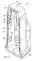
- FIG. 1illustrates a perspective view of a reduced pressure treatment system having a reduced pressure treatment unit and a multi-orientation, liquid-collection canister according to an illustrative embodiment
- FIG. 2illustrates an exploded perspective view of the reduced pressure treatment unit and liquid-collection canister of FIG. 1 ;
- FIG. 3illustrates an exploded perspective view of the liquid-collection canister of FIG. 1 ;
- FIG. 4illustrates a front perspective view of the liquid-collection canister of FIG. 3 with covers and filter elements associated with the liquid-collection canister being removed;
- FIG. 5illustrates a rear perspective view of the liquid-collection canister of FIG. 4 ;
- FIG. 6illustrates a front view of the liquid-collection canister of FIG. 4 ;
- FIG. 7illustrates a rear view of the liquid-collection canister of FIG. 4 ;
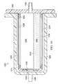
- FIG. 8illustrates a perspective cross-sectional view of the liquid-collection canister of FIG. 2 taken at 8 - 8 ;
- FIG. 9illustrates a cross-sectional view of the liquid-collection canister of FIG. 4 taken at 9 - 9 , the liquid-collection canister shown containing a liquid;
- FIG. 10illustrates a cross-sectional view of the liquid-collection canister of FIG. 9 rotated ninety degrees clockwise;
- FIG. 11illustrates a cross-sectional view of the liquid-collection canister similar to that of FIG. 8 , but rotated ninety degrees clockwise, the liquid-collection canister shown containing a liquid;
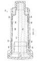
- FIG. 12illustrates an exploded perspective view of a reduced pressure treatment system having a multi-orientation, liquid-collection canister according to an illustrative embodiment, the liquid-collection canister having an outer shell and an inner liner;
- FIG. 13illustrates an assembled front view of the liquid-collection canister of FIG. 12 ;
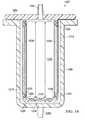
- FIG. 14illustrates a cross-sectional side view of the liquid-collection canister of FIG. 13 taken at 14 - 14 ;
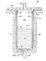
- FIG. 15illustrates a cross-sectional side view of the liquid-collection canister of FIG. 14 , the liquid-collection canister shown containing a liquid;
- FIG. 16illustrates a cross-sectional view of the liquid-collection canister of FIG. 15 rotated ninety degrees clockwise.
- reduced pressuregenerally refers to a pressure less than the ambient pressure at a tissue site that is being subjected to treatment. In most cases, this reduced pressure will be less than the atmospheric pressure at which the patient is located. Alternatively, the reduced pressure may be less than a hydrostatic pressure associated with tissue at the tissue site. Although the terms “vacuum” and “negative pressure” may be used to describe the pressure applied to the tissue site, the actual pressure reduction applied to the tissue site may be significantly less than the pressure reduction normally associated with a complete vacuum. Reduced pressure may initially generate fluid flow in the area of the tissue site. As the hydrostatic pressure around the tissue site approaches the desired reduced pressure, the flow may subside, and the reduced pressure is then maintained. Unless otherwise indicated, values of pressure stated herein are gauge pressures. Similarly, references to increases in reduced pressure typically refer to a decrease in absolute pressure, while decreases in reduced pressure typically refer to an increase in absolute pressure.
- tissue siterefers to a wound or defect located on or within any tissue, including but not limited to, bone tissue, adipose tissue, muscle tissue, neural tissue, dermal tissue, vascular tissue, connective tissue, cartilage, tendons, or ligaments.
- tissue sitemay further refer to areas of any tissue that are not necessarily wounded or defective, but are instead areas in which it is desired to add or promote the growth of additional tissue. For example, reduced pressure tissue treatment may be used in certain tissue areas to grow additional tissue that may be harvested and transplanted to another tissue location.
- a reduced pressure treatment system 100 for applying a reduced pressure to a tissue site 101 of a patientincludes a canister 102 in fluid communication with a reduced pressure source 108 and a reduced pressure dressing 112 that is positioned at the tissue site 101 .
- the reduced pressure dressing 112is fluidly connected to an inlet of the canister 102 by a conduit 120 .
- the conduit 120may fluidly communicate with the reduced pressure dressing 112 through a tubing adapter 124 .
- the canister used to collect exudate or other fluids from the tissue siteis configured to allow the canister to operate in multiple orientations even as the canister begins to fill with liquid.
- the canisterpreferably includes a protected gas communication pathway, or dry space, that allows continued fluid communication with a liquid collection chamber of the canister as exudate and other liquids collect within the liquid collection chamber.
- the path of fluid communication in the reduced pressure treatment systemis as follows. Reduced pressure is supplied to the gas communication pathway of the canister by the reduced pressure source. Typically this occurs by the reduced pressure source drawing gaseous fluids, such as air, from the gas communication pathway.
- liquid collection chamber of the canisterAs the pressure within the gas communication pathway falls, gas flows from the liquid collection chamber of the canister to the gas communication pathway, thus resulting in a drop in pressure within the liquid collection chamber. Liquid is prevented from flowing into the gas communication pathway by a hydrophobic element, an oleophobic element, or some other type of liquid-blocking membrane or device.
- the reduced pressure within the liquid collection chamberis transmitted to the dressing at the tissue site, which allows fluids (both gases and liquids) to flow from the tissue site to the liquid collection chamber.
- the liquidcollects within the liquid collection chamber.
- Multiple fluid communication ports between the liquid collection chamber and the gas communication pathwayallow continued gaseous communication between the liquid collection chamber and the gas communication pathway even as the liquid collection chamber fills with liquids and blocks some of these communication ports.
- a large common portmay be provided so that only a portion of the port is covered or blocked by liquid as the canister fills.
- the reduced pressure source 108is an electrically-driven vacuum pump.
- the reduced pressure source 108may instead be a manually-actuated or manually-charged pump that does not require electrical power.
- the reduced pressure source 108instead may be any other type of reduced pressure pump, or alternatively a wall suction port such as those available in hospitals and other medical facilities.
- the reduced pressure source 108may be housed within or used in conjunction with a reduced pressure treatment unit 140 , which may also contain sensors, processing units, alarm indicators, memory, databases, software, display units, and user interfaces 110 that further facilitate the application of reduced pressure treatment to the tissue site 101 .
- a sensor or switchmay be disposed at or near the reduced pressure source 108 to determine a source pressure generated by the reduced pressure source 108 .
- the sensormay communicate with a processing unit that monitors and controls the reduced pressure that is delivered by the reduced pressure source 108 .
- the reduced pressure dressing 112includes a distribution manifold 144 adapted to be positioned at the tissue site 101 , and a cover 148 , or drape, that is positioned over the distribution manifold 144 to maintain reduced pressure beneath the cover 148 at the tissue site 101 .
- the cover 148may extend beyond a perimeter of the tissue site 101 and may include an adhesive or bonding agent on the cover 148 to secure the cover to tissue adjacent the tissue site 101 .
- the adhesive disposed on cover 148may be used to seal between the tissue and the cover 148 to prevent leakage of reduced pressure from the tissue site 101 .
- a seal layersuch as, for example, a hydrogel or other material may be disposed between the cover 148 and the tissue to augment or substitute for the sealing properties of the adhesive.
- the distribution manifold 144 of the reduced pressure dressing 112is adapted to contact the tissue site 101 .
- the distribution manifold 144may be partially or fully in contact with the tissue site 101 being treated by the reduced pressure dressing 112 .
- the distribution manifold 144may partially or fully fill the wound.
- the distribution manifold 144may be any size, shape, or thickness depending on a variety of factors, such as the type of treatment being implemented or the nature and size of the tissue site 101 .
- the size and shape of the distribution manifold 144may be customized by a user to cover a particular portion of the tissue site 101 , or to fill or partially fill the tissue site 101 .
- the distribution manifold 144may have, for example, a square shape, or may be shaped as a circle, oval, polygon, an irregular shape, or any other shape.
- the distribution manifold 144is a foam material that distributes reduced pressure to the tissue site 101 when the distribution manifold 144 is in contact with or near the tissue site 101 .
- the foam materialmay be either hydrophobic or hydrophilic.
- the distribution manifold 144is an open-cell, reticulated polyurethane foam such as GranuFoam® dressing available from Kinetic Concepts, Inc. of San Antonio, Tex.
- the distribution manifold 144also functions to wick fluid away from the tissue site 101 , while continuing to provide reduced pressure to the tissue site 101 as a manifold.
- the wicking properties of the distribution manifold 144draw fluid away from the tissue site 101 by capillary flow or other wicking mechanisms.
- An example of a hydrophilic foamis a polyvinyl alcohol, open-cell foam such as V.A.C. WhiteFoam® dressing available from Kinetic Concepts, Inc. of San Antonio, Tex.
- Other hydrophilic foamsmay include those made from polyether.
- Other foams that may exhibit hydrophilic characteristicsinclude hydrophobic foams that have been treated or coated to provide hydrophilicity.
- the distribution manifold 144may further promote granulation at the tissue site 101 when a reduced pressure is applied through the reduced pressure dressing 112 .
- any or all of the surfaces of the distribution manifold 144may have an uneven, coarse, or jagged profile that causes microstrains and stresses at the tissue site 101 when reduced pressure is applied through the distribution manifold 144 . These microstrains and stresses have been shown to increase new tissue growth.
- the distribution manifold 144may be constructed from bioresorbable materials that do not have to be removed from a patient's body following use of the reduced pressure dressing 112 .
- Suitable bioresorbable materialsmay include, without limitation, a polymeric blend of polylactic acid (PLA) and polyglycolic acid (PGA).
- the polymeric blendmay also include without limitation polycarbonates, polyfumarates, and capralactones.
- the distribution manifold 144may further serve as a scaffold for new cell-growth, or a scaffold material may be used in conjunction with the distribution manifold 144 to promote cell-growth.
- a scaffoldis a substance or structure used to enhance or promote the growth of cells or formation of tissue, such as a three-dimensional porous structure that provides a template for cell growth.
- Illustrative examples of scaffold materialsinclude calcium phosphate, collagen, PLA/PGA, coral hydroxy apatites, carbonates, or processed allograft materials.
- the canister 102includes a plurality of walls 202 to form a liquid collection chamber 206 (see FIG. 8 ).
- Each of the plurality of walls 202includes an outer surface 210 and an inner surface 214 .
- a recess 218is formed in the outer surface 210 of a wall 220 of the plurality of walls 202 .
- the recess 218may be substantially L-shaped and include a first leg portion 226 and a second leg portion 230 , the first and second leg portions 226 , 230 intersecting at an apex region 234 .
- a plurality of apertures 238is positioned at an end of the first leg portion 226 opposite the apex region 234
- another plurality of apertures 242is positioned at an end of the second leg portion 230 opposite the apex region 234
- a plurality of apertures 246may also be positioned in the apex region 234 .
- Each of the plurality of apertures 238 , 242 , 246is illustrated as including four apertures, but it should be noted that any number of apertures, including a single aperture, could be provided.
- the recess 218is capable of being covered by a cover 252 to create a space 254 (see FIG. 8 ) between the cover 252 and the wall 220 of the canister 102 .
- the cover 252could be attached directly to the outer surface 210 of the wall 220
- a raised flange 256may be provided within the recess 218 on which the cover 252 may be positioned. By positioning the cover 252 within the recess 218 , the cover 252 is capable of being flush with the outer surface 210 . By providing the raised flange 256 on which the cover 252 may rest, the space 254 between the cover 252 and the wall 220 is maintained to provide a gas-communication pathway within the wall 220 .
- the cover 252 and the walls 202 of the canister 102may be made from a plastic, thermoplastic, thermoset, fiber-type material, ceramic, metal, or any other material that is capable of maintaining a desired shape under the influence of a reduced pressure and that is capable of being exposed to wound fluids or other liquids.
- the cover 252may be adhesively bonded, welded, or attached in any other suitable manner to the wall 220 .
- the means of attachmentwill provide a substantially gas impermeable seal between the cover 252 and the wall 220 such that reduced pressure may be delivered through the gas-communication pathway (i.e. the space 254 ) within the wall 220 without leakage between the cover 252 and wall 220 .
- the space 254is positioned within the wall 220 by providing the recess 218 and cover 252
- the space 254may be integrally formed within the wall 220 without the use of a cover 252 .
- the space 254could be integrally molded within the wall 220 during construction of the canister 102 .
- the spaces or gas-communication pathways described hereinare referred to as being formed or positioned “within” a wall, it is to be understood that the space or gas-communication pathway may be integrally formed within the wall during construction, formed after construction of the wall by any suitable manufacturing technique, or formed within a recess or other depression that is then bordered on one or more sides by a cover.
- the apertures 238 , 242 , 246 positioned within the recess 218allow fluid communication between the liquid collection chamber 206 and the space 254 .
- a liquid-air separator 260 , 264 , 268is positioned over each of the plurality of apertures 238 , 242 , 246 .
- the liquid-air separatorsare hydrophobic membranes or material that allow the transmission of gases but substantially prevent the transmission of liquids through the liquid-air separator.
- the liquid-air separatorsmay be a gas permeable material that is coated with a hydrophobic substance to make the material substantially impermeable to liquid.
- the liquid-air separatormay be a chemically bonded fluorocarbon monomer using a plasma process, thus increasing the hydrophobicity of the liquid-air separator.
- the liquid-air separatorsmay also be oleophobic or lipophobic, or coated with an oleophobic or lipophobic substance.
- the oleophobicity or lipophobicity of the liquid-air separatorcontributes to the ability of the liquid-air separator to wick or shed exudate and other wound fluids if the liquid-air separator is incidentally contacted by the liquid.
- liquid-air separatorsinclude, without limitation, expanded polytetrafluoroethylene (ePTFE), polytetrafluoroethylene (PTFE), foam, spun fiberglass, cotton gauze, polyester, glass fibers, polypropylene, microfibers, porous polymeric membranes, or any other materials or substances that are hydrophobic, oleophobic, or lipophobic in nature.
- ePTFEexpanded polytetrafluoroethylene
- PTFEpolytetrafluoroethylene
- PTFEpolytetrafluoroethylene
- foamspun fiberglass
- cotton gauzepolyester
- glass fiberspolypropylene
- microfiberspolypropylene
- porous polymeric membranesor any other materials or substances that are hydrophobic, oleophobic, or lipophobic in nature.
- a recess 518is formed in the outer surface 210 of a wall 520 of the plurality of walls 202 .
- the recess 518may be substantially rectangular in shape and include a first end 526 and a second end 530 .
- a plurality of apertures 538is positioned at the first end 526 of the recess 518
- a plurality of apertures 542is positioned at a second end 530 of the recess 518 .
- each of the plurality of apertures 538 , 542is illustrated as including four apertures. It should be noted, however, that any number of apertures, including a single aperture, could be provided.
- the recess 518may be covered by a cover 552 to create a space 554 (see FIG. 8 ) between the cover 552 and the wall 520 of the canister 102 . While the cover 552 could be attached directly to the outer surface 210 of the wall 520 , in one embodiment, a raised flange 556 may be provided within the recess 518 on which the cover 552 may be positioned. By positioning the cover 552 within the recess 518 , the cover 552 is capable of being flush with the outer surface 210 of the wall 520 . The raised flange 556 on which the cover 552 may rest, maintains the space 554 between the cover 552 and the wall 520 to provide a gas-communication pathway within the wall 520 .
- cover 552may be adhesively bonded, welded, or attached in any other suitable manner to the wall 520 .
- the means of attachmentwill provide a substantially gas impermeable seal between the cover 552 and the wall 520 such that reduced pressure may be delivered through the gas-communication pathway (i.e. the space 554 ) within the wall 520 without leakage between the cover 552 and wall 520 .
- the space 554is positioned within the wall 520 by providing the recess 518 and cover 552
- the space 554may be integrally formed in the wall 520 such as by molding or any other suitable manufacturing technique.
- the apertures 538 , 542 positioned within the recess 518allow fluid communication between the liquid collection chamber 206 and the space 554 .
- a liquid-air separator 560 , 564is positioned over each of the plurality of apertures 538 , 542 .
- the liquid-air separators 560 , 564may be similar in material and construction to liquid-air separators 260 , 264 , 268 .
- a wall 610 of the plurality of walls 202is positioned between and adjoins wall 220 and wall 520 .
- a cap 620is positioned above the outer surface 210 of the wall 610 to create a manifold chamber 624 (see FIG. 8 ) between the outer surface 210 of the wall 610 and the cap 620 .
- the capincludes at least one reduced pressure port 628 to allow fluid communication between the reduced pressure source 108 and the manifold chamber 624 . Additional ports may be provided in cap 620 to provide additional fluid communication with manifold chamber 624 .
- a second portmay be included to allow communication with a pressure sensor used to measure the amount of pressure associated with the canister 102 .
- the cap 620may be joined to the wall 610 using means similar to that used to join the covers 252 , 552 to the walls 220 , 520 .
- the canister 102further includes a passage 634 that allows fluid communication between the space 254 and the manifold chamber 624 .
- a passage 638is provided to permit fluid communication between the space 554 and the manifold chamber 624 .
- Each of the passages 634 , 638is integrally formed within the walls 202 without penetrating the liquid collection chamber 206 .
- the canister 102may further include one or more absorbent pads 652 positioned in the liquid collection chamber 206 to absorb liquid collected drawn into the liquid collection chamber 206 from the tissue site 101 .
- the absorbent pads 652preferably include cellulose and sodium polyacrylate contained within a non-woven polypropylene pouch.
- the absorbent pads 652could be made from any absorbent, adsorbent, or desiccant material or substance. By capturing liquid, the absorbent pads 652 prevent sloshing of the liquid in the chamber and premature wetting of the liquid-air separators.
- a lower lid 664is provided to enclose the absorbent pads 652 within the liquid collection chamber 206 . While the lower lid could be removably attached to walls 202 , in another embodiment, the lower lid is permanently affixed to the walls 202 in a manner similar to that used to attach covers 252 , 552 and cap 620 .
- the lower lid 664includes an inlet port 668 that permits attachment of conduit 120 .
- the canister 102may be removable from reduced pressure therapy unit 140 .
- the canister 102may include a pair of attachment tabs 720 having locking clips 724 that serve to removably secure the canister 102 to mating detents or hardware within the therapy unit 140 . Removal of the canister 102 is accomplished by simultaneously exerting inward forces upon the attachment tabs 720 and pulling the canister 102 away from the therapy unit 140 . Removal of the canister 102 allows the canister 102 to be replaced with a new canister when the canister 102 has become full of wound exudate or other liquid collected from the tissue site 101 .
- the shape and positioning of the walls 202 of the canister 102could vary depending on the shape and size of the therapy unit 140 . In some embodiments, it may be desired to use a stand-alone canister that is not secured to a therapy unit, but rather that is only fluidly connected to a therapy unit or reduced pressure source by a conduit or other pathway. While the walls 202 of the canister illustrated in FIGS. 2-8 are substantially planar and are arranged substantially perpendicular to adjacent walls, the walls could instead be non-planar and could in some embodiments be positioned at non-perpendicular angles relative to adjacent walls. In another embodiment, a lesser number of walls may be provided such as, for example, in a configuration that includes a cylindrically or spherically shaped wall.
- one or more spaces or gas-communication pathwaysmay be formed in the cylindrically or spherically shaped wall.
- One or more aperturesmay be provided to communicate with the one or more spaces in the cylindrical or spherical wall, and the one or more apertures may be covered by one or more liquid-air separators.
- the spaces 254 , 554 or gas-communication pathwaysare illustrated in walls 220 , 520 , and the walls 220 , 520 are opposite one another.
- the walls containing the gas-communication pathwaysmay be adjacent one another.
- the walls containing gas-communication pathwaysmay not be adjacent or opposite one another. While illustrated in FIGS. 2-8 with only one space 254 , 554 per wall 220 , 520 , multiple, independent spaces or gas-communication pathways could be included within a particular wall of the canister.
- Each of the spacesmay communicate with a common plenum, such as manifold chamber 624 , or the individual spaces may be separately ducted to a common conduit or directly to reduced pressure source 108 .
- the canister 102 illustrated in FIGS. 2-8includes two walls having spaces 254 , 554 .
- the number of walls having spaces or gas-communication pathwaysis not limited. Such pathways may be provided in only one wall or may be present in all walls of the canister.
- the number of apertures providing fluid communication between a gas-communication pathway and the liquid collection chamberis not strictly limited. In some embodiments, multiple apertures may be provided and spaced apart within the gas-communication pathway to permit more efficient collection and utilization of the liquid collection chamber as described in more detail below.
- wound exudate and other liquidsare drawn from the tissue site 101 by the reduced pressure source.
- the liquidstravel through conduit 120 and into the liquid collection chamber 206 through the inlet port 668 of the lower lid 664 .
- the liquid collection chamber 206 of the canister 102forms a first space where liquid from the tissue site 101 is collected.
- the spaces 254 , 554 , or gas-communication pathways,are dry spaces that are substantially protected from liquid by the liquid-air separators 260 , 264 , 268 , 560 , 564 .
- the spaces 254 , 554allow the passage of gas as reduced pressure is applied by the reduced pressure source 108 gases are drawn from the liquid collection chamber 206 and the tissue site 101 .
- the flow of gases through the liquid collection chamber 206 and the spaces 254 , 554is reduced, but liquid may continue to be drawn from the tissue site 101 and collected in the liquid collection chamber 206 .
- a liquid line 912represents an upper surface of liquid 914 that is collected within the liquid collection chamber 206 .
- the liquid 914is substantially prevented from passing through the liquid-air separators 260 , 264 , 268 to enter the space 254 within wall 220 .
- the surface of the liquid 914 represented by liquid line 912is substantially planar and forms a liquid plane 918 .
- any portion of the liquid-air separators 260 , 264 , 268 below the surface of the liquid 914will no longer allow transmission or flow of gas between the liquid collection chamber 206 and the space 254 .
- the reduced pressurewill no longer be delivered or transferred to the liquid collection chamber 206 through the portion of the liquid-air separators 260 , 264 , 268 that is covered in liquid 914 .
- only liquid-air separator 264is above the surface of the liquid 914 , therefore, gas transmission between the liquid collection chamber 206 and the space 254 occurs only through plurality of apertures 242 .
- the liquid-air separator 264will continue to permit gas flow and transmission of reduced pressure.
- FIG. 9Because a cross-sectional view is illustrated in FIG. 9 , the apertures 538 , 542 and liquid-air separators 560 , 564 associated with wall 520 are not depicted. However, given the orientation of the canister in FIG. 9 , only liquid-air separator 560 is above the surface of the liquid 914 . Consequently, liquid-air separator 560 continues to allow gas to travel through the apertures 538 between liquid collection chamber 206 and space 554 . Liquid-air separator 564 is below the surface of the liquid 914 and in this position no longer allows passage of gas through the apertures 542 .
- liquid-air separator 260is below the surface of the liquid 914 and thus is not capable of transmitting gas from the liquid collection chamber 206 to the space 254 .
- Liquid-air separators 264 , 268are both above the surface of the liquid 914 and continue to allow communication of gaseous flow between the liquid collection chamber 206 and the space 254 through apertures 242 , 246 .
- the orientation of the canister 102 in this figureresults in both of the liquid-air separators 560 , 564 associated with wall 520 being located above the surface of the liquid 914 . This orientation permits gaseous communication through these liquid-air separators 560 , 564 .
- FIG. 11another orientation of the canister is illustrated 102 similar to the cross-section shown in FIG. 8 but rotated ninety degrees clockwise.
- all of the liquid-separators 260 , 264 , 268 associated with wall 220are beneath the surface of the liquid 914 , thereby preventing gaseous flow between the liquid collection chamber 206 and the space 254 through apertures 238 , 242 , 246 .
- both of the liquid-air separators 560 , 564 associated with wall 520are above the surface of the liquid and are therefore capable of allowing gaseous flow through apertures 538 , 542 .
- the shape, size and relative positioning of the liquid-air separatorsallow the canister to continue to transmit reduced pressure even as the level of liquid 914 within the canister 102 rises to and beyond the volume of the liquid collection chamber 206 being half full of liquid.
- This multi-orientation capability of the canister 102is not available with many liquid-collection canisters, especially those canisters that include a single filter element or multiple filter elements that are all arranged in a co-planar arrangement.
- the success of the canister 102 at allowing large volumes of liquid to be collected in any orientation of the canister 102is due in part to the placement of gas communication pathways within or along multiple walls of the canister 102 and providing at least one liquid-air separator on each of those walls. While it is not necessary, or may not be desired for reasons of cost, to have a liquid-air separator on each wall of the canister, the presence of liquid air separators on opposing walls of the canister, such as in the configuration shown in FIGS. 3-9 , provides efficient collection of large volumes of liquid even when one of the liquid-air-separator-containing walls is oriented downward such as is illustrated in FIG. 11 .
- liquid-air separatorsBy providing multiple liquid-air separators on each wall that includes liquid-air separators, the ability to collect higher volumes of liquid is increased when one of the liquid-air-separator-containing walls is oriented in an upright position such as is shown in FIGS. 9 and 10 . It should be noted that as a substitute for multiple liquid-air separators on a particular wall, a large liquid-air separator may be provided that covers an aperture or apertures having greater surface area. This may not always be preferred, however, due to high costs associated with the materials sometimes used for liquid-air separators.
- a liquid collection canister 1202includes an outer shell 1206 and an inner liner 1210 positionable within the outer shell 1206 such that a gas-communication pathway 1214 is created between the inner liner 1210 and the outer shell 1206 .
- the inner liner 1210includes a plurality of walls 1220 that together define a liquid collection chamber 1224 .
- An aperture 1230is provided in at least one of the walls 1220 , and a liquid-air separator 1238 is positioned over each aperture 1230 to allow the transmission of gases but substantially prevent the transmission of liquids through the liquid-air separator.
- the liquid-air separators 1238are similar in function and construction to the liquid-air separators 260 , 264 , 268 , 560 , 564 described previously.
- Both the inner liner 1210 and the outer shell 1206may be rectangular-prism shaped, and both are preferably open on one end.
- a plurality of absorbent pads 1242may be positioned within the liquid collection chamber 1224 .
- the absorbent pads 1242are similar in function and construction to the absorbent pads 652 described previously.
- a lid 1250is provided to close the open ends of both the inner liner 1210 and the outer shell 1206 when the inner liner 1210 has been inserted within the outer shell 1206 .
- An inlet port 1254is provided on the lid 1250 to allow fluid connection to a conduit such as conduit 120 of FIG. 1 .
- the inlet port 1254provides fluid communication between the conduit and the liquid collection chamber 1224 .
- a plurality of outlet ports 1258(see FIGS.
- outlet ports 1258are provided on the canister 1202 to provide fluid communication with the gas-communication pathway 1214 .
- One of the outlet ports 1258may be fluidly connected to reduced pressure source such as reduced pressure source 108 described previously.
- Another of the outlet ports 1258may be fluidly connected to a pressure sensor for measuring the amount of reduced pressure in the canister 102 .
- the shape and positioning of the walls 1220 of the inner liner 1210could vary depending on the shape and size of both the outer shell 1206 .
- the walls 1220 of the canister illustrated in FIGS. 12-14are substantially planar and are arranged substantially perpendicular to adjacent walls, the walls could instead be non-planar and could in some embodiments be positioned at non-perpendicular angles relative to adjacent walls.
- a lesser number of wallsmay be provided such as, for example, in a configuration that includes a cylindrically or spherically shaped wall. In such a configuration, one or more spaces or gas-communication pathways may be formed in the cylindrically or spherically shaped wall.
- the gas-communication pathway 1214is positioned between each of the walls 1220 and the outer shell 1206 , and each of the walls 1220 includes at least one of the liquid-air separators 1238 .
- the gas-communication pathway 1214 for a particular wallmay be continuous with or in fluid communication with the gas-communication pathways 1214 from other walls. Alternatively, some or all of the gas-communication pathways 1214 may be independent from one another.
- a gas-communication pathway 1214may not be associated with every wall 1220 of the inner liner 1210 . In other embodiments, a gas-communication pathway 1214 is associated with each wall 1220 of the inner liner 1210 .
- the walls 1220 having gas-communication pathwaysmay be adjacent one another, or alternatively, opposite one another. In the case of an irregularly-shaped canister, the walls containing gas-communication pathways may not be adjacent or opposite one another. While illustrated in FIGS. 12-14 with only one gas-communication pathway 1214 per wall 1220 , multiple, independent spaces or gas-communication pathways could be associated with a particular wall 1220 of the inner liner 1210 . Each of the spaces or gas-communication pathways may communicate with a common plenum, such as manifold chamber 624 (see FIG. 8 ), or the individual gas-communication pathways may be separately ducted to a common conduit or directly to the reduced pressure source.
- the number of apertures providing fluid communication between a gas-communication pathway and the liquid collection chamberis not strictly limited. In some embodiments, multiple apertures may be provided and spaced apart within the gas-communication pathway to permit more efficient collection and utilization of the liquid collection chamber.
- the liquid collection canister 1202may be used with a reduced pressure treatment system such as reduced pressure treatment system 100 to collect wound exudate and other liquids drawn from a tissue site by a reduced pressure source.
- the liquidsmay travel through a conduit connected between the reduced pressure source and the canister 1202 and into the liquid collection chamber 1224 through the inlet port 1254 of the lid 1250 .
- the liquid collection chamber 1224 of the canister 1202forms a first space where liquid from the tissue site is collected.
- the gas-communication pathway or pathways 1214 formed between the inner line 1210 and outer shell 1206are dry spaces that are substantially protected from liquid by the liquid-air separators 1238 .
- the gas-communication pathway pathways 1214allow the passage of gas as reduced pressure is applied by the reduced pressure source and gases are drawn from the liquid collection chamber 1224 and the tissue site. As the pressure at the tissue site and within the liquid collection chamber 1224 approach the desired amount of reduced pressure required for reduced pressure treatment or therapy, the flow of gases through the liquid collection chamber 1224 and the gas-communication pathways 1214 is reduced, but liquid may continue to be drawn from the tissue site and collected in the liquid collection chamber 1224 .
- a liquid line 1512represents an upper surface of liquid 1514 that is collected within the liquid collection chamber 1224 .
- the liquid 1514is substantially prevented from passing through the liquid-air separators 1238 to enter the gas-communication pathway 1214 between inner liner 1210 and outer shell 1206 .
- the surface of the liquid 1514 represented by liquid line 1512is substantially planar and forms a liquid plane 1518 .
- any portion of the liquid-air separators 1238 below the surface of the liquid 1514will no longer allow transmission or flow of gas between the liquid collection chamber 1224 and the gas-communication pathway 1214 .
- the reduced pressurewill no longer be delivered or transferred to the liquid collection chamber 1224 through the portion of the liquid-air separators 1238 that is covered in liquid 1514 .
- FIG. 15only the portion of liquid-air separators 1238 above the surface of the liquid 1514 continue to allow gas transmission. As long as a portion of the liquid-air separators 1238 remains uncovered by liquid 1514 , that portion of the liquid-air separators 1238 will continue to permit gas flow and transmission of reduced pressure.
- FIG. 16another orientation of the canister 1202 is illustrated similar to the cross-section shown in FIG. 15 but rotated ninety degrees clockwise.
- the liquid-separator 1238 positioned beneath the surface of the liquid 1514no longer allows gaseous flow between the liquid collection chamber 1224 and the gas-communication pathway 1214 .
- the liquid-air separators (or portions thereof) positioned above the surface of the liquidare capable of allowing gaseous flow.
- a method of collecting liquid from a tissue sitemay include applying a reduced pressure to a first gas-communication pathway positioned within a first wall of a canister such as the liquid-collection canisters described with reference to FIGS. 1-16 .
- the reduced pressureis also applied to a second gas-communication pathway positioned within a second wall of the canister. Gaseous flow is allowed between a liquid collection chamber of the canister and the first and second gas-communication pathways to deliver the reduced pressure to the liquid collection chamber.
- the liquidis drawn into the liquid collection chamber and is substantially prevented from entering the first and second gas-communication pathways.
- a method of administering reduced pressure treatment to a tissue siteincludes applying a reduced pressure to a first gas-communication pathway positioned within a first wall of a canister and applying the reduced pressure to a second gas-communication pathway positioned within a second wall of the canister. Gaseous flow is allowed between a liquid collection chamber of the canister and the first and second gas-communication pathways to deliver the reduced pressure to the liquid collection chamber. The reduced pressure is communicated from the liquid collection chamber to the tissue site, and a liquid is drawn from the tissue site into the liquid collection chamber. The liquid is substantially prevented from entering the first and second gas-communication pathways.
Landscapes
- Health & Medical Sciences (AREA)
- Heart & Thoracic Surgery (AREA)
- Vascular Medicine (AREA)
- Engineering & Computer Science (AREA)
- Anesthesiology (AREA)
- Biomedical Technology (AREA)
- Hematology (AREA)
- Life Sciences & Earth Sciences (AREA)
- Animal Behavior & Ethology (AREA)
- General Health & Medical Sciences (AREA)
- Public Health (AREA)
- Veterinary Medicine (AREA)
- Media Introduction/Drainage Providing Device (AREA)
- External Artificial Organs (AREA)
- Cyclones (AREA)
Abstract
Description
Claims (6)
Priority Applications (21)
| Application Number | Priority Date | Filing Date | Title |
|---|---|---|---|
| US12/973,623US8377018B2 (en) | 2009-12-23 | 2010-12-20 | Reduced-pressure, multi-orientation, liquid-collection canister |
| CN201510881144.7ACN105435316B (en) | 2009-12-23 | 2010-12-21 | Reduced-pressure, multi-orientation, liquid-collection canister |
| PCT/US2010/061633WO2011079144A2 (en) | 2009-12-23 | 2010-12-21 | Reduced-pressure, multi-orientation, liquid-collection canister |
| ES15159193.0TES2649182T3 (en) | 2009-12-23 | 2010-12-21 | Liquid collection vessel with reduced pressure with multiorientation |
| CA3025743ACA3025743C (en) | 2009-12-23 | 2010-12-21 | Reduced-pressure, multi-orientation, liquid-collection canister |
| EP20179957.4AEP3735995B1 (en) | 2009-12-23 | 2010-12-21 | Reduced-pressure, multi-orientation, liquid-collection canister |
| CN201810799168.1ACN108837194B (en) | 2009-12-23 | 2010-12-21 | Pressure-reducing multi-directional liquid collecting tank |
| EP15159193.0AEP2926844B1 (en) | 2009-12-23 | 2010-12-21 | Reduced-pressure, multi-orientation, liquid-collection canister |
| CA2780823ACA2780823C (en) | 2009-12-23 | 2010-12-21 | Reduced-pressure, multi-orientation, liquid-collection canister |
| AU2010336535AAU2010336535B2 (en) | 2009-12-23 | 2010-12-21 | Reduced-pressure, multi-orientation, liquid-collection canister |
| EP17196749.0AEP3292879A1 (en) | 2009-12-23 | 2010-12-21 | Reduced-pressure, multi-orientation, liquid-collection canister |
| JP2012546163AJP5781539B2 (en) | 2009-12-23 | 2010-12-21 | Depressurized, multi-directional, liquid collection canister |
| EP10805350.5AEP2515962B1 (en) | 2009-12-23 | 2010-12-21 | Reduced-pressure, multi-orientation, liquid-collection canister |
| CN202110250349.0ACN113041413A (en) | 2009-12-23 | 2010-12-21 | Pressure-reducing multi-directional liquid collecting tank |
| CN201080057902.9ACN102933239B (en) | 2009-12-23 | 2010-12-21 | Decompression multi-directional liquid collection tank |
| TW099145624ATWI469805B (en) | 2009-12-23 | 2010-12-23 | Reduced-pressure, multi-orientation, liquid-collection canister |
| TW103141667ATW201509455A (en) | 2009-12-23 | 2010-12-23 | Reduced-pressure, multi-orientation, liquid-collection canister |
| US13/728,538US8801686B2 (en) | 2009-12-23 | 2012-12-27 | Reduced-pressure, multi-orientation, liquid-collection canister |
| US14/321,598US9814806B2 (en) | 2009-12-23 | 2014-07-01 | Reduced-pressure, multi-orientation, liquid-collection canister |
| US15/729,446US11173236B2 (en) | 2009-12-23 | 2017-10-10 | Reduced-pressure, multi-orientation, liquid-collection canister |
| US17/501,615US12138379B2 (en) | 2009-12-23 | 2021-10-14 | Reduced-pressure, multi-orientation, liquid-collection canister |
Applications Claiming Priority (2)
| Application Number | Priority Date | Filing Date | Title |
|---|---|---|---|
| US28993809P | 2009-12-23 | 2009-12-23 | |
| US12/973,623US8377018B2 (en) | 2009-12-23 | 2010-12-20 | Reduced-pressure, multi-orientation, liquid-collection canister |
Related Child Applications (1)
| Application Number | Title | Priority Date | Filing Date |
|---|---|---|---|
| US13/728,538ContinuationUS8801686B2 (en) | 2009-12-23 | 2012-12-27 | Reduced-pressure, multi-orientation, liquid-collection canister |
Publications (2)
| Publication Number | Publication Date |
|---|---|
| US20110152799A1 US20110152799A1 (en) | 2011-06-23 |
| US8377018B2true US8377018B2 (en) | 2013-02-19 |
Family
ID=44152100
Family Applications (5)
| Application Number | Title | Priority Date | Filing Date |
|---|---|---|---|
| US12/973,623Active2031-05-19US8377018B2 (en) | 2009-12-23 | 2010-12-20 | Reduced-pressure, multi-orientation, liquid-collection canister |
| US13/728,538ActiveUS8801686B2 (en) | 2009-12-23 | 2012-12-27 | Reduced-pressure, multi-orientation, liquid-collection canister |
| US14/321,598Active2033-01-18US9814806B2 (en) | 2009-12-23 | 2014-07-01 | Reduced-pressure, multi-orientation, liquid-collection canister |
| US15/729,446Active2033-07-12US11173236B2 (en) | 2009-12-23 | 2017-10-10 | Reduced-pressure, multi-orientation, liquid-collection canister |
| US17/501,615Active2031-12-20US12138379B2 (en) | 2009-12-23 | 2021-10-14 | Reduced-pressure, multi-orientation, liquid-collection canister |
Family Applications After (4)
| Application Number | Title | Priority Date | Filing Date |
|---|---|---|---|
| US13/728,538ActiveUS8801686B2 (en) | 2009-12-23 | 2012-12-27 | Reduced-pressure, multi-orientation, liquid-collection canister |
| US14/321,598Active2033-01-18US9814806B2 (en) | 2009-12-23 | 2014-07-01 | Reduced-pressure, multi-orientation, liquid-collection canister |
| US15/729,446Active2033-07-12US11173236B2 (en) | 2009-12-23 | 2017-10-10 | Reduced-pressure, multi-orientation, liquid-collection canister |
| US17/501,615Active2031-12-20US12138379B2 (en) | 2009-12-23 | 2021-10-14 | Reduced-pressure, multi-orientation, liquid-collection canister |
Country Status (9)
| Country | Link |
|---|---|
| US (5) | US8377018B2 (en) |
| EP (4) | EP3735995B1 (en) |
| JP (1) | JP5781539B2 (en) |
| CN (4) | CN108837194B (en) |
| AU (4) | AU2010336535B2 (en) |
| CA (2) | CA2780823C (en) |
| ES (1) | ES2649182T3 (en) |
| TW (2) | TW201509455A (en) |
| WO (1) | WO2011079144A2 (en) |
Cited By (12)
| Publication number | Priority date | Publication date | Assignee | Title |
|---|---|---|---|---|
| US20130116639A1 (en)* | 2009-12-23 | 2013-05-09 | Kci Licensing, Inc. | Reduced-pressure, multi-orientation, liquid-collection canister |
| US9526920B2 (en) | 2010-10-12 | 2016-12-27 | Smith & Nephew, Inc. | Medical device |
| US9737649B2 (en) | 2013-03-14 | 2017-08-22 | Smith & Nephew, Inc. | Systems and methods for applying reduced pressure therapy |
| US9770369B2 (en) | 2014-08-08 | 2017-09-26 | Neogenix, Llc | Wound care devices, apparatus, and treatment methods |
| US10155070B2 (en) | 2013-08-13 | 2018-12-18 | Smith & Nephew, Inc. | Systems and methods for applying reduced pressure therapy |
| US10328188B2 (en) | 2013-03-14 | 2019-06-25 | Smith & Nephew, Inc. | Systems and methods for applying reduced pressure therapy |
| US10744239B2 (en) | 2014-07-31 | 2020-08-18 | Smith & Nephew, Inc. | Leak detection in negative pressure wound therapy system |
| USD895787S1 (en)* | 2019-05-10 | 2020-09-08 | Kci Licensing, Inc. | Negative pressure therapy device |
| US20210113745A1 (en)* | 2012-02-21 | 2021-04-22 | Kci Licensing, Inc. | Multi-Orientation Canister For Use With A Reduced Pressure Treatment System |
| USD977624S1 (en) | 2016-02-29 | 2023-02-07 | Smith & Nephew Plc | Portable negative pressure apparatus |
| US12133789B2 (en) | 2014-07-31 | 2024-11-05 | Smith & Nephew, Inc. | Reduced pressure therapy apparatus construction and control |
| US12280203B2 (en) | 2019-10-03 | 2025-04-22 | T.J.Smith And Nephew, Limited | Apparatuses and methods for negative pressure wound therapy |
Families Citing this family (26)
| Publication number | Priority date | Publication date | Assignee | Title |
|---|---|---|---|---|
| US8795257B2 (en) | 2010-07-19 | 2014-08-05 | Kci Licensing, Inc. | Systems and methods for electrically detecting the presence of exudate in dressings |
| USD675728S1 (en)* | 2010-07-20 | 2013-02-05 | Kci Licensing, Inc. | Fluid-collection canister for reduced pressure treatment |
| US20120109034A1 (en)* | 2010-10-27 | 2012-05-03 | Kci Licensing, Inc. | Interactive, wireless reduced-pressure dressings, methods, and systems |
| CN103796692B (en)* | 2011-09-13 | 2016-06-22 | 凯希特许有限公司 | Pressure Relief Tanks with Hydrophobic Pores |
| WO2013059277A1 (en)* | 2011-10-17 | 2013-04-25 | Kci Licensing, Inc. | System and apparatus for treating a tissue site having an in-line canister |
| EP3081240B1 (en)* | 2012-02-21 | 2019-04-03 | KCI Licensing, Inc. | A multi-orientation canister for use with a reduced pressure treatment system |
| WO2013173705A1 (en) | 2012-05-18 | 2013-11-21 | Basf Se | Encapsulated particle |
| KR20150013788A (en) | 2012-05-18 | 2015-02-05 | 바스프 에스이 | An encapsulated particle |
| US9944568B2 (en) | 2012-11-16 | 2018-04-17 | Basf Se | Encapsulated fertilizer particle containing pesticide |
| USD764654S1 (en) | 2014-03-13 | 2016-08-23 | Smith & Nephew, Inc. | Canister for collecting wound exudate |
| WO2014150539A2 (en)* | 2013-03-18 | 2014-09-25 | Kci Licensing, Inc. | System and method for multiple direction flexible inline canister |
| EP4092764A1 (en) | 2013-04-03 | 2022-11-23 | Lg Electronics Inc. | Solar cell |
| USD764048S1 (en) | 2014-05-28 | 2016-08-16 | Smith & Nephew, Inc. | Device for applying negative pressure to a wound |
| USD764653S1 (en) | 2014-05-28 | 2016-08-23 | Smith & Nephew, Inc. | Canister for collecting wound exudate |
| USD764047S1 (en) | 2014-05-28 | 2016-08-16 | Smith & Nephew, Inc. | Therapy unit assembly |
| USD765830S1 (en) | 2014-06-02 | 2016-09-06 | Smith & Nephew, Inc. | Therapy unit assembly |
| USD770173S1 (en) | 2014-06-02 | 2016-11-01 | Smith & Nephew, Inc. | Bag |
| GB2543544A (en) | 2015-10-21 | 2017-04-26 | Brightwake Ltd | Wound dressing |
| GB201608099D0 (en) | 2016-05-09 | 2016-06-22 | Convatec Technologies Inc | Negative pressure wound dressing |
| DK3481349T3 (en) | 2016-07-08 | 2021-07-12 | Convatec Technologies Inc | Flexible vacuum system |
| MX2019000232A (en) | 2016-07-08 | 2019-11-12 | Convatec Technologies Inc | Fluid flow sensing. |
| EP3481348A4 (en) | 2016-07-08 | 2020-02-26 | ConvaTec Technologies Inc. | Fluid collection apparatus |
| WO2018195101A1 (en)* | 2017-04-19 | 2018-10-25 | Smith & Nephew, Inc. | Negative pressure wound therapy canisters |
| US11826234B2 (en)* | 2018-06-28 | 2023-11-28 | Kci Licensing, Inc. | Distributed negative pressure wound therapy system incorporating an absorbent dressing and piezo-electric pump |
| EP3666301B1 (en)* | 2018-12-14 | 2024-02-21 | Mölnlycke Health Care AB | A canister for a mobile negative pressure wound therapy device |
| CN119950827A (en)* | 2024-12-26 | 2025-05-09 | 萨科(厦门)医疗科技有限公司 | A negative pressure drainage bottle |
Citations (123)
| Publication number | Priority date | Publication date | Assignee | Title |
|---|---|---|---|---|
| US1355846A (en) | 1920-02-06 | 1920-10-19 | David A Rannells | Medical appliance |
| US2547758A (en) | 1949-01-05 | 1951-04-03 | Wilmer B Keeling | Instrument for treating the male urethra |
| US2632443A (en) | 1949-04-18 | 1953-03-24 | Eleanor P Lesher | Surgical dressing |
| GB692578A (en) | 1949-09-13 | 1953-06-10 | Minnesota Mining & Mfg | Improvements in or relating to drape sheets for surgical use |
| US2682873A (en) | 1952-07-30 | 1954-07-06 | Johnson & Johnson | General purpose protective dressing |
| US2910763A (en) | 1955-08-17 | 1959-11-03 | Du Pont | Felt-like products |
| US2969057A (en) | 1957-11-04 | 1961-01-24 | Brady Co W H | Nematodic swab |
| US3066672A (en) | 1960-09-27 | 1962-12-04 | Jr William H Crosby | Method and apparatus for serial sampling of intestinal juice |
| US3367332A (en) | 1965-08-27 | 1968-02-06 | Gen Electric | Product and process for establishing a sterile area of skin |
| US3520300A (en) | 1967-03-15 | 1970-07-14 | Amp Inc | Surgical sponge and suction device |
| US3568675A (en) | 1968-08-30 | 1971-03-09 | Clyde B Harvey | Fistula and penetrating wound dressing |
| US3648692A (en) | 1970-12-07 | 1972-03-14 | Parke Davis & Co | Medical-surgical dressing for burns and the like |
| US3682180A (en) | 1970-06-08 | 1972-08-08 | Coilform Co Inc | Drain clip for surgical drain |
| US3719197A (en) | 1971-03-04 | 1973-03-06 | Voys Inc Le | Aseptic suction drainage system and valve therefor |
| US3826254A (en) | 1973-02-26 | 1974-07-30 | Verco Ind | Needle or catheter retaining appliance |
| DE2640413A1 (en) | 1976-09-08 | 1978-03-09 | Wolf Gmbh Richard | CATHETER MONITORING DEVICE |
| US4080970A (en) | 1976-11-17 | 1978-03-28 | Miller Thomas J | Post-operative combination dressing and internal drain tube with external shield and tube connector |
| US4096853A (en) | 1975-06-21 | 1978-06-27 | Hoechst Aktiengesellschaft | Device for the introduction of contrast medium into an anus praeter |
| US4139004A (en) | 1977-02-17 | 1979-02-13 | Gonzalez Jr Harry | Bandage apparatus for treating burns |
| US4165748A (en) | 1977-11-07 | 1979-08-28 | Johnson Melissa C | Catheter tube holder |
| US4184510A (en) | 1977-03-15 | 1980-01-22 | Fibra-Sonics, Inc. | Valued device for controlling vacuum in surgery |
| US4233969A (en) | 1976-11-11 | 1980-11-18 | Lock Peter M | Wound dressing materials |
| US4245630A (en) | 1976-10-08 | 1981-01-20 | T. J. Smith & Nephew, Ltd. | Tearable composite strip of materials |
| US4256109A (en) | 1978-07-10 | 1981-03-17 | Nichols Robert L | Shut off valve for medical suction apparatus |
| US4261363A (en) | 1979-11-09 | 1981-04-14 | C. R. Bard, Inc. | Retention clips for body fluid drains |
| US4275721A (en) | 1978-11-28 | 1981-06-30 | Landstingens Inkopscentral Lic, Ekonomisk Forening | Vein catheter bandage |
| US4284079A (en) | 1979-06-28 | 1981-08-18 | Adair Edwin Lloyd | Method for applying a male incontinence device |
| US4297995A (en) | 1980-06-03 | 1981-11-03 | Key Pharmaceuticals, Inc. | Bandage containing attachment post |
| US4333468A (en) | 1980-08-18 | 1982-06-08 | Geist Robert W | Mesentery tube holder apparatus |
| US4373519A (en) | 1981-06-26 | 1983-02-15 | Minnesota Mining And Manufacturing Company | Composite wound dressing |
| US4382441A (en) | 1978-12-06 | 1983-05-10 | Svedman Paul | Device for treating tissues, for example skin |
| US4392858A (en) | 1981-07-16 | 1983-07-12 | Sherwood Medical Company | Wound drainage device |
| US4392853A (en) | 1981-03-16 | 1983-07-12 | Rudolph Muto | Sterile assembly for protecting and fastening an indwelling device |
| US4419097A (en) | 1981-07-31 | 1983-12-06 | Rexar Industries, Inc. | Attachment for catheter tube |
| EP0100148A1 (en) | 1982-07-06 | 1984-02-08 | Dow Corning Limited | Medical-surgical dressing and a process for the production thereof |
| US4465485A (en) | 1981-03-06 | 1984-08-14 | Becton, Dickinson And Company | Suction canister with unitary shut-off valve and filter features |
| EP0117632A2 (en) | 1983-01-27 | 1984-09-05 | Johnson & Johnson Products Inc. | Adhesive film dressing |
| US4475909A (en) | 1982-05-06 | 1984-10-09 | Eisenberg Melvin I | Male urinary device and method for applying the device |
| US4480638A (en) | 1980-03-11 | 1984-11-06 | Eduard Schmid | Cushion for holding an element of grafted skin |
| US4525166A (en) | 1981-11-21 | 1985-06-25 | Intermedicat Gmbh | Rolled flexible medical suction drainage device |
| US4525374A (en) | 1984-02-27 | 1985-06-25 | Manresa, Inc. | Treating hydrophobic filters to render them hydrophilic |
| US4540412A (en) | 1983-07-14 | 1985-09-10 | The Kendall Company | Device for moist heat therapy |
| US4543100A (en) | 1983-11-01 | 1985-09-24 | Brodsky Stuart A | Catheter and drain tube retainer |
| US4548202A (en) | 1983-06-20 | 1985-10-22 | Ethicon, Inc. | Mesh tissue fasteners |
| US4551139A (en) | 1982-02-08 | 1985-11-05 | Marion Laboratories, Inc. | Method and apparatus for burn wound treatment |
| EP0161865A2 (en) | 1984-05-03 | 1985-11-21 | Smith and Nephew Associated Companies p.l.c. | Adhesive wound dressing |
| US4569348A (en) | 1980-02-22 | 1986-02-11 | Velcro Usa Inc. | Catheter tube holder strap |
| US4605399A (en) | 1984-12-04 | 1986-08-12 | Complex, Inc. | Transdermal infusion device |
| US4608041A (en) | 1981-10-14 | 1986-08-26 | Frese Nielsen | Device for treatment of wounds in body tissue of patients by exposure to jets of gas |
| US4640688A (en) | 1985-08-23 | 1987-02-03 | Mentor Corporation | Urine collection catheter |
| US4655754A (en) | 1984-11-09 | 1987-04-07 | Stryker Corporation | Vacuum wound drainage system and lipids baffle therefor |
| US4664662A (en) | 1984-08-02 | 1987-05-12 | Smith And Nephew Associated Companies Plc | Wound dressing |
| US4710165A (en) | 1985-09-16 | 1987-12-01 | Mcneil Charles B | Wearable, variable rate suction/collection device |
| US4733659A (en) | 1986-01-17 | 1988-03-29 | Seton Company | Foam bandage |
| GB2195255A (en) | 1986-09-30 | 1988-04-07 | Vacutec Uk Limited | Method and apparatus for vacuum treatment of an epidermal surface |
| US4743232A (en) | 1986-10-06 | 1988-05-10 | The Clinipad Corporation | Package assembly for plastic film bandage |
| GB2197789A (en) | 1986-11-28 | 1988-06-02 | Smiths Industries Plc | Anti-foaming disinfectants used in surgical suction apparatus |
| US4758220A (en) | 1985-09-26 | 1988-07-19 | Alcon Laboratories, Inc. | Surgical cassette proximity sensing and latching apparatus |
| US4787888A (en) | 1987-06-01 | 1988-11-29 | University Of Connecticut | Disposable piezoelectric polymer bandage for percutaneous delivery of drugs and method for such percutaneous delivery (a) |
| US4826494A (en) | 1984-11-09 | 1989-05-02 | Stryker Corporation | Vacuum wound drainage system |
| US4838883A (en) | 1986-03-07 | 1989-06-13 | Nissho Corporation | Urine-collecting device |
| US4840187A (en) | 1986-09-11 | 1989-06-20 | Bard Limited | Sheath applicator |
| US4863449A (en) | 1987-07-06 | 1989-09-05 | Hollister Incorporated | Adhesive-lined elastic condom cathether |
| US4872450A (en) | 1984-08-17 | 1989-10-10 | Austad Eric D | Wound dressing and method of forming same |
| US4878901A (en) | 1986-10-10 | 1989-11-07 | Sachse Hans Ernst | Condom catheter, a urethral catheter for the prevention of ascending infections |
| GB2220357A (en) | 1988-05-28 | 1990-01-10 | Smiths Industries Plc | Medico-surgical containers |
| US4897081A (en) | 1984-05-25 | 1990-01-30 | Thermedics Inc. | Percutaneous access device |
| US4906233A (en) | 1986-05-29 | 1990-03-06 | Terumo Kabushiki Kaisha | Method of securing a catheter body to a human skin surface |
| US4906240A (en) | 1988-02-01 | 1990-03-06 | Matrix Medica, Inc. | Adhesive-faced porous absorbent sheet and method of making same |
| US4919654A (en) | 1988-08-03 | 1990-04-24 | Kalt Medical Corporation | IV clamp with membrane |
| CA2005436A1 (en) | 1988-12-13 | 1990-06-13 | Glenda G. Kalt | Transparent tracheostomy tube dressing |
| US4941882A (en) | 1987-03-14 | 1990-07-17 | Smith And Nephew Associated Companies, P.L.C. | Adhesive dressing for retaining a cannula on the skin |
| US4953565A (en) | 1986-11-26 | 1990-09-04 | Shunro Tachibana | Endermic application kits for external medicines |
| US4969880A (en) | 1989-04-03 | 1990-11-13 | Zamierowski David S | Wound dressing and treatment method |
| US4985019A (en) | 1988-03-11 | 1991-01-15 | Michelson Gary K | X-ray marker |
| GB2235877A (en) | 1989-09-18 | 1991-03-20 | Antonio Talluri | Closed wound suction apparatus |
| US5037397A (en) | 1985-05-03 | 1991-08-06 | Medical Distributors, Inc. | Universal clamp |
| US5086170A (en) | 1989-01-16 | 1992-02-04 | Roussel Uclaf | Process for the preparation of azabicyclo compounds |
| US5092858A (en) | 1990-03-20 | 1992-03-03 | Becton, Dickinson And Company | Liquid gelling agent distributor device |
| US5100396A (en) | 1989-04-03 | 1992-03-31 | Zamierowski David S | Fluidic connection system and method |
| US5134994A (en) | 1990-02-12 | 1992-08-04 | Say Sam L | Field aspirator in a soft pack with externally mounted container |
| US5149331A (en) | 1991-05-03 | 1992-09-22 | Ariel Ferdman | Method and device for wound closure |
| US5156602A (en) | 1990-09-05 | 1992-10-20 | Stryker Corporation | Hydrophobic filter protector for wound drainage system |
| US5167613A (en) | 1992-03-23 | 1992-12-01 | The Kendall Company | Composite vented wound dressing |
| US5176663A (en) | 1987-12-02 | 1993-01-05 | Pal Svedman | Dressing having pad with compressibility limiting elements |
| US5215522A (en) | 1984-07-23 | 1993-06-01 | Ballard Medical Products | Single use medical aspirating device and method |
| US5232453A (en) | 1989-07-14 | 1993-08-03 | E. R. Squibb & Sons, Inc. | Catheter holder |
| US5261893A (en) | 1989-04-03 | 1993-11-16 | Zamierowski David S | Fastening system and method |
| US5278100A (en) | 1991-11-08 | 1994-01-11 | Micron Technology, Inc. | Chemical vapor deposition technique for depositing titanium silicide on semiconductor wafers |
| US5279550A (en) | 1991-12-19 | 1994-01-18 | Gish Biomedical, Inc. | Orthopedic autotransfusion system |
| US5298015A (en) | 1989-07-11 | 1994-03-29 | Nippon Zeon Co., Ltd. | Wound dressing having a porous structure |
| WO1994014045A1 (en) | 1992-12-15 | 1994-06-23 | Langdon Medical, Inc. | An apparatus for collecting a fluid sample from a patient and container for storing the same |
| US5342376A (en) | 1993-05-03 | 1994-08-30 | Dermagraphics, Inc. | Inserting device for a barbed tissue connector |
| US5344415A (en) | 1993-06-15 | 1994-09-06 | Deroyal Industries, Inc. | Sterile system for dressing vascular access site |
| DE4306478A1 (en) | 1993-03-02 | 1994-09-08 | Wolfgang Dr Wagner | Drainage device, in particular pleural drainage device, and drainage method |
| US5358494A (en) | 1989-07-11 | 1994-10-25 | Svedman Paul | Irrigation dressing |
| US5437622A (en) | 1992-04-29 | 1995-08-01 | Laboratoire Hydrex (Sa) | Transparent adhesive dressing with reinforced starter cuts |
| US5437651A (en) | 1993-09-01 | 1995-08-01 | Research Medical, Inc. | Medical suction apparatus |
| DE29504378U1 (en) | 1995-03-15 | 1995-09-14 | MTG Medizinisch, technische Gerätebau GmbH, 66299 Friedrichsthal | Electronically controlled low-vacuum pump for chest and wound drainage |
| US5527293A (en) | 1989-04-03 | 1996-06-18 | Kinetic Concepts, Inc. | Fastening system and method |
| US5549584A (en) | 1994-02-14 | 1996-08-27 | The Kendall Company | Apparatus for removing fluid from a wound |
| US5556375A (en) | 1994-06-16 | 1996-09-17 | Hercules Incorporated | Wound dressing having a fenestrated base layer |
| US5607388A (en) | 1994-06-16 | 1997-03-04 | Hercules Incorporated | Multi-purpose wound dressing |
| US5636643A (en) | 1991-11-14 | 1997-06-10 | Wake Forest University | Wound treatment employing reduced pressure |
| US5645081A (en) | 1991-11-14 | 1997-07-08 | Wake Forest University | Method of treating tissue damage and apparatus for same |
| GB2333965A (en) | 1997-09-12 | 1999-08-11 | Kci Medical Ltd | Surgical drape |
| US6071267A (en) | 1998-02-06 | 2000-06-06 | Kinetic Concepts, Inc. | Medical patient fluid management interface system and method |
| US6135116A (en) | 1997-07-28 | 2000-10-24 | Kci Licensing, Inc. | Therapeutic method for treating ulcers |
| WO2001024846A1 (en) | 1999-10-01 | 2001-04-12 | Serres Oy | Suction bag assembly |
| US6241747B1 (en) | 1993-05-03 | 2001-06-05 | Quill Medical, Inc. | Barbed Bodily tissue connector |
| WO2001049344A1 (en) | 1999-12-31 | 2001-07-12 | Oy Nikomed Finland Ab | Suction bag device |
| US6287316B1 (en) | 1999-03-26 | 2001-09-11 | Ethicon, Inc. | Knitted surgical mesh |
| US20020077661A1 (en) | 2000-12-20 | 2002-06-20 | Vahid Saadat | Multi-barbed device for retaining tissue in apposition and methods of use |
| US20020115951A1 (en) | 2001-02-22 | 2002-08-22 | Core Products International, Inc. | Ankle brace providing upper and lower ankle adjustment |
| US20020120185A1 (en) | 2000-05-26 | 2002-08-29 | Kci Licensing, Inc. | System for combined transcutaneous blood gas monitoring and vacuum assisted wound closure |
| US20020143286A1 (en) | 2001-03-05 | 2002-10-03 | Kci Licensing, Inc. | Vacuum assisted wound treatment apparatus and infection identification system and method |
| US6488643B1 (en) | 1998-10-08 | 2002-12-03 | Kci Licensing, Inc. | Wound healing foot wrap |
| US6493568B1 (en) | 1994-07-19 | 2002-12-10 | Kci Licensing, Inc. | Patient interface system |
| AU755496B2 (en) | 1997-09-12 | 2002-12-12 | Kci Licensing, Inc. | Surgical drape and suction head for wound treatment |
| WO2007133618A2 (en) | 2006-05-11 | 2007-11-22 | Iasis Medical, Llc | Device and method for wound therapy |
| EP1905465A1 (en) | 2006-09-28 | 2008-04-02 | Tyco Healthcare Group LP | Portable wound therapy system |
| US20090292263A1 (en) | 2008-05-21 | 2009-11-26 | Tyco Healthcare Group, Lp | Wound therapy system with portable container apparatus |
| US20100063463A1 (en) | 2008-09-05 | 2010-03-11 | Tyco Healthcare Group Lp | Canister membrane for wound therapy system |
Family Cites Families (41)
| Publication number | Priority date | Publication date | Assignee | Title |
|---|---|---|---|---|
| US4266545A (en) | 1979-04-06 | 1981-05-12 | Moss James P | Portable suction device for collecting fluids from a closed wound |
| US4346711A (en)* | 1981-01-16 | 1982-08-31 | Sherwood Medical Industries Inc. | Body fluid collection device with disposable liner |
| US4681571A (en)* | 1981-04-23 | 1987-07-21 | C. R. Bard, Inc. | Suction canister with disposable liner and check valve |
| AU550575B2 (en) | 1981-08-07 | 1986-03-27 | Richard Christian Wright | Wound drainage device |
| EP0256060A1 (en) | 1986-01-31 | 1988-02-24 | OSMOND, Roger L. W. | Suction system for wound and gastro-intestinal drainage |
| EP0268848B1 (en)* | 1986-10-27 | 1992-05-20 | Mitsubishi Gas Chemical Company, Inc. | An oxygen absorbent package |
| GB8906100D0 (en) | 1989-03-16 | 1989-04-26 | Smith & Nephew | Laminates |
| JP2941918B2 (en) | 1990-09-19 | 1999-08-30 | テルモ株式会社 | Weighing device |
| SE500395C2 (en)* | 1992-10-16 | 1994-06-20 | Humanteknik Ab | Moisture absorbing device |
| DE9404048U1 (en)* | 1994-03-10 | 1994-08-18 | Infus Medical International-Vertrieb GmbH, 85560 Ebersberg | Device for the vacuum wound closure and / or for suctioning secretions or the like. |
| DE69505545T2 (en) | 1994-08-22 | 1999-03-11 | Kinetic Concepts Inc | WOUND DRAINAGE DEVICE |
| GB9523253D0 (en)* | 1995-11-14 | 1996-01-17 | Mediscus Prod Ltd | Portable wound treatment apparatus |
| ES2220734T3 (en) | 2000-02-24 | 2004-12-16 | Venetec International, Inc. | UNIVERSAL FIXING SYSTEM FOR CATETER. |
| US6648862B2 (en) | 2001-11-20 | 2003-11-18 | Spheric Products, Ltd. | Personally portable vacuum desiccator |
| US7846141B2 (en) | 2002-09-03 | 2010-12-07 | Bluesky Medical Group Incorporated | Reduced pressure treatment system |
| GB0224986D0 (en) | 2002-10-28 | 2002-12-04 | Smith & Nephew | Apparatus |
| US7976519B2 (en) | 2002-12-31 | 2011-07-12 | Kci Licensing, Inc. | Externally-applied patient interface system and method |
| JP4638347B2 (en)* | 2003-06-10 | 2011-02-23 | 大研医器株式会社 | Container and medical suction tool provided with the same |
| CN100591374C (en)* | 2003-09-09 | 2010-02-24 | 西弗科医疗器械公司 | Device for flushing, discharging and collecting tissues |
| US20050065484A1 (en) | 2003-09-10 | 2005-03-24 | Watson Richard L. | Wound healing apparatus with bioabsorbable material and suction tubes |
| GB0325126D0 (en) | 2003-10-28 | 2003-12-03 | Smith & Nephew | Apparatus with heat |
| GB0325120D0 (en) | 2003-10-28 | 2003-12-03 | Smith & Nephew | Apparatus with actives |
| US7790945B1 (en) | 2004-04-05 | 2010-09-07 | Kci Licensing, Inc. | Wound dressing with absorption and suction capabilities |
| US7909805B2 (en) | 2004-04-05 | 2011-03-22 | Bluesky Medical Group Incorporated | Flexible reduced pressure treatment appliance |
| US8529548B2 (en) | 2004-04-27 | 2013-09-10 | Smith & Nephew Plc | Wound treatment apparatus and method |
| US7824384B2 (en) | 2004-08-10 | 2010-11-02 | Kci Licensing, Inc. | Chest tube drainage system |
| US7419873B2 (en) | 2004-11-24 | 2008-09-02 | Cardiac Pacemakers, Inc. | Method and apparatus for providing flexible partially etched capacitor electrode interconnect |
| USD547438S1 (en) | 2004-12-04 | 2007-07-24 | Kci Licensing, Inc. | Portable negative pressure wound care appliance |
| CN101227936A (en)* | 2005-07-24 | 2008-07-23 | 卡尔梅利·阿达汗 | Wound Cover and Drainage System |
| DE202006001410U1 (en)* | 2006-01-30 | 2006-03-23 | Malamutmann, Viktor | suction device |
| US8079991B2 (en) | 2006-06-02 | 2011-12-20 | Kci Licensing Inc. | Wound suction peg apparatus |
| CN101454043B (en) | 2006-06-02 | 2012-07-11 | 凯希特许有限公司 | wound suction device |
| WO2008100446A2 (en)* | 2007-02-09 | 2008-08-21 | Kci Licensing Inc. | Apparatus and method for administering reduced pressure treatment to a tissue site |
| KR100888823B1 (en) | 2007-06-27 | 2009-03-17 | 삼성전자주식회사 | Nonvolatile Memory System, and Program Method of Nonvolatile Memory System |
| EP2471562B1 (en) | 2008-02-29 | 2013-11-27 | KCI Licensing, Inc. | A system for collecting exudates |
| US8021347B2 (en) | 2008-07-21 | 2011-09-20 | Tyco Healthcare Group Lp | Thin film wound dressing |
| US8007481B2 (en) | 2008-07-17 | 2011-08-30 | Tyco Healthcare Group Lp | Subatmospheric pressure mechanism for wound therapy system |
| CA2984749C (en)* | 2008-06-04 | 2020-06-23 | Kci Licensing, Inc. | Reduced-pressure, liquid-collection canister with multi-orientation filter |
| US8251979B2 (en)* | 2009-05-11 | 2012-08-28 | Tyco Healthcare Group Lp | Orientation independent canister for a negative pressure wound therapy device |
| US8216198B2 (en) | 2009-01-09 | 2012-07-10 | Tyco Healthcare Group Lp | Canister for receiving wound exudate in a negative pressure therapy system |
| US8377018B2 (en)* | 2009-12-23 | 2013-02-19 | Kci Licensing, Inc. | Reduced-pressure, multi-orientation, liquid-collection canister |
- 2010
- 2010-12-20USUS12/973,623patent/US8377018B2/enactiveActive
- 2010-12-21CNCN201810799168.1Apatent/CN108837194B/enactiveActive
- 2010-12-21CNCN201510881144.7Apatent/CN105435316B/enactiveActive
- 2010-12-21EPEP20179957.4Apatent/EP3735995B1/enactiveActive
- 2010-12-21CACA2780823Apatent/CA2780823C/enactiveActive
- 2010-12-21CNCN202110250349.0Apatent/CN113041413A/enactivePending
- 2010-12-21ESES15159193.0Tpatent/ES2649182T3/enactiveActive
- 2010-12-21CACA3025743Apatent/CA3025743C/enactiveActive
- 2010-12-21EPEP17196749.0Apatent/EP3292879A1/ennot_activeWithdrawn
- 2010-12-21AUAU2010336535Apatent/AU2010336535B2/enactiveActive
- 2010-12-21CNCN201080057902.9Apatent/CN102933239B/enactiveActive
- 2010-12-21EPEP10805350.5Apatent/EP2515962B1/enactiveActive
- 2010-12-21WOPCT/US2010/061633patent/WO2011079144A2/enactiveApplication Filing
- 2010-12-21EPEP15159193.0Apatent/EP2926844B1/enactiveActive
- 2010-12-21JPJP2012546163Apatent/JP5781539B2/enactiveActive
- 2010-12-23TWTW103141667Apatent/TW201509455A/enunknown
- 2010-12-23TWTW099145624Apatent/TWI469805B/ennot_activeIP Right Cessation
- 2012
- 2012-12-27USUS13/728,538patent/US8801686B2/enactiveActive
- 2014
- 2014-07-01USUS14/321,598patent/US9814806B2/enactiveActive
- 2014-10-24AUAU2014253555Apatent/AU2014253555B2/enactiveActive
- 2016
- 2016-11-23AUAU2016262705Apatent/AU2016262705B2/enactiveActive
- 2017
- 2017-10-10USUS15/729,446patent/US11173236B2/enactiveActive
- 2019
- 2019-01-10AUAU2019200166Apatent/AU2019200166B2/enactiveActive
- 2021
- 2021-10-14USUS17/501,615patent/US12138379B2/enactiveActive
Patent Citations (132)
| Publication number | Priority date | Publication date | Assignee | Title |
|---|---|---|---|---|
| US1355846A (en) | 1920-02-06 | 1920-10-19 | David A Rannells | Medical appliance |
| US2547758A (en) | 1949-01-05 | 1951-04-03 | Wilmer B Keeling | Instrument for treating the male urethra |
| US2632443A (en) | 1949-04-18 | 1953-03-24 | Eleanor P Lesher | Surgical dressing |
| GB692578A (en) | 1949-09-13 | 1953-06-10 | Minnesota Mining & Mfg | Improvements in or relating to drape sheets for surgical use |
| US2682873A (en) | 1952-07-30 | 1954-07-06 | Johnson & Johnson | General purpose protective dressing |
| US2910763A (en) | 1955-08-17 | 1959-11-03 | Du Pont | Felt-like products |
| US2969057A (en) | 1957-11-04 | 1961-01-24 | Brady Co W H | Nematodic swab |
| US3066672A (en) | 1960-09-27 | 1962-12-04 | Jr William H Crosby | Method and apparatus for serial sampling of intestinal juice |
| US3367332A (en) | 1965-08-27 | 1968-02-06 | Gen Electric | Product and process for establishing a sterile area of skin |
| US3520300A (en) | 1967-03-15 | 1970-07-14 | Amp Inc | Surgical sponge and suction device |
| US3568675A (en) | 1968-08-30 | 1971-03-09 | Clyde B Harvey | Fistula and penetrating wound dressing |
| US3682180A (en) | 1970-06-08 | 1972-08-08 | Coilform Co Inc | Drain clip for surgical drain |
| US3648692A (en) | 1970-12-07 | 1972-03-14 | Parke Davis & Co | Medical-surgical dressing for burns and the like |
| US3719197A (en) | 1971-03-04 | 1973-03-06 | Voys Inc Le | Aseptic suction drainage system and valve therefor |
| US3826254A (en) | 1973-02-26 | 1974-07-30 | Verco Ind | Needle or catheter retaining appliance |
| US4096853A (en) | 1975-06-21 | 1978-06-27 | Hoechst Aktiengesellschaft | Device for the introduction of contrast medium into an anus praeter |
| DE2640413A1 (en) | 1976-09-08 | 1978-03-09 | Wolf Gmbh Richard | CATHETER MONITORING DEVICE |
| US4245630A (en) | 1976-10-08 | 1981-01-20 | T. J. Smith & Nephew, Ltd. | Tearable composite strip of materials |
| US4233969A (en) | 1976-11-11 | 1980-11-18 | Lock Peter M | Wound dressing materials |
| US4080970A (en) | 1976-11-17 | 1978-03-28 | Miller Thomas J | Post-operative combination dressing and internal drain tube with external shield and tube connector |
| US4139004A (en) | 1977-02-17 | 1979-02-13 | Gonzalez Jr Harry | Bandage apparatus for treating burns |
| US4184510A (en) | 1977-03-15 | 1980-01-22 | Fibra-Sonics, Inc. | Valued device for controlling vacuum in surgery |
| US4165748A (en) | 1977-11-07 | 1979-08-28 | Johnson Melissa C | Catheter tube holder |
| US4256109A (en) | 1978-07-10 | 1981-03-17 | Nichols Robert L | Shut off valve for medical suction apparatus |
| US4275721A (en) | 1978-11-28 | 1981-06-30 | Landstingens Inkopscentral Lic, Ekonomisk Forening | Vein catheter bandage |
| US4382441A (en) | 1978-12-06 | 1983-05-10 | Svedman Paul | Device for treating tissues, for example skin |
| US4284079A (en) | 1979-06-28 | 1981-08-18 | Adair Edwin Lloyd | Method for applying a male incontinence device |
| US4261363A (en) | 1979-11-09 | 1981-04-14 | C. R. Bard, Inc. | Retention clips for body fluid drains |
| US4569348A (en) | 1980-02-22 | 1986-02-11 | Velcro Usa Inc. | Catheter tube holder strap |
| US4480638A (en) | 1980-03-11 | 1984-11-06 | Eduard Schmid | Cushion for holding an element of grafted skin |
| US4297995A (en) | 1980-06-03 | 1981-11-03 | Key Pharmaceuticals, Inc. | Bandage containing attachment post |
| US4333468A (en) | 1980-08-18 | 1982-06-08 | Geist Robert W | Mesentery tube holder apparatus |
| US4465485A (en) | 1981-03-06 | 1984-08-14 | Becton, Dickinson And Company | Suction canister with unitary shut-off valve and filter features |
| US4392853A (en) | 1981-03-16 | 1983-07-12 | Rudolph Muto | Sterile assembly for protecting and fastening an indwelling device |
| US4373519A (en) | 1981-06-26 | 1983-02-15 | Minnesota Mining And Manufacturing Company | Composite wound dressing |
| US4392858A (en) | 1981-07-16 | 1983-07-12 | Sherwood Medical Company | Wound drainage device |
| US4419097A (en) | 1981-07-31 | 1983-12-06 | Rexar Industries, Inc. | Attachment for catheter tube |
| US4608041A (en) | 1981-10-14 | 1986-08-26 | Frese Nielsen | Device for treatment of wounds in body tissue of patients by exposure to jets of gas |
| US4525166A (en) | 1981-11-21 | 1985-06-25 | Intermedicat Gmbh | Rolled flexible medical suction drainage device |
| US4551139A (en) | 1982-02-08 | 1985-11-05 | Marion Laboratories, Inc. | Method and apparatus for burn wound treatment |
| US4475909A (en) | 1982-05-06 | 1984-10-09 | Eisenberg Melvin I | Male urinary device and method for applying the device |
| EP0100148A1 (en) | 1982-07-06 | 1984-02-08 | Dow Corning Limited | Medical-surgical dressing and a process for the production thereof |
| EP0117632A2 (en) | 1983-01-27 | 1984-09-05 | Johnson & Johnson Products Inc. | Adhesive film dressing |
| US4548202A (en) | 1983-06-20 | 1985-10-22 | Ethicon, Inc. | Mesh tissue fasteners |
| US4540412A (en) | 1983-07-14 | 1985-09-10 | The Kendall Company | Device for moist heat therapy |
| US4543100A (en) | 1983-11-01 | 1985-09-24 | Brodsky Stuart A | Catheter and drain tube retainer |
| US4525374A (en) | 1984-02-27 | 1985-06-25 | Manresa, Inc. | Treating hydrophobic filters to render them hydrophilic |
| EP0161865A2 (en) | 1984-05-03 | 1985-11-21 | Smith and Nephew Associated Companies p.l.c. | Adhesive wound dressing |
| US4897081A (en) | 1984-05-25 | 1990-01-30 | Thermedics Inc. | Percutaneous access device |
| US5215522A (en) | 1984-07-23 | 1993-06-01 | Ballard Medical Products | Single use medical aspirating device and method |
| US4664662A (en) | 1984-08-02 | 1987-05-12 | Smith And Nephew Associated Companies Plc | Wound dressing |
| US4872450A (en) | 1984-08-17 | 1989-10-10 | Austad Eric D | Wound dressing and method of forming same |
| US4826494A (en) | 1984-11-09 | 1989-05-02 | Stryker Corporation | Vacuum wound drainage system |
| US4655754A (en) | 1984-11-09 | 1987-04-07 | Stryker Corporation | Vacuum wound drainage system and lipids baffle therefor |
| US4605399A (en) | 1984-12-04 | 1986-08-12 | Complex, Inc. | Transdermal infusion device |
| US5037397A (en) | 1985-05-03 | 1991-08-06 | Medical Distributors, Inc. | Universal clamp |
| US4640688A (en) | 1985-08-23 | 1987-02-03 | Mentor Corporation | Urine collection catheter |
| US4710165A (en) | 1985-09-16 | 1987-12-01 | Mcneil Charles B | Wearable, variable rate suction/collection device |
| US4758220A (en) | 1985-09-26 | 1988-07-19 | Alcon Laboratories, Inc. | Surgical cassette proximity sensing and latching apparatus |
| US4733659A (en) | 1986-01-17 | 1988-03-29 | Seton Company | Foam bandage |
| US4838883A (en) | 1986-03-07 | 1989-06-13 | Nissho Corporation | Urine-collecting device |
| US4906233A (en) | 1986-05-29 | 1990-03-06 | Terumo Kabushiki Kaisha | Method of securing a catheter body to a human skin surface |
| US4840187A (en) | 1986-09-11 | 1989-06-20 | Bard Limited | Sheath applicator |
| GB2195255A (en) | 1986-09-30 | 1988-04-07 | Vacutec Uk Limited | Method and apparatus for vacuum treatment of an epidermal surface |
| US4743232A (en) | 1986-10-06 | 1988-05-10 | The Clinipad Corporation | Package assembly for plastic film bandage |
| US4878901A (en) | 1986-10-10 | 1989-11-07 | Sachse Hans Ernst | Condom catheter, a urethral catheter for the prevention of ascending infections |
| US4953565A (en) | 1986-11-26 | 1990-09-04 | Shunro Tachibana | Endermic application kits for external medicines |
| GB2197789A (en) | 1986-11-28 | 1988-06-02 | Smiths Industries Plc | Anti-foaming disinfectants used in surgical suction apparatus |
| US4941882A (en) | 1987-03-14 | 1990-07-17 | Smith And Nephew Associated Companies, P.L.C. | Adhesive dressing for retaining a cannula on the skin |
| US4787888A (en) | 1987-06-01 | 1988-11-29 | University Of Connecticut | Disposable piezoelectric polymer bandage for percutaneous delivery of drugs and method for such percutaneous delivery (a) |
| US4863449A (en) | 1987-07-06 | 1989-09-05 | Hollister Incorporated | Adhesive-lined elastic condom cathether |
| US5176663A (en) | 1987-12-02 | 1993-01-05 | Pal Svedman | Dressing having pad with compressibility limiting elements |
| US4906240A (en) | 1988-02-01 | 1990-03-06 | Matrix Medica, Inc. | Adhesive-faced porous absorbent sheet and method of making same |
| US4985019A (en) | 1988-03-11 | 1991-01-15 | Michelson Gary K | X-ray marker |
| EP0358302A2 (en) | 1988-05-28 | 1990-03-14 | Smiths Industries Public Limited Company | Medico-surgical suction container |
| GB2220357A (en) | 1988-05-28 | 1990-01-10 | Smiths Industries Plc | Medico-surgical containers |
| US4919654A (en) | 1988-08-03 | 1990-04-24 | Kalt Medical Corporation | IV clamp with membrane |
| CA2005436A1 (en) | 1988-12-13 | 1990-06-13 | Glenda G. Kalt | Transparent tracheostomy tube dressing |
| US5086170A (en) | 1989-01-16 | 1992-02-04 | Roussel Uclaf | Process for the preparation of azabicyclo compounds |
| US5100396A (en) | 1989-04-03 | 1992-03-31 | Zamierowski David S | Fluidic connection system and method |
| US4969880A (en) | 1989-04-03 | 1990-11-13 | Zamierowski David S | Wound dressing and treatment method |
| US5261893A (en) | 1989-04-03 | 1993-11-16 | Zamierowski David S | Fastening system and method |
| US5527293A (en) | 1989-04-03 | 1996-06-18 | Kinetic Concepts, Inc. | Fastening system and method |
| US5298015A (en) | 1989-07-11 | 1994-03-29 | Nippon Zeon Co., Ltd. | Wound dressing having a porous structure |
| US5358494A (en) | 1989-07-11 | 1994-10-25 | Svedman Paul | Irrigation dressing |
| US5232453A (en) | 1989-07-14 | 1993-08-03 | E. R. Squibb & Sons, Inc. | Catheter holder |
| GB2235877A (en) | 1989-09-18 | 1991-03-20 | Antonio Talluri | Closed wound suction apparatus |
| US5134994A (en) | 1990-02-12 | 1992-08-04 | Say Sam L | Field aspirator in a soft pack with externally mounted container |
| US5092858A (en) | 1990-03-20 | 1992-03-03 | Becton, Dickinson And Company | Liquid gelling agent distributor device |
| US5156602A (en) | 1990-09-05 | 1992-10-20 | Stryker Corporation | Hydrophobic filter protector for wound drainage system |
| US5149331A (en) | 1991-05-03 | 1992-09-22 | Ariel Ferdman | Method and device for wound closure |
| US5278100A (en) | 1991-11-08 | 1994-01-11 | Micron Technology, Inc. | Chemical vapor deposition technique for depositing titanium silicide on semiconductor wafers |
| US5645081A (en) | 1991-11-14 | 1997-07-08 | Wake Forest University | Method of treating tissue damage and apparatus for same |
| US5636643A (en) | 1991-11-14 | 1997-06-10 | Wake Forest University | Wound treatment employing reduced pressure |
| US5279550A (en) | 1991-12-19 | 1994-01-18 | Gish Biomedical, Inc. | Orthopedic autotransfusion system |
| US5167613A (en) | 1992-03-23 | 1992-12-01 | The Kendall Company | Composite vented wound dressing |
| US5437622A (en) | 1992-04-29 | 1995-08-01 | Laboratoire Hydrex (Sa) | Transparent adhesive dressing with reinforced starter cuts |
| US5386735A (en)* | 1992-12-15 | 1995-02-07 | Langdon Medical, Inc. | Apparatus for collecting a fluid sample from a patient and container for storing the same |
| WO1994014045A1 (en) | 1992-12-15 | 1994-06-23 | Langdon Medical, Inc. | An apparatus for collecting a fluid sample from a patient and container for storing the same |
| DE4306478A1 (en) | 1993-03-02 | 1994-09-08 | Wolfgang Dr Wagner | Drainage device, in particular pleural drainage device, and drainage method |
| US6241747B1 (en) | 1993-05-03 | 2001-06-05 | Quill Medical, Inc. | Barbed Bodily tissue connector |
| US5342376A (en) | 1993-05-03 | 1994-08-30 | Dermagraphics, Inc. | Inserting device for a barbed tissue connector |
| US5344415A (en) | 1993-06-15 | 1994-09-06 | Deroyal Industries, Inc. | Sterile system for dressing vascular access site |
| US5437651A (en) | 1993-09-01 | 1995-08-01 | Research Medical, Inc. | Medical suction apparatus |
| US5549584A (en) | 1994-02-14 | 1996-08-27 | The Kendall Company | Apparatus for removing fluid from a wound |
| US5556375A (en) | 1994-06-16 | 1996-09-17 | Hercules Incorporated | Wound dressing having a fenestrated base layer |
| US5607388A (en) | 1994-06-16 | 1997-03-04 | Hercules Incorporated | Multi-purpose wound dressing |
| US6493568B1 (en) | 1994-07-19 | 2002-12-10 | Kci Licensing, Inc. | Patient interface system |
| DE29504378U1 (en) | 1995-03-15 | 1995-09-14 | MTG Medizinisch, technische Gerätebau GmbH, 66299 Friedrichsthal | Electronically controlled low-vacuum pump for chest and wound drainage |
| US6135116A (en) | 1997-07-28 | 2000-10-24 | Kci Licensing, Inc. | Therapeutic method for treating ulcers |
| GB2329127B (en) | 1997-09-12 | 2000-08-16 | Kci Medical Ltd | Surgical drape and suction head for wound treatment |
| US6814079B2 (en) | 1997-09-12 | 2004-11-09 | Kci Licensing, Inc. | Surgical drape and suction head for wound treatment |
| GB2333965A (en) | 1997-09-12 | 1999-08-11 | Kci Medical Ltd | Surgical drape |
| EP1018967B1 (en) | 1997-09-12 | 2004-08-18 | KCI Licensing, Inc. | Suction head for wound treatment and combination with a surgical drape |
| US6345623B1 (en) | 1997-09-12 | 2002-02-12 | Keith Patrick Heaton | Surgical drape and suction head for wound treatment |
| AU745271B2 (en) | 1997-09-12 | 2002-03-14 | Kci Licensing, Inc. | Surgical drape and suction head for wound treatment |
| US6553998B2 (en) | 1997-09-12 | 2003-04-29 | Kci Licensing, Inc. | Surgical drape and suction head for wound treatment |
| AU755496B2 (en) | 1997-09-12 | 2002-12-12 | Kci Licensing, Inc. | Surgical drape and suction head for wound treatment |
| US6071267A (en) | 1998-02-06 | 2000-06-06 | Kinetic Concepts, Inc. | Medical patient fluid management interface system and method |
| US6488643B1 (en) | 1998-10-08 | 2002-12-03 | Kci Licensing, Inc. | Wound healing foot wrap |
| US6287316B1 (en) | 1999-03-26 | 2001-09-11 | Ethicon, Inc. | Knitted surgical mesh |
| WO2001024846A1 (en) | 1999-10-01 | 2001-04-12 | Serres Oy | Suction bag assembly |
| WO2001049344A1 (en) | 1999-12-31 | 2001-07-12 | Oy Nikomed Finland Ab | Suction bag device |
| US20020120185A1 (en) | 2000-05-26 | 2002-08-29 | Kci Licensing, Inc. | System for combined transcutaneous blood gas monitoring and vacuum assisted wound closure |
| US20020077661A1 (en) | 2000-12-20 | 2002-06-20 | Vahid Saadat | Multi-barbed device for retaining tissue in apposition and methods of use |
| US20020115951A1 (en) | 2001-02-22 | 2002-08-22 | Core Products International, Inc. | Ankle brace providing upper and lower ankle adjustment |
| US20020143286A1 (en) | 2001-03-05 | 2002-10-03 | Kci Licensing, Inc. | Vacuum assisted wound treatment apparatus and infection identification system and method |
| WO2007133618A2 (en) | 2006-05-11 | 2007-11-22 | Iasis Medical, Llc | Device and method for wound therapy |
| EP1905465A1 (en) | 2006-09-28 | 2008-04-02 | Tyco Healthcare Group LP | Portable wound therapy system |
| US20080082059A1 (en)* | 2006-09-28 | 2008-04-03 | David Fink | Portable wound therapy system |
| US20090292263A1 (en) | 2008-05-21 | 2009-11-26 | Tyco Healthcare Group, Lp | Wound therapy system with portable container apparatus |
| US20100063463A1 (en) | 2008-09-05 | 2010-03-11 | Tyco Healthcare Group Lp | Canister membrane for wound therapy system |
Non-Patent Citations (42)
| Title |
|---|
| A.A. Safronov, Dissertation Abstract, Vacuum Therapy of Trophic Ulcers of the Lower Leg with Simultaneous Autoplasty of the Skin (Central Scientific Research Institute of Traumatology and Orthopedics, Moscow, U.S.S.R. 1967) (copy and certified translation). |
| Arnljots, Björn et al.: "Irrigation Treatment in Split-Thickness Skin Grafting of Intractable Leg Ulcers", Scand J. Plast Reconstr. Surg., No. 19, 1985, pp. 211-213. |
| C.E. Tennants, "The Use of Hypermia in the Postoperative Treatment of Lesions of the Extremities and Thorax," Journal of the American Medical Association 64 (1915), pp. 1548-1549. |
| Chariker, Mark E., M.D., et al; "Effective Management of incisional and cutaneous fistulae with closed suction wound drainage"; Contemporary Surgery, vol. 34, Jun. 1989, pp. 59-63. |
| Chinn, Steven D. et al.: "Closed Wound Suction Drainage", The Journal of Foot Surgery, vol. 24, No. 1, 1985, pp. 76-81. |
| D.E. Tribble, An Improved Sump Drain-Irrigation Device of Simple Construction, Archives of Surgery 105 (1972) pp. 511-513. |
| Dattilo, Philip P., Jr., et al; "Medical Textiles: Application of an Absorbable Barbed Bi-directional Surgical Suture"; Journal of Textile and Apparel, Technology and Management, vol. 2, Issue 2, Spring 2002, pp. 1-5. |
| Davydov, Yu. A., et al; "Bacteriological and Cytological Assessment of Vacuum Therapy for Purulent Wounds"; Vestnik Khirurgi, Oct. 1988, pp. 48-52, and 8 page English translation thereof. |
| Davydov, Yu. A., et al; "Concepts for the Clinical-Biological Management of the Wound Process in the Treatment of Purulent Wounds by Means of Vacuum Therapy"; Vestnik Khirurgi, Jul. 7, 1980, pp. 132-136, and 8 page English translation thereof. |
| Davydov, Yu. A., et al; "Vacuum Therapy in the Treatment of Purulent Lactation Mastitis"; Vestnik Khirurgi, May 14, 1986, pp. 66-70, and 9 page English translation thereof. |
| Egnell Minor, Instruction Book, First Edition, 300 7502, Feb. 1975 pp. 24. |
| Egnell Minor: Addition to the Users Manual Concerning Overflow Protection-Concerns all Egnell Pumps, Feb. 3, 1983, pp. 2. |
| F.E. Johnson, "An Improved Technique for Skin Graft Placement Using a Suction Drain," Surgery, Gynecology, and Obstetrics 159 (1984), pp. 584-585. |
| G. {hacek over (Z)}ivadinovic, V. ukic, {hacek over (Z)}. Maksimovic, . Radak, and P. Pe{hacek over (s)}ka, "Vacuum Therapy in the Treatment of Peripheral Blood Vessels," Timok Medical Journal 11 (1986), pp. 161-164 (copy and certified translation). |
| G. {hacek over (Z)}ivadinović, V. ukić, {hacek over (Z)}. Maksimović, . Radak, and P. Pe{hacek over (s)}ka, "Vacuum Therapy in the Treatment of Peripheral Blood Vessels," Timok Medical Journal 11 (1986), pp. 161-164 (copy and certified translation). |
| George V. Letsou, MD., et al; "Stimulation of Adenylate Cyclase Activity in Cultured Endothelial Cells Subjected to Cyclic Stretch"; Journal of Cardiovascular Surgery, 31, 1990, pp. 634-639. |
| International Search Report and Written Opinion date mailed Jul. 6, 2011 for International Application No. PCT/US2010/061633. |
| International Search Report for PCT International Application PCT/GB95/01983; Nov. 23, 1995. |
| James H. Blackburn, II, MD, et al; "Negative-Pressure Dressings as a Bolster for Skin Grafts"; Annals of Plastic Surgery, vol. 40, No. 5, May 1998, pp. 453-457. |
| John Masters; "Reliable, Inexpensive and Simple Suction Dressings"; Letter to the Editor, British Journal of Plastic Surgery, 1998, vol. 51 (3), p. 267; Elsevier Science/The British Association of Plastic Surgeons, UK. |
| K.F. Jeter, T.E. Tintle, and M. Chariker, Managing Draining Wounds and Fistulae: "New and Established Methods," Chronic Wound Care, edited by D. Krasner (Health Management Publications, Inc., King of Prussia, PA 1990), pp. 240-246. |
| Kostyuchenok, B.M., et al; "Vacuum Treatment in the Surgical Management of Purulent Wounds"; Vestnik Khirurgi, Sep. 1986, pp. 18-21 and 6 page English translation thereof. |
| Louis C. Argenta, MD and Michael J. Morykwas, PhD; "Vacuum-Assisted Closure: A New Method for Wound Control and Treatment: Clinical Experience"; Annals of Plastic Surgery, vol. 38, No. 6, Jun. 1997; pp. 563-576. |
| M. Schein, R. Saadia, J.R. Jamieson, and G.A.G. Decker, "The 'Sandwich Technique' in the Management of the Open Abdomen," British Journal of Surgery 73 (1986), pp. 369-370. |
| M.J. Morykwas, L.C. Argenta, E.I. Shelton-Brown, and W. McGuirt, "Vacuum-Assisted Closure: A New Method for Wound Control and Treatment: Animal Studies and Basic Foundation," Annals of Plastic Surgery 38 (1997), pp. 553-562 (Morykwas I). |
| N.A. Bagautdinov, "Variant of External Vacuum Aspiration in the Treatment of Purulent Diseases of the Soft Tissues," Current Problems in Modern Clinical Surgery: Interdepartmental Collection, edited by V. Ye Volkov et al. (Chuvashia State University, Cheboksary, U.S.S.R. 1986);pp. 94-96 (copy and certified translation). |
| Orringer, Jay, et al; "Management of Wounds in Patients with Complex Enterocutaneous Fistulas"; Surgery, Gynecology & Obstetrics, Jul. 1987, vol. 165, pp. 79-80. |
| PCT International Examination and Search Report, PCT International Application PCT/GB96/02802; Jan. 15, 1998 & Apr. 29, 1997. |
| PCT International Search Report for PCT International Application PCT/GB98/02713; Jan. 8, 1999. |
| PCT Written Opinion, PCT International Application PCT/GB96/02802; Sep. 3, 1997. |
| PCT Written Opinion; PCT International Application PCT/GB98/02713; Jun. 8 1999. |
| S.E. Greer, et al "The Use of Subatmospheric Pressure Dressing Therapy to Close Lymphocutaneous Fistulas of the Groin" British Journal of Plastic Surgery (2000), 53, pp. 484-487. |
| Selections from W. Meyer and V. Schmieden, Bier's Hyperemic Treatment in Surgery, Medicine, and the Specialties: A Manual of Its Practical Application, (W.B. Saunders Co., Philadelphia, PA 1909), pp. 17-25, 44-64, 90-96, 167-170, and 210-211. |
| Susan Mendez-Eastmen, RN; "When Wounds Won't Heal" RN Jan. 1998, vol. 61 (1); Medical Economics Company, Inc., Montvale, NJ, USA; pp. 20-24. |
| Svedman, P. et al.: "A Dressing System Providing Fluid Supply and Suction Drainage Used for Continuous or Intermittent Irrigation", Annals of Plastic Surgery, vol. 17, No. 2, Aug. 1986, pp. 125-133. |
| Svedman, P.: "A Dressing Allowing Continuous Treatment of a Biosurface", IRCS Medical Science: Biomedical Technology, Clinical Medicine, Surgery and Transplantation, vol. 7, 1979, p. 221. |
| Svedman, P.: "Irrigation Treatment of Leg Ulcers", The Lancet, Sep. 3, 1983, pp. 532-534. |
| V.A. Kuznetsov & N.A. Bagautdinov, "Vacuum and Vacuum-Sorption Treatment of Open Septic Wounds," in II All-Union Conference on Wounds and Wound Infections: Presentation Abstracts, edited by B.M. Kostyuchenok et al. (Moscow, U.S.S.R. Oct. 28-29, 1986) pp. 91-92 ("Bagautdinov II"). |
| V.A. Solovev et al., Guidelines, The Method of Treatment of Immature External Fistulas in the Upper Gastrointestinal Tract, editor-in-chief Prov. V.I. Parahonyak (S.M. Kirov Gorky State Medical Institute, Gorky, U.S.S.R. 1987) ("Solovev Guidelines"). |
| V.A. Solovev, Dissertation Abstract, Treatment and Prevention of Suture Failures after Gastric Resection (S.M. Kirov Gorky State Medical Institute, Gorky, U.S.S.R. 1988) ("Solovev Abstract"). |
| V.A.C.® Therapy Clinical Guidelines: A Reference Source for Clinicians (Jul. 2007). |
| Yusupov. Yu. N., et al; "Active Wound Drainage", Vestnik Khirurgi, vol. 138, Issue 4, 1987, and 7 page English translation thereof. |
Cited By (25)
| Publication number | Priority date | Publication date | Assignee | Title |
|---|---|---|---|---|
| US20130116639A1 (en)* | 2009-12-23 | 2013-05-09 | Kci Licensing, Inc. | Reduced-pressure, multi-orientation, liquid-collection canister |
| US8801686B2 (en)* | 2009-12-23 | 2014-08-12 | Kci Licensing, Inc. | Reduced-pressure, multi-orientation, liquid-collection canister |
| US10639502B2 (en) | 2010-10-12 | 2020-05-05 | Smith & Nephew, Inc. | Medical device |
| US12403331B2 (en) | 2010-10-12 | 2025-09-02 | Smith & Nephew, Inc. | Medical device |
| US10086216B2 (en) | 2010-10-12 | 2018-10-02 | Smith & Nephew, Inc. | Medical device |
| US9526920B2 (en) | 2010-10-12 | 2016-12-27 | Smith & Nephew, Inc. | Medical device |
| US11565134B2 (en) | 2010-10-12 | 2023-01-31 | Smith & Nephew, Inc. | Medical device |
| US20210113745A1 (en)* | 2012-02-21 | 2021-04-22 | Kci Licensing, Inc. | Multi-Orientation Canister For Use With A Reduced Pressure Treatment System |
| US9737649B2 (en) | 2013-03-14 | 2017-08-22 | Smith & Nephew, Inc. | Systems and methods for applying reduced pressure therapy |
| US10328188B2 (en) | 2013-03-14 | 2019-06-25 | Smith & Nephew, Inc. | Systems and methods for applying reduced pressure therapy |
| US10610624B2 (en) | 2013-03-14 | 2020-04-07 | Smith & Nephew, Inc. | Reduced pressure therapy blockage detection |
| US12002566B2 (en) | 2013-03-14 | 2024-06-04 | Smith & Nephew, Inc. | Attachment system for mounting apparatus |
| US11633533B2 (en) | 2013-03-14 | 2023-04-25 | Smith & Nephew, Inc. | Control architecture for reduced pressure wound therapy apparatus |
| US10905806B2 (en) | 2013-03-14 | 2021-02-02 | Smith & Nephew, Inc. | Reduced pressure wound therapy control and data communication |
| US10155070B2 (en) | 2013-08-13 | 2018-12-18 | Smith & Nephew, Inc. | Systems and methods for applying reduced pressure therapy |
| US10912870B2 (en) | 2013-08-13 | 2021-02-09 | Smith & Nephew, Inc. | Canister fluid level detection in reduced pressure therapy systems |
| US12233197B2 (en) | 2013-08-13 | 2025-02-25 | Smith & Nephew, Inc. | Blockage and canister full detection in reduced pressure therapy systems |
| US10744239B2 (en) | 2014-07-31 | 2020-08-18 | Smith & Nephew, Inc. | Leak detection in negative pressure wound therapy system |
| US12115298B2 (en) | 2014-07-31 | 2024-10-15 | Smith & Nephew, Inc. | Wound pressure determination for reduced pressure wound therapy |
| US12133789B2 (en) | 2014-07-31 | 2024-11-05 | Smith & Nephew, Inc. | Reduced pressure therapy apparatus construction and control |
| US9770369B2 (en) | 2014-08-08 | 2017-09-26 | Neogenix, Llc | Wound care devices, apparatus, and treatment methods |
| USD977624S1 (en) | 2016-02-29 | 2023-02-07 | Smith & Nephew Plc | Portable negative pressure apparatus |
| USD985755S1 (en) | 2016-02-29 | 2023-05-09 | Smith & Nephew Plc | Portable negative pressure apparatus |
| USD895787S1 (en)* | 2019-05-10 | 2020-09-08 | Kci Licensing, Inc. | Negative pressure therapy device |
| US12280203B2 (en) | 2019-10-03 | 2025-04-22 | T.J.Smith And Nephew, Limited | Apparatuses and methods for negative pressure wound therapy |
Also Published As
Similar Documents
| Publication | Publication Date | Title |
|---|---|---|
| US12138379B2 (en) | Reduced-pressure, multi-orientation, liquid-collection canister | |
| US10994106B2 (en) | Reduced-pressure, liquid-collection canister with multi-orientation filter | |
| US8172818B2 (en) | Reduced-pressure, liquid-collection canister with multi-orientation filter | |
| AU2017268542A1 (en) | Reduced-pressure, liquid-collection canister with multi-orientation filter |
Legal Events
| Date | Code | Title | Description |
|---|---|---|---|
| FEPP | Fee payment procedure | Free format text:PAYOR NUMBER ASSIGNED (ORIGINAL EVENT CODE: ASPN); ENTITY STATUS OF PATENT OWNER: LARGE ENTITY | |
| STCF | Information on status: patent grant | Free format text:PATENTED CASE | |
| FEPP | Fee payment procedure | Free format text:PAYOR NUMBER ASSIGNED (ORIGINAL EVENT CODE: ASPN); ENTITY STATUS OF PATENT OWNER: LARGE ENTITY Free format text:PAYER NUMBER DE-ASSIGNED (ORIGINAL EVENT CODE: RMPN); ENTITY STATUS OF PATENT OWNER: LARGE ENTITY | |
| AS | Assignment | Owner name:KCI LICENSING, INC., TEXAS Free format text:ASSIGNMENT OF ASSIGNORS INTEREST;ASSIGNORS:SMITH, KENNETH;BENDELE, KEVIN;SIGNING DATES FROM 20121105 TO 20121106;REEL/FRAME:033787/0362 | |
| FPAY | Fee payment | Year of fee payment:4 | |
| AS | Assignment | Owner name:WILMINGTON TRUST, NATIONAL ASSOCIATION, AS COLLATERAL AGENT, MINNESOTA Free format text:SECOND LIEN SECURITY AGREEMENT;ASSIGNORS:KCI USA, INC.;LIFECELL CORPORATION;KCI LICENSING, INC.;REEL/FRAME:040098/0268 Effective date:20160920 Owner name:WILMINGTON TRUST, NATIONAL ASSOCIATION, AS COLLATE Free format text:SECOND LIEN SECURITY AGREEMENT;ASSIGNORS:KCI USA, INC.;LIFECELL CORPORATION;KCI LICENSING, INC.;REEL/FRAME:040098/0268 Effective date:20160920 | |
| AS | Assignment | Owner name:WILMINGTON TRUST, NATIONAL ASSOCIATION, AS COLLATERAL AGENT, MINNESOTA Free format text:LIMITED THIRD LIEN INTELLECTUAL PROPERTY SECURITY AGREEMENT;ASSIGNORS:KCI USA, INC.;LIFECELL CORPORATION;KCI LICENSING, INC.;REEL/FRAME:040291/0237 Effective date:20161006 Owner name:WILMINGTON TRUST, NATIONAL ASSOCIATION, AS COLLATE Free format text:LIMITED THIRD LIEN INTELLECTUAL PROPERTY SECURITY AGREEMENT;ASSIGNORS:KCI USA, INC.;LIFECELL CORPORATION;KCI LICENSING, INC.;REEL/FRAME:040291/0237 Effective date:20161006 | |
| AS | Assignment | Owner name:KCI USA, INC., TEXAS Free format text:RELEASE OF SECURITY INTEREST REEL/FRAME 040098/0268;ASSIGNOR:WILMINGTON TRUST;REEL/FRAME:041666/0320 Effective date:20170203 | |
| AS | Assignment | Owner name:KCI LICENSING, INC., TEXAS Free format text:RELEASE OF SECURITY INTEREST IN PATENTS;ASSIGNOR:WILMINGTON TRUST, NATIONAL ASSOCIATION;REEL/FRAME:050966/0547 Effective date:20191011 Owner name:KCI USA, INC., TEXAS Free format text:RELEASE OF SECURITY INTEREST IN PATENTS;ASSIGNOR:WILMINGTON TRUST, NATIONAL ASSOCIATION;REEL/FRAME:050966/0547 Effective date:20191011 | |
| MAFP | Maintenance fee payment | Free format text:PAYMENT OF MAINTENANCE FEE, 8TH YEAR, LARGE ENTITY (ORIGINAL EVENT CODE: M1552); ENTITY STATUS OF PATENT OWNER: LARGE ENTITY Year of fee payment:8 | |
| AS | Assignment | Owner name:3M INNOVATIVE PROPERTIES COMPANY, MINNESOTA Free format text:ASSIGNMENT OF ASSIGNORS INTEREST;ASSIGNOR:KCI LICENSING, INC.;REEL/FRAME:064730/0218 Effective date:20230824 | |
| AS | Assignment | Owner name:SOLVENTUM INTELLECTUAL PROPERTIES COMPANY, MINNESOTA Free format text:ASSIGNMENT OF ASSIGNORS INTEREST;ASSIGNOR:3M INNOVATIVE PROPERTIES COMPANY;REEL/FRAME:066432/0376 Effective date:20240201 | |
| MAFP | Maintenance fee payment | Free format text:PAYMENT OF MAINTENANCE FEE, 12TH YEAR, LARGE ENTITY (ORIGINAL EVENT CODE: M1553); ENTITY STATUS OF PATENT OWNER: LARGE ENTITY Year of fee payment:12 |