US8376946B2 - Method and apparatus for combined diagnostic and therapeutic ultrasound system incorporating noninvasive thermometry, ablation control and automation - Google Patents
Method and apparatus for combined diagnostic and therapeutic ultrasound system incorporating noninvasive thermometry, ablation control and automationDownload PDFInfo
- Publication number
- US8376946B2 US8376946B2US10/440,427US44042703AUS8376946B2US 8376946 B2US8376946 B2US 8376946B2US 44042703 AUS44042703 AUS 44042703AUS 8376946 B2US8376946 B2US 8376946B2
- Authority
- US
- United States
- Prior art keywords
- tissue
- medical pathology
- acoustic
- therapy
- medical
- Prior art date
- Legal status (The legal status is an assumption and is not a legal conclusion. Google has not performed a legal analysis and makes no representation as to the accuracy of the status listed.)
- Active, expires
Links
Images


Classifications
- A—HUMAN NECESSITIES
- A61—MEDICAL OR VETERINARY SCIENCE; HYGIENE
- A61N—ELECTROTHERAPY; MAGNETOTHERAPY; RADIATION THERAPY; ULTRASOUND THERAPY
- A61N7/00—Ultrasound therapy
- A61N7/02—Localised ultrasound hyperthermia
- A—HUMAN NECESSITIES
- A61—MEDICAL OR VETERINARY SCIENCE; HYGIENE
- A61B—DIAGNOSIS; SURGERY; IDENTIFICATION
- A61B8/00—Diagnosis using ultrasonic, sonic or infrasonic waves
- A61B8/08—Clinical applications
- A61B8/0825—Clinical applications for diagnosis of the breast, e.g. mammography
- A—HUMAN NECESSITIES
- A61—MEDICAL OR VETERINARY SCIENCE; HYGIENE
- A61B—DIAGNOSIS; SURGERY; IDENTIFICATION
- A61B8/00—Diagnosis using ultrasonic, sonic or infrasonic waves
- A61B8/40—Positioning of patients, e.g. means for holding or immobilising parts of the patient's body
- A—HUMAN NECESSITIES
- A61—MEDICAL OR VETERINARY SCIENCE; HYGIENE
- A61B—DIAGNOSIS; SURGERY; IDENTIFICATION
- A61B8/00—Diagnosis using ultrasonic, sonic or infrasonic waves
- A61B8/40—Positioning of patients, e.g. means for holding or immobilising parts of the patient's body
- A61B8/406—Positioning of patients, e.g. means for holding or immobilising parts of the patient's body using means for diagnosing suspended breasts
- A—HUMAN NECESSITIES
- A61—MEDICAL OR VETERINARY SCIENCE; HYGIENE
- A61B—DIAGNOSIS; SURGERY; IDENTIFICATION
- A61B8/00—Diagnosis using ultrasonic, sonic or infrasonic waves
- A61B8/42—Details of probe positioning or probe attachment to the patient
- A61B8/4272—Details of probe positioning or probe attachment to the patient involving the acoustic interface between the transducer and the tissue
- A61B8/4281—Details of probe positioning or probe attachment to the patient involving the acoustic interface between the transducer and the tissue characterised by sound-transmitting media or devices for coupling the transducer to the tissue
- A—HUMAN NECESSITIES
- A61—MEDICAL OR VETERINARY SCIENCE; HYGIENE
- A61B—DIAGNOSIS; SURGERY; IDENTIFICATION
- A61B8/00—Diagnosis using ultrasonic, sonic or infrasonic waves
- A61B8/44—Constructional features of the ultrasonic, sonic or infrasonic diagnostic device
- A61B8/4483—Constructional features of the ultrasonic, sonic or infrasonic diagnostic device characterised by features of the ultrasound transducer
- A—HUMAN NECESSITIES
- A61—MEDICAL OR VETERINARY SCIENCE; HYGIENE
- A61B—DIAGNOSIS; SURGERY; IDENTIFICATION
- A61B8/00—Diagnosis using ultrasonic, sonic or infrasonic waves
- A61B8/48—Diagnostic techniques
- A61B8/483—Diagnostic techniques involving the acquisition of a 3D volume of data
- A—HUMAN NECESSITIES
- A61—MEDICAL OR VETERINARY SCIENCE; HYGIENE
- A61B—DIAGNOSIS; SURGERY; IDENTIFICATION
- A61B8/00—Diagnosis using ultrasonic, sonic or infrasonic waves
- A61B8/52—Devices using data or image processing specially adapted for diagnosis using ultrasonic, sonic or infrasonic waves
- A61B8/5215—Devices using data or image processing specially adapted for diagnosis using ultrasonic, sonic or infrasonic waves involving processing of medical diagnostic data
- A61B8/5223—Devices using data or image processing specially adapted for diagnosis using ultrasonic, sonic or infrasonic waves involving processing of medical diagnostic data for extracting a diagnostic or physiological parameter from medical diagnostic data
Definitions
- the present inventionrelates generally to imaging systems. More particularly, the present invention relates to ultrasound imaging systems with therapeutic capabilities.
- ultrasoundAs an alternative to these imaging technologies, the medical community has looked to ultrasound for providing a safe, low-cost, high-resolution imaging tool. Further, some have reported that ultrasound may be used in advantageous ways for therapeutic benefits. These benefits, however, have not been fully realized.
- Embodiments of the inventionthus provide a method of treating tissue comprising a medical pathology.
- the methodincludes receiving, in a first diagnostic session, acoustic signals scattered from the tissue with a plurality of acoustic detectors disposed to at least partially surround at least a portion of the tissue.
- the methodalso includes delivering, in a therapeutic session, therapy to the medical pathology, and thereafter, in a second diagnostic session, evaluating the effect of the therapy on the medical pathology by receiving acoustic signals scattered from the tissue with the plurality of acoustic detectors.
- the first and second diagnostic secessionsare comprised by a single diagnostic/therapy session and occur substantially contemporaneously with each other. At least one of the diagnostic sessions may include deriving a temperature-related diagnostic parameter from the received acoustic signals.
- a method for treating a medical pathologyincludes receiving a first set of acoustic radiation scattered by a volume of tissue containing at least a portion of the medical pathology. The method also includes thereafter, changing a temperature of the volume of tissue, and thereafter, receiving a second set of acoustic radiation scattered by the volume of tissue. The method also includes localizing the portion of the medical pathology from the first and second sets of received acoustic radiation. Localizing the portion of the medical pathology may include identifying the medical pathology from differences in the first and second sets of received acoustic radiation resulting from the change in temperature. The method also includes insonifying the portion of the medical pathology with sufficient energy to damage the portion of the medical pathology.
- Insonifying the portion of the medical pathologymay include focusing acoustic radiation onto the portion of the medical pathology. Focusing the acoustic radiation may include simulating propagation of a divergent acoustic wave from a source positioned at a location of the portion of the medical pathology, determining an intensity of the simulated divergent acoustic wave at locations of acoustic sources, and activating the acoustic sources to produce a corresponding acoustic wave convergent on the location of the portion of the medical pathology.
- a system for treating a medical pathologyincludes a sensing system configured to receive acoustic radiation scattered by a volume of tissue containing at least a portion of the medical pathology.
- the sensing systemmay includes sensors adapted to be disposed to at least partially surround the tissue.
- the systemalso includes a transmitting system configured to direct acoustic radiation at the medical pathology.
- the transmitting systemincludes transmitters adapted to be disposed to at least partially surround the tissue.
- the systemalso includes means for changing the temperature of the tissue.
- the systemalso includes a processing system programmed to process information representative of the received acoustic radiation and generate an acoustic image of the tissue, simulate propagation of a divergent acoustic wave from a source positioned at a location of the portion of the medical pathology determine an intensity of the simulated divergent acoustic wave at locations of the transmitters, and activate the transmitters to produce a corresponding acoustic wave convergent on the location of the portion of the medical pathology.
- the processing systemmay be further programmed to localize the portion of the medical pathology from multiple sets of received acoustic radiation.
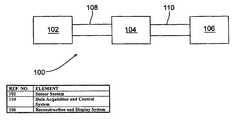
- FIG. 1illustrates a schematic diagram of an exemplary system according to embodiments of the invention.
- FIG. 2Aillustrates a sensor system according to embodiments of the invention.
- FIG. 2Billustrates an example of a ring transducer array.
- FIG. 2Cillustrates an example of a ring transducer assembly.
- FIG. 2Dillustrates an example of a ring transducer in use.
- FIG. 2Eillustrates an example of a paddle transducer array.
- FIG. 2Fillustrates an example of a paddle transducer in use.
- FIG. 2Gillustrates an example of a paddle transducer system incorporating coupling bladders.
- FIG. 3illustrates a schematic diagram of a data acquisition and control system according to embodiments of the invention.
- FIG. 4illustrates two examples of staggered tissue ablation.
- FIG. 5illustrates an example of focused US-based tissue ablation combined with other therapies.
- FIG. 6illustrates a method according to embodiments of the present invention.
- Embodiments of the inventionare directed generally to methods and systems for examining an object under study, such as tissue. Further, embodiments of the invention are directed toward systems and methods that employ acoustic radiation, such as ultrasound, to both diagnose and treat medical pathologies. Such diagnosis and treatment may employ temperature-related parameters to enhance discrimination among various tissue types.
- acoustic radiationsuch as ultrasound
- FIG. 1illustrates one embodiment of a system 100 according to the present invention.
- the system 100includes a sensor system 102 , a data acquisition and control system 104 , and a reconstruction and display computer system 106 , each of which will be described more fully hereinafter.
- the individual componentsare configured for communication via connections 108 , 110 , which may be electrical connections, optical connections, radio frequency (RF) connections, or the like, or any such combination.
- connection 110is an Ethernet connection.
- RFradio frequency
- the sensor system 102may be any of a variety of embodiments that position transducers within sufficient proximity to tissue and thereby provide for the transmission and receipt of acoustic radiation.
- FIG. 2Aillustrates the sensor system in greater detail.
- the sensor system 102includes a plurality of sensors 202 , only one of which is illustrated in FIG. 2A for clarity.
- the sensors 202typically are deployed in an array, as will be described.
- the arrayis configured for movement with respect to tissue under study such that a plurality of 2-D data slices obtained from multiple perspectives may be reconstructed to form a 3-D image.
- Such systemsare more fully described in previously-incorporated in U.S. patent application Ser. No. 10/323,467.
- the sensor arrayis of sufficient size that the sensors may capture a number of 2-D slices without having to move the array with respect to the tissue.
- Each sensor 202is connected to the data acquisition system via interface electronics 204 .
- the interface 204includes a switch 206 that sets the sensor for either of a transmit or receive mode. The position of the switch is determined by a SBC 208 (Single Board Computer), or other appropriate computing device.
- the SBCreceives a signal from the control system instructing that an ultrasonic pulse should be emitted.
- the SBC 208initiates the pulse by sending a signal to a digital-to-analog converter 210 which shapes the pulse.
- the DAC 210sends the signal to a power amplifier 212 that generates sufficient power for the pulse.
- the now-amplified signaltravels through the switch 206 , to the sensor 202 , and into the tissue.
- a transmit systemconsists of digital waveform storage, digital-to-analog conversion, linear power amplification to drive the transducer elements, and a high voltage multiplexer to select the desired element(s).
- the transmit waveformis stored in memory internal to a FPGA (Field Programmable Gate Array).
- the waveformis clocked out to a DAC at a clock rate and timing as determined by the programming of the system, as set up by the prototype user.
- a linear power amplifieris used to provide the necessary element drive.
- High voltage multiplexer switchessuch as the Supertex 20220 eight channel device, may steer the transmit signal to the desired element.
- the transmit systemmay be capable of generating diagnostic waveforms for electrical loopback testing and calibration of the analog transmit/receive (T/R) chain.
- the SBCsets the switch 206 accordingly.
- the sensordetects a signal, which is sent to a filter 214 via the switch 206 .
- the filter 214removes unwanted information, such as interference, and passes the useful information to a signal conditioner 216 .
- the signal conditioner 216may, among other things, convert an analog signal to a digital signal, process the signal to extract useful information from various frequency bands of the signal, and appropriately buffer the information for transmission to the data acquisition system. At the appropriate time, the information may be read out of a buffer by the SBC and transmitted to the data acquisition system.
- the receive signal conditioning path from the transducer elementconsists of a T/R switch, a low noise preamp, TGC (Time Gain Control) amplifier, anti-aliasing low pass filters, and an ADC.
- the T/R switchis a biased diode bridge which blocks large amplitude transmitted signals, but allows receive signals of amplitudes on the order of 1 volt or less to pass to the preamplifier.
- the low noise preamplifier and TGC amplifierare embodied in a number of commercial IC's.
- a devicesuch as the Analog Devices AD8332 may be used to support the required dynamic range.
- the TGC output stagedrives anti-aliasing low-pass filters to a 12-bit ADC, such as the Analog Devices AD19235.
- the ADC datamay be multiplexed in groups of four into the FPGA to allow reduced I/O port usage on the FPGA.
- the FPGAsupports the higher data rates. This data may be written to standard PC133 SDRAM, or similar standard PC RAM to allow for economical data storage. Average writing rates of 40 MW/sec with 64-bit width supports 16 channels data streaming.
- Those skilled in the artwill realize other embodiments of an electrical interface 500 that may perform the function of the present invention.
- the sensor system 102also includes, in some embodiments, a motion control subsystem 218 .
- the motion control subsystem 218receives power, and timing and control information from the data acquisition and control system 104 , as will be described.
- the motion control system 218moves the sensor array with respect to the tissue being examined.
- the sensors 202typically are arranged in an array.
- the arraymay be two-dimensional or three-dimensional.
- a two-dimensional arraymay include 32 sensors arranged in a circular configuration or in an opposing “paddle” configuration, each of which will be described in greater detail.
- the 32-sensor arraysmay be duplicated in the third dimension to create a three-dimensional array.
- Other embodimentsmay include fewer or greater numbers of sensors and may be arranged in different configurations.
- the sensor system 102is a ring transducer system. In another embodiment, the sensor system is a paddle transducer system. An embodiment of a ring transducer system is illustrated in FIG. 2B .
- FIG. 2Billustrates a cross-sectional view of a ring transducer array 220 .
- the ring transducer array 220includes an array of individual sensors 222 and a supporting infrastructure 224 .
- the sensors 222surround, at least partially, an opening 226 in which tissue to be examined may be placed.
- the ring transducer array 220may have a multi-faceted polygonal shape, may be elliptical, or may even not be a closed figure in some embodiments.
- the ring transducer array 220may be mounted in a mechanical system 230 that provides, in some embodiments, motion via a software-controlled stepper motor system or other similar drive system 232 .
- the mechanical system 230includes an acoustic array support 234 , which is adapted to receive a ring transducer acoustic array 220 as a modular insert.
- an appropriately sized acoustic array 220may be selected based on the size of the tissue to be examined so as to provide sufficient acoustic contact between the individual sensors comprised by the array and the tissue to be examined.
- a large acoustic array 220 - 1 and a small acoustic array 220 - 2are illustrated.
- the mechanical system 230including the acoustic array 220 , may operate within a fluid bath, such as a water bath, as will be described.
- the drive system 232may be, for example, a threaded rod that transports the acoustic array 220 vertically with respect to the tissue to be examined. Other types of drive systems are possible and may be designed to transport the acoustic array 220 in different directions or combinations of directions.
- the drive system 232allows the system to acquire a series of ultrasound 2-D slices that combine to make a 3-D data set.
- the ring transducermay be designed according to the following specifications:
- Element width(reference only) 0.5 mm approx Element elevation focus depth 7.5 ⁇ 1 cm Elevation beam width at focus 3 mm
- Nominal element height(reference only) 15 mm
- Electrical interfaceseparate, identical cables for each 16 element sections Mechanical interface ring transducer elements/array sections mounted within a supporting ring structure. This ring structure will be secured in the ring support as illustrated in FIG. 4.4.
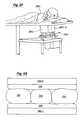
- FIG. 2Dillustrates one possible arrangement of an embodiment of the present invention using a ring transducer system.
- a patient 240lies on an examining table 242 .
- the tissue to be examinedin this case a breast 244 , protrudes through a hole in the examining table.
- a ring transducer 246surrounds the breast.
- a fluid bath 248aid in acoustically coupling the transducer to the breast.
- a drive system 250moves the transducer with respect to the breast.
- the drive system 250provides electrical control of vertical motion, but is otherwise fixed within the fluid bath.
- the transducer cablingmay be routed over the upper edge of the water bath.
- the lead screw actuator for the vertical drivemay be the sole fluid boundary penetration for this assembly.
- the motor drive for the assemblymay be below the fluid bath. Electrical cables for limit switches, etc. located inside the fluid bath may also be routed over the upper edge of the bath.
- FIG. 2Eillustrates a cross-sectional view of a paddle transducer array 260 .
- the sensors 262 of the paddle transducer array 260surround, at least partially, an opening 264 in which the tissue to be examined may be placed.
- the paddle transducer array 260includes two individual paddles 266 that may be adjusted with respect to one another.
- the paddle transducer array 260may have a different acoustic geometry than the ring transducer array 220 , but may be designed to be electrically equivalent. That is, the paddles 266 of a paddle architecture may function with the same electronic subsystem as the ring transducer array 220 .
- a paddle transducer systemmay be designed according to the following specifications:
- FIG. 2Fillustrates one possible arrangement of an embodiment of the present invention using a paddle transducer system.
- a patient's breastis examined.
- the breastis placed between two paddles 280 of the paddle transducer array 282 .
- the paddles 280may be adjusted to directly contact the tissue, thereby providing sufficient acoustic coupling to avoid the use of a fluid bath.
- This embodimentmay, however, benefit from some type of medium (e.g., gel) to enhance the acoustic coupling.
- the paddle transducer systemmay be configured for movement with respect to the tissue to be examined or may be fixed. Embodiments of a paddle transducer system are described more fully in previously-incorporated U.S. patent application Ser. No. 10/323,467.
- FIG. 2Gillustrates an example of a paddle transducer system incorporating acoustically-coupling, pliable bladders.
- the bladderswhich are filled with a medium that is acoustically matched to the transmission medium improve contact between the tissue under examination and the transducer array.
- lateral bladders 290extend along the paddles 280
- removable bladders 292are placed on either side of the tissue under examination 294 .
- FIG. 3illustrates one exemplary embodiment of a data acquisition and control system 104 according to embodiments of the present invention.
- the data acquisition and control system 104includes one or more interface connections 302 between individual sensors or groups of sensors in the sensor system 102 and channel boards 304 .
- the channel boards 304receive timing and control signals from a timing and control subsystem 306 , as will be described, and thereby operate the sensors of the sensor system.
- the channel boards 304are also interfaced to a backplane 308 .
- the data acquisition and control system 104also includes a power subsystem 310 , and a computer subsystem 312 .
- Each channel board 304provides for transmit excitation, signal conditioning, and data storage for one or more sensors.
- Each boardmay plug into an appropriately-configured backplane 308 .
- Each boardmay function independently of other channel boards in the system.
- each boardcontains an FPGA which provides all of the real time control of timing, transmit, acquisition functions, and data memory interface.
- the FPGA firmwareis stored in flash memory on the board, or downloaded from the Compact PCI computer.
- the FPGAgenerates all clocks and timing local to the channel board from the system clock and synchronization provided to each board.
- the timing and control subsystem 306provides basic clock and synchronization information among the multiplicity of independent channel board assemblies.
- the signals, programmed under control from the computer 312are synchronized among all of the channel boards.
- the boardsthen each generate locally the timing, waveforms, and acquisition appropriate for the programmed acoustic line.
- the systemmay be capable of external triggering and gating. This capability allows for cardiac gated studies and single shot experiments as example uses of this mode.
- the power subsystem 310supports electronics and control for a minimum of 256 element transducers and associated support electronics in a specific embodiment.
- the power systemmay provide isolation to appropriate medical safety standards, especially in embodiments designed for human patients.
- the systemmay operate on standard 115VAC, 60 Hz nominal AC mains.
- the back endmay consist of a “standard” Intel-based computer board in compact PCI form factor.
- Such computer boardsare available in configurations that support standard, commercial network and computer systems and software to allow networking with the reconstruction/display workstation.
- an optical Ethernet link 314may connect the data acquisition and control system to the reconstruction and display computer system 106 .
- the bulk of the data acquisition and control system 104is contained in a Compact PCI chassis.
- Commercial mechanical chassis assemblies, backplanes and Intel-based computer boardsare available in this standard, allowing the system to exist on a standard platform base.
- the transmit/receive (T/R) section of the electronic subsystemis divided into multiple, identical board assemblies with 16 channels receive channels and 1-8 transmit amplifiers. Since certain operating modes may have only one acoustic element transmitting at a time, there may be relatively few transmit amplifiers, which are multiplexed to the transducer elements with high voltage switches.
- Each channel boardhas its own transmit circuitry in order to avoid signal interconnections among the channel boards.
- Each boardhas an independent cable to its set of transducer acoustic elements. Except for clocks, timing synchronization, and power, each board assembly will function independently of other channel boards. Each of these boards has a PCI backplane interface to the Compact PCI computer board. Each channel provides a wide dynamic range acquisition system with real-time, RF data storage in RAM local to the channel board. Sufficient RAM memory is provided to store a study with a minimum of 100 2-D ultrasound slice data. Once stored, the data may be uploaded to the computer system without any real time restrictions. However, computational time requirements may constrain or dictate certain aspects of the computer system. In addition to changing the transducer, increasing the array size may be accommodated by adding additional channel boards, providing the clocks with timing and power, with the interfacing being supported within the compact PCI chassis.
- the reconstruction and display computer system 106may comprise any of a variety of computing systems.
- the reconstruction and display computer systemmay be the operator system described more fully in previously-incorporated U.S. patent application Ser. No. 10/323,467. Those skilled in the art will realize other alternative embodiments.
- the diagnostic component of the present inventionextends the capabilities of a variety of other devices and techniques, to include temperature-related diagnostic parameters with treatment delivery, monitoring, interactive control and/or automation.
- Such robust ultrasound (“US”) algorithms and recent imaging achievements with fewer transducer pairsi.e., sparse array
- Embodiments of the present inventionextend known diagnostic parameters of ultrasonic fields (i.e., reflectivity, sound speed, attenuation, etc.) to include differential tissue responses to heating and/or cooling of tissue (i.e., additional cancer discrimination from benign tissue). For example, accurate temperature measurements during treatment (e.g., conversion of sound speed) confirms tumor ablation margins and also allows accurate fat-suppression imaging to reduce imaging time and data storage.
- Thermal treatment planningis possible through continuous monitoring of tissue response to thermal ablation (i.e., heat ablation>50° C., or cryotherapy ⁇ 20° C., or associated recovery from cooling/heating). Rapid imaging ( ⁇ 1 sec.) during treatment thus provides additional characterization of cancer margins during treatment (i.e., temperature changes in US parameters).
- the permanent changes in several thermodynamic and acoustic parametersprovide confirmation of thorough treatment effect while the patient is still on the table, as well as for subsequent follow-up. Beyond high temperature ablation, several other uses are within the scope of the invention.
- Current hyperthermia (i.e., 41-44° C.) treatment systemscould be used in combination with radiation therapy to avoid invasive thermometry.
- advanced diagnostic functions with focused ultrasoundtarget the delivery of chemotherapy, or genetic, agents contained in microbubbles “tuned” to burst at appropriate US energy and/or tumor locations.
- “Dynamic focusing” in terms of a method and apparatus for generating destructive US energy by transmitting a time-reversed field to their original scattering point within a mediumis described more fully in previously-incorporated U.S. Patent No. 6,490,469. Diagnostic parameters according to embodiments of the present invention may be used to improve dynamic focusing-based thermal therapy as described in more detail herein.
- the apparatus described abovehas the capability of performing any or all of the following:
- HIFUhigh intensity focused ultrasound
- Embodiments of the present inventionthat generate an US-based thermal dosimetry system in a single device for improved safety and reduced treatment times are well founded. Namely, three methods have been used to predict tissue damage:
- Temperature and dosimetryare independent of inhomogeneities of acoustic properties, but recent power calculations have allowed reasonable estimates despite power prediction differences between tissue types.
- Thermal doseshows good correlation with standard hyperthermia treatments for planned outcomes of 100% necrosis (i.e., 43° C. when delivered for 240 minutes). Conversion to predict HIFU outcomes yielded the following boundary criteria for unaffected (i.e., reversible) and thoroughly ablated tissue:
- Embodiments of the present inventionnot only use the temperature and dose profiles but have improved power estimates due to thorough knowledge of the US field.
- Embodiments of the inventioninclude MRI-based thermal dosimetry for treatment planning in connection with US imaging and/or therapy.
- thermoacoustic computed tomographyspecifically relies upon the greater heating response of tumors over benign tissue. Since breast tumors appear to have a higher bound-water fraction than benign tissue (i.e., 0.85 vs. 0.75, resp.), tissue heating by pulsed radio-frequency (RF) energy would be greater, and/or faster, for tumors. Only ⁇ 0.25° C. tissue heating caused mechanical expansion of tissue that initiated pressure waves. The waves propagated through the tissue as sound and were detected by US transducers.
- RFradio-frequency
- Thermoacoustic CT of the breastMedical Imaging 2002: Physics of Medical Imaging (SPIE 2002). Paper 4682-55. San Diego, Calif., herein incorporated by reference in its entirety) thoroughly documents the relationships between shear modulus, acoustic strain wave frequency, resolution, phase changes and temperature. It has thus been identified that the premise of elastographic tumor discrimination may additionally include effects from temperature-related changes. Elastography thus serves as an excellent post-ablation assessment of irreversible tissue damage that will complement other US parameters (below). As imaging speed of vibrational sequences improves, dynamic elastography will provide additional on-line evaluation during treatments.
- Embodiments of the present inventionthus use a technique that may be characterized as “fat-suppression” breast imaging. Advanced diagnostic parameters of embodiments of the present invention then focus only on the non-fatty tissues, thereby reducing scanning times and data storage. Fluids also appear to have a different heating response than solid tissues, but the heating response of human breast cysts may relate to their lipid or serous content (i.e., ‘oil’ vs. ‘simple’ breast cysts).
- the non-linear aspect (i.e., B/A) of the heating responsewas different for liver and multiple myeloma tumor, despite their similar sound speeds.
- the value of B/Ais thus related to other thermodynamic parameters (i.e., Grusneissen parameters, Rao and Wade's constants), making it possible to obtain further characterization of the quasicrystalline structure (morphology) of tissues and their cohesive forces.
- thermodynamic parametersi.e., Grusneissen parameters, Rao and Wade's constants
- a consequence of large-aperture diagnostic capabilities according to embodiments of the present inventionis that differential tumor response to heating is greatly enhanced (i.e., m ⁇ sec ⁇ 1 ⁇ ° C. ⁇ 1 , B/A, or other thermodynamic parameters).
- Final HIFU ablation areashave been characterized by permanent, marked increases in attenuation. To a lesser degree, sound speed still showed significant increases over pretreatment values. Final lesion attenuation and sound speed may thus be used to complement elastography and USAE to define irreversible tissue damage.
- Embodiments of the inventionprovide for ultrasound-stimulated vibro-acoustic spectrography using diagnostic parameters of the ultrasound field.
- these teachingsmay be used to detect breast microcalcifications and for temperature monitoring and characterization of HIFU ablation regions.
- These joint conceptsare integrated into the system described above with the previously-described hydrophone-type sensor(s) in the transducer array.
- USAEapplies a harmonic excitation inside a target through the application of two focused beams that oscillate at slightly different frequencies.
- the US fieldsonly overlap at the target, causing it to locally vibrate at the beat frequency.
- the response recorded at the hydrophonethen depends on the local acoustic and mechanical properties of the target tissue.
- Tissue properties of stiffness and absorptioninfluence the magnitude of the USAE and are used to detect coagulation.
- One reportdemonstrates the dual function of focused ultrasound transducers as an USAE interrogation source, both during and after ablation.
- the 50-msec imaging pulsewas interspersed between the focused US pulses and allowed intermittent monitoring of ablations in progress.
- USAE amplitude measurementssuggested that the transition to irreversible tissue damage at the point of coagulation corresponded with ⁇ 55° C., when muscle tissue typically coagulates.
- the near-linear correlation of USAE amplitude with temperaturewas also lost at 55° C. and correlates with tissue stiffness, marked changes in absorption and shear modulus.
- at least one sourcealso noted an interesting departure from the coagulation theory for fat, which continued to have USAE correlation beyond coagulation temperatures.
- fat-suppression imagingmitigates or avoids the USAE irregularities caused by adjacent fat.
- Sonoporationor the “opening” of cell membranes, in response to low amplitude ultrasound can be either permanent or temporary. Permanent damage to the cell membrane results in eventual cell lysis, whereas temporary damage often causes the membrane “holes” to “re-seal”. It has been noted that be temporary damage, or reparable sonoporation, takes place in the presence of injected microbubbles at acoustic pressure amplitudes of 0.1-0.12 MPa for 1 and 2.25 MHz, respectively. While contrast agents are becoming standard practice in other countries, none are currently Food and Drug Administration (FDA) approved within the United States. Therefore, if reparable sonoporation even occurs with current diagnostic ultrasound levels, new focusing possibilities for delivering targeted treatments may help justify their use.
- FDAFood and Drug Administration
- ultrasound emitterse.g., 10-300 emitters.
- any number of emitterscould be added to the ring, or rewiring of the current transducer boards to allow dual function of the transducers to both send and receive.
- the sequenced emitting of ultrasound pulsesbecomes a function of software control, utilizing the model-based focusing technique.
- transducer configuratione.g., circular array, or opposing paddle geometry
- any body part containing a tumorcould be effectively addressed by sonoporation and/or ablative energy treatments according to embodiments of the present invention.
- an interleaved scanning techniquecould easily be implemented for either sonoporation or ablative energy treatments. Similar scanning techniques have already been described with focused ultrasound using MRI guidance for ablation of breast fibroadenomas and cancer.
- the purpose of interleaved techniquesallow imaging-treatment-imaging sequences to result in localization-treatment-monitoring, respectively.
- the delivery of interlaced sequenceswould become a function of the speed and accuracy of the equipment. In this manner, treatments will be administered at the rate of imaging localization, preventing inadvertent treatment due to patient motion within the time sequence to verify localization.
- the estimated 40 millisecond scan time for propagation and reception of an ultrasound pulsemay then be followed by a treatment pulse from multiple transducers (diagnostic or therapeutic energies), resulting in immediate focusing to the selected target within a similar 40 millisecond return time.
- Computer processingalso allows a subsequent monitoring pulse to be quickly fired after the initial image and treatment pulse.
- a subsequent monitoring pulsewithin ⁇ 150 milliseconds (i.e., 40+40+40+ . . . ), extremely fast processing could produce images of the target and treatment outcome.
- Image reconstruction timescould be markedly reduced by limiting visualization to the target region (e.g., 1-10 cc), focusing assistance needs (“seeds”, needle/US emitter discussed hereinafter) and margin auto-detection algorithms.
- Such millisecond accuracy in the delivery of subsequent pulseswould not only help alleviate inadvertent patient motion, but also unavoidable motion from cardiac or respiratory changes.
- any distortions of the ultrasound field from the initial treatment pulsei.e., changes in monitored ultrasound parameters of sound speed, attenuation, reflectivity, etc.
- the software controltherefore may rely upon the computer workstation to switch between algorithms which serve a diagnostic function and those which trigger the focused ultrasound sequences. Intermittent non-invasive temperature monitoring could thus use an intermittent data set processed by the sound speed algorithm, where as a margin-based assessment for anatomic treatment accuracy would intermittently employ a reflective algorithm (i.e., migration or full aperture tomography).
- a reflective algorithmi.e., migration or full aperture tomography
- assisted focused ultrasound deliveryi.e., pretreatment deposition of tumor marking “seeds”, or a needle intimating a localizing ultrasound pulse
- the algorithm for “blind” focusing upon a dominant scatterercould be much faster than a model-based algorithm requiring several iterations to achieve accurate spatial localization.
- time-reversal ultrasound focusingcan be simplified and markedly expedited by allowing ablations to proceed around a dominant reflector within the ultrasound field.
- a highly reflective ultrasound “seed”could be placed within the tumor prior to the focused ultrasound treatment session.
- an ultrasound emitting needlecould be placed within the tumor immediately prior to initiation of the focused ultrasound treatment session.
- Embodiments of the present inventioninclude a treatment planning workstation.
- Softwarecurrently exists for accurate 3-D volumetric assessments of tumor margins overtime. This type of tiny margin analysis would be an example of the first step in creating a tailored pulse sequence to cover the entire tumor volume.
- the next stepwould be similar to radiation therapy planning software which tries to minimize side effects of the radiation in adjacent normal structures as it is delivered through predetermined “portals”. Namely, multiple repeating US pulse sequences using the previously described image-treat alternating pattern would be distributed across the tumor volume to cover all visible margins.
- treatmentwould generally include up to 1 cm beyond the tumor to achieve “surgical margins”. The size of each treatment zone during a single pulse sequence could be altered as needed for either their low power or high-power treatment options.
- a high-power ablationmay choose to stagger each successive pulse 600 - 1 , 600 - 2 , 600 - 3 , 600 - 4 . . . (in turn) in an opposing fashion across the tumor volume 602 in order to avoid heat-induced alterations in the sound propagation profiles (e.g., air bubbles from cavitation).
- the accuracy in delivering these ablation zonesagain relates to the interleaved imaging-treatment pulse sequences which may be predetermined from a treatment “planning scan”.
- the 3-D spatial accuracyderives from matching the preoperative study with the obtained interleaved images using the following suggested guidance options:
- a larger tumor 702may, have the majority of its volume rapidly covered by percutaneous, ablation probes 704 placed strategically within the mass.
- these probe placementsrequire technical accuracy that may be difficult to achieve, or the ablation 706 could become altered by adjacent heat sink effect from bordering vessels, such that portions of the tumor 702 may be left untreated.
- These untreated tumor margins 708or those coming very close to the treatment margin 710 , may be easily recognized using the previously noted temperature monitoring functions (e.g., sound speed) and parameters which evaluate ablation completeness (e.g. attenuation, USAE, elastography, etc.). Therefore, the smaller ablations 712 by focused ultrasound are shown to cover these untreated areas in the same therapy session.
- the “positive margins”, known to occur with current ablationscould be treated at a later time by focused US according to embodiments of the present invention.
- cryotherapy and RF probeshave thermocouples contained within their tips-but lack a-non-invasive mechanism to control the extent of their ablation.
- the focused ultrasound componentcould be used to not only “touch-up” incomplete margins as seen in FIG. 5 , but also to prevent the inadvertent extension of cytotoxic ice formation by standard cryotherapy probes. This would lead to tailored “sculpting” of an ice ball in order to better conform to the contours of any delicate adjacent structures. For heat-based ablations, this degree of counteractive modulation of the major ablation zone may not be possible, but the major ablation can be terminated when one of its ablation margins reaches its targeted extent. Any remaining tumor ram could then be handled by the “touch-up” methodology seen in FIG. 5 .
- the computer workstationuses interleaved scanning sequences with focused ultrasound as a stand-alone modality, or in combination with other ablative modalities noted above, the computer electronics required to control the switching between the algorithms are predominantly software driven. Driving of the transducers, data collection, storage and manipulation can be rapidly switched for their appropriate function.
- FIG. 6illustrates a method 800 according embodiments of the present invention.
- the methodmay be implemented in the system of FIG. 1 or similar system.
- FIG. 6is to be considered exemplary.
- a transducer arrayis positioned in relation to tissue to be examined.
- the transducer arraymay be a ring transducer, paddle transducers or other suitable transducer array. Further, the transducer array may be a 1-dimensional transducer array, a 2-dimensional transducer array, or a 3-dimensional transducer array.
- the transducer arrayis configured to both transmit and receive acoustic radiation.
- the systemis configured for both diagnosis and therapy.
- the transducer arrayhas a small number of transducers, for example, 11.
- the simultaneous addressable emitter arraysboth have a large number of transducers, for example several thousand.
- the transmittersboth transmit and receive. Many other examples are possible and not necessarily bounded by these two examples.
- acoustic imagingis performed.
- acoustic radiationis directed at the tissue from transducers in the transducer array (block 805 ) and the resulting scattered radiation is received by other transducers in the array (block 806 ). In this way, an image of the tissue is obtained (block 807 ).
- an acoustic radiation generating probefor example an interstitial needle, is placed in the tissue (block 808 ) and acoustic radiation may be emitted from (block 810 ). The scattered radiation is then received at the transducers to form an image. In either of these cases, the image is, for example, a 3-dimensional image formed by compiling multiple 2-dimensional images.
- the imagemay be enhanced in any of the previously-described ways.
- the temperature of the tissuemay be either internally or externally altered to change the acoustic properties of the tissue (block 812 ).
- a sound speed algorithmmay be employed to further discriminate among various tissue types based on this acoustic property.
- the imagealso may be enhanced by placing a highly reflective “seed” into a particular area of the tissue of interest (block 814 ), for example a tumor, prior to directing the acoustic radiation at the tissue.
- therapyis performed on at least a portion of the tissue.
- the therapymay be any of a variety of different types of therapy, some of which were discussed herein previously.
- a tumor located in the tissuemay be treated with cryogenic (block 822 ) or ablative (block 823 ) therapies.
- the ablative therapymay involve the focusing of US acoustic radiation on a region of the tissue using time-reversal techniques as was described previously. Time-reversal focusing techniques may involve model-based focusing and/or “blind” focusing, both of which were described in more detail above.
- blind focusingthe process may employ the use of natural body landmarks, such as bone, to direct the acoustic radiation.
- Blind focusingalso may employ a reflective “seed” deposited within the target region (block 824 ).
- interstitial needles, or other probesare used which may: emit US radiation, measure temperature, and/or provide therapy, such as cryogenic therapy, radio frequency therapy, microwave therapy, or the like (block 826 ). Many other examples are possible.
- a personsuch as a physician, may assist in defining the target region by supplying information to the diagnosis/treatment device.
- the target regionmay be defined with the assistance of software. In some cases, these two examples are combined.
- information developed from the operation at block 804may be used.
- targeting informationis supplied to the device from other sources.
- the targetis defined with respect to other objects at a known location in the tissue, again possibly employing information developed during the operation at block 804 . Combinations of these examples also are possible as are many other examples.
- the therapy provided at block 820may involve sonoporation (block 830 ). This may involve low power focused US and/or high-re power focused US. This treatment may be combined with microbubbles, as previously described, to deliver chemical treatment to sonoporated cells (block 834 ).
- the therapymay involve any combination of the foregoing.
- a tissue areamay be treated with cryogenic therapy while regions around the cryogenically-treated area are treated with focused US. Many other such examples are possible.
- the therapy provided at block 820may be directed toward are area of active hemorrhage. This may involve directing focused US using any of the previously-described techniques or may employ Doppler-based blind focusing. Other examples are possible.
- the therapy provided at block 820may be followed by a subsequent diagnostic session that uses US to determine the effect of the therapy. This may take place at block 860 , as shown and may include any of the diagnostic processes described above with respect to block 804 . In some examples, the operations of blocks 820 and 860 may be repeated any number of times to incrementally treat the tissue by iteratively treating the tissue then assessing the effect of the treatment. Many other examples are possible.
Landscapes
- Health & Medical Sciences (AREA)
- Life Sciences & Earth Sciences (AREA)
- General Health & Medical Sciences (AREA)
- Physics & Mathematics (AREA)
- Veterinary Medicine (AREA)
- Nuclear Medicine, Radiotherapy & Molecular Imaging (AREA)
- Public Health (AREA)
- Radiology & Medical Imaging (AREA)
- Engineering & Computer Science (AREA)
- Biomedical Technology (AREA)
- Animal Behavior & Ethology (AREA)
- Medical Informatics (AREA)
- Molecular Biology (AREA)
- Surgery (AREA)
- Heart & Thoracic Surgery (AREA)
- Pathology (AREA)
- Biophysics (AREA)
- Acoustics & Sound (AREA)
- Gynecology & Obstetrics (AREA)
- Surgical Instruments (AREA)
- Ultra Sonic Daignosis Equipment (AREA)
Abstract
Description
| Number of elements | 256 |
| Geometry | equally spaced on 15 cm diameter circle |
| (1.84 mm pitch), or alternately, on linear | |
| segments of a 16-sided inscribed polygon. In | |
| either case, the actual positions of the | |
| transducer elements may be known within | |
| 0.2 mm within the imaging plane of the | |
| transducer. | |
| Center frequency f0 | 2 MHz within ±5% average over all |
| elements | |
| within ±10% for any individual element | |
| Bandwidth | 60% f0 minimum, each element (−6 db |
| transmit/receive) | |
| Pulse ringdown (−20 db) | 1.8 us maximum |
| Element sensitivity variation over array | within 3 db band |
| Element angular response (at f0 in plane of | −6 db max. at ±60 degrees |
| circle) | |
| Element width (reference only) | 0.5 mm approx |
| Element elevation focus depth | 7.5 ± 1 cm |
| Elevation beam width at focus | 3 mm |
| Nominal element height (reference only) | 15 mm |
| Electrical interface | separate, identical cables for each 16 |
| element sections | |
| Mechanical interface | ring transducer elements/array sections |
| mounted within a supporting ring structure. | |
| This ring structure will be secured in the ring | |
| support as illustrated in FIG. 4.4. | |
| Center frequency f0 | 2 MHz within ±5% average over all |
| elements | |
| within ±10% for any individual element | |
| Bandwidth | 60% f0 minimum, each element (−6 db |
| transmit/receive) | |
| Pulse ringdown (−20 db) | 1.8 us maximum |
| Element sensitivity variation over array | within 3 db band |
| Element angular response (at f0 in plane of | −6 db max. at ±60 degrees |
| circle) | |
| Element width (reference only) | 0.5 mm approx |
| Element elevation focus depth | 7.5 ± 1 cm |
| Elevation beam width at focus | 1.5 mm |
| Nominal element height (reference only) | 15 mm |
| Electrical interface | separate, identical cables for each 16 |
| element sections | |
| Mechanical interface | paddle arrays constructed in a modular |
| fashion to allow simple mounting in the | |
| paddle mechanical assembly, and to allow | |
| relatively simple change of transducer arrays | |
| with minimal or no change in the basic | |
| paddle mechanical structure and control | |
| mechanisms. | |
- A. Directly measure the parameters of the acoustic field using a system according to the present invention.
- B. Markedly reduce scan times and data storage by “fat-suppression” imaging. Static, or temperature-related dynamic, changes in US parameters first identify fatty tissues, then tailor subsequent cancer discrimination sequences to separation of benign and malignant responses.
- C. Monitor temperature changes in all areas of the imaging field to <1° C. via thermoacoustic properties of the ultrasound field during heating and cooling cycles of an ablation modality (i.e., all heating sources, as well as cryotherapy, or freezing).
- D. Deliver focused US energy to any region of a specified target (i.e., tumor area) and measure resultant changes in dynamic—acoustic parameters in order to:
- 1. Provide further differentiation of tumor from normal tissue by their heating or cooling responses.
- 2. Monitor target temperature for automatic downregulation/itermination of ablation, (heating or cooling) to that region
- 3. Treatment protocol development: Selectively stop heating in one location and begin in another according to temperature or anatomy, thus allowing selective ablation of:
- a. Tumor vascularity (i.e., “feeder” vessels) to decrease convective cooling of flowing blood and improve intratumoral heating profile.
- b. All tumor contours for uniform ablation
- c. Peripheral viable tumor while avoiding regions of central tumor necrosis not requiring intensive treatment.
- d. Regions needing immediate re-treatment due to tumor heterogeneity and/or ineffective initial heating cycle.
- E. Post-ablation: re-assess final acoustic parameters to confirm thorough coagulation necrosis and any residual tumor viability over time
- F. Ensure greater safety and reduced treatment times using Dynamic Focusing since thermal build-up from cumulative exposure is avoided (i.e., multiple transducer focusing rather than using a single emitter).
MRI Temperature Monitoring and High-Intensity Focused Ultrasound
| TABLE I | ||||
| Tissue | Temp (° C.) | m · sec−1· ° C.−1 | ||
| Water | 24–36 | 2.7 | ||
| 0.9% NaCl | 24–40 | 1.8 | ||
| Liver | 24–36 | 1.3 | ||
| Breast parenchyma | 24–36 | 1.3 | ||
| Breast fat | 32–36 | −10.0 | ||
| Breast fat | 36–43 | 4.5 | ||
| Glycerol | 20–30 | −2.2 | ||
| Breast fat | 30–37 | −6.0 | ||
| Multiple myeloma | 22–37 | 1.3 | ||
Claims (54)
Priority Applications (1)
| Application Number | Priority Date | Filing Date | Title |
|---|---|---|---|
| US10/440,427US8376946B2 (en) | 2002-05-16 | 2003-05-16 | Method and apparatus for combined diagnostic and therapeutic ultrasound system incorporating noninvasive thermometry, ablation control and automation |
Applications Claiming Priority (4)
| Application Number | Priority Date | Filing Date | Title |
|---|---|---|---|
| US38102202P | 2002-05-16 | 2002-05-16 | |
| US10/323,354US7285092B2 (en) | 2002-12-18 | 2002-12-18 | Computerized ultrasound risk evaluation system |
| US10/323,467US6984210B2 (en) | 2002-12-18 | 2002-12-18 | Diagnostic analysis of ultrasound data |
| US10/440,427US8376946B2 (en) | 2002-05-16 | 2003-05-16 | Method and apparatus for combined diagnostic and therapeutic ultrasound system incorporating noninvasive thermometry, ablation control and automation |
Related Parent Applications (2)
| Application Number | Title | Priority Date | Filing Date |
|---|---|---|---|
| US10/323,354Continuation-In-PartUS7285092B2 (en) | 2002-05-16 | 2002-12-18 | Computerized ultrasound risk evaluation system |
| US10/323,467Continuation-In-PartUS6984210B2 (en) | 2002-05-16 | 2002-12-18 | Diagnostic analysis of ultrasound data |
Publications (2)
| Publication Number | Publication Date |
|---|---|
| US20040030227A1 US20040030227A1 (en) | 2004-02-12 |
| US8376946B2true US8376946B2 (en) | 2013-02-19 |
Family
ID=29554176
Family Applications (1)
| Application Number | Title | Priority Date | Filing Date |
|---|---|---|---|
| US10/440,427Active2029-04-29US8376946B2 (en) | 2002-05-16 | 2003-05-16 | Method and apparatus for combined diagnostic and therapeutic ultrasound system incorporating noninvasive thermometry, ablation control and automation |
Country Status (4)
| Country | Link |
|---|---|
| US (1) | US8376946B2 (en) |
| EP (1) | EP1551303A4 (en) |
| AU (1) | AU2003261073A1 (en) |
| WO (1) | WO2003096883A2 (en) |
Cited By (14)
| Publication number | Priority date | Publication date | Assignee | Title |
|---|---|---|---|---|
| US20070239077A1 (en)* | 2006-03-09 | 2007-10-11 | Haim Azhari | Method and system for lipolysis and body contouring |
| US20110288410A1 (en)* | 2010-02-22 | 2011-11-24 | Speyer Gavriel A | Methods and systems for diagnostic ultrasound based monitoring of high intensity focused ultrasound therapy |
| US20110291654A1 (en)* | 2010-05-31 | 2011-12-01 | Cheng Ni | Method for reducing magnetic resonance temperature measurement errors |
| EP2868279A1 (en)* | 2013-10-31 | 2015-05-06 | Canon Kabushiki Kaisha | Subject information acquisition apparatus |
| US9636073B2 (en) | 2012-12-21 | 2017-05-02 | Caperay Medical (Pty) Ltd. | Dual-modality mammography |
| US9726647B2 (en) | 2015-03-17 | 2017-08-08 | Hemosonics, Llc | Determining mechanical properties via ultrasound-induced resonance |
| US10405773B2 (en) | 2014-12-19 | 2019-09-10 | General Electric Company | Tissue delineation and characterization in magnetic resonance imaging |
| US10962524B2 (en) | 2011-02-15 | 2021-03-30 | HomoSonics LLC | Characterization of blood hemostasis and oxygen transport parameters |
| US11099075B2 (en) | 2017-11-02 | 2021-08-24 | Fluke Corporation | Focus and/or parallax adjustment in acoustic imaging using distance information |
| US11209306B2 (en) | 2017-11-02 | 2021-12-28 | Fluke Corporation | Portable acoustic imaging tool with scanning and analysis capability |
| US11439308B2 (en)* | 2020-07-13 | 2022-09-13 | GE Precision Healthcare LLC | Methods and systems for thermal monitoring of tissue with an ultrasound imaging system |
| US11762089B2 (en) | 2018-07-24 | 2023-09-19 | Fluke Corporation | Systems and methods for representing acoustic signatures from a target scene |
| WO2025090692A1 (en) | 2023-10-25 | 2025-05-01 | University Of Rochester | Acoustic wave shaping through defined concentric closed shapes |
| US12379491B2 (en) | 2017-11-02 | 2025-08-05 | Fluke Corporation | Multi-modal acoustic imaging tool |
Families Citing this family (152)
| Publication number | Priority date | Publication date | Assignee | Title |
|---|---|---|---|---|
| US6050943A (en) | 1997-10-14 | 2000-04-18 | Guided Therapy Systems, Inc. | Imaging, therapy, and temperature monitoring ultrasonic system |
| US9402601B1 (en)* | 1999-06-22 | 2016-08-02 | Teratech Corporation | Methods for controlling an ultrasound imaging procedure and providing ultrasound images to an external non-ultrasound application via a network |
| US20040015079A1 (en) | 1999-06-22 | 2004-01-22 | Teratech Corporation | Ultrasound probe with integrated electronics |
| JP2003513691A (en) | 1999-10-25 | 2003-04-15 | シーラス、コーポレイション | Use of focused ultrasound to seal blood vessels |
| US6626855B1 (en)* | 1999-11-26 | 2003-09-30 | Therus Corpoation | Controlled high efficiency lesion formation using high intensity ultrasound |
| US7914453B2 (en) | 2000-12-28 | 2011-03-29 | Ardent Sound, Inc. | Visual imaging system for ultrasonic probe |
| JP4781548B2 (en)* | 2001-03-14 | 2011-09-28 | 浜松ホトニクス株式会社 | Breast cancer detection device |
| DE10151987C2 (en)* | 2001-10-22 | 2003-11-06 | Fraunhofer Ges Forschung | Preparation of the selection of control variables for a dose distribution of a radiation device to be set in time and space |
| AU2003219843B2 (en)* | 2002-02-20 | 2009-04-23 | Medicis Technologies Corporation | Ultrasonic treatment and imaging of adipose tissue |
| EP1551303A4 (en) | 2002-05-16 | 2009-03-18 | Karmanos B A Cancer Inst | COMBINED DIAGNOSTIC METHOD AND SYSTEM AND ULTRASONIC TREATMENT SYSTEM INCLUDING NON-INVASIVE THERMOMETRY, CONTROL AND AUTOMATION OF ABLATION |
| EP1493500B1 (en)* | 2003-07-01 | 2020-12-09 | Esaote S.p.A. | Electronic array endocavity probe for ultrasonic imaging |
| US8390181B2 (en)* | 2003-07-01 | 2013-03-05 | Esaote S.P.A. | Electronic array probe for ultrasonic imaging |
| US20090076391A1 (en)* | 2003-10-15 | 2009-03-19 | Der-Yang Tien | Method and system for leading macromolecule substances into living target cells |
| US20110071381A1 (en)* | 2003-10-15 | 2011-03-24 | Robert Tien | Method and system for leading macromolecule substances into living target cells |
| TWI243696B (en)* | 2003-10-15 | 2005-11-21 | Der-Yang Tien | System for introducing macromolecule substance into living target cell |
| US7662114B2 (en)* | 2004-03-02 | 2010-02-16 | Focus Surgery, Inc. | Ultrasound phased arrays |
| WO2005107601A2 (en)* | 2004-05-06 | 2005-11-17 | Focus Surgery, Inc. | Method and apparatus for the selective treatment of tissue |
| US8235909B2 (en) | 2004-05-12 | 2012-08-07 | Guided Therapy Systems, L.L.C. | Method and system for controlled scanning, imaging and/or therapy |
| NL1026492C2 (en)* | 2004-06-24 | 2005-12-28 | Pan Consult B V | Device for ultrasound irradiating a target area in a human or animal body. |
| CN1976634B (en) | 2004-06-28 | 2012-07-11 | 皇家飞利浦电子股份有限公司 | Systems and methods for amplifying transmitted waveforms generated by an ultrasound system |
| CN101090670B (en)* | 2004-08-17 | 2010-05-26 | 特赫尼恩研究与发展基金有限公司 | Ultrasound imaging-guided tissue destruction systems and methods |
| US9011336B2 (en)* | 2004-09-16 | 2015-04-21 | Guided Therapy Systems, Llc | Method and system for combined energy therapy profile |
| US7393325B2 (en) | 2004-09-16 | 2008-07-01 | Guided Therapy Systems, L.L.C. | Method and system for ultrasound treatment with a multi-directional transducer |
| US7824348B2 (en) | 2004-09-16 | 2010-11-02 | Guided Therapy Systems, L.L.C. | System and method for variable depth ultrasound treatment |
| US20120165848A1 (en) | 2010-08-02 | 2012-06-28 | Guided Therapy Systems, Llc | System and method for treating cartilage |
| US7530958B2 (en)* | 2004-09-24 | 2009-05-12 | Guided Therapy Systems, Inc. | Method and system for combined ultrasound treatment |
| US10864385B2 (en) | 2004-09-24 | 2020-12-15 | Guided Therapy Systems, Llc | Rejuvenating skin by heating tissue for cosmetic treatment of the face and body |
| US8535228B2 (en) | 2004-10-06 | 2013-09-17 | Guided Therapy Systems, Llc | Method and system for noninvasive face lifts and deep tissue tightening |
| US8444562B2 (en) | 2004-10-06 | 2013-05-21 | Guided Therapy Systems, Llc | System and method for treating muscle, tendon, ligament and cartilage tissue |
| US11883688B2 (en) | 2004-10-06 | 2024-01-30 | Guided Therapy Systems, Llc | Energy based fat reduction |
| US20060111744A1 (en) | 2004-10-13 | 2006-05-25 | Guided Therapy Systems, L.L.C. | Method and system for treatment of sweat glands |
| US9694212B2 (en) | 2004-10-06 | 2017-07-04 | Guided Therapy Systems, Llc | Method and system for ultrasound treatment of skin |
| US7758524B2 (en) | 2004-10-06 | 2010-07-20 | Guided Therapy Systems, L.L.C. | Method and system for ultra-high frequency ultrasound treatment |
| US8690779B2 (en) | 2004-10-06 | 2014-04-08 | Guided Therapy Systems, Llc | Noninvasive aesthetic treatment for tightening tissue |
| US11235179B2 (en) | 2004-10-06 | 2022-02-01 | Guided Therapy Systems, Llc | Energy based skin gland treatment |
| EP2409731B1 (en)* | 2004-10-06 | 2017-09-13 | Guided Therapy Systems, L.L.C. | System for controlled thermal treatment of human superficial tissue |
| JP5094402B2 (en) | 2004-10-06 | 2012-12-12 | ガイデッド セラピー システムズ, エル.エル.シー. | Method and system for ultrasonic tissue processing |
| US7530356B2 (en)* | 2004-10-06 | 2009-05-12 | Guided Therapy Systems, Inc. | Method and system for noninvasive mastopexy |
| JP2008522642A (en) | 2004-10-06 | 2008-07-03 | ガイデッド セラピー システムズ, エル.エル.シー. | Method and system for beauty enhancement |
| US9827449B2 (en) | 2004-10-06 | 2017-11-28 | Guided Therapy Systems, L.L.C. | Systems for treating skin laxity |
| US8133180B2 (en) | 2004-10-06 | 2012-03-13 | Guided Therapy Systems, L.L.C. | Method and system for treating cellulite |
| US11724133B2 (en) | 2004-10-07 | 2023-08-15 | Guided Therapy Systems, Llc | Ultrasound probe for treatment of skin |
| US11207548B2 (en) | 2004-10-07 | 2021-12-28 | Guided Therapy Systems, L.L.C. | Ultrasound probe for treating skin laxity |
| WO2006116480A2 (en) | 2005-04-25 | 2006-11-02 | Guided Therapy Systems, L.L.C. | Method and system for enhancing computer peripheral saftey |
| US8038631B1 (en) | 2005-06-01 | 2011-10-18 | Sanghvi Narendra T | Laparoscopic HIFU probe |
| US20070038096A1 (en)* | 2005-07-06 | 2007-02-15 | Ralf Seip | Method of optimizing an ultrasound transducer |
| US20070010805A1 (en)* | 2005-07-08 | 2007-01-11 | Fedewa Russell J | Method and apparatus for the treatment of tissue |
| US7985184B2 (en)* | 2005-09-10 | 2011-07-26 | Artann Laboratories | Ultrasound-assisted drug-delivery method and system based on time reversal acoustics |
| US20070213616A1 (en) | 2005-10-20 | 2007-09-13 | Thomas Anderson | Systems and methods for arteriotomy localization |
| DE102006002273A1 (en)* | 2006-01-17 | 2007-07-26 | Dornier Medtech Systems Gmbh | treatment facility |
| US8264387B2 (en)* | 2006-03-31 | 2012-09-11 | Silicon Laboratories Inc. | Transceiver having multiple signal processing modes of operation |
| US7394072B2 (en)* | 2006-05-03 | 2008-07-01 | Siemens Medical Solutions Usa, Inc. | Gamma camera calibration and diagnosis using pulse injection |
| WO2007136335A1 (en)* | 2006-05-23 | 2007-11-29 | Electromagnetic Consulting Ab | Method and system relating to hyperthermia |
| US8556888B2 (en)* | 2006-08-04 | 2013-10-15 | INTIO, Inc. | Methods and apparatuses for performing and monitoring thermal ablation |
| US20080033417A1 (en)* | 2006-08-04 | 2008-02-07 | Nields Morgan W | Apparatus for planning and performing thermal ablation |
| US20080033419A1 (en)* | 2006-08-04 | 2008-02-07 | Nields Morgan W | Method for planning, performing and monitoring thermal ablation |
| US20080033418A1 (en)* | 2006-08-04 | 2008-02-07 | Nields Morgan W | Methods for monitoring thermal ablation |
| US8155416B2 (en)* | 2008-02-04 | 2012-04-10 | INTIO, Inc. | Methods and apparatuses for planning, performing, monitoring and assessing thermal ablation |
| US7871406B2 (en)* | 2006-08-04 | 2011-01-18 | INTIO, Inc. | Methods for planning and performing thermal ablation |
| US20080039724A1 (en)* | 2006-08-10 | 2008-02-14 | Ralf Seip | Ultrasound transducer with improved imaging |
| US20080071173A1 (en)* | 2006-09-18 | 2008-03-20 | Aldrich William N | Visualizing Formation of Ablation Lesions |
| US9566454B2 (en) | 2006-09-18 | 2017-02-14 | Guided Therapy Systems, Llc | Method and sysem for non-ablative acne treatment and prevention |
| US7559905B2 (en)* | 2006-09-21 | 2009-07-14 | Focus Surgery, Inc. | HIFU probe for treating tissue with in-line degassing of fluid |
| US9241683B2 (en) | 2006-10-04 | 2016-01-26 | Ardent Sound Inc. | Ultrasound system and method for imaging and/or measuring displacement of moving tissue and fluid |
| CN101273891B (en)* | 2007-03-29 | 2010-09-29 | 西门子(中国)有限公司 | Method and device for accelerated magnetic resonance temperature imaging |
| US8870771B2 (en)* | 2007-05-04 | 2014-10-28 | Barbara Ann Karmanos Cancer Institute | Method and apparatus for categorizing breast density and assessing cancer risk utilizing acoustic parameters |
| US10201324B2 (en) | 2007-05-04 | 2019-02-12 | Delphinus Medical Technologies, Inc. | Patient interface system |
| JP2010526589A (en) | 2007-05-07 | 2010-08-05 | ガイデッド セラピー システムズ, エル.エル.シー. | Method and system for modulating a mediant using acoustic energy |
| DK2152167T3 (en) | 2007-05-07 | 2018-12-10 | Guided Therapy Systems Llc | Methods and systems for coupling and focusing acoustic energy using a coupling element |
| US20150174388A1 (en) | 2007-05-07 | 2015-06-25 | Guided Therapy Systems, Llc | Methods and Systems for Ultrasound Assisted Delivery of a Medicant to Tissue |
| US8235902B2 (en)* | 2007-09-11 | 2012-08-07 | Focus Surgery, Inc. | System and method for tissue change monitoring during HIFU treatment |
| US8251908B2 (en)* | 2007-10-01 | 2012-08-28 | Insightec Ltd. | Motion compensated image-guided focused ultrasound therapy system |
| US20090099487A1 (en)* | 2007-10-12 | 2009-04-16 | Rodrigo Chaluisan | High-intensity focused ultrasound probe movement control device |
| US20090171254A1 (en)* | 2008-01-02 | 2009-07-02 | Leonid Kushculey | Time-reversal ultrasound focusing |
| US12102473B2 (en) | 2008-06-06 | 2024-10-01 | Ulthera, Inc. | Systems for ultrasound treatment |
| KR20110091832A (en) | 2008-06-06 | 2011-08-12 | 얼테라, 인크 | Tissue Imaging and Treatment Systems |
| US20100004536A1 (en)* | 2008-07-03 | 2010-01-07 | Avner Rosenberg | Method and apparatus for ultrasound tissue treatment |
| US20100017750A1 (en)* | 2008-07-16 | 2010-01-21 | Avner Rosenberg | User interface |
| CA2748362A1 (en) | 2008-12-24 | 2010-07-01 | Michael H. Slayton | Methods and systems for fat reduction and/or cellulite treatment |
| US8882672B2 (en) | 2008-12-29 | 2014-11-11 | Perseus-Biomed Inc. | Method and system for tissue imaging and analysis |
| US8942342B2 (en)* | 2008-12-29 | 2015-01-27 | Analogic Corporation | Multi-modality image acquisition |
| US8870772B2 (en) | 2008-12-29 | 2014-10-28 | Perseus-Biomed Inc. | Method and system for tissue recognition |
| US8864669B2 (en) | 2008-12-29 | 2014-10-21 | Perseus-Biomed Inc. | Method and system for tissue imaging and analysis |
| WO2010096495A1 (en)* | 2009-02-18 | 2010-08-26 | The Regents Of The University Of California | Device, methods, and control for sonic guidance of molecules and other material utilizing time-reversal acoustics |
| KR101116915B1 (en) | 2009-03-05 | 2012-03-09 | 삼성메디슨 주식회사 | Ultrasound system with switching apparatus |
| CN102802728B (en)* | 2009-06-02 | 2016-03-30 | 皇家飞利浦电子股份有限公司 | MR imaging-guided therapy |
| WO2010143133A1 (en)* | 2009-06-12 | 2010-12-16 | Koninklijke Philips Electronics N.V. | Mr imaging guided ultrasound therapy |
| US9623266B2 (en)* | 2009-08-04 | 2017-04-18 | Insightec Ltd. | Estimation of alignment parameters in magnetic-resonance-guided ultrasound focusing |
| US8986211B2 (en) | 2009-10-12 | 2015-03-24 | Kona Medical, Inc. | Energetic modulation of nerves |
| US11998266B2 (en) | 2009-10-12 | 2024-06-04 | Otsuka Medical Devices Co., Ltd | Intravascular energy delivery |
| US8517962B2 (en) | 2009-10-12 | 2013-08-27 | Kona Medical, Inc. | Energetic modulation of nerves |
| US8469904B2 (en) | 2009-10-12 | 2013-06-25 | Kona Medical, Inc. | Energetic modulation of nerves |
| US9119951B2 (en)* | 2009-10-12 | 2015-09-01 | Kona Medical, Inc. | Energetic modulation of nerves |
| US20110092880A1 (en) | 2009-10-12 | 2011-04-21 | Michael Gertner | Energetic modulation of nerves |
| US8295912B2 (en) | 2009-10-12 | 2012-10-23 | Kona Medical, Inc. | Method and system to inhibit a function of a nerve traveling with an artery |
| US8986231B2 (en) | 2009-10-12 | 2015-03-24 | Kona Medical, Inc. | Energetic modulation of nerves |
| US20110118600A1 (en) | 2009-11-16 | 2011-05-19 | Michael Gertner | External Autonomic Modulation |
| US9174065B2 (en) | 2009-10-12 | 2015-11-03 | Kona Medical, Inc. | Energetic modulation of nerves |
| US20160059044A1 (en) | 2009-10-12 | 2016-03-03 | Kona Medical, Inc. | Energy delivery to intraparenchymal regions of the kidney to treat hypertension |
| JP2013508065A (en)* | 2009-10-24 | 2013-03-07 | シネロン メディカル リミテッド | Method and apparatus for real-time monitoring of organizational layers |
| US8715186B2 (en) | 2009-11-24 | 2014-05-06 | Guided Therapy Systems, Llc | Methods and systems for generating thermal bubbles for improved ultrasound imaging and therapy |
| CN102869301B (en) | 2010-02-12 | 2016-06-29 | 戴尔菲纳斯医疗科技公司 | The method characterizing the tissue of patient |
| US9144403B2 (en) | 2010-02-12 | 2015-09-29 | Delphinus Medical Technologies, Inc. | Method of characterizing the pathological response of tissue to a treatment plan |
| WO2011135482A1 (en) | 2010-04-28 | 2011-11-03 | Koninklijke Philips Electronics N.V. | Property determining apparatus for determining a property of an object |
| US9504446B2 (en) | 2010-08-02 | 2016-11-29 | Guided Therapy Systems, Llc | Systems and methods for coupling an ultrasound source to tissue |
| US9833373B2 (en) | 2010-08-27 | 2017-12-05 | Les Solutions Médicales Soundbite Inc. | Mechanical wave generator and method thereof |
| WO2012029065A2 (en)* | 2010-09-05 | 2012-03-08 | Venus Concept Ltd | A self operated esthetic device with a substrate |
| TWI432182B (en)* | 2010-09-22 | 2014-04-01 | Der Yang Tien | System for leading macromolecule substances into living target cells |
| US8857438B2 (en) | 2010-11-08 | 2014-10-14 | Ulthera, Inc. | Devices and methods for acoustic shielding |
| JP5761973B2 (en)* | 2010-11-29 | 2015-08-12 | キヤノン株式会社 | measuring device |
| US8900145B2 (en)* | 2011-03-10 | 2014-12-02 | University Of Washington Through Its Center For Commercialization | Ultrasound systems and methods for real-time noninvasive spatial temperature estimation |
| US20130012816A1 (en) | 2011-07-10 | 2013-01-10 | Guided Therapy Systems, Llc | Methods and systems for controlling acoustic energy deposition into a medium |
| WO2013012641A1 (en) | 2011-07-11 | 2013-01-24 | Guided Therapy Systems, Llc | Systems and methods for coupling an ultrasound source to tissue |
| US12402802B2 (en) | 2011-08-31 | 2025-09-02 | Insightec Ltd. | Avoiding MRI-interference with co-existing systems |
| EP3689250B1 (en) | 2011-10-17 | 2022-12-07 | BFLY Operations, Inc. | Transmissive imaging and related apparatus and methods |
| KR101338221B1 (en) | 2012-02-17 | 2013-12-06 | 박병원 | Apparatus and Method for Physiological Mechanism Activation |
| US9263663B2 (en) | 2012-04-13 | 2016-02-16 | Ardent Sound, Inc. | Method of making thick film transducer arrays |
| US20130281877A1 (en)* | 2012-04-19 | 2013-10-24 | Siemens Medical Solutions Usa, Inc | Skin Temperature Control in Therapeutic Medical Ultrasound |
| US20130303895A1 (en)* | 2012-05-14 | 2013-11-14 | Delphinus Medical Technologies, Inc. | System and Method for Performing an Image-Guided Biopsy |
| EP2866723A4 (en) | 2012-06-27 | 2016-12-14 | Monteris Medical Corp | GUIDED THERAPY BY IMAGE OF A FABRIC |
| US9763641B2 (en) | 2012-08-30 | 2017-09-19 | Delphinus Medical Technologies, Inc. | Method and system for imaging a volume of tissue with tissue boundary detection |
| US9510802B2 (en) | 2012-09-21 | 2016-12-06 | Guided Therapy Systems, Llc | Reflective ultrasound technology for dermatological treatments |
| CN104027893B (en) | 2013-03-08 | 2021-08-31 | 奥赛拉公司 | Apparatus and method for multifocal ultrasound therapy |
| US10123770B2 (en) | 2013-03-13 | 2018-11-13 | Delphinus Medical Technologies, Inc. | Patient support system |
| WO2014146022A2 (en) | 2013-03-15 | 2014-09-18 | Guided Therapy Systems Llc | Ultrasound treatment device and methods of use |
| US9667889B2 (en) | 2013-04-03 | 2017-05-30 | Butterfly Network, Inc. | Portable electronic devices with integrated imaging capabilities |
| US20150094587A1 (en)* | 2013-09-30 | 2015-04-02 | General Electric Company | Method and systems for a modular transducer system of an automated breast ultrasound system |
| EP3105561B2 (en) | 2014-02-12 | 2020-06-03 | Koninklijke Philips N.V. | Temperature distribution determination apparatus |
| US9433383B2 (en) | 2014-03-18 | 2016-09-06 | Monteris Medical Corporation | Image-guided therapy of a tissue |
| US10675113B2 (en) | 2014-03-18 | 2020-06-09 | Monteris Medical Corporation | Automated therapy of a three-dimensional tissue region |
| US20150265353A1 (en)* | 2014-03-18 | 2015-09-24 | Monteris Medical Corporation | Image-guided therapy of a tissue |
| WO2015160708A1 (en) | 2014-04-18 | 2015-10-22 | Ulthera, Inc. | Band transducer ultrasound therapy |
| US9853742B1 (en)* | 2014-04-29 | 2017-12-26 | The United States Of America As Represented By The Secretary Of The Navy | Software-defined acoustic communications system |
| US10238369B2 (en) | 2014-06-10 | 2019-03-26 | The Johns Hopkins University | Real time ultrasound thermal dose monitoring system for tumor ablation therapy |
| US10285667B2 (en) | 2014-08-05 | 2019-05-14 | Delphinus Medical Technologies, Inc. | Method for generating an enhanced image of a volume of tissue |
| US10758210B2 (en)* | 2014-08-22 | 2020-09-01 | Oncura Partners Diagnostics, Llc | Ultrasound remote monitoring, operating and training system |
| US10925579B2 (en) | 2014-11-05 | 2021-02-23 | Otsuka Medical Devices Co., Ltd. | Systems and methods for real-time tracking of a target tissue using imaging before and during therapy delivery |
| ES2939604T3 (en) | 2016-01-18 | 2023-04-25 | Ulthera Inc | Compact ultrasonic device having an annular ultrasonic array peripherally electrically connected to a flexible printed circuit board |
| US20180028159A1 (en)* | 2016-07-29 | 2018-02-01 | Butterfly Network, Inc. | Rearward acoustic diffusion for ultrasound-on-a-chip transducer array |
| PL3981466T3 (en) | 2016-08-16 | 2023-11-20 | Ulthera, Inc. | Systems and methods for cosmetic ultrasound treatment of skin |
| TWI797235B (en) | 2018-01-26 | 2023-04-01 | 美商奧賽拉公司 | Systems and methods for simultaneous multi-focus ultrasound therapy in multiple dimensions |
| US11944849B2 (en) | 2018-02-20 | 2024-04-02 | Ulthera, Inc. | Systems and methods for combined cosmetic treatment of cellulite with ultrasound |
| JP7151609B2 (en)* | 2019-04-24 | 2022-10-12 | 日本電信電話株式会社 | Internal temperature measurement device and method |
| US12377293B2 (en) | 2019-07-15 | 2025-08-05 | Ulthera, Inc. | Systems and methods for measuring elasticity with imaging of ultrasound multi-focus shearwaves in multiple dimensions |
| US12266429B2 (en)* | 2019-09-30 | 2025-04-01 | Jpmorgan Chase Bank, N.A. | Integrated healthcare methods and systems |
| US20240065612A1 (en)* | 2019-10-04 | 2024-02-29 | Board Of Regents, The University Of Texas System | Systems And Methods For Early Breast Cancer Detection |
| KR102335321B1 (en)* | 2019-12-10 | 2021-12-08 | 한국과학기술연구원 | Ultrasonic therapy and diagnosis apparatus implementing multiple functions using detachable circuit boards |
| RU197529U1 (en)* | 2019-12-27 | 2020-05-12 | федеральное государственное автономное образовательное учреждение высшего образования "Санкт-Петербургский политехнический университет Петра Великого" (ФГАОУ ВО "СПбПУ") | Device for measuring the dependence of the speed of sound on temperature in samples of tissue-equivalent and biological materials |
| US11857291B2 (en)* | 2020-07-16 | 2024-01-02 | Photosound Technologies Inc. | Serial architecture and energy saving methods for ultrasound and thermoacoustic systems |
| CN114271923A (en)* | 2020-09-28 | 2022-04-05 | 上海微创惟美医疗科技(集团)有限公司 | State detection and control method, device and medium |
| US20220386992A1 (en)* | 2021-06-06 | 2022-12-08 | Endra Life Sciences Inc. | Thermoacoustic imaging device with an acoustic coupling portion |
| FR3130543B1 (en)* | 2021-12-17 | 2025-05-09 | Commissariat Energie Atomique | METHOD AND SYSTEM FOR SETTING A HIGH INTENSITY FOCUSED ULTRASOUND TREATMENT DEVICE |
Citations (139)
| Publication number | Priority date | Publication date | Assignee | Title |
|---|---|---|---|---|
| US3154067A (en) | 1961-10-11 | 1964-10-27 | Robert L Gannon | Body function sensor |
| US3881466A (en) | 1973-08-20 | 1975-05-06 | Advanced Diagnostic Res | Ultrasonic cross-sectional imaging system |
| US3886489A (en) | 1974-02-25 | 1975-05-27 | Westinghouse Electric Corp | Ultrasonic image converter and system |
| US4028934A (en) | 1975-11-04 | 1977-06-14 | Yeda Research & Development Co. Ltd. | Ultrasonic stereoscopic imaging device |
| US4059010A (en) | 1973-10-01 | 1977-11-22 | Sachs Thomas D | Ultrasonic inspection and diagnosis system |
| US4075883A (en) | 1976-08-20 | 1978-02-28 | General Electric Company | Ultrasonic fan beam scanner for computerized time-of-flight tomography |
| US4105018A (en) | 1976-02-02 | 1978-08-08 | University Of Utah | Acoustic examination, material characterization and imaging of the internal structure of a body by measurement of the time-of-flight of acoustic energy therethrough |
| US4222274A (en) | 1978-09-15 | 1980-09-16 | Johnson Steven A | Ultrasound imaging apparatus and method |
| US4317369A (en) | 1978-09-15 | 1982-03-02 | University Of Utah | Ultrasound imaging apparatus and method |
| US4328707A (en) | 1978-06-20 | 1982-05-11 | Agence Nationale De Valorisation De La Recherche | Ultrasonic image reconstruction methods and apparatus |
| US4433690A (en) | 1981-07-20 | 1984-02-28 | Siemens Ag | Compact ultrasound apparatus for medical examination |
| US4509368A (en) | 1981-06-22 | 1985-04-09 | The Commonwealth Of Australia | Ultrasound tomography |
| US4515165A (en) | 1980-02-04 | 1985-05-07 | Energy Conversion Devices, Inc. | Apparatus and method for detecting tumors |
| US4541436A (en) | 1982-08-19 | 1985-09-17 | Siemens Aktiengesellschaft | Ultrasonic tomography device |
| US4542744A (en) | 1983-03-23 | 1985-09-24 | North American Philips Corporation | Method and apparatus for remote tissue identification by statistical modeling and hypothesis testing of echo ultrasound signals |
| US4562540A (en) | 1982-11-12 | 1985-12-31 | Schlumberger Technology Corporation | Diffraction tomography system and methods |
| US4564019A (en) | 1982-04-07 | 1986-01-14 | Fujitsu Limited | Method for measuring characteristics of living tissues by ultrasonic waves |
| US4646756A (en)* | 1982-10-26 | 1987-03-03 | The University Of Aberdeen | Ultra sound hyperthermia device |
| US4662222A (en) | 1984-12-21 | 1987-05-05 | Johnson Steven A | Apparatus and method for acoustic imaging using inverse scattering techniques |
| US4671256A (en) | 1984-05-25 | 1987-06-09 | Lemelson Jerome H | Medical scanning, monitoring and treatment system and method |
| US4855911A (en) | 1987-11-16 | 1989-08-08 | Massachusetts Institute Of Technology | Ultrasonic tissue characterization |
| US4858124A (en) | 1984-08-15 | 1989-08-15 | Riverside Research Institute | Method for enhancement of ultrasonic image data |
| EP0351610A2 (en) | 1988-07-01 | 1990-01-24 | Hitachi, Ltd. | Ultrasonic apparatus for therapeutical use |
| US4917096A (en) | 1987-11-25 | 1990-04-17 | Laboratory Equipment, Corp. | Portable ultrasonic probe |
| US4941474A (en) | 1988-07-01 | 1990-07-17 | Massachusetts Institute Of Technology | Multivariable analysis of bone condition |
| US5003979A (en) | 1989-02-21 | 1991-04-02 | University Of Virginia | System and method for the noninvasive identification and display of breast lesions and the like |
| US5029476A (en) | 1989-09-07 | 1991-07-09 | Westinghouse Electric Corp. | Ultrasonic system for determining the profile of solid bodies |
| US5095909A (en) | 1988-05-26 | 1992-03-17 | Fujitsu Limited | Ultrasound diagnostic equipment |
| US5143069A (en) | 1989-04-24 | 1992-09-01 | Orthosonics, Inc. | Diagnostic method of monitoring skeletal defect by in vivo acoustic measurement of mechanical strength using correlation and spectral analysis |
| US5179455A (en) | 1991-11-22 | 1993-01-12 | Advanced Imaging Systems | Ultrasonic holographic imaging apparatus having an improved optical reconstruction system |
| US5178147A (en) | 1989-11-17 | 1993-01-12 | Board Of Regents, The University Of Texas System | Method and apparatus for elastographic measurement and imaging |
| US5212571A (en) | 1991-11-22 | 1993-05-18 | Advanced Imaging Systems | Ultrasonic holographic imaging apparatus having zoom feature |
| EP0284055B1 (en) | 1987-03-26 | 1993-09-15 | Washington Research Foundation | Endoscopically deliverable ultrasound imaging system |
| US5255683A (en) | 1991-12-30 | 1993-10-26 | Sound Science Limited Partnership | Methods of and systems for examining tissue perfusion using ultrasonic contrast agents |
| US5260871A (en) | 1991-07-31 | 1993-11-09 | Mayo Foundation For Medical Education And Research | Method and apparatus for diagnosis of breast tumors |
| US5268876A (en) | 1991-06-25 | 1993-12-07 | The Board Of Trustees Of The Leland Stanford Junior University | Method of estimating near field aberrating delays |
| US5269309A (en) | 1991-12-11 | 1993-12-14 | Fort J Robert | Synthetic aperture ultrasound imaging system |
| US5280788A (en) | 1991-02-26 | 1994-01-25 | Massachusetts Institute Of Technology | Devices and methods for optical diagnosis of tissue |
| US5304173A (en) | 1985-03-22 | 1994-04-19 | Massachusetts Institute Of Technology | Spectral diagonostic and treatment system |
| US5305752A (en) | 1991-05-31 | 1994-04-26 | Thermotrex Corporation | Acoustic imaging device |
| US5318028A (en) | 1993-06-07 | 1994-06-07 | Westinghouse Electric Corporation | High resolution ultrasound mammography system and boundary array scanner therefor |
| US5329817A (en) | 1991-11-22 | 1994-07-19 | Advanced Imaging Systems | Ultrasonic holography imaging method and apparatus |
| EP0609922A2 (en) | 1993-01-11 | 1994-08-10 | Koninklijke Philips Electronics N.V. | Computer detection of microcalcifications in mammograms |
| US5339282A (en) | 1992-10-02 | 1994-08-16 | University Of Utah Research Foundation | Resolution enhancement for ultrasonic reflection mode imaging |
| US5349954A (en) | 1993-07-23 | 1994-09-27 | General Electric Company | Tumor tissue characterization apparatus and method |
| US5413108A (en) | 1993-04-21 | 1995-05-09 | The Research Foundation Of City College Of New York | Method and apparatus for mapping a tissue sample for and distinguishing different regions thereof based on luminescence measurements of cancer-indicative native fluorophor |
| US5415164A (en) | 1991-11-04 | 1995-05-16 | Biofield Corp. | Apparatus and method for screening and diagnosing trauma or disease in body tissues |
| EP0661029A1 (en) | 1993-12-28 | 1995-07-05 | Kabushiki Kaisha Toshiba | Method and apparatus for ultrasonic medical treatment with optimum ultrasonic irradiation control |
| US5433202A (en) | 1993-06-07 | 1995-07-18 | Westinghouse Electric Corporation | High resolution and high contrast ultrasound mammography system with heart monitor and boundary array scanner providing electronic scanning |
| US5463548A (en) | 1990-08-28 | 1995-10-31 | Arch Development Corporation | Method and system for differential diagnosis based on clinical and radiological information using artificial neural networks |
| US5474072A (en) | 1993-10-29 | 1995-12-12 | Neovision Corporation | Methods and apparatus for performing sonomammography |
| US5485839A (en) | 1992-02-28 | 1996-01-23 | Kabushiki Kaisha Toshiba | Method and apparatus for ultrasonic wave medical treatment using computed tomography |
| US5487387A (en) | 1994-06-03 | 1996-01-30 | Duke University | Method and apparatus for distinguishing between solid masses and fluid-filled cysts |
| US5546945A (en) | 1994-09-14 | 1996-08-20 | Siemens Aktiengesellschaft | Method and apparatus for displaying acoustic signal transit times |
| US5553618A (en) | 1993-03-12 | 1996-09-10 | Kabushiki Kaisha Toshiba | Method and apparatus for ultrasound medical treatment |
| US5558092A (en) | 1995-06-06 | 1996-09-24 | Imarx Pharmaceutical Corp. | Methods and apparatus for performing diagnostic and therapeutic ultrasound simultaneously |
| US5573497A (en) | 1994-11-30 | 1996-11-12 | Technomed Medical Systems And Institut National | High-intensity ultrasound therapy method and apparatus with controlled cavitation effect and reduced side lobes |
| US5582173A (en) | 1995-09-18 | 1996-12-10 | Siemens Medical Systems, Inc. | System and method for 3-D medical imaging using 2-D scan data |
| US5588032A (en) | 1992-10-14 | 1996-12-24 | Johnson; Steven A. | Apparatus and method for imaging with wavefields using inverse scattering techniques |
| US5590653A (en) | 1993-03-10 | 1997-01-07 | Kabushiki Kaisha Toshiba | Ultrasonic wave medical treatment apparatus suitable for use under guidance of magnetic resonance imaging |
| US5596992A (en) | 1993-06-30 | 1997-01-28 | Sandia Corporation | Multivariate classification of infrared spectra of cell and tissue samples |
| US5606971A (en) | 1995-11-13 | 1997-03-04 | Artann Corporation, A Nj Corp. | Method and device for shear wave elasticity imaging |
| US5609152A (en) | 1991-11-27 | 1997-03-11 | Thermotrex Corporation | Prone position stereotactic mammography needle biopsy apparatus and method for using the same |
| US5620479A (en) | 1992-11-13 | 1997-04-15 | The Regents Of The University Of California | Method and apparatus for thermal therapy of tumors |
| EP0774276A2 (en) | 1995-11-15 | 1997-05-21 | Schneider (Usa) Inc. | Apparatus and method for transurethral focussed ultrasound therapy |
| US5640956A (en) | 1995-06-07 | 1997-06-24 | Neovision Corporation | Methods and apparatus for correlating ultrasonic image data and radiographic image data |
| US5664573A (en) | 1993-10-29 | 1997-09-09 | Neovision Corporation | Method and apparatus for performing sonomammography and enhanced X-ray imaging |
| US5678565A (en) | 1992-12-21 | 1997-10-21 | Artann Corporation | Ultrasonic elasticity imaging method and device |
| US5749364A (en)* | 1996-06-21 | 1998-05-12 | Acuson Corporation | Method and apparatus for mapping pressure and tissue properties |
| US5759162A (en) | 1992-03-10 | 1998-06-02 | Siemens Aktiengesellschaft | Method and apparatus for ultrasound tissue therapy |
| US5762066A (en) | 1992-02-21 | 1998-06-09 | Ths International, Inc. | Multifaceted ultrasound transducer probe system and methods for its use |
| US5766129A (en) | 1996-06-13 | 1998-06-16 | Aloka Co., Ltd. | Ultrasound diagnostic apparatus and method of forming an ultrasound image by the apparatus |
| US5797849A (en) | 1995-03-28 | 1998-08-25 | Sonometrics Corporation | Method for carrying out a medical procedure using a three-dimensional tracking and imaging system |
| US5800350A (en) | 1993-11-01 | 1998-09-01 | Polartechnics, Limited | Apparatus for tissue type recognition |
| US5810731A (en) | 1995-11-13 | 1998-09-22 | Artann Laboratories | Method and apparatus for elasticity imaging using remotely induced shear wave |
| US5817025A (en) | 1996-09-30 | 1998-10-06 | Alekseev; Sergei Grigorevich | Method for diagnosing malignancy diseases |
| US5833614A (en) | 1997-07-15 | 1998-11-10 | Acuson Corporation | Ultrasonic imaging method and apparatus for generating pulse width modulated waveforms with reduced harmonic response |
| US5846202A (en) | 1996-07-30 | 1998-12-08 | Acuson Corporation | Ultrasound method and system for imaging |
| US5855554A (en) | 1997-03-17 | 1999-01-05 | General Electric Company | Image guided breast lesion localization device |
| US5865743A (en) | 1994-02-23 | 1999-02-02 | Dynamics Imaging, Inc. | Method of living organism multimodal functional mapping |
| US5865167A (en) | 1991-12-17 | 1999-02-02 | Dynamics Imaging, Inc. | Method of living system organism diagnostics and apparatus for its realization |
| US5891619A (en) | 1997-01-14 | 1999-04-06 | Inphocyte, Inc. | System and method for mapping the distribution of normal and abnormal cells in sections of tissue |
| US6002958A (en) | 1992-12-24 | 1999-12-14 | Dynamics Imaging, Inc. | Method and apparatus for diagnostics of internal organs |
| US6005916A (en) | 1992-10-14 | 1999-12-21 | Techniscan, Inc. | Apparatus and method for imaging with wavefields using inverse scattering techniques |
| US6023632A (en) | 1997-07-16 | 2000-02-08 | Wilk; Peter J. | Ultrasonic medical system and associated method |
| US6050943A (en) | 1997-10-14 | 2000-04-18 | Guided Therapy Systems, Inc. | Imaging, therapy, and temperature monitoring ultrasonic system |
| US6056690A (en) | 1996-12-27 | 2000-05-02 | Roberts; Linda M. | Method of diagnosing breast cancer |
| US6083166A (en) | 1997-12-02 | 2000-07-04 | Situs Corporation | Method and apparatus for determining a measure of tissue manipulation |
| US6102857A (en) | 1996-10-04 | 2000-08-15 | Optosonics, Inc. | Photoacoustic breast scanner |
| US6109270A (en) | 1997-02-04 | 2000-08-29 | The United States Of America As Represented By The Administrator Of The National Aeronautics And Space Administration | Multimodality instrument for tissue characterization |
| US6117080A (en) | 1997-06-04 | 2000-09-12 | Atl Ultrasound | Ultrasonic imaging apparatus and method for breast cancer diagnosis with the use of volume rendering |
| US6135960A (en) | 1998-08-31 | 2000-10-24 | Holmberg; Linda Jean | High-resolution, three-dimensional whole body ultrasound imaging system |
| US6149441A (en) | 1998-11-06 | 2000-11-21 | Technology For Connecticut, Inc. | Computer-based educational system |
| US6242472B1 (en)* | 1989-08-28 | 2001-06-05 | Alliance Pharmaceutical Corp. | Methods for the pulmonary delivery of biological agents |
| US6289235B1 (en) | 1998-03-05 | 2001-09-11 | Wake Forest University | Method and system for creating three-dimensional images using tomosynthetic computed tomography |
| US6296489B1 (en) | 1999-06-23 | 2001-10-02 | Heuristix | System for sound file recording, analysis, and archiving via the internet for language training and other applications |
| US20010029334A1 (en) | 1999-12-28 | 2001-10-11 | Rainer Graumann | Method and system for visualizing an object |
| US20010037075A1 (en) | 2000-03-15 | 2001-11-01 | The Regents Of The University Of California | Method and apparatus for dynamic focusing of ultrasound energy |
| US6317617B1 (en) | 1997-07-25 | 2001-11-13 | Arch Development Corporation | Method, computer program product, and system for the automated analysis of lesions in magnetic resonance, mammogram and ultrasound images |
| US6368275B1 (en)* | 1999-10-07 | 2002-04-09 | Acuson Corporation | Method and apparatus for diagnostic medical information gathering, hyperthermia treatment, or directed gene therapy |
| WO2002028350A2 (en) | 2000-10-06 | 2002-04-11 | Advanced Medical Applications, Inc. | Nozzle for ultrasound and wound treatment |
| US6385474B1 (en) | 1999-03-19 | 2002-05-07 | Barbara Ann Karmanos Cancer Institute | Method and apparatus for high-resolution detection and characterization of medical pathologies |
| US6413219B1 (en) | 1999-03-31 | 2002-07-02 | General Electric Company | Three-dimensional ultrasound data display using multiple cut planes |
| US20020099290A1 (en) | 2000-12-01 | 2002-07-25 | The Regents Of The University Of California. | System and method for ultrasonic tomography |
| US6450960B1 (en) | 2000-08-29 | 2002-09-17 | Barbara Ann Karmanos Cancer Institute | Real-time three-dimensional acoustoelectronic imaging and characterization of objects |
| US6478739B1 (en) | 2001-05-11 | 2002-11-12 | The Procter & Gamble Company | Ultrasonic breast examination system |
| US6511427B1 (en) | 2000-03-10 | 2003-01-28 | Acuson Corporation | System and method for assessing body-tissue properties using a medical ultrasound transducer probe with a body-tissue parameter measurement mechanism |
| US6527759B1 (en)* | 1995-03-05 | 2003-03-04 | Ekos Corporation | Ultrasound assembly for use with light activated drugs |
| US6559178B1 (en)* | 2002-01-29 | 2003-05-06 | Mark Zamoyski | Compositions and methods for apoptotic chemosurgery |
| US6587540B1 (en) | 1992-10-14 | 2003-07-01 | Techniscan, Inc. | Apparatus and method for imaging objects with wavefields |
| US20030138053A1 (en) | 2001-11-15 | 2003-07-24 | The Regents Of The University Of California | Time reversal communication system |
| US6645202B1 (en)* | 1996-10-22 | 2003-11-11 | Epicor Medical, Inc. | Apparatus and method for ablating tissue |
| US20040030227A1 (en) | 2002-05-16 | 2004-02-12 | Barbara Ann Karmanos Cancer Institute | Method and apparatus for combined diagnostic and therapeutic ultrasound system incorporating noninvasive thermometry, ablation control and automation |
| US20040059265A1 (en) | 2002-09-12 | 2004-03-25 | The Regents Of The University Of California | Dynamic acoustic focusing utilizing time reversal |
| US6716412B2 (en)* | 1997-09-15 | 2004-04-06 | Imarx Therapeutics, Inc. | Methods of ultrasound treatment using gas or gaseous precursor-filled compositions |
| US6776760B2 (en) | 2002-03-06 | 2004-08-17 | Alfred E. Mann Institute For Biomedical Engineering At The University Of Southern California | Multi-mode processing for ultrasonic imaging |
| US20040167396A1 (en) | 2003-02-25 | 2004-08-26 | The Regents Of The University Of California | Quantitative full aperture tomography imaging system and method |
| US6785570B2 (en) | 2000-12-22 | 2004-08-31 | Md Medical Diagnostics Inc. | System and method for analysis of a tissue |
| US20040181154A1 (en) | 2003-03-13 | 2004-09-16 | Roy Peterson | Ultrasonic diagnostic imaging devices with fuel cell energy source |
| US6837854B2 (en) | 2002-12-18 | 2005-01-04 | Barbara Ann Karmanos Cancer Institute | Methods and systems for using reference images in acoustic image processing |
| US6883194B2 (en) | 2002-11-08 | 2005-04-26 | Art Advanced Research And Technology Inc. | Method and apparatus for positioning a patient on a table for a medical procedure on a breast |
| US6926672B2 (en) | 2002-12-18 | 2005-08-09 | Barbara Ann Karmanos Cancer Institute | Electret acoustic transducer array for computerized ultrasound risk evaluation system |
| US6939301B2 (en) | 2001-03-16 | 2005-09-06 | Yaakov Abdelhak | Automatic volume measurements: an application for 3D ultrasound |
| US20050260745A1 (en) | 2004-05-19 | 2005-11-24 | Massachusetts Institute Of Technology | Perfused three-dimensional cell/tissue disease models |
| US6984210B2 (en) | 2002-12-18 | 2006-01-10 | Barbara Ann Karmanos Cancer Institute | Diagnostic analysis of ultrasound data |
| US20060009693A1 (en) | 2004-04-08 | 2006-01-12 | Techniscan, Inc. | Apparatus for imaging and treating a breast |
| US20060020205A1 (en) | 2004-07-07 | 2006-01-26 | Kabushiki Kaisha Toshiba | Ultrasonic diagnostic apparatus, image processing apparatus and image processing method |
| US7025725B2 (en) | 2002-03-28 | 2006-04-11 | Ultrasound Detection Systems, Llc | Three-dimensional ultrasound computed tomography imaging system |
| US20060085049A1 (en) | 2004-10-20 | 2006-04-20 | Nervonix, Inc. | Active electrode, bio-impedance based, tissue discrimination system and methods of use |
| US20060287596A1 (en) | 1996-08-29 | 2006-12-21 | Techniscan, Inc. | Apparatus and method for imaging objects with wavefields |
| US7179449B2 (en)* | 2001-01-30 | 2007-02-20 | Barnes-Jewish Hospital | Enhanced ultrasound detection with temperature-dependent contrast agents |
| US7346203B2 (en) | 2003-11-19 | 2008-03-18 | General Electric Company | Methods and apparatus for processing image data to aid in detecting disease |
| US20080229832A1 (en) | 2007-02-16 | 2008-09-25 | Los Alamos National Security | Automatic time-of-flight selection for ultrasound tomography |
| US20080275344A1 (en) | 2007-05-04 | 2008-11-06 | Barbara Ann Karmanos Cancer Institute | Method and Apparatus for Categorizing Breast Density and Assessing Cancer Risk Utilizing Acoustic Parameters |
| US20080294043A1 (en) | 2007-05-15 | 2008-11-27 | Johnson Steven A | Imaging system |
| US20090035218A1 (en) | 2007-04-13 | 2009-02-05 | The Regents Of The University Of Michigan | Systems and methods for tissue imaging |
| US7497830B2 (en) | 2003-11-21 | 2009-03-03 | Koninklijke Philips Electronics N.V. | Three dimensional ultrasonic imaging using mechanical probes with beam scanning reversal |
| US7530951B2 (en) | 2003-02-11 | 2009-05-12 | Siemens Aktiengesellschaft | Method for generating a three-dimensional ultrasound image |
| US7556602B2 (en) | 2000-11-24 | 2009-07-07 | U-Systems, Inc. | Breast cancer screening with adjunctive ultrasound mammography |
- 2003
- 2003-05-16EPEP03753066Apatent/EP1551303A4/ennot_activeCeased
- 2003-05-16USUS10/440,427patent/US8376946B2/enactiveActive
- 2003-05-16AUAU2003261073Apatent/AU2003261073A1/ennot_activeAbandoned
- 2003-05-16WOPCT/US2003/015511patent/WO2003096883A2/ennot_activeApplication Discontinuation
Patent Citations (163)
| Publication number | Priority date | Publication date | Assignee | Title |
|---|---|---|---|---|
| US3154067A (en) | 1961-10-11 | 1964-10-27 | Robert L Gannon | Body function sensor |
| US3881466A (en) | 1973-08-20 | 1975-05-06 | Advanced Diagnostic Res | Ultrasonic cross-sectional imaging system |
| US4059010A (en) | 1973-10-01 | 1977-11-22 | Sachs Thomas D | Ultrasonic inspection and diagnosis system |
| US3886489A (en) | 1974-02-25 | 1975-05-27 | Westinghouse Electric Corp | Ultrasonic image converter and system |
| US4028934A (en) | 1975-11-04 | 1977-06-14 | Yeda Research & Development Co. Ltd. | Ultrasonic stereoscopic imaging device |
| US4105018A (en) | 1976-02-02 | 1978-08-08 | University Of Utah | Acoustic examination, material characterization and imaging of the internal structure of a body by measurement of the time-of-flight of acoustic energy therethrough |
| US4075883A (en) | 1976-08-20 | 1978-02-28 | General Electric Company | Ultrasonic fan beam scanner for computerized time-of-flight tomography |
| US4328707A (en) | 1978-06-20 | 1982-05-11 | Agence Nationale De Valorisation De La Recherche | Ultrasonic image reconstruction methods and apparatus |
| US4222274A (en) | 1978-09-15 | 1980-09-16 | Johnson Steven A | Ultrasound imaging apparatus and method |
| US4317369A (en) | 1978-09-15 | 1982-03-02 | University Of Utah | Ultrasound imaging apparatus and method |
| US4515165A (en) | 1980-02-04 | 1985-05-07 | Energy Conversion Devices, Inc. | Apparatus and method for detecting tumors |
| US4509368A (en) | 1981-06-22 | 1985-04-09 | The Commonwealth Of Australia | Ultrasound tomography |
| US4433690A (en) | 1981-07-20 | 1984-02-28 | Siemens Ag | Compact ultrasound apparatus for medical examination |
| USRE33672E (en) | 1982-04-07 | 1991-08-27 | Fujitsu Limited | Method for measuring characteristics of living tissue by ultrasonic waves |
| US4564019A (en) | 1982-04-07 | 1986-01-14 | Fujitsu Limited | Method for measuring characteristics of living tissues by ultrasonic waves |
| US4541436A (en) | 1982-08-19 | 1985-09-17 | Siemens Aktiengesellschaft | Ultrasonic tomography device |
| US4646756A (en)* | 1982-10-26 | 1987-03-03 | The University Of Aberdeen | Ultra sound hyperthermia device |
| US4562540A (en) | 1982-11-12 | 1985-12-31 | Schlumberger Technology Corporation | Diffraction tomography system and methods |
| US4542744A (en) | 1983-03-23 | 1985-09-24 | North American Philips Corporation | Method and apparatus for remote tissue identification by statistical modeling and hypothesis testing of echo ultrasound signals |
| US4671256A (en) | 1984-05-25 | 1987-06-09 | Lemelson Jerome H | Medical scanning, monitoring and treatment system and method |
| US4858124A (en) | 1984-08-15 | 1989-08-15 | Riverside Research Institute | Method for enhancement of ultrasonic image data |
| US4662222A (en) | 1984-12-21 | 1987-05-05 | Johnson Steven A | Apparatus and method for acoustic imaging using inverse scattering techniques |
| US5304173A (en) | 1985-03-22 | 1994-04-19 | Massachusetts Institute Of Technology | Spectral diagonostic and treatment system |
| EP0284055B1 (en) | 1987-03-26 | 1993-09-15 | Washington Research Foundation | Endoscopically deliverable ultrasound imaging system |
| US4855911A (en) | 1987-11-16 | 1989-08-08 | Massachusetts Institute Of Technology | Ultrasonic tissue characterization |
| US4917096A (en) | 1987-11-25 | 1990-04-17 | Laboratory Equipment, Corp. | Portable ultrasonic probe |
| US5095909A (en) | 1988-05-26 | 1992-03-17 | Fujitsu Limited | Ultrasound diagnostic equipment |
| US4941474A (en) | 1988-07-01 | 1990-07-17 | Massachusetts Institute Of Technology | Multivariable analysis of bone condition |
| US5158071A (en) | 1988-07-01 | 1992-10-27 | Hitachi, Ltd. | Ultrasonic apparatus for therapeutical use |
| EP0351610A2 (en) | 1988-07-01 | 1990-01-24 | Hitachi, Ltd. | Ultrasonic apparatus for therapeutical use |
| EP0538241B1 (en) | 1988-07-01 | 1998-02-04 | Hitachi, Ltd. | Ultrasonic apparatus for therapeutical use |
| EP0538241A2 (en) | 1988-07-01 | 1993-04-21 | Hitachi, Ltd. | Ultrasonic apparatus for therapeutical use |
| US5003979A (en) | 1989-02-21 | 1991-04-02 | University Of Virginia | System and method for the noninvasive identification and display of breast lesions and the like |
| US5143069A (en) | 1989-04-24 | 1992-09-01 | Orthosonics, Inc. | Diagnostic method of monitoring skeletal defect by in vivo acoustic measurement of mechanical strength using correlation and spectral analysis |
| US6242472B1 (en)* | 1989-08-28 | 2001-06-05 | Alliance Pharmaceutical Corp. | Methods for the pulmonary delivery of biological agents |
| US5029476A (en) | 1989-09-07 | 1991-07-09 | Westinghouse Electric Corp. | Ultrasonic system for determining the profile of solid bodies |
| US5178147A (en) | 1989-11-17 | 1993-01-12 | Board Of Regents, The University Of Texas System | Method and apparatus for elastographic measurement and imaging |
| US5463548A (en) | 1990-08-28 | 1995-10-31 | Arch Development Corporation | Method and system for differential diagnosis based on clinical and radiological information using artificial neural networks |
| US5280788A (en) | 1991-02-26 | 1994-01-25 | Massachusetts Institute Of Technology | Devices and methods for optical diagnosis of tissue |
| US5305752A (en) | 1991-05-31 | 1994-04-26 | Thermotrex Corporation | Acoustic imaging device |
| US5268876A (en) | 1991-06-25 | 1993-12-07 | The Board Of Trustees Of The Leland Stanford Junior University | Method of estimating near field aberrating delays |
| US5260871A (en) | 1991-07-31 | 1993-11-09 | Mayo Foundation For Medical Education And Research | Method and apparatus for diagnosis of breast tumors |
| US5415164A (en) | 1991-11-04 | 1995-05-16 | Biofield Corp. | Apparatus and method for screening and diagnosing trauma or disease in body tissues |
| US5179455A (en) | 1991-11-22 | 1993-01-12 | Advanced Imaging Systems | Ultrasonic holographic imaging apparatus having an improved optical reconstruction system |
| US5329817A (en) | 1991-11-22 | 1994-07-19 | Advanced Imaging Systems | Ultrasonic holography imaging method and apparatus |
| US5212571A (en) | 1991-11-22 | 1993-05-18 | Advanced Imaging Systems | Ultrasonic holographic imaging apparatus having zoom feature |
| US5609152A (en) | 1991-11-27 | 1997-03-11 | Thermotrex Corporation | Prone position stereotactic mammography needle biopsy apparatus and method for using the same |
| US5465722A (en) | 1991-12-11 | 1995-11-14 | Fort; J. Robert | Synthetic aperture ultrasound imaging system |
| US5269309A (en) | 1991-12-11 | 1993-12-14 | Fort J Robert | Synthetic aperture ultrasound imaging system |
| US5865167A (en) | 1991-12-17 | 1999-02-02 | Dynamics Imaging, Inc. | Method of living system organism diagnostics and apparatus for its realization |
| US5255683A (en) | 1991-12-30 | 1993-10-26 | Sound Science Limited Partnership | Methods of and systems for examining tissue perfusion using ultrasonic contrast agents |
| US5762066A (en) | 1992-02-21 | 1998-06-09 | Ths International, Inc. | Multifaceted ultrasound transducer probe system and methods for its use |
| US5485839A (en) | 1992-02-28 | 1996-01-23 | Kabushiki Kaisha Toshiba | Method and apparatus for ultrasonic wave medical treatment using computed tomography |
| US5759162A (en) | 1992-03-10 | 1998-06-02 | Siemens Aktiengesellschaft | Method and apparatus for ultrasound tissue therapy |
| US5339282A (en) | 1992-10-02 | 1994-08-16 | University Of Utah Research Foundation | Resolution enhancement for ultrasonic reflection mode imaging |
| US6005916A (en) | 1992-10-14 | 1999-12-21 | Techniscan, Inc. | Apparatus and method for imaging with wavefields using inverse scattering techniques |
| US20020131551A1 (en) | 1992-10-14 | 2002-09-19 | Johnson Steven A. | Apparatus and method for imaging objects with wavefields |
| US6636584B2 (en) | 1992-10-14 | 2003-10-21 | Techniscan, Inc. | Apparatus and method for imaging objects with wavefields |
| US6587540B1 (en) | 1992-10-14 | 2003-07-01 | Techniscan, Inc. | Apparatus and method for imaging objects with wavefields |
| US7570742B2 (en) | 1992-10-14 | 2009-08-04 | Techniscan, Inc. | Apparatus and method for imaging objects with wavefields |
| US5588032A (en) | 1992-10-14 | 1996-12-24 | Johnson; Steven A. | Apparatus and method for imaging with wavefields using inverse scattering techniques |
| US5620479A (en) | 1992-11-13 | 1997-04-15 | The Regents Of The University Of California | Method and apparatus for thermal therapy of tumors |
| US5678565A (en) | 1992-12-21 | 1997-10-21 | Artann Corporation | Ultrasonic elasticity imaging method and device |
| US6002958A (en) | 1992-12-24 | 1999-12-14 | Dynamics Imaging, Inc. | Method and apparatus for diagnostics of internal organs |
| EP0609922A2 (en) | 1993-01-11 | 1994-08-10 | Koninklijke Philips Electronics N.V. | Computer detection of microcalcifications in mammograms |
| US5743863A (en) | 1993-01-22 | 1998-04-28 | Technomed Medical Systems And Institut National | High-intensity ultrasound therapy method and apparatus with controlled cavitation effect and reduced side lobes |
| US5590653A (en) | 1993-03-10 | 1997-01-07 | Kabushiki Kaisha Toshiba | Ultrasonic wave medical treatment apparatus suitable for use under guidance of magnetic resonance imaging |
| US5553618A (en) | 1993-03-12 | 1996-09-10 | Kabushiki Kaisha Toshiba | Method and apparatus for ultrasound medical treatment |
| US5722411A (en) | 1993-03-12 | 1998-03-03 | Kabushiki Kaisha Toshiba | Ultrasound medical treatment apparatus with reduction of noise due to treatment ultrasound irradiation at ultrasound imaging device |
| US5413108A (en) | 1993-04-21 | 1995-05-09 | The Research Foundation Of City College Of New York | Method and apparatus for mapping a tissue sample for and distinguishing different regions thereof based on luminescence measurements of cancer-indicative native fluorophor |
| US5433202A (en) | 1993-06-07 | 1995-07-18 | Westinghouse Electric Corporation | High resolution and high contrast ultrasound mammography system with heart monitor and boundary array scanner providing electronic scanning |
| US5318028A (en) | 1993-06-07 | 1994-06-07 | Westinghouse Electric Corporation | High resolution ultrasound mammography system and boundary array scanner therefor |
| US5596992A (en) | 1993-06-30 | 1997-01-28 | Sandia Corporation | Multivariate classification of infrared spectra of cell and tissue samples |
| US5349954A (en) | 1993-07-23 | 1994-09-27 | General Electric Company | Tumor tissue characterization apparatus and method |
| US5474072A (en) | 1993-10-29 | 1995-12-12 | Neovision Corporation | Methods and apparatus for performing sonomammography |
| US5664573A (en) | 1993-10-29 | 1997-09-09 | Neovision Corporation | Method and apparatus for performing sonomammography and enhanced X-ray imaging |
| US5479927A (en) | 1993-10-29 | 1996-01-02 | Neovision Corporation | Methods and apparatus for performing sonomammography and enhanced x-ray imaging |
| US5800350A (en) | 1993-11-01 | 1998-09-01 | Polartechnics, Limited | Apparatus for tissue type recognition |
| EP0661029A1 (en) | 1993-12-28 | 1995-07-05 | Kabushiki Kaisha Toshiba | Method and apparatus for ultrasonic medical treatment with optimum ultrasonic irradiation control |
| US5643179A (en) | 1993-12-28 | 1997-07-01 | Kabushiki Kaisha Toshiba | Method and apparatus for ultrasonic medical treatment with optimum ultrasonic irradiation control |
| US5865743A (en) | 1994-02-23 | 1999-02-02 | Dynamics Imaging, Inc. | Method of living organism multimodal functional mapping |
| US5487387A (en) | 1994-06-03 | 1996-01-30 | Duke University | Method and apparatus for distinguishing between solid masses and fluid-filled cysts |
| US5546945A (en) | 1994-09-14 | 1996-08-20 | Siemens Aktiengesellschaft | Method and apparatus for displaying acoustic signal transit times |
| US5573497A (en) | 1994-11-30 | 1996-11-12 | Technomed Medical Systems And Institut National | High-intensity ultrasound therapy method and apparatus with controlled cavitation effect and reduced side lobes |
| US6527759B1 (en)* | 1995-03-05 | 2003-03-04 | Ekos Corporation | Ultrasound assembly for use with light activated drugs |
| US5797849A (en) | 1995-03-28 | 1998-08-25 | Sonometrics Corporation | Method for carrying out a medical procedure using a three-dimensional tracking and imaging system |
| US5558092A (en) | 1995-06-06 | 1996-09-24 | Imarx Pharmaceutical Corp. | Methods and apparatus for performing diagnostic and therapeutic ultrasound simultaneously |
| US5640956A (en) | 1995-06-07 | 1997-06-24 | Neovision Corporation | Methods and apparatus for correlating ultrasonic image data and radiographic image data |
| US5582173A (en) | 1995-09-18 | 1996-12-10 | Siemens Medical Systems, Inc. | System and method for 3-D medical imaging using 2-D scan data |
| US5606971A (en) | 1995-11-13 | 1997-03-04 | Artann Corporation, A Nj Corp. | Method and device for shear wave elasticity imaging |
| US5810731A (en) | 1995-11-13 | 1998-09-22 | Artann Laboratories | Method and apparatus for elasticity imaging using remotely induced shear wave |
| EP0774276A2 (en) | 1995-11-15 | 1997-05-21 | Schneider (Usa) Inc. | Apparatus and method for transurethral focussed ultrasound therapy |
| US5766129A (en) | 1996-06-13 | 1998-06-16 | Aloka Co., Ltd. | Ultrasound diagnostic apparatus and method of forming an ultrasound image by the apparatus |
| US5749364A (en)* | 1996-06-21 | 1998-05-12 | Acuson Corporation | Method and apparatus for mapping pressure and tissue properties |
| US5846202A (en) | 1996-07-30 | 1998-12-08 | Acuson Corporation | Ultrasound method and system for imaging |
| US20060293597A1 (en) | 1996-08-29 | 2006-12-28 | Techniscan, Inc. | Apparatus and method for imaging objects with wavefields |
| US20060287596A1 (en) | 1996-08-29 | 2006-12-21 | Techniscan, Inc. | Apparatus and method for imaging objects with wavefields |
| US5817025A (en) | 1996-09-30 | 1998-10-06 | Alekseev; Sergei Grigorevich | Method for diagnosing malignancy diseases |
| US6102857A (en) | 1996-10-04 | 2000-08-15 | Optosonics, Inc. | Photoacoustic breast scanner |
| US6292682B1 (en) | 1996-10-04 | 2001-09-18 | Optosonics, Inc. | Photoacoustic breast scanner |
| US6645202B1 (en)* | 1996-10-22 | 2003-11-11 | Epicor Medical, Inc. | Apparatus and method for ablating tissue |
| US6056690A (en) | 1996-12-27 | 2000-05-02 | Roberts; Linda M. | Method of diagnosing breast cancer |
| US5891619A (en) | 1997-01-14 | 1999-04-06 | Inphocyte, Inc. | System and method for mapping the distribution of normal and abnormal cells in sections of tissue |
| US6109270A (en) | 1997-02-04 | 2000-08-29 | The United States Of America As Represented By The Administrator Of The National Aeronautics And Space Administration | Multimodality instrument for tissue characterization |
| US5855554A (en) | 1997-03-17 | 1999-01-05 | General Electric Company | Image guided breast lesion localization device |
| US6117080A (en) | 1997-06-04 | 2000-09-12 | Atl Ultrasound | Ultrasonic imaging apparatus and method for breast cancer diagnosis with the use of volume rendering |
| US5833614A (en) | 1997-07-15 | 1998-11-10 | Acuson Corporation | Ultrasonic imaging method and apparatus for generating pulse width modulated waveforms with reduced harmonic response |
| US6023632A (en) | 1997-07-16 | 2000-02-08 | Wilk; Peter J. | Ultrasonic medical system and associated method |
| US6317617B1 (en) | 1997-07-25 | 2001-11-13 | Arch Development Corporation | Method, computer program product, and system for the automated analysis of lesions in magnetic resonance, mammogram and ultrasound images |
| US6716412B2 (en)* | 1997-09-15 | 2004-04-06 | Imarx Therapeutics, Inc. | Methods of ultrasound treatment using gas or gaseous precursor-filled compositions |
| US6050943A (en) | 1997-10-14 | 2000-04-18 | Guided Therapy Systems, Inc. | Imaging, therapy, and temperature monitoring ultrasonic system |
| US6083166A (en) | 1997-12-02 | 2000-07-04 | Situs Corporation | Method and apparatus for determining a measure of tissue manipulation |
| US6810278B2 (en) | 1998-03-05 | 2004-10-26 | Wake Forest University | Method and system for creating three-dimensional images using tomosynthetic computed tomography |
| US6289235B1 (en) | 1998-03-05 | 2001-09-11 | Wake Forest University | Method and system for creating three-dimensional images using tomosynthetic computed tomography |
| US20020065466A1 (en) | 1998-03-20 | 2002-05-30 | Barbara Ann Karmanos Cancer Institute | Method and apparatus for high-resolution detection and characterization of medical pathologies |
| US6728567B2 (en) | 1998-03-20 | 2004-04-27 | Barbara Ann Karmanos Cancer Institute | Method and apparatus for high-resolution detection and characterization of medical pathologies |
| US6135960A (en) | 1998-08-31 | 2000-10-24 | Holmberg; Linda Jean | High-resolution, three-dimensional whole body ultrasound imaging system |
| US6149441A (en) | 1998-11-06 | 2000-11-21 | Technology For Connecticut, Inc. | Computer-based educational system |
| US6385474B1 (en) | 1999-03-19 | 2002-05-07 | Barbara Ann Karmanos Cancer Institute | Method and apparatus for high-resolution detection and characterization of medical pathologies |
| US6413219B1 (en) | 1999-03-31 | 2002-07-02 | General Electric Company | Three-dimensional ultrasound data display using multiple cut planes |
| US6296489B1 (en) | 1999-06-23 | 2001-10-02 | Heuristix | System for sound file recording, analysis, and archiving via the internet for language training and other applications |
| US6368275B1 (en)* | 1999-10-07 | 2002-04-09 | Acuson Corporation | Method and apparatus for diagnostic medical information gathering, hyperthermia treatment, or directed gene therapy |
| US20010029334A1 (en) | 1999-12-28 | 2001-10-11 | Rainer Graumann | Method and system for visualizing an object |
| US6511427B1 (en) | 2000-03-10 | 2003-01-28 | Acuson Corporation | System and method for assessing body-tissue properties using a medical ultrasound transducer probe with a body-tissue parameter measurement mechanism |
| US6490469B2 (en)* | 2000-03-15 | 2002-12-03 | The Regents Of The University Of California | Method and apparatus for dynamic focusing of ultrasound energy |
| US20010037075A1 (en) | 2000-03-15 | 2001-11-01 | The Regents Of The University Of California | Method and apparatus for dynamic focusing of ultrasound energy |
| US6450960B1 (en) | 2000-08-29 | 2002-09-17 | Barbara Ann Karmanos Cancer Institute | Real-time three-dimensional acoustoelectronic imaging and characterization of objects |
| US6540678B2 (en) | 2000-08-29 | 2003-04-01 | Barbara Ann Karmanos Cancer Institute | Real-time three dimensional acoustoelectronic imaging and characterization of objects |
| US6672165B2 (en) | 2000-08-29 | 2004-01-06 | Barbara Ann Karmanos Cancer Center | Real-time three dimensional acoustoelectronic imaging and characterization of objects |
| WO2002028350A2 (en) | 2000-10-06 | 2002-04-11 | Advanced Medical Applications, Inc. | Nozzle for ultrasound and wound treatment |
| US7556602B2 (en) | 2000-11-24 | 2009-07-07 | U-Systems, Inc. | Breast cancer screening with adjunctive ultrasound mammography |
| US6475150B2 (en) | 2000-12-01 | 2002-11-05 | The Regents Of The University Of California | System and method for ultrasonic tomography |
| US20020099290A1 (en) | 2000-12-01 | 2002-07-25 | The Regents Of The University Of California. | System and method for ultrasonic tomography |
| US6785570B2 (en) | 2000-12-22 | 2004-08-31 | Md Medical Diagnostics Inc. | System and method for analysis of a tissue |
| US7179449B2 (en)* | 2001-01-30 | 2007-02-20 | Barnes-Jewish Hospital | Enhanced ultrasound detection with temperature-dependent contrast agents |
| US6939301B2 (en) | 2001-03-16 | 2005-09-06 | Yaakov Abdelhak | Automatic volume measurements: an application for 3D ultrasound |
| US6478739B1 (en) | 2001-05-11 | 2002-11-12 | The Procter & Gamble Company | Ultrasonic breast examination system |
| US20030138053A1 (en) | 2001-11-15 | 2003-07-24 | The Regents Of The University Of California | Time reversal communication system |
| US6559178B1 (en)* | 2002-01-29 | 2003-05-06 | Mark Zamoyski | Compositions and methods for apoptotic chemosurgery |
| US6776760B2 (en) | 2002-03-06 | 2004-08-17 | Alfred E. Mann Institute For Biomedical Engineering At The University Of Southern California | Multi-mode processing for ultrasonic imaging |
| US7025725B2 (en) | 2002-03-28 | 2006-04-11 | Ultrasound Detection Systems, Llc | Three-dimensional ultrasound computed tomography imaging system |
| US20040030227A1 (en) | 2002-05-16 | 2004-02-12 | Barbara Ann Karmanos Cancer Institute | Method and apparatus for combined diagnostic and therapeutic ultrasound system incorporating noninvasive thermometry, ablation control and automation |
| US20080045864A1 (en) | 2002-09-12 | 2008-02-21 | The Regents Of The University Of California. | Dynamic acoustic focusing utilizing time reversal |
| US20040059265A1 (en) | 2002-09-12 | 2004-03-25 | The Regents Of The University Of California | Dynamic acoustic focusing utilizing time reversal |
| US6883194B2 (en) | 2002-11-08 | 2005-04-26 | Art Advanced Research And Technology Inc. | Method and apparatus for positioning a patient on a table for a medical procedure on a breast |
| US6837854B2 (en) | 2002-12-18 | 2005-01-04 | Barbara Ann Karmanos Cancer Institute | Methods and systems for using reference images in acoustic image processing |
| US6984210B2 (en) | 2002-12-18 | 2006-01-10 | Barbara Ann Karmanos Cancer Institute | Diagnostic analysis of ultrasound data |
| US7285092B2 (en) | 2002-12-18 | 2007-10-23 | Barbara Ann Karmanos Cancer Institute | Computerized ultrasound risk evaluation system |
| US6926672B2 (en) | 2002-12-18 | 2005-08-09 | Barbara Ann Karmanos Cancer Institute | Electret acoustic transducer array for computerized ultrasound risk evaluation system |
| US7530951B2 (en) | 2003-02-11 | 2009-05-12 | Siemens Aktiengesellschaft | Method for generating a three-dimensional ultrasound image |
| US20040167396A1 (en) | 2003-02-25 | 2004-08-26 | The Regents Of The University Of California | Quantitative full aperture tomography imaging system and method |
| US20040181154A1 (en) | 2003-03-13 | 2004-09-16 | Roy Peterson | Ultrasonic diagnostic imaging devices with fuel cell energy source |
| US7346203B2 (en) | 2003-11-19 | 2008-03-18 | General Electric Company | Methods and apparatus for processing image data to aid in detecting disease |
| US7497830B2 (en) | 2003-11-21 | 2009-03-03 | Koninklijke Philips Electronics N.V. | Three dimensional ultrasonic imaging using mechanical probes with beam scanning reversal |
| US20060009693A1 (en) | 2004-04-08 | 2006-01-12 | Techniscan, Inc. | Apparatus for imaging and treating a breast |
| US20050260745A1 (en) | 2004-05-19 | 2005-11-24 | Massachusetts Institute Of Technology | Perfused three-dimensional cell/tissue disease models |
| US20060020205A1 (en) | 2004-07-07 | 2006-01-26 | Kabushiki Kaisha Toshiba | Ultrasonic diagnostic apparatus, image processing apparatus and image processing method |
| US20060085049A1 (en) | 2004-10-20 | 2006-04-20 | Nervonix, Inc. | Active electrode, bio-impedance based, tissue discrimination system and methods of use |
| US20080229832A1 (en) | 2007-02-16 | 2008-09-25 | Los Alamos National Security | Automatic time-of-flight selection for ultrasound tomography |
| US20090035218A1 (en) | 2007-04-13 | 2009-02-05 | The Regents Of The University Of Michigan | Systems and methods for tissue imaging |
| US20080275344A1 (en) | 2007-05-04 | 2008-11-06 | Barbara Ann Karmanos Cancer Institute | Method and Apparatus for Categorizing Breast Density and Assessing Cancer Risk Utilizing Acoustic Parameters |
| US20080294043A1 (en) | 2007-05-15 | 2008-11-27 | Johnson Steven A | Imaging system |
| US20080319318A1 (en) | 2007-05-15 | 2008-12-25 | Johnson Steven A | Breast scanning system |
Non-Patent Citations (61)
Cited By (26)
| Publication number | Priority date | Publication date | Assignee | Title |
|---|---|---|---|---|
| US9107798B2 (en)* | 2006-03-09 | 2015-08-18 | Slender Medical Ltd. | Method and system for lipolysis and body contouring |
| US20070239077A1 (en)* | 2006-03-09 | 2007-10-11 | Haim Azhari | Method and system for lipolysis and body contouring |
| US20110288410A1 (en)* | 2010-02-22 | 2011-11-24 | Speyer Gavriel A | Methods and systems for diagnostic ultrasound based monitoring of high intensity focused ultrasound therapy |
| US20110291654A1 (en)* | 2010-05-31 | 2011-12-01 | Cheng Ni | Method for reducing magnetic resonance temperature measurement errors |
| US8638099B2 (en)* | 2010-05-31 | 2014-01-28 | Siemens Aktiengesellschaft | Method for reducing magnetic resonance temperature measurement errors in a magnetic resonance monitored HIFU treatment |
| US10962524B2 (en) | 2011-02-15 | 2021-03-30 | HomoSonics LLC | Characterization of blood hemostasis and oxygen transport parameters |
| US11680940B2 (en) | 2011-02-15 | 2023-06-20 | Hemosonics Llc | Characterization of blood hemostasis and oxygen transport parameters |
| US9636073B2 (en) | 2012-12-21 | 2017-05-02 | Caperay Medical (Pty) Ltd. | Dual-modality mammography |
| EP2868279A1 (en)* | 2013-10-31 | 2015-05-06 | Canon Kabushiki Kaisha | Subject information acquisition apparatus |
| US10405773B2 (en) | 2014-12-19 | 2019-09-10 | General Electric Company | Tissue delineation and characterization in magnetic resonance imaging |
| US10495613B2 (en) | 2015-03-17 | 2019-12-03 | Hemosonics, Llc | Determining mechanical properties via ultrasound-induced resonance |
| US9726647B2 (en) | 2015-03-17 | 2017-08-08 | Hemosonics, Llc | Determining mechanical properties via ultrasound-induced resonance |
| US11002712B2 (en) | 2015-03-17 | 2021-05-11 | Hemosonics Llc | Determining mechanical properties via ultrasound-induced resonance |
| US11656206B2 (en) | 2015-03-17 | 2023-05-23 | Hemosonics Llc | Determining mechanical properties via ultrasound-induced resonance |
| US12163925B2 (en) | 2015-03-17 | 2024-12-10 | Hemosonics Llc | Determining mechanical properties via ultrasound-induced resonance |
| US11099075B2 (en) | 2017-11-02 | 2021-08-24 | Fluke Corporation | Focus and/or parallax adjustment in acoustic imaging using distance information |
| US11913829B2 (en) | 2017-11-02 | 2024-02-27 | Fluke Corporation | Portable acoustic imaging tool with scanning and analysis capability |
| US11209306B2 (en) | 2017-11-02 | 2021-12-28 | Fluke Corporation | Portable acoustic imaging tool with scanning and analysis capability |
| US12379491B2 (en) | 2017-11-02 | 2025-08-05 | Fluke Corporation | Multi-modal acoustic imaging tool |
| US11762089B2 (en) | 2018-07-24 | 2023-09-19 | Fluke Corporation | Systems and methods for representing acoustic signatures from a target scene |
| US11960002B2 (en) | 2018-07-24 | 2024-04-16 | Fluke Corporation | Systems and methods for analyzing and displaying acoustic data |
| US11965958B2 (en) | 2018-07-24 | 2024-04-23 | Fluke Corporation | Systems and methods for detachable and attachable acoustic imaging sensors |
| US12360241B2 (en) | 2018-07-24 | 2025-07-15 | Fluke Corporation | Systems and methods for projecting and displaying acoustic data |
| US12372646B2 (en) | 2018-07-24 | 2025-07-29 | Fluke Corporation | Systems and methods for representing acoustic signatures from a target scene |
| US11439308B2 (en)* | 2020-07-13 | 2022-09-13 | GE Precision Healthcare LLC | Methods and systems for thermal monitoring of tissue with an ultrasound imaging system |
| WO2025090692A1 (en) | 2023-10-25 | 2025-05-01 | University Of Rochester | Acoustic wave shaping through defined concentric closed shapes |
Also Published As
| Publication number | Publication date |
|---|---|
| AU2003261073A1 (en) | 2003-12-02 |
| AU2003261073A8 (en) | 2003-12-02 |
| WO2003096883A2 (en) | 2003-11-27 |
| WO2003096883A3 (en) | 2005-05-12 |
| EP1551303A4 (en) | 2009-03-18 |
| EP1551303A2 (en) | 2005-07-13 |
| US20040030227A1 (en) | 2004-02-12 |
Similar Documents
| Publication | Publication Date | Title |
|---|---|---|
| US8376946B2 (en) | Method and apparatus for combined diagnostic and therapeutic ultrasound system incorporating noninvasive thermometry, ablation control and automation | |
| Sokka et al. | MRI-guided gas bubble enhanced ultrasound heating in in vivo rabbit thigh | |
| EP1804670B1 (en) | Ultrasonic image-guided tissue-damaging | |
| US6106517A (en) | Surgical instrument with ultrasound pulse generator | |
| Hynynen et al. | Demonstration of potential noninvasive ultrasound brain therapy through an intact skull | |
| Ter Haar | Acoustic surgery | |
| US6425867B1 (en) | Noise-free real time ultrasonic imaging of a treatment site undergoing high intensity focused ultrasound therapy | |
| EP0661029B1 (en) | Apparatus for ultrasonic medical treatment with optimum ultrasonic irradiation control | |
| US5882302A (en) | Methods and devices for providing acoustic hemostasis | |
| CA2253664C (en) | Methods and devices for providing acoustic hemostasis | |
| US20080154132A1 (en) | Method and Apparatus for the Visualization of the Focus Generated Using Focused Ultrasound | |
| Sanghvi et al. | High-intensity focused ultrasound | |
| US20230200877A1 (en) | Ablation Monitoring System and Method | |
| KR20170120215A (en) | Ultrasound treatment device | |
| JPH0747079A (en) | Ultrasonic therapy equipment | |
| KR20040074618A (en) | Externally-applied high intensity focused ultrasound(HIFU) for therapeutic treatment | |
| Damianou | In vitro and in vivo ablation of porcine renal tissues using high-intensity focused ultrasound | |
| Held et al. | Annular phased-array high-intensity focused ultrasound device for image-guided therapy of uterine fibroids | |
| JP6473149B2 (en) | Ultrasonic therapy apparatus and ultrasonic therapy system | |
| Bouchoux et al. | Dual-mode ultrasound transducer for image-guided interstitial thermal therapy | |
| Melodelima et al. | Intraluminal ultrasound applicator compatible with magnetic resonance imaging “real‐time” temperature mapping for the treatment of oesophageal tumours: An ex vivo study | |
| Carson et al. | Anniversary paper: evolution of ultrasound physics and the role of medical physicists and the AAPM and its journal in that evolution | |
| JP3369504B2 (en) | Ultrasound therapy equipment | |
| Fahey et al. | ARFI imaging of thermal lesions in ex vivo and in vivo soft tissues | |
| Ebbini et al. | Image-guided noninvasive surgery with ultrasound phased arrays |
Legal Events
| Date | Code | Title | Description |
|---|---|---|---|
| AS | Assignment | Owner name:BARBARA ANN KARMANOS CANCER INSTITUTE, MICHIGAN Free format text:ASSIGNMENT OF ASSIGNORS INTEREST;ASSIGNORS:LITTRUP, PETER J.;DURIC, NEBOJSA;HOLSAPPLE, EARLE;REEL/FRAME:014493/0197 Effective date:20030711 | |
| STCF | Information on status: patent grant | Free format text:PATENTED CASE | |
| FPAY | Fee payment | Year of fee payment:4 | |
| AS | Assignment | Owner name:DELPHINUS MEDICAL TECHNOLOGIES, INC., MICHIGAN Free format text:ASSIGNMENT OF ASSIGNORS INTEREST;ASSIGNOR:BARBARA ANN KARMANOS CANCER INSTITUTE;REEL/FRAME:042029/0056 Effective date:20170327 | |
| FEPP | Fee payment procedure | Free format text:ENTITY STATUS SET TO SMALL (ORIGINAL EVENT CODE: SMAL); ENTITY STATUS OF PATENT OWNER: SMALL ENTITY | |
| MAFP | Maintenance fee payment | Free format text:PAYMENT OF MAINTENANCE FEE, 8TH YR, SMALL ENTITY (ORIGINAL EVENT CODE: M2552); ENTITY STATUS OF PATENT OWNER: SMALL ENTITY Year of fee payment:8 | |
| AS | Assignment | Owner name:TRINITY CAPITAL INC., ARIZONA Free format text:SECURITY INTEREST;ASSIGNOR:DELPHINUS MEDICAL TECHNOLOGIES, INC.;REEL/FRAME:064093/0550 Effective date:20230622 | |
| AS | Assignment | Owner name:DELPHINUS MEDICAL TECHNOLOGIES, INC., MICHIGAN Free format text:RELEASE BY SECURED PARTY;ASSIGNOR:TRINITY CAPITAL INC.;REEL/FRAME:066782/0168 Effective date:20240115 | |
| MAFP | Maintenance fee payment | Free format text:PAYMENT OF MAINTENANCE FEE, 12TH YR, SMALL ENTITY (ORIGINAL EVENT CODE: M2553); ENTITY STATUS OF PATENT OWNER: SMALL ENTITY Year of fee payment:12 |