US8376938B2 - Discrete flexion head for single port device - Google Patents
Discrete flexion head for single port deviceDownload PDFInfo
- Publication number
- US8376938B2 US8376938B2US12/623,018US62301809AUS8376938B2US 8376938 B2US8376938 B2US 8376938B2US 62301809 AUS62301809 AUS 62301809AUS 8376938 B2US8376938 B2US 8376938B2
- Authority
- US
- United States
- Prior art keywords
- housing
- access device
- retractor
- housing portions
- surgical access
- Prior art date
- Legal status (The legal status is an assumption and is not a legal conclusion. Google has not performed a legal analysis and makes no representation as to the accuracy of the status listed.)
- Active, expires
Links
- 238000007789sealingMethods0.000claimsdescription72
- 230000037361pathwayEffects0.000claimsdescription11
- 239000006260foamSubstances0.000claimsdescription3
- 238000004891communicationMethods0.000claimsdescription2
- 238000000034methodMethods0.000abstractdescription44
- 230000004888barrier functionEffects0.000abstractdescription3
- 210000001519tissueAnatomy0.000description49
- 239000000463materialSubstances0.000description19
- 230000001012protectorEffects0.000description18
- 241000405070PercophidaeSpecies0.000description17
- 238000001356surgical procedureMethods0.000description12
- 230000007246mechanismEffects0.000description11
- 239000012530fluidSubstances0.000description9
- 230000000670limiting effectEffects0.000description9
- 230000001681protective effectEffects0.000description8
- -1e.g.Polymers0.000description6
- 229920001971elastomerPolymers0.000description6
- 239000007789gasSubstances0.000description5
- 210000001113umbilicusAnatomy0.000description5
- 210000000683abdominal cavityAnatomy0.000description4
- 230000008901benefitEffects0.000description4
- 238000003780insertionMethods0.000description4
- 238000002357laparoscopic surgeryMethods0.000description4
- 230000005855radiationEffects0.000description4
- 229920002725thermoplastic elastomerPolymers0.000description4
- 206010052428WoundDiseases0.000description3
- 208000027418Wounds and injuryDiseases0.000description3
- 210000003815abdominal wallAnatomy0.000description3
- 238000004140cleaningMethods0.000description3
- 239000006261foam materialSubstances0.000description3
- 230000037431insertionEffects0.000description3
- 229920001343polytetrafluoroethylenePolymers0.000description3
- 239000004810polytetrafluoroethyleneSubstances0.000description3
- 230000000284resting effectEffects0.000description3
- JOYRKODLDBILNP-UHFFFAOYSA-NEthyl urethaneChemical compoundCCOC(N)=OJOYRKODLDBILNP-UHFFFAOYSA-N0.000description2
- 239000004743PolypropyleneSubstances0.000description2
- 206010053692Wound complicationDiseases0.000description2
- 210000001015abdomenAnatomy0.000description2
- 239000000853adhesiveSubstances0.000description2
- 230000001070adhesive effectEffects0.000description2
- 229920001577copolymerPolymers0.000description2
- 239000002537cosmeticSubstances0.000description2
- 230000003247decreasing effectEffects0.000description2
- 239000000806elastomerSubstances0.000description2
- 238000013110gastrectomyMethods0.000description2
- 230000013011matingEffects0.000description2
- 229920000098polyolefinPolymers0.000description2
- 229920001155polypropylenePolymers0.000description2
- 229920001296polysiloxanePolymers0.000description2
- 229920002635polyurethanePolymers0.000description2
- 239000004814polyurethaneSubstances0.000description2
- 239000002699waste materialSubstances0.000description2
- 241000894006BacteriaSpecies0.000description1
- IAYPIBMASNFSPL-UHFFFAOYSA-NEthylene oxideChemical compoundC1CO1IAYPIBMASNFSPL-UHFFFAOYSA-N0.000description1
- 208000032843HemorrhageDiseases0.000description1
- 244000043261Hevea brasiliensisSpecies0.000description1
- 206010061218InflammationDiseases0.000description1
- 229920002633Kraton (polymer)Polymers0.000description1
- 241001465754MetazoaSpecies0.000description1
- 208000002193PainDiseases0.000description1
- 239000004698PolyethyleneSubstances0.000description1
- 208000004550Postoperative PainDiseases0.000description1
- 206010036410Postoperative wound infectionDiseases0.000description1
- 208000031650Surgical Wound InfectionDiseases0.000description1
- 229920000690TyvekPolymers0.000description1
- 239000004775TyvekSubstances0.000description1
- 230000003187abdominal effectEffects0.000description1
- 210000003484anatomyAnatomy0.000description1
- 208000034158bleedingDiseases0.000description1
- 230000000740bleeding effectEffects0.000description1
- 210000001124body fluidAnatomy0.000description1
- 239000013626chemical specieSubstances0.000description1
- 230000000295complement effectEffects0.000description1
- 239000002131composite materialSubstances0.000description1
- 239000006185dispersionSubstances0.000description1
- 230000002349favourable effectEffects0.000description1
- 238000007667floatingMethods0.000description1
- 229920002313fluoropolymerPolymers0.000description1
- 239000004811fluoropolymerSubstances0.000description1
- 210000000232gallbladderAnatomy0.000description1
- 208000015181infectious diseaseDiseases0.000description1
- 230000004054inflammatory processEffects0.000description1
- 208000014674injuryDiseases0.000description1
- 238000003973irrigationMethods0.000description1
- 208000011379keloid formationDiseases0.000description1
- 239000007788liquidSubstances0.000description1
- 230000014759maintenance of locationEffects0.000description1
- 238000004519manufacturing processMethods0.000description1
- 239000002480mineral oilSubstances0.000description1
- 235000010446mineral oilNutrition0.000description1
- 238000012986modificationMethods0.000description1
- 230000004048modificationEffects0.000description1
- 229920003052natural elastomerPolymers0.000description1
- 229920001194natural rubberPolymers0.000description1
- 229920001778nylonPolymers0.000description1
- 239000003921oilSubstances0.000description1
- 238000002355open surgical procedureMethods0.000description1
- 239000004033plasticSubstances0.000description1
- 229920003023plasticPolymers0.000description1
- 239000004014plasticizerSubstances0.000description1
- 229920000728polyesterPolymers0.000description1
- 229920000573polyethylenePolymers0.000description1
- 229920001195polyisoprenePolymers0.000description1
- 229920000642polymerPolymers0.000description1
- 229920006124polyolefin elastomerPolymers0.000description1
- 229920005996polystyrene-poly(ethylene-butylene)-polystyrenePolymers0.000description1
- 230000002980postoperative effectEffects0.000description1
- 239000011253protective coatingSubstances0.000description1
- 238000011084recoveryMethods0.000description1
- 230000009467reductionEffects0.000description1
- 230000002829reductive effectEffects0.000description1
- 230000004044responseEffects0.000description1
- 229920003031santoprenePolymers0.000description1
- 239000000565sealantSubstances0.000description1
- 229920002379silicone rubberPolymers0.000description1
- 238000007682sleeve gastrectomyMethods0.000description1
- 239000000779smokeSubstances0.000description1
- 239000007787solidSubstances0.000description1
- 125000006850spacer groupChemical group0.000description1
- 230000001954sterilising effectEffects0.000description1
- 238000004659sterilization and disinfectionMethods0.000description1
- 210000000115thoracic cavityAnatomy0.000description1
- 230000008733traumaEffects0.000description1
- 238000009423ventilationMethods0.000description1
- 238000012800visualizationMethods0.000description1
Images


Classifications
- A—HUMAN NECESSITIES
- A61—MEDICAL OR VETERINARY SCIENCE; HYGIENE
- A61B—DIAGNOSIS; SURGERY; IDENTIFICATION
- A61B17/00—Surgical instruments, devices or methods
- A61B17/34—Trocars; Puncturing needles
- A61B17/3417—Details of tips or shafts, e.g. grooves, expandable, bendable; Multiple coaxial sliding cannulas, e.g. for dilating
- A61B17/3421—Cannulas
- A61B17/3423—Access ports, e.g. toroid shape introducers for instruments or hands
- A—HUMAN NECESSITIES
- A61—MEDICAL OR VETERINARY SCIENCE; HYGIENE
- A61B—DIAGNOSIS; SURGERY; IDENTIFICATION
- A61B17/00—Surgical instruments, devices or methods
- A61B17/34—Trocars; Puncturing needles
- A61B17/3462—Trocars; Puncturing needles with means for changing the diameter or the orientation of the entrance port of the cannula, e.g. for use with different-sized instruments, reduction ports, adapter seals
- A—HUMAN NECESSITIES
- A61—MEDICAL OR VETERINARY SCIENCE; HYGIENE
- A61B—DIAGNOSIS; SURGERY; IDENTIFICATION
- A61B17/00—Surgical instruments, devices or methods
- A61B17/34—Trocars; Puncturing needles
- A61B17/3417—Details of tips or shafts, e.g. grooves, expandable, bendable; Multiple coaxial sliding cannulas, e.g. for dilating
- A61B17/3421—Cannulas
- A61B2017/3445—Cannulas used as instrument channel for multiple instruments
- A61B2017/3449—Cannulas used as instrument channel for multiple instruments whereby the instrument channels merge into one single channel
Definitions
- the present inventionrelates to methods and devices for performing surgical procedures, and in particular to methods and devices for accessing a body cavity.
- Laparoscopic proceduresgenerally involve insufflation of the abdominal cavity with CO 2 gas to a pressure of around 15 mm Hg.
- the abdominal wallis pierced and a 5-10 mm diameter straight tubular cannula or trocar sleeve is then inserted into the abdominal cavity.
- a laparoscopic telescope connected to an operating room monitoris used to visualize the operative field, and is placed through a the trocar sleeve.
- Laparoscopic instruments(graspers, dissectors, scissors, retractors, etc.) are placed through two or more additional trocar sleeves for the manipulations by the surgeon and surgical assistant(s).
- mini-laparoscopyhas been introduced utilizing 2-3 mm diameter straight trocar sleeves and laparoscopic instruments.
- mini-laparoscopyallows further reduction of abdominal wall trauma and improved cosmesis.
- Instruments used for mini-laparoscopic proceduresare, however, generally more expensive and fragile. Because of their performance limitations, due to their smaller diameter (weak suction-irrigation system, poor durability, decreased video quality), mini-laparoscopic instruments can generally be used only on selected patients with favorable anatomy (thin cavity wall, few adhesions, minimal inflammation, etc.). These patients represent a small percentage of patients requiring laparoscopic procedures. In addition, smaller 2-3 mm incisions may still cause undesirable cosmetic outcomes and wound complications (bleeding, infection, pain, keloid formation, etc.).
- An umbilicusis well-hidden and the thinnest and least vascularized area of the abdominal wall.
- the umbilicusis generally a preferred choice of abdominal cavity entry in laparoscopic procedures.
- An umbilical incisioncan be easily enlarged (in order to eviscerate a larger specimen) without significantly compromising cosmesis and without increasing the chances of wound complications.
- a surgical access devicethat includes an outer housing having proximal and distal ends with a lumen extending therethrough, and a plurality of discrete housing portions disposed across the proximal end of the outer housing and spaced a distance apart from one another.
- Each housing portionhas an opening extending therethrough and is in communication with the lumen in the outer housing, and the plurality of housing portions are coupled by a flexible member such that each housing portion is independently movable relative to one another.
- the flexible membercan include a gel, a foam, and/or other material.
- each housing portioncan have a variety of configurations.
- each housing portioncan include at least one sealing element configured to form at least one of a channel seal when no surgical instrument is disposed therethrough and an instrument seal around a surgical instrument inserted therethrough.
- each housing portioncan be movable relative to one another in a plane transverse to a longitudinal axis of the outer housing and/or be independently movable in multiple directions relative to one another.
- each of the housing portionscan be substantially rigid.
- the surgical access devicecan optionally include a retractor configured to attach to and distally extend from the outer housing and to be positioned within an opening in tissue.
- the retractorhas a working channel extending therethrough for forming a pathway through tissue into a body cavity.
- each of the discrete housing portionscan be movable relative to the retractor.
- the retractorcan have a variety of configurations, such as including a flexible elongate cannula extending between a proximal ring member and a distal ring member.
- a surgical access devicein another embodiment, includes an annular ring defining a lumen, a plurality of discrete housing portions disposed within the ring and defining channels between each of the housing portions, and a flexible member disposed in the channels such that each of the housing portions can move relative to one another in a plane transverse to a longitudinal axis of the ring.
- Each housing portionhas at least one sealing port configured to receive an instrument inserted therethrough and into the lumen.
- Each sealing portcan include at least one sealing element configured to form at least one of a channel seal when no surgical instrument is disposed therethrough and an instrument seal around a surgical instrument inserted therethrough.
- the devicecan vary in any number of ways.
- the channelscan be configured to prevent any of the housing portions from directly contacting one another.
- Each of the housing portionscan be in a longitudinally fixed position relative to the annular ring.
- the flexible membercan provide a fluid-tight seal for the lumen.
- the devicecan include a retractor distally extending from the annular ring and configured to be positioned within an opening in tissue.
- the retractorcan have a working channel extending therethrough for forming a pathway through tissue into a body cavity.
- a methodfor providing access through tissue to a body cavity.
- the methodcan include positioning a retractor in an opening in tissue of a patient such that a distal end of the retractor is positioned in a body cavity underlying the tissue.
- the retractorhas an annular ring coupled to a proximal end thereof, and the annular ring defines a lumen.
- the methodcan also include inserting an instrument into the body cavity through one of a plurality of discrete housing portions disposed in the lumen of the annular ring such that none of the discrete housing portions directly contact one another, and laterally moving the instrument relative to the annular ring, thereby moving the one of the housing portions relative to each of the other housing portions. Laterally moving the instrument relative to the annular ring can flex a flexible member disposed between the housing portions.
- each of the other housing portionscan remain substantially stationary relative to the one of the housing portions when the instrument is laterally moved.
- FIG. 1is a perspective view of one embodiment of a surgical access device including a plurality of discrete housing portions;
- FIG. 2is a top view of the surgical access device of FIG. 1 ;
- FIG. 3is an exploded view of the surgical access device of FIG. 1 ;
- FIG. 4is an exploded view of a housing of the surgical access device of FIG. 1 ;
- FIG. 5is a top view of the surgical access device of FIG. 1 showing movement of one of the discrete housing portions relative to other discrete housing portions;
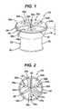
- FIG. 6is a perspective view of one of the discrete housing portions of the surgical access device of FIG. 1 ;
- FIG. 7is a side, cross-sectional view of the discrete housing portion of FIG. 6 ;
- FIG. 8is an exploded view of one embodiment of a sealing element
- FIG. 9is an exploded view of another embodiment of a sealing element
- FIG. 10is a perspective view of one embodiment of a discrete housing portion
- FIG. 11is an exploded view of the discrete housing portion of FIG. 10 ;
- FIG. 12is a perspective, cross-sectional view of one embodiment of a surgical access device including a plurality of the discrete housing portions of FIG. 10 ;
- FIG. 13is a top view of another embodiment of a surgical access device including a plurality of discrete housing portions
- FIG. 14is a perspective view of one embodiment of a surgical access device including a plurality of discrete housing portions and a rigid retractor;
- FIG. 15is a perspective view of one embodiment of a discrete housing portion having an insufflation port extending therefrom;
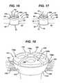
- FIG. 16is a perspective, partially cross-sectional view of the surgical access device of FIG. 1 positioned within a tissue opening and having a surgical instrument inserted through one of the discrete housing portions;
- FIG. 17is a perspective, partially cross-sectional view of the surgical access device of FIG. 16 with the discrete housing portion having the instrument inserted therethrough moved to a different position relative to the other discrete housing portions;
- FIG. 18is a perspective, partially cross-sectional view of another embodiment of a surgical access device having a plurality of discrete housing portions, the surgical access device being positioned within a tissue opening.
- a surgical access devicecan be configured to be positioned in tissue to enable access through a working channel of the surgical access device to a body cavity underlying the tissue.
- the surgical access devicecan include a flexible member and a plurality of discrete housing portions disposed in at least a proximal portion of an outer housing. Each of the discrete housing portions can be surrounded by the flexible member within the outer housing and be configured to move independently therein relative to one another and to the outer housing.
- the flexible membercan be configured to act as a barrier between the discrete housing portions such that when one of the discrete housing portions moves, the flexible member can flex to allow the other discrete housing portions to remain in a substantially fixed position relative to the outer housing. In this way, a surgical instrument inserted through one of the discrete housing portions and into a body cavity can be desirably positioned without disturbing positions of any other instruments inserted through any of the other discrete housing portions.
- the various surgical access devicescan include a wound protector, cannula, or other member for forming a pathway through tissue (hereinafter generally referred to as a retractor).
- the retractorcan extend from the housing and it can be configured to be positioned within an opening in a patient's body, such as the umbilicus.
- the sealing portscan each define working channels extending through the housing and aligned with the retractor.
- Any and all of the surgical access devices described hereincan also include various other features, such as one or more ventilation ports to allow evacuation of smoke during procedures that utilize cautery, and/or one or more insufflation ports through which the surgeon can insufflate the abdomen to cause pneumoperitenium, as described by way of non-limiting example in U.S. Patent Application No.
- the insufflation portcan be located anywhere on the device, can have any size, and can accept a leur lock or a needle, as will be appreciated by those skilled in the art.
- any and all embodiments of a surgical access devicecan also include one or more retractor protectors or safety shields positioned through, in, and around any of the components and/or tissue to protect the components against puncture or tear by surgical instruments being inserted through the device.
- any and all embodiments of a surgical access devicecan include engagement and release mechanisms that allow certain components of the surgical access device to be removable as needed.
- the surgical access devices disclosed hereincan provide access to a patient's body cavity.
- the retractorcan be positionable within an opening in a patient's body such that a distal portion of the retractor extends into a patient's body cavity and a proximal portion configured to couple to the housing is positioned adjacent to the patient's skin on an exterior of the patient's body.
- a lumen in the retractorcan form a pathway through the opening in a patient's body so that surgical instruments can be inserted from outside the body to an interior body cavity.
- the elasticity of the skin of the patientcan assist in the retention of the retractor in the body opening or incision made in the body.
- the retractorcan be placed in any opening within a patient's body, whether a natural orifice or an opening made by an incision.
- the retractorcan be substantially flexible so that it can easily be maneuvered into and within tissue as needed.
- the retractorcan be substantially rigid or substantially semi-rigid.
- the retractorcan be formed of any suitable material known in the art, e.g., silicone, urethane, thermoplastic elastomer, and rubber.
- Non-limiting examples of retractorsinclude a Hakko® Wound Protector available from Hakko Medical Co. of Tokyo, Japan, an Alexis® Wound Protector available from Applied Medical Resources Corp.
- a retractoris not positioned outside a patient's body. Rather, a proximal portion of a surgical access the retractor can be positionable within an opening in a patient's body such that a proximal end of the device is positioned adjacent to the patient's skin on an exterior of the patient's body and a retractor distally extending from the proximal portion of the device is positioned within the opening and/or within a patient's body cavity.
- most surgical access devicestypically include at least one seal disposed therein to prevent air and/or gas from escaping when surgical instruments are inserted therethrough.
- the surgical access devicecan include at least one instrument seal that forms a seal around an instrument disposed therethrough, but otherwise does not form a seal when no instrument is disposed therethrough, at least one channel seal or zero-closure seal that seals the working channel created by the sealing port when no instrument is disposed therethrough, or a combination instrument seal and channel seal that is effective to both form a seal around an instrument disposed therethrough and to form a seal in the working channel when no instrument is disposed therethrough.
- seals known in the artcan be used including, e.g., duckbill seals, cone seals, flapper valves, gel seals, diaphragm seals, lip seals, iris seals, etc.
- sealscan also appreciate that any combination of seals can be included in any of the embodiments described herein, whether or not the seal combinations are specifically discussed in the corresponding description of a particular embodiment.
- a surgical access device 10having a proximal portion 16 including a housing 12 , and a distal portion 20 including a retractor 18 having a pathway, passageway, inner lumen, or working channel 18 a extending therethrough.
- the housing 12can be configured to have one or more surgical instruments inserted therethrough and can include an outer housing 14 having a plurality of discrete housing portions 24 a , 24 b , 24 c , generally referred to as “housing portions,” disposed therein that each define at least one sealing or access port.
- first, second, and third housing portions 24 a , 24 b , 24 care disposed in the outer housing 14 .
- each of the housing portions 24 a , 24 b , 24 ccan seat any number of sealing ports
- the first, second, and third housing portions 24 a , 24 b , 24 chave first, second, and third sealing ports 22 a , 22 b , 22 c , respectively, that extend through the outer housing 14 and that respectively seat first, second, and third sealing elements, as discussed further below.
- a flexible member 26 disposed in the outer housing 14can couple together the housing portions 24 a , 24 b , 24 c and be configured to allow each of the housing portions 24 a , 24 b , 24 c to freely, independently move relative to one another, as discussed further below.
- the housing 12can be configured to releasably or fixedly mate to the retractor 18 .
- the retractor 18can thus be configured to distally extend from the housing 12 and to provide a pathway through tissue into a body cavity.
- the retractor 18is flexible and has a proximal flange 28 and a distal flange 30 with an inner elongate portion 32 extending therebetween.
- the housing 12 and the retractor 18can each have various sizes, shapes, and configurations, as discussed further below.
- the device 10can include any number of other elements, such as an intermediate locking ring (not shown) disposed between the housing 12 and the retractor 18 and configured to facilitate releasable attachment of the housing 12 and the retractor 18 , and such as an o-ring (not shown) configured to provide a seal between two or more elements.
- an intermediate locking ring(not shown) disposed between the housing 12 and the retractor 18 and configured to facilitate releasable attachment of the housing 12 and the retractor 18
- an o-ring(not shown) configured to provide a seal between two or more elements.
- the device 10can also include an insufflation port (not shown) in the outer housing 14 , although a person skilled in the art will appreciate that the insufflation port can be located elsewhere in the housing 12 or in other locations, e.g., in the flexible member 26 , in one of the housing portions 24 a , 24 b , 24 c , etc.
- the device 10can include any number of insufflation ports and that an insufflation port can have a variety of configurations.
- the insufflation portcan be configured to pass an insufflation fluid through a flexible insufflation tube and into an insufflation orifice of the insufflation port where the fluid can flow through a pathway, inner lumen, passageway, or working channel 14 a defined by the outer housing 14 , into the retractor's pathway 18 a , and into a body cavity.
- a stopcockcan control fluid flow through the insufflation tube.
- the retractor 18can have various sizes, shapes, and configurations. Although the retractor 18 in the illustrated embodiment is flexible, as mentioned above the retractor 18 can be rigid. As also mentioned above, the retractor 18 can extend distally from the proximal portion 16 of the device 10 , and it can be configured to be positioned in an opening formed in tissue.
- the inner elongate portion 32 of the retractor 18can, as shown in FIG. 3 , have a diameter less than a diameter of the proximal and distal flanges 28 , 30 , which can have the same diameter or different diameters from one another.
- the proximal flange 28can be configured to be seated within the outer housing 14 , such as on a distal flange (not shown) extending radially inward at a distal end of the outer housing 14 , and be optionally attached thereto using an adhesive, sealant, complementary threads, or any other attachment mechanism, as will be appreciated by a person skilled in the art.
- a proximal o-ring(not shown) can be optionally positioned within the proximal flange 28 to help provide structural support to the retractor 18 within the outer housing 14 .
- a distal o-ring(not shown) can optionally be positioned within the distal flange 30 to provide structural support to the retractor 18 within a patient's body.
- the proximal and distal o-ringscan be substantially flexible or substantially rigid as needed for use in a particular application.
- the housing 12 of the surgical access device 10can have a variety of sizes, shapes, and configurations.
- the housing 12 in the illustrated embodimentis non-removably attached to the retractor 18 and is not rotatable or otherwise movable relative thereto, except for flexing of the flexible member 26 and movement of the housing portions 24 a , 24 b , 24 c as discussed further below.
- the housing 12can be movable relative to the retractor 18 , e.g., the housing 12 can be configured to be releasable from and reattachable to the retractor 18 , the housing 12 can be configured to rotate relative to the retractor 18 , etc.
- Exemplary embodiments of housings releasable from and reattachable to a retractor and/or rotatable relative to a retractorare described in more detail in U.S. patent application Ser. No. 12/399,473 entitled “Methods And Devices For Providing Access Into A Body Cavity,” filed on Mar. 6, 2009, U.S. Patent Application No. 2006/0247673 entitled “Multi-port Laparoscopic Access Device” filed Nov. 2, 2006, U.S. application Ser. No. 12/399,482 entitled “Methods and Devices for Providing Access to a Body Cavity” filed on Mar. 6, 2009, U.S. application Ser. No. 12/242,765 entitled “Surgical Access Device” filed on Sep.
- an engagement and/or release mechanismcan be included to allow the housing 12 to be separated from the retractor 18 , and/or to allow a sealing element to be removed from any of the housing portions 24 a . 24 b . 24 c .
- Any engagement and release mechanism known in the arte.g., a snap-lock mechanism, corresponding threads, etc., can be used to releasably mate two components of the device 10 .
- the engagement and release mechanismcan include a latch mechanism, as described by way of non-limiting example in U.S. application Ser. No. 12/242,765 entitled “Surgical Access Device” filed on Sep. 30, 2008, which is hereby incorporated by reference in its entirety.
- the engagement and release mechanismcan include a bayonet latch mechanism, as described by way of non-limiting example in U.S. application Ser. No. 12/242,765 entitled “Surgical Access Device” filed on Sep. 30, 2008, U.S. application Ser. No. 12/399,482 entitled “Methods and Devices for Providing Access to a Body Cavity” filed on Mar. 6, 2009, U.S. application Ser. No. 12/512,542 entitled “Methods And Devices For Providing Access Into A Body Cavity” filed on Jul. 30, 2009, and U.S. application Ser. No. 12/512,568 entitled “Methods And Devices For Providing Access Into A Body Cavity” filed on Jul. 30, 2009, which are hereby incorporated by reference in their entireties.
- the housing 12can include, as illustrated in FIGS. 1-4 , the outer housing 14 , the flexible member 26 , and the housing portions 24 a , 24 b , 24 c .
- the outer housing 14can include an annular ring, e.g., a substantially rigid cylindrical or circular member, that defines the working channel 14 a extending therethrough between proximal and distal ends 14 p , 14 d of the outer housing 14 .
- the flexible member 26 and the housing portions 24 a , 24 b , 24 ccan be disposed across the proximal end 14 p of the outer housing 14 to define a proximal surface of the housing 12 .
- the flexible member 26 and the housing portions 24 a , 24 b , 24 ccan be configured to be removable from the outer housing 14 as a singular unit as shown in the exploded view of the housing 12 in FIG. 4 , the flexible member 26 and the housing portions 24 a , 24 b , 24 c in the illustrated embodiment are non-removably attached to the outer housing 14 .
- the flexible member 26 and the housing portions 24 a , 24 b , 24 ccan together provide a fluid-tight seal of the outer housing's working channel 14 a .
- one or more seal memberse.g., o-rings (not shown), can be positioned between the outer housing 14 and the flexible member 26 and/or the housing portions 24 a , 24 b , 24 c to help form a seat and seal therebetween.
- the flexible member 26can have a variety of configurations.
- the flexible member 26can be formed of any one or more materials in any combination.
- the materialcan include a flexible, composite material, e.g., a gel, a foam, an elastomer, isoplast (polyurethane), polyisoprene (natural rubber), santoprene (thermoplastic rubber), etc., configured to prevent fluid passage therethrough, to flex upon application of an external force without breaking, tearing, or otherwise allowing fluid to pass therethrough, and to dynamically flex to return to a default or resting position when the external force is removed.
- a flexible, composite materiale.g., a gel, a foam, an elastomer, isoplast (polyurethane), polyisoprene (natural rubber), santoprene (thermoplastic rubber), etc.
- a non-limiting example of a gel materialincludes a combination of an internal low molecular weight chemical species such as mineral oil or other oil, plasticizer, etc. and KratonTM Rubber, e.g., styrene-ethylene/butylene-styrene (S-E/B-S) tri-block polymer, available from Kraton Polymers LLC of Houston, Tex.
- a foam materialcan have a lower elastic modulus than a gel material, e.g., about 10% of the elastic modulus of a gel material.
- any foam materialcan be used, non-limiting examples of a foam material includes KratonTM Rubber, silicone elastomers, polyurethanes, polyolefins such as polypropylene and polyethylene, polyolefin elastomers such as SantopreneTM, e.g., a crosslinked co-polymer of polypropylene and EPDM (ethylene propylene diene M-class) rubber, available from Advanced Elastomer Systems, LP of Akron, Ohio, polyethylene-co-vinyl acetate copolymers, polytetrafluoroethylene (PTFE) in the form of expanded PTFE, etc.
- the flexible material 26can optionally have a protective coating (not shown) on at least a proximal surface thereof to help prevent damage to the flexible material 26 from sharp instruments or other objects.
- the flexible material 26can be configured to allow one or more surgical instruments to be inserted therethrough and to form an instrument seal around the instrument(s) inserted therethrough.
- Exemplary embodiments of a flexible material through which instruments can be insertedare described in more detail in U.S. patent application Ser. No. 12/479,293 entitled “Methods And Devices For Providing Access Through Tissue To A Surgical Site”, filed on Jun. 5, 2009, which is hereby incorporated by reference in its entirety.
- the flexible material 26can be configured to have the housing portions 24 a , 24 b , 24 c disposed, seated, or suspended therein and to form a seat and seal between the housing 12 and a distal portion of the device 10 , e.g., the retractor 18 .
- each of the housing portions 24 a , 24 b , 24 ccan be disposed in the flexible material 26 with the flexible member 26 acting as a hinge and providing a barrier between each of the housing portions 24 a , 24 b , 24 c such that none of the housing portions 24 a , 24 b , 24 c directly contact one another.
- the housing portions 24 a , 24 b , 24 ccan be disposed in the outer housing's working channel 14 a and define channels 25 therebetween in which the flexible material 26 can be disposed.
- the flexible material 26can be disposed in the channels 25 defined by and extending between the housing portions 24 a , 24 b , 24 c and the outer housing 14 .
- the channels 25can, as shown in the illustrated embodiment, extend between each of the housing portions 24 a , 24 b , 24 c and around an inner perimeter or circumference of the outer housing 14 such that the flexible member 26 is contained within the outer housing 14 and surrounds each of the housing portions 24 a , 24 b , 24 c to prevent any of the housing portions 24 a , 24 b , 24 c from being in direct contact with the outer housing 14 .
- the housing portions 24 a , 24 b , 24 ccan freely and selectively move in any direction relative to one another and to the outer housing 14 , as discussed further below.
- the flexible material 26can be configured to maintain a seat and seal between the housing 12 and the retractor 18 when any one or more of the housing portions 24 a , 24 b , 24 c so move, e.g., maintain a substantially closed space between the moving one or more housing portions 24 a , 24 b , 24 c and the flexible member 26 .
- the housing portions 24 a , 24 b , 24 ccan each have any size, shape, and configuration, as can the sealing ports 22 a , 22 b , 22 c .
- the housing portions 24 a , 24 b , 24 cinclude discrete, separate, isolated, or non-contacting units each being sealed relative to one another such that a surgical instrument inserted through one housing portion does not disturb channel and/or instrument seals provided by the flexible member 26 and by the other housing portions.
- the housing portions 24 a , 24 b , 24 ccan be disposed in the flexible member 26 such that proximal surfaces 24 p of the housing portions 24 a , 24 b , 24 c can extend above or proximally beyond a proximal surface 26 p of the flexible member by a distance or height h. Positioning at least a portion of the housing portions 24 a , 24 b , 24 c above the flexible member 26 can help improve accessibility of the housing portions 24 a , 24 b , 24 c when the device 10 is positioned in tissue.
- proximal surfaces 24 p of any one or more of the housing portions 24 a , 24 b , 24 ccan be flush or co-planar with the proximal surface 26 p of the flexible member 26 and/or be recessed within the flexible member 26 .
- the housing portions 24 a , 24 b , 24 ccan be radially arranged around a central axis or center point of the housing 12 , e.g., a central axis or center point 40 of the outer housing 14 , such that each of the sealing ports 22 a , 22 b , 22 c can have a central axis or center point 42 a , 42 b , 42 c that differs from each other.
- Each of the sealing ports 22 a , 22 b , 22 ccan have center points 42 a , 42 b , 42 c selectively positioned any distance from the center point 40 of the outer housing 14 .
- the center points 42 a , 42 b , 42 c of the sealing ports 22 a , 22 b , 22 ccan each be located a same first distance D 1 from the outer housing's center point 40 .
- each of the housing portions 24 a , 24 b , 24 ccan be movably disposed in the outer housing's working channel 14 a and be configured to move relative to the outer housing 14 , to one another, and to the retractor 18 .
- any one of the housing portions 24 a , 24 b , 24 ccan be selectively, laterally moved in any one or more direction toward and/or away from any of the other housing portions 24 a , 24 b , 24 c .
- Such a configurationcan help facilitate instrument positioning in a body cavity to which the device 10 provides access and can help prevent jostling or otherwise moving a previously-positioned instrument inserted through another one of the housing portions 24 a , 24 b , 24 c .
- the flexible member 26surrounds each of the housing portions 24 a , 24 b , 24 c , the housing portions 24 a , 24 b , 24 c are each free to move in any direction 360° therearound.
- the first housing portion 24 acan be moved relative to the second and third housing portions 24 b , 24 c and the outer housing 14 from a first position, shown with the first housing portion 24 a in solid outline, to a second position, shown with the first housing portion 24 b in dotted outline, relative to the second and third housing portions 24 b , 24 c and the outer housing 14 .
- the flexible member 26flexes, e.g., stretches and compresses, in the channels 25 , thereby allowing movement of the first housing portion 24 a while holding the other housing portions 24 b , 24 c in substantially fixed positions relative to the first housing portion 24 a and the outer housing 14 . Maintaining the second and third housing portions 24 b , 24 c in substantially fixed positions while the first housing portion 24 a moves and when the first housing portion 24 a is in the second, non-default position can allow any instruments inserted through the second and/or third housing portions 24 b , 24 c to remain in desired positions.
- first housing portion 24 aFrom the first position to the second position the first housing portion 24 a has been moved radially inward in two directions such that the first housing portion 24 a has moved a first lateral distance L 1 in a downward direction and a second lateral distance L 2 in a right direction.
- first lateral distance L 1in a downward direction
- second lateral distance L 2in a right direction.
- housing portions 24 a , 24 b , 24 ccan each move in any lateral direction, i.e., in a plane transverse to a longitudinal axis of the device 10 , e.g., the central axis of the outer housing 40 .
- the first housing portion's center point 42 ais the first distance D 1 from the outer housing's center point 40 with the first housing portion 24 a in the first position and changes to a second distance D 2 with the first housing portion 24 a in the second position.
- the second distance D 2is smaller than the first distance D 1 in the illustrated embodiment, but the second distance D 2 can be greater than the first distance D 1 .
- the first housing portion 24 acan move from the first position to another position in an orbit around the outer housing's center point 40 such that the first distance D 1 remains constant. As mentioned above, although the first housing portion 24 a is shown in FIG.
- the first housing portion 24 acan be moved in any direction.
- FIG. 5illustrates the first housing portion 24 a moving between only two positions, the first housing portion 24 a , as well as any or all of the other housing portions 24 b , 24 c , can be repositioned any number of times and in any number of directions.
- the housing portions 24 a , 24 b , 24 ccan simultaneously and/or sequentially move relative to each other and the outer housing 14 .
- the housing portions 24 a , 24 b , 24 care configured to only be laterally movable, e.g., movable in a plane of the housing's proximal surface
- the housing portions 24 a , 24 b , 24 ccan be configured to be additionally or alternatively longitudinally movable relative to the outer housing 14 .
- the housing portions 24 a , 24 b , 24 c of FIGS. 1-4can horizontally move relative to the outer housing 14 and the retractor 18 but cannot vertically move relative to the outer housing 14 and the retractor 18 .
- housing portions 24 a , 24 b , 24 ccan have negligible vertical movement in the illustrated embodiment but nevertheless generally have substantially fixed vertical positions relative to the outer housing 14 . If vertical repositioning of a surgical instrument inserted through one of the housing portions 24 a , 24 b , 24 c is desired, the instrument can be vertically moved relative to the one of the housing portions 24 a , 24 b , 24 c.
- the housing portions 24 a , 24 b , 24 ccan be configured to be movable relative to the outer housing 14 and the retractor 18 through application of an external force with or without any instruments inserted through any of their respective sealing ports 22 a , 22 b , 22 c , e.g., by being manually moved by hand
- the housing portions 24 a , 24 b , 24 ccan also be configured to move relative to the outer housing 14 and the retractor 18 in response to motion of at least one instrument inserted through one of the sealing ports 22 a , 22 b , 22 c .
- the moved one of the housing portions 24 a , 24 b , 24 ccan return to its default position.
- the housing portions 24 a , 24 b , 24 ccan each be wedge-shaped and include first, second, and third cut-outs or openings 38 a , 38 b , 38 c that define the first, second, and third sealing ports 22 a , 22 b , 22 c , respectively.
- the housing portions 24 a , 24 b , 24 ccan have other shapes, e.g., cylindrical.
- a proximal surface of a housing portioncan be substantially flat with the housing portion's port opening being formed in a same plane with each other, either co-planar parallel to the proximal surface or recessed in the housing portion.
- a proximal surface 24 p of the first housing portion 24 acan be non-planar with at least one raised portion proximally displaced from and substantially parallel to a plane of the proximal surface 24 p , or, as shown in FIGS. 6 and 7 illustrating the first housing portion 24 a , with at least one recessed portion 24 r extending in a plane distally displaced from and substantially parallel to a plane of the proximal surface 24 p .
- the housing portion's one or more recessed portions and one or more raised portionscan help compensate for sealing elements of different lengths to help prevent distal seal element openings of each of the sealing elements from contacting an interior of the retractor 18 , at least when the surgical access device 10 is in a default position, e.g., as illustrated in FIGS. 1 and 2 , and at least when the device 10 is not positioned in tissue and has no surgical instruments inserted therethrough.
- the openings 38 a , 38 b , 38 ccan extend through their respective housing portions 24 a , 24 b , 24 c such that surgical instruments can be inserted into the openings 38 a , 38 b , 38 c and into the retractor 18 .
- each housing portion 24 a , 24 b , 24 cincludes one opening 38 a , 38 b , 38 c
- a housing portioncan include any number of openings arranged in any way, with each opening having at least one associated sealing port.
- the openings 38 a , 38 b , 38 ccan also have any combination of sizes and shapes.
- the openings 38 a , 38 b , 38 ccan each have a shape corresponding to a shape of the sealing element seated therein, which in the illustrated embodiment is substantially circular.
- the sealing ports 22 a , 22 b , 22 ccan have different sizes, e.g., 3 mm, 5 mm, 15 mm, 12 mm, etc., in the illustrated embodiment, the openings 38 a , 38 b , 38 c have equal sizes and have equal-sized sealing ports 22 a , 22 b , 22 c seated therein.
- each of the sealing ports 22 a , 22 b , 22 ccan each have a central axis, e.g., a longitudinal axis through their respective center points 42 a , 42 b , 42 c , that extends substantially perpendicular to a plane of the proximal surface 14 p of the outer housing 14 and that is substantially parallel to a longitudinal axis of the retractor 18 .
- a central axise.g., a longitudinal axis through their respective center points 42 a , 42 b , 42 c , that extends substantially perpendicular to a plane of the proximal surface 14 p of the outer housing 14 and that is substantially parallel to a longitudinal axis of the retractor 18 .
- the sealing ports 22 a , 22 b , 22 ccan each be in a fixed position relative to their respective housing portions 24 a , 24 b , 24 c as in the illustrated embodiment such that center axes of the sealing ports 22 a , 22 b , 22 c are substantially perpendicular to proximal surfaces 24 p of their respective housing portions 24 a , 24 b , 24 c , but any one or more components in each sealing port can be angled relative to its respective housing portion 24 a , 24 b , 24 c and/or rotatable or otherwise movable relative to its respective housing portion 24 a , 24 b , 24 c and/or other portion(s) of the housing 12 .
- each of the sealing ports 22 a , 22 b , 22 ccan include a sealing element providing an instrument seal and/or a channel or zero-closure seal disposed therein.
- the sealing elements disposed in each sealing port 22 a , 22 b , 22 ccan be attached or mated to their respective housing portions 24 a , 24 b , 24 c using any attachment or mating mechanism known in the art.
- each sealing elementis engaged by an interference fit between upper and lower portions (not shown) of its respective housing portion 24 a , 24 b , 24 c .
- housing portions 24 a , 24 b , 24 ccan each be a singular member or can have multiple portions mated together in any way
- pinscan proximally extending from an outer perimeter of a housing portion's lower portion and be configured to extend into corresponding bores formed in a circumferential wall of the housing portion's upper portion to mate the upper and lower portions together.
- the sealing elementscan have a variety of sizes, shapes, and configurations. As shown in the illustrated embodiment in FIGS. 4 , 6 , 7 , and 8 , the sealing elements of the housing portions 24 a , 24 b , 24 c each include a distal duckbill seal 44 that provides a channel seal, and a proximal septum seal 46 that provides an instrument seal.
- a protective member 48can be positioned proximal to the septum seal 46 to protect the septum seal 46 from accidental puncture.
- the septum seal 46can optionally include a beveled edge on an interior circumference thereof, which can help facilitate instrument insertion therethrough.
- the protective member 48can have an inner diameter substantially equal to an outer diameter of the beveled circumferential edge, which can help protect the septum seal 46 without floating and without substantially limiting angular movement of instruments inserted therethrough.
- the duckbill seal 44forms a channel or zero-closure seal to seal a working channel of the sealing port when no instrument is disposed therethrough to prevent leakage of insufflation gases delivered through the surgical access device 10 to a body cavity.
- the duckbill seal 44will generally not form a seal around an instrument inserted therethrough.
- the septum seal 46can engage and form a seal around an outer surface of the instrument to thereby prevent the passage of fluids and gas through the seal.
- the center opening of the protective member 48 and the septum seal 46will generally not form a seal in the working channel of sealing port.
- first, seconds and third sealing elements of the first, second, and third housing portions 24 a , 24 b , 24 care identical to one another in the illustrated embodiment, a person skilled in the art will appreciate that the second and third sealing elements can be same as or different from any one or more of the other sealing elements.
- FIG. 9illustrates another exemplary embodiment of a sealing element that can be included in a housing portion.
- This sealing elementincludes a fan seal 50 , a fan seal protector 52 positioned concentric with and proximal to the fan seal 50 , and a bottom ring 54 in which the fan seal 50 can be concentrically seated with the fan seal protector 52 to together form an instrument seal in a sealing port.
- a distal duckbill seal 56can be positioned concentric and distal to the bottom ring 54 , and thus the bottom ring 54 can act as a spacer to separate the fan seal 50 and the duckbill seal 62 .
- the sealing element of FIG. 9can generally be used in a manner similar to the sealing element of FIG. 8 , with an instrument being insertable through a center opening in the fan seal 50 and the fan seal protector 52 and then through the duckbill seal 56 and into a working channel of the retractor 18 when the retractor 18 is coupled to the housing 12 .
- Each of the distal duckbill seals 44 , 56 , the fan seal 50 , the fan seal protector 52 , and the septum seal 46can include a radially-outward extending proximal flange 44 a , 46 a , 50 a , 52 a , 56 a .
- the proximal flanges 44 a , 46 a , 50 a , 52 a , 56 acan each be captured between a proximal surface of the lower portion of a housing portion and an inner distal cylindrical rib or projection formed around each of the openings in the upper portion of the housing portion, thereby seating the sealing elements within their respective port openings in the housing portion.
- FIG. 9includes the bottom ring 54 and the sealing element of FIG. 8 includes the protective member 48 that are also captured between upper and lower portions of a housing portion.
- the upper and lower portions of the housing portions 24 a , 24 b , 24 ccan be sealingly engaged, thereby forming a seal around the sealing ports 22 a , 22 b , 22 c .
- one or more projectionse.g., cylindrical pegs or prongs (not shown), can proximally extend from an inner surface of a housing portion's lower portion and each be inserted into a corresponding cavity (not shown), e.g., a cylindrical bore, formed in an inner surface of the housing portion's upper portion.
- any seale.g., duckbill seals, cone seals, flapper valves, gel seals, diaphragm seals, lip seals, iris seals, non-linear sealing elements such sealing elements with an S-shaped opening, etc., same or different from any other of the other distal seals 44 , 56 can be used and can be aligned in any way relative to their respective housing portions 24 a , 24 b , 24 c and to the outer housing 14 .
- a zero-closure sealcan be configured to form a seal in a working channel when no instrument is disposed therethrough to thus prevent the leakage of insufflation gases delivered through the surgical access device to the body cavity.
- a duckbill sealcan generally have opposed flaps that extend at an angle toward one another in a distal direction and that come together at a distal end to form a seal face. The opposed flaps can be movable relative to one another to allow the seal face to move between a closed position, in which no instrument is disposed therethrough and the seal face seals the working channel of the surgical access device, and an open position in which an instrument is disposed therethrough.
- a duckbill sealcan include various other features, as described in more detail in U.S. application Ser. No.
- the seal face of the duckbill sealcan be in any nonlinear shape or configuration known in the art, for example in an S-shaped configuration, as described in more detail in U.S. Pat. No. 5,330,437, entitled “Self Sealing Flexible Elastomeric Valve and Trocar Assembly for Incorporating Same,” filed Nov. 12, 1993, which is hereby incorporated by reference in its entirety.
- the sealing ports 22 a , 22 b , 22 ccan be configured to be in a fixed position relative to their respective housing portions 24 a , 24 b , 24 c and to move with their respective housing portions 24 a , 24 b , 24 c relative to the outer housing 14 and the retractor 18 , as discussed further below.
- any one or more of the sealing ports 22 a , 22 b , 22 ccan be configured to be movable relative to any one or more portions of the housing 12 , such as the housing portions 24 a , 24 b , 24 c , the outer housing 14 , or any others of the sealing ports 22 a , 22 b , 22 c.
- the sealing elementscan distally extend from their respective housing portions 24 a , 24 b , 24 c , and from the flexible member 26 , such that at least distal portions of the sealing elements freely extend into the working channel 14 a of the outer housing 14 .
- Such a configurationcan facilitate movement of the housing portions 24 a , 24 b , 24 c and the sealing elements relative to the outer housing 14 and help better position instruments inserted through the housing portions 24 a , 24 b , 24 c .
- one or more of the housing portionscan be configured such that the sealing elements can be contained therein. In an exemplary embodiment illustrated in FIGS.
- a discrete housing portion 24 ′can include a wedge-shaped block having a depth 24 d ′ equal to (as shown) or less than a depth of an outer housing 14 ′′′ in which it is disposed.
- a flexible member 26 ′′′ disposed in the outer housing 14 ′′′ and surrounding multiple ones of the housing portions 24 ′ disposed thereincan fill channels 25 ′′′ defined by the housing portions 24 ′ disposed in a working channel of the outer housing 14 ′′′ such that the outer housing's working channel includes no open space, e.g., is filled by the flexible member 26 ′′′ and the housing portions 24 ′.
- the housing portions 24 ′can each include an upper portion 24 u matable to a lower portion 241 in a fluid-tight mating connection with a sealing element 27 including the duckbill seal 44 , the septum seal 46 , and the protective member 48 of FIG. 8 disposed in an opening 38 ′ defined by the upper and lower portions 24 u , 24 l.
- the device 10can include any number of discrete housing portions.
- the illustrated housing portions 24 a , 24 b , 24 care identical, but a person skilled in the art will appreciate that any one or more of the housing portions 24 a , 24 b , 24 c can be different from any one or more of the device's other housing portions 24 a , 24 b , 24 c .
- FIG. 1A block diagram illustrating an exemplary computing device 10 .
- FIG. 13illustrates an exemplary embodiment of a surgical access device 10 ′ including three discrete wedge-shaped housing portions 24 a ′, 24 b ′, 24 c ′ in which two of the housing portions 24 a ′, 24 b ′ have sealing ports 22 a ′, 22 b ′ of a first size, e.g., 7 mm, and the other housing portion 24 c ′ has a second, smaller size, e.g., 3 mm.
- Providing different sealing port sizes 22 a ′, 22 b ′, 22 c ′can help facilitate insertion of differently sized surgical instruments through the device 10 ′ and effectively seal the instruments inserted therethrough.
- the device 10 ′also includes an insufflation port 34 ′ extending from a flexible member 26 ′ disposed between the housing portions 24 a ′, 24 b ′, 24 c ′.
- FIG. 14illustrates another exemplary embodiment of a surgical access device 10 ′′ including four discrete wedge-shaped housing portions 24 a ′′, 24 b ′′, 24 c ′′, 24 d ′′ and having an insufflation port 34 ′′ extending from a sidewall of an outer housing 14 ′′ in which the housing portions 24 a ′′, 24 b ′′, 24 c ′′, 24 d ′′ are disposed.
- the insufflation port 34 ′′can be configured to couple to an insufflation tube 36 ′′.
- FIG. 14also illustrates an exemplary embodiment of a rigid retractor 18 ′′ distally extending from the outer housing 14 ′′ and having a distally-tapering truncated cone shape.
- FIG. 15illustrates an exemplary embodiment of a discrete housing portion 24 ′′′ having an insufflation port 34 ′′′ extending proximally therefrom, although the insufflation port 34 ′′′ can extend therefrom in any direction.
- a retractor protector or safety shieldcan optionally be included to reduce the risk of tearing or puncture by a surgical instrument.
- a retractor protectorcan be configured to extend at least partially into the inner lumen 18 a of the retractor 18 to thereby provide a protective lining as surgical instruments are inserted through the device 10 .
- the retractor protectorcan have a length corresponding to a length of the retractor 18 , but can also have a length less than or considerably longer than the length of the retractor 18 depending on a specific application.
- the retractor protectorcan be mated to the device's proximal portion 16 , e.g., the housing 12 , using any attachment mechanism, e.g., adhesive, screws, press fit, etc., as will be appreciated by a person skilled in the art.
- the retractor protectorcan be of a material that is relatively smooth and with a low coefficient of friction to allow ease of passage of instruments, but resistant to tearing and puncture.
- the retractor protectorcan be formed of silicone, urethane, thermoplastic elastomer, rubber, polyolefins, polyesters, nylons, fluoropolymers, and any other suitable materials known in the art.
- the retractor protectorcan generally provide a liner for a retractor or tissue and can be detachable from a surgical access device so it can be used as needed in a particular procedure.
- a retractor protectorcan include a plurality of layers, or a retractor protector can be a singular member. Exemplary embodiments of retractor protectors are described in more detail in U.S. patent application Ser. No. 12/399,625 entitled “Methods And Devices For Providing Access Into A Body Cavity,” filed on Mar. 6, 2009, U.S. Patent Application No. 2006/0247673 entitled “Multi-port Laparoscopic Access Device” filed Nov. 2, 2006, U.S. application Ser. No.
- one or more surgical instrumentscan be inserted into a body cavity through the surgical access device 10 , which can help optimally position the surgical instruments relative to the body cavity through movement of the housing portions 24 a , 24 b , 24 c relative to one another, to the outer housing 14 , and to the retractor 18 .
- the device 10can be positioned within tissue to provide access to a body cavity underlying the tissue in a variety of ways. In an exemplary embodiment, illustrated in FIGS. 16 and 17 , the device 10 can be positioned in tissue 58 fully assembled in the device's default position, shown in FIGS. 1 and 2 . In another embodiment, the device 10 can be positioned partially assembled in the tissue 58 and be fully assembled with a portion of the device 10 positioned in the tissue 58 .
- the retractor 18can be positioned within an opening or incision 60 formed in the tissue 58 (generally referred to as an “opening”), e.g., in the umbilicus, with the proximal and distal flanges 28 , 30 of the retractor 18 positioned on opposed sides of the tissue 58 .
- the inner elongate portion 32 of the retractor 18can thereby be positioned within the tissue 58 with the working channel 18 a of the retractor 18 extending through the tissue 58 to provide a path of access to a body cavity 62 underlying the tissue 58 .
- the tissue opening 60can have any shape and size, e.g., a linear cut having a longitudinal length in a range of about 15 to 35 mm and extending through a layer of tissue having a depth of less than about 70 mm.
- the retractor 18can be positioned within the tissue opening 60 in a variety of ways. In an exemplary embodiment, the retractor 18 can be positioned in the opening 60 by hand. In another exemplary embodiment, the retractor 18 can be positioned in the opening 60 using an inserter tool (not shown). Exemplary embodiments of hand-insertion and of an inserter tool are described in more detail in previously mentioned U.S. application Ser. No. 12/512,542 entitled “Methods And Devices For Providing Access Into A Body Cavity” filed on Jul. 30, 2009, and U.S. application Ser. No. 12/512,568 entitled “Methods And Devices For Providing Access Into A Body Cavity” filed on Jul. 30, 2009.
- the housing 12can be positioned above a proximal surface 58 p of the tissue 58 such that a distal surface of the housing 12 , e.g., a distal surface of the outer housing 14 , can abut the tissue's proximal surface 58 p .
- a housing 112 of a surgical access device 100can be at least partially disposed in an opening 160 in tissue 158 , as shown in an exemplary embodiment in FIG. 18 , where a sidewall 115 of an outer housing 114 can be positioned fully or partially in contact with inner walls 161 of the tissue opening 160 .
- the housing portions 124can extend above a proximal surface 158 p of the tissue 158 , thereby facilitating access to housing portions 124 despite the housing 112 being disposed at least partially within the tissue opening 160 .
- Such a low profile device 100can reduce interference with other aspects of the surgical procedure, such as insufflation, visualization inside and outside the patient, etc.
- the surgical access devicecan optionally include a retractor extending distally from the housing.
- one or more surgical instrumentscan be inserted therethrough and into the body cavity 62 where the instruments can help perform any type of surgical procedure.
- insufflationcan be provided using through an insufflation port.
- an instrument 64can be inserted through the first housing portion 24 a in an initial position with the first housing portion 24 a in a first position relative to the outer housing 14 and the other housing portions 24 b , 24 c .
- the instrument 64can be moved from the initial position, shown in FIG. 16 , to a working position, shown in FIG.
- the instrument 64can have any initial and working positions and that the instrument 64 inserted through the first housing portion 24 a can be moved any number of times during a surgical procedure.
- the surgical instrument 64 shown in FIGS. 16 and 17is a grasper having a pair of distal movable jaws, a person skilled in the art will appreciate that any surgical instrument can be inserted through the device 10 .
- the instrument 64is illustrated as being inserted through the first housing portion 24 a , instruments can be simultaneously and/or sequentially inserted through any of the housing portions 24 a , 24 b , 24 c.
- the housing 12is removable from the retractor 18 , at any point before, during, or after a surgical procedure, the housing 12 in full or part can be released from the retractor 18 , and the retractor 18 can be removed from the tissue 58 .
- the working channel 18 a of the retractor 18can provide access to the body cavity 62 underlying the tissue 58 .
- One or more surgical instrumentscan be advanced through the working channel 18 a , such as a waste removal bag configured to hold waste material, e.g., dissected tissue, excess fluid, etc., from the body cavity 62 .
- the bagcan be introduced into the body cavity 62 through the retractor's working channel 18 a or other access port.
- a person skilled in the artwill appreciate that one or more surgical instruments can be advanced through the retractor's working channel 18 a before and/or after the housing 12 has been attached to the retractor 18 .
- a surgical drapecan optionally be placed over the retractor 18 and the tissue opening 60 during removal of the retractor 18 to help reduce dispersion of bodily fluid outside the surgical space.
- an exemplary embodiment of a surgical access device kitcan include multiple housings with one or more retractors. Each housing can have different sealing port configurations including different types and numbers of sealing elements, etc. as needed in particular application.
- an exemplary embodiment of a surgical access device kitcan include multiple modular stopcocks, e.g., an insufflation/vent three-way version, a twist to activate version, a spring loaded version, etc.
- the methods and devicescan be used in almost any part of a human or animal body and in various other types of surgical procedures.
- the devices and methods disclosed hereincan be used in the thoracic cavity, pelvic cavity, cranial cavity and/or any of the body's natural orifices and can be used in endoscopic procedures and/or in open surgical procedures.
- any of the embodiments described hereincan be used in performing a sleeve gastrectomy and/or a gastroplasty, as described in U.S. application Ser. No. 12/242,765 entitled “Surgical Access Device” filed on Sep. 30, 2008; U.S. application Ser. No. 12/242,711 entitled “Surgical Access Device with Protective Element” filed on Sep. 30, 2008; U.S. application Ser. No. 12/242,721 entitled “Multiple Port Surgical Access Device” filed on Sep. 30, 2008; U.S. application Ser. No. 12/242,726 entitled “Variable Surgical Access Device” filed on Sep.
- the devices disclosed hereincan be designed to be disposed of after a single use, or they can be designed to be used multiple times. In either case, however, the device can be reconditioned for reuse after at least one use. Reconditioning can include any combination of the steps of disassembly of the device, followed by cleaning or replacement of particular pieces, and subsequent reassembly.
- the devicecan be disassembled, and any number of the particular pieces or parts of the device can be selectively replaced or removed in any combination, e.g., a housing, a retractor, etc.
- the devicecan be reassembled for subsequent use either at a reconditioning facility, or by a surgical team immediately prior to a surgical procedure.
- reconditioning of a devicecan utilize a variety of techniques for disassembly, cleaning/replacement, and reassembly. Use of such techniques, and the resulting reconditioned device, are all within the scope of the present application.
- the invention described hereinwill be processed before surgery.
- a new or used instrumentis obtained and if necessary cleaned.
- the instrumentcan then be sterilized.
- the instrumentis placed in a closed and sealed container, such as a plastic or TYVEK bag.
- the container and instrumentare then placed in a field of radiation that can penetrate the container, such as gamma radiation, x-rays, or high-energy electrons.
- the radiationkills bacteria on the instrument and in the container.
- the sterilized instrumentcan then be stored in the sterile container.
- the sealed containerkeeps the instrument sterile until it is opened in the medical facility.
- deviceis sterilized. This can be done by any number of ways known to those skilled in the art including beta or gamma radiation, ethylene oxide, steam, and a liquid bath (e.g., cold soak).
Landscapes
- Health & Medical Sciences (AREA)
- Surgery (AREA)
- Life Sciences & Earth Sciences (AREA)
- Biomedical Technology (AREA)
- Nuclear Medicine, Radiotherapy & Molecular Imaging (AREA)
- Engineering & Computer Science (AREA)
- Pathology (AREA)
- Heart & Thoracic Surgery (AREA)
- Medical Informatics (AREA)
- Molecular Biology (AREA)
- Animal Behavior & Ethology (AREA)
- General Health & Medical Sciences (AREA)
- Public Health (AREA)
- Veterinary Medicine (AREA)
- Surgical Instruments (AREA)
Abstract
Description
Claims (16)
Priority Applications (2)
| Application Number | Priority Date | Filing Date | Title |
|---|---|---|---|
| US12/623,018US8376938B2 (en) | 2009-11-20 | 2009-11-20 | Discrete flexion head for single port device |
| PCT/US2010/055262WO2011062768A1 (en) | 2009-11-20 | 2010-11-03 | Discrete flexion head for single port device |
Applications Claiming Priority (1)
| Application Number | Priority Date | Filing Date | Title |
|---|---|---|---|
| US12/623,018US8376938B2 (en) | 2009-11-20 | 2009-11-20 | Discrete flexion head for single port device |
Publications (2)
| Publication Number | Publication Date |
|---|---|
| US20110124967A1 US20110124967A1 (en) | 2011-05-26 |
| US8376938B2true US8376938B2 (en) | 2013-02-19 |
Family
ID=43598350
Family Applications (1)
| Application Number | Title | Priority Date | Filing Date |
|---|---|---|---|
| US12/623,018Active2031-04-14US8376938B2 (en) | 2009-11-20 | 2009-11-20 | Discrete flexion head for single port device |
Country Status (2)
| Country | Link |
|---|---|
| US (1) | US8376938B2 (en) |
| WO (1) | WO2011062768A1 (en) |
Cited By (10)
| Publication number | Priority date | Publication date | Assignee | Title |
|---|---|---|---|---|
| US20100298774A1 (en)* | 2009-05-19 | 2010-11-25 | Igov Igor | Methods and devices for laparoscopic surgery |
| US20110028791A1 (en)* | 2009-07-28 | 2011-02-03 | Marino James F | Arcuate surgical guidance system and methods |
| US20110208007A1 (en)* | 2010-01-20 | 2011-08-25 | EON Surgical Ltd. | Rapid Laparoscopy Exchange System And Method Of Use Thereof |
| US20140135788A1 (en)* | 2010-03-08 | 2014-05-15 | Ashford & St. Peter's Hospitals | Medical device: laparoscopic bag |
| WO2014144233A1 (en)* | 2013-03-15 | 2014-09-18 | Intuitive Surgical Operations, Inc. | Rotating assistant port |
| US20150351737A1 (en)* | 2014-06-05 | 2015-12-10 | Jeffrey Jackson | Multi-chambered cannula |
| US9351761B2 (en)* | 2011-03-25 | 2016-05-31 | Covidien Lp | Access port with integrated flexible sleeve |
| US10052088B2 (en) | 2010-01-20 | 2018-08-21 | EON Surgical Ltd. | System and method of deploying an elongate unit in a body cavity |
| US10390694B2 (en) | 2010-09-19 | 2019-08-27 | Eon Surgical, Ltd. | Micro laparoscopy devices and deployments thereof |
| WO2021086122A1 (en)* | 2019-11-01 | 2021-05-06 | 인제대학교 산학협력단 | Seal port for endoscope |
Families Citing this family (23)
| Publication number | Priority date | Publication date | Assignee | Title |
|---|---|---|---|---|
| US8282546B2 (en) | 2009-12-11 | 2012-10-09 | Ethicon Endo-Surgery, Inc. | Inverted conical expandable retractor with coil spring |
| US8435174B2 (en) | 2009-12-11 | 2013-05-07 | Ethicon Endo-Surgery, Inc. | Methods and devices for accessing a body cavity |
| US8414483B2 (en) | 2009-12-11 | 2013-04-09 | Ethicon Endo-Surgery, Inc. | Methods and devices for providing access into a body cavity |
| US8357088B2 (en) | 2009-12-11 | 2013-01-22 | Ethicon Endo-Surgery, Inc. | Methods and devices for providing access into a body cavity |
| US8231570B2 (en) | 2009-12-11 | 2012-07-31 | Ethicon Endo-Surgery, Inc. | Inverted conical expandable retractor |
| US8409086B2 (en)* | 2009-12-18 | 2013-04-02 | Covidien Lp | Surgical portal with rotating seal |
| US8821390B2 (en) | 2010-04-12 | 2014-09-02 | Covidien Lp | Surgical access method and assembly including sleeve and port |
| US8696557B2 (en) | 2010-12-21 | 2014-04-15 | Covidien Lp | Access assembly including inflatable seal member |
| US9549758B2 (en)* | 2011-03-23 | 2017-01-24 | Covidien Lp | Surgical access assembly with adapter |
| JP6005992B2 (en)* | 2012-05-18 | 2016-10-12 | オリンパス株式会社 | Trokka |
| US10292730B2 (en) | 2013-03-15 | 2019-05-21 | Intuitive Surgical Operations, Inc. | Sealing multiple surgical instruments |
| US9888941B2 (en) | 2013-03-15 | 2018-02-13 | Intuitive Surgical Operations, Inc. | Sealing multiple surgical instruments |
| US10492825B2 (en) | 2013-03-15 | 2019-12-03 | Intuitive Surgical Operations, Inc. | Sealing multiple surgical instruments |
| US20150038797A1 (en)* | 2013-07-31 | 2015-02-05 | Covidien Lp | Instrument or hand access surgical site seal caps |
| US10028731B2 (en) | 2013-11-12 | 2018-07-24 | Genzyme Corporation | Barrier application device |
| US9707011B2 (en) | 2014-11-12 | 2017-07-18 | Covidien Lp | Attachments for use with a surgical access device |
| US10357579B2 (en)* | 2015-10-05 | 2019-07-23 | Texas Medical Group SOPARFI S.a.r.l. | Device port cleaner |
| US10576261B2 (en) | 2015-12-11 | 2020-03-03 | Turnstone Technologies, LLC | Device male port cleaner |
| US10405884B2 (en)* | 2017-10-23 | 2019-09-10 | Conmed Corporation | Devices for performing minimally invasive surgery having rotating multiport access |
| US10463396B2 (en) | 2017-10-23 | 2019-11-05 | Conmed Corporation | Devices for performing minimally invasive surgery having bellows support housing |
| US10413324B2 (en)* | 2017-10-23 | 2019-09-17 | Conmed Corporation | Devices for performing minimally invasive surgery having foam support housing |
| CN108346139A (en)* | 2018-01-09 | 2018-07-31 | 阿里巴巴集团控股有限公司 | A kind of method for screening images and device |
| US20220395293A1 (en)* | 2021-06-11 | 2022-12-15 | Atropos Limited | Transvaginal access devices and methods of use |
Citations (110)
| Publication number | Priority date | Publication date | Assignee | Title |
|---|---|---|---|---|
| US3397699A (en) | 1966-05-05 | 1968-08-20 | Gerald C. Kohl | Retaining catheter having resiliently biased wing flanges |
| US4022191A (en) | 1976-06-04 | 1977-05-10 | Khosrow Jamshidi | Biopsy needle guard and guide |
| US4608977A (en) | 1979-08-29 | 1986-09-02 | Brown Russell A | System using computed tomography as for selective body treatment |
| US4809694A (en) | 1987-05-19 | 1989-03-07 | Ferrara Vincent L | Biopsy guide |
| US5031634A (en) | 1990-01-19 | 1991-07-16 | Beth Israel Hospital Assoc., Inc. | Adjustable biopsy needle-guide device |
| US5053042A (en) | 1990-01-16 | 1991-10-01 | Bidwell Clifford D | Biopsy needle guide for use with CT scanner |
| US5100387A (en) | 1990-07-02 | 1992-03-31 | Ng Raymond C | Disposable universal needle guide apparatus (for amniocentesis) |
| US5201742A (en) | 1991-04-16 | 1993-04-13 | Hasson Harrith M | Support jig for a surgical instrument |
| US5235987A (en) | 1991-02-22 | 1993-08-17 | Dymax Corporation | Needle guide |
| EP0577400A1 (en) | 1992-06-30 | 1994-01-05 | Ethicon, Inc. | Flexible endoscopic surgical port |
| US5312417A (en) | 1992-07-29 | 1994-05-17 | Wilk Peter J | Laparoscopic cannula assembly and associated method |
| US5316014A (en) | 1992-02-07 | 1994-05-31 | Livingston Products, Inc. | Biopsy locator and guide |
| US5320111A (en) | 1992-02-07 | 1994-06-14 | Livingston Products, Inc. | Light beam locator and guide for a biopsy needle |
| US5330437A (en) | 1993-11-12 | 1994-07-19 | Ethicon Endo-Surgery | Self sealing flexible elastomeric valve and trocar assembly for incorporating same |
| US5342315A (en) | 1993-04-12 | 1994-08-30 | Ethicon, Inc. | Trocar seal/protector assemblies |
| US5431676A (en) | 1993-03-05 | 1995-07-11 | Innerdyne Medical, Inc. | Trocar system having expandable port |
| US5494039A (en) | 1993-07-16 | 1996-02-27 | Cryomedical Sciences, Inc. | Biopsy needle insertion guide and method of use in prostate cryosurgery |
| US5569205A (en) | 1994-07-14 | 1996-10-29 | Hart; Charles C. | Multiport trocar |
| WO1996036283A1 (en) | 1995-05-19 | 1996-11-21 | General Surgical Innovations, Inc. | Skin seal with inflatable membrane |
| US5628732A (en) | 1996-01-19 | 1997-05-13 | Ethicon Endo-Surgery, Inc. | Trocar with improved universal seal |
| US5647373A (en) | 1993-11-07 | 1997-07-15 | Ultra-Guide Ltd. | Articulated needle guide for ultrasound imaging and method of using same |
| US5707359A (en) | 1995-11-14 | 1998-01-13 | Bufalini; Bruno | Expanding trocar assembly |
| US5743884A (en)* | 1992-12-17 | 1998-04-28 | Hasson; Harrith M. | Sealing structure for medical instrument |
| US5857999A (en) | 1995-05-05 | 1999-01-12 | Imagyn Medical Technologies, Inc. | Small diameter introducer for laparoscopic instruments |
| US5868673A (en) | 1995-03-28 | 1999-02-09 | Sonometrics Corporation | System for carrying out surgery, biopsy and ablation of a tumor or other physical anomaly |
| US5882340A (en) | 1992-04-15 | 1999-03-16 | Yoon; Inbae | Penetrating instrument having an expandable anchoring portion for triggering protrusion of a safety member and/or retraction of a penetrating member |
| US5911707A (en) | 1997-04-09 | 1999-06-15 | Datascope Investment Corp. | Needle guide |
| US5916175A (en) | 1996-01-26 | 1999-06-29 | Allegiance Corporation | Biopsy needle appliance and inserting guide with adjustable sample length and/or needle cutting stroke |
| US5941889A (en) | 1997-10-14 | 1999-08-24 | Civco Medical Instruments Inc. | Multiple angle disposable needle guide system |
| US5954670A (en) | 1994-10-05 | 1999-09-21 | Baker; Gary H. | Mandrel-guided tandem multiple channel biopsy guide device and method of use |
| US5984930A (en) | 1996-09-30 | 1999-11-16 | George S. Allen | Biopsy guide |
| US6017356A (en) | 1997-09-19 | 2000-01-25 | Ethicon Endo-Surgery Inc. | Method for using a trocar for penetration and skin incision |
| US6048321A (en) | 1997-10-10 | 2000-04-11 | William E. McPherson | Guide assembly for a biopsy device |
| USD422706S (en) | 1997-04-30 | 2000-04-11 | Surgical Navigation Technologies | Biopsy guide tube |
| WO2000041759A1 (en) | 1999-01-13 | 2000-07-20 | A-Med Systems, Inc. | Sealing cannula device |
| US6110182A (en) | 1998-06-22 | 2000-08-29 | Ohio Medical Instruments Company, Inc. | Target socket |
| WO2000062689A1 (en) | 1999-04-21 | 2000-10-26 | Bisgaard Therkel | A trocar with expandable point |
| US6162196A (en)* | 1994-07-14 | 2000-12-19 | Applied Medical Resources Corporation | Multiport access device |
| WO2001008563A2 (en) | 1999-07-30 | 2001-02-08 | Gaya Limited | A surgical access device |
| US6195577B1 (en) | 1998-10-08 | 2001-02-27 | Regents Of The University Of Minnesota | Method and apparatus for positioning a device in a body |
| US6203499B1 (en) | 1998-10-05 | 2001-03-20 | Atl Ultrasound Inc. | Multiple angle needle guide |
| US6216029B1 (en) | 1995-07-16 | 2001-04-10 | Ultraguide Ltd. | Free-hand aiming of a needle guide |
| US6231585B1 (en) | 1997-11-20 | 2001-05-15 | Medivas, Llc | Device for stabilizing a treatment site and method of use |
| US6231565B1 (en) | 1997-06-18 | 2001-05-15 | United States Surgical Corporation | Robotic arm DLUs for performing surgical tasks |
| US6236875B1 (en) | 1994-10-07 | 2001-05-22 | Surgical Navigation Technologies | Surgical navigation systems including reference and localization frames |
| US6245028B1 (en) | 1999-11-24 | 2001-06-12 | Marconi Medical Systems, Inc. | Needle biopsy system |
| US6283942B1 (en) | 1997-12-30 | 2001-09-04 | Volunteers For Medical Engineering | Needle insertion guide apparatus and method |
| WO2002017800A2 (en) | 2000-08-30 | 2002-03-07 | Genzyme Corporation | Dual lumen access port |
| US6361499B1 (en) | 1998-09-16 | 2002-03-26 | Civco Medical Instruments Inc. | Multiple angle needle guide |
| US6379307B1 (en) | 1998-09-16 | 2002-04-30 | Roy Filly | Adjustable needle guide apparatus and method |
| US6400979B1 (en) | 1997-02-20 | 2002-06-04 | Johns Hopkins University | Friction transmission with axial loading and a radiolucent surgical needle driver |
| US6443960B1 (en) | 2000-11-24 | 2002-09-03 | Neorad A/S | Apparatus for light beam guided biopsy |
| US6445943B1 (en) | 1994-09-15 | 2002-09-03 | Visualization Technology, Inc. | Position tracking and imaging system for use in medical applications |
| US6468226B1 (en) | 2000-11-22 | 2002-10-22 | Mcintyre, Iv John J. | Remote tissue biopsy apparatus and associated methods |
| US6475152B1 (en) | 2000-03-13 | 2002-11-05 | Koninklijke Philips Electronics N.V. | Biopsy needle guide for attachment to an ultrasound transducer |
| US6501981B1 (en) | 1999-03-16 | 2002-12-31 | Accuray, Inc. | Apparatus and method for compensating for respiratory and patient motions during treatment |
| US6529765B1 (en) | 1998-04-21 | 2003-03-04 | Neutar L.L.C. | Instrumented and actuated guidance fixture for sterotactic surgery |
| US6535756B1 (en) | 2000-04-07 | 2003-03-18 | Surgical Navigation Technologies, Inc. | Trajectory storage apparatus and method for surgical navigation system |
| US6539121B1 (en) | 1997-02-14 | 2003-03-25 | At&T Corp. | Method and apparatus to prioritize video information during coding and decoding |
| US6546279B1 (en) | 2001-10-12 | 2003-04-08 | University Of Florida | Computer controlled guidance of a biopsy needle |
| US6547782B1 (en) | 1991-06-13 | 2003-04-15 | International Business Machines, Corp. | System and method for augmentation of surgery |
| US6569120B1 (en)* | 1991-10-18 | 2003-05-27 | United States Surgical Corporation | Seal assembly |
| US20030100814A1 (en) | 2001-11-23 | 2003-05-29 | Johann Kindlein | Self controlled image guided device and method for inserting a needle in an animal body for effecting radiation therapy in said body |
| US20030208207A1 (en) | 2002-05-02 | 2003-11-06 | Gmp Surgical Solutions, Inc. | Apparatus for positioning a medical instrument relative to a patient |
| US20030229338A1 (en) | 2000-11-03 | 2003-12-11 | Irion Klaus M. | Device for holding and positioning an endoscopic instrument |
| US6665554B1 (en) | 1998-11-18 | 2003-12-16 | Steve T. Charles | Medical manipulator for use with an imaging device |
| US6687531B1 (en) | 1994-09-15 | 2004-02-03 | Ge Medical Systems Global Technology Company, Llc | Position tracking and imaging system for use in medical applications |
| US6723106B1 (en) | 1998-11-23 | 2004-04-20 | Microdexterity Systems, Inc. | Surgical manipulator |
| US20040082969A1 (en) | 2002-10-23 | 2004-04-29 | Stephen Kerr | Laparoscopic direct vision dissecting port |
| US6731966B1 (en) | 1997-03-04 | 2004-05-04 | Zachary S. Spigelman | Systems and methods for targeting a lesion |
| US6752812B1 (en) | 1997-05-15 | 2004-06-22 | Regent Of The University Of Minnesota | Remote actuation of trajectory guide |
| US6770027B2 (en) | 2001-10-05 | 2004-08-03 | Scimed Life Systems, Inc. | Robotic endoscope with wireless interface |
| US6785572B2 (en) | 2001-11-21 | 2004-08-31 | Koninklijke Philips Electronics, N.V. | Tactile feedback and display in a CT image guided robotic system for interventional procedures |
| US6783524B2 (en) | 2001-04-19 | 2004-08-31 | Intuitive Surgical, Inc. | Robotic surgical tool with ultrasound cauterizing and cutting instrument |
| US20040185453A1 (en) | 2003-03-21 | 2004-09-23 | Joel Myerson | Affinity based methods for separating homologous parental genetic material and uses thereof |
| US6808492B2 (en) | 2002-08-16 | 2004-10-26 | Linvatec Corporation | Endoscopic cannula fixation system |
| US20040230161A1 (en) | 2003-03-21 | 2004-11-18 | Zeiner Mark S. | Trocar seal assembly |
| US20040254426A1 (en) | 2003-04-25 | 2004-12-16 | Thomas Wenchell | Surgical hand access apparatus |
| US20050222582A1 (en) | 2004-04-05 | 2005-10-06 | Thomas Wenchell | Surgical hand access apparatus |
| WO2005097234A2 (en) | 2004-04-05 | 2005-10-20 | Tyco Healthcare Group Lp | Surgical hand access apparatus |
| US7021173B2 (en) | 2002-02-06 | 2006-04-04 | The John Hopkins University | Remote center of motion robotic system and method |
| WO2006057982A2 (en) | 2004-11-24 | 2006-06-01 | Edrich Health Technologies, Inc. | Gel based laparoscopic trocar |
| US20060149137A1 (en) | 2005-01-05 | 2006-07-06 | Applied Medical Resources Corporation | Easily placeable and removable wound retractor |
| US7083626B2 (en) | 2002-10-04 | 2006-08-01 | Applied Medical Resources Corporation | Surgical access device with pendent valve |
| US20060247499A1 (en) | 1998-12-01 | 2006-11-02 | John Butler | Apparatus for inserting a surgical device at least partially through a wond opening |
| US20060247673A1 (en)* | 2005-04-08 | 2006-11-02 | Voegele James W | Multi-port laparoscopic access device |
| US7163525B2 (en)* | 2004-12-17 | 2007-01-16 | Ethicon Endo-Surgery, Inc. | Duckbill seal protector |
| US20070185453A1 (en) | 2003-03-21 | 2007-08-09 | Michael Cropper S | Conical trocar seal |
| US20070260273A1 (en) | 2006-05-08 | 2007-11-08 | Ethicon Endo-Surgery, Inc. | Endoscopic Translumenal Surgical Systems |
| US20070260121A1 (en) | 2006-05-08 | 2007-11-08 | Ethicon Endo-Surgery, Inc. | Endoscopic Translumenal Surgical Systems |
| US20080086080A1 (en) | 2006-10-06 | 2008-04-10 | Surgiquest, Incorporated | Elastically deformable surgical access device having telescoping guide tube |
| US20080086167A1 (en) | 2006-10-06 | 2008-04-10 | Dominick Mastri | Elastically deformable surgical access device |
| US7371227B2 (en)* | 2004-12-17 | 2008-05-13 | Ethicon Endo-Surgery, Inc. | Trocar seal assembly |
| US20080255519A1 (en)* | 2007-03-30 | 2008-10-16 | Pnavel Systems, Inc. | Laparoscopic port assembly |
| US20090005799A1 (en) | 2007-06-29 | 2009-01-01 | Ethicon Endo-Surgery, Inc. | Duckbill seal with fluid drainage feature |
| US20090105659A1 (en) | 2007-10-17 | 2009-04-23 | Tyco Healthcare Group Lp | Anchoring cannula |
| US20090187079A1 (en) | 2008-01-22 | 2009-07-23 | Applied Medical Resources Corporation | Surgical instrument access device |
| US20100081881A1 (en) | 2008-09-30 | 2010-04-01 | Ethicon Endo-Surgery, Inc. | Surgical Access Device with Protective Element |
| US20100081864A1 (en) | 2008-09-30 | 2010-04-01 | Ethicon Endo-Surgery, Inc. | Methods and devices for performing gastrectomies and gastroplasties |
| US20100081880A1 (en)* | 2008-09-30 | 2010-04-01 | Ethicon Endo-Surgery, Inc. | Surgical Access Device |
| US20100081883A1 (en) | 2008-09-30 | 2010-04-01 | Ethicon Endo-Surgery, Inc. | Methods and devices for performing gastroplasties using a multiple port access device |
| US20100081995A1 (en) | 2008-09-30 | 2010-04-01 | Ethicon Endo-Surgery, Inc. | Variable Surgical Access Device |
| US20100081882A1 (en) | 2008-09-30 | 2010-04-01 | Ethicon Endo-Surgery, Inc. | Multiple Port Surgical Access Device |
| US7785294B2 (en)* | 2003-09-30 | 2010-08-31 | Ethicon Endo-Surgery, Inc. | Woven protector for trocar seal assembly |
| US7951076B2 (en)* | 2003-02-25 | 2011-05-31 | Applied Medical Resources Corporation | Surgical access system |
| US8033995B2 (en)* | 2009-06-05 | 2011-10-11 | Ethicon Endo-Surgery, Inc. | Inflatable retractor with insufflation and method |
| US8137267B2 (en)* | 2009-04-08 | 2012-03-20 | Ethicon Endo-Surgery, Inc. | Retractor with flexible sleeve |
| US8187178B2 (en)* | 2007-06-05 | 2012-05-29 | Atropos Limited | Instrument access device |
| US8206294B2 (en)* | 2008-09-30 | 2012-06-26 | Ethicon Endo-Surgery, Inc. | Surgical access device with flexible seal channel |
| US8226553B2 (en)* | 2009-03-31 | 2012-07-24 | Ethicon Endo-Surgery, Inc. | Access device with insert |
- 2009
- 2009-11-20USUS12/623,018patent/US8376938B2/enactiveActive
- 2010
- 2010-11-03WOPCT/US2010/055262patent/WO2011062768A1/enactiveApplication Filing
Patent Citations (118)
| Publication number | Priority date | Publication date | Assignee | Title |
|---|---|---|---|---|
| US3397699A (en) | 1966-05-05 | 1968-08-20 | Gerald C. Kohl | Retaining catheter having resiliently biased wing flanges |
| US4022191A (en) | 1976-06-04 | 1977-05-10 | Khosrow Jamshidi | Biopsy needle guard and guide |
| US4608977A (en) | 1979-08-29 | 1986-09-02 | Brown Russell A | System using computed tomography as for selective body treatment |
| US4809694A (en) | 1987-05-19 | 1989-03-07 | Ferrara Vincent L | Biopsy guide |
| US5053042A (en) | 1990-01-16 | 1991-10-01 | Bidwell Clifford D | Biopsy needle guide for use with CT scanner |
| US5031634A (en) | 1990-01-19 | 1991-07-16 | Beth Israel Hospital Assoc., Inc. | Adjustable biopsy needle-guide device |
| US5100387A (en) | 1990-07-02 | 1992-03-31 | Ng Raymond C | Disposable universal needle guide apparatus (for amniocentesis) |
| US6490467B1 (en) | 1990-10-19 | 2002-12-03 | Surgical Navigation Technologies, Inc. | Surgical navigation systems including reference and localization frames |
| US5235987A (en) | 1991-02-22 | 1993-08-17 | Dymax Corporation | Needle guide |
| US5201742A (en) | 1991-04-16 | 1993-04-13 | Hasson Harrith M | Support jig for a surgical instrument |
| US6547782B1 (en) | 1991-06-13 | 2003-04-15 | International Business Machines, Corp. | System and method for augmentation of surgery |
| US6569120B1 (en)* | 1991-10-18 | 2003-05-27 | United States Surgical Corporation | Seal assembly |
| US5316014A (en) | 1992-02-07 | 1994-05-31 | Livingston Products, Inc. | Biopsy locator and guide |
| US5320111A (en) | 1992-02-07 | 1994-06-14 | Livingston Products, Inc. | Light beam locator and guide for a biopsy needle |
| US5882340A (en) | 1992-04-15 | 1999-03-16 | Yoon; Inbae | Penetrating instrument having an expandable anchoring portion for triggering protrusion of a safety member and/or retraction of a penetrating member |
| EP0577400A1 (en) | 1992-06-30 | 1994-01-05 | Ethicon, Inc. | Flexible endoscopic surgical port |
| US5312417A (en) | 1992-07-29 | 1994-05-17 | Wilk Peter J | Laparoscopic cannula assembly and associated method |
| US5743884A (en)* | 1992-12-17 | 1998-04-28 | Hasson; Harrith M. | Sealing structure for medical instrument |
| US5431676A (en) | 1993-03-05 | 1995-07-11 | Innerdyne Medical, Inc. | Trocar system having expandable port |
| US5342315A (en) | 1993-04-12 | 1994-08-30 | Ethicon, Inc. | Trocar seal/protector assemblies |
| US5494039A (en) | 1993-07-16 | 1996-02-27 | Cryomedical Sciences, Inc. | Biopsy needle insertion guide and method of use in prostate cryosurgery |
| US5647373A (en) | 1993-11-07 | 1997-07-15 | Ultra-Guide Ltd. | Articulated needle guide for ultrasound imaging and method of using same |
| US5330437A (en) | 1993-11-12 | 1994-07-19 | Ethicon Endo-Surgery | Self sealing flexible elastomeric valve and trocar assembly for incorporating same |
| US5569205A (en) | 1994-07-14 | 1996-10-29 | Hart; Charles C. | Multiport trocar |
| US6162196A (en)* | 1994-07-14 | 2000-12-19 | Applied Medical Resources Corporation | Multiport access device |
| US6445943B1 (en) | 1994-09-15 | 2002-09-03 | Visualization Technology, Inc. | Position tracking and imaging system for use in medical applications |
| US6687531B1 (en) | 1994-09-15 | 2004-02-03 | Ge Medical Systems Global Technology Company, Llc | Position tracking and imaging system for use in medical applications |
| US5954670A (en) | 1994-10-05 | 1999-09-21 | Baker; Gary H. | Mandrel-guided tandem multiple channel biopsy guide device and method of use |
| US6236875B1 (en) | 1994-10-07 | 2001-05-22 | Surgical Navigation Technologies | Surgical navigation systems including reference and localization frames |
| US5868673A (en) | 1995-03-28 | 1999-02-09 | Sonometrics Corporation | System for carrying out surgery, biopsy and ablation of a tumor or other physical anomaly |
| US5857999A (en) | 1995-05-05 | 1999-01-12 | Imagyn Medical Technologies, Inc. | Small diameter introducer for laparoscopic instruments |
| WO1996036283A1 (en) | 1995-05-19 | 1996-11-21 | General Surgical Innovations, Inc. | Skin seal with inflatable membrane |
| US6216029B1 (en) | 1995-07-16 | 2001-04-10 | Ultraguide Ltd. | Free-hand aiming of a needle guide |
| US5707359A (en) | 1995-11-14 | 1998-01-13 | Bufalini; Bruno | Expanding trocar assembly |
| US5628732A (en) | 1996-01-19 | 1997-05-13 | Ethicon Endo-Surgery, Inc. | Trocar with improved universal seal |
| US5916175A (en) | 1996-01-26 | 1999-06-29 | Allegiance Corporation | Biopsy needle appliance and inserting guide with adjustable sample length and/or needle cutting stroke |
| US5984930A (en) | 1996-09-30 | 1999-11-16 | George S. Allen | Biopsy guide |
| US7076106B2 (en) | 1997-02-14 | 2006-07-11 | Barin Geoffry Haskell | Video objects coded by keyregions |
| US6539121B1 (en) | 1997-02-14 | 2003-03-25 | At&T Corp. | Method and apparatus to prioritize video information during coding and decoding |
| US6400979B1 (en) | 1997-02-20 | 2002-06-04 | Johns Hopkins University | Friction transmission with axial loading and a radiolucent surgical needle driver |
| US6731966B1 (en) | 1997-03-04 | 2004-05-04 | Zachary S. Spigelman | Systems and methods for targeting a lesion |
| US5911707A (en) | 1997-04-09 | 1999-06-15 | Datascope Investment Corp. | Needle guide |
| USD422706S (en) | 1997-04-30 | 2000-04-11 | Surgical Navigation Technologies | Biopsy guide tube |
| US6752812B1 (en) | 1997-05-15 | 2004-06-22 | Regent Of The University Of Minnesota | Remote actuation of trajectory guide |
| US6231565B1 (en) | 1997-06-18 | 2001-05-15 | United States Surgical Corporation | Robotic arm DLUs for performing surgical tasks |
| US6017356A (en) | 1997-09-19 | 2000-01-25 | Ethicon Endo-Surgery Inc. | Method for using a trocar for penetration and skin incision |
| US6048321A (en) | 1997-10-10 | 2000-04-11 | William E. McPherson | Guide assembly for a biopsy device |
| US5941889A (en) | 1997-10-14 | 1999-08-24 | Civco Medical Instruments Inc. | Multiple angle disposable needle guide system |
| US6231585B1 (en) | 1997-11-20 | 2001-05-15 | Medivas, Llc | Device for stabilizing a treatment site and method of use |
| US6283942B1 (en) | 1997-12-30 | 2001-09-04 | Volunteers For Medical Engineering | Needle insertion guide apparatus and method |
| US6529765B1 (en) | 1998-04-21 | 2003-03-04 | Neutar L.L.C. | Instrumented and actuated guidance fixture for sterotactic surgery |
| US6110182A (en) | 1998-06-22 | 2000-08-29 | Ohio Medical Instruments Company, Inc. | Target socket |
| US6379307B1 (en) | 1998-09-16 | 2002-04-30 | Roy Filly | Adjustable needle guide apparatus and method |
| US6361499B1 (en) | 1998-09-16 | 2002-03-26 | Civco Medical Instruments Inc. | Multiple angle needle guide |
| US6203499B1 (en) | 1998-10-05 | 2001-03-20 | Atl Ultrasound Inc. | Multiple angle needle guide |
| US6782288B2 (en) | 1998-10-08 | 2004-08-24 | Regents Of The University Of Minnesota | Method and apparatus for positioning a device in a body |
| US6195577B1 (en) | 1998-10-08 | 2001-02-27 | Regents Of The University Of Minnesota | Method and apparatus for positioning a device in a body |
| US6665554B1 (en) | 1998-11-18 | 2003-12-16 | Steve T. Charles | Medical manipulator for use with an imaging device |
| US6723106B1 (en) | 1998-11-23 | 2004-04-20 | Microdexterity Systems, Inc. | Surgical manipulator |
| US20060247499A1 (en) | 1998-12-01 | 2006-11-02 | John Butler | Apparatus for inserting a surgical device at least partially through a wond opening |
| WO2000041759A1 (en) | 1999-01-13 | 2000-07-20 | A-Med Systems, Inc. | Sealing cannula device |
| US6501981B1 (en) | 1999-03-16 | 2002-12-31 | Accuray, Inc. | Apparatus and method for compensating for respiratory and patient motions during treatment |
| WO2000062689A1 (en) | 1999-04-21 | 2000-10-26 | Bisgaard Therkel | A trocar with expandable point |
| WO2001008563A2 (en) | 1999-07-30 | 2001-02-08 | Gaya Limited | A surgical access device |
| US6245028B1 (en) | 1999-11-24 | 2001-06-12 | Marconi Medical Systems, Inc. | Needle biopsy system |
| US6475152B1 (en) | 2000-03-13 | 2002-11-05 | Koninklijke Philips Electronics N.V. | Biopsy needle guide for attachment to an ultrasound transducer |
| US6535756B1 (en) | 2000-04-07 | 2003-03-18 | Surgical Navigation Technologies, Inc. | Trajectory storage apparatus and method for surgical navigation system |
| US6551270B1 (en)* | 2000-08-30 | 2003-04-22 | Snowden Pencer, Inc. | Dual lumen access port |
| WO2002017800A2 (en) | 2000-08-30 | 2002-03-07 | Genzyme Corporation | Dual lumen access port |
| US20030229338A1 (en) | 2000-11-03 | 2003-12-11 | Irion Klaus M. | Device for holding and positioning an endoscopic instrument |
| US6468226B1 (en) | 2000-11-22 | 2002-10-22 | Mcintyre, Iv John J. | Remote tissue biopsy apparatus and associated methods |
| US6443960B1 (en) | 2000-11-24 | 2002-09-03 | Neorad A/S | Apparatus for light beam guided biopsy |
| US6783524B2 (en) | 2001-04-19 | 2004-08-31 | Intuitive Surgical, Inc. | Robotic surgical tool with ultrasound cauterizing and cutting instrument |
| US6770027B2 (en) | 2001-10-05 | 2004-08-03 | Scimed Life Systems, Inc. | Robotic endoscope with wireless interface |
| US6546279B1 (en) | 2001-10-12 | 2003-04-08 | University Of Florida | Computer controlled guidance of a biopsy needle |
| US6785572B2 (en) | 2001-11-21 | 2004-08-31 | Koninklijke Philips Electronics, N.V. | Tactile feedback and display in a CT image guided robotic system for interventional procedures |
| US20030100814A1 (en) | 2001-11-23 | 2003-05-29 | Johann Kindlein | Self controlled image guided device and method for inserting a needle in an animal body for effecting radiation therapy in said body |
| US7021173B2 (en) | 2002-02-06 | 2006-04-04 | The John Hopkins University | Remote center of motion robotic system and method |
| US20030208207A1 (en) | 2002-05-02 | 2003-11-06 | Gmp Surgical Solutions, Inc. | Apparatus for positioning a medical instrument relative to a patient |
| US6808492B2 (en) | 2002-08-16 | 2004-10-26 | Linvatec Corporation | Endoscopic cannula fixation system |
| US7083626B2 (en) | 2002-10-04 | 2006-08-01 | Applied Medical Resources Corporation | Surgical access device with pendent valve |
| US7056329B2 (en) | 2002-10-23 | 2006-06-06 | Intellimed Surgical Solutions, Llc | Laparoscopic direct vision dissecting port |
| US20040082969A1 (en) | 2002-10-23 | 2004-04-29 | Stephen Kerr | Laparoscopic direct vision dissecting port |
| US7951076B2 (en)* | 2003-02-25 | 2011-05-31 | Applied Medical Resources Corporation | Surgical access system |
| US20040230161A1 (en) | 2003-03-21 | 2004-11-18 | Zeiner Mark S. | Trocar seal assembly |
| US20040185453A1 (en) | 2003-03-21 | 2004-09-23 | Joel Myerson | Affinity based methods for separating homologous parental genetic material and uses thereof |
| US20070185453A1 (en) | 2003-03-21 | 2007-08-09 | Michael Cropper S | Conical trocar seal |
| US20040254426A1 (en) | 2003-04-25 | 2004-12-16 | Thomas Wenchell | Surgical hand access apparatus |
| US7785294B2 (en)* | 2003-09-30 | 2010-08-31 | Ethicon Endo-Surgery, Inc. | Woven protector for trocar seal assembly |
| WO2005097234A2 (en) | 2004-04-05 | 2005-10-20 | Tyco Healthcare Group Lp | Surgical hand access apparatus |
| WO2005097019A2 (en) | 2004-04-05 | 2005-10-20 | Tyco Healthcare Group Lp | Surgical hand access apparatus |
| US20050222582A1 (en) | 2004-04-05 | 2005-10-06 | Thomas Wenchell | Surgical hand access apparatus |
| US20080249373A1 (en) | 2004-04-05 | 2008-10-09 | Tyco Healthcare Group Lp | Surgical hand access apparatus |
| WO2006057982A2 (en) | 2004-11-24 | 2006-06-01 | Edrich Health Technologies, Inc. | Gel based laparoscopic trocar |
| US7163525B2 (en)* | 2004-12-17 | 2007-01-16 | Ethicon Endo-Surgery, Inc. | Duckbill seal protector |
| US7371227B2 (en)* | 2004-12-17 | 2008-05-13 | Ethicon Endo-Surgery, Inc. | Trocar seal assembly |
| US20060149137A1 (en) | 2005-01-05 | 2006-07-06 | Applied Medical Resources Corporation | Easily placeable and removable wound retractor |
| US20060247673A1 (en)* | 2005-04-08 | 2006-11-02 | Voegele James W | Multi-port laparoscopic access device |
| US20070260273A1 (en) | 2006-05-08 | 2007-11-08 | Ethicon Endo-Surgery, Inc. | Endoscopic Translumenal Surgical Systems |
| US20070260121A1 (en) | 2006-05-08 | 2007-11-08 | Ethicon Endo-Surgery, Inc. | Endoscopic Translumenal Surgical Systems |
| US20080086167A1 (en) | 2006-10-06 | 2008-04-10 | Dominick Mastri | Elastically deformable surgical access device |
| US20080086080A1 (en) | 2006-10-06 | 2008-04-10 | Surgiquest, Incorporated | Elastically deformable surgical access device having telescoping guide tube |
| US20080255519A1 (en)* | 2007-03-30 | 2008-10-16 | Pnavel Systems, Inc. | Laparoscopic port assembly |
| US8187178B2 (en)* | 2007-06-05 | 2012-05-29 | Atropos Limited | Instrument access device |
| US20090005799A1 (en) | 2007-06-29 | 2009-01-01 | Ethicon Endo-Surgery, Inc. | Duckbill seal with fluid drainage feature |
| US20090105659A1 (en) | 2007-10-17 | 2009-04-23 | Tyco Healthcare Group Lp | Anchoring cannula |
| US20090187079A1 (en) | 2008-01-22 | 2009-07-23 | Applied Medical Resources Corporation | Surgical instrument access device |
| US20100081882A1 (en) | 2008-09-30 | 2010-04-01 | Ethicon Endo-Surgery, Inc. | Multiple Port Surgical Access Device |
| US20100081995A1 (en) | 2008-09-30 | 2010-04-01 | Ethicon Endo-Surgery, Inc. | Variable Surgical Access Device |
| US20100081883A1 (en) | 2008-09-30 | 2010-04-01 | Ethicon Endo-Surgery, Inc. | Methods and devices for performing gastroplasties using a multiple port access device |
| US20100081863A1 (en) | 2008-09-30 | 2010-04-01 | Ethicon Endo-Surgery, Inc. | Methods and devices for performing gastrectomies and gastroplasties |
| US20100081880A1 (en)* | 2008-09-30 | 2010-04-01 | Ethicon Endo-Surgery, Inc. | Surgical Access Device |
| US20100081864A1 (en) | 2008-09-30 | 2010-04-01 | Ethicon Endo-Surgery, Inc. | Methods and devices for performing gastrectomies and gastroplasties |
| US20100081881A1 (en) | 2008-09-30 | 2010-04-01 | Ethicon Endo-Surgery, Inc. | Surgical Access Device with Protective Element |
| US8206294B2 (en)* | 2008-09-30 | 2012-06-26 | Ethicon Endo-Surgery, Inc. | Surgical access device with flexible seal channel |
| US8226553B2 (en)* | 2009-03-31 | 2012-07-24 | Ethicon Endo-Surgery, Inc. | Access device with insert |
| US8137267B2 (en)* | 2009-04-08 | 2012-03-20 | Ethicon Endo-Surgery, Inc. | Retractor with flexible sleeve |
| US8033995B2 (en)* | 2009-06-05 | 2011-10-11 | Ethicon Endo-Surgery, Inc. | Inflatable retractor with insufflation and method |
Non-Patent Citations (25)
| Title |
|---|
| International Search Report and Written Opinion for PCT/US2010/055262 dated Mar. 9, 2011. |
| U.S. Appl. No. 12/339,473, filed Mar. 6, 2009,Methods and Devices for Providing Access Into a Body Cavity. |
| U.S. Appl. No. 12/399,482, filed Mar. 6, 2009, Methods and Devices for Providing Access Into a Body Cavity. |
| U.S. Appl. No. 12/399,547, filed Mar. 6, 2009, Surgical Access Devices and Methods Providing Seal Movement in Predefined Paths. |
| U.S. Appl. No. 12/399,625, filed Mar. 6, 2009, Methods and Devices for Providing Access Into a Body Cavity. |
| U.S. Appl. No. 12/420,146, filed Apr. 8, 2009,Methods and Devices for Providing Access Into a Body Cavity. |
| U.S. Appl. No. 12/424,213, filed Apr. 15, 2009, Cannula With Sealing Elements. |
| U.S. Appl. No. 12/478,862, filed Jun. 5, 2009, Flexible Cannula Devices and Methods. |
| U.S. Appl. No. 12/478,882, filed Jun. 5, 2009, Multi-Planar Obturator With Foldable Retractor. |
| U.S. Appl. No. 12/479,030, filed Jun. 5, 2009, Retractor With Integrated Wound Closure. |
| U.S. Appl. No. 12/479,096, filed Jun. 5, 2009, Interlocking Seal Components. |
| U.S. Appl. No. 12/479,293, filed Jun. 5, 2009, Methods and Devices for Providing Access Through Tissue to Surgical Site. |
| U.S. Appl. No. 12/479,395, filed Jun. 5, 2009, Methods and Devices for Accessing a Body Cavity Using Surgical Access Device With Modular Seal Components. |
| U.S. Appl. No. 12/512,542, filed Jul. 30, 2009, Methods and Devices for Providing Access Into a Body Cavity. |
| U.S. Appl. No. 12/512,568, filed Jun. 30, 2009,Methods and Devices for Providing Access Into a Body Cavity. |
| U.S. Appl. No. 12/635,754, filed Dec. 11, 2009, Methods and Devices for Providing Access Into a Body Cavity. |
| U.S. Appl. No. 12/635,762, filed Dec. 11, 2009, Methods and Devices for Providing Access Into a Body Cavity. |
| U.S. Appl. No. 12/635,990, filed Dec. 11, 2009, Methods and Devices for Accessing a Body Cavity. |
| U.S. Appl. No. 12/636,020, filed Dec. 11, 2009, Inverted Conical Expandable Retractor. |
| U.S. Appl. No. 12/636,023, filed Dec. 11, 2009,Inverted Concical Expandable Retractor With Coil Spring. |
| U.S. Appl. No. 12/636,174, filed Dec. 11, 2009, Methods and Devices for Providing Access Through Tissue to a Surgical Site. |
| U.S. Appl. No. 12/636,184, filed Dec. 11, 2009,Methods and Devices for Providing Access Through Tissue to a Surgical Site. |
| U.S. Appl. No. 12/636,191, filed Dec. 11, 2009, Methods and Devices for Providing Access Through Tissue to a Surgical Site. |
| U.S. Appl. No. 12/636,205, filed Dec. 11, 2009, Methods and Devices for Providing Access Through Tissue to a Surgical Site. |
| U.S. Appl. No. 12/636,232, filed Dec. 11, 2009, Methods and Devices for Providing Access Through Tissue to a Surgical Site. |
Cited By (20)
| Publication number | Priority date | Publication date | Assignee | Title |
|---|---|---|---|---|
| US20100298774A1 (en)* | 2009-05-19 | 2010-11-25 | Igov Igor | Methods and devices for laparoscopic surgery |
| US10499948B2 (en) | 2009-05-19 | 2019-12-10 | Teleflex Medical Incorporated | Methods and devices for laparoscopic surgery |
| US9138207B2 (en) | 2009-05-19 | 2015-09-22 | Teleflex Medical Incorporated | Methods and devices for laparoscopic surgery |
| US9737332B2 (en) | 2009-05-19 | 2017-08-22 | Teleflex Medical Incorporated | Methods and devices for laparoscopic surgery |
| US20110028791A1 (en)* | 2009-07-28 | 2011-02-03 | Marino James F | Arcuate surgical guidance system and methods |
| US8721536B2 (en)* | 2009-07-28 | 2014-05-13 | Trinity Orthopedics, Llc | Arcuate surgical guidance system and methods |
| US20110208007A1 (en)* | 2010-01-20 | 2011-08-25 | EON Surgical Ltd. | Rapid Laparoscopy Exchange System And Method Of Use Thereof |
| US8721539B2 (en) | 2010-01-20 | 2014-05-13 | EON Surgical Ltd. | Rapid laparoscopy exchange system and method of use thereof |
| US10052088B2 (en) | 2010-01-20 | 2018-08-21 | EON Surgical Ltd. | System and method of deploying an elongate unit in a body cavity |
| US10028652B2 (en) | 2010-01-20 | 2018-07-24 | EON Surgical Ltd. | Rapid laparoscopy exchange system and method of use thereof |
| US9655644B2 (en)* | 2010-03-08 | 2017-05-23 | Ashford & St. Peter's Hospitals | Medical device: laparoscopic bag |
| US20140135788A1 (en)* | 2010-03-08 | 2014-05-15 | Ashford & St. Peter's Hospitals | Medical device: laparoscopic bag |
| US10390694B2 (en) | 2010-09-19 | 2019-08-27 | Eon Surgical, Ltd. | Micro laparoscopy devices and deployments thereof |
| US9351761B2 (en)* | 2011-03-25 | 2016-05-31 | Covidien Lp | Access port with integrated flexible sleeve |
| WO2014144233A1 (en)* | 2013-03-15 | 2014-09-18 | Intuitive Surgical Operations, Inc. | Rotating assistant port |
| US10470827B2 (en) | 2013-03-15 | 2019-11-12 | Intuitive Surgical Operations, Inc. | Rotating assistant port |
| US11234776B2 (en) | 2013-03-15 | 2022-02-01 | Intuitive Surgical Operations, Inc. | Rotating assistant port |
| US12232832B2 (en) | 2013-03-15 | 2025-02-25 | Intuitive Surgical Operations, Inc. | Rotating assistant port |
| US20150351737A1 (en)* | 2014-06-05 | 2015-12-10 | Jeffrey Jackson | Multi-chambered cannula |
| WO2021086122A1 (en)* | 2019-11-01 | 2021-05-06 | 인제대학교 산학협력단 | Seal port for endoscope |
Also Published As
| Publication number | Publication date |
|---|---|
| WO2011062768A1 (en) | 2011-05-26 |
| US20110124967A1 (en) | 2011-05-26 |
Similar Documents
| Publication | Publication Date | Title |
|---|---|---|
| US8376938B2 (en) | Discrete flexion head for single port device | |
| US11849934B2 (en) | Surgical access devices and methods providing seal movement in predefined movement regions | |
| US11801071B2 (en) | Surgical access device | |
| US9737334B2 (en) | Methods and devices for accessing a body cavity | |
| US8475490B2 (en) | Methods and devices for providing access through tissue to a surgical site | |
| CA2680915C (en) | Surgical access device with protective element | |
| US8328761B2 (en) | Variable surgical access device | |
| US8430811B2 (en) | Multiple port surgical access device |
Legal Events
| Date | Code | Title | Description |
|---|---|---|---|
| AS | Assignment | Owner name:ETHICON ENDO-SURGERY, INC., OHIO Free format text:ASSIGNMENT OF ASSIGNORS INTEREST;ASSIGNORS:MORGAN, JEROME R.;SHELTON, FREDERICK E, IV;REEL/FRAME:024168/0840 Effective date:20091202 | |
| STCF | Information on status: patent grant | Free format text:PATENTED CASE | |
| AS | Assignment | Owner name:ETHICON ENDO-SURGERY, LLC, PUERTO RICO Free format text:ASSIGNMENT OF ASSIGNORS INTEREST;ASSIGNOR:ETHICON ENDO-SURGERY INC.;REEL/FRAME:037219/0612 Effective date:20151106 | |
| FPAY | Fee payment | Year of fee payment:4 | |
| AS | Assignment | Owner name:ETHICON LLC, PUERTO RICO Free format text:CHANGE OF NAME;ASSIGNOR:ETHICON ENDO-SURGERY, LLC;REEL/FRAME:042941/0565 Effective date:20161230 | |
| MAFP | Maintenance fee payment | Free format text:PAYMENT OF MAINTENANCE FEE, 8TH YEAR, LARGE ENTITY (ORIGINAL EVENT CODE: M1552); ENTITY STATUS OF PATENT OWNER: LARGE ENTITY Year of fee payment:8 | |
| AS | Assignment | Owner name:CILAG GMBH INTERNATIONAL, SWITZERLAND Free format text:ASSIGNMENT OF ASSIGNORS INTEREST;ASSIGNOR:ETHICON LLC;REEL/FRAME:056601/0339 Effective date:20210405 | |
| MAFP | Maintenance fee payment | Free format text:PAYMENT OF MAINTENANCE FEE, 12TH YEAR, LARGE ENTITY (ORIGINAL EVENT CODE: M1553); ENTITY STATUS OF PATENT OWNER: LARGE ENTITY Year of fee payment:12 |