US8376600B2 - Lighting device - Google Patents
Lighting deviceDownload PDFInfo
- Publication number
- US8376600B2 US8376600B2US12/559,240US55924009AUS8376600B2US 8376600 B2US8376600 B2US 8376600B2US 55924009 AUS55924009 AUS 55924009AUS 8376600 B2US8376600 B2US 8376600B2
- Authority
- US
- United States
- Prior art keywords
- tube
- light
- interior
- lighting device
- disposed
- Prior art date
- Legal status (The legal status is an assumption and is not a legal conclusion. Google has not performed a legal analysis and makes no representation as to the accuracy of the status listed.)
- Expired - Fee Related, expires
Links
Images


Classifications
- E—FIXED CONSTRUCTIONS
- E04—BUILDING
- E04D—ROOF COVERINGS; SKY-LIGHTS; GUTTERS; ROOF-WORKING TOOLS
- E04D13/00—Special arrangements or devices in connection with roof coverings; Protection against birds; Roof drainage ; Sky-lights
- E04D13/03—Sky-lights; Domes; Ventilating sky-lights
- F—MECHANICAL ENGINEERING; LIGHTING; HEATING; WEAPONS; BLASTING
- F21—LIGHTING
- F21S—NON-PORTABLE LIGHTING DEVICES; SYSTEMS THEREOF; VEHICLE LIGHTING DEVICES SPECIALLY ADAPTED FOR VEHICLE EXTERIORS
- F21S11/00—Non-electric lighting devices or systems using daylight
- F21S11/007—Non-electric lighting devices or systems using daylight characterised by the means for transmitting light into the interior of a building
- F—MECHANICAL ENGINEERING; LIGHTING; HEATING; WEAPONS; BLASTING
- F21—LIGHTING
- F21S—NON-PORTABLE LIGHTING DEVICES; SYSTEMS THEREOF; VEHICLE LIGHTING DEVICES SPECIALLY ADAPTED FOR VEHICLE EXTERIORS
- F21S19/00—Lighting devices or systems employing combinations of electric and non-electric light sources; Replacing or exchanging electric light sources with non-electric light sources or vice versa
- F21S19/005—Combining sunlight and electric light sources for indoor illumination
- H—ELECTRICITY
- H05—ELECTRIC TECHNIQUES NOT OTHERWISE PROVIDED FOR
- H05B—ELECTRIC HEATING; ELECTRIC LIGHT SOURCES NOT OTHERWISE PROVIDED FOR; CIRCUIT ARRANGEMENTS FOR ELECTRIC LIGHT SOURCES, IN GENERAL
- H05B47/00—Circuit arrangements for operating light sources in general, i.e. where the type of light source is not relevant
- H05B47/10—Controlling the light source
- H05B47/175—Controlling the light source by remote control
- H05B47/19—Controlling the light source by remote control via wireless transmission
- E—FIXED CONSTRUCTIONS
- E04—BUILDING
- E04D—ROOF COVERINGS; SKY-LIGHTS; GUTTERS; ROOF-WORKING TOOLS
- E04D13/00—Special arrangements or devices in connection with roof coverings; Protection against birds; Roof drainage ; Sky-lights
- E04D13/03—Sky-lights; Domes; Ventilating sky-lights
- E04D2013/034—Daylight conveying tubular skylights
- E04D2013/0345—Daylight conveying tubular skylights with skylight shafts extending from roof to ceiling
- Y—GENERAL TAGGING OF NEW TECHNOLOGICAL DEVELOPMENTS; GENERAL TAGGING OF CROSS-SECTIONAL TECHNOLOGIES SPANNING OVER SEVERAL SECTIONS OF THE IPC; TECHNICAL SUBJECTS COVERED BY FORMER USPC CROSS-REFERENCE ART COLLECTIONS [XRACs] AND DIGESTS
- Y10—TECHNICAL SUBJECTS COVERED BY FORMER USPC
- Y10T—TECHNICAL SUBJECTS COVERED BY FORMER US CLASSIFICATION
- Y10T29/00—Metal working
- Y10T29/49—Method of mechanical manufacture
- Y10T29/49826—Assembling or joining
Definitions
- Base demandis the steady-state, or average, demand for electricity, while peak demand occurs when the demand for electricity is the greatest, for example, during a hot summer day when electricity use for air conditioning is very high. Reducing either type of demand is desirable, but a reduction in peak demand generally is more valuable because of the relatively high unit cost of the capacity required to provide the peak demand.
- a lighting devicein another exemplary embodiment, includes a tube defining an interior and an exterior, and a longitudinal axis extending between a first end and a second end, where the first end of the tube configured to receive light from a light source, and the second end of the tube configured to emit light to an interior of a building.
- a reflective surfaceis disposed on the interior of the tube, and a flashing is disposed about the exterior of the tube.
- a substantially transparent domeis coupled to the tube proximate the first end, and a diffuser is coupled to the tube at an angle that is non-perpendicular to the longitudinal axis and configured to direct the light into the interior of the building in a direction that is non-parallel to the longitudinal axis.
- a method of making a lighting deviceincluding the steps of providing a tube defining an interior with a reflective surface and an exterior, and a longitudinal axis extending between a first end and a second end, the first end of the tube configured to receive light from a light source, and the second end of the tube configured to transmit the light to an interior of a building, and coupling a flashing about the exterior of the tube, and coupling a dome to the flashing proximate the first end of the tube, and providing at least one projection extending inwardly toward the axis and disposed proximate the second end of the tube, and supporting a diffuser at least temporarily on the projection, and applying a bead of a hot melt silicone material substantially along an interface between the second end of the tube and the perimeter of the diffuser, and curing the hot melt silicone material while the diffuser is supported on the projection.
- FIG. 1depicts a block diagram of an automated lighting system including both natural and artificial lighting systems in accordance with an exemplary embodiment.
- FIG. 2 adepicts a cross sectional side view of light pipe system providing natural light in the automated lighting system of FIG. 1 in accordance with an exemplary embodiment.
- FIG. 2 bdepicts a detailed side cross sectional view of the mounting between a diffuser and a reflective tube of the light pipe system of FIG. 2 a in accordance with an exemplary embodiment.
- FIG. 2 cdepicts a cross sectional side view of light pipe system providing natural light in the automated lighting system of FIG. 1 in accordance with another exemplary embodiment.
- FIG. 4depicts an exploded, perspective view of the light collection system of FIG. 3 in accordance with an exemplary embodiment.
- FIG. 6depicts a perspective view of a flashing of the light collection system of FIG. 3 in accordance with an exemplary embodiment.
- FIG. 7depicts a side view of the flashing of FIG. 6 in accordance with an exemplary embodiment.
- FIG. 10depicts a perspective view of a light fixture providing artificial light in the automated lighting system of FIG. 1 in accordance with an exemplary embodiment.
- FIG. 11depicts an exploded, perspective view of the light fixture of FIG. 10 in accordance with an exemplary embodiment.
- FIG. 12depicts a circuit diagram of the light fixture of FIG. 10 in accordance with an exemplary embodiment.
- FIG. 13depicts an artificial lighting system of the automated lighting system of FIG. 1 in accordance with a first exemplary embodiment.
- FIG. 14depicts a block diagram of a transmitter of the artificial lighting system of FIG. 13 in accordance with an exemplary embodiment.
- FIG. 15depicts a block diagram of a receiver of the artificial lighting system of FIG. 13 in accordance with an exemplary embodiment.
- FIG. 17depicts a block diagram of a controller of the artificial lighting system of FIG. 16 in accordance with an exemplary embodiment.
- FIG. 18depicts an artificial lighting system of the automated lighting system of FIG. 1 in accordance with a third exemplary embodiment.
- FIG. 19depicts a block diagram of a repeater of the artificial lighting system of FIG. 18 in accordance with an exemplary embodiment.
- FIG. 20depicts a flow diagram illustrating exemplary operations performed by a controller in controlling the automated lighting system of FIG. 1 in accordance with an exemplary embodiment.
- FIG. 21depicts a flow diagram illustrating exemplary operations performed by a repeater in controlling the automated lighting system of FIG. 1 in accordance with an exemplary embodiment.
- FIG. 22depicts a flow diagram illustrating exemplary operations performed by a receiver in controlling the automated lighting system of FIG. 1 in accordance with an exemplary embodiment.
- FIG. 24depicts a vacuum molder used in forming the shell of the light collection system of FIG. 3 in accordance with an exemplary embodiment.
- FIG. 25depicts the vacuum molder of FIG. 24 including a positioning clamp in accordance with an exemplary embodiment.
- FIG. 27depicts the vacuum molder of FIG. 24 including a mounting clamp in accordance with an exemplary embodiment.
- FIG. 28depicts an oven used in forming the shell of the light collection system of FIG. 3 in accordance with an exemplary embodiment.
- FIG. 29depicts a flow diagram illustrating exemplary operations performed in packaging the light pipe system of FIG. 2 a in accordance with an exemplary embodiment.
- FIG. 30depicts a diffuser packaging in accordance with an exemplary embodiment.
- FIG. 31depicts a light collector packaging in accordance with an exemplary embodiment.
- FIG. 32depicts placement of a cardboard base in accordance with an exemplary embodiment.
- FIG. 33depicts a flashing packaging in accordance with an exemplary embodiment.
- FIG. 34depicts a light pipe system packaging in accordance with an exemplary embodiment.
- FIG. 35depicts an accessory packaging in accordance with an exemplary embodiment.
- FIGS. 36 a - 36 bdepicts a flow diagram illustrating exemplary operations performed in installing the light pipe system of FIG. 2 a in accordance with an exemplary embodiment.
- FIG. 38depicts an elevation view of a light pipe system according to another embodiment.
- FIG. 39depicts a detailed view of a portion of the light pipe system according to the embodiment of FIG. 38 .
- FIG. 40depicts an exploded perspective view of a light collection portion of the light pipe system according to the embodiment of FIG. 38 .
- FIG. 41depicts an elevation view of a light collection portion of the light pipe system according to the embodiment of FIG. 38 .
- FIG. 42depicts a perspective view of a flashing portion of the light pipe system according to the embodiment of FIG. 38 .
- FIG. 43depicts a partial cross-sectional view of the light pipe system according to the embodiment of FIG. 38 .
- FIG. 44depicts an elevation view of a flashing portion of the light pipe system according to another embodiment.
- FIG. 45depicts a detailed view of a portion of the light pipe system according to the embodiment of FIG. 38 .
- FIG. 46depicts a perspective view of a guard for a light pipe system.
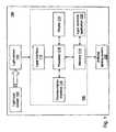
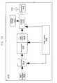
- Automated lighting system 100may include a light pipe system 102 , a light sensor 104 , a controller 106 , and an artificial lighting system 108 .
- Other natural lighting systemsmay be included such as skylights, windows, etc.
- Light pipe system 102provides natural light from the sun or moon to an interior space.
- Light sensor 104measures a light level in the interior space. For example, a light level may indicate a brightness using a numerical or relative scale.
- Light sensor 104may be positioned to measure the light level at or near a specific area of the interior space, such as a work area. Controller 106 controls artificial lighting system 108 based on the measured light level.
- Artificial lighting system 108may include lighting systems of different types, manufactures, and models.
- Controller 106may include a display 110 , an input interface 112 , a memory 112 , a communication interface 116 , a processor 118 , and a light controller application 120 .
- Display 110presents information to a user of controller 106 as known to those skilled in the art.
- display 110may be a thin film transistor display, a light emitting diode display, a liquid crystal display, or any of a variety of different displays known to those skilled in the art now or in the future.
- Input interface 112provides an interface for receiving information from the user for entry into controller 106 as known to those skilled in the art.
- Input interface 112may use various input technologies including, but not limited to, a keypad, a keyboard, a pen and touch screen, a mouse, a track ball, a touch screen, one or more buttons, a rotary dial, etc. to allow the user to enter information into controller 106 or to make selections presented in a user interface displayed on display 110 .
- Input interface 112may provide both an input and an output interface. For example, a touch screen both allows user input and presents output to the user.
- Controller 106may have one or more input interfaces that use the same or a different technology.
- Memory 114is an electronic holding place or storage for information so that the information can be accessed by processor 118 as known to those skilled in the art.
- Controller 106may have one or more memories that use the same or a different memory technology. Memory technologies include, but are not limited to, any type of RAM, any type of ROM, any type of flash memory, etc.
- Controller 106also may have one or more drives that support the loading of a memory media such as a compact disk, digital video disk, or a flash stick.
- Communication interface 116provides an interface for receiving and transmitting data between devices using various protocols, transmission technologies, and media as known to those skilled in the art.
- the communication interfacemay support communication using various transmission media that may be wired or wireless.
- Controller 106may include a plurality of communication interfaces that use the same or a different transmission technology.
- Processor 118executes instructions as known to those skilled in the art. The instructions may be carried out by a special purpose computer, logic circuits, or hardware circuits. Thus, processor 118 may be implemented in hardware, firmware, software, or any combination of these methods. The term “execution” is the process of running an application or the carrying out of the operation called for by an instruction. The instructions may be written using one or more programming language, scripting language, assembly language, etc. Processor 118 executes an instruction, meaning that it performs the operations called for by that instruction. Processor 118 operably couples with display 110 , with input interface 112 , with memory 114 , and with communication interface 116 to receive, to send, and to process information. Processor 118 may retrieve a set of instructions from a permanent memory device and copy the instructions in an executable form to a temporary memory device that is generally some form of RAM. Controller 106 may include a plurality of processors that use the same or a different processing technology.
- Light controller application 120performs operations associated with controlling a light level of an interior space. The operations may be implemented using hardware, firmware, software, or any combination of these methods. With reference to the exemplary embodiment of FIG. 1 , light controller application 120 is implemented in software stored in memory 114 and accessible by processor 118 for execution of the instructions that embody the operations of light controller application 120 . Light controller application 120 may be written using one or more programming languages, assembly languages, scripting languages, etc.
- Light sensor 104 and controller 106may be integrated into a single device. Light sensor 104 and controller 106 may be connected directly. For example, light sensor 104 may connect to controller 106 using a cable. Additionally, light sensor 104 may connect to controller 106 using a network that may be wired or wireless.
- light pipe system 102is shown in accordance with an exemplary embodiment.
- light pipe system 102is formed of components having a generally circular shape though other shapes may be used without limitation.
- Light pipe system 102may include a diffuser 200 , a reflective tube 202 , and a light collection system 204 .
- Reflective tube 202is a sheet of highly efficient, reflective material. For example, silver coated aluminum, MIRO®, etc. may be used as known to those skilled in the art.
- the sheet of reflective materialis rolled to form a tube having a wall 206 and joined along an joint 208 .
- the joint 208is joined using rivets 210 though other fastening methods and mechanisms may be used without limitation.
- Reflective tube 202may be formed to have a variety of lengths and to form a tube having a variety of diameters based on the characteristics of diffuser 200 , of light collection system 204 , of the roofing/wall defining the interior space, and of the interior space to be lit.
- Diffuser 200may be a prismatic diffuser.
- diffuser 200is mounted within reflective tube 202 so that a concave portion 212 is concave relative to the interior space.
- diffuser 200may include concave portion 212 and a tapered portion 214 .
- Tapered portion 214extends from concave portion 212 to transition a concave surface of concave portion 212 to form an approximately parallel surface to reflective tube 202 .
- a caulk 216may be used to seal diffuser 200 within wall 206 of reflective tube 202 to reduce condensation, dust, heat loss, and the build-up of other materials within an interior space formed by wall 206 of reflective tube 202 .
- Caulk 216may comprise a silicone material, such as hot melt silicone intended to provide superior adhesion and strength to the assembly.
- no fasteneris used to mount diffuser 200 within reflective tube 202 .
- a bead of caulk 216may be applied to an inner surface of wall 206 of reflective tube 202 near a mounting edge 218 .
- Mounting edge 218 of wall 206 of reflective tube 202may be positioned over diffuser 200 with concave portion 212 positioned as shown in FIGS. 2 a and 2 b .
- caulk 216fills any gap between wall 206 of reflective tube 202 and tapered portion 214 of diffuser 200 .
- the term “mount”includes join, unite, connect, associate, insert, hang, hold, affix, attach, fasten, bind, paste, secure, bolt, screw, rivet, solder, weld, and other like terms.
- light pipe system 102may further include a cone skirt 220 and reflector 222 .
- Cone skirt 220may be formed of a reflective material. Cone skirt 220 may be mounted to light pipe system 102 or may be mounted to an interior surface of the roofing/wall. Cone skirt 220 directs light toward the interior space to be lit.
- Reflector 222may be formed of a white reflective material such as Anolux® manufactured by Anofol S.r.l. of Italy. Reflector 222 may be positioned on an interior surface of reflective tube 202 above or adjacent to or overlapping caulk with 216 . In an exemplary embodiment, reflector 222 may have a length of approximately twelve inches. Reflector 222 reduces glare from diffuser 200 an increases light to the floor area.
- the wall 206 of reflective tube 202may include an artificial light source 221 disposed at or proximate a lower edge of the wall 206 (shown for example as substantially surrounding the outer perimeter of tube 202 at a lower end of wall 206 ).
- Such artificial light source 221may comprise an LED light in the form of a ring or string provided about the tube 202 .
- the light source 221may be formed integrally with the tube 202 , or attached separately as a new installation, or may facilitate use as an optional feature or as a retrofit on existing light pipe systems.
- the LED'smay be attached using any suitable method or mounting arrangement, such as adhesive, ring-clamp, band, strap, mounting frame, etc.
- the LEDsmay be attached directly to the wall 206 of tube 202 , or may be coupled indirectly by use of a supplemental LED mounting surface or device such as a bracket or other suitable fixture for positioning the LEDs at a suitable location for providing a desired light dispersion pattern.
- the optics for dispersing the light from light source 221are shown according to one embodiment as including the light source 221 disposed about an outside perimeter of tube 202 such that light emitted from light source 221 is reflected by reflector 222 of cone skirt 220 , so that the emitted light is directed downward toward the interior space in a desired pattern.
- Such a patternmay include emitting the light in a generally radially outward direction from the light pipe and reflecting the emitted light in a downward and generally radially opposite direction by the reflector 222 .
- other optics, configurations or reflective patternsmay be used to obtain a desired light distribution from the supplemental light source.
- other devicessuch as lenses or other forms of reflective devices may be used.
- Portions of the tube wall 206 and/or the reflector 220 and/or any supplemental LED mounting surface or devicemay have a high-emissivity coating or material applied thereto and intended to better reject heat generated by the LEDs.
- coatingmay be a paint, tape, or other suitable layer of a high emissivity material disposed on the reflector and/or the tube proximate the location of the LEDs to provide the desired heat rejection performance.
- a clamp, frame, or other suitable componentsuch component may also include the high emissivity coating.
- light source 221is intended to provide supplemental lighting to supplement the amount of external light transmitted to the interior space by the light pipe system during “intermediate” periods when available external light is almost, but not entirely, sufficient to provide the desired light level within the interior space, as detected by light sensors within the interior space.
- interior artificial lighting sourcesare controlled by light sensors within the interior space (i.e.
- the supplemental light from light source 221can be sufficient to delay or avoid energizing the artificial lighting sources during periods of “intermediate” external brightness, or if the artificial light sources are energized, the supplemental light from light source 221 may permit the artificial lighting sources to be de-energized.
- the supplemental light from light source 221is intended to provide a low-cost, efficient source of light that can minimize or avoid the need to energize interior artificial lighting during periods of intermediate external light availability.
- supplemental light source 221Operation of supplemental light source 221 may be controlled by the same sensors used to control the artificial lighting for the interior space. For example, when the sensors determine that the light level within the interior space has decreased to a predetermined level and increased lighting is required, the controllers for the artificial light sources may first send a signal to supplemental light source 221 to energize. When the sensors determine that the light level within the interior space has decreased to a predetermined level with the supplemental light source 221 energized and increased light level is still required, the controllers for the artificial light sources may then send a signal to de-energize supplemental light source 221 and to energize the artificial light source within the interior space according to a pre-established control scheme such as those further described herein.
- Supplemental light sources 221may be controlled by (or otherwise interface with) a wireless communication device such as a transceiver 219 operating on a suitable radio frequency or the like for communicating with the controller and/or sensors.
- a wireless communication devicesuch as a transceiver 219 operating on a suitable radio frequency or the like for communicating with the controller and/or sensors.
- light source 221may have a transceiver with an integrated sensor that directly controls operation of light source 221 and communicates the status of the light source 221 to the controller.
- transceiver 219is disposed on an outside surface of wall 206 and communicates with light source 221 through a suitable connection (e.g. wired connection, etc.).
- Transceiver 219may include a sensor for control of light source 221 and may be configured to interface or communicate with a master controller or transceiver, or with other local transceivers associated with other light pipes. Transceiver 219 may also include suitable control equipment for switching the light source on/off, and may include suitable memory for logging the time on/off of the supplemental light source. Transceiver 219 may also provide an appropriate switching device(s) for turning on and off a supply of electrical power to the LEDs (e.g. switches, relays, etc.) which are operably coupled to a suitable electrical power supply. According to one embodiment, the electrical power supply includes a solar power generating device such as (but not limited to) a photovoltaic panel 217 (see FIG.
- the electrical power supplymay be any suitable power supply available within (or available to) the facility, such as, but not limited to, an existing power supply for use with other artificial lighting devices in the facility.
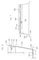
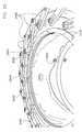
- light pipe system 102is further shown according to an exemplary embodiment to include a guard 223 disposed about the light-emitting end of the light pipe proximate the diffuser.
- Guard 223may be coupled to a ceiling or other surface through which the light pipe extends (as shown in FIG. 2 c ) to provide enhanced robustness and protection for the entire light pipe assembly in the event that the light pipe is inadvertently impacted from within the facility.
- the guardmay be coupled directly to an outer portion of the light pipe.
- the guardis formed from a material such as metal (e.g.
- galvanized or powder coated steel wire, stainless steel wire etc.such as may be fabricated by bending, rolling, etc. and welded at the junctions, or may be impact-resistant plastic formed in a suitable fabrication process (e.g. molding, etc.).
- the guardmay be formed from plastic-coated wire or other material having sufficient strength to resist impact and protect the light pipe, while withstanding the elements to which the light pipe may be exposed.
- the guardis formed in a substantially cylindrical shape with a side wall portion 225 (such as may be formed from a continuous helical spiral or stacked rings or the like interconnected by vertical ribs) and a bottom wall portion 227 (such as may be formed from a flat spiral or concentric rings or the like interconnected by radially extending spokes that transition to the vertical ribs) having wire spacing between approximately 1-3 inches to prevent entry by objects such as baseballs, tennis balls and the like, yet minimize any reduction in light emission from the light pipe.
- the guardmay have any suitable wire spacing or pattern to suit a desired application.
- the guardmay be configured for use with a light pipe having an angular diffuser, such as that shown and described with reference to FIG. 38 .
- the bottom wall portion 225 and side wall portions 227are formed from a single wire 229 spirally wound from the center of the bottom wall to the outer edge of the bottom wall (where it joins the lower edge of the side wall) where a ring is formed, and then helically wound from the lower edge of the side wall to the upper edge of the side wall, where the wire is wound to form a ring.
- the wire of the spirally and helically wound wall portionsis secured by radially extending wires 231 (e.g. spokes/ribs, etc.) that originate at or near the center of the bottom wall, and are bend at substantially 90 degrees at the outer edge of the bottom wall and lower edge of the side wall.
- the ribs 231may extend above the ring at the upper end of the side wall 227 and are then bent at an angle of substantially 90 degrees and closed in a loop 233 (e.g. an attachment/fastening loop or eye, etc.) that is substantially parallel to a ceiling surface for use in fastening the guard to a ceiling surface with suitable fasteners or the like.
- a loop 233e.g. an attachment/fastening loop or eye, etc.
- At least several of the wire loops 233may be arranged in a variably offset pattern or “turned” relative to the others (e.g. in a manner such that the loops are asymmetric with respect to one another and/or to the guard), for adaptation to ceiling surfaces having ridges or ribs (e.g.
- Attachment of the guard to a relatively secure structure surrounding the light pipeis also intended to provide an enhancement for security of the building by providing a barrier or obstacle to unauthorized access to the facility by an intruder through the light pipe.
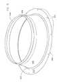
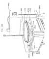
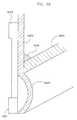
- Light collection system 204may include a light collector 300 , a clamp ring 302 , a mounting flange 304 , and a flashing 306 .
- Flashing 306is positioned to encircle and to mount to a first portion of reflective tube 202 .
- the first portion of reflective tube 202is opposite diffuser 200 .
- Flashing 306is positioned on a surface to which the light pipe system is mounted for use.
- the surfacefor example, may be a roof or an exterior wall of a building. Flashing 306 may be formed of aluminum.
- Reflective tube 202extends through the surface to the interior space to allow natural light into the interior space.
- Mounting flange 304mounts to a first portion of flashing 306 opposite the surface to which the flashing 306 is mounted.
- light collector 300includes a shell 404 and a flange 406 .
- light collector 300is formed of a sheet of acrylic material using a free forming process that uses air pressure differentials to form shell 404 of light collector 300 without a mold as described with reference to FIG. 23 .
- shell 404has an oblate shape. Products formed using this method generally have improved optical characteristics over those formed using molds.
- Flange 406 of light collector 300defines a generally circular opening which is positioned so that shell 404 covers the interior space formed by reflective tube 202 .
- Clamp ring 302is positioned over flange 406 of light collector 300 .
- Clamp ring 302may include first fastener holes 400 .
- Mounting flange 304may include a flange 408 and a wall 410 which extends from flange 408 at an approximately 90 degree angle though other angles may be used. In an exemplary embodiment, flange 408 and wall 410 extend approximately 1.5 inches.
- Flange 408 of mounting flange 304may include second fastener holes 402 .
- first fastener holes 400are formed in clamp ring 302 to align with second fastener holes 402 of mounting flange 304 so that flange 406 of light collector 300 can be mounted and held between clamp ring 302 and flange 408 of mounting flange 304 .
- Mounting flange 304 and clamp ring 302may be formed of aluminum.
- FIG. 5a side view of light collection system 204 is shown in accordance with an exemplary embodiment.
- wall 410 of mounting flange 304frictionally abuts the first portion of flashing 306 .
- Flange 408 of mounting flange 304extends outward away from the interior space formed by reflective tube 202 .
- Flange 406 of light collector 300is positioned against flange 408 of mounting flange 304 .
- Clamp ring 302is positioned against flange 406 of light collector 300 .
- flashing 306is shown in accordance with an exemplary embodiment.
- flashing 306is formed of a single sheet of spun aluminum with no seams.
- Flashing 306may include a wall 600 , a transition wall 602 , a flange 604 , a mounting wall 606 , and a peripheral edge 608 .
- Transition wall 602extends from a first side of wall 600 of flashing 306 .
- Flange 604 of flashing 306extends from a first side of transition wall 602 .
- the first side of transition wall 602is opposite wall 600 of flashing 306 .
- Transition wall 602provides a transitional surface between wall 600 and flange 604 of flashing 306 .
- Mounting wall 606extends from a second side of wall 600 of flashing 306 .
- the second side of transition wall 602is opposite the first side of transition wall 602 .
- Peripheral edge 608forms a generally circular shape along mounting wall 606 opposite the second side of wall 600 of flashing 306 .
- roofing or siding materialsmay be positioned to cover at least a portion of flashing 306 including flange 604 , transition wall 602 , and/or wall 600 .
- transition wall 602forms an angle ⁇ between wall 600 and flange 604 of flashing 306 .
- angle ⁇is greater than 90 degrees.
- Mounting wall 606may include a first mounting surface 702 , a transition surface 704 , and a second mounting surface 706 .
- First mounting surface 702extends from an edge 700 of wall 600 of flashing 306 .
- Transition surface 704provides a transition between first mounting surface 702 and second mounting surface 706 .
- Peripheral edge 608is formed along second mounting surface 706 .
- wall 600 of flashing 306extends a height B from flange 604 of flashing 306 to edge 700 .
- height Bis approximately six inches for a light pipe including a diffuser having a diameter of 22.25 inches.
- First mounting surface 702extends a height C from edge 700 to transition surface 704 .
- height Cis approximately 1.5 inches for a light pipe including a diffuser having a diameter of 22.25 inches.
- First mounting surface 702extends in a generally perpendicular direction relative to a horizontal surface 800 .
- Transition surface 704extends in a generally parallel direction relative to horizontal surface 800 .
- Second mounting surface 706extends a height D from transition surface 704 to peripheral edge 608 .
- height Dis approximately one inch for a light pipe including a diffuser having a diameter of 22.25 inches.
- Second mounting surface 706extends in a generally perpendicular direction relative to horizontal surface 800 .
- flange 604 of flashing 306is parallel to or extends down from horizontal surface 800 .
- horizontal surface 800extends in the direction of the surface to which the light pipe system is mounted.
- Flange 604 of flashing 306extends a length E from transition wall 602 .
- length Eis approximately three inches for a light pipe including a diffuser having a diameter of 22.25 inches.
- FIG. 9 aa detailed cross sectional side view of the mounting between light collection system 204 and reflective tube 202 is shown in accordance with an exemplary embodiment.
- Wall 410 of mounting flange 304frictionally abuts first mounting surface 702 of flashing 306 to maintain light collector 300 in position relative to flashing 306 .
- a fastener 900extends through a first fastener hole of the first fastener holes 400 and through a first fastener hole of the second fastener holes 402 to mount clamp ring 302 to flange 408 of mounting flange 304 .
- fastener 900includes a screw 902 , a nut 904 , and a washer 906 .
- screw 902is a one inch screw formed of aluminum.
- nut 904is a nylon locking hex nut formed of aluminum.
- washer 906is formed of aluminum.
- a different fastening mechanismmay be used to connect the components of light pipe system 102 .
- a question mark fastenercomprising a band clamp or a barrel clamp type of fastener may be used with a T-bolt or straight hex bolt to close the clamp.
- Flange 408 of mounting flange 304 and flange 406 of light collector 300are positioned within an open upper end of the question mark section of the question mark fastener.
- the clampmay replace fastener 900 and clamp ring 302 .
- a V-section clampmay also be used with bolt anchor points added to a V section of the V-section clamp.
- a first gasket 908may be positioned between first mounting surface 702 of flashing 306 and wall 206 of reflective tube 202 to abut against transition surface 704 of mounting wall 606 .
- first gasket 908is a horsehair gasket.
- a second gasket 910may be positioned between shell 404 of light collector 300 and second mounting surface 706 of flashing 306 .
- second gasket 910is a horsehair gasket.
- First gasket 908 and second gasket 910reduce airflow and keep contaminants from entering light pipe system 102 . Fewer or additional gaskets may be included.
- siliconemay be applied between flashing 306 and reflective tube 202 to reduce airflow and keep contaminants from entering light pipe system 102 .
- a second fastener 912extends through a first fastener hole in second mounting surface 706 of flashing 306 and through a first fastener hole of wall 206 of reflective tube 202 to mount flashing 306 to reflective tube 202 .
- Second fastener 912extends into the interior space formed by reflective tube 202 .
- Second fastener 912is positioned above flange 406 of light collector 300 along shell 404 of light collector 300 .
- second fastener 912is a sheet metal screw formed of stainless steel.
- Clamp ring 302may be formed of a plurality of sections which may overlap to form various size rings.
- FIG. 9 ba detailed cross sectional side view of a mounting between flashing 306 and mounting flange 304 is shown in accordance with an exemplary embodiment.
- Wall 410 of mounting flange 304frictionally abuts first mounting surface 702 of flashing 306 to maintain light collector 300 in position relative to flashing 306 .
- a joint 914may be formed between wall 410 of mounting flange 304 and first mounting surface 702 of flashing 306 .
- joint 914may be formed using a Tog-L-Loc® sheet metal joining system such as that developed by BTM Corporation of Marysville, Mich.
- a sealantalso may be applied between wall 410 of mounting flange 304 and first mounting surface 702 of flashing 306 to minimize any airflow or water leakage between wall 410 of mounting flange 304 and first mounting surface 702 of flashing 306 .
- an insulation sleevemay be positioned between flashing 306 and reflective tube 202 to reduce airflow and keep contaminants from entering light pipe system 102 and to reduce heat loss from light pipe system 102 .
- the insulation sleevemay be formed of a fiberglass material.
- the insulation sleevemay be taped to an inside surface of flashing 306 and may extend from approximately adjacent first gasket 908 to the roofing/wall or 2-3 inches below/into the roofing/wall.
- a counter flashingmay be positioned between mounting flange 304 and an exterior surface of the roofing/wall to deflect moisture away from light pipe system 102 .
- the counter flashingmay be mounted to mounting flange 304 using first fastener holes 400 and second fastener holes 402 .
- a plurality of rodsmay mount to mounting flange 304 extending upward toward shell 404 .
- a filamentmay be extended between the plurality of rods to discourage birds from roosting on light pipe system 102 .
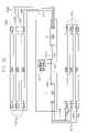
- Light fixture 1000may include a reflective sheet 1002 , a support frame 1004 , a first lamp holder 1006 , a second lamp holder 1008 , a first raceway cover 1010 , a second raceway cover 1012 , a ballast cover 1014 , and a power connector 1016 .
- Light fixture 1000may mount to or otherwise suspend from a ceiling as known to those skilled in the art.
- first raceway cover 1010 , second raceway cover 1012 , and/or ballast cover 1014may mount to the ceiling.
- Power connector 1016can be connected to a power supply connector to provide power to light fixture 1000 .
- First lamp holder 1006 and second lamp holder 1008include one or more sockets for mounting opposed ends of a lamp.
- light fixture 1000includes six pairs of sockets to connect with six lamps.
- the lampsare fluorescent tubes.
- Reflective sheet 1002may mount to support frame 1004 .
- Reflective sheet 1002reflects light from the lamps toward the interior space to be lit and may include a peak formed to accommodate a lamp.
- Support frame 1004may form a generally “I” shaped cavity. The center of the “I” shaped cavity may support one or more ballasts and wiring to first lamp holder 1006 and to second lamp holder 1008 .
- the ends of the “I” shaped cavitymay support first lamp holder 1006 and second lamp holder 1008 .
- First raceway cover 1010fits over a first end of the “I” shaped cavity of support frame 1004 to enclose first lamp holder 1006 .
- Second raceway cover 1012fits over a second end of the “I” shaped cavity of support frame 1004 to enclose second lamp holder 1008 .
- Ballast cover 1014fits over the center of the “I” shaped cavity of support frame 1004 to enclose the one or more ballasts and associated wiring.
- Power connector 1016extends through an aperture 1100 through ballast cover 1014 .
- power connector 1016may be a 6-pin “Mate-N-Lock” socket connector of the type sold by the AMP division of Tyco Electronics of Harrisburg, Pa.
- light fixture 1000includes a first ballast 1102 and a second ballast 1104 with each ballast providing power to three of the six lamps.
- first ballast 1102 and second ballast 1104may be a model 49776 electronic ballast available from GE Lighting of Cleveland, Ohio.
- a fewer or a greater number of ballastsmay be used that may include a fewer or a greater number of lamps per ballast.
- FIG. 12a wiring diagram of light fixture 1000 is shown in accordance with an exemplary embodiment. As stated previously, in the exemplary embodiment of FIG. 11 , light fixture 1000 includes six pairs of sockets to connect with six lamps 1200 which are fluorescent tubes.
- a first wire 1202connects first ballast 1102 with a “hot” line of power connector 1016 .
- a second wire 1204connects first ballast 1102 with a ground line of power connector 1016 .
- a first output wire 1206connects first ballast 1102 with a first socket.
- a second socket and a third socketare connected in daisy chain fashion to the first socket using first sockets 1208 which may be included in first lampholder 1006 as known to those skilled in the art.
- Second sockets 1210connect with the first lamp, the second lamp, and the third lamp at opposite ends relative to first sockets 1208 .
- Second sockets 1210may be included in second lampholder 1008 as known to those skilled in the art.
- Three wires 1212connect second sockets 1210 with first ballast 1102 .
- a third wire 1214connects second ballast 1104 with a “hot” line of power connector 1016 .
- a fourth wire 1216connects second ballast 1104 with a ground line of power connector 1016 .
- a first output wire 1218connects second ballast 1104 with a fourth socket.
- a fifth socket and a sixth socketare connected in daisy chain fashion to the fourth socket using third sockets 1220 which may be included in second lampholder 1008 as known to those skilled in the art.
- Fourth sockets 1222connect with the fourth lamp, the fifth lamp, and the sixth lamp at opposite ends relative to third sockets 1220 .
- Fourth sockets 1222may be included in first lampholder 1006 as known to those skilled in the art.
- Three wires 1224connect fourth sockets 1222 with second ballast 1104 .
- light fixture 1000includes two independently controllable lamp circuits which may be the same or different. If used with a dimmable ballast, additional control signal lines may connect power connector 1016 with first ballast 1102 and/or second ballast 1104 .
- First lighting system 108 amay be an example implementation of artificial lighting system 108 .
- First lighting system 108 amay include a plurality of light fixtures 1300 .
- One or more of the plurality of light fixtures 1300may be implemented as a light fixture 1000 .
- One or more of the plurality of light fixtures 1300may be the same or may be different.
- a receiver 1302which receives a control signal from a transmitter 1304 .
- the control signalmay include a lighting indicator specific to each light fixture of the plurality of light fixtures 1300 or may include the same lighting indicator for each of the plurality of light fixtures 1300 .
- the control signalmay include a lighting indicator specific to each independently controllable lamp circuit of each light fixture.
- the lighting indicatormay indicate on/off or may indicate a lighting level.
- Each receiver 1302may be assigned an address unique to the receiver, unique to the plurality of light fixtures 1300 , and/or unique to the independently controllable lamp circuit of each light fixture.
- the same or different addressesmay be assigned to each receiver/independently controllable lamp circuit, and the control signal may include an address for each independently controllable lamp circuit of each light fixture, an address for each light fixture of the plurality of light fixtures 1300 , or an address for the plurality of light fixtures 1300 with an associated lighting indicator.
- a single receiver 1302may be used to control the supply of power to multiple light fixtures that are “daisy chained” together using a “daisy chain” modular wiring system power supply line such as the one described in U.S. Pat. No. 6,746,274.
- Transmitter 1304may send the control signal using a radio frequency to any receivers 1302 within an effective range 1306 defined based on the characteristics of the transmitter as known to those skilled in the art.
- transmitter 1304can simultaneously control one or more light fixtures/independently controllable lamp circuits.
- Transmitter 1304may be configured to encode a receiver address in the control signal.
- Each receiver 1302may be configured to respond only to control signals encoded with its receiver address.
- the light fixture associated with each receiver 1302can be turned on or off or dimmed based on the value of the lighting indicator.
- the address and lighting indicator informationmay be encoded in the control signal using a variety of methods as known to those skilled in the art.
- Transmitter 1304may include a power supply 1400 , an input interface 1402 , a controller 1404 , an optoisolator 1406 , a logic circuit 1408 , an encoder 1410 , address jumpers 1412 , a modulator 1414 , and an antenna 1416 .
- Transmitter 1304may include additional or different components.
- transmitter 1304may include a display.
- Power supply 1400provides power to transmitter 1304 .
- Controller 1404can be any suitable logic device, for example, a microprocessor or microcontroller, programmable logic controller, custom logic circuitry, etc.
- Input interface 1402provides an interface for receiving information from the user for input to controller 1404 as known to those skilled in the art.
- Input interface 1402may use various input technologies including, but not limited to, a keypad, a keyboard, a pen and touch screen, a mouse, a track ball, a touch screen, one or more buttons, a rotary dial, etc. to allow the user to enter information into controller 1404 or to make selections presented in a user interface displayed on the display.
- Input interface 1402may provide both an input and an output interface. For example, a touch screen both allows user input and presents output to the user.
- Transmitter 1304may have one or more input interfaces that use the same or a different technology.
- Logic circuit 1408may monitor the input to input interface 1402 .
- logic circuit 1408may monitor keystrokes entered into input interface 1402 .
- the usermay enter information into transmitter 1304 such as a value of the lighting indicator.
- Address jumpers 1412may provide a receiver address of a destination receiver.
- Encoder 1410encodes the entered lighting indicator and the provided receiver address into a baseband signal supplied to modulator 1414 .
- encoder 1410may be a model PT2262 remote control encoder sold by Princeton Technology Corp. of Sindian City, Taipei 23145, Taiwan. Other encoders may be used.
- Modulator 1414provides a modulated signal to antenna 1416 for sending the control signal.
- modulator 1414is a radio frequency modulation circuit constructed of discrete components or using an integrated circuit.
- Receiver 1302may include an antenna 1500 , a power supply 1502 , a demodulator 1504 , a decoder 1506 , address jumpers 1508 , a controller 1510 , an output selector 1512 , and one or more relays 1514 depending on the number of independently controllable lamp circuits.
- Receiver 1302may include additional or different components.
- Antenna 1500receives the control signal, for example, from transmitter 1304 .
- antenna 1500may receive a radio frequency signal.
- Power supply 1502provides power to receiver 1302 .
- Demodulator 1504demodulates the received control signal to a baseband signal.
- demodulator 1504may be a model TDL9927 superheterodyne receiver sold by Foshan Tuodi Electronics Co., Ltd. of Bao'an District of Shenzhen City, Guangdong province, China.
- Decoder 1506decodes the demodulated control signal to extract the values of the receiver address and the lighting indicator.
- decoder 1506may be a model PT2272 remote control decoder sold by Princeton Technology Corp. of Sindian City, Taipei 23145, Taiwan.
- Address jumpers 1508may be used to define the address of receiver 1302 and to provide the address to decoder 1506 for comparison with the receiver address extracted from the control signal. Decoder 1506 may recognize only control signals encoded with a receiver address that matches the address of receiver 1302 . In an alternative embodiment, decoder 1506 may recognize all received control signals, irrespective of the receiver address encoded in the control signal. Controller 1510 may determine which control signals to process based on a receiver address supplied to controller 1510 , for example, using switches, address jumpers 1508 , values stored in a memory, etc.
- Controller 1404can be any suitable logic device, for example, a microprocessor or microcontroller, programmable logic controller, custom logic circuitry, etc.
- controller 1404includes an output bus that supplies the extracted value of the lighting indicator to output selector 1512 .
- output selector 1512includes output configuration jumpers which select one or more of the one or more relays 1514 . Using relay outputs, an independently controllable lamp circuit can be turned on or off based on the value of the lighting indicator.
- receiver 1302may control the supply of power to a light fixture by connecting a supply of electrical power to a first terminal of a first relay, and connecting a second terminal of the first relay to the power input terminal of a circuit powering a lamp or group of lamps in the light fixture.
- the state of the relaychanges to either a closed circuit to supply power to the lamp or group of lamps in the circuit, or an open circuit to remove power from the circuit.
- dimmer circuitrymay be used instead of relays to control each independently controllable lamp circuit based on a light level defined by the extracted value of the lighting indicator.
- Receiver 1302may be used to control a dimmable ballast in the light fixture. In this configuration, power may be connected directly to the light fixture. Receiver 1302 provides a low voltage control signal to the dimmable ballast. The low voltage control signal could be generated, for example, by a resistive divider network configured by output selector 1512 . The low voltage control signal may be supplied to one or more of the one or more relays 1514 by output selector 1512 . The other side of the relay may be connected to a control signal input terminal on a dimmable electronic ballast in the light fixture. Instead of using relays to supply the low voltage control signals, receiver 1302 may include one or more digital to analog converter circuits to provide continuously variable low voltage control signals to the dimmable ballast in the light fixture according to the extracted value of the lighting indicator.
- a transmittermay integrate with or otherwise interact with controller 106 .
- a second lighting system 108 bis shown in accordance with a second exemplary embodiment.
- Second lighting system 108 bmay be an example implementation of artificial lighting system 108 integrated with light sensor 104 and/or controller 106 .
- Second lighting system 108 bmay include the plurality of light fixtures 1300 .
- One or more of the plurality of light fixtures 1300may be the same or may be different.
- receiver 1302Associated with each of the plurality of light fixtures 1300 is receiver 1302 which receives a control signal from a controller 1600 .
- controller 1600is shown in accordance with an exemplary embodiment. Controller 1600 may send the control signal using a radio frequency to any receivers 1302 within an effective range 1306 . Thus, controller 1600 can simultaneously control one or more light fixtures/independently controllable lamp circuits. Controller 1600 may be configured to encode a receiver address in the control signal. Controller 1600 may include light sensor 104 , display 110 , input interface 112 , memory 114 , processor 118 , light controller application 120 , and a transmitter 1700 . Light sensor 104 and controller 1600 may be integrated into a single device. Light sensor 104 and controller 1600 may be connected directly. For example, light sensor 104 may connect to controller 1600 using a cable. Different and additional components may be incorporated into controller 1600 . For example, controller 1600 may include a communication interface which allows light sensor 104 to connect to controller 1600 using a network that may be wired or wireless.
- Light controller application 120may determine the receiver addresses and the value of the lighting indicator for each receiver address using a light level measured by light sensor 104 .
- Light sensor 104may periodically measure a light level and store the measured light level in memory 114 so that light controller application 120 can access the information.
- light sensor 104may be configured to send the measured light level in a message to light controller application 120 without storing the value in memory 114 .
- Light controller application 120may accept a lighting control value entered by a system user to set the desired light level in the interior space. For example, the user may enter the desired light level using input interface 112 . The user may enter a table of desired light levels which may define the desired light level, for example, as a function of the time of day, of the date, etc. The desired light level(s) may be stored in memory 114 . Light controller application 120 compares the desired light level with the light level measured by light sensor 104 and received by light controller application 120 . Based on the comparison, light controller application 120 determines the receiver addresses and the value of the lighting indicator for each receiver address. Light controller application 120 may interact with a plurality of light sensors and a plurality of transmitters.
- Transmitter 1700may include an encoder 1702 , modulator 1414 , and antenna 1416 .
- Encoder 1702receives the determined receiver addresses and lighting indicator values for each receiver address.
- Encoder 1702encodes the received addresses and lighting indicators into a baseband signal supplied to modulator 1414 .
- Third lighting system 108 cmay be an example implementation of artificial lighting system 108 .
- Third lighting system 108 cmay include the plurality of light fixtures 1300 , a transmitter 1304 , a first repeater 1800 , and a second repeater 1804 .
- One or more of the plurality of light fixtures 1300may be the same or may be different.
- receiver 1302Associated with each of the plurality of light fixtures 1300 is receiver 1302 which receives a control signal from transmitter 1304 , first repeater 1800 , and/or second repeater 1804 .
- transmitter 1600may be incorporated into third lighting system 108 c instead of or in addition to transmitter 1304 .
- First repeater 1800is positioned within effective range 1306 to reliably receive a control signal from transmitter 1304 .
- First repeater 1800may receive the control signal from transmitter 1304 and send the control signal using a radio frequency to any receivers 1302 within a first repeater effective range 1802 .
- first repeater 1800can simultaneously control one or more light fixtures/independently controllable lamp circuits.
- Second repeater 1804may be positioned outside effective range 1306 , but within first repeater effective range 1802 .
- Second repeater 1804may receive the control signal from first repeater 1800 and send the control signal using a radio frequency to any receivers 1302 within a second repeater effective range 1806 .
- Second repeater 1804the plurality of light fixtures 1300 positioned outside effective range 1306 and outside first repeater effective range 1802 can be controlled.
- Transmitter 1304may be configured to encode a receiver address or a repeater address in the control signal.
- the address assigned to each repeateris different from any address assigned to a receiver 1302 .
- Transmitter 1304may send control signals to receivers within effective range 1306 .
- transmitter 1304may be configured to encode only a repeater address in the control signal so that transmitter 1304 does not send control signals encoded for processing by receivers 1302 .
- the plurality of light fixturesare positioned within first repeater effective range 1802 or second repeater effective range 1806 .
- First repeater 1800sends control signals to the receivers 1302 within first repeater effective range 1802 and to second repeater 1804 .
- Second repeater 1804sends control signals to the receivers 1302 within second repeater effective range 1806 .
- first repeater 1800 and second repeater 1804may encode a receiver address and/or a repeater address with the lighting indicator value.
- Additional repeatersmay be positioned within effective range 1306 , first repeater effective range 1802 , and/or second repeater effective range 1806 to provide additional areas of coverage. Use and positioning of repeaters provides lighting control over a potentially wide area and around obstacles and/or electromagnetic interference sources.
- first repeater 1800is shown in accordance with an exemplary embodiment.
- First repeater 1800 and second repeater 1804may be the same or may be different.
- First repeater 1800may include a receive antenna 1900 , a power supply 1902 , a demodulator 1904 , first address jumpers 1906 , a decoder 1908 , a controller 1910 , second address jumpers 1912 , a repeater encoder 1914 , third address jumpers 1916 , a receiver encoder 1918 , a modulator 1920 , and a transmit antenna 1922 .
- First repeater 1800may include a single antenna which acts as a transceiver for both receiving and transmitting signals.
- First repeater 1800may include additional or different components.
- Receive antenna 1900receives the control signal, for example, from transmitter 1304 .
- Receive antenna 1900may receive a radio frequency signal.
- Power supply 1902provides power to first repeater 1800 .
- Demodulator 1904demodulates the received control signal to a baseband signal.
- demodulator 1904may be a model TDL9927 superheterodyne receiver sold by Foshan Tuodi Electronics Co., Ltd. of Bao'an District of Shenzhen City, Guangdong province, China.
- First address jumpers 1906may be used to define the address of first repeater 1800 and to provide the address to decoder 1908 for comparison with the repeater address extracted from the control signal. Decoder 1908 decodes the demodulated control signal to extract the values of the repeater address.
- decoder 1908may be a model PT2272 remote control decoder sold by Princeton Technology Corp. of Sindian City, Taipei 23145, Taiwan. Decoder 1908 may respond to only control signals encoded with a repeater address that matches the address of first repeater 1800 . In an alternative embodiment, decoder 1908 may respond to all received control signals, irrespective of the repeater address encoded in the control signal. Decoder 1908 decodes the demodulated control signal to extract one or more receiver address and associated lighting indicator value.
- Controller 1910may determine which control signals to process based on a repeater address supplied to controller 1910 , for example, using switches, first address jumpers 1906 , values stored in a memory, etc.
- Controller 1910can be any suitable logic device, for example, a microprocessor or microcontroller, programmable logic controller, custom logic circuitry, etc.
- Controller 1910includes an output bus that supplies the extracted one or more receiver address and associated lighting indicator values to an appropriate encoder.
- Second address jumpers 1912may be used to define the address of second repeater 1804 and to provide the address to repeater encoder 1914 .
- Repeater encoder 1914encodes the extracted one or more receiver address and associated lighting indicator values and the repeater address provided by second address jumpers 1912 into a baseband signal supplied to modulator 1920 .
- repeater encoder 1914may be a model PT2262 remote control encoder sold by Princeton Technology Corp. of Sindian City, Taipei 23145, Taiwan. Other encoders may be used.
- Third address jumpers 1916may be used to define the address of one or more receivers 1302 and to provide the address to receiver encoder 1918 .
- Receiver encoder 1918encodes the receiver address provided by third address jumpers 1916 the lighting indicator value associated with the receiver address into a baseband signal supplied to modulator 1920 .
- receiver encoder 1918may be a model PT2262 remote control encoder sold by Princeton Technology Corp. of Sindian City, Taipei 23145, Taiwan. Other encoders may be used.
- Additional second address jumpers 1912 and repeater encoder 1914 combinationsmay be used, for example, if first repeater 1800 is responsible for communicating with multiple repeaters positioned within first repeater effective range 1802 .
- First repeater 1800may not include second address jumpers 1912 and repeater encoder 1914 if a repeater is not positioned within first repeater effective range 1802 .
- Additional third address jumpers 1916 and receiver encoder 1918 combinationsalso may be used, for example, if receivers are assigned different addresses in order to independently control the lighting level at different light fixtures and first repeater 1800 is responsible for communicating with multiple receivers positioned within first repeater effective range 1802 .
- Light fixtures/independently controllable lamp circuitsmay be controlled independently or based on defined groupings depending on how the receive addresses are defined. For example, if all receivers 1302 are assigned the same address, the light fixtures/independently controllable lamp circuits are controlled using the same lighting indicator value. If all receivers 1302 are assigned a unique address, the light fixtures/independently controllable lamp circuits can be controlled independently using potentially different lighting indicator values associated with each receiver address. Additionally, receivers 1302 may divided into sub-groups which have a common address within the group so that groups of light fixtures/independently controllable lamp circuits can be controlled independently using potentially different lighting indicator values associated with each group address. Repeaters and/or receivers may receive multiple control signals thereby providing signal redundancy and increasing system reliability. A ping-pong effect is avoided through the use of uniquely assigned repeater addresses and assigned repeater communication paths based on the address jumpers and repeater encoders.
- Modulator 1920provides a modulated signal to transmit antenna 1922 for sending the control signal to second repeater 1804 and/or one or more receivers 1302 .
- modulator 1920is a radio frequency modulation circuit constructed of discrete components or using an integrated circuit. Additionally, in an exemplary embodiment, modulator 1920 is configured to provide amplitude shift keying modulation and/or frequency shift keying modulation at a nominal operating frequency of 315 megahertz (MHz) with a transmission power of about 6 millivolts/meter (mV/m) at 3 meters. However, this is not required, and other operating frequencies, modulation schemes, and transmission power levels can be used.
- Transmitter 1304 , 1600 , receiver 1302 , and first repeater 1800may be designed to qualify as unlicensed radio frequency devices under the Federal Communications Commission rules found in 47 C.F.R. 15.
- lighting level datais received from light sensor 104 .
- the received lighting level datais compared with a lighting level setting.
- the lighting level settingmay indicate a desired brightness using a numerical scale.
- the desired brightnessalso may indicate a dim level for a light fixture which may be continuously variable.
- the lighting level settingmay be one to indicate lights on and zero to indicate lights off.
- the lighting level settingmay be a scale between 1 and 4, 1 and 10, etc.
- a lighting indicator valueis determined based on the comparison. Depending on the embodiment, multiple lighting indicator values may be determined for different light fixtures/independently controllable lamp circuits.
- a receiver addressis identified for receiving the determined lighting indicator value.
- multiple receiversmay receive the same lighting indicator value.
- each receivermay receive a different lighting indicator value.
- each receivermay have a unique address, may have the same address, or may have a receiver group address.
- a control signalis defined for the identified receiver.
- the control signalincludes the lighting indicator value.
- the control signalmay be encoded and modulated.
- Multiple control signalsmay be defined if multiple receivers are sent independent lighting indicator values.
- the defined control signalis sent to the identified receiver.
- the defined control signalmay be sent by a transmit antenna using a radio frequency pulse.
- one or more repeater addressis identified for receiving the determined lighting indicator value associated with one or more receiver address.
- a repeater of the identified repeater(s)is selected.
- a control signalis defined for the selected repeater.
- the control signalincludes the address for the selected repeater and the determined lighting indicator value(s) associated with one or more receiver address.
- the control signalmay be encoded and modulated.
- the defined control signalis sent to the selected repeater.
- the defined control signalmay be sent by a transmit antenna using a radio frequency pulse.
- a determinationis made concerning whether or not another repeater was identified in operation 2012 . If another repeater was identified in operation 2012 , processing continues at operation 2014 . If another repeater was not identified in operation 2012 , processing continues at operation 2000 .
- exemplary operations that may be associated with first repeater 1800are described. Additional, fewer, or different operations may be performed, depending on the embodiment. The order of presentation of the operations is not intended to be limiting.
- a control signalis received.
- the control signalmay be received by a receive antenna.
- a repeater addressis identified from the received control signal.
- the control signalmay be demodulated and/or decoded to extract the repeater address.
- the extracted repeater addressis compared with a local repeater address of first repeater 1800 .
- an operation 2106a determination is made concerning whether or not there is a match between the identified repeater address and the repeater address based on the comparison. If there is not a match between the identified repeater address and the repeater address, processing continues in an operation 2108 . In operation 2108 , the control signal is ignored.
- a lighting indicator valueis identified from the control signal.
- a receiver address associated with the lighting indicator valueis identified.
- multiple lighting indicator valuesmay be determined for different light fixtures/independently controllable lamp circuits.
- a control signalis defined for the identified receiver.
- the control signalis sent to the identified receiver. A control signal may be defined and sent for each identified receiver. Thus, a plurality of control signals may be sent.
- one or more repeater addressis identified for receiving the determined lighting indicator value(s) associated with one or more receiver address.
- a repeater of the identified repeater(s)is selected.
- a control signalis defined for the selected repeater.
- the control signalincludes the address for the selected repeater and the determined lighting indicator value(s) associated with one or more receiver address.
- the control signalmay be encoded and modulated.
- the defined control signalis sent to the selected repeater.
- the defined control signalmay be sent by a transmit antenna using a radio frequency pulse.
- a determinationis made concerning whether or not another repeater was identified in operation 2118 . If another repeater was identified in operation 2118 , processing continues at operation 2120 by selecting the next repeater. If another repeater was not identified in operation 2118 , processing continues at operation 2100 .
- a control signalis received.
- the control signalmay be received by a receive antenna.
- a receiver addressis identified from the received control signal.
- the control signalmay be demodulated and/or decoded to extract the receiver address.
- the identified receiver addressis compared with a local receiver address of receiver 1302 .
- a determinationis made concerning whether or not there is a match between the identified receiver address and the local receiver address based on the comparison. If there is not a match between the identified receiver address and the local receiver address, processing continues in an operation 2208 . In operation 2208 , the control signal is ignored.
- a lighting indicator valueis identified from the control signal. Depending on the embodiment, multiple lighting indicator values may be determined for independently controllable lamp circuits.
- the light level of the light fixtureis adjusted based on the identified lighting indicator value.
- a control signalmay be received for each independently controllable lamp circuits. Thus, a plurality of control signals may be received and processed to adjust the light level of the light fixture.
- a positioning clampis positioned on a seal of a vacuum molder.
- a vacuum molder 2400is shown in accordance with an exemplary embodiment.
- Vacuum molder 2400may include a tub 2402 , a vacuum draw tube 2404 , a seal 2406 , and clamps 2408 .
- Tub 2402includes a circumferential edge 2510 .
- Tub 2402is sized and shaped based on a shape and a size of the desired formed product.
- tub 2402may have a generally cylindrical shape.
- Positioning clamp 2500is positioned over seal 2406 and centered over tub 2402 in accordance with an exemplary embodiment.
- Positioning clamp 2500may include fastener holes 2502 , a plurality of centering pins 2504 , and a plurality of light collector centering pins 2506 .
- positioning clamp 2500may include eight fastener holes 2502 , two centering pins 2504 , and three light collector centering pins 2506 distributed about a circumference of positioning clamp 2500 .
- the three light collector centering pins 2506may form an equilateral triangle to accurately center light collector material on positioning clamp 2500 .
- Positioning clamp 2500may be formed of metal material. Positioning clamp 2500 may include an inner edge 2600 that faces an interior of tub 2402 . Inner edge 2600 may be curved to form a transition angle between flange 406 of light collector 300 and shell 404 . Circumferential edge 2510 may have a diameter that is approximately equal to or greater than a diameter of inner edge 2600 . In an exemplary embodiment, inner edge 2600 has a diameter of approximately 23.4375 inches.
- a sheet of light collector materialis positioned on positioning clamp 2500 using the plurality of light collector centering pins 2506 to properly center the sheet.
- a 24-inch diameter sheet of acrylic having a 0.22 inch thicknessis used.
- a mounting clampis positioned on the sheet of light collector material.
- FIG. 27a sheet 2700 of light collector material and a mounting clamp 2702 are shown in accordance with an exemplary embodiment.
- Mounting clamp 2702may include fastener holes (not visible), a first flange 2704 , a second flange 2706 , and braces 2710 .
- Second flange 2706extends from first flange 2704 forming an approximately right angle between the flanges. Second flange 2706 is positioned towards the interior of tub 2402 . First flange 2704 is positioned over sheet 2700 using the plurality of centering pins 2504 to properly center mounting clamp 2702 on sheet 2700 . The plurality of centering pins 2504 may insert in corresponding alignment holes of mounting clamp 2702 .
- fasteners 2708are placed in the fastener holes of positioning clamp 2500 and mounting clamp 2702 .
- fasteners 2708may include eight bolts.
- clamps 2408are positioned over first flange 2704 of mounting clamp 2702 .
- clamps 2408may be manually or automatically positioned.
- fasteners 2708are tightened to form a clamped sheet of light collector material.
- the clamped sheet of light collector materialis placed in an oven.
- the clamped sheet of light collector materialmay be grasped using braces 2710 and placed in the oven.
- a clamped sheet 2800 and an oven 2802are shown in accordance with an exemplary embodiment.
- Clamped sheet 2800is sandwiched between positioning clamp 2500 and mounting clamp 2702 and grasped using braces 2710 .
- Oven 2802may include a drawer 2804 , a turnstile 2806 , heating elements 2812 , and a blind 3700 .
- Drawer 2804may be slid out from a heating cavity of oven 2802 to allow placement of clamped sheet 2800 on turnstile 2806 .
- Turnstile 2806may include a plurality of legs 2808 which extend from a base 2810 .
- heating elements 2812may include twelve 240 Volt infrared heating elements operated fully on though other heating elements 2812 may be used without limitation.
- Clamped sheet 2800may be positioned on turnstile 2806 and drawer 2804 may be closed. At least a portion of an interior surface of oven 2802 may be formed of a reflective material to improve heat distribution.
- blind 3700may be suspended from a surface of oven 2802 .
- a rod 3702may support blind 3700 from a top surface 3710 of oven 2802 .
- blind 3700is suspended between heating elements 2812 and turnstile 2806 .
- Blind 3700may be suspended approximately three inches below heating elements 2812 and approximately eight inches above clamped sheet 2800 .
- blind 3700includes an inner ring 3704 , a plurality of spokes 3706 , and an outer ring 3708 .
- Inner ring 3704may be solid and extend from rod 3702 approximately eleven inches.
- the plurality of spokes 3706connect inner ring 3704 with outer ring 3708 and provide support for outer ring 3708 .
- the plurality of spokes 3706may have a length of approximately six inches.
- Outer ring 3708may be solid and may have a thickness of approximately one inch.
- Blind 3700promotes uneven heat distribution from heating elements 2812 on clamped sheet 2800 to achieve a desired shape for the light collector material using vacuum molder 2400 .
- blind 3700maintains an approximate center portion of clamped sheet 2800 cooler relative to an edge of clamped sheet 2800 which extends beyond outer ring 3708 and relative to a portion of clamped sheet 2800 which extends between outer ring 3708 and inner ring 3704 to promote formation of an oblate shaped dome.
- Blind 3700may be formed of aluminum or other suitable material that promotes uneven heating based on the type of heating elements used.
- clamped sheet 2800is rotated on turnstile 2806 to obtain even heat distribution over sheet 2700 .
- base 2810 of turnstile 2806may be rotated by an actuator or manually.
- turnstile 2810may be rotated at 1.5-6 revolutions per minute though other rotation rates may be used without limitation.
- clamped sheet 2800is removed from the oven.
- clamped sheet 2800is heated for approximately 3-3.5 minutes.
- the heated clamped sheet 2800is positioned on vacuum molder 2400 .
- heated clamped sheet 2800is maintained level as it is positioned on vacuum molder 2400 .
- a vacuumis drawn to pull sheet 2700 into a desired shape. For example, approximately 1.6-6 inches of mercury may be drawn on the vacuum. Seal 2406 assists in maintaining a vacuum in tub 2402 .
- sheet 2700is cooled with compressed air. For example, compressed air at approximately 80 pounds per square inch supply pressure is circulated circumferentially around sheet 2700 .
- a determinationis made concerning whether or not a desired shape is achieved. If a desired shape is achieved, processing continues at an operation 2326 . If a desired shape is not achieved, processing continues at operation 2320 . In an exemplary embodiment, 2-3 repetitions of operations 2320 - 2324 may be performed.
- the sheet of light collector materialis allowed to cool further.
- light collector 300is released from positioning clamp 2500 and mounting clamp 2702 by removing fasteners 2708 .
- exemplary operationsare described that may be performed in packaging light pipe system 102 for shipment. Additional, fewer, or different operations may be performed, depending on the embodiment. The order of presentation of the operations is not intended to be limiting.
- a template 3000is cut-out from a positioning base 3200 leaving an aperture 3204 in positioning base 3200 .
- a plurality of edges 3206 of positioning base 3200are folded-up from a base 3202 .
- a plurality of tabs 3002are partially cut-out from and folded up from template 3000 to form apertures 3100 .
- Template 3000is sized and shaped based on the size and shape of the components of light pipe system 102 .
- template 3000is sized and shaped to define a size of an aperture to cut in a roof/wall in which light pipe system 102 is mounted.
- the plurality of tabs 3002are positioned generally to fit against tapered portion 214 of diffuser 200 .
- diffuser 200is positioned within an area defined by the plurality of tabs 3002 .
- template 3000is attached to diffuser 200 .
- a plurality of rubber bands 3004are used to extend around template 3000 and diffuser 200 and to hold template 3000 and diffuser 200 together.
- light collector 300is positioned outside of the plurality of tabs 3002 as shown with reference to FIGS. 31 and 32 .
- diffuser 200fits within light collector 300 .
- positioning base 3200is positioned over light collector 300 so that aperture 3204 fits over light collector 300 and rests on flange 406 of light collector 300 .
- a protective covering 3208is placed over shell 404 of light collector 300 .
- mounting flange 304is mounted to flashing 306 .
- joint 914may be formed using a Tog-L-Loc® sheet metal joining system such as that developed by BTM Corporation of Marysville, Mich.
- a sealantalso may be applied between wall 410 of mounting flange 304 and first mounting surface 702 of flashing 306 .
- clamp ring 302is positioned on mounting flange 304 .
- clamp ring 302may be fastened to mounting flange 304 using fastener holes 402 and one or more fasteners 900 .
- flashing 306is positioned over light collector 300 .
- positioning base 3200is slid into a box 3300 .
- Shipping materialsmay include cardboard and wood though other materials may be used without limitation.
- first gasket 908 , second gasket 910 , a plurality of fasteners 900 , and fasteners 912may be placed in pouch 3502 .
- pouch 3502is attached to a support 3500 .
- Support 3500may be formed of cardboard having a height that corresponds with box 3300 so that support 3500 protects against crushing of box 3300 .
- support 3500is slid into box 3300 adjacent flashing 306 .
- box 3300is closed for shipping.
- exemplary operationsare described that may be performed in installing light pipe system 102 . Additional, fewer, or different operations may be performed, depending on the embodiment. The order of presentation of the operations is not intended to be limiting.
- materialsare removed from box 3300 .
- a protective coveringis pulled back from an interior surface of a sheet of reflective material used to form reflective tube 202 . The protective covering is pulled back a sufficient distance to allow opposed ends of the sheet of reflective material to overlap for creating joint 208 .
- closed end rivets 210are installed in the reflective sheet to form reflective tube 202 .
- aluminum tapeis positioned over joint 208 .
- the protective coveringis pulled back from the interior surface of the sheet of reflective material forming reflective tube 202 .
- the protective coveringis pulled back a sufficient distance to apply caulk along an edge of wall 206 .
- a bead of caulkis applied to the exposed edge of reflective material forming reflective tube 202 .
- 100% siliconemay be applied.
- diffuser 200is positioned within flashing 306 .
- reflective tube 202is positioned within flashing 306 which assists in centering reflective tube 202 about diffuser 200 .
- the edge of reflective tube 202 including the bead of caulkis pressed against tapered edge 214 of diffuser 200 to form the seal as shown with reference to FIG. 2 b.
- a center position of the installed light pipe systemis identified on the roof/wall on which light pipe system 102 is to be mounted.
- template 3000is centered on the identified center position.
- an edgeis defined using the template on the roof/wall to identify a cutting pattern.
- an apertureis cut in the exterior surface of the roof/wall using the defined edge. The aperture is cut though to the interior surface of the roof/wall.
- flashing 306is positioned on the exterior surface of the roof/wall.
- mounting flange 304is already attached to flashing 306 as described with reference to operation 2916 .
- Flashing 306generally is centered about the aperture cut in the exterior surface of the roof/wall.
- a flange edge around flange 604 of flashing 306is defined on the exterior surface of the roof/wall.
- a bead of sealantis applied to a surface of flange 604 of flashing 306 which abuts the exterior surface of the roof/wall.
- the surface of flange 604 of flashing 306 including the bead of sealantis repositioned against the exterior surface of the roof/wall using the defined flange edge.
- flashing 306is mounted to the exterior surface of the roof/wall.
- roof grip screwsmay be used which extend through a portion of flange 604 of flashing 306 and into the surface of the roof/wall.
- an insulation sleeveis mounted to an interior surface of flashing 306 .
- first gasket 908is positioned on an interior surface of flashing 306 as shown with reference to FIG. 9 a .
- reflective tube 202is positioned in flashing 306 and leveled.
- reflective tube 202is mounted to flashing 306 for example using fasteners 912 as shown with reference to FIG. 9 a .
- any reflective tube 202 extending above peripheral edge 608 of flashing 306is removed by cutting and/or tearing.
- second gasket 910is positioned on the interior surface of flashing 306 as shown with reference to FIG. 9 a .
- roofing or siding materialis applied around flashing 306 as known to those skilled in the art.
- a counter flashingis mounted to mounting flange 304 and/or flashing 306 to further divert moisture away from light pipe system 102 .
- the protective covering of reflective tube 202is removed from reflective tube 202 .
- light collector 300is positioned over flashing 306 .
- light collector 300is snap fit onto second mounting surface 706 of flashing 306 .
- clamp ring 302is positioned over flange 406 of light collector 300 .
- a plurality of fasteners 900are used to connect clamp ring 302 and flange 408 of mounting flange 304 as shown with reference to FIG. 9 a .
- protective covering 3208is removed from light collector 300 .
- a rodis mounted to mounting flange 304 an/or flashing 306 .
- a filamentis mounted between the rods to discourage birds from congregating near light pipe system 102 .
- a cone skirtmay be positioned about diffuser 200 .
- a light pipe system 4102is shown in accordance with another exemplary embodiment to provide lateral illumination within a room or enclosure.
- light pipe system 4102is formed of components having a generally circular shape though other shapes may be used without limitation.
- Light pipe system 4102includes a diffuser 4200 , a reflective tube 4202 , and a light collection system 4204 .
- Reflective tube 4202is formed from, or includes, a sheet of highly efficient, reflective material. For example, silver or mirror coated aluminum, MIRO®, etc. may be used as known to those skilled in the art. Alternatively, the material may have a white reflective surface, such as a white powder-coated surface.
- the sheet of material with a reflective surface or coatingmay be rolled to form a tube having a wall 4206 and joined along a joint 4208 .
- the joint 4208is joined using rivets 4210 , though other fastening methods and mechanisms may be used without limitation.
- Aluminum tapemay be placed over the rivets 4210 .
- Reflective tube 4202may be formed to have a variety of lengths and to form a tube having a variety of diameters (or cross-sectional shapes) based on the characteristics of diffuser 4200 , of light collection system 4204 , of the roofing/wall defining the interior space, and/or of the interior space to be illuminated.
- tube 4202has a first end (shown as a top end or external end to receive light) that forms a generally circular-shaped opening (e.g. mouth, etc.) and lies in a plane substantially perpendicular to the longitudinal axis of the collection device 4300 and reflective tube 4202 , and a second end (shown as a bottom end or internal end to emit light) having a generally elliptical-shaped opening in a plane that lies at an angle substantially non-perpendicular to the longitudinal axis.
- a first endshown as a top end or external end to receive light
- a generally circular-shaped openinge.g. mouth, etc.
- second endshown as a bottom end or internal end to emit light
- Diffuser 4200may be a prismatic diffuser and may be planar (as shown) or may have a concave shape such as that shown in FIG. 2 a , and may be formed from a substantially clear acrylic material with a P12 refractive diffuser pattern.
- diffuser 4200is mounted within reflective tube 4202 at an angle that is non-perpendicular to the longitudinal axis of the reflective tube. According to one embodiment, the angle is substantially within the range of approximately 30-60 degrees, and more particularly approximately 45 degrees, although other angles may be used to suit particular applications.
- diffuser 4200may be supported at a desired angle within tube 4202 by one or more projections 4205 (e.g.
- a sealant and/or adhesive material 4216may be used to seal diffuser 4200 within wall 4206 of reflective tube 4202 to reduce condensation, dust, heat loss, and the build-up of other materials within an interior space formed by wall 4206 of reflective tube 4202 .
- the seal provided by the sealantis intended to prevent or minimize air exchange and thus the intrusion of contaminants such as moisture, heat, dust, dirt, particulate matter, etc. from the room environment to the interior space of the light pipe defined within the reflective tube and the diffuser.
- Adhesive/sealant 4216may comprise a silicone material, such as hot melt silicone intended to provide superior adhesion and strength to the assembly.
- the term “mount”includes join, unite, connect, associate, insert, hang, hold, affix, attach, fasten, bind, paste, secure, bolt, screw, rivet, solder, weld, and other like terms. In an exemplary embodiment, no fastener is used to mount diffuser 4200 within reflective tube 4202 .
- a bead of adhesive/sealant 4216may be applied to an inner surface of wall 4206 of reflective tube 4202 and a about a peripheral edge of diffuser 4200 .
- Diffuser 4200may have a perimeter defined by an elliptical shape to fit snugly at an angle within tube 4202 , if tube 4202 is a circular tube, or may have any perimeter shape intended to fit snugly at an angle within a reflective tube having other desired cross-sectional shapes.
- reflective tube 4202 or wall 4206may be outfitted with a supplemental light source 4221 and wireless transceiver 4219 , such as previously described with reference to FIGS. 2 a - 2 c.
- the angular positioning of diffuser 4202is intended to direct light from tube 4202 in a direction that is primarily non-parallel to the longitudinal axis, such that light is directed laterally outward in a room in a manner that is substantially normal or perpendicular to the angle of the diffuser.
- the ability to disperse light in a laterally outward directionis intended to permit customizing the illumination pattern within the room (e.g., toward walls, corners, recesses, etc.) by setting the diffuser at a desired angle within the tube, and by rotating the light pipe system to the desired polar orientation within an opening in the rooftop before fixing the light pipe in place.
- a light pipe system 102 as previously shown and describedmay be used within a central or main portion of a room to be illuminated, and a light pipe system 4102 may be used in peripheral or other suitable locations of the room to provide enhanced illumination of walls or other locations along the sides of the room.
- Light collection system 4204is further shown in accordance with an exemplary embodiment.
- Light collection system 4204may include a light collector 4300 , a clamp ring 4302 , and a flashing 4306 .
- Flashing 4306is shown for example to be substantially circular and may have a slight conical shape and is positioned to encircle and to mount to an external first (e.g. top) portion of reflective tube 4202 .
- the first portion (e.g. top) of reflective tube 4202is opposite a second portion (e.g. bottom) of the tube at which diffuser 4200 is located (see FIGS. 38 and 43 ).
- Flashing 4306is positioned on a surface to which the light pipe system is mounted for use.
- the surfacemay be a roof or an exterior wall of a building.
- Flashing 4306may be formed of aluminum or other suitable material.
- Reflective tube 4202extends through the surface to the interior space to allow natural light into the interior space.
- a ring shaped gasket or seal 4310 or other materialmay be provided between flashing 4306 and the building surface to provide a weather-resistant and thermally-insulative boundary between light pipe 4102 and the building.
- Seal 4310may be a foam material (e.g. silicone foam, etc.) applied to an underside of flange 4604 of flashing 4306 to improve ease of use and reduce installation errors.
- light collector 4300includes a shell 4404 and a flange 4406 .
- light collector 4300is formed of a sheet of acrylic or other robust and transparent material using a free forming process that uses air pressure differentials to form shell 4404 of light collector 4300 without a mold as described with reference to FIG. 23 .
- shell 4404may be formed in an injection molding process to provide a lower cost alternative.
- shell 4404has an oblate shape and is configured to interrupt sunlight, both direct and diffuse, and direct such sunlight into the reflective tube.
- Flange 4406 of light collector 4300defines a generally circular opening which is positioned so that shell 4404 covers the interior space formed by reflective tube 4202 .
- clamp ring 4302is shown as a substantially circular clamp, such as a “band” or “barrel” or “ring” clamp and is positioned over flange 4406 of light collector 4300 .
- Clamp ring 4302positions flange 4406 adjacent to a rim 4302 of flashing 4306 to hold shell 4404 in a desired radially and axially aligned location with flashing 4306 and reflective tube 4202 , while permitting a small amount of vertical (i.e., axial) movement to accommodate thermal expansion and the like.
- the vertical clearanceis approximately 0.060 inches, although other suitable clearances may be provided.
- Clamp ring 4302may be staked or otherwise secured, once installed, to inhibit removal and to provide a tamper-resistant closure with flange 4406 of light collector 4300 mounted and held between clamp ring 4302 and rim 4302 .
- Clamp ring 4302may be formed of aluminum or other suitable material and may be preformed as a continuous piece (e.g. roll-formed, etc.), or may be formed from multiple segmented sections.
- flashing 4306is shown further in accordance with an exemplary embodiment.
- flashing 4306is formed of a single sheet of spun aluminum with no seams in order to minimize the potential for leakage.
- Flashing 4306may include a wall 4600 , rim 4602 (circular protrusion, etc.), a flange 4604 , a mounting wall 4606 and a peripheral edge 4608 .
- Peripheral edge 4608forms a generally circular shape along the top of mounting wall 4606 and lies in a plane substantially perpendicular to the longitudinal axis of the collection device and reflective tube, and lies opposite flange 4604 .
- roofing or siding materialsmay be positioned to cover at least a portion of flashing 4306 including flange 4604 .
- Flange 4604may extend in a plane that is substantially perpendicular to a longitudinal axis (see FIG. 42 ), such as for use on a horizontal rooftop or surface. According to other embodiments, flange 4604 may be disposed at an angle to the longitudinal axis (see FIG. 44 ) such as for use on a sloped or angled rooftop or surface.
- flashing 4306may be secured to reflective tube 4202 by a plurality of “stakes” 4610 so that tube 4202 is radially and axially aligned with flashing 4306 and collector 4300 .
- An annular space between flashing 4306 and an external surface of tube 4202may be filled with a weather-resistant and thermally insulative material 4320 such as a polyurethane foam which may include isocyanate, silicone foam or the like which may be installed by spray application or injection or other suitable procedure.
- insulative materialis applied in a stepped process where the flashing and reflective tube assembly are rotated about a common axis and a first step involves injection of a first volume of foam into the gap for a full revolution and the foam allowed to expand such that it partially fills the gap, and then a second step involves rotating the assembly a second revolution while injecting a second volume of foam into the gap and allowing the foam to expand to fill the gap.
- additional stepsmay be used as desired.
- the multi-step processis intended to improve control of the foaming process by permitting selectively incremental amounts of insulative foam material to be applied to minimize the potential for deflecting the reflective tube as the foam material expands in the gap, and avoids or minimizes the need for ‘trimming’ excess foam that expands beyond the bottom edge of the flashing and reflective tube.
- the components of the light pipe system 4102are intended to permit complete assembly in a factory setting so that the assembled device may be shipped as a substantially complete assembly to an installation site to minimize the on-site variables and the potential installation errors.
- this light pipe system 4102 with the angled diffuser for lateral illumination within a roommay include any one or more of the components and features shown and described with reference to light pipe system 102 and FIGS. 2 a - 9 b.
- exemplaryis used herein to mean serving as an example, instance, or illustration. Any aspect or design described herein as “exemplary” is not necessarily to be construed as preferred or advantageous over other aspects or designs. Further, for the purposes of this disclosure and unless otherwise specified, “a” or “an” means “one or more”.
- the exemplary embodimentsmay be implemented as a method, apparatus, or article of manufacture using standard programming and/or engineering techniques to produce software, firmware, hardware, or any combination thereof to control a device to implement the disclosed embodiments.
- computer readable mediumcan include, but is not limited to, magnetic storage devices (e.g., hard disk, floppy disk, magnetic strips, . . . ), optical disks (e.g., compact disk, digital versatile disk, .
- a carrier wavecan be employed to carry computer-readable media such as those used in transmitting and receiving electronic mail or in accessing a network such as the Internet or a local area network.
- the network accessmay be wired or wireless.
Landscapes
- Engineering & Computer Science (AREA)
- General Engineering & Computer Science (AREA)
- Architecture (AREA)
- Civil Engineering (AREA)
- Structural Engineering (AREA)
- Computer Networks & Wireless Communication (AREA)
- Life Sciences & Earth Sciences (AREA)
- Sustainable Development (AREA)
- Non-Portable Lighting Devices Or Systems Thereof (AREA)
Abstract
Description
Claims (49)
Priority Applications (6)
| Application Number | Priority Date | Filing Date | Title |
|---|---|---|---|
| US12/559,240US8376600B2 (en) | 2007-06-29 | 2009-09-14 | Lighting device |
| US13/371,256US20120233045A1 (en) | 2007-05-03 | 2012-02-10 | Lighting systems and methods for displacing energy consumption |
| US13/371,249US8884203B2 (en) | 2007-05-03 | 2012-02-10 | Lighting systems and methods for displacing energy consumption using natural lighting fixtures |
| US13/453,805US20120209755A1 (en) | 2007-05-03 | 2012-04-23 | Lighting systems and methods for displacing energy consumption using natural lighting fixtures |
| US13/769,051US9146012B2 (en) | 2007-06-29 | 2013-02-15 | Lighting device |
| US14/537,675US9521726B2 (en) | 2007-05-03 | 2014-11-10 | Lighting systems and methods for displacing energy consumption using natural lighting fixtures |
Applications Claiming Priority (2)
| Application Number | Priority Date | Filing Date | Title |
|---|---|---|---|
| US11/771,317US7638743B2 (en) | 2007-06-29 | 2007-06-29 | Method and system for controlling a lighting system |
| US12/559,240US8376600B2 (en) | 2007-06-29 | 2009-09-14 | Lighting device |
Related Parent Applications (2)
| Application Number | Title | Priority Date | Filing Date |
|---|---|---|---|
| US11/771,317Continuation-In-PartUS7638743B2 (en) | 2007-05-03 | 2007-06-29 | Method and system for controlling a lighting system |
| US13/371,249Continuation-In-PartUS8884203B2 (en) | 2007-05-03 | 2012-02-10 | Lighting systems and methods for displacing energy consumption using natural lighting fixtures |
Related Child Applications (3)
| Application Number | Title | Priority Date | Filing Date |
|---|---|---|---|
| US12/057,217Continuation-In-PartUS8406937B2 (en) | 2007-05-03 | 2008-03-27 | System and method for reducing peak and off-peak electricity demand by monitoring, controlling and metering high intensity fluorescent lighting in a facility |
| US13/371,249Continuation-In-PartUS8884203B2 (en) | 2007-05-03 | 2012-02-10 | Lighting systems and methods for displacing energy consumption using natural lighting fixtures |
| US13/769,051ContinuationUS9146012B2 (en) | 2007-06-29 | 2013-02-15 | Lighting device |
Publications (2)
| Publication Number | Publication Date |
|---|---|
| US20100061088A1 US20100061088A1 (en) | 2010-03-11 |
| US8376600B2true US8376600B2 (en) | 2013-02-19 |
Family
ID=41799119
Family Applications (2)
| Application Number | Title | Priority Date | Filing Date |
|---|---|---|---|
| US12/559,240Expired - Fee RelatedUS8376600B2 (en) | 2007-05-03 | 2009-09-14 | Lighting device |
| US13/769,051ActiveUS9146012B2 (en) | 2007-06-29 | 2013-02-15 | Lighting device |
Family Applications After (1)
| Application Number | Title | Priority Date | Filing Date |
|---|---|---|---|
| US13/769,051ActiveUS9146012B2 (en) | 2007-06-29 | 2013-02-15 | Lighting device |
Country Status (1)
| Country | Link |
|---|---|
| US (2) | US8376600B2 (en) |
Cited By (33)
| Publication number | Priority date | Publication date | Assignee | Title |
|---|---|---|---|---|
| US20100295473A1 (en)* | 2008-04-14 | 2010-11-25 | Digital Lumens, Inc. | Power Management Unit with Sensor Logging |
| US20100295482A1 (en)* | 2009-04-14 | 2010-11-25 | Digital Lumens, Inc. | Power Management Unit with Multi-Input Arbitration |
| US20100296285A1 (en)* | 2008-04-14 | 2010-11-25 | Digital Lumens, Inc. | Fixture with Rotatable Light Modules |
| US20100301771A1 (en)* | 2008-04-14 | 2010-12-02 | Digital Lumens, Inc. | Power Management Unit with Power Source Arbitration |
| US20100301774A1 (en)* | 2008-04-14 | 2010-12-02 | Digital Lumens, Inc. | Power Management Unit with Automatic Output Configuration |
| US20110001438A1 (en)* | 2008-04-14 | 2011-01-06 | Digital Lumens, Inc. | Power Management Unit with Temperature Protection |
| US20110001436A1 (en)* | 2008-04-14 | 2011-01-06 | Digital Lumens, Inc. | Power Management Unit with Light Module Identification |
| US20130055657A1 (en)* | 2011-09-02 | 2013-03-07 | Tyco Electronics Corporation | Avian nesting diverters and methods for using the same |
| US20130342911A1 (en)* | 2007-06-29 | 2013-12-26 | Orion Energy Systems, Inc. | Lighting device |
| US8729833B2 (en) | 2012-03-19 | 2014-05-20 | Digital Lumens Incorporated | Methods, systems, and apparatus for providing variable illumination |
| US20140268347A1 (en)* | 2013-03-14 | 2014-09-18 | Solatube International, Inc. | Daylighting tube segment connection systems and methods |
| US20140292206A1 (en)* | 2011-10-25 | 2014-10-02 | Koninklijke Philips N.V. | Methods and apparatus for control of illumination in an interior space |
| US20150062859A1 (en)* | 2012-03-13 | 2015-03-05 | Kimberley Plastics Pty Ltd | Solar powered lighting system |
| US9014829B2 (en) | 2010-11-04 | 2015-04-21 | Digital Lumens, Inc. | Method, apparatus, and system for occupancy sensing |
| US9127823B2 (en) | 2011-11-30 | 2015-09-08 | Solatube International, Inc. | Daylight collection systems and methods |
| US9291321B2 (en) | 2012-12-11 | 2016-03-22 | Solatube International, Inc. | Devices and methods for collecting daylight in clear and cloudy weather conditions |
| US9510426B2 (en) | 2011-11-03 | 2016-11-29 | Digital Lumens, Inc. | Methods, systems, and apparatus for intelligent lighting |
| US9521726B2 (en) | 2007-05-03 | 2016-12-13 | Orion Energy Systems, Inc. | Lighting systems and methods for displacing energy consumption using natural lighting fixtures |
| US9523485B2 (en) | 2009-09-04 | 2016-12-20 | Orion Energy Systems, Inc. | Outdoor lighting fixtures and related systems and methods |
| US20170180725A1 (en)* | 2013-09-11 | 2017-06-22 | Color Match, LLC | Color measurement and calibration |
| USD793579S1 (en)* | 2015-01-30 | 2017-08-01 | Vkr Holding A/S | Diffuser for tubular skylight |
| US9816675B2 (en) | 2015-03-18 | 2017-11-14 | Solatube International, Inc. | Daylight collectors with diffuse and direct light collection |
| US9816676B2 (en) | 2015-03-18 | 2017-11-14 | Solatube International, Inc. | Daylight collectors with diffuse and direct light collection |
| US9921397B2 (en) | 2012-12-11 | 2018-03-20 | Solatube International, Inc. | Daylight collectors with thermal control |
| US9924576B2 (en) | 2013-04-30 | 2018-03-20 | Digital Lumens, Inc. | Methods, apparatuses, and systems for operating light emitting diodes at low temperature |
| US10036167B1 (en)* | 2013-03-16 | 2018-07-31 | Kevin Alan Wolff | Apparatus and methods for improved building lighting |
| US10098213B2 (en) | 2007-06-29 | 2018-10-09 | Orion Energy Systems, Inc. | Lighting fixture control systems and methods |
| US10206265B2 (en) | 2007-06-29 | 2019-02-12 | Orion Energy Systems, Inc. | Outdoor lighting fixtures control systems and methods |
| US10264652B2 (en) | 2013-10-10 | 2019-04-16 | Digital Lumens, Inc. | Methods, systems, and apparatus for intelligent lighting |
| US10334704B2 (en) | 2008-03-27 | 2019-06-25 | Orion Energy Systems, Inc. | System and method for reducing peak and off-peak electricity demand by monitoring, controlling and metering lighting in a facility |
| USD857878S1 (en)* | 2017-07-14 | 2019-08-27 | Arthur Blacketer | Fan protection screen |
| US10469807B2 (en) | 2013-09-11 | 2019-11-05 | Color Match, LLC | Color measurement and calibration |
| US10485068B2 (en) | 2008-04-14 | 2019-11-19 | Digital Lumens, Inc. | Methods, apparatus, and systems for providing occupancy-based variable lighting |
Families Citing this family (44)
| Publication number | Priority date | Publication date | Assignee | Title |
|---|---|---|---|---|
| US8344665B2 (en) | 2008-03-27 | 2013-01-01 | Orion Energy Systems, Inc. | System and method for controlling lighting |
| US8445826B2 (en) | 2007-06-29 | 2013-05-21 | Orion Energy Systems, Inc. | Outdoor lighting systems and methods for wireless network communications |
| US8729446B2 (en) | 2007-06-29 | 2014-05-20 | Orion Energy Systems, Inc. | Outdoor lighting fixtures for controlling traffic lights |
| US8586902B2 (en) | 2007-06-29 | 2013-11-19 | Orion Energy Systems, Inc. | Outdoor lighting fixture and camera systems |
| US20100246168A1 (en)* | 2009-03-31 | 2010-09-30 | Orion Energy Systems, Inc. | Reflector with coating for a fluorescent light fixture |
| IT1394737B1 (en)* | 2009-07-10 | 2012-07-13 | Bracale | TUBULAR SKYLIGHT |
| EP2312208A1 (en)* | 2009-10-16 | 2011-04-20 | Jordan Reflektoren GmbH & Co.KG | Light reflector |
| USD623340S1 (en) | 2010-03-26 | 2010-09-07 | Orion Energy Systems, Inc. | Reflector for a lighting fixture |
| US20110235317A1 (en)* | 2010-03-26 | 2011-09-29 | Orion Energy Systems, Inc. | Lighting device with throw forward reflector |
| US8376583B2 (en) | 2010-05-17 | 2013-02-19 | Orion Energy Systems, Inc. | Lighting system with customized intensity and profile |
| US20120087113A1 (en)* | 2010-10-11 | 2012-04-12 | Mcclellan Thomas David | Hybrid lighting system with led illumination sources |
| US20120155095A1 (en)* | 2010-12-16 | 2012-06-21 | Led Lighting, Engineering & Design, Corp. | Roll-formed heat sink for a lighting fixture |
| US8604701B2 (en) | 2011-03-22 | 2013-12-10 | Neal R. Verfuerth | Systems and method for lighting aisles |
| US8479461B2 (en) | 2011-09-21 | 2013-07-09 | Nine 24, Inc. | Lighting system combining natural and artificial light |
| US20130083554A1 (en)* | 2011-09-30 | 2013-04-04 | Paul August Jaster | Lighting devices and methods for providing collimated daylight and auxiliary light |
| US9765950B2 (en) | 2012-04-12 | 2017-09-19 | 3M Innovative Properties Company | Fluorescent fiber light sensor |
| US8975827B2 (en) | 2012-07-01 | 2015-03-10 | Cree, Inc. | Lighting fixture for distributed control |
| US9572226B2 (en) | 2012-07-01 | 2017-02-14 | Cree, Inc. | Master/slave arrangement for lighting fixture modules |
| US9717125B2 (en) | 2012-07-01 | 2017-07-25 | Cree, Inc. | Enhanced lighting fixture |
| US10721808B2 (en) | 2012-07-01 | 2020-07-21 | Ideal Industries Lighting Llc | Light fixture control |
| US9980350B2 (en) | 2012-07-01 | 2018-05-22 | Cree, Inc. | Removable module for a lighting fixture |
| US9872367B2 (en) | 2012-07-01 | 2018-01-16 | Cree, Inc. | Handheld device for grouping a plurality of lighting fixtures |
| US9155166B2 (en) | 2012-12-18 | 2015-10-06 | Cree, Inc. | Efficient routing tables for lighting networks |
| US9913348B2 (en) | 2012-12-19 | 2018-03-06 | Cree, Inc. | Light fixtures, systems for controlling light fixtures, and methods of controlling fixtures and methods of controlling lighting control systems |
| JP2014123513A (en)* | 2012-12-21 | 2014-07-03 | Toshiba Lighting & Technology Corp | Lighting system |
| US9482399B2 (en)* | 2013-03-15 | 2016-11-01 | Vkr Holding A/S | Light tube kit for skylight |
| USD744669S1 (en) | 2013-04-22 | 2015-12-01 | Cree, Inc. | Module for a lighting fixture |
| US9622321B2 (en) | 2013-10-11 | 2017-04-11 | Cree, Inc. | Systems, devices and methods for controlling one or more lights |
| US10154569B2 (en) | 2014-01-06 | 2018-12-11 | Cree, Inc. | Power over ethernet lighting fixture |
| USD803926S1 (en)* | 2014-01-09 | 2017-11-28 | Panasonic Intellectual Property Management Co., Ltd. | Surveillance camera |
| DE102014203263A1 (en)* | 2014-02-24 | 2015-08-27 | Osram Gmbh | Connecting parts of a semiconductor lamp with bonding compound |
| US9723680B2 (en) | 2014-05-30 | 2017-08-01 | Cree, Inc. | Digitally controlled driver for lighting fixture |
| US9549448B2 (en) | 2014-05-30 | 2017-01-17 | Cree, Inc. | Wall controller controlling CCT |
| CN103994393B (en)* | 2014-05-30 | 2016-01-27 | 马勋锋 | Flat daylight imports illuminator |
| US9897289B2 (en) | 2014-06-04 | 2018-02-20 | Abl Ip Holdings Llc | Light fixture with photosensor-activated adjustable louver assembly and color temperature control |
| US9797141B2 (en) | 2014-06-04 | 2017-10-24 | Abl Ip Holding Llc | Light fixture with photosensor-activated adjustable louver assembly |
| US9456482B1 (en) | 2015-04-08 | 2016-09-27 | Cree, Inc. | Daylighting for different groups of lighting fixtures |
| US9967944B2 (en) | 2016-06-22 | 2018-05-08 | Cree, Inc. | Dimming control for LED-based luminaires |
| AU2018101435C4 (en)* | 2016-07-21 | 2021-06-10 | Delta Panels Pty Ltd | Skylight Assembly and Light Assembly |
| US10595380B2 (en) | 2016-09-27 | 2020-03-17 | Ideal Industries Lighting Llc | Lighting wall control with virtual assistant |
| CN106369544A (en)* | 2016-10-14 | 2017-02-01 | 苏州保和节能科技有限公司 | Day lighting system with light guide tube |
| US10362698B2 (en)* | 2017-01-20 | 2019-07-23 | Yaskawa America, Inc. | Method and system for environmental sealing of electrical enclosures |
| US10874006B1 (en) | 2019-03-08 | 2020-12-22 | Abl Ip Holding Llc | Lighting fixture controller for controlling color temperature and intensity |
| US11346528B2 (en)* | 2019-08-16 | 2022-05-31 | Kenall Manufacturing Company | Lighting fixture having uniform brightness |
Citations (153)
| Publication number | Priority date | Publication date | Assignee | Title |
|---|---|---|---|---|
| US1254520A (en) | 1916-10-14 | 1918-01-22 | Daniel M Macduff | Combined light and air transmitting apparatus. |
| US2403240A (en) | 1943-12-02 | 1946-07-02 | Wheeler Refiector Company | Retaining guard for fluorescent lamps |
| US2485148A (en) | 1946-08-16 | 1949-10-18 | Albert L Fralin | Antiroosting device |
| US2636977A (en) | 1953-04-28 | Safety guard for fluorescent lamps | ||
| US3292319A (en) | 1964-06-22 | 1966-12-20 | Henry J Mccarthy | Sea gull guard |
| US3337035A (en) | 1964-12-21 | 1967-08-22 | James A Schoke | Handling protector for u-tubes |
| US3416266A (en) | 1964-09-08 | 1968-12-17 | Robert E. Eron | Poly-sonic mechanical pest deterrent |
| US3511559A (en) | 1967-07-20 | 1970-05-12 | John T Foster | Light transmitting and distributing device |
| US4023043A (en) | 1974-08-16 | 1977-05-10 | Megatherm Corporation | Computerized peak-shaving system for alleviating electric utility peak loads |
| US4114186A (en) | 1977-05-26 | 1978-09-12 | Richard Lee Dominguez | Lighting fixture |
| US4135181A (en) | 1976-01-30 | 1979-01-16 | General Electric Company | Automatic remote meter reading and control system |
| US4144462A (en) | 1977-04-28 | 1979-03-13 | Dual-Lite, Inc. | Emergency lighting fluorescent pack |
| US4190800A (en) | 1976-11-22 | 1980-02-26 | Scientific-Atlanta, Inc. | Electrical load management system |
| US4204195A (en) | 1977-05-23 | 1980-05-20 | General Electric Company | Meter terminal unit for use in automatic remote meter reading and control system |
| US4204194A (en) | 1977-05-23 | 1980-05-20 | General Electric Company | Meter terminal unit for use in automatic remote meter reading and control system |
| US4306769A (en) | 1980-04-09 | 1981-12-22 | Martinet Michael E | Interior illumination apparatus using sunlight |
| US4360881A (en) | 1980-07-07 | 1982-11-23 | Martinson John R | Energy consumption control system and method |
| US4387417A (en) | 1981-12-30 | 1983-06-07 | General Electric Company | Lamp retaining means within luminaire |
| US4489386A (en) | 1982-02-03 | 1984-12-18 | At&T Bell Laboratories | Device control system |
| US4727593A (en) | 1981-03-25 | 1988-02-23 | Pinchas Goldstein | Passive line-of-sight optical switching apparatus |
| US4733505A (en) | 1985-10-22 | 1988-03-29 | James Van Dame | Energy-efficient skylight structure |
| US4809468A (en) | 1987-04-24 | 1989-03-07 | Bareiss Raymond E | Light transmitter interconnecting a skylight and a ceiling opening |
| US4841914A (en) | 1987-07-23 | 1989-06-27 | Victor Chattan | Method and apparatus for deterring birds |
| US4860511A (en) | 1985-02-11 | 1989-08-29 | Kenergy Enterprises Limited Partnership | Standing seam roof skylight systems |
| US4883340A (en) | 1988-08-02 | 1989-11-28 | Solar Lighting Research, Inc. | Solar lighting reflector apparatus having slatted mirrors and improved tracker |
| US5099622A (en) | 1986-10-20 | 1992-03-31 | Continuum Developments Pty Limited | Skylight |
| GB2237826B (en) | 1989-11-10 | 1993-10-06 | Phs Pest Control Ltd | Anti-roosting device |
| US5253444A (en) | 1992-08-31 | 1993-10-19 | Donoho Bruce A | Bird repellent apparatus for window sills and the like |
| US5261179A (en) | 1993-01-26 | 1993-11-16 | Schwinler Richard D | Bird repelling device |
| GB2250172B (en) | 1990-11-28 | 1994-02-16 | Michael John James | Bird deterrent device |
| US5353543A (en) | 1993-02-10 | 1994-10-11 | Katsumi Teraoka | Deterring bird intrusion of spaces |
| US5371661A (en) | 1992-07-21 | 1994-12-06 | Simpson; Alexander L. | Retro-fit lighting fixture and method of retro-fitting |
| US5426620A (en) | 1987-03-23 | 1995-06-20 | Budney; Stanley M. | Method for controlling and managing load demand |
| US5546712A (en) | 1994-11-03 | 1996-08-20 | Bixby; Joseph A. | System and method of constructing a skylight |
| US5572438A (en) | 1995-01-05 | 1996-11-05 | Teco Energy Management Services | Engery management and building automation system |
| US5598042A (en) | 1993-09-22 | 1997-01-28 | The Watt Stopper | Moveable desktop load controller |
| US5644173A (en) | 1994-10-25 | 1997-07-01 | Elliason; Kurt L. | Real time and/shed load based on received tier pricing and direct load control with processors for each load |
| US5649394A (en) | 1993-11-05 | 1997-07-22 | Ohba Building Maintenance Co., Ltd | Apparatus for inhibitively preventing birds from crowding |
| US5655339A (en) | 1996-08-09 | 1997-08-12 | Odl, Incorporated | Tubular skylight with improved dome |
| US5713160A (en) | 1996-07-08 | 1998-02-03 | Heron; Harold G. | Retractable bird deterring device |
| US5717609A (en) | 1996-08-22 | 1998-02-10 | Emv Technologies, Inc. | System and method for energy measurement and verification with constant baseline reference |
| US5729387A (en) | 1899-02-17 | 1998-03-17 | Sanyo Electric Co., Ltd. | Solar lighting apparatus and controller for controlling the solar lighting apparatus |
| US5758331A (en) | 1994-08-15 | 1998-05-26 | Clear With Computers, Inc. | Computer-assisted sales system for utilities |
| US5836114A (en) | 1994-06-21 | 1998-11-17 | Ohba Building Maintenance Co., Ltd. | Apparatus for inhibitively preventing birds from crowding |
| US5918404A (en) | 1995-12-31 | 1999-07-06 | Ohba Building Maintenance Co., Ltd. | Apparatus for inhibitively preventing birds from gathering |
| US5956462A (en) | 1996-09-26 | 1999-09-21 | Aquabeat Pty Ltd. | Domestic electric energy control |
| US5962989A (en) | 1995-01-17 | 1999-10-05 | Negawatt Technologies Inc. | Energy management control system |
| US6003471A (en) | 1997-12-31 | 1999-12-21 | Ohba Building Maintenance Co., Ltd. | Apparatus for inhibitively preventing birds from gathering |
| US6122603A (en) | 1998-05-29 | 2000-09-19 | Powerweb, Inc. | Multi-utility energy control system with dashboard |
| US6257735B1 (en) | 2000-02-19 | 2001-07-10 | Smartlite, Inc. | Fluorescent light reflector |
| USD447266S1 (en) | 2001-02-13 | 2001-08-28 | Neal R. Verfuerth | Overhead downlight fluorescent light fixture |
| US20010055965A1 (en) | 1998-03-06 | 2001-12-27 | Don Delp | Integrated building control and information system with wireless networking |
| US6363667B2 (en) | 1999-03-18 | 2002-04-02 | O'neill Mark | Passive collimating tubular skylight |
| US6367419B1 (en) | 2000-03-15 | 2002-04-09 | John Peter Gosselin | Bird anti-perching device |
| US20020082748A1 (en) | 2000-06-15 | 2002-06-27 | Internet Energy Systems, Inc. | Utility monitoring and control systems |
| US6418674B1 (en) | 1999-12-01 | 2002-07-16 | Robert Deraedt | Bird repellant method and system |
| US20020103655A1 (en) | 2001-01-30 | 2002-08-01 | International Business Machines Corporation | Method for a utility providing electricity via class of service |
| USD463059S1 (en) | 2002-01-25 | 2002-09-17 | Neal R. Verfuerth | Overhead down-light fluorescent light fixture |
| US20020162032A1 (en) | 2001-02-27 | 2002-10-31 | Gundersen Lars S. | Method, system and computer program for load management |
| US20020172049A1 (en) | 2001-05-15 | 2002-11-21 | Test-Rite International Company, Ltd. | Protective grill for use of working light |
| US20030011486A1 (en) | 2001-07-10 | 2003-01-16 | Yingco Electronic Inc. | Remotely controllable wireless energy control unit |
| US20030016143A1 (en) | 2001-07-23 | 2003-01-23 | Ohanes Ghazarian | Intersection vehicle collision avoidance system |
| US20030036820A1 (en) | 2001-08-16 | 2003-02-20 | International Business Machines Corporation | Method for optimizing energy consumption and cost |
| US20030041038A1 (en) | 2001-05-10 | 2003-02-27 | Spool Peter R. | Business management system and method for a deregulated electric power market in a shortage situation |
| US20030041017A1 (en) | 2001-05-10 | 2003-02-27 | Spool Peter R. | Business management system and method for a deregulated electric power market using consumer selected special offers |
| US6528957B1 (en) | 1999-09-08 | 2003-03-04 | Lutron Electronics, Co., Inc. | Power/energy management control system |
| US20030046252A1 (en) | 2001-05-10 | 2003-03-06 | Spool Peter R. | Business management system and method for a deregulated electric power market using suppliers' special offers |
| US6535859B1 (en) | 1999-12-03 | 2003-03-18 | Ultrawatt Energy System, Inc | System and method for monitoring lighting systems |
| US20030084359A1 (en) | 2001-10-31 | 2003-05-01 | Bresniker Kirk M. | System and method for intelligent control of power consumption of distributed services during periods when power consumption must be reduced |
| US20030084358A1 (en) | 2001-10-31 | 2003-05-01 | Bresniker Kirk M. | System and method for intelligent control of power consumption of distributed services during periods of reduced load |
| US20030093332A1 (en) | 2001-05-10 | 2003-05-15 | Spool Peter R. | Business management system and method for a deregulated electric power market |
| US6585396B1 (en) | 2001-06-01 | 2003-07-01 | Neal R. Verfuerth | Fluorescent hanging light fixture |
| US20030171851A1 (en) | 2002-03-08 | 2003-09-11 | Peter J. Brickfield | Automatic energy management and energy consumption reduction, especially in commercial and multi-building systems |
| US6622097B2 (en) | 2001-06-28 | 2003-09-16 | Robert R. Hunter | Method and apparatus for reading and controlling electric power consumption |
| USD479826S1 (en) | 2002-11-12 | 2003-09-23 | Neal R. Verfuerth | Electric connector cord having male plug ends |
| US20030179577A1 (en) | 1996-04-10 | 2003-09-25 | Brent Marsh | CCFL illuminated device and method of use |
| US6633823B2 (en) | 2000-07-13 | 2003-10-14 | Nxegen, Inc. | System and method for monitoring and controlling energy usage |
| US6644836B1 (en) | 2002-04-23 | 2003-11-11 | Adams Mfg. Corp. | Apparatus for hanging rope lights from a gutter |
| USD483332S1 (en) | 2003-03-05 | 2003-12-09 | Neal R. Verfuerth | Electric connector cord |
| US20040024483A1 (en) | 1999-12-23 | 2004-02-05 | Holcombe Bradford L. | Controlling utility consumption |
| WO2004023849A1 (en) | 2002-09-04 | 2004-03-18 | Koninklijke Philips Electronics N.V. | Master-slave oriented two-way rf wireless lighting control system |
| US6717660B1 (en) | 2000-08-01 | 2004-04-06 | Safe Passage Systems Corporation | System for monitoring and testing of light sources |
| US20040076001A1 (en) | 2002-10-17 | 2004-04-22 | Lutes Arthur L. | Leadless ballast |
| US20040078154A1 (en) | 2001-06-28 | 2004-04-22 | Hunter Robert R. | Method and apparatus for reading and controlling utility consumption |
| US20040083163A1 (en) | 2002-10-24 | 2004-04-29 | Michael Cooper | System and method for purchasing increased efficiency items |
| US20040095237A1 (en) | 1999-01-09 | 2004-05-20 | Chen Kimball C. | Electronic message delivery system utilizable in the monitoring and control of remote equipment and method of same |
| USD494700S1 (en) | 2003-04-23 | 2004-08-17 | Smartlite, Inc. | Overhead fluorescent light fixture |
| US6785592B1 (en) | 1999-07-16 | 2004-08-31 | Perot Systems Corporation | System and method for energy management |
| US20040193329A1 (en) | 1994-12-30 | 2004-09-30 | Ransom Douglas S. | System and method for securing energy management systems |
| US6813864B2 (en) | 2002-07-01 | 2004-11-09 | Epic Metals Corporation | Decking for receipt of skylights |
| US6828695B1 (en) | 2001-04-09 | 2004-12-07 | Rick L. Hansen | System, apparatus and method for energy distribution monitoring and control and information transmission |
| US6832135B2 (en) | 2001-07-10 | 2004-12-14 | Yingco Electronic Inc. | System for remotely controlling energy distribution at local sites |
| US20050027636A1 (en) | 2003-07-29 | 2005-02-03 | Joel Gilbert | Method and apparatus for trading energy commitments |
| US20050034023A1 (en) | 2002-12-16 | 2005-02-10 | Maturana Francisco P. | Energy management system |
| US20050035717A1 (en) | 2003-07-30 | 2005-02-17 | Adamson Hugh P. | Lighting control systems and methods |
| US6938210B1 (en) | 2000-04-11 | 2005-08-30 | Liztech Co., Ltd. | Computer-Based lecture recording and reproducing method |
| US6979097B2 (en) | 2003-03-18 | 2005-12-27 | Elam Thomas E | Modular ambient lighting system |
| US6983210B2 (en) | 2003-06-20 | 2006-01-03 | Matsushita Electric Industrial Co., Ltd. | Energy management system, energy management method, and unit for providing information on energy-saving recommended equipment |
| US20060065750A1 (en) | 2004-05-21 | 2006-03-30 | Fairless Keith W | Measurement, scheduling and reporting system for energy consuming equipment |
| US7027736B1 (en) | 2001-11-02 | 2006-04-11 | Genlyte Thomas Group, Llc | Addressable system for light fixture modules |
| US20060085301A1 (en) | 2004-09-03 | 2006-04-20 | James Leahy | System and method of cost distribution and invoice management for products having time-based benefits |
| US7130832B2 (en) | 2000-07-14 | 2006-10-31 | Hitachi, Ltd. | Energy service business method and system |
| US7167777B2 (en) | 2003-11-04 | 2007-01-23 | Powerweb Technologies | Wireless internet lighting control system |
| US20070145915A1 (en) | 2003-05-05 | 2007-06-28 | Color Kinetics Incorporated | Lighting methods and systems |
| US7264177B2 (en) | 2004-08-03 | 2007-09-04 | Intelligent Lawn Systems, L.P. | Methods, systems and apparatuses for automated irrigation and chemical treatment |
| USD557817S1 (en) | 2006-08-29 | 2007-12-18 | Orion Energy Systems, Ltd. | Skylight |
| USD560469S1 (en) | 2006-08-29 | 2008-01-29 | Orion Energy Systems, Ltd | Flange for a skylight |
| US7369056B2 (en) | 2005-11-16 | 2008-05-06 | Hendrix Wire & Cable, Inc. | Photoelectric controller for electric street lighting |
| US20080147465A1 (en) | 2001-12-28 | 2008-06-19 | Fannie Mae | Measurement and verification protocol for tradable residential emissions reductions |
| US20080143273A1 (en) | 2006-12-13 | 2008-06-19 | Davidson David L | System and method for maintaining and controlling a plurality of wireless light fixtures |
| US7401942B1 (en) | 2003-02-11 | 2008-07-22 | Orion Energy Systems, Inc. | Female electric connector plug apparatus for and method of attachment to flourescent tube luminaire fixture assembly |
| US20080183337A1 (en) | 2007-01-31 | 2008-07-31 | Fifth Light Technology Ltd. | Methods and systems for controlling addressable lighting units |
| US20080266664A1 (en) | 2007-04-24 | 2008-10-30 | Roland Winston | Liquid light pipe with an aplanatic imaging system and coupled non-imaging light concentrator |
| US20080275802A1 (en) | 2007-05-03 | 2008-11-06 | Verfuerth Neal R | System and method for a utility financial model |
| US20090000217A1 (en) | 2007-06-29 | 2009-01-01 | Orion Energy Systems, Inc. | Lighting device with anti bird-perch system |
| US7518531B2 (en) | 2004-03-02 | 2009-04-14 | Butzer George L | Traffic control device transmitter, receiver, relay and display system |
| US20090147507A1 (en) | 2005-10-03 | 2009-06-11 | Orion Energy Systems, Inc. | Modular light fixture with power pack |
| USD595894S1 (en) | 2008-06-19 | 2009-07-07 | Orion Energy Systems, Inc. | Reflector for a lighting apparatus |
| US7563006B1 (en) | 2004-08-02 | 2009-07-21 | Orion Energy Systems, Inc. | Fluorescent lamp catcher |
| US7575338B1 (en) | 2005-10-03 | 2009-08-18 | Orion Energy Systems, Inc. | Modular light fixture with power pack |
| US20090248217A1 (en) | 2008-03-27 | 2009-10-01 | Orion Energy Systems, Inc. | System and method for reducing peak and off-peak electricity demand by monitoring, controlling and metering high intensity fluorescent lighting in a facility |
| US20090243517A1 (en) | 2008-03-27 | 2009-10-01 | Orion Energy Systems, Inc. | System and method for controlling lighting |
| US20090299811A1 (en) | 2008-05-28 | 2009-12-03 | Orion Energy Systems, Inc. | System and method for task management |
| US7628506B2 (en) | 2005-10-03 | 2009-12-08 | Orion Energy Systems, Inc. | Modular light fixture with power pack and radiative, conductive, and convective cooling |
| USD606697S1 (en) | 2009-09-04 | 2009-12-22 | Orion Energy Systems, Inc. | Lighting fixture |
| US20090315485A1 (en) | 2007-06-29 | 2009-12-24 | Orion Energy Systems, Inc. | Lighting fixture control systems and methods |
| US7638743B2 (en) | 2007-06-29 | 2009-12-29 | Orion Energy Systems, Inc. | Method and system for controlling a lighting system |
| US7639423B2 (en)* | 2005-08-10 | 2009-12-29 | University of Central Florida, Research Foundation, Inc. | Direct beam solar lighting system |
| JP2010046091A (en) | 2009-11-17 | 2010-03-04 | Fujinaga:Kk | Apparatus for mounting bird-repelling tool |
| US20100061088A1 (en) | 2007-06-29 | 2010-03-11 | Orion Energy Systems, Inc. | Lighting device |
| USD617029S1 (en) | 2009-09-04 | 2010-06-01 | Orion Energy Systems, Inc. | Lighting fixture |
| US7746003B2 (en) | 2008-01-29 | 2010-06-29 | Orion Energy Systems, Inc. | Transformer wiring method and apparatus for fluorescent lighting |
| US7762861B2 (en) | 2008-02-20 | 2010-07-27 | Orion Energy Systems, Inc. | Method and apparatus for mounting a light sleeve |
| USD621410S1 (en) | 2009-08-28 | 2010-08-10 | Orion Energy Systems, Inc. | Graphical user interface for a display screen |
| USD621411S1 (en) | 2009-08-28 | 2010-08-10 | Orion Energy Systems, Inc. | Graphical user interface for a display screen |
| US7780310B2 (en) | 2005-10-03 | 2010-08-24 | Orion Energy Systems, Inc. | Modular light fixture with power pack and deployable sensor |
| US7784966B2 (en) | 2005-10-03 | 2010-08-31 | Orion Energy Systems, Inc. | Modular light fixture with power pack with latching ends |
| USD623340S1 (en) | 2010-03-26 | 2010-09-07 | Orion Energy Systems, Inc. | Reflector for a lighting fixture |
| US20100246168A1 (en) | 2009-03-31 | 2010-09-30 | Orion Energy Systems, Inc. | Reflector with coating for a fluorescent light fixture |
| US7847706B1 (en) | 2004-06-23 | 2010-12-07 | Wireless Telematics Llc | Wireless electrical apparatus controller device and method of use |
| US20110060701A1 (en) | 2009-09-04 | 2011-03-10 | Orion Energy Systems, Inc. | Outdoor fluorescent lighting fixtures and related systems and methods |
| US20110146669A1 (en) | 2009-12-23 | 2011-06-23 | Orion Energy Systems, Inc. | Solar thermal panel |
| US20110235317A1 (en) | 2010-03-26 | 2011-09-29 | Orion Energy Systems, Inc. | Lighting device with throw forward reflector |
| US8033686B2 (en) | 2006-03-28 | 2011-10-11 | Wireless Environment, Llc | Wireless lighting devices and applications |
| US20110279063A1 (en) | 2010-05-17 | 2011-11-17 | Orion Energy Systems, Inc. | Lighting and energy conservation system for low temperature applications |
| US8070312B2 (en) | 2004-08-02 | 2011-12-06 | Orion Energy Systems, Inc. | Fluorescent light fixture with lamp catcher |
| USD650225S1 (en) | 2009-09-14 | 2011-12-13 | Orion Energy Systems, Inc. | Guard for a lighting apparatus |
| US20120037725A1 (en) | 2008-03-27 | 2012-02-16 | Orion Energy Systems, Inc. | Sprinkler control systems and methods |
| US20120040606A1 (en) | 2007-06-29 | 2012-02-16 | Orion Energy Systems, Inc. | Outdoor lighting systems and methods for wireless network communications |
| US20120038281A1 (en) | 2007-06-29 | 2012-02-16 | Orion Energy Systems, Inc. | Outdoor lighting fixtures control systems and methods |
| US20120038490A1 (en) | 2007-06-29 | 2012-02-16 | Orion Energy Systems, Inc. | Outdoor lighting fixtures for controlling traffic lights |
| US20120044350A1 (en) | 2007-06-29 | 2012-02-23 | Orion Energy Systems, Inc. | Outdoor lighting fixture and camera systems |
| US8138690B2 (en) | 2008-04-14 | 2012-03-20 | Digital Lumens Incorporated | LED-based lighting methods, apparatus, and systems employing LED light bars, occupancy sensing, local state machine, and meter circuit |
Family Cites Families (46)
| Publication number | Priority date | Publication date | Assignee | Title |
|---|---|---|---|---|
| US3757290A (en) | 1971-03-12 | 1973-09-04 | Sperry Rand Corp | Automatic vehicle monitoring system |
| JPS63279938A (en)* | 1987-05-12 | 1988-11-17 | Fuji Heavy Ind Ltd | Oil pressure control device for non-stage transmission |
| US5165465A (en) | 1988-05-03 | 1992-11-24 | Electronic Environmental Controls Inc. | Room control system |
| US4998095A (en) | 1989-10-19 | 1991-03-05 | Specific Cruise Systems, Inc. | Emergency transmitter system |
| US6528782B1 (en) | 1996-08-20 | 2003-03-04 | Schott Donnelly Llc | Chromogenic light filter and controls |
| WO2000032015A1 (en) | 1998-11-24 | 2000-06-02 | Ensol, Llc | Natural light metering and augmentation device |
| JP2002171205A (en) | 2000-11-30 | 2002-06-14 | Matsushita Electric Works Ltd | Power line carrier terminal system setting method and power line carrier terminal setting device |
| GB0112017D0 (en) | 2001-05-17 | 2001-07-11 | Koninkl Philips Electronics Nv | Wireless master-slave distributed communications network |
| US6894609B2 (en) | 2001-07-17 | 2005-05-17 | Royal Thoughts, Llc | Electrical power control and sensor module for a wireless system |
| US20030036810A1 (en) | 2001-08-15 | 2003-02-20 | Petite Thomas D. | System and method for controlling generation over an integrated wireless network |
| US6671586B2 (en) | 2001-08-15 | 2003-12-30 | Statsignal Systems, Inc. | System and method for controlling power demand over an integrated wireless network |
| US6859644B2 (en) | 2002-03-13 | 2005-02-22 | Koninklijke Philips Electronics N.V. | Initialization of wireless-controlled lighting systems |
| JP2005522164A (en) | 2002-03-28 | 2005-07-21 | ロバートショー コントロールズ カンパニー | Energy management system and method |
| US6731080B2 (en) | 2002-06-28 | 2004-05-04 | Hubbell Incorporated | Multiple ballast and lamp control system for selectively varying operation of ballasts to distribute burn times among lamps |
| JP4547269B2 (en) | 2002-12-19 | 2010-09-22 | コーニンクレッカ フィリップス エレクトロニクス エヌ ヴィ | How to configure a wirelessly controlled lighting system |
| US6990394B2 (en) | 2002-12-24 | 2006-01-24 | Pasternak Barton A | Lighting control system and method |
| US6927547B2 (en) | 2003-06-10 | 2005-08-09 | Lutron Electronics Co., Inc. | System bridge and timeclock for RF controlled lighting systems |
| US20070043478A1 (en) | 2003-07-28 | 2007-02-22 | Ehlers Gregory A | System and method of controlling an HVAC system |
| US7307542B1 (en) | 2003-09-03 | 2007-12-11 | Vantage Controls, Inc. | System and method for commissioning addressable lighting systems |
| US7215926B2 (en) | 2003-12-05 | 2007-05-08 | Microsoft Corporation | Enhanced mode technique for growing mesh networks |
| JP4374473B2 (en) | 2003-12-24 | 2009-12-02 | 学校法人同志社 | Control system and lighting control system |
| EP1754121A4 (en) | 2004-03-15 | 2014-02-12 | Philips Solid State Lighting | METHODS AND SYSTEMS FOR PROVIDING LIGHTING SYSTEMS |
| GB0415606D0 (en) | 2004-07-10 | 2004-08-18 | Koninkl Philips Electronics Nv | Lighting fixtures incorporating rf antennae |
| US7369060B2 (en) | 2004-12-14 | 2008-05-06 | Lutron Electronics Co., Inc. | Distributed intelligence ballast system and extended lighting control protocol |
| US20060253885A1 (en) | 2005-03-28 | 2006-11-09 | Greg Murphy | Wireless surveillance system |
| WO2006103600A1 (en) | 2005-03-31 | 2006-10-05 | Koninklijke Philips Electronics N.V. | Lighting unit |
| CN1694597B (en) | 2005-05-20 | 2010-05-26 | 马士科技有限公司 | Fluorescent lamp ballast with graded light modulation |
| CA2559182C (en) | 2005-09-12 | 2017-05-09 | Acuity Brands, Inc. | Network operation center for a light management system having networked intelligent luminaire managers |
| KR20080084920A (en) | 2005-09-30 | 2008-09-22 | 코닌클리즈케 필립스 일렉트로닉스 엔.브이. | Wireless building automation and control networks, digital ballasts, and wireless control devices |
| US7817063B2 (en) | 2005-10-05 | 2010-10-19 | Abl Ip Holding Llc | Method and system for remotely monitoring and controlling field devices with a street lamp elevated mesh network |
| US20070097993A1 (en) | 2005-11-02 | 2007-05-03 | Bojahra Richard D | System and method for remote control of local devices over a wide area network |
| US7660652B2 (en) | 2006-02-02 | 2010-02-09 | Signature Control Systems, Inc. | Method, system and device for monitoring vehicle usage |
| US7812543B2 (en) | 2006-11-15 | 2010-10-12 | Budike Jr Lothar E S | Modular wireless lighting control system using a common ballast control interface |
| KR100875959B1 (en) | 2007-02-16 | 2008-12-26 | 최중근 | Ballast Control System for HID Lamp Using Zigbee |
| US8035320B2 (en) | 2007-04-20 | 2011-10-11 | Sibert W Olin | Illumination control network |
| US7768426B2 (en) | 2007-05-21 | 2010-08-03 | Innovapark, Llc | Parking system employing rem techniques |
| US8255090B2 (en) | 2008-02-01 | 2012-08-28 | Energyhub | System and method for home energy monitor and control |
| US8244405B2 (en) | 2008-02-29 | 2012-08-14 | Bsafe Electrix, Inc. | Electrical monitoring and control system |
| US8610377B2 (en) | 2008-04-14 | 2013-12-17 | Digital Lumens, Incorporated | Methods, apparatus, and systems for prediction of lighting module performance |
| US8543249B2 (en) | 2008-04-14 | 2013-09-24 | Digital Lumens Incorporated | Power management unit with modular sensor bus |
| US8531134B2 (en) | 2008-04-14 | 2013-09-10 | Digital Lumens Incorporated | LED-based lighting methods, apparatus, and systems employing LED light bars, occupancy sensing, local state machine, and time-based tracking of operational modes |
| US8373362B2 (en) | 2008-04-14 | 2013-02-12 | Digital Lumens Incorporated | Methods, systems, and apparatus for commissioning an LED lighting fixture with remote reporting |
| US20120081906A1 (en) | 2010-10-01 | 2012-04-05 | Orion Energy Systems, Inc. | Retrofit kit for a lighting fixture |
| US20120167957A1 (en) | 2011-01-03 | 2012-07-05 | Orion Energy Systems, Inc. | Solar panel installation systems and methods |
| US8604701B2 (en) | 2011-03-22 | 2013-12-10 | Neal R. Verfuerth | Systems and method for lighting aisles |
| US8794804B2 (en) | 2011-10-18 | 2014-08-05 | Orion Energy Systems, Inc. | System and method for supporting and leveling a light fixture |
- 2009
- 2009-09-14USUS12/559,240patent/US8376600B2/ennot_activeExpired - Fee Related
- 2013
- 2013-02-15USUS13/769,051patent/US9146012B2/enactiveActive
Patent Citations (162)
| Publication number | Priority date | Publication date | Assignee | Title |
|---|---|---|---|---|
| US2636977A (en) | 1953-04-28 | Safety guard for fluorescent lamps | ||
| US5729387A (en) | 1899-02-17 | 1998-03-17 | Sanyo Electric Co., Ltd. | Solar lighting apparatus and controller for controlling the solar lighting apparatus |
| US1254520A (en) | 1916-10-14 | 1918-01-22 | Daniel M Macduff | Combined light and air transmitting apparatus. |
| US2403240A (en) | 1943-12-02 | 1946-07-02 | Wheeler Refiector Company | Retaining guard for fluorescent lamps |
| US2485148A (en) | 1946-08-16 | 1949-10-18 | Albert L Fralin | Antiroosting device |
| US3292319A (en) | 1964-06-22 | 1966-12-20 | Henry J Mccarthy | Sea gull guard |
| US3416266A (en) | 1964-09-08 | 1968-12-17 | Robert E. Eron | Poly-sonic mechanical pest deterrent |
| US3337035A (en) | 1964-12-21 | 1967-08-22 | James A Schoke | Handling protector for u-tubes |
| US3511559A (en) | 1967-07-20 | 1970-05-12 | John T Foster | Light transmitting and distributing device |
| US4023043A (en) | 1974-08-16 | 1977-05-10 | Megatherm Corporation | Computerized peak-shaving system for alleviating electric utility peak loads |
| US4135181A (en) | 1976-01-30 | 1979-01-16 | General Electric Company | Automatic remote meter reading and control system |
| US4190800A (en) | 1976-11-22 | 1980-02-26 | Scientific-Atlanta, Inc. | Electrical load management system |
| US4144462A (en) | 1977-04-28 | 1979-03-13 | Dual-Lite, Inc. | Emergency lighting fluorescent pack |
| US4204195A (en) | 1977-05-23 | 1980-05-20 | General Electric Company | Meter terminal unit for use in automatic remote meter reading and control system |
| US4204194A (en) | 1977-05-23 | 1980-05-20 | General Electric Company | Meter terminal unit for use in automatic remote meter reading and control system |
| US4114186A (en) | 1977-05-26 | 1978-09-12 | Richard Lee Dominguez | Lighting fixture |
| US4306769A (en) | 1980-04-09 | 1981-12-22 | Martinet Michael E | Interior illumination apparatus using sunlight |
| US4360881A (en) | 1980-07-07 | 1982-11-23 | Martinson John R | Energy consumption control system and method |
| US4727593A (en) | 1981-03-25 | 1988-02-23 | Pinchas Goldstein | Passive line-of-sight optical switching apparatus |
| US4387417A (en) | 1981-12-30 | 1983-06-07 | General Electric Company | Lamp retaining means within luminaire |
| US4489386A (en) | 1982-02-03 | 1984-12-18 | At&T Bell Laboratories | Device control system |
| US4860511A (en) | 1985-02-11 | 1989-08-29 | Kenergy Enterprises Limited Partnership | Standing seam roof skylight systems |
| US4733505A (en) | 1985-10-22 | 1988-03-29 | James Van Dame | Energy-efficient skylight structure |
| US5099622A (en) | 1986-10-20 | 1992-03-31 | Continuum Developments Pty Limited | Skylight |
| US5426620A (en) | 1987-03-23 | 1995-06-20 | Budney; Stanley M. | Method for controlling and managing load demand |
| US4809468A (en) | 1987-04-24 | 1989-03-07 | Bareiss Raymond E | Light transmitter interconnecting a skylight and a ceiling opening |
| US4841914A (en) | 1987-07-23 | 1989-06-27 | Victor Chattan | Method and apparatus for deterring birds |
| US4883340A (en) | 1988-08-02 | 1989-11-28 | Solar Lighting Research, Inc. | Solar lighting reflector apparatus having slatted mirrors and improved tracker |
| GB2237826B (en) | 1989-11-10 | 1993-10-06 | Phs Pest Control Ltd | Anti-roosting device |
| GB2250172B (en) | 1990-11-28 | 1994-02-16 | Michael John James | Bird deterrent device |
| US5371661A (en) | 1992-07-21 | 1994-12-06 | Simpson; Alexander L. | Retro-fit lighting fixture and method of retro-fitting |
| US5253444A (en) | 1992-08-31 | 1993-10-19 | Donoho Bruce A | Bird repellent apparatus for window sills and the like |
| US5261179A (en) | 1993-01-26 | 1993-11-16 | Schwinler Richard D | Bird repelling device |
| US5353543A (en) | 1993-02-10 | 1994-10-11 | Katsumi Teraoka | Deterring bird intrusion of spaces |
| US5598042A (en) | 1993-09-22 | 1997-01-28 | The Watt Stopper | Moveable desktop load controller |
| US5649394A (en) | 1993-11-05 | 1997-07-22 | Ohba Building Maintenance Co., Ltd | Apparatus for inhibitively preventing birds from crowding |
| US5836114A (en) | 1994-06-21 | 1998-11-17 | Ohba Building Maintenance Co., Ltd. | Apparatus for inhibitively preventing birds from crowding |
| US6169979B1 (en) | 1994-08-15 | 2001-01-02 | Clear With Computers, Inc. | Computer-assisted sales system for utilities |
| US5758331A (en) | 1994-08-15 | 1998-05-26 | Clear With Computers, Inc. | Computer-assisted sales system for utilities |
| US5644173A (en) | 1994-10-25 | 1997-07-01 | Elliason; Kurt L. | Real time and/shed load based on received tier pricing and direct load control with processors for each load |
| US5546712A (en) | 1994-11-03 | 1996-08-20 | Bixby; Joseph A. | System and method of constructing a skylight |
| US20040193329A1 (en) | 1994-12-30 | 2004-09-30 | Ransom Douglas S. | System and method for securing energy management systems |
| US5572438A (en) | 1995-01-05 | 1996-11-05 | Teco Energy Management Services | Engery management and building automation system |
| US5962989A (en) | 1995-01-17 | 1999-10-05 | Negawatt Technologies Inc. | Energy management control system |
| US5918404A (en) | 1995-12-31 | 1999-07-06 | Ohba Building Maintenance Co., Ltd. | Apparatus for inhibitively preventing birds from gathering |
| US20030179577A1 (en) | 1996-04-10 | 2003-09-25 | Brent Marsh | CCFL illuminated device and method of use |
| US5713160A (en) | 1996-07-08 | 1998-02-03 | Heron; Harold G. | Retractable bird deterring device |
| US5655339A (en) | 1996-08-09 | 1997-08-12 | Odl, Incorporated | Tubular skylight with improved dome |
| US5717609A (en) | 1996-08-22 | 1998-02-10 | Emv Technologies, Inc. | System and method for energy measurement and verification with constant baseline reference |
| US5956462A (en) | 1996-09-26 | 1999-09-21 | Aquabeat Pty Ltd. | Domestic electric energy control |
| US6003471A (en) | 1997-12-31 | 1999-12-21 | Ohba Building Maintenance Co., Ltd. | Apparatus for inhibitively preventing birds from gathering |
| US20010055965A1 (en) | 1998-03-06 | 2001-12-27 | Don Delp | Integrated building control and information system with wireless networking |
| US6122603A (en) | 1998-05-29 | 2000-09-19 | Powerweb, Inc. | Multi-utility energy control system with dashboard |
| US20040095237A1 (en) | 1999-01-09 | 2004-05-20 | Chen Kimball C. | Electronic message delivery system utilizable in the monitoring and control of remote equipment and method of same |
| US6363667B2 (en) | 1999-03-18 | 2002-04-02 | O'neill Mark | Passive collimating tubular skylight |
| US6785592B1 (en) | 1999-07-16 | 2004-08-31 | Perot Systems Corporation | System and method for energy management |
| US6528957B1 (en) | 1999-09-08 | 2003-03-04 | Lutron Electronics, Co., Inc. | Power/energy management control system |
| US6418674B1 (en) | 1999-12-01 | 2002-07-16 | Robert Deraedt | Bird repellant method and system |
| US6535859B1 (en) | 1999-12-03 | 2003-03-18 | Ultrawatt Energy System, Inc | System and method for monitoring lighting systems |
| US20040024483A1 (en) | 1999-12-23 | 2004-02-05 | Holcombe Bradford L. | Controlling utility consumption |
| US6467933B2 (en) | 2000-02-19 | 2002-10-22 | Raymond P. Baar | Means and method of increasing lifetime of fluorescent lamps |
| US6257735B1 (en) | 2000-02-19 | 2001-07-10 | Smartlite, Inc. | Fluorescent light reflector |
| US6367419B1 (en) | 2000-03-15 | 2002-04-09 | John Peter Gosselin | Bird anti-perching device |
| US6938210B1 (en) | 2000-04-11 | 2005-08-30 | Liztech Co., Ltd. | Computer-Based lecture recording and reproducing method |
| US20020082748A1 (en) | 2000-06-15 | 2002-06-27 | Internet Energy Systems, Inc. | Utility monitoring and control systems |
| US6633823B2 (en) | 2000-07-13 | 2003-10-14 | Nxegen, Inc. | System and method for monitoring and controlling energy usage |
| US20040078153A1 (en) | 2000-07-13 | 2004-04-22 | Bartone Erik J. | System and method for monitoring and controlling energy usage |
| US7130832B2 (en) | 2000-07-14 | 2006-10-31 | Hitachi, Ltd. | Energy service business method and system |
| US6717660B1 (en) | 2000-08-01 | 2004-04-06 | Safe Passage Systems Corporation | System for monitoring and testing of light sources |
| US20020103655A1 (en) | 2001-01-30 | 2002-08-01 | International Business Machines Corporation | Method for a utility providing electricity via class of service |
| USD447266S1 (en) | 2001-02-13 | 2001-08-28 | Neal R. Verfuerth | Overhead downlight fluorescent light fixture |
| US20020162032A1 (en) | 2001-02-27 | 2002-10-31 | Gundersen Lars S. | Method, system and computer program for load management |
| US6828695B1 (en) | 2001-04-09 | 2004-12-07 | Rick L. Hansen | System, apparatus and method for energy distribution monitoring and control and information transmission |
| US20030046252A1 (en) | 2001-05-10 | 2003-03-06 | Spool Peter R. | Business management system and method for a deregulated electric power market using suppliers' special offers |
| US20030041017A1 (en) | 2001-05-10 | 2003-02-27 | Spool Peter R. | Business management system and method for a deregulated electric power market using consumer selected special offers |
| US20030093332A1 (en) | 2001-05-10 | 2003-05-15 | Spool Peter R. | Business management system and method for a deregulated electric power market |
| US20030041038A1 (en) | 2001-05-10 | 2003-02-27 | Spool Peter R. | Business management system and method for a deregulated electric power market in a shortage situation |
| US20020172049A1 (en) | 2001-05-15 | 2002-11-21 | Test-Rite International Company, Ltd. | Protective grill for use of working light |
| US6585396B1 (en) | 2001-06-01 | 2003-07-01 | Neal R. Verfuerth | Fluorescent hanging light fixture |
| US20040078154A1 (en) | 2001-06-28 | 2004-04-22 | Hunter Robert R. | Method and apparatus for reading and controlling utility consumption |
| US6622097B2 (en) | 2001-06-28 | 2003-09-16 | Robert R. Hunter | Method and apparatus for reading and controlling electric power consumption |
| US20040006439A1 (en) | 2001-06-28 | 2004-01-08 | Hunter Robert R. | Method and apparatus for reading and controlling utility consumption |
| US20030011486A1 (en) | 2001-07-10 | 2003-01-16 | Yingco Electronic Inc. | Remotely controllable wireless energy control unit |
| US6832135B2 (en) | 2001-07-10 | 2004-12-14 | Yingco Electronic Inc. | System for remotely controlling energy distribution at local sites |
| US20030016143A1 (en) | 2001-07-23 | 2003-01-23 | Ohanes Ghazarian | Intersection vehicle collision avoidance system |
| US20030036820A1 (en) | 2001-08-16 | 2003-02-20 | International Business Machines Corporation | Method for optimizing energy consumption and cost |
| US20040128266A1 (en) | 2001-08-16 | 2004-07-01 | International Business Machines Corporation | Method for optimizing energy consumption and cost |
| US20030084359A1 (en) | 2001-10-31 | 2003-05-01 | Bresniker Kirk M. | System and method for intelligent control of power consumption of distributed services during periods when power consumption must be reduced |
| US20030084358A1 (en) | 2001-10-31 | 2003-05-01 | Bresniker Kirk M. | System and method for intelligent control of power consumption of distributed services during periods of reduced load |
| US7027736B1 (en) | 2001-11-02 | 2006-04-11 | Genlyte Thomas Group, Llc | Addressable system for light fixture modules |
| US20080147465A1 (en) | 2001-12-28 | 2008-06-19 | Fannie Mae | Measurement and verification protocol for tradable residential emissions reductions |
| USD463059S1 (en) | 2002-01-25 | 2002-09-17 | Neal R. Verfuerth | Overhead down-light fluorescent light fixture |
| US20050038571A1 (en) | 2002-03-08 | 2005-02-17 | Brickfield Peter J. | Automatic energy management and energy consumption reduction, especially in commercial and multi-building systems |
| US20030171851A1 (en) | 2002-03-08 | 2003-09-11 | Peter J. Brickfield | Automatic energy management and energy consumption reduction, especially in commercial and multi-building systems |
| US6644836B1 (en) | 2002-04-23 | 2003-11-11 | Adams Mfg. Corp. | Apparatus for hanging rope lights from a gutter |
| US6813864B2 (en) | 2002-07-01 | 2004-11-09 | Epic Metals Corporation | Decking for receipt of skylights |
| US20060044152A1 (en) | 2002-09-04 | 2006-03-02 | Ling Wang | Master-slave oriented two-way rf wireless lighting control system |
| WO2004023849A1 (en) | 2002-09-04 | 2004-03-18 | Koninklijke Philips Electronics N.V. | Master-slave oriented two-way rf wireless lighting control system |
| US20040076001A1 (en) | 2002-10-17 | 2004-04-22 | Lutes Arthur L. | Leadless ballast |
| US20040083163A1 (en) | 2002-10-24 | 2004-04-29 | Michael Cooper | System and method for purchasing increased efficiency items |
| USD479826S1 (en) | 2002-11-12 | 2003-09-23 | Neal R. Verfuerth | Electric connector cord having male plug ends |
| US20050034023A1 (en) | 2002-12-16 | 2005-02-10 | Maturana Francisco P. | Energy management system |
| US7401942B1 (en) | 2003-02-11 | 2008-07-22 | Orion Energy Systems, Inc. | Female electric connector plug apparatus for and method of attachment to flourescent tube luminaire fixture assembly |
| USD483332S1 (en) | 2003-03-05 | 2003-12-09 | Neal R. Verfuerth | Electric connector cord |
| US6979097B2 (en) | 2003-03-18 | 2005-12-27 | Elam Thomas E | Modular ambient lighting system |
| USD494700S1 (en) | 2003-04-23 | 2004-08-17 | Smartlite, Inc. | Overhead fluorescent light fixture |
| US20070145915A1 (en) | 2003-05-05 | 2007-06-28 | Color Kinetics Incorporated | Lighting methods and systems |
| US6983210B2 (en) | 2003-06-20 | 2006-01-03 | Matsushita Electric Industrial Co., Ltd. | Energy management system, energy management method, and unit for providing information on energy-saving recommended equipment |
| US20050027636A1 (en) | 2003-07-29 | 2005-02-03 | Joel Gilbert | Method and apparatus for trading energy commitments |
| US20050035717A1 (en) | 2003-07-30 | 2005-02-17 | Adamson Hugh P. | Lighting control systems and methods |
| US7167777B2 (en) | 2003-11-04 | 2007-01-23 | Powerweb Technologies | Wireless internet lighting control system |
| US7518531B2 (en) | 2004-03-02 | 2009-04-14 | Butzer George L | Traffic control device transmitter, receiver, relay and display system |
| US20060065750A1 (en) | 2004-05-21 | 2006-03-30 | Fairless Keith W | Measurement, scheduling and reporting system for energy consuming equipment |
| US7847706B1 (en) | 2004-06-23 | 2010-12-07 | Wireless Telematics Llc | Wireless electrical apparatus controller device and method of use |
| US8070312B2 (en) | 2004-08-02 | 2011-12-06 | Orion Energy Systems, Inc. | Fluorescent light fixture with lamp catcher |
| US7563006B1 (en) | 2004-08-02 | 2009-07-21 | Orion Energy Systems, Inc. | Fluorescent lamp catcher |
| US7264177B2 (en) | 2004-08-03 | 2007-09-04 | Intelligent Lawn Systems, L.P. | Methods, systems and apparatuses for automated irrigation and chemical treatment |
| US20060085301A1 (en) | 2004-09-03 | 2006-04-20 | James Leahy | System and method of cost distribution and invoice management for products having time-based benefits |
| US7639423B2 (en)* | 2005-08-10 | 2009-12-29 | University of Central Florida, Research Foundation, Inc. | Direct beam solar lighting system |
| US7784966B2 (en) | 2005-10-03 | 2010-08-31 | Orion Energy Systems, Inc. | Modular light fixture with power pack with latching ends |
| US7575338B1 (en) | 2005-10-03 | 2009-08-18 | Orion Energy Systems, Inc. | Modular light fixture with power pack |
| US7780310B2 (en) | 2005-10-03 | 2010-08-24 | Orion Energy Systems, Inc. | Modular light fixture with power pack and deployable sensor |
| US20090147507A1 (en) | 2005-10-03 | 2009-06-11 | Orion Energy Systems, Inc. | Modular light fixture with power pack |
| US7628506B2 (en) | 2005-10-03 | 2009-12-08 | Orion Energy Systems, Inc. | Modular light fixture with power pack and radiative, conductive, and convective cooling |
| US7369056B2 (en) | 2005-11-16 | 2008-05-06 | Hendrix Wire & Cable, Inc. | Photoelectric controller for electric street lighting |
| US8033686B2 (en) | 2006-03-28 | 2011-10-11 | Wireless Environment, Llc | Wireless lighting devices and applications |
| USD560469S1 (en) | 2006-08-29 | 2008-01-29 | Orion Energy Systems, Ltd | Flange for a skylight |
| USD557817S1 (en) | 2006-08-29 | 2007-12-18 | Orion Energy Systems, Ltd. | Skylight |
| US20080143273A1 (en) | 2006-12-13 | 2008-06-19 | Davidson David L | System and method for maintaining and controlling a plurality of wireless light fixtures |
| US20080183337A1 (en) | 2007-01-31 | 2008-07-31 | Fifth Light Technology Ltd. | Methods and systems for controlling addressable lighting units |
| US20080266664A1 (en) | 2007-04-24 | 2008-10-30 | Roland Winston | Liquid light pipe with an aplanatic imaging system and coupled non-imaging light concentrator |
| US20080275802A1 (en) | 2007-05-03 | 2008-11-06 | Verfuerth Neal R | System and method for a utility financial model |
| US20120040606A1 (en) | 2007-06-29 | 2012-02-16 | Orion Energy Systems, Inc. | Outdoor lighting systems and methods for wireless network communications |
| US7638743B2 (en) | 2007-06-29 | 2009-12-29 | Orion Energy Systems, Inc. | Method and system for controlling a lighting system |
| US20090315485A1 (en) | 2007-06-29 | 2009-12-24 | Orion Energy Systems, Inc. | Lighting fixture control systems and methods |
| US20120044350A1 (en) | 2007-06-29 | 2012-02-23 | Orion Energy Systems, Inc. | Outdoor lighting fixture and camera systems |
| US20100061088A1 (en) | 2007-06-29 | 2010-03-11 | Orion Energy Systems, Inc. | Lighting device |
| US20120038281A1 (en) | 2007-06-29 | 2012-02-16 | Orion Energy Systems, Inc. | Outdoor lighting fixtures control systems and methods |
| US20090000217A1 (en) | 2007-06-29 | 2009-01-01 | Orion Energy Systems, Inc. | Lighting device with anti bird-perch system |
| US20120038490A1 (en) | 2007-06-29 | 2012-02-16 | Orion Energy Systems, Inc. | Outdoor lighting fixtures for controlling traffic lights |
| US7746003B2 (en) | 2008-01-29 | 2010-06-29 | Orion Energy Systems, Inc. | Transformer wiring method and apparatus for fluorescent lighting |
| US7762861B2 (en) | 2008-02-20 | 2010-07-27 | Orion Energy Systems, Inc. | Method and apparatus for mounting a light sleeve |
| US20120037725A1 (en) | 2008-03-27 | 2012-02-16 | Orion Energy Systems, Inc. | Sprinkler control systems and methods |
| US20090248217A1 (en) | 2008-03-27 | 2009-10-01 | Orion Energy Systems, Inc. | System and method for reducing peak and off-peak electricity demand by monitoring, controlling and metering high intensity fluorescent lighting in a facility |
| US20090243517A1 (en) | 2008-03-27 | 2009-10-01 | Orion Energy Systems, Inc. | System and method for controlling lighting |
| US8138690B2 (en) | 2008-04-14 | 2012-03-20 | Digital Lumens Incorporated | LED-based lighting methods, apparatus, and systems employing LED light bars, occupancy sensing, local state machine, and meter circuit |
| US20090299811A1 (en) | 2008-05-28 | 2009-12-03 | Orion Energy Systems, Inc. | System and method for task management |
| USD595894S1 (en) | 2008-06-19 | 2009-07-07 | Orion Energy Systems, Inc. | Reflector for a lighting apparatus |
| US20100246168A1 (en) | 2009-03-31 | 2010-09-30 | Orion Energy Systems, Inc. | Reflector with coating for a fluorescent light fixture |
| USD621410S1 (en) | 2009-08-28 | 2010-08-10 | Orion Energy Systems, Inc. | Graphical user interface for a display screen |
| USD621411S1 (en) | 2009-08-28 | 2010-08-10 | Orion Energy Systems, Inc. | Graphical user interface for a display screen |
| USD617028S1 (en) | 2009-09-04 | 2010-06-01 | Orion Energy Systems, Inc. | Lighting fixture |
| USD606697S1 (en) | 2009-09-04 | 2009-12-22 | Orion Energy Systems, Inc. | Lighting fixture |
| US20110060701A1 (en) | 2009-09-04 | 2011-03-10 | Orion Energy Systems, Inc. | Outdoor fluorescent lighting fixtures and related systems and methods |
| USD617029S1 (en) | 2009-09-04 | 2010-06-01 | Orion Energy Systems, Inc. | Lighting fixture |
| USD650225S1 (en) | 2009-09-14 | 2011-12-13 | Orion Energy Systems, Inc. | Guard for a lighting apparatus |
| JP2010046091A (en) | 2009-11-17 | 2010-03-04 | Fujinaga:Kk | Apparatus for mounting bird-repelling tool |
| US20110146669A1 (en) | 2009-12-23 | 2011-06-23 | Orion Energy Systems, Inc. | Solar thermal panel |
| US20110235317A1 (en) | 2010-03-26 | 2011-09-29 | Orion Energy Systems, Inc. | Lighting device with throw forward reflector |
| USD632006S1 (en) | 2010-03-26 | 2011-02-01 | Orion Energy Systems, Inc. | Reflector for a lighting fixture |
| USD623340S1 (en) | 2010-03-26 | 2010-09-07 | Orion Energy Systems, Inc. | Reflector for a lighting fixture |
| US20110279063A1 (en) | 2010-05-17 | 2011-11-17 | Orion Energy Systems, Inc. | Lighting and energy conservation system for low temperature applications |
Non-Patent Citations (19)
| Title |
|---|
| "About Sun Dome Tubular Skylights," having a date indication of © 2009, 8 pages. |
| Deru et al.; BigHorn Home Improvement Center Energy Performance; ASHRAE Transactions, Atlanta: 2006 vol. 112, 26 pages. |
| Halliday, D., et al., Physics Part I and II; John Wiley& Sons, Inc. 1967 (9 pgs.). |
| Harris, L. R., et al., "Pacific Northwest Laboratory's Lighting Technology Screening Matrix," PNL-SA-23871, Apr. 1994, U.S. Department of Energy, Pacific Northwest Laboratory, Richland, Washington 99352, pp. 1-14. |
| Notice of Acceptance (NOA) from Miami-Dade County, Building Code Compliance Office, Product Control Division, Approval Date Dec. 13, 2007, 2 pages. |
| Office Action on U.S. Appl. No. 13/223,129, mail date Oct. 2, 2012, 10 pages. |
| Office Action on U.S. Appl. No. 13/223,135, mail date Oct. 4, 2012, 10 pages. |
| Office Action on U.S. Appl. No. 13/223,146, mail date Oct. 22, 2012, 13 pages. |
| Office Action on U.S. Appl. No. 13/223,149, mail date Nov. 8, 2012, 11 pages. |
| Office Action on U.S. Appl. No. 13/223,151, mail date Oct. 4, 2012, 10 pages. |
| Office Action on U.S. Appl. No. 13/453,805, mail date Nov. 23, 2012, 17 pages. |
| Sun-Dome /Tubular Skylight, Daylighting Technologies, Riviera Beach, FL, revision Oct. 22, 2007, 1 page. |
| U.S. Appl. No. 13/249,001, filed Sep. 29, 2011, Verfuerth et al. |
| U.S. Appl. No. 13/275,536, filed Oct. 18, 2011, Verfuerth et al. |
| U.S. Appl. No. 13/296,058, filed Nov. 14, 2011, Verfuerth et al. |
| U.S. Appl. No. 13/333,293, filed Dec. 21, 2011, Verfuerth et al. |
| U.S. Appl. No. 61/466,411, filed Mar. 22, 2011, Verfuerth et al. |
| US Office Action for U.S. Appl. No. 11/771,317 dated Jun. 10, 2009. |
| US Office Action for U.S. Appl. No. 12/203,825 dated Feb. 2, 2011. |
Cited By (54)
| Publication number | Priority date | Publication date | Assignee | Title |
|---|---|---|---|---|
| US9521726B2 (en) | 2007-05-03 | 2016-12-13 | Orion Energy Systems, Inc. | Lighting systems and methods for displacing energy consumption using natural lighting fixtures |
| US9146012B2 (en)* | 2007-06-29 | 2015-09-29 | Orion Energy Systems, Inc. | Lighting device |
| US10098213B2 (en) | 2007-06-29 | 2018-10-09 | Orion Energy Systems, Inc. | Lighting fixture control systems and methods |
| US10206265B2 (en) | 2007-06-29 | 2019-02-12 | Orion Energy Systems, Inc. | Outdoor lighting fixtures control systems and methods |
| US20130342911A1 (en)* | 2007-06-29 | 2013-12-26 | Orion Energy Systems, Inc. | Lighting device |
| US10334704B2 (en) | 2008-03-27 | 2019-06-25 | Orion Energy Systems, Inc. | System and method for reducing peak and off-peak electricity demand by monitoring, controlling and metering lighting in a facility |
| US10362658B2 (en) | 2008-04-14 | 2019-07-23 | Digital Lumens Incorporated | Lighting fixtures and methods for automated operation of lighting fixtures via a wireless network having a mesh network topology |
| US9072133B2 (en) | 2008-04-14 | 2015-06-30 | Digital Lumens, Inc. | Lighting fixtures and methods of commissioning lighting fixtures |
| US8805550B2 (en) | 2008-04-14 | 2014-08-12 | Digital Lumens Incorporated | Power management unit with power source arbitration |
| US8823277B2 (en) | 2008-04-14 | 2014-09-02 | Digital Lumens Incorporated | Methods, systems, and apparatus for mapping a network of lighting fixtures with light module identification |
| US20110001438A1 (en)* | 2008-04-14 | 2011-01-06 | Digital Lumens, Inc. | Power Management Unit with Temperature Protection |
| US9860961B2 (en) | 2008-04-14 | 2018-01-02 | Digital Lumens Incorporated | Lighting fixtures and methods via a wireless network having a mesh network topology |
| US20110001436A1 (en)* | 2008-04-14 | 2011-01-06 | Digital Lumens, Inc. | Power Management Unit with Light Module Identification |
| US11193652B2 (en) | 2008-04-14 | 2021-12-07 | Digital Lumens Incorporated | Lighting fixtures and methods of commissioning light fixtures |
| US10539311B2 (en) | 2008-04-14 | 2020-01-21 | Digital Lumens Incorporated | Sensor-based lighting methods, apparatus, and systems |
| US8841859B2 (en) | 2008-04-14 | 2014-09-23 | Digital Lumens Incorporated | LED lighting methods, apparatus, and systems including rules-based sensor data logging |
| US20100295473A1 (en)* | 2008-04-14 | 2010-11-25 | Digital Lumens, Inc. | Power Management Unit with Sensor Logging |
| US8866408B2 (en) | 2008-04-14 | 2014-10-21 | Digital Lumens Incorporated | Methods, apparatus, and systems for automatic power adjustment based on energy demand information |
| US20100301771A1 (en)* | 2008-04-14 | 2010-12-02 | Digital Lumens, Inc. | Power Management Unit with Power Source Arbitration |
| US10485068B2 (en) | 2008-04-14 | 2019-11-19 | Digital Lumens, Inc. | Methods, apparatus, and systems for providing occupancy-based variable lighting |
| US20100296285A1 (en)* | 2008-04-14 | 2010-11-25 | Digital Lumens, Inc. | Fixture with Rotatable Light Modules |
| US8754589B2 (en) | 2008-04-14 | 2014-06-17 | Digtial Lumens Incorporated | Power management unit with temperature protection |
| US20100301774A1 (en)* | 2008-04-14 | 2010-12-02 | Digital Lumens, Inc. | Power Management Unit with Automatic Output Configuration |
| US9125254B2 (en) | 2008-04-14 | 2015-09-01 | Digital Lumens, Inc. | Lighting fixtures and methods of commissioning lighting fixtures |
| US8954170B2 (en) | 2009-04-14 | 2015-02-10 | Digital Lumens Incorporated | Power management unit with multi-input arbitration |
| US20100295482A1 (en)* | 2009-04-14 | 2010-11-25 | Digital Lumens, Inc. | Power Management Unit with Multi-Input Arbitration |
| US9951933B2 (en) | 2009-09-04 | 2018-04-24 | Orion Energy Systems, Inc. | Outdoor lighting fixtures and related systems and methods |
| US9523485B2 (en) | 2009-09-04 | 2016-12-20 | Orion Energy Systems, Inc. | Outdoor lighting fixtures and related systems and methods |
| US9014829B2 (en) | 2010-11-04 | 2015-04-21 | Digital Lumens, Inc. | Method, apparatus, and system for occupancy sensing |
| US9915416B2 (en) | 2010-11-04 | 2018-03-13 | Digital Lumens Inc. | Method, apparatus, and system for occupancy sensing |
| US8627613B2 (en)* | 2011-09-02 | 2014-01-14 | Tyco Electronics Corporation | Avian nesting diverters and methods for using the same |
| US20130055657A1 (en)* | 2011-09-02 | 2013-03-07 | Tyco Electronics Corporation | Avian nesting diverters and methods for using the same |
| US9674924B2 (en)* | 2011-10-25 | 2017-06-06 | Philips Lighting Holding B.V. | Methods and apparatus for control of illumination in an interior space |
| US20140292206A1 (en)* | 2011-10-25 | 2014-10-02 | Koninklijke Philips N.V. | Methods and apparatus for control of illumination in an interior space |
| US9510426B2 (en) | 2011-11-03 | 2016-11-29 | Digital Lumens, Inc. | Methods, systems, and apparatus for intelligent lighting |
| US10306733B2 (en) | 2011-11-03 | 2019-05-28 | Digital Lumens, Inc. | Methods, systems, and apparatus for intelligent lighting |
| US9127823B2 (en) | 2011-11-30 | 2015-09-08 | Solatube International, Inc. | Daylight collection systems and methods |
| US20150062859A1 (en)* | 2012-03-13 | 2015-03-05 | Kimberley Plastics Pty Ltd | Solar powered lighting system |
| US9241392B2 (en) | 2012-03-19 | 2016-01-19 | Digital Lumens, Inc. | Methods, systems, and apparatus for providing variable illumination |
| US8729833B2 (en) | 2012-03-19 | 2014-05-20 | Digital Lumens Incorporated | Methods, systems, and apparatus for providing variable illumination |
| US9832832B2 (en) | 2012-03-19 | 2017-11-28 | Digital Lumens, Inc. | Methods, systems, and apparatus for providing variable illumination |
| US9291321B2 (en) | 2012-12-11 | 2016-03-22 | Solatube International, Inc. | Devices and methods for collecting daylight in clear and cloudy weather conditions |
| US9921397B2 (en) | 2012-12-11 | 2018-03-20 | Solatube International, Inc. | Daylight collectors with thermal control |
| US20140268347A1 (en)* | 2013-03-14 | 2014-09-18 | Solatube International, Inc. | Daylighting tube segment connection systems and methods |
| US8958157B2 (en)* | 2013-03-14 | 2015-02-17 | Solatube International, Inc. | Daylighting tube segment connection systems and methods |
| US10036167B1 (en)* | 2013-03-16 | 2018-07-31 | Kevin Alan Wolff | Apparatus and methods for improved building lighting |
| US9924576B2 (en) | 2013-04-30 | 2018-03-20 | Digital Lumens, Inc. | Methods, apparatuses, and systems for operating light emitting diodes at low temperature |
| US20170180725A1 (en)* | 2013-09-11 | 2017-06-22 | Color Match, LLC | Color measurement and calibration |
| US10469807B2 (en) | 2013-09-11 | 2019-11-05 | Color Match, LLC | Color measurement and calibration |
| US10264652B2 (en) | 2013-10-10 | 2019-04-16 | Digital Lumens, Inc. | Methods, systems, and apparatus for intelligent lighting |
| USD793579S1 (en)* | 2015-01-30 | 2017-08-01 | Vkr Holding A/S | Diffuser for tubular skylight |
| US9816675B2 (en) | 2015-03-18 | 2017-11-14 | Solatube International, Inc. | Daylight collectors with diffuse and direct light collection |
| US9816676B2 (en) | 2015-03-18 | 2017-11-14 | Solatube International, Inc. | Daylight collectors with diffuse and direct light collection |
| USD857878S1 (en)* | 2017-07-14 | 2019-08-27 | Arthur Blacketer | Fan protection screen |
Also Published As
| Publication number | Publication date |
|---|---|
| US9146012B2 (en) | 2015-09-29 |
| US20100061088A1 (en) | 2010-03-11 |
| US20130342911A1 (en) | 2013-12-26 |
Similar Documents
| Publication | Publication Date | Title |
|---|---|---|
| US8376600B2 (en) | Lighting device | |
| US7638743B2 (en) | Method and system for controlling a lighting system | |
| US11870127B2 (en) | Wireless control device having an antenna illuminated with visible light | |
| US9951933B2 (en) | Outdoor lighting fixtures and related systems and methods | |
| US7736014B2 (en) | Hybrid lighting system | |
| CN103123158B (en) | Ventilating system and its assembly method | |
| US8569977B2 (en) | Lighting system combining natural and artificial light | |
| CN111306474A (en) | Special illuminating lamp for high-space indoor warehouse | |
| CN207778185U (en) | A kind of LED line | |
| KR101046859B1 (en) | Parabolic Solar Concentrator | |
| Lighting | What is Daylighting? | |
| WO2008095414A1 (en) | A large seamlessly combined illuminant device | |
| CN212853302U (en) | Intelligence house mirror cabinet with illumination function | |
| CN211232546U (en) | Wisdom street lamp convenient to it is clean | |
| CN209484406U (en) | A kind of half underground lamp | |
| EP3369082B1 (en) | Wireless control device having an antenna illuminated with visible light | |
| WO2015159831A1 (en) | Lighting device for general lighting having lighting equipment integrated with skylight. | |
| CN208859390U (en) | Lamps and lanterns with aeration structure and the lamp assembly with aeration structure | |
| CN207584525U (en) | A kind of 360 degree of lamp installation components | |
| MacDonald | The Wal-Mart Experience: Part two | |
| Superseding | USACE/NAVFAC/AFCESA/NASA UFGS-26 51 00.00 40 (February 2013) | |
| Center et al. | Preliminary Evaluation of Performance Enhanced Relocatable Classrooms in Three Climates | |
| Chan | Sustainability Engineering and Maintenance-Plan, Design, and Construct for Maintainability: Sustainable Lighting Systems | |
| Superseding | USACE/NAVFAC/AFCEC/NASA UFGS-26 51 00 (July 2007) | |
| HK1144834A1 (en) | Methods for sports lighting system |
Legal Events
| Date | Code | Title | Description |
|---|---|---|---|
| AS | Assignment | Owner name:ORION ENERGY SYSTEMS, INC.,WISCONSIN Free format text:ASSIGNMENT OF ASSIGNORS INTEREST;ASSIGNOR:VERFUERTH, NEAL R.;REEL/FRAME:023257/0372 Effective date:20090908 Owner name:ORION ENERGY SYSTEMS, INC.,WISCONSIN Free format text:ASSIGNMENT OF ASSIGNORS INTEREST;ASSIGNORS:BARTOL, ANTHONY J.;WANG, JUN;KING, BRANDON J.;REEL/FRAME:023269/0259 Effective date:20090908 Owner name:ORION ENERGY SYSTEMS, INC., WISCONSIN Free format text:ASSIGNMENT OF ASSIGNORS INTEREST;ASSIGNOR:VERFUERTH, NEAL R.;REEL/FRAME:023257/0372 Effective date:20090908 Owner name:ORION ENERGY SYSTEMS, INC., WISCONSIN Free format text:ASSIGNMENT OF ASSIGNORS INTEREST;ASSIGNORS:BARTOL, ANTHONY J.;WANG, JUN;KING, BRANDON J.;REEL/FRAME:023269/0259 Effective date:20090908 | |
| AS | Assignment | Owner name:JPMORGAN CHASE BANK, N.A.,WISCONSIN Free format text:ASSIGNMENT OF ASSIGNORS INTEREST;ASSIGNOR:ORION ENERGY SYSTEMS, INC.;REEL/FRAME:024630/0006 Effective date:20100630 Owner name:JPMORGAN CHASE BANK, N.A., WISCONSIN Free format text:ASSIGNMENT OF ASSIGNORS INTEREST;ASSIGNOR:ORION ENERGY SYSTEMS, INC.;REEL/FRAME:024630/0006 Effective date:20100630 | |
| AS | Assignment | Owner name:JPMORGAN CHASE BANK, N.A., WISCONSIN Free format text:CORRECTIVE ASSIGNMENT TO CORRECT THE NATURE OF CONVEYANCE TO SECURITY AGREEMENT PREVIOUSLY RECORDED ON REEL 024630 FRAME 0006. ASSIGNOR(S) HEREBY CONFIRMS THE SECURITY AGREEMENT;ASSIGNOR:ORION ENERGY SYSTEMS, INC.;REEL/FRAME:028430/0158 Effective date:20100630 | |
| STCF | Information on status: patent grant | Free format text:PATENTED CASE | |
| AS | Assignment | Owner name:ORION ENERGY SYSTEMS, INC., WISCONSIN Free format text:ASSIGNMENT OF ASSIGNORS INTEREST;ASSIGNORS:BARTOL, ANTHONY J.;WANG, JUN;KING, BRANDON J.;AND OTHERS;REEL/FRAME:031195/0687 Effective date:20090908 | |
| AS | Assignment | Owner name:ORION ENERGY SYSTEMS, INC., WISCONSIN Free format text:RELEASE BY SECURED PARTY;ASSIGNOR:JPMORGAN CHASE BANK, N.A.;REEL/FRAME:034850/0526 Effective date:20150130 | |
| AS | Assignment | Owner name:WELLS FARGO BANK, NATIONAL ASSOCIATION, MINNESOTA Free format text:SECURITY INTEREST;ASSIGNOR:ORION ENERGY SYSTEMS, INC.;REEL/FRAME:034912/0772 Effective date:20150206 | |
| FPAY | Fee payment | Year of fee payment:4 | |
| AS | Assignment | Owner name:ORION ENERGY SYSTEMS, INC., WISCONSIN Free format text:RELEASE BY SECURED PARTY;ASSIGNOR:WELLS FARGO BANK, NATIONAL ASSOCIATION;REEL/FRAME:047493/0113 Effective date:20181026 | |
| AS | Assignment | Owner name:WESTERN ALLIANCE BANK, CALIFORNIA Free format text:SECURITY INTEREST;ASSIGNOR:ORION ENERGY SYSTEMS, INC.;REEL/FRAME:048066/0508 Effective date:20181026 | |
| MAFP | Maintenance fee payment | Free format text:PAYMENT OF MAINTENANCE FEE, 8TH YR, SMALL ENTITY (ORIGINAL EVENT CODE: M2552); ENTITY STATUS OF PATENT OWNER: SMALL ENTITY Year of fee payment:8 | |
| AS | Assignment | Owner name:BANK OF AMERICA, N.A., WISCONSIN Free format text:SECURITY INTEREST;ASSIGNOR:ORION ENERGY SYSTEMS, INC.;REEL/FRAME:054869/0709 Effective date:20201229 | |
| FEPP | Fee payment procedure | Free format text:MAINTENANCE FEE REMINDER MAILED (ORIGINAL EVENT CODE: REM.); ENTITY STATUS OF PATENT OWNER: SMALL ENTITY | |
| LAPS | Lapse for failure to pay maintenance fees | Free format text:PATENT EXPIRED FOR FAILURE TO PAY MAINTENANCE FEES (ORIGINAL EVENT CODE: EXP.); ENTITY STATUS OF PATENT OWNER: SMALL ENTITY | |
| STCH | Information on status: patent discontinuation | Free format text:PATENT EXPIRED DUE TO NONPAYMENT OF MAINTENANCE FEES UNDER 37 CFR 1.362 | |
| FP | Lapsed due to failure to pay maintenance fee | Effective date:20250219 |