US8376578B2 - Lighting device - Google Patents
Lighting deviceDownload PDFInfo
- Publication number
- US8376578B2 US8376578B2US12/652,691US65269110AUS8376578B2US 8376578 B2US8376578 B2US 8376578B2US 65269110 AUS65269110 AUS 65269110AUS 8376578 B2US8376578 B2US 8376578B2
- Authority
- US
- United States
- Prior art keywords
- reflector
- light source
- source unit
- lighting device
- disposed
- Prior art date
- Legal status (The legal status is an assumption and is not a legal conclusion. Google has not performed a legal analysis and makes no representation as to the accuracy of the status listed.)
- Expired - Fee Related, expires
Links
Images


Classifications
- F—MECHANICAL ENGINEERING; LIGHTING; HEATING; WEAPONS; BLASTING
- F21—LIGHTING
- F21K—NON-ELECTRIC LIGHT SOURCES USING LUMINESCENCE; LIGHT SOURCES USING ELECTROCHEMILUMINESCENCE; LIGHT SOURCES USING CHARGES OF COMBUSTIBLE MATERIAL; LIGHT SOURCES USING SEMICONDUCTOR DEVICES AS LIGHT-GENERATING ELEMENTS; LIGHT SOURCES NOT OTHERWISE PROVIDED FOR
- F21K9/00—Light sources using semiconductor devices as light-generating elements, e.g. using light-emitting diodes [LED] or lasers
- F21K9/20—Light sources comprising attachment means
- F21K9/27—Retrofit light sources for lighting devices with two fittings for each light source, e.g. for substitution of fluorescent tubes
- F—MECHANICAL ENGINEERING; LIGHTING; HEATING; WEAPONS; BLASTING
- F21—LIGHTING
- F21K—NON-ELECTRIC LIGHT SOURCES USING LUMINESCENCE; LIGHT SOURCES USING ELECTROCHEMILUMINESCENCE; LIGHT SOURCES USING CHARGES OF COMBUSTIBLE MATERIAL; LIGHT SOURCES USING SEMICONDUCTOR DEVICES AS LIGHT-GENERATING ELEMENTS; LIGHT SOURCES NOT OTHERWISE PROVIDED FOR
- F21K9/00—Light sources using semiconductor devices as light-generating elements, e.g. using light-emitting diodes [LED] or lasers
- F21K9/60—Optical arrangements integrated in the light source, e.g. for improving the colour rendering index or the light extraction
- F21K9/68—Details of reflectors forming part of the light source
- F—MECHANICAL ENGINEERING; LIGHTING; HEATING; WEAPONS; BLASTING
- F21—LIGHTING
- F21V—FUNCTIONAL FEATURES OR DETAILS OF LIGHTING DEVICES OR SYSTEMS THEREOF; STRUCTURAL COMBINATIONS OF LIGHTING DEVICES WITH OTHER ARTICLES, NOT OTHERWISE PROVIDED FOR
- F21V23/00—Arrangement of electric circuit elements in or on lighting devices
- F21V23/06—Arrangement of electric circuit elements in or on lighting devices the elements being coupling devices, e.g. connectors
- F—MECHANICAL ENGINEERING; LIGHTING; HEATING; WEAPONS; BLASTING
- F21—LIGHTING
- F21V—FUNCTIONAL FEATURES OR DETAILS OF LIGHTING DEVICES OR SYSTEMS THEREOF; STRUCTURAL COMBINATIONS OF LIGHTING DEVICES WITH OTHER ARTICLES, NOT OTHERWISE PROVIDED FOR
- F21V29/00—Protecting lighting devices from thermal damage; Cooling or heating arrangements specially adapted for lighting devices or systems
- F21V29/50—Cooling arrangements
- F21V29/70—Cooling arrangements characterised by passive heat-dissipating elements, e.g. heat-sinks
- F—MECHANICAL ENGINEERING; LIGHTING; HEATING; WEAPONS; BLASTING
- F21—LIGHTING
- F21V—FUNCTIONAL FEATURES OR DETAILS OF LIGHTING DEVICES OR SYSTEMS THEREOF; STRUCTURAL COMBINATIONS OF LIGHTING DEVICES WITH OTHER ARTICLES, NOT OTHERWISE PROVIDED FOR
- F21V7/00—Reflectors for light sources
- F21V7/0008—Reflectors for light sources providing for indirect lighting
- F—MECHANICAL ENGINEERING; LIGHTING; HEATING; WEAPONS; BLASTING
- F21—LIGHTING
- F21V—FUNCTIONAL FEATURES OR DETAILS OF LIGHTING DEVICES OR SYSTEMS THEREOF; STRUCTURAL COMBINATIONS OF LIGHTING DEVICES WITH OTHER ARTICLES, NOT OTHERWISE PROVIDED FOR
- F21V21/00—Supporting, suspending, or attaching arrangements for lighting devices; Hand grips
- F21V21/10—Pendants, arms, or standards; Fixing lighting devices to pendants, arms, or standards
- F21V21/116—Fixing lighting devices to arms or standards
- F—MECHANICAL ENGINEERING; LIGHTING; HEATING; WEAPONS; BLASTING
- F21—LIGHTING
- F21V—FUNCTIONAL FEATURES OR DETAILS OF LIGHTING DEVICES OR SYSTEMS THEREOF; STRUCTURAL COMBINATIONS OF LIGHTING DEVICES WITH OTHER ARTICLES, NOT OTHERWISE PROVIDED FOR
- F21V29/00—Protecting lighting devices from thermal damage; Cooling or heating arrangements specially adapted for lighting devices or systems
- F21V29/85—Protecting lighting devices from thermal damage; Cooling or heating arrangements specially adapted for lighting devices or systems characterised by the material
- F21V29/89—Metals
- F—MECHANICAL ENGINEERING; LIGHTING; HEATING; WEAPONS; BLASTING
- F21—LIGHTING
- F21V—FUNCTIONAL FEATURES OR DETAILS OF LIGHTING DEVICES OR SYSTEMS THEREOF; STRUCTURAL COMBINATIONS OF LIGHTING DEVICES WITH OTHER ARTICLES, NOT OTHERWISE PROVIDED FOR
- F21V7/00—Reflectors for light sources
- F21V7/005—Reflectors for light sources with an elongated shape to cooperate with linear light sources
- F—MECHANICAL ENGINEERING; LIGHTING; HEATING; WEAPONS; BLASTING
- F21—LIGHTING
- F21V—FUNCTIONAL FEATURES OR DETAILS OF LIGHTING DEVICES OR SYSTEMS THEREOF; STRUCTURAL COMBINATIONS OF LIGHTING DEVICES WITH OTHER ARTICLES, NOT OTHERWISE PROVIDED FOR
- F21V7/00—Reflectors for light sources
- F21V7/04—Optical design
- F21V7/06—Optical design with parabolic curvature
- F—MECHANICAL ENGINEERING; LIGHTING; HEATING; WEAPONS; BLASTING
- F21—LIGHTING
- F21Y—INDEXING SCHEME ASSOCIATED WITH SUBCLASSES F21K, F21L, F21S and F21V, RELATING TO THE FORM OR THE KIND OF THE LIGHT SOURCES OR OF THE COLOUR OF THE LIGHT EMITTED
- F21Y2103/00—Elongate light sources, e.g. fluorescent tubes
- F21Y2103/10—Elongate light sources, e.g. fluorescent tubes comprising a linear array of point-like light-generating elements
- F—MECHANICAL ENGINEERING; LIGHTING; HEATING; WEAPONS; BLASTING
- F21—LIGHTING
- F21Y—INDEXING SCHEME ASSOCIATED WITH SUBCLASSES F21K, F21L, F21S and F21V, RELATING TO THE FORM OR THE KIND OF THE LIGHT SOURCES OR OF THE COLOUR OF THE LIGHT EMITTED
- F21Y2115/00—Light-generating elements of semiconductor light sources
- F21Y2115/10—Light-emitting diodes [LED]
Definitions
- the present disclosurerelates to a lighting device including light emitting diodes (LEDs).
- LEDslight emitting diodes
- one object of the present inventionis to address the above-noted and other problems.
- Another object of the present inventionis to provide a novel lighting device including a plurality of light emitting diodes that provide a low power consumption, a long service life, a rapid response speed, a stable light source and environmentally-friendly properties.
- Yet another object of the present inventionis to provide a novel lighting device that is easy to disassemble.
- the present inventionprovides in one aspect a lighting device including a reflector including a reflecting surface, and a light source unit disposed under the reflector and configured to emit light towards the reflector.
- the light source unitincludes a main body disposed longitudinally along the reflector and having first and second outside surfaces that are inclined towards the reflecting surface, and a plurality of first light emitting diodes disposed on the first outside surface and a plurality of second light emitting diodes disposed on the second outside surface and configured to emit the light towards the reflector.
- FIG. 1is a cross-sectional view illustrating a lighting device according to an embodiment of the present invention
- FIG. 2is a perspective view illustrating the lighting device of FIG. 1 ;
- FIG. 3is a cross-sectional view illustrating a light source unit of the lighting device of FIG. 1 ;
- FIG. 4is a schematic view illustrating the light source unit of FIG. 1 being removed from first and second socket parts;
- FIG. 5is a schematic view illustrating the first and second socket parts of FIG. 4 being coupled with the light source unit of FIG. 1 ;
- FIG. 6is a schematic view illustrating coupling mechanisms of a first connection terminal and the first socket part in the lighting device of FIG. 1 ;
- FIG. 7is a schematic view illustrating a coupling mechanism of a second connection terminal and the second socket part in the lighting device of FIG. 1 ;
- FIG. 8is a perspective view illustrating a light source unit of a lighting device according to another embodiment of the present invention.
- FIG. 9is a perspective view illustrating a lighting device according to still another embodiment of the present invention.
- FIG. 10is a perspective view illustrating a lighting device according to another embodiment of the present invention.
- FIG. 11is a perspective view illustrating a lighting device according to yet another embodiment of the present invention.
- FIG. 12is a perspective view illustrating a lighting device according to another embodiment of the present invention.
- FIG. 13is a schematic view illustrating the coupling relationship between a light source unit of a lighting device and a first support unit according to an embodiment of the present invention.
- FIG. 14is a perspective view illustrating a lighting device according to another embodiment of the present invention.
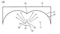
- FIGS. 1 and 2illustrate a lighting device 100 according to an embodiment of the present invention.
- the lighting device 100includes a housing 10 , a reflector 20 and a light source unit 30 .
- the housing 10has a box shape to receive the reflector 20 and an opening 11 through which a reflecting surface 21 of the reflector 20 is exposed and light is emitted.
- the housing 10can also have shapes other than the box shape shown in FIGS. 1 and 2 .
- the reflector 20is disposed within the housing 10 and has a reflecting surface 21 that reflects light emitted from the light source unit 30 .
- the reflecting surface 21includes parabola-shaped reflecting surfaces 21 a and 21 b .
- the reflecting surface 21can have other shapes based on the structure of the lighting device 100 .
- the parabola-shaped reflecting surfaces 21 a and 21 bintersect to form a boundary 22 that is disposed in a longitudinal direction of the lighting device 100 and that vertically overlaps the light source unit 30 .
- the material and color of the reflector 20can be varied to achieve a specific illumination of the lighting device 100 .
- the reflector 20can be formed of a white material having a high reflecting efficiency or be coated with silver (Ag) or aluminum (Al).
- the light source unit 30can be held and placed within the housing 10 via socket parts that interact and connect with terminals of the light source unit 30 .
- FIG. 2illustrates a single socket part 42 (another socket part on the opposite side of the light source 30 is not shown in FIG. 2 ).
- FIGS. 4-7illustrate the socket parts and connection terminals in more detail.
- FIG. 4illustrates sockets parts 41 and 42 and connection terminals 36 and 37 in an exploded view.
- FIG. 5illustrates the socket parts and connection terminals being connected together.
- the socket parts 41 and 42are connected to inner surfaces of the housing 10 according to one embodiment of the present invention.
- both ends of the light source unit 30include the first and second connection terminals 36 and 37 that interact and couple with the first and second socket parts 41 and 42 disposed on the inner surfaces of the housing 10 .
- the first and second connection terminals 36 and 37 coupled to the first and second socket parts 41 and 42support and fix the light source unit 30 .
- the first and second connection terminals 36 and 37respectively receive power from the first and second socket parts 41 and 42 so as to provide power to the light source 30 .
- the first and second socket parts 41 and 42 coupled to the first and second connection terminals 36 and 37can be referred to as first and second coupling parts.
- at least one of the first and second coupling partscan include a control part that receives a driving signal to control and drive the light source unit 30 . That is, the control part controls light emitting diodes 31 of the light source 30 to selectively emit light having a desired color, and adjusts the brightness and colors of the light emitting diodes 31 . As such, the control part controls the light emitting diodes 31 installed on the light source unit 30 to provide various illuminations. Also, when the light source unit 30 reaches its service life or is broken, the light source unit 30 can be easily replaced by removing the first and second connection terminals 36 and 37 from the first and second socket parts 41 and 42 .
- FIGS. 6 and 7illustrate the above-described coupling mechanisms.
- a shape of the first connection terminal 36can be different from the shape of the second connection terminal 37
- the shape of the first socket part 41can be different from the shape of the second socket part 42 .
- the light source unit 30can be accurately coupled to the first and second socket parts 41 and 42 without mismatching.
- the first connection terminal 36includes a block portion 36 a and a protrusion portion 36 b protruding to the lower side of the block portion 36 a , and the block portion 36 a is integrally formed with the protrusion portion 36 b .
- the first socket part 41has a shape corresponding to the first connection terminal 36 , and the protrusion portion 36 b is inserted into an insertion portion disposed in the first socket part 41 .
- a through hole 41 ais disposed in the insertion portion, and the protrusion portion 36 b passes through the through hole 41 a .
- the insertion portionis provided with an insertion recess 41 b
- the protrusion portion 36 bis disposed in the insertion recess 41 b .
- the second connection terminal 37can also include only a block portion 37 a , and the second socket part 42 can have a shape corresponding to the second connection terminal 37 .
- the second connection terminal 37can be inserted and coupled to the second socket part 42 .
- the shapes of the first and second connection terminals 36 and 37 and the first and second socket part 41 and 42are not limited to the shapes shown in these figures.
- the shape of the cross section of the block portion 36 a and 37 a of the first and second connection terminals 36 and 37can have a circular, oval and polygonal shape.
- the shape of the protrusion portion 36 bcan have a circular, oval and polygonal shape.
- the first and second connection terminals 36 and 37can have the same shape, and both the first and second connection terminals 36 and 37 can include the block portion and the protrusion portion, or only include the block portion.
- the first and second connection terminals 36 and 37can include at least two pins, respectively, and the first and second socket parts 41 and 42 can have insertion openings into which the at least two pins are inserted.
- the first and second socket parts 41 and 42support and fix the light source unit 30 and supply power to the light source unit 30 .
- the light source unit 30is disposed in the middle of the opening 11 of the housing 10 in a longitudinal direction with respect to the reflector 20 .
- the light source unit 30can be disposed in the opening 11 of the housing 10 along the boundary 22 of the reflector 20 .
- the light source unit 30is supported and fixed by the first and second socket parts 41 and 42 disposed on the inner surfaces of the housing 10 .
- the light source unit 30extends in the longitudinal direction of the reflector 20 .
- the light source 30includes a body 32 having one or more inclined surfaces, light emitting recesses 33 provided to the inclined surfaces, light emitting diodes (LEDs) 31 installed on the light emitting recesses 33 , and the first and second connection terminals 36 and 37 disposed at both ends of the body 32 .
- the LEDsare semiconductor devices that convert electrical energy to light.
- the body 32may be formed of a material adapted to efficiently emit heat such as aluminum (Al), stannum (Sn), nickel (Ni), silver (Ag), copper (Cu), titanium (Ti), molybdenum (Mo), tungsten (W), gold (Au), and platinum (Pt).
- the body 32may be formed of resin.
- the body 32may be formed of a white material having a high reflecting efficiency or be coated with silver (Ag) or aluminum (Al).
- the body 32may also have a polygonal cross section, and as shown in FIG. 2 , extend in the longitudinal direction of the reflector 20 .
- the body 32has a fan-shaped cross section in FIGS. 1 to 5 , the shape of the cross section is not limited to this particular shape.
- both side surfaces of the body 32include inclined surfaces such as first and second inclined surfaces 38 and 39 toward the reflecting surface 21 of the reflector 20 . That is, both the side surfaces of the body 32 include the first and second inclined surfaces 38 and 39 that face the parabola-shaped reflecting surfaces 21 a and 21 b of the reflecting surface 21 , respectively (see also FIG. 2 ).
- the side surfaces of the body 32may be provided with one or more inclined surfaces and are not limited to the first and second inclined surfaces 38 and 39 .
- the first and second inclined surfaces 38 and 39include light emitting recesses 33 extending in the longitudinal direction of the reflector 20 .
- the depths and widths of the light emitting recesses 33can be varied according to light distribution of the light emitting diodes 31 installed on the light emitting recesses 33 .
- the depths and widths of the light emitting recesses 33may also be adjusted to prevent light from being emitted directly to the outside through the opening 11 from the light emitting diodes 31 so that light reflected by the reflecting surface 21 is emitted to the outside through the opening 11 .
- the light emitting diodes 31are installed in the light emitting recesses 33 .
- the light emitting diodes 31may be arrayed in the light emitting recesses 33 , and the number and arrangement of the light emitting diodes 31 are not limited.
- the light emitting diodes 31may also be selected among light emitting diodes which emit red, blue, green or white light. Other colors may also be used.
- light emitted from the light emitting diodes 31is directed to the reflecting surface 21 of the reflector 20 , that is, to the parabola-shaped reflecting surfaces 21 a and 21 b .
- the light emitted from the light emitting diodes 31is reflected to a user through the reflector 20 instead of being transmitted directly to the user. Accordingly, the glare from the light is reduced and soft light is provided to the user.
- a substrate(not shown) is disposed in the light emitting recesses 33 , and the light emitting diodes 31 are installed on the substrate to electrically connect the light emitting diodes 31 .
- a plurality of electrodescan be disposed in the light emitting recesses 33 so that the light emitting diodes 31 are electrically connected through the electrodes.
- a lenscan be disposed at the light emitting recesses 33 to control the distribution of light emitted from the light emitting diodes 31 .
- the light emitting recesses 33can be filled with resin to control light distribution.
- a fluorescent membermay also be added to the lens or the resin. Also, as shown in the embodiment in FIGS.
- a lower surface of the body 32includes a convex-concave portion 34 that increases the surface area of the light source unit 30 to efficiently emit heat.
- the convex-concave portion 34also extends in the longitudinal direction of the light source unit 30 in this embodiment.
- FIG. 8illustrates a perspective view of a light source unit 130 included in a lighting device according to another embodiment of the present invention.
- the light source unit 130extends in the longitudinal direction of a reflector, and includes a body 132 having first and second inclined surfaces, light emitting recesses 133 provided to the first and second inclined surfaces, light emitting diodes 131 installed on the light emitting recesses 133 , and first and second connection terminals 136 and 137 disposed at both ends of the body 132 .
- the light emitting recesses 133are disposed partially in both side surfaces of the body 132 only at positions where the light emitting diodes 131 are installed. That is, the light emitting recesses 133 are spaced apart from each other in the body 132 .
- the upper portion of the light emitting recesses 133can also have various shapes including circular, oval and polygonal shapes in a plan view.
- the light emitting diodes 131are also arrayed in the light emitting recesses 133 .
- FIG. 9is a perspective view illustrating a lighting device 200 according to another embodiment of the present invention.
- the lighting device 200includes a light source unit 230 , a reflector 220 and support units 210 .
- the support units 210have bar shapes, support the reflector 220 and the light source unit 230 , and supply power to the light source unit 230 .
- the support units 210extend from an external support member such as a ceiling disposed above the reflector 220 and receive power from an external power source such as a power supply unit (PSU) installed at the external support member.
- PSUpower supply unit
- a first end of the support unit 210is connected to the external power source, and a second end passes through the reflector 220 and connects to an upper surface of the light source unit 230 .
- the second end of the support unit 210can also be adhered through adhesive or coupled through a screw member to the upper surface of the light source unit 230 .
- a wire membercan also be disposed in the support unit 210 so that electric current can flow through the wire member. Accordingly, power can be supplied to the light source unit 230 through the support unit 210 .
- the upper surface of the light source unit 230can include a connection terminal for connecting to the support unit 210 .
- the light source unit 230can then receive power from the support unit 210 through the connection terminal.
- the support unit 210passes through the reflector 220 and supports and fixes the reflector 220 .
- the support unit 210 passing through the reflector 220can be firmly coupled to the reflector 220 through an adhesive, for example.
- a separate support membercan be connected to the reflector 220 and support the reflector 220 .
- Other connection or coupling mechanismscan also be used.
- FIG. 9illustrates two support units 210 , a single support unit or more than two support units can be provided.
- the shape of the support unit 210can be varied.
- FIG. 10is a perspective view illustrating a lighting device 200 A according to another embodiment of the present invention.
- the lighting device 200 Aincludes the light source unit 230 , the reflector 220 and the support units 210 (the same as that shown in FIG. 9 ).
- the reflector 220has a housing structure with an opening.
- inner surfaces 222 of the reflector 220include socket parts 241 that supply power to the light source unit 230 and support the light source unit 230 .
- the coupling relationship between the socket parts 241 and connection terminals of the light source unit 230and the functions thereof are the same as those of the embodiment of FIG. 1 , a detailed description is omitted.
- the support units 210 having the bar shapessupport the reflector 220 and the light source unit 230 .
- the support units 210also extend from an external support member such as a ceiling disposed above the reflector 220 , receive power from an external power source such as a PSU installed at the external support member, and supply power to the socket parts 241 of the reflector 220 .
- a first end of the support unit 210is connected to the external power source, and a second end passes through the reflector 220 and connects to an upper surface of the light source unit 230 .
- the second end of the support unit 210can also be adhered through adhesive or coupled through a screw member to the upper surface of the light source unit 230 .
- a wire membercan also be disposed in the support unit 210 so that electric current can flow through the wire member. Accordingly, power can be supplied to the light source unit 230 through the support unit 210 .
- the upper surface of the light source unit 230can also include a connection terminal for connecting to the support unit 210 .
- the light source unit 230can then receive power from the support unit 210 through the connection terminal.
- the support unit 210passes through the reflector 220 and supports and fixes the reflector 220 .
- the support unit 210 passing through the reflector 220can be firmly coupled to the reflector 220 through an adhesive, for example.
- a separate support membercan be connected to the reflector 220 and support the reflector 220 .
- Other connection or coupling mechanismscan also be used.
- FIG. 10illustrates two support units 210 , a single support unit or a plurality of support units can be provided.
- the shape of the support unit 210can be varied.
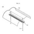
- FIG. 11is a perspective view illustrating a lighting device 300 according to yet another embodiment of the present invention.
- the lighting device 300includes a light source unit 330 , a reflector 320 and support units 310 .
- the support units 310have bar shapes, are coupled to the reflector 320 and the light source unit 330 , and support the reflector 320 and the light source unit 330 .
- poweris supplied to the light source unit 330 through the support units 310 .
- the support units 310extend from an external support member such as a bottom surface disposed under the light source unit 330 , and receive power from an external power source such as PSU installed at the external support member.
- a first end of the support unit 310is also connected to the external power source, and a second end is connected to a portion of a reflecting surface of the reflector 320 .
- the second end of the support unit 310can also be adhered through adhesive, or coupled through a screw member to the reflector 320 .
- the support units 310can also be connected to the reflector 320 passing through the light source unit 330 . Further, the support unit 310 passing through the light source unit 330 can be firmly coupled to the light source unit 330 .
- a wire membercan also be disposed in the support unit 310 so that an electric current can flow through the wire member. Accordingly, power can be supplied to the light source unit 330 through the wire member.
- FIG. 11illustrates two support units 210 , a single support unit or a plurality of support units can be provided. Furthermore, the shape of the support unit 210 can be varied.
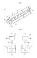
- FIG. 12is a perspective view illustrating a lighting device 300 A according to another embodiment of the present invention.
- the lighting device 300 Aincludes the light source unit 330 , the reflector 320 and support units 310 and 315 .
- the support unit 310will be referred to as a first support unit and the support unit 315 will be referred to as a second support unit.
- the first support unit 310includes a coupling part 312 coupled to a lower surface of the light source unit 330 , and a bar part 311 extending from an external support member under the light source unit 330 to supply power to the light source unit 330 .
- the second support unit 315also extends from an upper surface of the light source unit 330 to support the reflector 320 .
- FIG. 13is a schematic view illustrating the coupling relationship between the light source unit 330 and the first support unit 310 shown in FIG. 12 .
- the bar part 311 of the first support unit 310has a bar shape
- the coupling part 312has a shape corresponding to a convex-concave portion disposed at the lower surface of the light source unit 330 so that the coupling part 312 can be firmly coupled to the light source unit 330 .
- the coupling part 312 of the first support unit 310can also be used to transmit power to the light source unit 330 .
- the bar part 311 of the first support unit 310extends from an external support member such as a bottom surface disposed under the light source unit 330 .
- the bar part 311can also be used to receive power from an external power source such as a PSU installed at the external support member, and transmit the power to the light source unit 330 .
- a wire membercan also be disposed in the support unit 310 so that an electric current can flow through the wire member. Accordingly, power can be supplied to the light source unit 330 through the wire member.
- the second support unit 315extends from the upper surface of the light source unit 330 to support and fix the reflector 320 .
- a single support unit or more than two support unitscan be used. The shape of the support unit can also be varied.
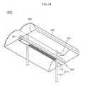
- FIG. 14is a perspective view illustrating a lighting device 300 B according to still another embodiment of the present invention.
- the lighting device 300 Bincludes the light source unit 330 , the reflector 320 , the first support unit 310 and the second support unit 315 similar to the embodiment shown in FIG. 12 .
- the first support unit 310includes the coupling part 312 coupled to the lower surface of the light source unit 330 , and the bar part 311 extending from an external support member under the light source unit 330 to supply power to the light source unit 330 .
- the second support unit 315also extends from the upper surface of the light source unit 330 to support the reflector 320 .
- the reflector 320is a housing structure with an opening. Inner surfaces 322 of the reflector 320 also include the socket parts 341 that transmit power to the light source unit 330 and support the light source unit 330 . Also, because the coupling relationship between the socket parts 341 and connection terminals of the light source unit 330 , and the functions thereof are the same as those of the embodiment of FIG. 1 , a description of these parts is omitted. The other components have already been discussed with respect to FIG. 13 . Note also that the reflector 320 in FIG. 14 does not have a box shape on an upper surface as the reflector 20 in FIG. 2 .
- the present inventionprovides several advantages.
- the light source including the LEDs according to embodiments of the present inventionhave many advantages over fluorescent and incandescent light sources such as a lower power consumption, a long service life, a rapid response speed, a stable light source and environmentally-friendly properties.
- the lighting device of embodiments of the present inventioncan also be easily disassembled and repaired, if needed.
- any reference in this specification to “one embodiment,” “an embodiment,” “example embodiment,” etc.means that a particular feature, structure or characteristic described in connection with the embodiment is included in at least one embodiment of the invention.
- the appearances of such phrases in various places in the specificationare not necessarily all referring to the same embodiment.
Landscapes
- Engineering & Computer Science (AREA)
- General Engineering & Computer Science (AREA)
- Physics & Mathematics (AREA)
- Microelectronics & Electronic Packaging (AREA)
- Optics & Photonics (AREA)
- Non-Portable Lighting Devices Or Systems Thereof (AREA)
Abstract
Description
Claims (19)
Applications Claiming Priority (6)
| Application Number | Priority Date | Filing Date | Title |
|---|---|---|---|
| KR10-2009-0052161 | 2009-06-12 | ||
| KR10-2009-0058162 | 2009-06-29 | ||
| KR1020090058160AKR20110000858A (en) | 2009-06-29 | 2009-06-29 | Lighting device |
| KR1020090058162AKR20110000860A (en) | 2009-06-29 | 2009-06-29 | Lighting device |
| KR10-2009-0058160 | 2009-06-29 | ||
| KR20090052161 | 2009-06-29 |
Publications (2)
| Publication Number | Publication Date |
|---|---|
| US20100327768A1 US20100327768A1 (en) | 2010-12-30 |
| US8376578B2true US8376578B2 (en) | 2013-02-19 |
Family
ID=43379920
Family Applications (1)
| Application Number | Title | Priority Date | Filing Date |
|---|---|---|---|
| US12/652,691Expired - Fee RelatedUS8376578B2 (en) | 2009-06-12 | 2010-01-05 | Lighting device |
Country Status (1)
| Country | Link |
|---|---|
| US (1) | US8376578B2 (en) |
Cited By (23)
| Publication number | Priority date | Publication date | Assignee | Title |
|---|---|---|---|---|
| US20130021803A1 (en)* | 2011-07-24 | 2013-01-24 | Cree, Inc. | Light fixture with co-formed plenum component |
| US20130044460A1 (en)* | 2011-08-18 | 2013-02-21 | Young Bae Jang | Backlight unit and lighting system including the same |
| US20140268720A1 (en)* | 2013-03-14 | 2014-09-18 | Cree, Inc. | Linear light fixture with interchangeable light engine unit |
| US20140268692A1 (en)* | 2013-03-14 | 2014-09-18 | Cree, Inc. | Door frame troffer |
| US20150077992A1 (en)* | 2009-08-19 | 2015-03-19 | Lg Innotek Co., Ltd. | Lighting device |
| US9188290B2 (en) | 2012-04-10 | 2015-11-17 | Cree, Inc. | Indirect linear fixture |
| USD750308S1 (en) | 2013-12-16 | 2016-02-23 | Cree, Inc. | Linear shelf light fixture |
| US9291316B2 (en) | 2012-11-08 | 2016-03-22 | Cree, Inc. | Integrated linear light engine |
| US9335041B2 (en) | 2012-05-07 | 2016-05-10 | Abl Ip Holding Llc | LED light fixture |
| USD757324S1 (en) | 2014-04-14 | 2016-05-24 | Cree, Inc. | Linear shelf light fixture with reflectors |
| US9441818B2 (en) | 2012-11-08 | 2016-09-13 | Cree, Inc. | Uplight with suspended fixture |
| US9461024B2 (en) | 2013-08-01 | 2016-10-04 | Cree, Inc. | Light emitter devices and methods for light emitting diode (LED) chips |
| US9494304B2 (en) | 2012-11-08 | 2016-11-15 | Cree, Inc. | Recessed light fixture retrofit kit |
| US9822951B2 (en) | 2010-12-06 | 2017-11-21 | Cree, Inc. | LED retrofit lens for fluorescent tube |
| US9874333B2 (en) | 2013-03-14 | 2018-01-23 | Cree, Inc. | Surface ambient wrap light fixture |
| US20180163947A1 (en)* | 2015-06-09 | 2018-06-14 | Lg Innotek Co., Ltd. | Lighting apparatus |
| US10100988B2 (en) | 2013-12-16 | 2018-10-16 | Cree, Inc. | Linear shelf light fixture with reflectors |
| US20190120440A1 (en)* | 2017-10-25 | 2019-04-25 | Green Creative, Ltd | Led light-bulb system for linear light fixtures |
| US10309627B2 (en) | 2012-11-08 | 2019-06-04 | Cree, Inc. | Light fixture retrofit kit with integrated light bar |
| US10612747B2 (en) | 2013-12-16 | 2020-04-07 | Ideal Industries Lighting Llc | Linear shelf light fixture with gap filler elements |
| US10788176B2 (en) | 2013-02-08 | 2020-09-29 | Ideal Industries Lighting Llc | Modular LED lighting system |
| US10900653B2 (en) | 2013-11-01 | 2021-01-26 | Cree Hong Kong Limited | LED mini-linear light engine |
| US11306895B2 (en)* | 2010-08-31 | 2022-04-19 | Ideal Industries Lighting Llc | Troffer-style fixture |
Families Citing this family (41)
| Publication number | Priority date | Publication date | Assignee | Title |
|---|---|---|---|---|
| US8045334B2 (en)* | 2005-10-21 | 2011-10-25 | Koninklijke Philips Electronics N.V. | Component adapted for being mounted on a substrate and a method of mounting a surface mounted device |
| DE102009010213A1 (en)* | 2009-02-23 | 2010-08-26 | Osram Gesellschaft mit beschränkter Haftung | Optoelectronic module |
| USD678597S1 (en)* | 2010-11-08 | 2013-03-19 | Cooper Technologies Company | Troffer with lens |
| US9581312B2 (en) | 2010-12-06 | 2017-02-28 | Cree, Inc. | LED light fixtures having elongated prismatic lenses |
| US9494293B2 (en) | 2010-12-06 | 2016-11-15 | Cree, Inc. | Troffer-style optical assembly |
| DE102011017161A1 (en)* | 2011-04-15 | 2012-10-18 | Cooper Crouse-Hinds Gmbh | lamp |
| US10823347B2 (en) | 2011-07-24 | 2020-11-03 | Ideal Industries Lighting Llc | Modular indirect suspended/ceiling mount fixture |
| US9423117B2 (en) | 2011-12-30 | 2016-08-23 | Cree, Inc. | LED fixture with heat pipe |
| US10544925B2 (en) | 2012-01-06 | 2020-01-28 | Ideal Industries Lighting Llc | Mounting system for retrofit light installation into existing light fixtures |
| US9777909B2 (en) | 2012-01-25 | 2017-10-03 | Mind Head Llc | Security lighting systems having offset brackets and rapidly deployable and reuseable low voltage security lighting systems |
| US9593832B2 (en)* | 2012-01-25 | 2017-03-14 | Mind Head Llc | Low voltage security lighting systems for perimeter fences |
| US8845124B2 (en) | 2012-01-25 | 2014-09-30 | David M. Beausoleil | Security lighting systems for perimeter fences |
| US9512977B2 (en)* | 2012-01-26 | 2016-12-06 | Cree, Inc. | Reduced contrast LED lighting system |
| US9777897B2 (en) | 2012-02-07 | 2017-10-03 | Cree, Inc. | Multiple panel troffer-style fixture |
| US10054274B2 (en) | 2012-03-23 | 2018-08-21 | Cree, Inc. | Direct attach ceiling-mounted solid state downlights |
| US9494294B2 (en) | 2012-03-23 | 2016-11-15 | Cree, Inc. | Modular indirect troffer |
| US9310038B2 (en) | 2012-03-23 | 2016-04-12 | Cree, Inc. | LED fixture with integrated driver circuitry |
| US9228727B2 (en) | 2012-04-05 | 2016-01-05 | Michael W. May | Lighting assembly |
| US8702265B2 (en)* | 2012-04-05 | 2014-04-22 | Michael W. May | Non-curvilinear LED luminaries |
| US9360185B2 (en) | 2012-04-09 | 2016-06-07 | Cree, Inc. | Variable beam angle directional lighting fixture assembly |
| US9874322B2 (en) | 2012-04-10 | 2018-01-23 | Cree, Inc. | Lensed troffer-style light fixture |
| US9285099B2 (en) | 2012-04-23 | 2016-03-15 | Cree, Inc. | Parabolic troffer-style light fixture |
| CN103867961B (en)* | 2012-12-07 | 2016-06-15 | 扬升照明股份有限公司 | light unit |
| US9052075B2 (en) | 2013-03-15 | 2015-06-09 | Cree, Inc. | Standardized troffer fixture |
| USD786471S1 (en) | 2013-09-06 | 2017-05-09 | Cree, Inc. | Troffer-style light fixture |
| USD807556S1 (en) | 2014-02-02 | 2018-01-09 | Cree Hong Kong Limited | Troffer-style fixture |
| USD772465S1 (en) | 2014-02-02 | 2016-11-22 | Cree Hong Kong Limited | Troffer-style fixture |
| US10451253B2 (en) | 2014-02-02 | 2019-10-22 | Ideal Industries Lighting Llc | Troffer-style fixture with LED strips |
| USD749768S1 (en) | 2014-02-06 | 2016-02-16 | Cree, Inc. | Troffer-style light fixture with sensors |
| US10527225B2 (en) | 2014-03-25 | 2020-01-07 | Ideal Industries, Llc | Frame and lens upgrade kits for lighting fixtures |
| US9648688B2 (en) | 2014-03-26 | 2017-05-09 | Mind Head Llc | Security lighting systems for perimeter security including infrared and LED lights and light intensity controllers |
| WO2015161217A1 (en) | 2014-04-18 | 2015-10-22 | May Michael W | Lighting assembly |
| WO2016032961A1 (en)* | 2014-08-25 | 2016-03-03 | Molex, Llc | Luminaire |
| US10012354B2 (en) | 2015-06-26 | 2018-07-03 | Cree, Inc. | Adjustable retrofit LED troffer |
| EP3400402B1 (en) | 2016-01-07 | 2020-12-23 | Michael W. May | Connector system for lighting assembly |
| US12385623B2 (en) | 2016-01-28 | 2025-08-12 | Korrus, Inc. | Beam-shaping lighting systems |
| US11635188B2 (en)* | 2017-03-27 | 2023-04-25 | Korrus, Inc. | Lighting systems generating visible-light emissions for dynamically emulating sky colors |
| US11585515B2 (en) | 2016-01-28 | 2023-02-21 | Korrus, Inc. | Lighting controller for emulating progression of ambient sunlight |
| US9726332B1 (en) | 2016-02-09 | 2017-08-08 | Michael W. May | Networked LED lighting system |
| US10746387B2 (en) | 2017-03-31 | 2020-08-18 | Mind Head Llc | Low voltage security lighting systems for perimeter fences having tactical glare capabilities |
| US20200022313A1 (en)* | 2018-07-19 | 2020-01-23 | Just Greens Llc | Fixtureless Lamp |
Citations (16)
| Publication number | Priority date | Publication date | Assignee | Title |
|---|---|---|---|---|
| JPH06283004A (en) | 1993-03-29 | 1994-10-07 | Toshiba Lighting & Technol Corp | Variable color lighting system |
| JPH11273430A (en) | 1998-03-26 | 1999-10-08 | Matsushita Electric Works Ltd | Luminaire for indirect lighting |
| US6238073B1 (en)* | 1998-03-13 | 2001-05-29 | Stanley Electric Co., Ltd. | Vehicle signal lighting unit |
| US20050068787A1 (en) | 2003-09-29 | 2005-03-31 | Koito Manufacturing Co., Ltd. | Vehicle headlamp |
| WO2005055328A1 (en) | 2003-12-05 | 2005-06-16 | Mitsubishi Denki Kabushiki Kaisha | Light emitting device and illumination instrument using the same |
| WO2005078338A1 (en) | 2004-02-17 | 2005-08-25 | Kelly William M | A utility lamp |
| KR20060053757A (en) | 2004-11-17 | 2006-05-22 | 삼성전자주식회사 | Lighting device with reflective collimator and image projection device employing same |
| KR200425942Y1 (en) | 2006-06-12 | 2006-09-12 | 최재민 | LED bulb for car |
| EP1847762A2 (en) | 2006-04-19 | 2007-10-24 | FARO FABBRICA APPARECCHIATURE RAZIONALI ODONTOIATRICHE S.p.A. | Compact lighting device, in particular for use in a dental lamp |
| KR20080033328A (en) | 2005-07-07 | 2008-04-16 | 마츠시다 덴코 가부시키가이샤 | Lighting device for liquid crystal panel |
| US20090002997A1 (en) | 2007-05-31 | 2009-01-01 | Koester George H | LED reflector lamp |
| KR20090010016A (en) | 2008-12-30 | 2009-01-28 | 주식회사 코스모인 | Led lighting fixtures |
| WO2009033478A1 (en) | 2007-09-14 | 2009-03-19 | Osram Gesellschaft mit beschränkter Haftung | Lighting device |
| KR20090054678A (en) | 2007-11-27 | 2009-06-01 | 엔 하이테크 주식회사 | LED polygon lamp and manufacturing method thereof |
| US7976187B2 (en)* | 2008-03-27 | 2011-07-12 | Cree, Inc. | Uniform intensity LED lighting system |
| US8052295B2 (en)* | 2006-04-28 | 2011-11-08 | Lg Display Co., Ltd. | Backlight assembly and liquid crystal display device having the same |
- 2010
- 2010-01-05USUS12/652,691patent/US8376578B2/ennot_activeExpired - Fee Related
Patent Citations (20)
| Publication number | Priority date | Publication date | Assignee | Title |
|---|---|---|---|---|
| JPH06283004A (en) | 1993-03-29 | 1994-10-07 | Toshiba Lighting & Technol Corp | Variable color lighting system |
| US6238073B1 (en)* | 1998-03-13 | 2001-05-29 | Stanley Electric Co., Ltd. | Vehicle signal lighting unit |
| JPH11273430A (en) | 1998-03-26 | 1999-10-08 | Matsushita Electric Works Ltd | Luminaire for indirect lighting |
| US20050068787A1 (en) | 2003-09-29 | 2005-03-31 | Koito Manufacturing Co., Ltd. | Vehicle headlamp |
| FR2860280A1 (en) | 2003-09-29 | 2005-04-01 | Koito Mfg Co Ltd | VEHICLE HEADLIGHT WITH PHOTOEMISSIVE ELEMENT LAMPS |
| KR20060036039A (en) | 2003-12-05 | 2006-04-27 | 미츠비시덴키 가부시키가이샤 | Light emitting device and lighting fixture using the same |
| WO2005055328A1 (en) | 2003-12-05 | 2005-06-16 | Mitsubishi Denki Kabushiki Kaisha | Light emitting device and illumination instrument using the same |
| US20060268555A1 (en) | 2004-02-17 | 2006-11-30 | Kelly William M | Utility lamp |
| WO2005078338A1 (en) | 2004-02-17 | 2005-08-25 | Kelly William M | A utility lamp |
| KR20060053757A (en) | 2004-11-17 | 2006-05-22 | 삼성전자주식회사 | Lighting device with reflective collimator and image projection device employing same |
| KR20080033328A (en) | 2005-07-07 | 2008-04-16 | 마츠시다 덴코 가부시키가이샤 | Lighting device for liquid crystal panel |
| EP1847762A2 (en) | 2006-04-19 | 2007-10-24 | FARO FABBRICA APPARECCHIATURE RAZIONALI ODONTOIATRICHE S.p.A. | Compact lighting device, in particular for use in a dental lamp |
| US8052295B2 (en)* | 2006-04-28 | 2011-11-08 | Lg Display Co., Ltd. | Backlight assembly and liquid crystal display device having the same |
| KR200425942Y1 (en) | 2006-06-12 | 2006-09-12 | 최재민 | LED bulb for car |
| US20090002997A1 (en) | 2007-05-31 | 2009-01-01 | Koester George H | LED reflector lamp |
| WO2009033478A1 (en) | 2007-09-14 | 2009-03-19 | Osram Gesellschaft mit beschränkter Haftung | Lighting device |
| US20100296266A1 (en) | 2007-09-14 | 2010-11-25 | Osram Gesellschaft mit beschränkter Haftung | Lighting Device |
| KR20090054678A (en) | 2007-11-27 | 2009-06-01 | 엔 하이테크 주식회사 | LED polygon lamp and manufacturing method thereof |
| US7976187B2 (en)* | 2008-03-27 | 2011-07-12 | Cree, Inc. | Uniform intensity LED lighting system |
| KR20090010016A (en) | 2008-12-30 | 2009-01-28 | 주식회사 코스모인 | Led lighting fixtures |
Cited By (33)
| Publication number | Priority date | Publication date | Assignee | Title |
|---|---|---|---|---|
| US9429278B2 (en)* | 2009-08-19 | 2016-08-30 | Lg Innotek Co., Ltd. | Lighting device |
| US20150077992A1 (en)* | 2009-08-19 | 2015-03-19 | Lg Innotek Co., Ltd. | Lighting device |
| US11306895B2 (en)* | 2010-08-31 | 2022-04-19 | Ideal Industries Lighting Llc | Troffer-style fixture |
| US9822951B2 (en) | 2010-12-06 | 2017-11-21 | Cree, Inc. | LED retrofit lens for fluorescent tube |
| US8752976B2 (en)* | 2011-07-24 | 2014-06-17 | Cree, Inc. | Light fixture with co-formed plenum component |
| US20130021803A1 (en)* | 2011-07-24 | 2013-01-24 | Cree, Inc. | Light fixture with co-formed plenum component |
| US20130044460A1 (en)* | 2011-08-18 | 2013-02-21 | Young Bae Jang | Backlight unit and lighting system including the same |
| US8944622B2 (en)* | 2011-08-18 | 2015-02-03 | Lg Innotek Co., Ltd. | Lighting system having reflector support and display device |
| US9188290B2 (en) | 2012-04-10 | 2015-11-17 | Cree, Inc. | Indirect linear fixture |
| US10006604B2 (en) | 2012-05-07 | 2018-06-26 | Abl Ip Holding Llc | LED light fixture |
| US9335041B2 (en) | 2012-05-07 | 2016-05-10 | Abl Ip Holding Llc | LED light fixture |
| US10309627B2 (en) | 2012-11-08 | 2019-06-04 | Cree, Inc. | Light fixture retrofit kit with integrated light bar |
| US9441818B2 (en) | 2012-11-08 | 2016-09-13 | Cree, Inc. | Uplight with suspended fixture |
| US9482396B2 (en) | 2012-11-08 | 2016-11-01 | Cree, Inc. | Integrated linear light engine |
| US9494304B2 (en) | 2012-11-08 | 2016-11-15 | Cree, Inc. | Recessed light fixture retrofit kit |
| US9291316B2 (en) | 2012-11-08 | 2016-03-22 | Cree, Inc. | Integrated linear light engine |
| US11162655B2 (en) | 2012-11-08 | 2021-11-02 | Ideal Industries Lighting Llc | Modular LED lighting system |
| US9395056B2 (en) | 2012-11-08 | 2016-07-19 | Cree, Inc. | Suspended linear fixture |
| US10788176B2 (en) | 2013-02-08 | 2020-09-29 | Ideal Industries Lighting Llc | Modular LED lighting system |
| US20140268692A1 (en)* | 2013-03-14 | 2014-09-18 | Cree, Inc. | Door frame troffer |
| US20140268720A1 (en)* | 2013-03-14 | 2014-09-18 | Cree, Inc. | Linear light fixture with interchangeable light engine unit |
| US10584860B2 (en)* | 2013-03-14 | 2020-03-10 | Ideal Industries, Llc | Linear light fixture with interchangeable light engine unit |
| US9874333B2 (en) | 2013-03-14 | 2018-01-23 | Cree, Inc. | Surface ambient wrap light fixture |
| US10648643B2 (en)* | 2013-03-14 | 2020-05-12 | Ideal Industries Lighting Llc | Door frame troffer |
| US9461024B2 (en) | 2013-08-01 | 2016-10-04 | Cree, Inc. | Light emitter devices and methods for light emitting diode (LED) chips |
| US10900653B2 (en) | 2013-11-01 | 2021-01-26 | Cree Hong Kong Limited | LED mini-linear light engine |
| US10100988B2 (en) | 2013-12-16 | 2018-10-16 | Cree, Inc. | Linear shelf light fixture with reflectors |
| US10612747B2 (en) | 2013-12-16 | 2020-04-07 | Ideal Industries Lighting Llc | Linear shelf light fixture with gap filler elements |
| USD750308S1 (en) | 2013-12-16 | 2016-02-23 | Cree, Inc. | Linear shelf light fixture |
| USD757324S1 (en) | 2014-04-14 | 2016-05-24 | Cree, Inc. | Linear shelf light fixture with reflectors |
| US10539300B2 (en)* | 2015-06-09 | 2020-01-21 | Lg Innotek Co., Ltd. | Lighting apparatus |
| US20180163947A1 (en)* | 2015-06-09 | 2018-06-14 | Lg Innotek Co., Ltd. | Lighting apparatus |
| US20190120440A1 (en)* | 2017-10-25 | 2019-04-25 | Green Creative, Ltd | Led light-bulb system for linear light fixtures |
Also Published As
| Publication number | Publication date |
|---|---|
| US20100327768A1 (en) | 2010-12-30 |
Similar Documents
| Publication | Publication Date | Title |
|---|---|---|
| US8376578B2 (en) | Lighting device | |
| EP2270390B1 (en) | Lighting device | |
| JP5806767B2 (en) | Lighting device | |
| JP5623814B2 (en) | Lighting device | |
| US8393757B2 (en) | Light-bulb type LED lamp and illumination apparatus | |
| KR101049162B1 (en) | Straight LED Lamp Assembly | |
| KR101349843B1 (en) | Lighting apparatus | |
| KR100982450B1 (en) | Led illumination lamp | |
| JP2012204187A (en) | Lamp and lighting fixture | |
| JP2004030929A (en) | LED device and LED lighting device | |
| JP2014035826A (en) | Light source apparatus and lighting apparatus | |
| CN104279442A (en) | Light emitting module and lighting device | |
| KR20110083900A (en) | LED fluorescent lamp improves luminous efficiency | |
| KR101797488B1 (en) | Lighting device | |
| JP2015061067A (en) | Light-emitting module and lighting device | |
| KR20110000859A (en) | Lighting device | |
| KR101873551B1 (en) | Illumination system | |
| JP5830675B2 (en) | lighting equipment | |
| KR101055767B1 (en) | LED lighting | |
| CN207099436U (en) | An integrated LED spotlight | |
| KR20130012673A (en) | Lighting device and lamp body of the same | |
| CN201462684U (en) | Led lamp tube | |
| JP2012099456A (en) | Lighting device | |
| CN101749650A (en) | LED (light-emitting diode) lamp tube | |
| KR20110000860A (en) | Lighting device |
Legal Events
| Date | Code | Title | Description |
|---|---|---|---|
| AS | Assignment | Owner name:LG INNOTEK CO., LTD, KOREA, REPUBLIC OF Free format text:ASSIGNMENT OF ASSIGNORS INTEREST;ASSIGNORS:KONG, KYUNG IL;KIM, HWA YOUNG;REEL/FRAME:024032/0084 Effective date:20091221 | |
| FEPP | Fee payment procedure | Free format text:PAYOR NUMBER ASSIGNED (ORIGINAL EVENT CODE: ASPN); ENTITY STATUS OF PATENT OWNER: LARGE ENTITY | |
| STCF | Information on status: patent grant | Free format text:PATENTED CASE | |
| CC | Certificate of correction | ||
| FPAY | Fee payment | Year of fee payment:4 | |
| MAFP | Maintenance fee payment | Free format text:PAYMENT OF MAINTENANCE FEE, 8TH YEAR, LARGE ENTITY (ORIGINAL EVENT CODE: M1552); ENTITY STATUS OF PATENT OWNER: LARGE ENTITY Year of fee payment:8 | |
| AS | Assignment | Owner name:SUZHOU LEKIN SEMICONDUCTOR CO., LTD., CHINA Free format text:ASSIGNMENT OF ASSIGNORS INTEREST;ASSIGNOR:LG INNOTEK CO., LTD.;REEL/FRAME:056366/0335 Effective date:20210520 | |
| FEPP | Fee payment procedure | Free format text:MAINTENANCE FEE REMINDER MAILED (ORIGINAL EVENT CODE: REM.); ENTITY STATUS OF PATENT OWNER: LARGE ENTITY | |
| LAPS | Lapse for failure to pay maintenance fees | Free format text:PATENT EXPIRED FOR FAILURE TO PAY MAINTENANCE FEES (ORIGINAL EVENT CODE: EXP.); ENTITY STATUS OF PATENT OWNER: LARGE ENTITY | |
| STCH | Information on status: patent discontinuation | Free format text:PATENT EXPIRED DUE TO NONPAYMENT OF MAINTENANCE FEES UNDER 37 CFR 1.362 | |
| FP | Lapsed due to failure to pay maintenance fee | Effective date:20250219 |