US8376428B2 - Integrated gripper for workpiece transfer - Google Patents
Integrated gripper for workpiece transferDownload PDFInfo
- Publication number
- US8376428B2 US8376428B2US11/881,088US88108807AUS8376428B2US 8376428 B2US8376428 B2US 8376428B2US 88108807 AUS88108807 AUS 88108807AUS 8376428 B2US8376428 B2US 8376428B2
- Authority
- US
- United States
- Prior art keywords
- gripper
- reticle
- edge
- gripping
- handler
- Prior art date
- Legal status (The legal status is an assumption and is not a legal conclusion. Google has not performed a legal analysis and makes no representation as to the accuracy of the status listed.)
- Active, expires
Links
Images


Classifications
- B—PERFORMING OPERATIONS; TRANSPORTING
- B25—HAND TOOLS; PORTABLE POWER-DRIVEN TOOLS; MANIPULATORS
- B25J—MANIPULATORS; CHAMBERS PROVIDED WITH MANIPULATION DEVICES
- B25J15/00—Gripping heads and other end effectors
- B25J15/0014—Gripping heads and other end effectors having fork, comb or plate shaped means for engaging the lower surface on a object to be transported
- B—PERFORMING OPERATIONS; TRANSPORTING
- B25—HAND TOOLS; PORTABLE POWER-DRIVEN TOOLS; MANIPULATORS
- B25J—MANIPULATORS; CHAMBERS PROVIDED WITH MANIPULATION DEVICES
- B25J15/00—Gripping heads and other end effectors
- B25J15/0052—Gripping heads and other end effectors multiple gripper units or multiple end effectors
- B—PERFORMING OPERATIONS; TRANSPORTING
- B25—HAND TOOLS; PORTABLE POWER-DRIVEN TOOLS; MANIPULATORS
- B25J—MANIPULATORS; CHAMBERS PROVIDED WITH MANIPULATION DEVICES
- B25J9/00—Programme-controlled manipulators
- H—ELECTRICITY
- H01—ELECTRIC ELEMENTS
- H01L—SEMICONDUCTOR DEVICES NOT COVERED BY CLASS H10
- H01L21/00—Processes or apparatus adapted for the manufacture or treatment of semiconductor or solid state devices or of parts thereof
- H01L21/67—Apparatus specially adapted for handling semiconductor or electric solid state devices during manufacture or treatment thereof; Apparatus specially adapted for handling wafers during manufacture or treatment of semiconductor or electric solid state devices or components ; Apparatus not specifically provided for elsewhere
- H01L21/683—Apparatus specially adapted for handling semiconductor or electric solid state devices during manufacture or treatment thereof; Apparatus specially adapted for handling wafers during manufacture or treatment of semiconductor or electric solid state devices or components ; Apparatus not specifically provided for elsewhere for supporting or gripping
- H01L21/687—Apparatus specially adapted for handling semiconductor or electric solid state devices during manufacture or treatment thereof; Apparatus specially adapted for handling wafers during manufacture or treatment of semiconductor or electric solid state devices or components ; Apparatus not specifically provided for elsewhere for supporting or gripping using mechanical means, e.g. chucks, clamps or pinches
- H01L21/68707—Apparatus specially adapted for handling semiconductor or electric solid state devices during manufacture or treatment thereof; Apparatus specially adapted for handling wafers during manufacture or treatment of semiconductor or electric solid state devices or components ; Apparatus not specifically provided for elsewhere for supporting or gripping using mechanical means, e.g. chucks, clamps or pinches the wafers being placed on a robot blade, or gripped by a gripper for conveyance
- Y—GENERAL TAGGING OF NEW TECHNOLOGICAL DEVELOPMENTS; GENERAL TAGGING OF CROSS-SECTIONAL TECHNOLOGIES SPANNING OVER SEVERAL SECTIONS OF THE IPC; TECHNICAL SUBJECTS COVERED BY FORMER USPC CROSS-REFERENCE ART COLLECTIONS [XRACs] AND DIGESTS
- Y10—TECHNICAL SUBJECTS COVERED BY FORMER USPC
- Y10S—TECHNICAL SUBJECTS COVERED BY FORMER USPC CROSS-REFERENCE ART COLLECTIONS [XRACs] AND DIGESTS
- Y10S901/00—Robots
- Y10S901/30—End effector
- Y10S901/31—Gripping jaw
Definitions
- the present inventionrelates to apparatuses and methods to transfer objects, and more particularly to an integrated grip arm for moving workpieces, such as semiconductor wafers, reticles or carrier boxes.
- Robot assembliesare an important component in automation, especially in manufacturing facilities and manufacturing equipments.
- robot armsare used to handle semiconductor wafers, flat panel display, LCD, reticles, masks, or carrier boxes.
- robotcan be used to transport workpieces, typically stored in carrier boxes, from one location to another location, from one equipment to another equipment.
- a robotis typically used to remove the workpieces from the carrier boxes, and then loaded into a loadlock.
- Another robotcan be used to move the workpiece from the loadlock into a processing chamber, and from one processing chamber to another processing chamber.
- the processing systemcould be a deposition system, an etch system, a lithography system, a metrology system, an inspection system, an implantation system, a treatment system, or any workpiece processing system.
- supplemental equipmentsuch as a stocker, designed for storing the workpieces until needed, or a sorter, designed for sorting the workpieces into certain desirable order.
- a robotis typically used to remove the workpieces from the carrier boxes, and then loaded into a loadlock.
- Another robotcan be used to move the workpiece from the loadlock into a storage chamber, where the workpieces are stored without the original carrier boxes.
- box stocker systemthe workpieces are stored together with the carrier boxes, without the need for removing them out of the carrier boxes.
- robot armsfor handling different workpieces.
- semiconductor waferscan be handled from the backside, thus a typical robot arm has an end effector to support the wafer.
- the waferusually rests on the end effector, held by either gravity of vacuum suction.
- backside handlingis not advisable since it might cause damage.
- grippersare typically used to handle reticles at the edge.
- robots with dual end effectorshave been employed to transfer semiconductor wafers.
- the two ends of the dual end effectorare similar, allowing the transfer of two identical wafers.
- Reticles and reticle carrier boxeshas few standards, especially for automation handling, perhaps because of the variety of reticle sizes used in the fabrication facility. And partly because of this lack of standards, many designs for reticles, containers, and boxes are in use in the facility. Reticle handling thus includes special fixtures or cassettes, and typically requires different reticle end-effector and clearances, resulting in multiple, custom end-effector, grippers and automation designs.
- One reticle handling mechanismincludes switchable arms with a docking station to store various kind of grippers. Changing arm could reduce throughput, generate particle and reduce yield and reliability of robot arms.
- an integrated grip arm for transfer reticles and carrier boxesfor improving throughput, yield and reliability of transport equipment.
- the integrated grip armcomprises a plurality of grippers to accommodate a plurality of wafers, reticles and carrier boxes.
- the exemplary integrated grip armcomprises at least two gripper arm segments serving two distinct functions of workpiece movement.
- the integrated grip armis configured for servicing a reticle equipment, such as a reticle stocker, comprising an edge gripper and a fork gripper.
- the edge gripperis designed to be an integrated part of the grip arm, configured for gripping the reticle from the side edges.
- the fork gripperis configured for gripping the reticle from the top or bottom, preferably closer to the edge of the reticle.
- the integrated grip armalso can comprise a carrier gripper, configured for gripping a container box that stores the reticle.
- the integrated grip armthus can accommodate both the reticle and its container without the need for separate arms or for gripper change.
- the container boxis a carrier box, configured for transporting the reticle within the fabrication facility, from one tool to another.
- the container boxis a storage box, configured for protecting the reticle within the stocker.
- the integrated grip armis configured for servicing a wafer equipment, such as a wafer stocker, comprising an edge gripper and an end effector.
- the edge gripperis configured for gripping the wafer from the side edges.
- the end effectoris configured for holding the wafer from the bottom, either by gravity or by gripping action.
- the integrated grip armcomprises a robot with multiple articulate joints and segments.
- the robotcan be a Cartesian robot, a r, theta and z robot, or a 6-axis robot.
- the plurality of gripper arm segmentscan be rigidly attached to each other, rigidly attached to an segment of the integrated grip arm, or can be freely rotated for the selection of arm segments.
- the integrated grip armcomprises a sensor, or a controller for the selection of gripper arm segments.
- a sensorcan indicate the locations of certain reticles, wafers or containers for the integrated grip arm to select the proper gripper arm segment.
- a controllercan contain predetermined locations of certain reticles, wafers or containers and can communicate with the integrated grip arm to select the proper gripper arm segment. The controller can further communicate of the integrated grip arm about when and where to use which gripper arm segments.
- the integrated grip arm according to the present inventioncan be used in semiconductor equipment for the movement of various fabrication workpieces such as reticles, wafers, container, carrier box or storage box.
- FIG. 1shows an exemplary grip arm segment of edge gripper.
- FIG. 2shows an exemplary grip arm segment of fork gripper.
- FIG. 3shows an exemplary embodiment of the present invention integrated grip arm comprising an edge gripper and a fork gripper.
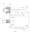
- FIG. 4shows an exemplary reticle container, reachable with a fork gripper.
- FIG. 5shows an exemplary reticle container, reachable with an edge gripper.
- FIG. 6shows an exemplary reticle container, reachable with either a fork gripper or an edge gripper.
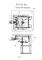
- FIG. 7shows another exemplary reticle container, reachable with an edge gripper.
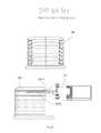
- FIG. 8shows an exemplary multiple reticle container, reachable with a fork gripper.
- the present inventiondiscloses an integrated grip arm for transfer the workpieces in a fabrication facility.
- the integrated grip armcan provide throughput, yield and reliability improvement of transport equipment.
- the integrated grip arm according to an embodiment of the present inventioncomprises a plurality of grippers to accommodate a plurality of wafers, reticles, carrier boxes and other workpieces without the need of separate arm or gripper changes.
- the integrated grip armis configured to service a system utilizing reticles such as a reticle stocker.
- reticlessuch as a reticle stocker.
- Semiconductor fabrication facilityuses non-standardized reticles and reticle containers, thus different reticle handlers exist for different designs of reticles or containers.
- an equipmentsuch as a reticle stocker, to handle a plurality of reticle designs, it requires multiple and custom reticle end-effectors and grippers with different clearances.
- the gripping mechanismis typically an edge gripping or a fork gripping mechanism.
- Reticle handlingtypically includes an edge gripper segment where the grip arm has a plurality of grippers 101 A and 101 B to grip the reticle at the edge 102 , usually at the side edge of the reticle 100 .
- the edge gripping mechanism 104includes at least two V shape arms 106 A and 106 B, approaching the reticle from the left and right sides 102 to hold the reticle.
- the edge grippertypically includes two V shape grippers at each side of the reticle.
- the gripping mechanismcan include two or four extending V shaped posts spaced apart from each other to contact the outer rim of the reticle.
- the gripping mechanism 104can move the posts 101 A and 101 B together to grip and transfer the reticle.
- FIG. 1shows an exemplary edge gripper segment, holding a reticle 100 at the side edges 102 .
- the edge grippercomprises a left 101 A and a right 101 B grippers, each having a finite length.
- the grippershave U-groove shape 103 for minimize the contact with the reticle.
- the edge grippercan move laterally to capture or release the reticle.
- FIG. 2shows an exemplary fork gripper 207 , holding a reticle 200 at two edges 202 .
- the fork grippercomprises a fork 206 A or 206 B with a top section 201 B and a bottom section 201 A for capturing the reticle 200 .
- the integrated grip arminserts the fork gripper horizontally beneath the reticle until the grooved front fork grippers are positioned to receive an edge 207 of the reticle. Then the gripper is raised to move the reticle out of the container.
- the present inventionprovides an integrated grip arm with a plurality of grippers to accommodate different designs of reticles and containers.
- the various reticle designsare particularly employed in a stocker, where different reticles and carrier boxes are stored.
- the grip arm of the present inventionis designed to interface with a plurality of reticles or carrier boxes with the use of a plurality of grippers.
- An exemplary embodiment of the present invention integrated grip arm 300is shown in FIG. 3 , comprising two gripper arms, an edge gripper 301 and a fork gripper 302 . Other configurations such as two edge grippers or two fork grippers are also possible.
- the gripperscan also in the form of multiple different reticle gripping tool, fixedly or rotatingly mounted on the robot arm.
- the gripperscan also be in the form of carrier box gripping tools.
- the multiple grippersare mounted on an arm segment 310 , or an end effector of the robot arm.
- a fork gripper mechanismcan use gravity to secure the reticle.
- the fork grippercan be static dissipative and has slender fork which are configured for insertion into slots to retrieve the reticle.
- gripperincludes mechanical grippers which are activated to grip the reticles.
- the grippercan grip the reticles mechanically and can hold the reticles with a traylike configuration with a recess for capturing the reticles.
- the grippercan also have a locking part and a gripping part.
- the grippercan contact the reticles at limited areas, such as on reticle edges, near the reticle edge, or on the chamfered edge, thus the grip arm provides minimum particle generation to protect pattern geometry of the reticles, and minimizes operator interaction to prevent reticle mishandling, and damage, plus including process control to prevent the mishandling of reticles.
- the grip armalso avoids contact with vertical edges of the reticle.
- the gripperscan engage the reticle with the reticle properly positioned within the gripper. For releasing, the grippers are retracted from their engagement with the reticle.
- the gripper mechanismcan include spring-loaded mechanisms to secure or to release the reticles.
- the gripper mechanismcan include magnetic components, to release reticles by overpowering the magnetic attraction, or to temporarily energize to overcome the magnetic attraction.
- the reticle transfer systemincludes an arm assembly having a transfer arm 310 capable of rotation and translation, and a plurality of gripping mechanisms affixed to the end of the transfer arm 310 . Once the reticle has been exposed from the container, a proper gripping mechanism is selected, with rotation and translation, so that it may access the reticle and transfer it from the container.
- the present inventionprovides a reticle transfer system that automatic transfer a reticle, regardless of the reticle types, by the use of corresponding reticle grippers.
- the I/O stationopens the box, the gripper moves in with the left and right arm moving synchronized together and clamping on the reticle.
- the edge gripperclamps at the right and left side in the middle of the reticle.
- the fork grippercomes from the front and moves two upper and two lower arms synchronized together to clamp the reticle from top and downside.
- the advantage of moving the arms synchronized togetheris that the reticle can be centered.
- FIGS. 4-8show various designs of reticles and reticle carrier box. The different designs allow either an edge gripper, a fork gripper, or a combination of both.
- the carrier boxcan also accommodate one reticle or a plurality of reticles.
- FIG. 4shows a Canon Box 400 reachable with fork gripper 302 .
- FIG. 5shows an Initial Box 500 only reachable with edge gripper 301 .
- FIG. 6shows a Toppan Box 600 reachable with edge 310 and fork gripper.
- FIG. 7shows an RSP 200 Box 700 reachable with edge gripper 301 .
- FIG. 8shows a SMIF Box 800 reachable with fork gripper 302 .
- the integrated grip arms according to the present inventioncan eliminate or minimize various problems related with exchanging grippers, such as alignment problem, particle generation problem, gripper storage problem, and throughput and yield problem. Further, the system footprint can be reduced by the use of integrated grippers, eliminating the need for gripper storage.
- the integrated grip armis preferably designed so that one gripper does not interfere with other gripper, especially during pickup or placing operations.
- the gripperscan grip the workpieces at different planes, or the grippers are separated by a large angle (preferably 70 to 170 degrees).
- the gripperscan move (rotating, linear, or swiveling) independently with respect to each other.
- the arm segment holding the gripperscan also movable (rotating, linear, or swiveling) to help moving one gripper out of the way of the other gripper.
- a robot having an integrated grip armis provided in a stocker, interfacing a storage area with a loadlock area.
- the robotserves to load and unload the various reticles into the storage area using different grippers for different reticles.
- the different grippersare designed to be rigidly or rotationally attached to the robot arm, with any desired electrical, pneumatic or mechanical connections between the associated components and the robot arm.
- the robotcan have two or more degrees of freedom, such as an Z axis motion and yaw and roll motion of the robot arm.
- the robotmay include additional degrees of freedom such as tilting with respect to the Z-axis, axial rotation, or roll, of segments of the arm, thus provide a robot arm with six degrees of freedom.
- a number of conventional drive motorssuch as a stepper or brushless motor, drive the robot arm assembly.
- the gripping mechanismsare mounted to a distal end of the arm assemble so that the arm and gripping mechanisms may move separately and simultaneously.
- the controllercontrols the movement, rotation and translation, of the robot arm and gripping mechanisms so that one gripping mechanism is properly positioned to grip and transfer the correct reticle.
- the multiple functions of the robot armwhich is provided with different grippers, provide the capability to handle different reticle designs in an efficient manner.
- the integrated grip armis configured for gripping a container box, such as a carrier box or a storage box.
- a container boxsuch as a carrier box or a storage box.
- Reticlesare conventionally handled in protective containers, such as carrier boxes or storage boxes. The handling of the reticles is typically performed in a clean environment when and where the reticles are transferred from the protective containers.
- a containertypically includes a plurality of reticles stacked inside the container.
- the containerWhen ready for processing or storage, the container is docked with an interface door of a clean environment.
- the interface dooris normally closed to isolate the clean environment conditions, and can be opened after the container is in the docked position.
- the interface dooralso can open the container to permit transport of the reticles inside the container to the clean environment.
- the integrated grip armcan load and unload e.g. five or more different boxes of reticles.
- the opening stations (I/O stations)are used to handle the reticle with the gripper.
- the gripperallows the loading and unloading all I/O stations, the buffer and rotation station.
- the reticlecan be rotates and flipped (2 degrees of freedom) in an inspection station with the gripper.
- the stockercan include a station for incorporate a storage container to the bare reticle.
- the robotthen provides the function of transfer the reticles from the loadlock to the station, and to transfer the reticle with storage container to the storage area.
- the different gripperscan serve to move the reticles, and serve to move the storage boxes.
- the I/O stationis loaded with a carrier box containing a plurality of reticles.
- the boxopens, preferably in an interface station for contamination isolation, and the first gripper picks the reticle from the box and places it in a protective or storage box, e.g. a semi bare box. Afterwards the gripper is switched, the semi bare box will be picked and placed in the stocker.
- the robotcan be a r, theta, z robot, or a 6 axis robot.
- Reticlescan also be transferred within SMIF pods, which include a pod door which interfaces with a docking station to provide a sealed environment in which the reticles may be transferred.
- the integrated grip armis configured to service a system utilizing wafers such as a wafer stocker.
- waferssuch as a wafer stocker.
- Semiconductor fabrication equipmentuses robots having end effectors to handle wafers from the bottom.
- wafer stockercan store the wafers in various positions, with very close pitch for high density storage with low footprint.
- wafer handlersexist for different designs of wafer stockers and its interfaces.
- the gripper of the integrated grip armcan be adjustable between a horizontal and a vertical position.
- the grippercan move a vertically stored wafer article into a horizontal position and vice versa.
- conventional storage systemse.g. wafer containers, FOUPs, buffer station, etc.
- Storing wafers in the vertical positioncan be arranged for higher density.
- a first grippercomprises at least two grip elements, spanning a circular arc of more than 180°.
- the gripperpicks up the wafers only at its edges.
- the grippersurround the wafer to more than half of the circle, thus can hold the wafer essentially due to the force of gravity, e.g. the gripper does not need a strong clamping mechanism to grip the wafer. This reduces the possible damage to the wafer.
- a second grippercomprises an end effector for picking wafers in horizontal positions.
- the second gripperis designed for transfer a wafer horizontally in and out of a FOUP.
- the integrated grip armcan comprise a handling unit with at least two free ends, at which a first and a second grippers are arranged.
- the handling unitis preferably about L-shaped, e.g. forming an angle between 70 to 10 degrees, with the first gripper swiveling around an axis of rotation, parallel and preferably coaxially to a leg of the L-shaped handling unit. This arrangement is economic and space-saving, with the two grippers operated with few actuators.
- the integrated grip armcomprises a means for selecting the proper gripper.
- the meanscan be a sensor or a controller, implemented to assist in the selection of gripper.
- the sensorcan be selection sensor, telling the grip arm to move the position so that the proper gripper is presented to the correct position to pickup or placing the workpieces.
- the sensorcan be mated sensor pair, one in the workpiece location and one in the gripper location. When the proper gripper is presented, the sensor pair agrees, and the grip arm proceeds.
- the sensor paircould be ON/OFF sensor with different designs of workpieces located at different locations. Thus only matched gripper/workpiece can generate a ON signal.
- the sensoris preferably wireless, such as RF, or IR sensors. Short range RFID sensor can also be used.
- the robot handle one gripper for one workpiecethus the selection of grippers is determined by looking at the boxes and the buffer, by using sensors, or by using controller for predetermined location.
- the robot armmay be designed to accommodate a sensor to identify different reticle designs, so that the robot arm can select properly the right gripper.
- sensorscan indicate the type of reticle, and thus the proper gripper mechanism.
- the selection meanscan be implemented with a controller.
- the locations of various designs of workpiecescan be pre-programmed, and thus the grip arm, when asked to pickup a workpiece from a location, can select the proper gripper for the task.
- the timing of workpiece handlingcan also be pre-programmed, thus the grip arm knows the proper gripper at a certain time.
- certain I/O stationsare dedicated to certain types of reticles. When the reticle is removed from a certain I/O station, this information can be communicated to the robot arm so that the robot arm can select the proper gripper mechanism.
- the controllercan also employ a try-out methodology, where each gripper is tested in turn, and the proper gripper can be selected when the two designs (workpiece's design and gripper's design) matched.
- the designs for different workpiece holders and grippersare preferably distinct to facilitate the mating effort.
Landscapes
- Engineering & Computer Science (AREA)
- Robotics (AREA)
- Mechanical Engineering (AREA)
- Physics & Mathematics (AREA)
- Condensed Matter Physics & Semiconductors (AREA)
- General Physics & Mathematics (AREA)
- Manufacturing & Machinery (AREA)
- Computer Hardware Design (AREA)
- Microelectronics & Electronic Packaging (AREA)
- Power Engineering (AREA)
- Container, Conveyance, Adherence, Positioning, Of Wafer (AREA)
- Exposure Of Semiconductors, Excluding Electron Or Ion Beam Exposure (AREA)
Abstract
Description
Claims (11)
Priority Applications (4)
| Application Number | Priority Date | Filing Date | Title |
|---|---|---|---|
| US11/881,088US8376428B2 (en) | 2006-11-15 | 2007-07-25 | Integrated gripper for workpiece transfer |
| PCT/IB2007/054654WO2008059454A2 (en) | 2006-11-15 | 2007-11-15 | Integrated gripper for workpiece transfer |
| US13/740,257US8651539B1 (en) | 2006-11-15 | 2013-01-13 | Integrated gripper for workpiece transfer |
| US14/181,707US9701024B2 (en) | 2006-11-15 | 2014-02-16 | Integrated gripper for workpiece transfer |
Applications Claiming Priority (2)
| Application Number | Priority Date | Filing Date | Title |
|---|---|---|---|
| US85920006P | 2006-11-15 | 2006-11-15 | |
| US11/881,088US8376428B2 (en) | 2006-11-15 | 2007-07-25 | Integrated gripper for workpiece transfer |
Related Child Applications (1)
| Application Number | Title | Priority Date | Filing Date |
|---|---|---|---|
| US13/740,257ContinuationUS8651539B1 (en) | 2006-11-15 | 2013-01-13 | Integrated gripper for workpiece transfer |
Publications (2)
| Publication Number | Publication Date |
|---|---|
| US20080131239A1 US20080131239A1 (en) | 2008-06-05 |
| US8376428B2true US8376428B2 (en) | 2013-02-19 |
Family
ID=39325634
Family Applications (3)
| Application Number | Title | Priority Date | Filing Date |
|---|---|---|---|
| US11/881,088Active2031-08-17US8376428B2 (en) | 2006-11-15 | 2007-07-25 | Integrated gripper for workpiece transfer |
| US13/740,257ActiveUS8651539B1 (en) | 2006-11-15 | 2013-01-13 | Integrated gripper for workpiece transfer |
| US14/181,707Expired - Fee RelatedUS9701024B2 (en) | 2006-11-15 | 2014-02-16 | Integrated gripper for workpiece transfer |
Family Applications After (2)
| Application Number | Title | Priority Date | Filing Date |
|---|---|---|---|
| US13/740,257ActiveUS8651539B1 (en) | 2006-11-15 | 2013-01-13 | Integrated gripper for workpiece transfer |
| US14/181,707Expired - Fee RelatedUS9701024B2 (en) | 2006-11-15 | 2014-02-16 | Integrated gripper for workpiece transfer |
Country Status (2)
| Country | Link |
|---|---|
| US (3) | US8376428B2 (en) |
| WO (1) | WO2008059454A2 (en) |
Cited By (7)
| Publication number | Priority date | Publication date | Assignee | Title |
|---|---|---|---|---|
| US8651539B1 (en)* | 2006-11-15 | 2014-02-18 | Dynamic Micro System | Integrated gripper for workpiece transfer |
| US9618857B2 (en)* | 2015-02-28 | 2017-04-11 | Kla-Tencor Corporation | End effectors and reticle handling at a high throughput |
| US10639800B2 (en)* | 2018-07-11 | 2020-05-05 | Amazon Technologies, Inc. | Robotic-arm end effector configured to engage a plurality of storage containers, and method of using the same |
| US11020852B2 (en) | 2017-10-05 | 2021-06-01 | Brooks Automation, Inc. | Substrate transport apparatus with independent accessory feedthrough |
| US20220073287A1 (en)* | 2018-10-08 | 2022-03-10 | Becton Dickinson Rowa Germany Gmbh | Operating device for placing or retrieving bottle-like piece goods |
| US11365069B2 (en)* | 2018-12-21 | 2022-06-21 | Semes Co., Ltd. | Reversing unit and substrate treating apparatus including the same |
| US20250256408A1 (en)* | 2022-08-22 | 2025-08-14 | Aesculap Ag | Handling tool for medical equipment |
Families Citing this family (11)
| Publication number | Priority date | Publication date | Assignee | Title |
|---|---|---|---|---|
| KR100771475B1 (en)* | 2006-10-04 | 2007-10-30 | (주)테크윙 | Test Tray Feeder for Side Docking Test Handler and Side Docking Test Handler |
| US7924159B2 (en)* | 2008-01-30 | 2011-04-12 | Axcelis Technologies Inc. | Remote wafer presence detection with passive RFID |
| ITPD20110212A1 (en)* | 2011-06-24 | 2012-12-25 | Rea Robotics Srl | EQUIPMENT FOR HANDLING SLABS AND REINFORCEMENT NETWORKS, PARTICULARLY FOR THE CONSTRUCTION OF PREFABRICATED PANELS FOR BUILDING |
| BR112014009754B1 (en)* | 2011-10-24 | 2020-12-29 | Remedi Technology Holdings, Llc | grouping module and method for grouping packages |
| US9431282B2 (en)* | 2011-12-27 | 2016-08-30 | Rudolph Technologies, Inc. | Wafer inversion mechanism |
| CN106672325B (en)* | 2017-02-21 | 2022-08-16 | 苏州优备精密智能装备股份有限公司 | Box supporting equipment |
| JP6994411B2 (en)* | 2018-02-28 | 2022-01-14 | オークマ株式会社 | Machine tool system |
| CN109502332A (en)* | 2018-11-23 | 2019-03-22 | 晋城鸿刃科技有限公司 | Blanking device |
| JP7003945B2 (en)* | 2019-02-22 | 2022-02-10 | 村田機械株式会社 | Transfer device and stacker crane |
| DE102019211245A1 (en)* | 2019-07-29 | 2021-02-04 | Kuka Deutschland Gmbh | Transport container gripper |
| WO2025101783A1 (en)* | 2023-11-07 | 2025-05-15 | Versabuilt, Inc. | Dual-function robotic gripper for workpiece and workholding handling in cnc processing sequences |
Citations (23)
| Publication number | Priority date | Publication date | Assignee | Title |
|---|---|---|---|---|
| US3968885A (en)* | 1973-06-29 | 1976-07-13 | International Business Machines Corporation | Method and apparatus for handling workpieces |
| US4410209A (en)* | 1982-03-11 | 1983-10-18 | Trapani Silvio P | Wafer-handling tool |
| US4452480A (en)* | 1981-12-21 | 1984-06-05 | International Jensen Incorporated | Record handling device |
| US4778332A (en)* | 1987-02-09 | 1988-10-18 | The Perkin-Elmer Corporation | Wafer flip apparatus |
| US4848814A (en)* | 1986-10-31 | 1989-07-18 | Nihon Shinku Gijutsu Kabushiki Kaisha | Wafer transfer hand |
| US5192106A (en)* | 1990-06-04 | 1993-03-09 | I.A.F. Enterprises, Inc. | Compact disc handling device |
| US5700046A (en)* | 1995-09-13 | 1997-12-23 | Silicon Valley Group, Inc. | Wafer gripper |
| US6077026A (en)* | 1998-03-30 | 2000-06-20 | Progressive System Technologies, Inc. | Programmable substrate support for a substrate positioning system |
| US6164899A (en)* | 1999-04-22 | 2000-12-26 | Automated Concepts, Inc. | Disk transfer apparatus |
| US20010011876A1 (en) | 2000-02-07 | 2001-08-09 | Tazmo Co., Ltd. | Substrate transfer system |
| US6368040B1 (en)* | 1998-02-18 | 2002-04-09 | Tokyo Electron Limited | Apparatus for and method of transporting substrates to be processed |
| US20020048506A1 (en)* | 2000-09-01 | 2002-04-25 | Babbs Daniel A. | Edge grip aligner with buffering capabilities |
| US6499936B2 (en)* | 2001-02-17 | 2002-12-31 | Yokogawa Electric Corporation | Transfer system |
| US6592324B2 (en)* | 2001-02-26 | 2003-07-15 | Irm, Llc | Gripper mechanism |
| US6909276B2 (en)* | 2000-06-14 | 2005-06-21 | Micron Technology, Inc. | Rotating gripper wafer flipper |
| US6991419B2 (en)* | 2001-04-16 | 2006-01-31 | Samsung Electronics Co., Ltd. | Method and apparatus for transferring a wafer |
| USD552138S1 (en)* | 2005-06-29 | 2007-10-02 | Tokyo Electron Limited | Arm transferring substrate to be processed |
| US7396199B2 (en)* | 2001-12-28 | 2008-07-08 | Dainippon Screen Mfg. Co., Ltd. | Substrate processing apparatus and substrate processing method |
| US7401828B2 (en)* | 2005-06-20 | 2008-07-22 | Lg Display Co., Ltd. | Substrate conveyance device for fabrication of liquid crystal display device |
| US7616289B2 (en)* | 2002-03-23 | 2009-11-10 | Lg Display Co., Ltd. | Apparatus for conveying liquid crystal display panel |
| US7751172B2 (en)* | 2006-10-18 | 2010-07-06 | Axcelis Technologies, Inc. | Sliding wafer release gripper/wafer peeling gripper |
| US7896602B2 (en)* | 2006-06-09 | 2011-03-01 | Lutz Rebstock | Workpiece stocker with circular configuration |
| US7900776B2 (en)* | 2003-11-16 | 2011-03-08 | Entegris, Inc. | Wafer container with door actuated wafer restraint |
Family Cites Families (16)
| Publication number | Priority date | Publication date | Assignee | Title |
|---|---|---|---|---|
| US1365227A (en)* | 1919-04-14 | 1921-01-11 | Elmer O Clark | Phonograph-record-handling device |
| US3961819A (en)* | 1975-10-24 | 1976-06-08 | Yocum Richard A | Record tool |
| US4999671A (en)* | 1986-07-11 | 1991-03-12 | Canon Kabushiki Kaisha | Reticle conveying device |
| US5749469A (en)* | 1992-05-15 | 1998-05-12 | Fluoroware, Inc. | Wafer carrier |
| US5863086A (en)* | 1994-11-21 | 1999-01-26 | Mcneilus Truck And Manufacturing, Inc. | Container holding and lifting device |
| JP3442219B2 (en) | 1996-04-01 | 2003-09-02 | 大日本スクリーン製造株式会社 | Substrate processing equipment |
| US6203617B1 (en)* | 1998-03-26 | 2001-03-20 | Tokyo Electron Limited | Conveying unit and substrate processing unit |
| US6736386B1 (en)* | 2001-04-10 | 2004-05-18 | Dupont Photomasks, Inc. | Covered photomask holder and method of using the same |
| JP3920587B2 (en)* | 2001-04-16 | 2007-05-30 | 東京エレクトロン株式会社 | Teaching method for substrate transfer means |
| JP2003302083A (en) | 2002-04-10 | 2003-10-24 | Canon Inc | Work processing method, work processing apparatus and cassette, and unit of printing apparatus |
| JP4136949B2 (en) | 2004-01-16 | 2008-08-20 | 株式会社小松製作所 | Runaway monitoring device for electric servo press |
| DE102006028057B4 (en)* | 2005-10-17 | 2017-07-20 | Dynamic Microsystems Semiconductor Equipment Gmbh | Device for storing contamination-sensitive, plate-shaped objects, in particular for storing semiconductor wafers |
| US8376428B2 (en)* | 2006-11-15 | 2013-02-19 | Dynamic Micro System Semiconductor Equipment GmbH | Integrated gripper for workpiece transfer |
| JP4979530B2 (en)* | 2007-09-28 | 2012-07-18 | 日本電産サンキョー株式会社 | Industrial robot |
| JP5838504B2 (en) | 2011-05-30 | 2016-01-06 | 株式会社ツムラ | Container cleaning system using robot |
| US9646858B2 (en)* | 2011-06-23 | 2017-05-09 | Brooks Automation, Inc. | Semiconductor cleaner systems and methods |
- 2007
- 2007-07-25USUS11/881,088patent/US8376428B2/enactiveActive
- 2007-11-15WOPCT/IB2007/054654patent/WO2008059454A2/enactiveApplication Filing
- 2013
- 2013-01-13USUS13/740,257patent/US8651539B1/enactiveActive
- 2014
- 2014-02-16USUS14/181,707patent/US9701024B2/ennot_activeExpired - Fee Related
Patent Citations (23)
| Publication number | Priority date | Publication date | Assignee | Title |
|---|---|---|---|---|
| US3968885A (en)* | 1973-06-29 | 1976-07-13 | International Business Machines Corporation | Method and apparatus for handling workpieces |
| US4452480A (en)* | 1981-12-21 | 1984-06-05 | International Jensen Incorporated | Record handling device |
| US4410209A (en)* | 1982-03-11 | 1983-10-18 | Trapani Silvio P | Wafer-handling tool |
| US4848814A (en)* | 1986-10-31 | 1989-07-18 | Nihon Shinku Gijutsu Kabushiki Kaisha | Wafer transfer hand |
| US4778332A (en)* | 1987-02-09 | 1988-10-18 | The Perkin-Elmer Corporation | Wafer flip apparatus |
| US5192106A (en)* | 1990-06-04 | 1993-03-09 | I.A.F. Enterprises, Inc. | Compact disc handling device |
| US5700046A (en)* | 1995-09-13 | 1997-12-23 | Silicon Valley Group, Inc. | Wafer gripper |
| US6368040B1 (en)* | 1998-02-18 | 2002-04-09 | Tokyo Electron Limited | Apparatus for and method of transporting substrates to be processed |
| US6077026A (en)* | 1998-03-30 | 2000-06-20 | Progressive System Technologies, Inc. | Programmable substrate support for a substrate positioning system |
| US6164899A (en)* | 1999-04-22 | 2000-12-26 | Automated Concepts, Inc. | Disk transfer apparatus |
| US20010011876A1 (en) | 2000-02-07 | 2001-08-09 | Tazmo Co., Ltd. | Substrate transfer system |
| US6909276B2 (en)* | 2000-06-14 | 2005-06-21 | Micron Technology, Inc. | Rotating gripper wafer flipper |
| US20020048506A1 (en)* | 2000-09-01 | 2002-04-25 | Babbs Daniel A. | Edge grip aligner with buffering capabilities |
| US6499936B2 (en)* | 2001-02-17 | 2002-12-31 | Yokogawa Electric Corporation | Transfer system |
| US6592324B2 (en)* | 2001-02-26 | 2003-07-15 | Irm, Llc | Gripper mechanism |
| US6991419B2 (en)* | 2001-04-16 | 2006-01-31 | Samsung Electronics Co., Ltd. | Method and apparatus for transferring a wafer |
| US7396199B2 (en)* | 2001-12-28 | 2008-07-08 | Dainippon Screen Mfg. Co., Ltd. | Substrate processing apparatus and substrate processing method |
| US7616289B2 (en)* | 2002-03-23 | 2009-11-10 | Lg Display Co., Ltd. | Apparatus for conveying liquid crystal display panel |
| US7900776B2 (en)* | 2003-11-16 | 2011-03-08 | Entegris, Inc. | Wafer container with door actuated wafer restraint |
| US7401828B2 (en)* | 2005-06-20 | 2008-07-22 | Lg Display Co., Ltd. | Substrate conveyance device for fabrication of liquid crystal display device |
| USD552138S1 (en)* | 2005-06-29 | 2007-10-02 | Tokyo Electron Limited | Arm transferring substrate to be processed |
| US7896602B2 (en)* | 2006-06-09 | 2011-03-01 | Lutz Rebstock | Workpiece stocker with circular configuration |
| US7751172B2 (en)* | 2006-10-18 | 2010-07-06 | Axcelis Technologies, Inc. | Sliding wafer release gripper/wafer peeling gripper |
Non-Patent Citations (1)
| Title |
|---|
| PCT preliminary report on patentability-PCT/IB2007/054654-dated May 28, 2009. |
Cited By (12)
| Publication number | Priority date | Publication date | Assignee | Title |
|---|---|---|---|---|
| US8651539B1 (en)* | 2006-11-15 | 2014-02-18 | Dynamic Micro System | Integrated gripper for workpiece transfer |
| US20140161572A1 (en)* | 2006-11-15 | 2014-06-12 | Dynamic Micro Systems, Semiconductor Equipment Gmb | Integrated gripper for workpiece transfer |
| US9701024B2 (en)* | 2006-11-15 | 2017-07-11 | Brooks Ccs Gmbh | Integrated gripper for workpiece transfer |
| US9618857B2 (en)* | 2015-02-28 | 2017-04-11 | Kla-Tencor Corporation | End effectors and reticle handling at a high throughput |
| US11020852B2 (en) | 2017-10-05 | 2021-06-01 | Brooks Automation, Inc. | Substrate transport apparatus with independent accessory feedthrough |
| US10639800B2 (en)* | 2018-07-11 | 2020-05-05 | Amazon Technologies, Inc. | Robotic-arm end effector configured to engage a plurality of storage containers, and method of using the same |
| GB2591347B (en)* | 2018-07-11 | 2022-09-28 | Amazon Tech Inc | Robotic-arm end effector configured to engage a plurality of storage containers, and method of using the same |
| US20220073287A1 (en)* | 2018-10-08 | 2022-03-10 | Becton Dickinson Rowa Germany Gmbh | Operating device for placing or retrieving bottle-like piece goods |
| US11713200B2 (en)* | 2018-10-08 | 2023-08-01 | Becton Dickinson Rowa Germany Gmbh | Operating device for placing or retrieving bottle-like piece goods |
| US12006164B2 (en) | 2018-10-08 | 2024-06-11 | Becton Dickinson Rowa Germany Gmbh | Operating device for placing or retrieving bottle-like piece goods |
| US11365069B2 (en)* | 2018-12-21 | 2022-06-21 | Semes Co., Ltd. | Reversing unit and substrate treating apparatus including the same |
| US20250256408A1 (en)* | 2022-08-22 | 2025-08-14 | Aesculap Ag | Handling tool for medical equipment |
Also Published As
| Publication number | Publication date |
|---|---|
| US9701024B2 (en) | 2017-07-11 |
| US20140161572A1 (en) | 2014-06-12 |
| WO2008059454A2 (en) | 2008-05-22 |
| US8651539B1 (en) | 2014-02-18 |
| US20080131239A1 (en) | 2008-06-05 |
| WO2008059454A3 (en) | 2008-07-24 |
Similar Documents
| Publication | Publication Date | Title |
|---|---|---|
| US8376428B2 (en) | Integrated gripper for workpiece transfer | |
| US6822413B2 (en) | Systems and methods incorporating an end effector with a rotatable and/or pivotable body and/or an optical sensor having a light path that extends along a length of the end effector | |
| EP2092555B1 (en) | Workpiece stocker with circular configuration | |
| US20200388523A1 (en) | Wafer aligner | |
| US9728436B2 (en) | Transfer mechanism with multiple wafer handling capability | |
| US8812150B2 (en) | Semiconductor manufacturing process modules | |
| US10672633B2 (en) | Removable compartments for workpiece stocker | |
| US20090028669A1 (en) | Removable compartments for workpiece stocker | |
| JP2002512446A (en) | Automated wafer buffer for use with wafer processing equipment | |
| EP2092556B1 (en) | Compartments for workpiece stocker | |
| EP1252079B1 (en) | Wafer transport system | |
| KR20250048284A (en) | End effector and robot with end effector | |
| US20240312821A1 (en) | Automatic teaching apparatus for semiconductor manufacturing equipment | |
| WO2024072615A1 (en) | Method and apparatus for processing a substrate in cleaning modules | |
| US20080181758A1 (en) | Microfeature workpiece transfer devices with rotational orientation sensors, and associated systems and methods | |
| EP1615735A2 (en) | Wafer carrier cleaning system | |
| JPWO2020252476A5 (en) | ||
| US6969841B2 (en) | Method and apparatus for securing microelectronic workpiece containers | |
| JP2025534280A (en) | Method and apparatus for processing a substrate in a cleaning module | |
| EP1460676A2 (en) | Reduced footprint tool for automated processing of microelectronic substrates |
Legal Events
| Date | Code | Title | Description |
|---|---|---|---|
| AS | Assignment | Owner name:DYNAMIC MICRO SYSTEMS, GERMANY Free format text:ASSIGNMENT OF ASSIGNORS INTEREST;ASSIGNOR:REBSTOCK, LUTZ;REEL/FRAME:019669/0054 Effective date:20070724 | |
| STCF | Information on status: patent grant | Free format text:PATENTED CASE | |
| FEPP | Fee payment procedure | Free format text:PAT HOLDER NO LONGER CLAIMS SMALL ENTITY STATUS, ENTITY STATUS SET TO UNDISCOUNTED (ORIGINAL EVENT CODE: STOL); ENTITY STATUS OF PATENT OWNER: LARGE ENTITY | |
| FPAY | Fee payment | Year of fee payment:4 | |
| MAFP | Maintenance fee payment | Free format text:PAYMENT OF MAINTENANCE FEE, 8TH YEAR, LARGE ENTITY (ORIGINAL EVENT CODE: M1552); ENTITY STATUS OF PATENT OWNER: LARGE ENTITY Year of fee payment:8 | |
| AS | Assignment | Owner name:BROOKS AUTOMATION US, LLC, MASSACHUSETTS Free format text:ASSIGNMENT OF ASSIGNORS INTEREST;ASSIGNOR:BROOKS AUTOMATION HOLDING, LLC;REEL/FRAME:058482/0001 Effective date:20211001 Owner name:BROOKS AUTOMATION HOLDING, LLC, MASSACHUSETTS Free format text:ASSIGNMENT OF ASSIGNORS INTEREST;ASSIGNOR:BROOKS AUTOMATION,INC;REEL/FRAME:058481/0740 Effective date:20211001 | |
| AS | Assignment | Owner name:BROOKS AUTOMATION (GERMANY) GMBH, GERMANY Free format text:SUBMISSION IS TO CORRECT AN ERROR MADE IN A PREVIOUSLY RECORDED DOCUMENT THAT ERRONEOUSLY AFFECTS THE IDENTIFIED APPLICATION(S), OR PATENT(S);ASSIGNOR:BROOKS AUTOMATION (GERMANY) GMBH;REEL/FRAME:058771/0795 Effective date:20220119 | |
| MAFP | Maintenance fee payment | Free format text:PAYMENT OF MAINTENANCE FEE, 12TH YEAR, LARGE ENTITY (ORIGINAL EVENT CODE: M1553); ENTITY STATUS OF PATENT OWNER: LARGE ENTITY Year of fee payment:12 |