US8376034B2 - Radiant coolers and methods for assembling same - Google Patents
Radiant coolers and methods for assembling sameDownload PDFInfo
- Publication number
- US8376034B2 US8376034B2US11/862,021US86202107AUS8376034B2US 8376034 B2US8376034 B2US 8376034B2US 86202107 AUS86202107 AUS 86202107AUS 8376034 B2US8376034 B2US 8376034B2
- Authority
- US
- United States
- Prior art keywords
- tube
- circumferentially
- chevron
- length
- tube cage
- Prior art date
- Legal status (The legal status is an assumption and is not a legal conclusion. Google has not performed a legal analysis and makes no representation as to the accuracy of the status listed.)
- Active, expires
Links
- 238000000034methodMethods0.000titleclaimsabstractdescription15
- 238000001816coolingMethods0.000claimsabstractdescription44
- 238000004891communicationMethods0.000claimsabstractdescription14
- 230000008878couplingEffects0.000claimsabstractdescription3
- 238000010168coupling processMethods0.000claimsabstractdescription3
- 238000005859coupling reactionMethods0.000claimsabstractdescription3
- 239000007789gasSubstances0.000description19
- 239000003570airSubstances0.000description14
- 238000000926separation methodMethods0.000description9
- IJGRMHOSHXDMSA-UHFFFAOYSA-NAtomic nitrogenChemical compoundN#NIJGRMHOSHXDMSA-UHFFFAOYSA-N0.000description8
- 238000002309gasificationMethods0.000description7
- 239000000446fuelSubstances0.000description6
- XLYOFNOQVPJJNP-UHFFFAOYSA-NwaterSubstancesOXLYOFNOQVPJJNP-UHFFFAOYSA-N0.000description6
- 238000004519manufacturing processMethods0.000description5
- 230000009467reductionEffects0.000description5
- CURLTUGMZLYLDI-UHFFFAOYSA-NCarbon dioxideChemical compoundO=C=OCURLTUGMZLYLDI-UHFFFAOYSA-N0.000description4
- QVGXLLKOCUKJST-UHFFFAOYSA-Natomic oxygenChemical compound[O]QVGXLLKOCUKJST-UHFFFAOYSA-N0.000description4
- 239000012809cooling fluidSubstances0.000description4
- 239000000463materialSubstances0.000description4
- 229910052757nitrogenInorganic materials0.000description4
- 239000001301oxygenSubstances0.000description4
- 229910052760oxygenInorganic materials0.000description4
- 238000010248power generationMethods0.000description4
- 230000008569processEffects0.000description4
- 229910002092carbon dioxideInorganic materials0.000description3
- 239000001569carbon dioxideSubstances0.000description3
- 238000002485combustion reactionMethods0.000description3
- 238000011084recoveryMethods0.000description3
- XKRFYHLGVUSROY-UHFFFAOYSA-NArgonChemical compound[Ar]XKRFYHLGVUSROY-UHFFFAOYSA-N0.000description2
- GQPLMRYTRLFLPF-UHFFFAOYSA-NNitrous OxideChemical compound[O-][N+]#NGQPLMRYTRLFLPF-UHFFFAOYSA-N0.000description2
- 238000005452bendingMethods0.000description2
- 238000010586diagramMethods0.000description2
- 239000000203mixtureSubstances0.000description2
- 238000011144upstream manufacturingMethods0.000description2
- 235000019738LimestoneNutrition0.000description1
- 229910000831SteelInorganic materials0.000description1
- 239000012080ambient airSubstances0.000description1
- 229910052786argonInorganic materials0.000description1
- -1but not limited toSubstances0.000description1
- 239000006227byproductSubstances0.000description1
- VNTLIPZTSJSULJ-UHFFFAOYSA-Nchromium molybdenumChemical compound[Cr].[Mo]VNTLIPZTSJSULJ-UHFFFAOYSA-N0.000description1
- 238000004140cleaningMethods0.000description1
- 239000003245coalSubstances0.000description1
- 239000000839emulsionSubstances0.000description1
- 239000013529heat transfer fluidSubstances0.000description1
- 239000006028limestoneSubstances0.000description1
- 239000012528membraneSubstances0.000description1
- 230000004048modificationEffects0.000description1
- 238000012986modificationMethods0.000description1
- 239000001272nitrous oxideSubstances0.000description1
- 239000002006petroleum cokeSubstances0.000description1
- 239000007787solidSubstances0.000description1
- 239000010959steelSubstances0.000description1
Images


Classifications
- F—MECHANICAL ENGINEERING; LIGHTING; HEATING; WEAPONS; BLASTING
- F28—HEAT EXCHANGE IN GENERAL
- F28D—HEAT-EXCHANGE APPARATUS, NOT PROVIDED FOR IN ANOTHER SUBCLASS, IN WHICH THE HEAT-EXCHANGE MEDIA DO NOT COME INTO DIRECT CONTACT
- F28D7/00—Heat-exchange apparatus having stationary tubular conduit assemblies for both heat-exchange media, the media being in contact with different sides of a conduit wall
- F28D7/0041—Heat-exchange apparatus having stationary tubular conduit assemblies for both heat-exchange media, the media being in contact with different sides of a conduit wall the conduits for only one medium being tubes having parts touching each other or tubes assembled in panel form
- F—MECHANICAL ENGINEERING; LIGHTING; HEATING; WEAPONS; BLASTING
- F01—MACHINES OR ENGINES IN GENERAL; ENGINE PLANTS IN GENERAL; STEAM ENGINES
- F01K—STEAM ENGINE PLANTS; STEAM ACCUMULATORS; ENGINE PLANTS NOT OTHERWISE PROVIDED FOR; ENGINES USING SPECIAL WORKING FLUIDS OR CYCLES
- F01K23/00—Plants characterised by more than one engine delivering power external to the plant, the engines being driven by different fluids
- F01K23/02—Plants characterised by more than one engine delivering power external to the plant, the engines being driven by different fluids the engine cycles being thermally coupled
- F01K23/06—Plants characterised by more than one engine delivering power external to the plant, the engines being driven by different fluids the engine cycles being thermally coupled combustion heat from one cycle heating the fluid in another cycle
- F01K23/067—Plants characterised by more than one engine delivering power external to the plant, the engines being driven by different fluids the engine cycles being thermally coupled combustion heat from one cycle heating the fluid in another cycle the combustion heat coming from a gasification or pyrolysis process, e.g. coal gasification
- F01K23/068—Plants characterised by more than one engine delivering power external to the plant, the engines being driven by different fluids the engine cycles being thermally coupled combustion heat from one cycle heating the fluid in another cycle the combustion heat coming from a gasification or pyrolysis process, e.g. coal gasification in combination with an oxygen producing plant, e.g. an air separation plant
- F—MECHANICAL ENGINEERING; LIGHTING; HEATING; WEAPONS; BLASTING
- F22—STEAM GENERATION
- F22B—METHODS OF STEAM GENERATION; STEAM BOILERS
- F22B21/00—Water-tube boilers of vertical or steeply-inclined type, i.e. the water-tube sets being arranged vertically or substantially vertically
- F22B21/02—Water-tube boilers of vertical or steeply-inclined type, i.e. the water-tube sets being arranged vertically or substantially vertically built-up from substantially-straight water tubes
- F—MECHANICAL ENGINEERING; LIGHTING; HEATING; WEAPONS; BLASTING
- F22—STEAM GENERATION
- F22B—METHODS OF STEAM GENERATION; STEAM BOILERS
- F22B21/00—Water-tube boilers of vertical or steeply-inclined type, i.e. the water-tube sets being arranged vertically or substantially vertically
- F22B21/34—Water-tube boilers of vertical or steeply-inclined type, i.e. the water-tube sets being arranged vertically or substantially vertically built-up from water tubes grouped in panel form surrounding the combustion chamber, i.e. radiation boilers
- F22B21/38—Component parts thereof, e.g. prefabricated panels
- F—MECHANICAL ENGINEERING; LIGHTING; HEATING; WEAPONS; BLASTING
- F22—STEAM GENERATION
- F22B—METHODS OF STEAM GENERATION; STEAM BOILERS
- F22B37/00—Component parts or details of steam boilers
- F22B37/02—Component parts or details of steam boilers applicable to more than one kind or type of steam boiler
- F22B37/10—Water tubes; Accessories therefor
- F22B37/14—Supply mains, e.g. rising mains, down-comers, in connection with water tubes
- F22B37/145—Flag-shaped panels built-up from tubes, e.g. from U-shaped tubes
- F—MECHANICAL ENGINEERING; LIGHTING; HEATING; WEAPONS; BLASTING
- F28—HEAT EXCHANGE IN GENERAL
- F28D—HEAT-EXCHANGE APPARATUS, NOT PROVIDED FOR IN ANOTHER SUBCLASS, IN WHICH THE HEAT-EXCHANGE MEDIA DO NOT COME INTO DIRECT CONTACT
- F28D7/00—Heat-exchange apparatus having stationary tubular conduit assemblies for both heat-exchange media, the media being in contact with different sides of a conduit wall
- F28D7/16—Heat-exchange apparatus having stationary tubular conduit assemblies for both heat-exchange media, the media being in contact with different sides of a conduit wall the conduits being arranged in parallel spaced relation
- F28D7/163—Heat-exchange apparatus having stationary tubular conduit assemblies for both heat-exchange media, the media being in contact with different sides of a conduit wall the conduits being arranged in parallel spaced relation with conduit assemblies having a particular shape, e.g. square or annular; with assemblies of conduits having different geometrical features; with multiple groups of conduits connected in series or parallel and arranged inside common casing
- F28D7/1669—Heat-exchange apparatus having stationary tubular conduit assemblies for both heat-exchange media, the media being in contact with different sides of a conduit wall the conduits being arranged in parallel spaced relation with conduit assemblies having a particular shape, e.g. square or annular; with assemblies of conduits having different geometrical features; with multiple groups of conduits connected in series or parallel and arranged inside common casing the conduit assemblies having an annular shape; the conduits being assembled around a central distribution tube
- F—MECHANICAL ENGINEERING; LIGHTING; HEATING; WEAPONS; BLASTING
- F28—HEAT EXCHANGE IN GENERAL
- F28D—HEAT-EXCHANGE APPARATUS, NOT PROVIDED FOR IN ANOTHER SUBCLASS, IN WHICH THE HEAT-EXCHANGE MEDIA DO NOT COME INTO DIRECT CONTACT
- F28D21/00—Heat-exchange apparatus not covered by any of the groups F28D1/00 - F28D20/00
- F28D2021/0019—Other heat exchangers for particular applications; Heat exchange systems not otherwise provided for
- F28D2021/0075—Other heat exchangers for particular applications; Heat exchange systems not otherwise provided for for syngas or cracked gas cooling systems
- Y—GENERAL TAGGING OF NEW TECHNOLOGICAL DEVELOPMENTS; GENERAL TAGGING OF CROSS-SECTIONAL TECHNOLOGIES SPANNING OVER SEVERAL SECTIONS OF THE IPC; TECHNICAL SUBJECTS COVERED BY FORMER USPC CROSS-REFERENCE ART COLLECTIONS [XRACs] AND DIGESTS
- Y02—TECHNOLOGIES OR APPLICATIONS FOR MITIGATION OR ADAPTATION AGAINST CLIMATE CHANGE
- Y02E—REDUCTION OF GREENHOUSE GAS [GHG] EMISSIONS, RELATED TO ENERGY GENERATION, TRANSMISSION OR DISTRIBUTION
- Y02E20/00—Combustion technologies with mitigation potential
- Y02E20/16—Combined cycle power plant [CCPP], or combined cycle gas turbine [CCGT]
- Y02E20/18—Integrated gasification combined cycle [IGCC], e.g. combined with carbon capture and storage [CCS]
- Y—GENERAL TAGGING OF NEW TECHNOLOGICAL DEVELOPMENTS; GENERAL TAGGING OF CROSS-SECTIONAL TECHNOLOGIES SPANNING OVER SEVERAL SECTIONS OF THE IPC; TECHNICAL SUBJECTS COVERED BY FORMER USPC CROSS-REFERENCE ART COLLECTIONS [XRACs] AND DIGESTS
- Y10—TECHNICAL SUBJECTS COVERED BY FORMER USPC
- Y10T—TECHNICAL SUBJECTS COVERED BY FORMER US CLASSIFICATION
- Y10T29/00—Metal working
- Y10T29/49—Method of mechanical manufacture
- Y10T29/4935—Heat exchanger or boiler making
Definitions
- This inventionrelates generally to gasification systems, and more specifically to a radiant cooler.
- At least some known gasification systemsare integrated with at least one power-producing turbine system.
- at least some known gasifiersconvert a mixture of fuel, air or oxygen, and/or steam into an output of partially combusted gas, sometimes referred to as “syngas.”
- the hot syngasmay be supplied to a combustor of a gas turbine engine, which powers a generator that supplies electrical power to a power grid.
- Exhaust from at least some known gas turbine enginesis supplied to a heat recovery steam generator that generates steam for driving a steam turbine. Power generated by the steam turbine also drives an electrical generator that provides electrical power to the power grid.
- At least some known gasification systemsuse a separate gasifier that, in combination with the syngas cooler, facilitates gasifying feedstocks, recovering heat, and removing solids from the syngas to make the syngas more useable by other systems.
- at least some known syngas coolersinclude a plurality of platens and a tube wall that defines a heat exchange surface area that facilitates transferring heat from the flow of syngas to a heat transfer fluid channeled within each platen and/or the tube wall.
- the plurality of platens in such syngas coolersare substantially circumscribed by the tube wall, which is further surrounded by a cooler vessel shell.
- Known tube wallsare designed to be gas-tight to retain syngas within the tube wall such that syngas contacts the tube wall rather than the cooler vessel shell.
- At least some known syngas coolersinclude a plurality of downcomers that extend generally axially within a space defined by the tube wall and the vessel shell.
- the diameter of the vessel shell of such coolersis sized to accommodate the tube wall and the plurality of downcomers.
- the vessel shell diameteris proportional to the cost of the syngas cooler and the heat exchange surface area of the tube wall. As such, reducing the vessel shell diameter reduces an overall size and cost of the syngas cooler, however, the heat exchange surface area of the tube wall is also facilitated to be reduced as a result.
- a method of assembling a radiant coolerincludes providing a vessel shell that defines a gas flow passage therein that extends generally axially through the vessel shell, forming a tube cage from coupling a plurality of cooling tubes together to form a tube cage defined by a plurality of chevron-shaped projections that extend circumferentially about a center axis of the tube cage, each chevron-shaped projection includes a first side and a second side coupled together a tip, circumferentially-adjacent pairs of projections coupled together such that a valley is defined between each pair of circumferentially-spaced projections, each of the projection tips is positioned radially outward from each of the valleys, and orienting the tube cage within the vessel shell such that the tube cage is in flow communication with the flow passage.
- a tube cage for use in a syngas coolerincludes a plurality of cooling tubes that are coupled together to define a plurality of chevron-shaped projections, the plurality of cooling tubes extend circumferentially about a center axis, each chevron-shaped projection includes a first side and a second side coupled together a tip, circumferentially-adjacent pairs of projections coupled together such that a valley is defined between each pair of circumferentially-spaced projections, each of the projection tips is positioned radially outward from each of the valleys
- a radiant coolerin a further aspect, includes a vessel shell circumferentially-positioned about a center axis at a shell radius, and a tube cage comprising a plurality of cooling tubes that are coupled together to define a plurality of chevron-shaped projections, the plurality of cooling tubes extend circumferentially about a center axis of the tube cage, each chevron-shaped projection includes a first and second side coupled together at a tip, circumferentially-adjacent pairs of projections coupled together such that a valley is defined between each pair of circumferentially-spaced projections.
- FIG. 1is a schematic diagram of an exemplary integrated gasification combined-cycle (IGCC) power generation system
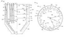
- FIG. 2is a schematic cross-sectional view of an exemplary syngas cooler that may be used with the power generation system shown in FIG. 1 ;
- FIG. 3is a cross-sectional plan-view of the syngas cooler shown in FIG. 2 .
- the present inventiongenerally provides exemplary syngas coolers to facilitate cooling syngas in an integrated gasification combined-cycle (IGCC) power generation system.
- IGCCintegrated gasification combined-cycle
- the embodiments described hereinare not limiting, but rather are exemplary only. It should be understood that the present invention may apply to any gasification system that includes a radiant cooler.
- FIG. 1is a schematic diagram of an exemplary IGCC power generation system 50 .
- IGCC system 50generally includes a main air compressor 52 , an air separation unit 54 coupled in flow communication to compressor 52 , a gasifier 56 coupled in flow communication to air separation unit 54 , a syngas cooler 57 coupled in flow communication to gasifier 56 , a gas turbine engine 10 coupled in flow communication to syngas cooler 57 , and a steam turbine 58 .
- compressor 52compresses ambient air that is channeled to air separation unit 54 .
- compressed air from a gas turbine engine compressor 12is supplied to air separation unit 54 .
- Air separation unit 54uses the compressed air to generate oxygen for use by gasifier 56 . More specifically, air separation unit 54 separates the compressed air into separate flows of oxygen (O 2 ) and a gas by-product, sometimes referred to as a “process gas.” The O 2 flow is channeled to gasifier 56 for use in generating partially combusted gases, referred to herein as “syngas,” for use by gas turbine engine 10 as fuel, as described below in more detail.
- the process gas generated by air separation unit 54includes nitrogen, referred to herein as “nitrogen process gas” (NPG).
- NPGnitrogen process gas
- the NPGmay also include other gases such as, but not limited to, oxygen and/or argon.
- the NPGincludes between about 95% to about 100% nitrogen.
- at least some of the NPG flowis vented to the atmosphere from air separation unit 54 .
- some of the NPG flowis injected into a combustion zone (not shown) within gas turbine engine combustor 14 to facilitate controlling emissions of engine 10 , and more specifically to facilitate reducing the combustion temperature and a nitrous oxide emissions of engine 10 .
- IGCC system 50also includes a compressor 60 for compressing the NPG flow before injecting the NPG into combustor 14 .
- gasifier 56converts a mixture of fuel, O 2 supplied by air separation unit 54 , steam, and/or limestone into an output of syngas 112 for use by gas turbine engine 10 as fuel.
- gasifier 56may use any fuel
- gasifier 56uses coal, petroleum coke, residual oil, oil emulsions, tar sands, and/or other similar fuels.
- syngas 112 generated by gasifier 56includes carbon dioxide (CO 2 ).
- syngas 112 generated by gasifier 56is channeled to syngas cooler 57 , which facilitates cooling syngas 112 , as described in more detail below. Cooled syngas 112 is cleaned using a clean-up device 62 before syngas 112 is channeled to gas turbine engine combustor 14 for combustion thereof.
- CO 2may be separated from syngas 112 during cleaning and may be vented to the atmosphere, captured, and/or partially returned to gasifier 56 .
- Gas turbine engine 10drives a generator 64 that supplies electrical power to a power grid (not shown). Exhaust gases from gas turbine engine 10 are channeled to a heat recovery steam generator 66 that generates steam for driving steam turbine 58 . Power generated by steam turbine 58 drives an electrical generator 68 that provides electrical power to the power grid.
- steam from heat recovery steam generator 66is also supplied to gasifier 56 as a moderator for generating syngas.
- system 50includes a pump 70 that supplies feed water 72 from steam generator 66 to syngas cooler 57 to facilitate cooling syngas 112 channeled therein from gasifier 56 .
- Feed water 72is channeled through syngas cooler 57 , wherein feed water 72 is converted to a steam 74 , as described in more detail below.
- Steam 74is then returned to steam generator 66 for use within gasifier 56 , syngas cooler 57 , and/or steam turbine 58 , and/or other processes in system 50 .
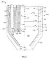
- FIG. 2is a schematic cross-sectional side-view of an exemplary syngas cooler 57 that may be used with a gasification system, such as IGCC system 50 (shown in FIG. 1 ).
- FIG. 3is a cross-sectional plan-view of syngas cooler 57 .
- syngas cooler 57is a radiant syngas cooler.
- syngas cooler 57may be any syngas cooler that includes at least one cooling tube that functions, as described in more detail below.
- syngas cooler 57includes a pressure vessel shell 100 that includes an upper shell (not shown), a lower shell 108 , and a vessel body 110 extending therebetween.
- vessel shell 100is substantially cylindrical and defines an inner chamber 106 within syngas cooler 57 .
- vessel shell 100is fabricated from a pressure quality material, such as, but not limited to, a chromium molybdenum steel. The material used in fabricating shell 100 enables shell 100 to withstand the operating pressure of syngas 112 contained within syngas cooler 57 .
- syngas cooler 57has a vessel radius R V that extends from a center axis 114 to an inner surface 116 of vessel shell 100 .
- vessel shell 100has a thickness 115 measured between an outer surface 117 and inner surface 116 . Thickness 115 , in the exemplary embodiment, is proportional to vessel radius R V of shell 100 . Specifically, as vessel radius R V is increased, thickness 115 is increased. Accordingly, such increases facilitate increasing the cost of syngas cooler 57 .
- gasifier 56(shown in FIG. 1 ) is coupled in flow communication with syngas cooler 57 such that syngas 112 discharged from gasifier 56 is channeled through an inlet (not shown) into syngas cooler 57 , and more specifically, into inner chamber 106 , as described in more detail below.
- Syngas cooler 57in the exemplary embodiment, also includes an annular membrane wall, or tube cage 120 , that is coupled within chamber 106 and that extends generally axially within syngas cooler 57 .
- Tube cage 120is aligned substantially co-axially with center axis 114 and is formed with a plurality of water tubes, or cooling tubes 124 , that each extend axially through a portion of syngas cooler 57 .
- Tube cage 120in the exemplary embodiment, includes a radially outer surface 122 and a radially inner surface 119 .
- the inner surface 119defines a heat exchange surface area (not shown) that facilitates cooling syngas 112 , as is described in more detail below.
- a gap 118is defined between vessel shell inner surface 116 and the outer surface 122 of tube cage 120 .
- Each tube cage cooling tube 124has an outer surface 122 and an opposite inner surface (not shown) that defines an inner passage (not shown) extending axially therethrough. More specifically, the inner passage of each tube cage cooling tube 124 enables cooling fluid to be channeled therethrough.
- the cooling fluid channeled within each tube cage cooling tube 124is feed water 72 .
- the cooling fluid channeled within each tube cage cooling tube 124may be any cooling fluid that is suitable for use in a radiant cooler.
- at least one pair of adjacent circumferentially-spaced apart cooling tubes 124are coupled together using a web portion (not shown).
- tube cage cooling tubes 124are fabricated from a material that facilitates heat transfer.
- each cooling tube 124is coupled in flow communication to an inlet manifold 128 .
- an upstream end (not shown) of each tube cage cooling tube 124is coupled in flow communication to a tube cage riser (not shown).
- gap 118is pressurized to facilitate preventing syngas 112 from entering space 118 .
- gap 118is pressurized with nitrogen using a pressurization system (not shown).
- the pressurization systemmaintains the pressure within gap 118 to be approximately equal to the operating pressure contained within chamber 106 .
- the pressurization systemmaintains the pressure within gap 118 at a pressure that is higher than the pressure within chamber 106 .
- the pressure within gap 118prevents syngas 112 , discharged from tube cage 120 , from entering space 118 .
- the tube cagemay not withstand a pressure differential between the annular space and the tube cage chamber of more than about 15 pounds per square inch (“psi”) to about 25 psi.
- psipounds per square inch
- tube cage 120may buckle or rupture.
- controlling the pressure within gap 118also facilitates preventing buckling or rupturing of tube cage 120 .
- Tube cage 120in the exemplary embodiment, is formed with a plurality of circumferentially-spaced chevron-shaped sections, or chevrons 170 .
- tube cage 120includes fourteen chevrons 170 .
- tube cage 120has a substantially star-shaped cross-section.
- tube cage 120may be formed with any number of chevrons 170 .
- each chevron 170includes a first side wall 172 and an opposite second side wall 174 .
- Each of the first and second side walls 172 and 174includes at least one tube cage cooling tube 124 , and the first and second side walls 172 and 174 are coupled together at a radially outer point, or chevron tip 176 .
- each chevron tip 176is circumferentially-positioned between a pair of adjacent chevron valleys 178 .
- each chevron valley 178defines a flute 180 that extends generally axially along tube cage 120 .
- Each chevron tip 176in the exemplary embodiment, is formed with a first radius R T1 and each chevron valley 178 is formed with a second radius R T2 .
- First radius R T1 and second radius R T2each extend from center axis 114 to each respective chevron tip 176 and chevron valley 178 .
- first radius R T1is longer than second radius R T2 , however, first and second radii R T1 and R T2 are each shorter than vessel radius R V . The difference in the lengths of radii R T1 and R V ensures that gap 118 is defined between inner surface 116 of vessel shell 100 and radially outer surface 122 .
- each chevron tip 176 and chevron valley 178includes at least one cooling tube 124 .
- either chevron tip 176 and/or chevron valley 178may include a plurality of cooling tubes 124 .
- chevron tip 176 and/or chevron valley 178is sized to extend generally circumferentially between first side wall 172 and second side wall 174 .
- first and second side walls 172 and 174extend substantially linearly from chevron tip 176 to chevron valley 178 .
- first side wall 172 and/or second side wall 174extends arcuately from chevron tip 176 to chevron valley 178 .
- at least one of first side wall 172 and/or second side wall 174extends in a generally sinusoidal patter.
- a length 182 of each first side wall 172is approximately equal to a length 184 of each second side wall 174 , such that chevron 170 is substantially symmetrical, about a centerline (not shown) bisecting each chevron 170 .
- first side wall length 182is different than second side wall length 184 such that chevron 170 is asymmetrical.
- Syngas cooler 57includes at least one heat transfer panel, or platen 130 , that extends generally radially from tube cage 120 towards center axis 114 .
- each platen 130may extend away from tube cage 120 at a generally oblique angle.
- at least one platen 130extends generally radially from chevron tip 176 towards center axis 114 .
- at least one platen 130extends generally radially from any point defined on tube cage 120 towards center axis 114 , wherein at least one platen 130 has a radial length that is different than a radial length of at least one other platen 130 .
- each platen 130includes a plurality of cooling tubes 132 that extend generally axially through syngas cooler 57 .
- Each platen cooling tube 132includes an outer surface 134 and an inner surface (not shown) that defines an inner passage (not shown) that extends axially through platen cooling tube 132 .
- each platen cooling tube 132in the exemplary embodiment, includes a downstream end 142 that is coupled in flow communication with a platen inlet manifold 144 .
- an upstream end (not shown) of each platen cooling tube 132is coupled in flow communication to a platen riser (not shown).
- syngas cooler 57also includes a plurality of tube cage downcomers 150 and a plurality of platen downcomers 152 that each extend generally axially within space 118 .
- downcomers 150 and 152each include an inner surface (not shown) that defines an inner passage (not shown) that extends generally axially through each downcomer 150 and 152 .
- each tube cage downcomer 150is coupled in flow communication with tube cage inlet manifold 128
- each platen downcomer 152is coupled in flow communication with platen inlet manifold 144 .
- Tube cage 120in the exemplary embodiment, as described above, has a substantially star-shaped cross-section that facilitates reducing the vessel radius R V of vessel shell 100 , with respect to known syngas coolers.
- each chevron tip 176is formed with first radius R T1 that is approximately equal to a radius of known syngas tube cages.
- each chevron valley 178is formed with second radius R T2 that is smaller than the radius of known tube cages, wherein each chevron valley 178 defines a respective flute 180 .
- Flutes 180facilitate positioning downcomers 150 and 152 closer to center axis 114 , as compared to the positions of downcomers within known syngas coolers.
- at least one downcomer 150 and/or 152is positioned within flute 180 .
- the radius R V of shell 100is reduced in comparison to known vessel shell radii.
- reducing the radius R V of shell 100facilitates a reduction in the size, thickness 115 , and manufacturing costs of syngas cooler 57 .
- chevrons 170facilitate reducing the radius R V of shell 100 by positioning at least one of downcomers 150 and/or 152 within flute 180 without causing a reduction in the heat exchange surface area of tube cage 120 .
- increasing the lengths 182 and 184 of respective first and second side walls 172 and 174facilitates reducing the radius R V of shell 100 without reducing the heat exchange surface area of tube cage 120 .
- At least one of downcomers 150 and/or 152is positioned within at least one flute 180 , adjacent to center axis 114 , thus facilitating a reduction in the radius R V of shell 100 without reducing the heat exchange surface area of tube cage 120 .
- the overall size and fabrication costs of syngas cooler 57are facilitated to be reduced without reducing the heat exchange surface area of tube cage 120 .
- chevrons 170also facilitate increasing the radial buckling strength of tube cage 120 .
- chevrons 170facilitate preventing buckling and/or rupture.
- each first and second side wall 172 and 174extend generally radially from chevron tip 176 to chevron valley 178 , such that the moment of inertia, in a radial bending direction of tube cage 120 is increased.
- tube cage 120is more resistant to buckling and/or rupturing than known syngas coolers that do not include a plurality of chevrons 170 oriented in a substantially star-shaped cross-sectional profile.
- syngas 112is discharged from gasifier 56 into chamber 106 through the syngas cooler inlet, and more specifically, into tube cage 120 .
- each platen 130extends generally radially outward from each chevron tip 176 towards center axis 114 .
- Syngas 112 discharged from gasifier 56increases the operating pressure within chamber 106 .
- the pressurization systempressurizes gap 118 such that the operating pressure within gap 118 is approximately equal to, or greater than, the pressure within chamber 106 .
- gap 118 and the pressurization systemfacilitate preventing buckling or rupture of tube cage 120 .
- syngas 112is channeled over the heat exchange surface area defined by inner surface 119 and at least one platen 130 .
- the flow of syngas 112 over the heat exchange surface area and at least one platen 130facilitates transferring heat from the flow of syngas 112 to the flow of feed water 72 channeled though cooling tubes 124 and 132 .
- Chevrons 170facilitate increasing the heat exchange surface area of tube cage 120 , and enable at least one of downcomers 150 and/or 152 to be positioned closer to center axis 114 as compared to known syngas coolers.
- At least one of downcomers 150 and/or 152is positioned within at least one flute 180 in a relative location that is closer to center axis 114 than downcomers that are positioned in known syngas coolers.
- chevrons 170facilitate reducing the vessel radius R V , and more specifically reducing the cost of syngas cooler 57 , without reducing the heat exchange surface area.
- a plurality of chevrons 170form tube cage 120 that has a generally star-shaped cross-sectional profile that facilitates reducing vessel radius R V without reducing the heat exchange surface area of tube cage 120 .
- each pair of adjacent circumferentially-spaced apart chevrons 170defines a flute 180 therebetween.
- Each flute 180facilitates positioning at least one of downcomers 150 and 152 therein such that at least one of downcomers 150 and/or 152 is positioned closer to center axis 114 than is possible with known syngas coolers.
- increasing the lengths 182 and 184 of first and second side walls 172 and 174facilitates increasing the heat exchange surface area within tube cage 120 .
- the vessel radius R Vis facilitated to be reduced, without a reduction in the amount of the heat exchange surface area of tube cage 120 .
- reducing the vessel radius R Vfacilitates reducing the thickness 115 of shell 100 which further facilitates reducing the fabrication costs of syngas cooler 57 .
- the above-described methods and apparatusfacilitate reducing the fabrication costs and size of a syngas cooler without reducing the amount of heat exchange surface area defined by a tube cage coupled within the syngas cooler.
- the tube cageincludes a plurality of circumferentially-spaced apart chevron-shaped sections, such that the tube cage has a substantially star-shaped cross-sectional profile.
- a fluteis defined between a pair of circumferentially-spaced apart chevrons, wherein the flute extends generally axially along the tube cage.
- a plurality of downcomersextends generally axially within a gap defined between the vessel and the tube cage.
- At least one downcomeris positioned within the flute such that the at least one downcomer is positioned closer to a center axis of the syngas cooler as compared to the positions of downcomers within known syngas cooler.
- the chevronsfacilitate increasing a buckling strength of the tube cage by increasing a moment of inertia in a generally radial bending direction.
- the chevronsalso facilitate increasing the heat exchange surface area of the tube cage.
- the chevronsfacilitate reducing the vessel radius without reducing the heat exchange surface area of the tube cage, and increasing the buckling strength of the tube cage.
- the chevronsfacilitate reducing the size and fabrication costs of the syngas cooler without reducing the heat exchange surface area of the tube cage.
- tube cagesincluding at least one chevron are described in detail above.
- the tube cageis not limited to use with the syngas cooler described herein, but rather, the tube cage can be utilized independently and separately from other syngas cooler components described herein.
- the inventionis not limited to the embodiments of the tube cages described above in detail. Rather, other variations of the tube cages may be utilized within the spirit and scope of the claims.
Landscapes
- Engineering & Computer Science (AREA)
- Physics & Mathematics (AREA)
- Mechanical Engineering (AREA)
- General Engineering & Computer Science (AREA)
- Thermal Sciences (AREA)
- Chemical & Material Sciences (AREA)
- Combustion & Propulsion (AREA)
- Geometry (AREA)
- Heat-Exchange Devices With Radiators And Conduit Assemblies (AREA)
Abstract
Description
Claims (17)
Priority Applications (6)
| Application Number | Priority Date | Filing Date | Title |
|---|---|---|---|
| US11/862,021US8376034B2 (en) | 2007-09-26 | 2007-09-26 | Radiant coolers and methods for assembling same |
| PCT/US2008/070056WO2009042274A1 (en) | 2007-09-26 | 2008-07-15 | Radiant coolers and methods for assembling same |
| CA2700774ACA2700774C (en) | 2007-09-26 | 2008-07-15 | Radiant coolers and methods for assembling same |
| AU2008305495AAU2008305495B2 (en) | 2007-09-26 | 2008-07-15 | Radiant coolers and methods for assembling same |
| CN200880118706.0ACN101874190B (en) | 2007-09-26 | 2008-07-15 | Radiant coolers and methods for assembling same |
| EP08832892AEP2203703A1 (en) | 2007-09-26 | 2008-07-15 | Radiant coolers and methods for assembling same |
Applications Claiming Priority (1)
| Application Number | Priority Date | Filing Date | Title |
|---|---|---|---|
| US11/862,021US8376034B2 (en) | 2007-09-26 | 2007-09-26 | Radiant coolers and methods for assembling same |
Publications (2)
| Publication Number | Publication Date |
|---|---|
| US20090078397A1 US20090078397A1 (en) | 2009-03-26 |
| US8376034B2true US8376034B2 (en) | 2013-02-19 |
Family
ID=39768641
Family Applications (1)
| Application Number | Title | Priority Date | Filing Date |
|---|---|---|---|
| US11/862,021Active2030-07-22US8376034B2 (en) | 2007-09-26 | 2007-09-26 | Radiant coolers and methods for assembling same |
Country Status (6)
| Country | Link |
|---|---|
| US (1) | US8376034B2 (en) |
| EP (1) | EP2203703A1 (en) |
| CN (1) | CN101874190B (en) |
| AU (1) | AU2008305495B2 (en) |
| CA (1) | CA2700774C (en) |
| WO (1) | WO2009042274A1 (en) |
Families Citing this family (5)
| Publication number | Priority date | Publication date | Assignee | Title |
|---|---|---|---|---|
| US9109173B2 (en) | 2009-06-30 | 2015-08-18 | General Electric Company | Gasification quench chamber dip tube |
| US8986403B2 (en) | 2009-06-30 | 2015-03-24 | General Electric Company | Gasification system flow damping |
| US10227924B2 (en)* | 2013-08-16 | 2019-03-12 | Rolls-Royce North American Technologies Inc. | Particle separator |
| US9321975B2 (en)* | 2013-12-06 | 2016-04-26 | General Electric Company | System and method for cooling syngas within a gasifier system |
| US10234210B2 (en)* | 2016-08-24 | 2019-03-19 | General Electric Company | RSC external downcomer tube arrangement |
Citations (40)
| Publication number | Priority date | Publication date | Assignee | Title |
|---|---|---|---|---|
| US1774136A (en)* | 1927-02-26 | 1930-08-26 | Forssblad Nils | Combustion-chamber wall for steam boilers |
| US2570073A (en)* | 1945-11-03 | 1951-10-02 | George P Reintjes | Furnace wall |
| US2610832A (en)* | 1947-08-02 | 1952-09-16 | Gen Motors Corp | Condenser |
| US2804284A (en)* | 1953-04-03 | 1957-08-27 | Griscom Russell Co | Heat exchanger |
| US3830623A (en) | 1972-01-17 | 1974-08-20 | Smidth & Co As F L | Cooler tube for rotary kiln |
| US3850453A (en) | 1972-10-04 | 1974-11-26 | Questor Corp | Method and apparatus for connecting insulating conduits |
| US4045285A (en) | 1974-11-23 | 1977-08-30 | Hochtemperatur-Reactorbau Gmbh. | Plant for the production of hydrogen through utilization of heat energy obtained from a gas-cooled nuclear reactor |
| US4236576A (en) | 1978-09-14 | 1980-12-02 | Borsig Gmbh | Heat exchangers with tube bundles |
| US4265301A (en)* | 1976-04-06 | 1981-05-05 | Anderson James H | Heat exchanger support construction |
| US4299273A (en)* | 1977-09-14 | 1981-11-10 | Sulzer Brothers Ltd. | Heat exchanger, especially recuperator for high temperature reactors |
| EP0048326A2 (en) | 1980-09-19 | 1982-03-31 | GebràDer Sulzer Aktiengesellschaft | Hot-gas cooler for a coal gasification plant |
| US4332293A (en) | 1980-04-30 | 1982-06-01 | Nippondenso Co., Ltd. | Corrugated fin type heat exchanger |
| US4372253A (en)* | 1979-10-04 | 1983-02-08 | Ruhrchemie Aktiengesellschaft | Radiation boiler |
| US4451960A (en) | 1979-03-15 | 1984-06-05 | Molitor Industries, Inc. | Method of producing multiple coil, multiple tube heat exchanger |
| US4456058A (en)* | 1982-11-30 | 1984-06-26 | Brown Fintube Company | Heat exchanger tube support |
| US4479355A (en)* | 1983-02-25 | 1984-10-30 | Exxon Research & Engineering Co. | Power plant integrating coal-fired steam boiler with air turbine |
| US4509463A (en)* | 1982-12-24 | 1985-04-09 | M.A.N. Maschinenfabrik Ausburg-Nurnberg Aktiengesellschaft | Upright apparatus for cooling high pressure gases containing a high dust content |
| US4513694A (en)* | 1982-07-12 | 1985-04-30 | Willem Wiemer | Vertical radiation tank |
| US4538676A (en)* | 1982-02-24 | 1985-09-03 | L & C. Steinmuller Gmbh | Gas liquid parallel flow direct current heat exchanger |
| EP0223534A2 (en) | 1985-11-22 | 1987-05-27 | Pentagon Radiator (Stafford) Limited | Heat Exchangers |
| US4841917A (en) | 1987-07-31 | 1989-06-27 | L. & C. Steinmuller Gmbh | Radiation cooling unit for cooling dust-laden gases |
| US5099916A (en) | 1990-03-12 | 1992-03-31 | Man Gutehoffnungshutte Ag | Cooler for particle-laden gases |
| US5107683A (en) | 1990-04-09 | 1992-04-28 | Trw Inc. | Multistage pulse tube cooler |
| US5233943A (en) | 1990-11-19 | 1993-08-10 | Texaco Inc. | Synthetic gas radiant cooler with internal quenching and purging facilities |
| US5251692A (en) | 1991-06-20 | 1993-10-12 | Thermal-Werke Warme-, Kalte-, Klimatechnik Gmbh | Flat tube heat exchanger, method of making the same and flat tubes for the heat exchanger |
| US5251693A (en)* | 1992-10-19 | 1993-10-12 | Zifferer Lothar R | Tube-in-shell heat exchanger with linearly corrugated tubing |
| US5271809A (en) | 1991-08-28 | 1993-12-21 | Selas-Kirchner Gmbh | Pyrolytic furnace for the thermal cracking of hydrocarbons |
| US5277247A (en)* | 1992-06-29 | 1994-01-11 | Cameron Gordon M | Heat exchanger having improved tube layout |
| EP0536134B1 (en) | 1990-01-05 | 1994-07-13 | BURMEISTER & WAIN ENERGI A/S | Gas cooler for heat transfer by radiation |
| US5449037A (en)* | 1993-12-08 | 1995-09-12 | Brown Fintube Corporation | Heat exchanger tube spacer, separator, and support |
| US5697435A (en) | 1993-12-22 | 1997-12-16 | Teledyne Industries, Inc. | Heat exchanger systems |
| US5806585A (en) | 1995-02-27 | 1998-09-15 | Mitsubishi Denki Kabushiki Kaisha | Heat exchanger, refrigeration system, air conditioner, and method and apparatus for fabricating heat exchanger |
| US6269782B1 (en)* | 1999-08-02 | 2001-08-07 | Miura Co., Ltd. | Water-tube boiler |
| US20030005634A1 (en) | 2001-07-09 | 2003-01-09 | Albert Calderon | Method for producing clean energy from coal |
| US20040108098A1 (en)* | 2002-11-13 | 2004-06-10 | Sanders Stan A. | Cellular reservoir flexible pressure vesssel, apparatus and method for making same |
| WO2005005040A1 (en) | 2003-07-14 | 2005-01-20 | Dsm Ip Assets B.V. | Heat exchanger and reactor comprising said type of heat exchanger |
| US20070028860A1 (en)* | 2005-08-08 | 2007-02-08 | Utilization Technology Development, Nfp | Recuperative reforming reactor |
| US20070119577A1 (en)* | 2005-11-03 | 2007-05-31 | Kraft Dave L | Radiant syngas cooler |
| US20090025917A1 (en)* | 2007-07-26 | 2009-01-29 | Robert Henri Gauthier | Method and apparatus for heat recovery within a syngas cooler |
| US7749290B2 (en)* | 2007-01-19 | 2010-07-06 | General Electric Company | Methods and apparatus to facilitate cooling syngas in a gasifier |
- 2007
- 2007-09-26USUS11/862,021patent/US8376034B2/enactiveActive
- 2008
- 2008-07-15CNCN200880118706.0Apatent/CN101874190B/enactiveActive
- 2008-07-15AUAU2008305495Apatent/AU2008305495B2/ennot_activeCeased
- 2008-07-15EPEP08832892Apatent/EP2203703A1/ennot_activeWithdrawn
- 2008-07-15WOPCT/US2008/070056patent/WO2009042274A1/enactiveApplication Filing
- 2008-07-15CACA2700774Apatent/CA2700774C/ennot_activeExpired - Fee Related
Patent Citations (41)
| Publication number | Priority date | Publication date | Assignee | Title |
|---|---|---|---|---|
| US1774136A (en)* | 1927-02-26 | 1930-08-26 | Forssblad Nils | Combustion-chamber wall for steam boilers |
| US2570073A (en)* | 1945-11-03 | 1951-10-02 | George P Reintjes | Furnace wall |
| US2610832A (en)* | 1947-08-02 | 1952-09-16 | Gen Motors Corp | Condenser |
| US2804284A (en)* | 1953-04-03 | 1957-08-27 | Griscom Russell Co | Heat exchanger |
| US3830623A (en) | 1972-01-17 | 1974-08-20 | Smidth & Co As F L | Cooler tube for rotary kiln |
| US3850453A (en) | 1972-10-04 | 1974-11-26 | Questor Corp | Method and apparatus for connecting insulating conduits |
| US4045285A (en) | 1974-11-23 | 1977-08-30 | Hochtemperatur-Reactorbau Gmbh. | Plant for the production of hydrogen through utilization of heat energy obtained from a gas-cooled nuclear reactor |
| US4265301A (en)* | 1976-04-06 | 1981-05-05 | Anderson James H | Heat exchanger support construction |
| US4299273A (en)* | 1977-09-14 | 1981-11-10 | Sulzer Brothers Ltd. | Heat exchanger, especially recuperator for high temperature reactors |
| US4236576A (en) | 1978-09-14 | 1980-12-02 | Borsig Gmbh | Heat exchangers with tube bundles |
| US4451960A (en) | 1979-03-15 | 1984-06-05 | Molitor Industries, Inc. | Method of producing multiple coil, multiple tube heat exchanger |
| US4372253A (en)* | 1979-10-04 | 1983-02-08 | Ruhrchemie Aktiengesellschaft | Radiation boiler |
| US4332293A (en) | 1980-04-30 | 1982-06-01 | Nippondenso Co., Ltd. | Corrugated fin type heat exchanger |
| EP0048326A2 (en) | 1980-09-19 | 1982-03-31 | GebràDer Sulzer Aktiengesellschaft | Hot-gas cooler for a coal gasification plant |
| US4395268A (en)* | 1980-09-19 | 1983-07-26 | Jaroslav Zabelka | Hot gas cooler for a coal gasification plant |
| US4538676A (en)* | 1982-02-24 | 1985-09-03 | L & C. Steinmuller Gmbh | Gas liquid parallel flow direct current heat exchanger |
| US4513694A (en)* | 1982-07-12 | 1985-04-30 | Willem Wiemer | Vertical radiation tank |
| US4456058A (en)* | 1982-11-30 | 1984-06-26 | Brown Fintube Company | Heat exchanger tube support |
| US4509463A (en)* | 1982-12-24 | 1985-04-09 | M.A.N. Maschinenfabrik Ausburg-Nurnberg Aktiengesellschaft | Upright apparatus for cooling high pressure gases containing a high dust content |
| US4479355A (en)* | 1983-02-25 | 1984-10-30 | Exxon Research & Engineering Co. | Power plant integrating coal-fired steam boiler with air turbine |
| EP0223534A2 (en) | 1985-11-22 | 1987-05-27 | Pentagon Radiator (Stafford) Limited | Heat Exchangers |
| US4841917A (en) | 1987-07-31 | 1989-06-27 | L. & C. Steinmuller Gmbh | Radiation cooling unit for cooling dust-laden gases |
| EP0536134B1 (en) | 1990-01-05 | 1994-07-13 | BURMEISTER & WAIN ENERGI A/S | Gas cooler for heat transfer by radiation |
| US5099916A (en) | 1990-03-12 | 1992-03-31 | Man Gutehoffnungshutte Ag | Cooler for particle-laden gases |
| US5107683A (en) | 1990-04-09 | 1992-04-28 | Trw Inc. | Multistage pulse tube cooler |
| US5233943A (en) | 1990-11-19 | 1993-08-10 | Texaco Inc. | Synthetic gas radiant cooler with internal quenching and purging facilities |
| US5251692A (en) | 1991-06-20 | 1993-10-12 | Thermal-Werke Warme-, Kalte-, Klimatechnik Gmbh | Flat tube heat exchanger, method of making the same and flat tubes for the heat exchanger |
| US5271809A (en) | 1991-08-28 | 1993-12-21 | Selas-Kirchner Gmbh | Pyrolytic furnace for the thermal cracking of hydrocarbons |
| US5277247A (en)* | 1992-06-29 | 1994-01-11 | Cameron Gordon M | Heat exchanger having improved tube layout |
| US5251693A (en)* | 1992-10-19 | 1993-10-12 | Zifferer Lothar R | Tube-in-shell heat exchanger with linearly corrugated tubing |
| US5449037A (en)* | 1993-12-08 | 1995-09-12 | Brown Fintube Corporation | Heat exchanger tube spacer, separator, and support |
| US5697435A (en) | 1993-12-22 | 1997-12-16 | Teledyne Industries, Inc. | Heat exchanger systems |
| US5806585A (en) | 1995-02-27 | 1998-09-15 | Mitsubishi Denki Kabushiki Kaisha | Heat exchanger, refrigeration system, air conditioner, and method and apparatus for fabricating heat exchanger |
| US6269782B1 (en)* | 1999-08-02 | 2001-08-07 | Miura Co., Ltd. | Water-tube boiler |
| US20030005634A1 (en) | 2001-07-09 | 2003-01-09 | Albert Calderon | Method for producing clean energy from coal |
| US20040108098A1 (en)* | 2002-11-13 | 2004-06-10 | Sanders Stan A. | Cellular reservoir flexible pressure vesssel, apparatus and method for making same |
| WO2005005040A1 (en) | 2003-07-14 | 2005-01-20 | Dsm Ip Assets B.V. | Heat exchanger and reactor comprising said type of heat exchanger |
| US20070028860A1 (en)* | 2005-08-08 | 2007-02-08 | Utilization Technology Development, Nfp | Recuperative reforming reactor |
| US20070119577A1 (en)* | 2005-11-03 | 2007-05-31 | Kraft Dave L | Radiant syngas cooler |
| US7749290B2 (en)* | 2007-01-19 | 2010-07-06 | General Electric Company | Methods and apparatus to facilitate cooling syngas in a gasifier |
| US20090025917A1 (en)* | 2007-07-26 | 2009-01-29 | Robert Henri Gauthier | Method and apparatus for heat recovery within a syngas cooler |
Non-Patent Citations (1)
| Title |
|---|
| International Search Report, PCT/US2008/070056, dated Oct. 15, 2008, 4 pages. |
Also Published As
| Publication number | Publication date |
|---|---|
| AU2008305495A1 (en) | 2009-04-02 |
| US20090078397A1 (en) | 2009-03-26 |
| EP2203703A1 (en) | 2010-07-07 |
| CA2700774C (en) | 2015-11-03 |
| CA2700774A1 (en) | 2009-04-02 |
| CN101874190A (en) | 2010-10-27 |
| CN101874190B (en) | 2012-10-10 |
| WO2009042274A1 (en) | 2009-04-02 |
| AU2008305495B2 (en) | 2013-03-07 |
Similar Documents
| Publication | Publication Date | Title |
|---|---|---|
| CA2694964C (en) | Radiant coolers and methods for assembling same | |
| US7730616B2 (en) | Methods to facilitate cooling syngas in a gasifier | |
| CN101881453B (en) | Airblown syngas fuel nozzle with diluent openings | |
| EP2183538B1 (en) | Heat recovery system and method of assembling a syngas cooler | |
| CN102538013B (en) | There is the fuel injector of tip cooling | |
| US8376034B2 (en) | Radiant coolers and methods for assembling same | |
| US8191617B2 (en) | Syngas cooler and cooling tube for use in a syngas cooler | |
| US9464610B2 (en) | Fuel injector having differential tip cooling system and method | |
| US20090130001A1 (en) | Methods for fabricating syngas cooler platens and syngas cooler platens | |
| US8151716B2 (en) | Feed injector cooling apparatus and method of assembly | |
| US8287815B2 (en) | Methods and systems for controlling temperature in a vessel | |
| US20110243804A1 (en) | Method and system for superheating steam | |
| US20110072721A1 (en) | Method of assembly and apparatus for cooling syngas |
Legal Events
| Date | Code | Title | Description |
|---|---|---|---|
| AS | Assignment | Owner name:GENERAL ELECTRIC COMPANY, NEW YORK Free format text:ASSIGNMENT OF ASSIGNORS INTEREST;ASSIGNORS:STOREY, JAMES MICHAEL;AVAGLIANO, AARON JOHN;GERBODE, ASHLEY NICOLE;AND OTHERS;REEL/FRAME:019889/0606;SIGNING DATES FROM 20070921 TO 20070924 Owner name:GENERAL ELECTRIC COMPANY, NEW YORK Free format text:ASSIGNMENT OF ASSIGNORS INTEREST;ASSIGNORS:STOREY, JAMES MICHAEL;AVAGLIANO, AARON JOHN;GERBODE, ASHLEY NICOLE;AND OTHERS;SIGNING DATES FROM 20070921 TO 20070924;REEL/FRAME:019889/0606 | |
| FEPP | Fee payment procedure | Free format text:PAYOR NUMBER ASSIGNED (ORIGINAL EVENT CODE: ASPN); ENTITY STATUS OF PATENT OWNER: LARGE ENTITY | |
| STCF | Information on status: patent grant | Free format text:PATENTED CASE | |
| FPAY | Fee payment | Year of fee payment:4 | |
| AS | Assignment | Owner name:AIR PRODUCTS AND CHEMICALS, INC., PENNSYLVANIA Free format text:ASSIGNMENT OF ASSIGNORS INTEREST;ASSIGNOR:GENERAL ELECTRIC COMPANY;REEL/FRAME:050786/0768 Effective date:20191002 | |
| MAFP | Maintenance fee payment | Free format text:PAYMENT OF MAINTENANCE FEE, 8TH YEAR, LARGE ENTITY (ORIGINAL EVENT CODE: M1552); ENTITY STATUS OF PATENT OWNER: LARGE ENTITY Year of fee payment:8 | |
| MAFP | Maintenance fee payment | Free format text:PAYMENT OF MAINTENANCE FEE, 12TH YEAR, LARGE ENTITY (ORIGINAL EVENT CODE: M1553); ENTITY STATUS OF PATENT OWNER: LARGE ENTITY Year of fee payment:12 |