Movatterモバイル変換


[0]ホーム

URL:


US8374489B2 - Method and apparatus for inducing and or reducing geometric distortions in a display via positive going pulses - Google Patents

Method and apparatus for inducing and or reducing geometric distortions in a display via positive going pulses
Download PDF

Info

Publication number
US8374489B2
US8374489B2US12/565,531US56553109AUS8374489B2US 8374489 B2US8374489 B2US 8374489B2US 56553109 AUS56553109 AUS 56553109AUS 8374489 B2US8374489 B2US 8374489B2
Authority
US
United States
Prior art keywords
pulses
pulse
positive going
lines
display
Prior art date
Legal status (The legal status is an assumption and is not a legal conclusion. Google has not performed a legal analysis and makes no representation as to the accuracy of the status listed.)
Expired - Fee Related, expires
Application number
US12/565,531
Other versions
US20110069233A1 (en
Inventor
Ronald Quan
Current Assignee (The listed assignees may be inaccurate. Google has not performed a legal analysis and makes no representation or warranty as to the accuracy of the list.)
Adeia Technologies Inc
Original Assignee
Rovi Technologies Corp
Priority date (The priority date is an assumption and is not a legal conclusion. Google has not performed a legal analysis and makes no representation as to the accuracy of the date listed.)
Filing date
Publication date
Application filed by Rovi Technologies CorpfiledCriticalRovi Technologies Corp
Priority to US12/565,531priorityCriticalpatent/US8374489B2/en
Assigned to ROVI TECHNOLOGIES CORPORATIONreassignmentROVI TECHNOLOGIES CORPORATIONASSIGNMENT OF ASSIGNORS INTEREST (SEE DOCUMENT FOR DETAILS).Assignors: QUAN, RONALD
Priority to PCT/US2010/048731prioritypatent/WO2011037782A2/en
Priority to EP10766147Aprioritypatent/EP2481212A2/en
Publication of US20110069233A1publicationCriticalpatent/US20110069233A1/en
Assigned to JPMORGAN CHASE BANK, N.A., AS COLLATERAL AGENTreassignmentJPMORGAN CHASE BANK, N.A., AS COLLATERAL AGENTSECURITY INTEREST (SEE DOCUMENT FOR DETAILS).Assignors: APTIV DIGITAL, INC., A DELAWARE CORPORATION, GEMSTAR DEVELOPMENT CORPORATION, A CALIFORNIA CORPORATION, INDEX SYSTEMS INC, A BRITISH VIRGIN ISLANDS COMPANY, ROVI CORPORATION, A DELAWARE CORPORATION, ROVI GUIDES, INC., A DELAWARE CORPORATION, ROVI SOLUTIONS CORPORATION, A DELAWARE CORPORATION, ROVI TECHNOLOGIES CORPORATION, A DELAWARE CORPORATION, STARSIGHT TELECAST, INC., A CALIFORNIA CORPORATION, UNITED VIDEO PROPERTIES, INC., A DELAWARE CORPORATION
Application grantedgrantedCritical
Publication of US8374489B2publicationCriticalpatent/US8374489B2/en
Assigned to UNITED VIDEO PROPERTIES, INC., GEMSTAR DEVELOPMENT CORPORATION, STARSIGHT TELECAST, INC., INDEX SYSTEMS INC., TV GUIDE INTERNATIONAL, INC., ALL MEDIA GUIDE, LLC, APTIV DIGITAL, INC., ROVI CORPORATION, ROVI TECHNOLOGIES CORPORATION, ROVI SOLUTIONS CORPORATION, ROVI GUIDES, INC.reassignmentUNITED VIDEO PROPERTIES, INC.PATENT RELEASEAssignors: JPMORGAN CHASE BANK, N.A., AS COLLATERAL AGENT
Assigned to MORGAN STANLEY SENIOR FUNDING, INC., AS COLLATERAL AGENTreassignmentMORGAN STANLEY SENIOR FUNDING, INC., AS COLLATERAL AGENTPATENT SECURITY AGREEMENTAssignors: APTIV DIGITAL, INC., GEMSTAR DEVELOPMENT CORPORATION, INDEX SYSTEMS INC., ROVI GUIDES, INC., ROVI SOLUTIONS CORPORATION, ROVI TECHNOLOGIES CORPORATION, SONIC SOLUTIONS LLC, STARSIGHT TELECAST, INC., UNITED VIDEO PROPERTIES, INC., VEVEO, INC.
Assigned to HPS INVESTMENT PARTNERS, LLC, AS COLLATERAL AGENTreassignmentHPS INVESTMENT PARTNERS, LLC, AS COLLATERAL AGENTSECURITY INTEREST (SEE DOCUMENT FOR DETAILS).Assignors: ROVI GUIDES, INC., ROVI SOLUTIONS CORPORATION, ROVI TECHNOLOGIES CORPORATION, Tivo Solutions, Inc., VEVEO, INC.
Assigned to MORGAN STANLEY SENIOR FUNDING, INC., AS COLLATERAL AGENTreassignmentMORGAN STANLEY SENIOR FUNDING, INC., AS COLLATERAL AGENTPATENT SECURITY AGREEMENTAssignors: ROVI GUIDES, INC., ROVI SOLUTIONS CORPORATION, ROVI TECHNOLOGIES CORPORATION, Tivo Solutions, Inc., VEVEO, INC.
Assigned to GEMSTAR DEVELOPMENT CORPORATION, APTIV DIGITAL INC., VEVEO, INC., ROVI TECHNOLOGIES CORPORATION, ROVI GUIDES, INC., INDEX SYSTEMS INC., STARSIGHT TELECAST, INC., UNITED VIDEO PROPERTIES, INC., SONIC SOLUTIONS LLC, ROVI SOLUTIONS CORPORATIONreassignmentGEMSTAR DEVELOPMENT CORPORATIONRELEASE OF SECURITY INTEREST IN PATENT RIGHTSAssignors: MORGAN STANLEY SENIOR FUNDING, INC., AS COLLATERAL AGENT
Assigned to BANK OF AMERICA, N.A.reassignmentBANK OF AMERICA, N.A.SECURITY INTEREST (SEE DOCUMENT FOR DETAILS).Assignors: DTS, INC., IBIQUITY DIGITAL CORPORATION, INVENSAS BONDING TECHNOLOGIES, INC., INVENSAS CORPORATION, PHORUS, INC., ROVI GUIDES, INC., ROVI SOLUTIONS CORPORATION, ROVI TECHNOLOGIES CORPORATION, TESSERA ADVANCED TECHNOLOGIES, INC., TESSERA, INC., TIVO SOLUTIONS INC., VEVEO, INC.
Assigned to Tivo Solutions, Inc., ROVI TECHNOLOGIES CORPORATION, ROVI GUIDES, INC., VEVEO, INC., ROVI SOLUTIONS CORPORATIONreassignmentTivo Solutions, Inc.RELEASE BY SECURED PARTY (SEE DOCUMENT FOR DETAILS).Assignors: HPS INVESTMENT PARTNERS, LLC
Assigned to VEVEO, INC., ROVI GUIDES, INC., Tivo Solutions, Inc., ROVI SOLUTIONS CORPORATION, ROVI TECHNOLOGIES CORPORATIONreassignmentVEVEO, INC.RELEASE BY SECURED PARTY (SEE DOCUMENT FOR DETAILS).Assignors: MORGAN STANLEY SENIOR FUNDING, INC.
Expired - Fee Relatedlegal-statusCriticalCurrent
Adjusted expirationlegal-statusCritical

Links

Images

Classifications

Definitions

Landscapes

Abstract

In certain flat screen TV sets, such as LCD monitors, geometric errors can be induced in a video signal by positive going pulses. That is, a shift in a display is provided when one or more positive going pulse is added to the video signal following one or more sync pulse. To illustrate, AGC pulses, generally used for content control and or copy protection in the last lines of an active video field, cause a shift (horizontal displacement) in the picture for these last lines in the active field. Alternatively, turning off or attenuating such positive going pulses in the last lines of the active field, eliminates or reduces the picture shift.

Description

BACKGROUND
The present invention relates to copy protection signals which are caused by positive going pulses, wherein the signals are playable but not recordable. Heretofore, playability in terms of geometric distortion has been related only to negative going pulses such as pseudo sync pulses. The negative going pulses cause the sync separator circuit and horizontal oscillator in TV sets such as those having a CRT (cathode ray tube) monitor, to generate a slight erroneous scan.
SUMMARY
To the contrary, in certain flat screen TV sets such as LCD monitors, it is found that geometric errors can be induced in a video signal display by positive going pulses. That is, a shift in the display is provided when one or more positive going pulse follows one or more sync pulse. For example, automatic gain control (AGC) pulses, generally used for content control and or copy protection in the last lines of an active field, cause a shift (e.g., a horizontal displacement) in the picture for these last lines of the active field.
An embodiment comprises a method of applying one or more positive going pulses in the horizontal blanking interval in one or more TV line to induce shifting in the one or more TV line on a display such as a flat screen TV, including (geometric) shifting as seen on the display in the location of the line(s) in which the one or more positive going pulses in the horizontal blanking interval is applied to, or inserted or added to.
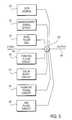
Another embodiment applies one or more positive going pulse in the horizontal blanking interval in one or more TV line, and one or more added pseudo sync/AGC pulse pair signal(s) in TV lines other than the lines containing the positive going pulses in the horizontal blanking interval. This induces (geometric) shifting in one or more TV line (of the display), which includes the one or more positive going pulse.
In yet another embodiment, programming or providing a (geometric) shift in a portion of the active field is combined with a content control signal and or copy protection signal (which causes a “black box” to pass through at least one of the copy protection signals). This embodiment provides resistance to “black boxes” (copy protection circumvention devices) or provides added enhancement to a copy protection process via the black box. It follows that the black box becomes an “unwitting” processing circuit to cause blanking in a portion of a video signal, which then enhances a copy protection effect.
In another embodiment of the invention, adding positive going pulses in a portion of the active field and adding negative going pulses in a portion of the vertical blanking interval provides a geometric shift pattern in a portion of the active video field and in a portion of the vertical blanking interval.
Various embodiments for defeating or for controlling the amount of shifting also are described further herein. One embodiment includes removing or attenuating one or more AGC pulse in a portion of an active field to provide means for reducing the amount of geometric shifting of a displayed picture on a monitor.
Thus, in an alternative embodiment, attenuating or turning off the AGC pulses in the last lines of the active field and or the pseudo sync/AGC pulse pairs in the vertical blanking interval, reduces or eliminates the picture shift.
BRIEF DESCRIPTION OF THE DRAWINGS
FIG. 1 is a waveform illustrating the response of a TV monitor to a normal video signal and to a pseudo sync pulse, as exists in the prior art.
FIG. 2A is a waveform illustrating the response of a TV monitor to a positive going pulse, as exists in the prior art.
FIG. 2B is a waveform illustrating the response of a different TV monitor to a positive going pulse, in accordance with the invention.
FIG. 3 is a block diagram illustrating an embodiment(s) of the invention.
FIG. 4 is a block diagram illustrating another embodiment of the invention.
FIG. 5 is a block diagram illustrating a further embodiment of the invention.
FIG. 6 is a block diagram illustrating yet another embodiment of the invention in an associated environment.
DETAILED DESCRIPTION
A copy protection process disclosed in U.S. Pat. No. 4,631,603 by John O. Ryan, December 1986, assigned to Macrovision Corporation, Santa Clara, Calif., incorporated by reference, is well known to have placed pseudo sync and AGC pulses in specific television (TV) lines for pre-recorded video home systems (VHS) tape and digital video disc (DVD) playback devices.FIG. 1 shows a video signal withnormal sync pulses11 in the active field, which, when displayed, shows normal scanning by aTV monitor16. Also shown inFIG. 1, in TV lines in the bottom of the active field, are additionalpseudo sync pulse12 and a positive going pulse (AGC)15, which cause a displacement orpositional shift13 in the normal scan onmonitor16. In practice, whenpositive pulse15 is attenuated or removed, negative goingpulse12 causes the displacement or geometric/positional shift as seen at13.
Copy protection processes disclosed in U.S. Pat. Nos. 4,819,098 and 5,130,810, by John O. Ryan, April 1989 and July 1992 respectively, assigned to Macrovision Corporation, Santa Clara, Calif., incorporated by reference, are well known to have placed AGC pulses following a horizontal sync pulse in specific television (TV) lines for pre-recorded video home systems (VHS) tape and digital video disc (DVD) playback devices. Another patent, U.S. Pat. No. 4,163,253 by Morio July 1978, incorporated by reference, also shows placing AGC pulses after horizontal sync pulses.FIG. 2A shows a video signal with a positive goingpulse14 following the sync pulse11 (in a horizontal blanking interval) and added to the last lines of the active field. A typical TV monitor such as aCRT display16, provides a normal scan, without deviation or shifting at the bottom of a displayed picture.
FIG. 2B shows a video signal with a positive goingpulse14 added to the last video lines of the active field wherein the video signal is coupled to a different type of TV monitor,16′ (such as an liquid crystal display (LCD), TFT display, or flat screen display). Here, in the lines that have the positive going pulses (e.g., a positive going pulse in a horizontal blanking interval), the displayed program material or video signal is geometrically shifted or displaced unexpectedly on the last lines of the active field on themonitor16′, as illustrated at17. In some flat screen displays with a horizontal and vertical delay (HV delay), that show the horizontal blanking interval and vertical blanking interval within the frame of the display, the one or more positive going pulses by themselves or in combination with pseudo sync pulses in succeeding lines causes a displacement in one or more line in the location of the positive going pulses, prior to the pseudo sync pulses.
FIG. 3 shows an example of apparatus for providing the positive going pulses that generate the positional shift or displacement on a TV monitor, such as depicted inFIG. 2B, wherein the TV monitor may be in a normal scan, an underscan, or a delayed horizontal and or delayed vertical scan mode.
Video in the form of an analog or digital video signal is coupled via aninput19 to a combiningcircuit20. In turn, combiningcircuit20 is selectively coupled to, adata source21, anenhancement signal circuit22, async pulse generator23, a positive goingpulse circuit24, a negative goingpulse circuit25, anAGC pulse circuit26 and a colorburst signal circuit27. Therefore, the combiningcircuit20 may receive a signal or signals from one or more of the circuits21-27 and functions to combine the one or more signals with the video signal oninput19 to provide a resulting output signal onoutput30. More particularly, the combiningcircuit20 may include or be coupled to, a data signal fromdata source21, a copy protection enhancement signal from theenhancement signal circuit22, horizontal and or vertical sync pulses from thesync pulse generator23, positive going pulses from thepositive pulse circuit24, negative going pulses fromnegative pulse circuit25, AGC pulses from theAGC pulse circuit26 and or a color burst signal from thecolor burst circuit27.
Generally, the AGC pulses fromcircuit26 form for example a pulse pair signal with negative going pulses fromcircuit25, to provide for example a pseudo sync/AGC pulse pair signal. It is noted that modulation of the AGC pulse in the pseudo sync/AGC pulse pair signal may be provided or generated. Modulation may include amplitude, frequency, position, pulse width, and or phase modulation of one or more positive going pulses.
Positive going pulses from thecircuit24 generally are “paired” with horizontal and or equalizing pulses from, for example, thesync pulse generator23.
When the positive going pulses are activated, certain types of TV monitors (e.g., LCD, TFT or flat screen monitors) will exhibit a positional shift, or displacement, as described for example inFIG. 2B. Should a pseudo sync pulse be inserted or added, a further positional shift in a display is provided, usually in a different area from the location of the positive going pulses. Should AGC pulses be added, then an output signal fromoutput30 will comprise a copy protection signal, which causes additional shifting of the picture on a monitor.
An embodiment where modulation of the pseudo sync/AGC pulse pair signal is applied (e.g., amplitude modulation of the AGC pulses), along with the positive going pulses, provides a dynamic copy protection effect on a recorder, which provides an additional shift in the display during at least one line of the location of the positive going pulses.
Theenhancement signal circuit22 generally adds a level shifting voltage to an active picture area, and or to a portion of the front and or back porch of selected line(s) of the video signal. In an alternative embodiment, one or more negative going pulse, which is detectable by a sync separator, may be provided in sufficient TV line(s) after a post equalizing pulse of a vertical sync signal, to cause resistance to a black box, or to cause a black box to unexpectingly enhance the copy protection effect. For example, such resistance or enhancement may include, the black box in response to newly specified location of negative going or pseudo sync pulses (immediately or 1 or less than 2 or 2.5 lines) following a vertical sync signal or post equalizing pulse. The black box or circumvention device then causes blanking one or more color burst and or one or more portion of one or more active field TV line, or causes the circumvention device to sufficiently blank out portions of the video signal to impair reading of data/reference/test signals, such as closed caption signal(s).
Not shown inFIG. 3 is a color burst modification, which includes phase modulation of at least a portion of the color burst signal over one or more lines. This phase modulation may be added as a process for copy protection and or content control.
FIG. 4 shows aprogrammable generator41, which inserts or adds any of the waveforms, or signals from the circuits21-27, as seen inFIG. 2B or3, respectively. Here one or more bit pattern(s) on aninput42 activate or deactivate the added positive going, negative going, and or enhancement signal(s). The bit pattern may be stored, read, entered, generated, or received.
FIG. 5 shows a simplified block diagram51 withvideo input52 andoutput53, wherein positive going pulses provide the (geometrical) positional shift, and pseudo sync AGC pulses provide a content control and or copy protection signal.
A copy protection process disclosed in U.S. patent application Ser. No. 12/322,004 by Ronald Quan, assigned to Macrovision Corporation, Santa Clara, Calif., shows methods of generating pseudo sync pulses (and or pulse signals) to provide resistance to circumvention devices (or cause certain circumvention devices to enhance a copy protection signal) is incorporated by reference. Also U.S. Pat. No. 6,836,549 (incorporated by reference) by Ronald Quan, shows methods of position, pulse-width, and or amplitude modification or modulation of sync, pseudo sync, and or AGC pulses.FIG. 6 shows an alternate process for pseudo sync and or pulse pair signals. Either or both of these signals are located, for example, in the VBI and or its vicinity of line(s) in a manner to provide a signal such that a circumvention device causes blanking and or other artifacts in combination with a shifting effect toward the bottom of the screen, via positive going pulses in the HBI in selected lines. A description of certain black boxes (or circumvention devices) is included below. Also, a description of how playability can be improved in the VBI region and or in the one or more lines following the VBI is also included below. Improved playability in the VBI region and or line(s) after the VBI is combined with the shifting effect caused by the positive going pulses in selected HBI of TV lines via location and formatting of pseudo sync signals. For example, moving/shifting pseudo sync signals closer to the vertical sync signal (or closer to a post pseudo sync signal/pulse), or interweaving the pseudo sync AGC signals in an alternating manner of Format A followed by Format B, to synthesize two or more consecutive TV lines with Format A or Format B.
For example, Format A may include N number of pseudo sync pulses per lines, and Format B may include M number of pseudo sync pulses per line. Generally, M is not equal to N. Also, Format A may have different pulse width (and or position) of pseudo sync pulses, than does Format B. For improved playablility, a series of TV lines with pseudo sync pulses can have an alternating pattern of Format A and Format B, and two (or more) TV lines with Format A=Format B (or where M=N) in a consecutive manner.
In some circumvention devices it was found experimentally that the black box devices can be disabled by observing the behavior of the microprocessors or certain traditional timing circuits in the black boxes, while still providing an effective anti-copy protection signal at the output of the device. To reiterate, an anti-copy protection signal or video copy protected signal is playable on a TV display, while prohibiting recording. That is, recording is prohibited by causing an erroneous signal level by affecting an AGC system in a recorder, to cause darkening, changes in contrast and or brightness levels. And unlike a scrambled video signal, which is not playable on a TV display, a copy protected video signal is displayed normally (e.g., with few, negligible or zero artifacts). In general, a video copy protection signal, or anti-copy protection signal, is provided, added, and or inserted in a video signal to produce/provide a copy protected video signal.
Accordingly, it would be desirable to provide, generate, or synthesize a video copy protection signal which in effect thwarts one or more intended functions of a circumvention device. One effect is to cause a circumvention device to allow the passage therethrough of a number of copy protection pulses or signals such that a VCR (or record control device/recorder or compliant device) still reacts to the copy protection signals following the circumvention device. Another effect is to design a copy protection signal such that when it is supplied to a circumvention device, the output of the circumvention device still supplies a detectable copy protection signal to a compliant video recorder or compliant device.
Yet another effect of an embodiment of the invention is to synthesize a copy protection signal such that when coupled to a circumvention device, the output of the circumvention device causes playability problems in a display. Alternatively, the output causes increased copy protection effect(s) such as blanking out a portion of the viewable area and or causing chroma artifacts, while in combination with one or more positive going pulse(s) in the HBI of selected TV lines causes (geometric) shifting in certain TV displays.
The above mentioned effects can be implemented in a number of ways such as by moving, adding, or shifting anti-copy protection signals toward the vertical sync signal (e.g., in 525 and or 625 line TV standards). Alternatively, the effects can be implemented by synthesizing an anti-copy protection signal such that there is no more than one video line free of negative going pulse(s) between one horizontal blanking interval and a next horizontal blanking interval (e.g., one or more pseudo sync pulse is provided between lines).
Yet another feature of the invention improves playability in terms of reducing hooking that can be viewable in some monitors on the top portion of their displays. In particular, an embodiment provides a copy protection process comprised of Format A and Format B, wherein the formats are interleaved from one TV line to another. Because the formats have in general different positions of pseudo sync pulses or different numbers of pseudo sync pulses for each format, a TV scanning system's phase lock loop system can be excited into causing errors in scanning. By shifting the pseudo sync pulses of the Format A and Format B copy protection signals closer to the vertical sync signal area or away from the active field, the phase lock loop system is allowed to settle in such a way that playability is improved or a scanning error is reduced. Alternatively, the playability is improved when Format A equals Format B (or vice versa) in two or more consecutive TV lines, for copy protection signals such as pseudo sync or pseudo sync/AGC pulse pair signal(s), or when the copy protection signals are shifted away from the active field, or when the copy protection signals are moved closer to the vertical sync signal in the vertical blanking interval (VBI).
Another embodiment of the invention includes fewer TV lines with pseudo sync pulses in the VBI (e.g., for improved playability). For example, a copy protection signal is generated such that there is one or more fewer lines with pseudo sync so that there is an increased gap between the last TV line having pseudo sync pulse(s) and the beginning of the TV field. In prior art copy protection processes such as those using pseudo sync pulses for a PAL standard, the pulses end at line YY. In a NTSC standard the pseudo sync pulses end at line ZZ. To improve playability for example, for PAL the last TV line having pseudo sync pulse(s) would be line (YY-k), where k is typically 1 or 2 or >=1. Alternatively, in a NTSC/525 line standard the last TV line having pseudo sync pulse(s) would be line (ZZ-j), where j is typically 1 or 2 or >=1. A typical line number for a PAL/625 line standard on line YY (last TV line with pseudo sync) is 16 and 328 for Format A and or 15 and 327 for Format B, while a typical line number for NTSC/525 lines on line ZZ (last TV line with pseudo sync) is 17 or 280.
Thus, an example to improve playability would have the last pseudo sync pulse line location prior to 16,328,15, and or 327 for a 625 line TV standard, and similarly would have the last pseudo sync pulse line location prior to 17 and or 280 for a 525 line TV standard. Accordingly, generating pseudo sync pulses that end atline 16 and or 279 or earlier for a 525 line standard would improve playability over a prior art process. Similarly for a 625 line TV standard, generating pseudo sync pulses that end for Format A atline 15 or 327 or earlier, and or for Format B atline 14 or 326 or earlier would improve playability over a prior art process.
Thus, one embodiment of the invention provides an improved playability copy protection signal, wherein the copy protection signal includes pseudo sync signals and provides in TV lines the pseudo sync signals located away from the active video field or closer to the vertical sync signal, wherein the (newly located or provided) pseudo sync signals provide less scanning errors or geometric distortion on a TV set. As described above, the pseudo sync signals may have the same or a different number of pseudo sync pulses from one TV line to another or the same or a different pseudo sync pulse width from one TV line to another line.
Another embodiment of the invention includes providing an improved playability of a copy protection signal, wherein the copy protection signal includes pseudo sync pulses (or pulse pair signals of pseudo sync and AGC signals) of a different number of pseudo sync or pseudo sync and AGC signals, from one TV line to another line, and or different pseudo sync or pseudo sync and AGC pulse widths from one TV line to another. This embodiment includes modifying or providing at least one TV line to provide at least two lines consecutively with substantially the same number of pseudo sync pulses and or substantially the same pseudo sync pulse width. It should be noted that the resulting copy protection signal may still include an alternating pattern or format of a number of pseudo sync pulses and or pseudo sync pulse widths from one line to another.
By way of example, an embodiment of the invention may have, in a 625 line standard such as, for example, PAL or Secam, a Format A, which has 7 (or 6 or at least 1) pseudo sync or AGC pulses on video line 7 (or line number 8, 318 or 319), followed by Format B, which has 6 (or 7 or at least 1) pseudo sync or AGC pulses on video line 8 (or line number 7 or 318 or 319). For example, two to ten TV lines after (and or including) line(s) 7, 8, 318, and or 319 may then include one or more pseudo syncs per line. This example embodiment provides resistance to the intended function of a circumvention device by, for example, causing the device to blank color burst in a portion of the active field, causing the circumvention device (black box) to remove or modify program video in an active portion of the TV field, and or causing the circumvention device to allow the passage of at least some or all of copy protection signals in a TV field. This embodiment also may provide improved playability of the program video signal.
It was found experimentally that certain circumvention devices time off the post equalizing pulses or pulses spaced apart by one half the horizontal line period (approximately 31 usecs to 32 usecs for 2H frequency pulses), and require one or two lines free of these half line period pulses to start the blanking process for removing copy protection pulses. By inserting pseudo sync pulses in a number of lines right after (or 1 line or less than 2 or 2.5 lines after) the post equalizing pulse or vertical sync signal, the circumvention device behaves as if the pseudo sync pulses are still part of the vertical sync signal. Thus, after a last pseudo sync pulse, which is located near the beginning of the TV field, blanking is provided by the circumvention device to inadvertently modify, blank or attenuate (typically 6 to 10 lines after the last TV line that has pseudo sync pulse(s)), data and or active picture TV lines (near the top of the screen of the display), while passing through to the output of the circumvention device sufficient copy protection pulses (e.g., pseudo sync and or AGC pulses) for providing a copy protected video signal.
Similarly, in a 525 line standard (e.g., NTSC or PAL-M), another embodiment of the invention provides one or more (e.g., 4) pseudo sync pulses or pseudo sync and AGC pulses (e.g., starting) at line(s) 10, 11, 272, and or 273. For example, two to ten TV lines after (and or including) line(s) 10, 11, 272, and or 273 may include one or more pseudo sync pulses per line. In this embodiment of a 525 line standard, resistance to a circumvention device is provided. For example, the circumvention device passes some or all of the copy protection signals to provide a copy protection or content control effect, whereas the circumvention devices intended function is to remove the copy protection signal to defeat a copy protection or content control effect.
The 525 or 625 line standard embodiments of previous example provide improved playability for the copy protection process (or for a content control signal), for example, in terms of reduced geometric distortion on a display, for example, in the VBI and or after the VBI.
FIG. 6 illustrates a typical environment wherein a video source (analog or digital) is coupled via aninput60 to a processor circuit61 (e.g., one or more signals generated fromFIG. 3 or4). The output of theprocessor circuit61 is coupled to a black box orcircumvention device62.Device62 may pass substantially some or all of the positive going pulses. The output of theblack box device62 is coupled to an input of a recorder63 (e.g., VCR), and the output of therecorder63 is coupled to aflat screen monitor64. A detailed illustration of the scanning effects is shown via adisplay65 on themonitor64. Here, in spite of the fact that the video signal is connected to a black box, themonitor64′ shows adisplacement66 in the scanning of one or more TV lines where the positive going pulses are present. Also shown onmonitor64′, the top portion of the viewable displayed program video is blanked viablack box62 in response to a copy protection signal wherein there is one or more pseudo sync pulses following immediately after (or less than two lines or one line after) the vertical sync signal in the VBI. Because theblack box62 blanks out a portion of the video signal including burst and at least one line of the active picture area, pseudo syncs are also present at the output ofcircumvention device62, which then may provide added scanning errors to a TV monitor.
An embodiment of the invention may include circuitry to receive a copy protected signal including positive going pulses in one or more horizontal blanking intervals that cause a positional shift on a monitor. This circuitry includes switching, attenuating, narrowing, position shifting, and or level shifting circuits to remove, attenuate, position shift (e.g., position modulation), and or narrow one or more of the positive going pulses. The positive going pulses induce the displayed positional shift on the monitor to lessen or eliminate the (displayed) positional shift on the monitor, wherein for example the displayed positional shift on the monitor are TV lines associated with one or more lines (originally) containing the positive going pulses in one or more horizontal blanking interval.
For example, an embodiment of the invention includes a method or apparatus for controlling or defeating the amount of geometric distortion caused by the addition of positive going pulses in a portion of an active field of a video signal, comprising:
attenuating or removing one or more of the positive going pulses in the portion of the active field.

Claims (4)

2. Method of inducing geometric distortion in a display of a video signal on a video monitor, wherein the video signal includes video lines with horizontal and vertical sync pulses, comprising:
adding or inserting one or more positive going pulse following respective one or more sync pulse in selected video lines of the display, to cause a horizontal displacement in the selected video lines of the display, which displacement defines the geometric distortion;
adding or inserting the one or more positive going pulse in a portion of the active field; and
combining the one or more positive going pulse with a content control signal and or a copy protection signal, to circumvent the function of a circumvention device or provide added enhancement to a copy protection process, via the circumvention device.
US12/565,5312009-09-232009-09-23Method and apparatus for inducing and or reducing geometric distortions in a display via positive going pulsesExpired - Fee RelatedUS8374489B2 (en)

Priority Applications (3)

Application NumberPriority DateFiling DateTitle
US12/565,531US8374489B2 (en)2009-09-232009-09-23Method and apparatus for inducing and or reducing geometric distortions in a display via positive going pulses
PCT/US2010/048731WO2011037782A2 (en)2009-09-232010-09-14Method and apparatus for inducing and or reducing geometric distortions in a display via positive going pulses
EP10766147AEP2481212A2 (en)2009-09-232010-09-14Method and apparatus for inducing and/or reducing geometric distortions in a display via positive going pulses

Applications Claiming Priority (1)

Application NumberPriority DateFiling DateTitle
US12/565,531US8374489B2 (en)2009-09-232009-09-23Method and apparatus for inducing and or reducing geometric distortions in a display via positive going pulses

Publications (2)

Publication NumberPublication Date
US20110069233A1 US20110069233A1 (en)2011-03-24
US8374489B2true US8374489B2 (en)2013-02-12

Family

ID=43756340

Family Applications (1)

Application NumberTitlePriority DateFiling Date
US12/565,531Expired - Fee RelatedUS8374489B2 (en)2009-09-232009-09-23Method and apparatus for inducing and or reducing geometric distortions in a display via positive going pulses

Country Status (3)

CountryLink
US (1)US8374489B2 (en)
EP (1)EP2481212A2 (en)
WO (1)WO2011037782A2 (en)

Families Citing this family (1)

* Cited by examiner, † Cited by third party
Publication numberPriority datePublication dateAssigneeTitle
EP3099076B1 (en)2015-05-292019-08-07InterDigital CE Patent HoldingsMethod for displaying a content from 4d light field data

Citations (15)

* Cited by examiner, † Cited by third party
Publication numberPriority datePublication dateAssigneeTitle
US4163253A (en)1976-03-231979-07-31Sony CorporationMethod of and apparatus for modifying a video signal to prevent unauthorized recording and reproduction thereof
US4353091A (en)*1979-12-191982-10-05Robert Bosch GmbhCircuit for detecting faults in horizontal sync pulse signals
US4393394A (en)*1981-08-171983-07-12Mccoy Reginald F HTelevision image positioning and combining system
US4631603A (en)1985-04-171986-12-23MacrovisionMethod and apparatus for processing a video signal so as to prohibit the making of acceptable video tape recordings thereof
US4819098A (en)1983-11-231989-04-04Macrovision CorporationMethod and apparatus for clustering modifications made to a video signal to inhibit the making of acceptable videotape recordings
US5012340A (en)*1988-10-131991-04-30Bts Broadcast Television Systems GmbhMethod and circuit for deriving H and V synchronizing pulses from a tri-level HDTV synchronizing signal
US5130810A (en)1983-11-231992-07-14Macrovision CorporationMethod and apparatus for processing a video signal so as to prohibit the making of acceptable videotape recordings
US5583936A (en)*1993-05-171996-12-10Macrovision CorporationVideo copy protection process enhancement to introduce horizontal and vertical picture distortions
US6583814B1 (en)*1997-08-192003-06-24Thomson Licensing SaSystem for correction of convergence in a television device related application
US6592228B1 (en)*1999-12-242003-07-15Matsushita Electric Industrial Co., LtdProjector comprising a microcomputer for controlling zoom and focus adjustments utilizing pattern generation and calculation means
US6836549B1 (en)*1998-09-022004-12-28Macrovision CorporationMethod and apparatus for synthesizing and reducing the effects of video copy protection signals
US20050111661A1 (en)*2002-02-012005-05-26Arie WijnenAnti-copy protection for a video signal
US20080100597A1 (en)2006-10-252008-05-01Macrovision CorporationMethod and apparatus to improve playability in overscan areas of a TV display
US20100054469A1 (en)2008-08-272010-03-04Macrovision Solutions CorporationMethod and apparatus for synthesizing copy protection for reducing/defeating the effectiveness or capability of a circumvention device
US20110135277A1 (en)*2009-12-092011-06-09Rovi Technologies CorporationMethod and Apparatus for Providing in a Receiver a Copy Protection Signal That Negates a Circumvention Device and or Provides Improved Playability

Patent Citations (19)

* Cited by examiner, † Cited by third party
Publication numberPriority datePublication dateAssigneeTitle
US4163253A (en)1976-03-231979-07-31Sony CorporationMethod of and apparatus for modifying a video signal to prevent unauthorized recording and reproduction thereof
US4353091A (en)*1979-12-191982-10-05Robert Bosch GmbhCircuit for detecting faults in horizontal sync pulse signals
US4393394A (en)*1981-08-171983-07-12Mccoy Reginald F HTelevision image positioning and combining system
US4819098A (en)1983-11-231989-04-04Macrovision CorporationMethod and apparatus for clustering modifications made to a video signal to inhibit the making of acceptable videotape recordings
US5130810A (en)1983-11-231992-07-14Macrovision CorporationMethod and apparatus for processing a video signal so as to prohibit the making of acceptable videotape recordings
US4631603A (en)1985-04-171986-12-23MacrovisionMethod and apparatus for processing a video signal so as to prohibit the making of acceptable video tape recordings thereof
US5012340A (en)*1988-10-131991-04-30Bts Broadcast Television Systems GmbhMethod and circuit for deriving H and V synchronizing pulses from a tri-level HDTV synchronizing signal
EP0923240A1 (en)1993-05-171999-06-16Macrovision CorporationVideo copy protection process enhancement
US5583936A (en)*1993-05-171996-12-10Macrovision CorporationVideo copy protection process enhancement to introduce horizontal and vertical picture distortions
US7492896B2 (en)*1993-05-172009-02-17Macrovision CorporationCopy protection for video signal using added negative amplitude pulse
US7620178B2 (en)*1993-05-172009-11-17Macrovision CorporationCopy protection for video signal added pulses
US7706533B2 (en)*1993-05-172010-04-27Macrovision CorporationCopy protection for video signal using narrowed horizontal synchronization signals
US6583814B1 (en)*1997-08-192003-06-24Thomson Licensing SaSystem for correction of convergence in a television device related application
US6836549B1 (en)*1998-09-022004-12-28Macrovision CorporationMethod and apparatus for synthesizing and reducing the effects of video copy protection signals
US6592228B1 (en)*1999-12-242003-07-15Matsushita Electric Industrial Co., LtdProjector comprising a microcomputer for controlling zoom and focus adjustments utilizing pattern generation and calculation means
US20050111661A1 (en)*2002-02-012005-05-26Arie WijnenAnti-copy protection for a video signal
US20080100597A1 (en)2006-10-252008-05-01Macrovision CorporationMethod and apparatus to improve playability in overscan areas of a TV display
US20100054469A1 (en)2008-08-272010-03-04Macrovision Solutions CorporationMethod and apparatus for synthesizing copy protection for reducing/defeating the effectiveness or capability of a circumvention device
US20110135277A1 (en)*2009-12-092011-06-09Rovi Technologies CorporationMethod and Apparatus for Providing in a Receiver a Copy Protection Signal That Negates a Circumvention Device and or Provides Improved Playability

Non-Patent Citations (1)

* Cited by examiner, † Cited by third party
Title
International Search Report for International application No. PCT/US2010/048731, mailed May 10, 2011, 2 pages.

Also Published As

Publication numberPublication date
WO2011037782A2 (en)2011-03-31
US20110069233A1 (en)2011-03-24
WO2011037782A3 (en)2011-06-30
EP2481212A2 (en)2012-08-01

Similar Documents

PublicationPublication DateTitle
CN101569208B (en) Method and apparatus for improving playability in the overscan region of a television display
US20100111496A1 (en)Method and apparatus for synthesizing or modifying a copy protection signal using a lowered signal level portion
US8542980B2 (en)Anti-copy protection for a video signal
US8280049B2 (en)Method and apparatus for synthesizing copy protection for reducing/defeating the effectiveness or capability of a circumvention device
US8355621B2 (en)Content management for a video signal
US8837909B2 (en)Digital processing disruption systems
US8374489B2 (en)Method and apparatus for inducing and or reducing geometric distortions in a display via positive going pulses
US8248532B2 (en)Method and apparatus for providing a content control signal via color burst phase modifications
US8526794B2 (en)Method and apparatus for synthesizing a copy protection or content control signal with improved playability of a TV set
GB2396767A (en)Inserting positive-going pulses to back porch of a video signal for copy protection
US7110042B1 (en)Synchronization signal decoder and associated method
JP3185338B2 (en) Anti-dubbing apparatus and method
HK1133350B (en)Method and apparatus to improve playability in overscan areas of a tv display
HK1145581A (en)Method and apparatus for synthesizing a copy protection or content control signal with improved playability of a tv set

Legal Events

DateCodeTitleDescription
ASAssignment

Owner name:ROVI TECHNOLOGIES CORPORATION, CALIFORNIA

Free format text:ASSIGNMENT OF ASSIGNORS INTEREST;ASSIGNOR:QUAN, RONALD;REEL/FRAME:023275/0122

Effective date:20090923

ASAssignment

Owner name:JPMORGAN CHASE BANK, N.A., AS COLLATERAL AGENT, NE

Free format text:SECURITY INTEREST;ASSIGNORS:APTIV DIGITAL, INC., A DELAWARE CORPORATION;GEMSTAR DEVELOPMENT CORPORATION, A CALIFORNIA CORPORATION;INDEX SYSTEMS INC, A BRITISH VIRGIN ISLANDS COMPANY;AND OTHERS;REEL/FRAME:027039/0168

Effective date:20110913

STCFInformation on status: patent grant

Free format text:PATENTED CASE

ASAssignment

Owner name:MORGAN STANLEY SENIOR FUNDING, INC., AS COLLATERAL AGENT, MARYLAND

Free format text:PATENT SECURITY AGREEMENT;ASSIGNORS:APTIV DIGITAL, INC.;GEMSTAR DEVELOPMENT CORPORATION;INDEX SYSTEMS INC.;AND OTHERS;REEL/FRAME:033407/0035

Effective date:20140702

Owner name:ROVI TECHNOLOGIES CORPORATION, CALIFORNIA

Free format text:PATENT RELEASE;ASSIGNOR:JPMORGAN CHASE BANK, N.A., AS COLLATERAL AGENT;REEL/FRAME:033396/0001

Effective date:20140702

Owner name:UNITED VIDEO PROPERTIES, INC., CALIFORNIA

Free format text:PATENT RELEASE;ASSIGNOR:JPMORGAN CHASE BANK, N.A., AS COLLATERAL AGENT;REEL/FRAME:033396/0001

Effective date:20140702

Owner name:ROVI SOLUTIONS CORPORATION, CALIFORNIA

Free format text:PATENT RELEASE;ASSIGNOR:JPMORGAN CHASE BANK, N.A., AS COLLATERAL AGENT;REEL/FRAME:033396/0001

Effective date:20140702

Owner name:ROVI GUIDES, INC., CALIFORNIA

Free format text:PATENT RELEASE;ASSIGNOR:JPMORGAN CHASE BANK, N.A., AS COLLATERAL AGENT;REEL/FRAME:033396/0001

Effective date:20140702

Owner name:ALL MEDIA GUIDE, LLC, CALIFORNIA

Free format text:PATENT RELEASE;ASSIGNOR:JPMORGAN CHASE BANK, N.A., AS COLLATERAL AGENT;REEL/FRAME:033396/0001

Effective date:20140702

Owner name:GEMSTAR DEVELOPMENT CORPORATION, CALIFORNIA

Free format text:PATENT RELEASE;ASSIGNOR:JPMORGAN CHASE BANK, N.A., AS COLLATERAL AGENT;REEL/FRAME:033396/0001

Effective date:20140702

Owner name:MORGAN STANLEY SENIOR FUNDING, INC., AS COLLATERAL

Free format text:PATENT SECURITY AGREEMENT;ASSIGNORS:APTIV DIGITAL, INC.;GEMSTAR DEVELOPMENT CORPORATION;INDEX SYSTEMS INC.;AND OTHERS;REEL/FRAME:033407/0035

Effective date:20140702

Owner name:ROVI CORPORATION, CALIFORNIA

Free format text:PATENT RELEASE;ASSIGNOR:JPMORGAN CHASE BANK, N.A., AS COLLATERAL AGENT;REEL/FRAME:033396/0001

Effective date:20140702

Owner name:STARSIGHT TELECAST, INC., CALIFORNIA

Free format text:PATENT RELEASE;ASSIGNOR:JPMORGAN CHASE BANK, N.A., AS COLLATERAL AGENT;REEL/FRAME:033396/0001

Effective date:20140702

Owner name:APTIV DIGITAL, INC., CALIFORNIA

Free format text:PATENT RELEASE;ASSIGNOR:JPMORGAN CHASE BANK, N.A., AS COLLATERAL AGENT;REEL/FRAME:033396/0001

Effective date:20140702

Owner name:TV GUIDE INTERNATIONAL, INC., CALIFORNIA

Free format text:PATENT RELEASE;ASSIGNOR:JPMORGAN CHASE BANK, N.A., AS COLLATERAL AGENT;REEL/FRAME:033396/0001

Effective date:20140702

Owner name:INDEX SYSTEMS INC., CALIFORNIA

Free format text:PATENT RELEASE;ASSIGNOR:JPMORGAN CHASE BANK, N.A., AS COLLATERAL AGENT;REEL/FRAME:033396/0001

Effective date:20140702

FPAYFee payment

Year of fee payment:4

ASAssignment

Owner name:HPS INVESTMENT PARTNERS, LLC, AS COLLATERAL AGENT,

Free format text:SECURITY INTEREST;ASSIGNORS:ROVI SOLUTIONS CORPORATION;ROVI TECHNOLOGIES CORPORATION;ROVI GUIDES, INC.;AND OTHERS;REEL/FRAME:051143/0468

Effective date:20191122

Owner name:HPS INVESTMENT PARTNERS, LLC, AS COLLATERAL AGENT, NEW YORK

Free format text:SECURITY INTEREST;ASSIGNORS:ROVI SOLUTIONS CORPORATION;ROVI TECHNOLOGIES CORPORATION;ROVI GUIDES, INC.;AND OTHERS;REEL/FRAME:051143/0468

Effective date:20191122

ASAssignment

Owner name:MORGAN STANLEY SENIOR FUNDING, INC., AS COLLATERAL

Free format text:PATENT SECURITY AGREEMENT;ASSIGNORS:ROVI SOLUTIONS CORPORATION;ROVI TECHNOLOGIES CORPORATION;ROVI GUIDES, INC.;AND OTHERS;REEL/FRAME:051110/0006

Effective date:20191122

Owner name:APTIV DIGITAL INC., CALIFORNIA

Free format text:RELEASE OF SECURITY INTEREST IN PATENT RIGHTS;ASSIGNOR:MORGAN STANLEY SENIOR FUNDING, INC., AS COLLATERAL AGENT;REEL/FRAME:051145/0090

Effective date:20191122

Owner name:GEMSTAR DEVELOPMENT CORPORATION, CALIFORNIA

Free format text:RELEASE OF SECURITY INTEREST IN PATENT RIGHTS;ASSIGNOR:MORGAN STANLEY SENIOR FUNDING, INC., AS COLLATERAL AGENT;REEL/FRAME:051145/0090

Effective date:20191122

Owner name:INDEX SYSTEMS INC., CALIFORNIA

Free format text:RELEASE OF SECURITY INTEREST IN PATENT RIGHTS;ASSIGNOR:MORGAN STANLEY SENIOR FUNDING, INC., AS COLLATERAL AGENT;REEL/FRAME:051145/0090

Effective date:20191122

Owner name:ROVI TECHNOLOGIES CORPORATION, CALIFORNIA

Free format text:RELEASE OF SECURITY INTEREST IN PATENT RIGHTS;ASSIGNOR:MORGAN STANLEY SENIOR FUNDING, INC., AS COLLATERAL AGENT;REEL/FRAME:051145/0090

Effective date:20191122

Owner name:UNITED VIDEO PROPERTIES, INC., CALIFORNIA

Free format text:RELEASE OF SECURITY INTEREST IN PATENT RIGHTS;ASSIGNOR:MORGAN STANLEY SENIOR FUNDING, INC., AS COLLATERAL AGENT;REEL/FRAME:051145/0090

Effective date:20191122

Owner name:STARSIGHT TELECAST, INC., CALIFORNIA

Free format text:RELEASE OF SECURITY INTEREST IN PATENT RIGHTS;ASSIGNOR:MORGAN STANLEY SENIOR FUNDING, INC., AS COLLATERAL AGENT;REEL/FRAME:051145/0090

Effective date:20191122

Owner name:VEVEO, INC., CALIFORNIA

Free format text:RELEASE OF SECURITY INTEREST IN PATENT RIGHTS;ASSIGNOR:MORGAN STANLEY SENIOR FUNDING, INC., AS COLLATERAL AGENT;REEL/FRAME:051145/0090

Effective date:20191122

Owner name:ROVI SOLUTIONS CORPORATION, CALIFORNIA

Free format text:RELEASE OF SECURITY INTEREST IN PATENT RIGHTS;ASSIGNOR:MORGAN STANLEY SENIOR FUNDING, INC., AS COLLATERAL AGENT;REEL/FRAME:051145/0090

Effective date:20191122

Owner name:SONIC SOLUTIONS LLC, CALIFORNIA

Free format text:RELEASE OF SECURITY INTEREST IN PATENT RIGHTS;ASSIGNOR:MORGAN STANLEY SENIOR FUNDING, INC., AS COLLATERAL AGENT;REEL/FRAME:051145/0090

Effective date:20191122

Owner name:ROVI GUIDES, INC., CALIFORNIA

Free format text:RELEASE OF SECURITY INTEREST IN PATENT RIGHTS;ASSIGNOR:MORGAN STANLEY SENIOR FUNDING, INC., AS COLLATERAL AGENT;REEL/FRAME:051145/0090

Effective date:20191122

Owner name:MORGAN STANLEY SENIOR FUNDING, INC., AS COLLATERAL AGENT, MARYLAND

Free format text:PATENT SECURITY AGREEMENT;ASSIGNORS:ROVI SOLUTIONS CORPORATION;ROVI TECHNOLOGIES CORPORATION;ROVI GUIDES, INC.;AND OTHERS;REEL/FRAME:051110/0006

Effective date:20191122

ASAssignment

Owner name:BANK OF AMERICA, N.A., NORTH CAROLINA

Free format text:SECURITY INTEREST;ASSIGNORS:ROVI SOLUTIONS CORPORATION;ROVI TECHNOLOGIES CORPORATION;ROVI GUIDES, INC.;AND OTHERS;REEL/FRAME:053468/0001

Effective date:20200601

ASAssignment

Owner name:VEVEO, INC., CALIFORNIA

Free format text:RELEASE BY SECURED PARTY;ASSIGNOR:HPS INVESTMENT PARTNERS, LLC;REEL/FRAME:053458/0749

Effective date:20200601

Owner name:ROVI GUIDES, INC., CALIFORNIA

Free format text:RELEASE BY SECURED PARTY;ASSIGNOR:HPS INVESTMENT PARTNERS, LLC;REEL/FRAME:053458/0749

Effective date:20200601

Owner name:ROVI SOLUTIONS CORPORATION, CALIFORNIA

Free format text:RELEASE BY SECURED PARTY;ASSIGNOR:HPS INVESTMENT PARTNERS, LLC;REEL/FRAME:053458/0749

Effective date:20200601

Owner name:TIVO SOLUTIONS, INC., CALIFORNIA

Free format text:RELEASE BY SECURED PARTY;ASSIGNOR:HPS INVESTMENT PARTNERS, LLC;REEL/FRAME:053458/0749

Effective date:20200601

Owner name:ROVI TECHNOLOGIES CORPORATION, CALIFORNIA

Free format text:RELEASE BY SECURED PARTY;ASSIGNOR:HPS INVESTMENT PARTNERS, LLC;REEL/FRAME:053458/0749

Effective date:20200601

Owner name:ROVI TECHNOLOGIES CORPORATION, CALIFORNIA

Free format text:RELEASE BY SECURED PARTY;ASSIGNOR:MORGAN STANLEY SENIOR FUNDING, INC.;REEL/FRAME:053481/0790

Effective date:20200601

Owner name:ROVI SOLUTIONS CORPORATION, CALIFORNIA

Free format text:RELEASE BY SECURED PARTY;ASSIGNOR:MORGAN STANLEY SENIOR FUNDING, INC.;REEL/FRAME:053481/0790

Effective date:20200601

Owner name:VEVEO, INC., CALIFORNIA

Free format text:RELEASE BY SECURED PARTY;ASSIGNOR:MORGAN STANLEY SENIOR FUNDING, INC.;REEL/FRAME:053481/0790

Effective date:20200601

Owner name:TIVO SOLUTIONS, INC., CALIFORNIA

Free format text:RELEASE BY SECURED PARTY;ASSIGNOR:MORGAN STANLEY SENIOR FUNDING, INC.;REEL/FRAME:053481/0790

Effective date:20200601

Owner name:ROVI GUIDES, INC., CALIFORNIA

Free format text:RELEASE BY SECURED PARTY;ASSIGNOR:MORGAN STANLEY SENIOR FUNDING, INC.;REEL/FRAME:053481/0790

Effective date:20200601

MAFPMaintenance fee payment

Free format text:PAYMENT OF MAINTENANCE FEE, 8TH YEAR, LARGE ENTITY (ORIGINAL EVENT CODE: M1552); ENTITY STATUS OF PATENT OWNER: LARGE ENTITY

Year of fee payment:8

DCDisclaimer filed

Free format text:THE TERM OF THIS PATENT SHALL NOT EXTEND BEYOND THE EXPIRATION DATE OF DECEMBER 31, 2021

Effective date:20211230

FEPPFee payment procedure

Free format text:MAINTENANCE FEE REMINDER MAILED (ORIGINAL EVENT CODE: REM.); ENTITY STATUS OF PATENT OWNER: LARGE ENTITY

LAPSLapse for failure to pay maintenance fees

Free format text:PATENT EXPIRED FOR FAILURE TO PAY MAINTENANCE FEES (ORIGINAL EVENT CODE: EXP.); ENTITY STATUS OF PATENT OWNER: LARGE ENTITY

STCHInformation on status: patent discontinuation

Free format text:PATENT EXPIRED DUE TO NONPAYMENT OF MAINTENANCE FEES UNDER 37 CFR 1.362

FPLapsed due to failure to pay maintenance fee

Effective date:20250212


[8]ページ先頭

©2009-2025 Movatter.jp