US8374397B2 - Depth-varying light fields for three dimensional sensing - Google Patents
Depth-varying light fields for three dimensional sensingDownload PDFInfo
- Publication number
- US8374397B2 US8374397B2US13/043,488US201113043488AUS8374397B2US 8374397 B2US8374397 B2US 8374397B2US 201113043488 AUS201113043488 AUS 201113043488AUS 8374397 B2US8374397 B2US 8374397B2
- Authority
- US
- United States
- Prior art keywords
- pattern
- spots
- image
- distance
- optical element
- Prior art date
- Legal status (The legal status is an assumption and is not a legal conclusion. Google has not performed a legal analysis and makes no representation as to the accuracy of the status listed.)
- Active
Links
Images


Classifications
- G—PHYSICS
- G06—COMPUTING OR CALCULATING; COUNTING
- G06T—IMAGE DATA PROCESSING OR GENERATION, IN GENERAL
- G06T7/00—Image analysis
- G06T7/50—Depth or shape recovery
- G06T7/521—Depth or shape recovery from laser ranging, e.g. using interferometry; from the projection of structured light
- G—PHYSICS
- G01—MEASURING; TESTING
- G01B—MEASURING LENGTH, THICKNESS OR SIMILAR LINEAR DIMENSIONS; MEASURING ANGLES; MEASURING AREAS; MEASURING IRREGULARITIES OF SURFACES OR CONTOURS
- G01B11/00—Measuring arrangements characterised by the use of optical techniques
- G01B11/24—Measuring arrangements characterised by the use of optical techniques for measuring contours or curvatures
- G01B11/25—Measuring arrangements characterised by the use of optical techniques for measuring contours or curvatures by projecting a pattern, e.g. one or more lines, moiré fringes on the object
- G01B11/2513—Measuring arrangements characterised by the use of optical techniques for measuring contours or curvatures by projecting a pattern, e.g. one or more lines, moiré fringes on the object with several lines being projected in more than one direction, e.g. grids, patterns
- H—ELECTRICITY
- H04—ELECTRIC COMMUNICATION TECHNIQUE
- H04N—PICTORIAL COMMUNICATION, e.g. TELEVISION
- H04N13/00—Stereoscopic video systems; Multi-view video systems; Details thereof
- H04N13/20—Image signal generators
- H04N13/204—Image signal generators using stereoscopic image cameras
- H04N13/254—Image signal generators using stereoscopic image cameras in combination with electromagnetic radiation sources for illuminating objects
- G—PHYSICS
- G06—COMPUTING OR CALCULATING; COUNTING
- G06T—IMAGE DATA PROCESSING OR GENERATION, IN GENERAL
- G06T2207/00—Indexing scheme for image analysis or image enhancement
- G06T2207/10—Image acquisition modality
- G06T2207/10004—Still image; Photographic image
- G06T2207/10012—Stereo images
Definitions
- the present inventionrelates generally to methods and systems for mapping of three-dimensional (3D) objects, and specifically to 3D optical ranging and mapping.
- primary speckleWhen a coherent beam of light passes through a diffuser and is projected onto a surface, a primary speckle pattern can be observed on the surface.
- the primary speckleis caused by interference among different components of the diffused beam.
- the term “primary speckle”is used in this sense in the present patent application, in distinction to secondary speckle, which is caused by diffuse reflection of coherent light from the rough surface of an object
- Hartdescribes the use of a speckle pattern in a high-speed 3D imaging system, in Taiwanese Patent TW 527528 B and in U.S. patent application Ser. No. 09/616,606, whose disclosures are incorporated herein by reference.
- the systemincludes a single-lens camera subsystem with an active imaging element and CCD element, and a correlation processing subsystem.
- the active imaging elementcan be a rotating aperture which allows adjustable non-equilateral spacing between defocused images to achieve greater depth of field and higher sub-pixel displacement accuracy.
- a speckle patternis projected onto an object, and images of the resulting pattern are acquired from multiple angles. The images are locally cross-correlated using an image correlation technique, and the surface is resolved by using relative camera position information to calculate the three-dimensional coordinates of each locally-correlated region.
- a random speckle patternis projected upon a 3D surface and is imaged by a plurality of cameras to obtain a plurality of two-dimensional digital images.
- the two-dimensional imagesare processed to obtain a three-dimensional characterization of the surface.
- phase-only filtercodes the laser beam into M different diffraction patterns, corresponding to M different range segments in the workspace.
- each plane in the illuminated sceneis irradiated with the pattern corresponding to the range of the plane from the light source.
- a common cameracan be used to capture images of the scene, which may be processed to determine the ranges of objects in the scene.
- the authorsdescribe an iterative procedure for designing the phase-only filter based on the Gerchberg-Saxton algorithm.
- Embodiments of the present inventionthat are described hereinbelow provide methods and systems for 3D mapping and ranging using shaped spot illumination patterns.
- Such patternscomprise an array of bright spots having a controlled, identifiable shape.
- the relative positions of the spotsare uncorrelated (for example, in a random or pseudo-random pattern, such as a speckle pattern), but the spots in any case share a similar, predefined shape characteristic.
- the spotsare elongated in a certain direction, which is common to all the spots in a given plane transverse to the illumination beam, but other spot shapes may alternatively be used.
- the spot shape characteristicchanges with distance from the illumination source.
- This distance-varying shape characteristicmay be achieved by passing the illumination beam through one or more optical elements that are designed to superpose two optical constraints: one to split the beam into multiple spots, and another to create the distance-varying shape.
- This superposition approachpermits a rich variety of distance-varying patterns to be created simply and flexibly.
- the shapes of the spots appearing on parts of the surface of an object that is illuminated by the patternmay be used to determine the range of those parts from the source.
- transverse shifts of parts of the pattern on the surface, relative to a reference pattern at a known rangeare used to reconstruct a 3D map of the surface.
- the combination of shape-based ranging and shift-based mappingcan be used to create an accurate 3D map covering a large range of distance from the illumination source.
- a method for mappingincluding:
- the pattern of spotsincludes a random speckle pattern.
- the common characteristic of the shapesvaries as a function of distance from a source of the pattern
- processing the imageincludes analyzing the characteristic of the spots on a surface of the object in the image so as to determine the distance of the surface from the source.
- the spotsshare an elongate shape, which rotates as a function of distance from a source of the pattern, and analyzing the characteristic includes determining a direction of the spots on the surface of the object.
- processing the imageincludes finding respective offsets between the pattern on multiple areas of the object in the image and the pattern in a reference image, and using the offsets together with the distance to derive the 3D map. Finding the respective offsets may include choosing the reference image from among a plurality of reference images responsively to the distance of the surface from the source.
- the spots in the patternhave an elongate shape, which is aligned in a first direction
- processing the imageincludes finding respective offsets in a second direction, perpendicular to the first direction, between the pattern on multiple areas of the object in the image and the pattern in a reference image so as to derive the 3D map.
- Projecting the pattern of spotsmay include passing a beam of coherent light through a diffuser, wherein the beam has a profile at the diffuser that is elongated in the second direction.
- capturing the imageincludes capturing a succession of images while the object is moving, and processing the image includes tracking a movement of the object by processing the succession of the images.
- the objectis a part of a human body, and tracking the movement includes identifying a gesture made by the part of the human body and providing an input to a computer application responsively to the gesture.
- a method for imagingincluding:
- the at least one optical elementincludes a first optical element for splitting the beam into the pattern and a second optical element for applying the shape characteristic.
- the patternincludes a speckle pattern
- the first optical elementincludes a diffuser.
- the at least one optical elementincludes a diffractive optical element (DOE).
- DOEincludes at least one zone plate for imparting an elongate shape to the spots.
- the at least one zone platemay include a plurality of superposed zone plates, having different, respective periods and angular orientations so as to cause the elongate shape of the spots to rotate as a function of the distance.
- the at least one optical elementincludes a refractive optical element.
- the pattern defined by the first optical constrainthas a duty cycle that is no greater than 1 ⁇ 4.
- the patterndefines respective positions of the spots such that the positions are uncorrelated.
- the second optical constraintcauses the spot to have an elongate shape, which rotates as a function of the distance. In another embodiment, the second optical constraint causes the spot to have an annular shape.
- the methodincludes capturing an image of the spots on the surface, and processing the image so as to determine the distance of the surface from the at least one optical element.
- apparatus for mappingincluding:
- an illumination assemblywhich is configured to project onto an object a pattern of multiple spots having respective positions and shapes, such that the positions of the spots in the pattern are uncorrelated, while the shapes share a common characteristic;
- an imaging assemblywhich is configured to capture an image of the spots on the object
- an image processorwhich is coupled to process the image so as to derive a three-dimensional (3D) map of the object.
- apparatus for imagingincluding:
- At least one optical elementwhich is designed so as to superpose first and second optical constraints, such that application of the first optical constraint to a beam of light splits the beam into a pattern of multiple spots, and application of the second optical constraint to the beam of light causes the beam to form a spot having a shape characteristic that changes in a predefined manner as a function of a distance along an axis of the beam;
- a light sourcewhich is configured to direct a beam of light through the at least one optical element so as to project the pattern onto a surface such that the multiple spots in the pattern have the shape characteristic.
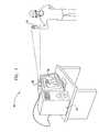
- FIG. 1is a schematic, pictorial illustration of a system for 3D ranging and mapping, in accordance with an embodiment of the present invention
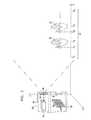
- FIG. 2is a schematic top view of a speckle imaging device, in accordance with an embodiment of the present invention.
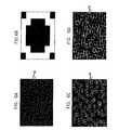
- FIG. 3Ais a schematic representation of a speckle pattern created by projection of a laser beam through a randomizing optical element, in accordance with an embodiment of the present invention
- FIG. 3Bis a schematic representation of a light pattern created by a diffractive optical element (DOE), in accordance with an embodiment of the present invention.
- DOEdiffractive optical element
- FIGS. 3C and 3Dare schematic representations of speckle patterns created by projection of a laser beam through the optical elements of FIGS. 3A and 3B , in accordance with an embodiment of the present invention
- FIG. 4is a flow chart that schematically illustrates a method for 3D ranging and mapping, in accordance with an embodiment of the present invention
- FIGS. 5A-5Pare schematic representations of a set of zone plates at different rotation angles, which are used in creating a DOE, in accordance with an embodiment of the present invention
- FIG. 5Qis a schematic, frontal view of a DOE created by superposing the zone plates of FIGS. 5A-5P , in accordance with an embodiment of the present invention
- FIG. 6Ais a schematic representation of a speckle pattern created by projection of a laser beam through a randomizing optical element, in accordance with an embodiment of the present invention
- FIG. 6Bis a schematic representation of a light pattern created by a diffractive optical element (DOE), in accordance with an embodiment of the present invention.
- DOEdiffractive optical element
- FIGS. 6C and 6Dare schematic representations of speckle patterns created by projection of a laser beam through the optical elements of FIGS. 6A and 6B , in accordance with an embodiment of the present invention.
- FIG. 1is a schematic, pictorial illustration of a system 20 for 3D ranging and mapping, in accordance with, an embodiment of the present invention.
- System 20comprises an imaging device 22 , which generates and projects a pattern of spots onto an object 28 and captures an image of the spot pattern appearing on the object. Details of the design and operation of device 22 are shown in the figures that follow and are described hereinbelow with reference thereto.
- the pattern of spots that is projected by imaging device 22comprises a speckle pattern.
- speckle patternrefers to a projected pattern of bright spots whose positions are uncorrelated in planes transverse to the projection beam axis. The positions are uncorrelated in the sense that the auto-correlation of the positions of the speckles in the pattern as a function of transverse shift is insignificant for any shift larger than the spot size. Random patterns, such as those created by primary laser speckle (as described above), are uncorrelated in this sense. Patterns created by human or computer design, such as pseudo-random and quasi-random patterns, may also be uncorrelated.
- the spotsmay be arranged in a regular, non-random pattern, such as the type of pattern that may be created by passing the illumination beam through a Damman grating or a suitable lenslet array.
- the spot patternhave a low duty cycle, i.e., that the fraction of the area of the pattern with above-average brightness be no greater than 1/e, and desirably less than 1 ⁇ 4 or even 1/10.
- the low duty cycleis advantageous in enhancing the signal/noise ratio of spot shift detection for 3D mapping. It also helps to avoid interference effects that may result when neighboring spots overlap.
- the shapes of the spots in the patterns that are used in embodiments of the present inventionare not entirely random, as in conventional laser speckle patterns, but rather have a common shape characteristic.
- the spotsare elongated along a certain axis.
- the spotsmay have other common shape characteristics, so long as the shapes are controlled, and changes in the shapes as a function of distance along the axis of the illumination beam are identifiable.
- the term “changes of shape” in this contextmeans changes other than the simple linear increase in spot size that normally occurs with distance from the illumination source.
- An image processor 24processes image data generated by device 22 in order to perform depth ranging and, optionally, 3D mapping of object 28 .
- rangingrefers to finding a coarse measure of distance from the imaging device to the object
- 3D maprefers to a set of 3D coordinates representing the surface of the object.
- 3D mappingor equivalently, “3D reconstruction.”
- Both ranging and mappingmay be used together, as coarse and fine phases, in the process of 3D reconstruction, as described hereinbelow. Therefore, ranging may also be considered to be a sort of rough 3D mapping.
- Image processor 24which performs such ranging and mapping, may comprise a general-purpose computer processor, which is programmed in software to carry out the functions described hereinbelow.
- the softwaremay be downloaded to processor 24 in electronic form, over a network, for example, or it may alternatively be provided on tangible media, such as optical, magnetic, or electronic memory media.
- some or all of the functions of the image processormay be implemented in dedicated hardware, such as a custom or semi-custom integrated circuit or a programmable digital signal processor (DSP).
- DSPprogrammable digital signal processor
- processor 24is shown in FIG. 1 , by way of example, as a separate unit from imaging device 22 , some or all of the processing functions of processor 24 may be performed by suitable dedicated circuitry within the housing of the imaging device or otherwise associated with the imaging device.
- the 3D map that is generated by processor 24may be used for a wide range of different purposes.
- the mapmay be sent to an output device, such as a display 26 , which shows a pseudo-3D image of the object.
- object 28comprises all or a part (such as a hand) of the body of a subject.
- system 20may be used to provide a gesture-based user interface, in which user movements detected by means of device 22 control an interactive computer application, such as a game, in place of tactile interface elements such as a mouse, joystick or other accessory.
- system 20may be used to create 3D maps of objects of other types, for substantially any application in which 3D coordinate profiles are needed.
- FIG. 2is a schematic top view of device 22 , in accordance with an embodiment of the present invention.
- An illumination assembly 30 in device 22comprises a coherent light source 34 , typically a laser, and one or more optical elements 36 , 38 , which are typically used in combination to create a speckle pattern or other pattern of spots, as described hereinbelow.
- the term “light” in the context of the present patent applicationrefers to any sort of optical radiation, including infrared and ultraviolet, as well as visible light.
- the beam of light emitted by source 34passes through optical elements 36 and 38 and illuminates a target region 46 in which object 28 is located.
- An image capture assembly 32captures an image of the pattern that is projected onto object 28 .
- Assembly 32comprises objective optics 40 , which focus the image onto an image sensor 42 .
- sensor 40comprises a rectilinear array of detector elements 44 , such as a CCD or CMOS-based image sensor array.
- illumination assembly 30 and image capture assembly 32are held in a fixed spatial relation.
- This configuration and the processing techniques described hereinbelowmake it possible to perform 3D mapping using the single image capture assembly, without relative movement between the illumination and image capture assemblies and without moving parts.
- the techniques of illumination, ranging and mapping that are described hereinbelowmay be used in conjunction with other sorts of image capture assemblies, in various different configurations, such as those described in the Background section above.
- the image capture assemblymay be movable relative to the illumination assembly.
- two or more image capture assembliesmay be used to capture images of object 28 from different angles.
- assemblies 30 and 32may be mounted so that an axis passing through the centers of the entrance pupil of image capture assembly 32 and the spot formed by light source 34 on optical element 36 is parallel to one of the axes of sensor 40 (taken for convenience to be the X-axis, while the Z-axis corresponds to distance from device 22 ).
- a Z-direction shift of a point on the object, ⁇ Zwill engender a concomitant transverse shift ⁇ X in the spot pattern observed in the image.
- Z-coordinates of points on the object, as well as shifts in the Z-coordinates over timemay thus be determined by measuring shifts in the X-coordinates of the spots in the image captured by assembly 32 relative to a reference image taken at a known distance Z.
- Y-direction shiftsmay be disregarded.
- This sort of triangulation approachis appropriate particularly in 3D mapping using speckle patterns, although aspects of the approach may be adapted for use with other types of spot patterns, as well.
- the group of spots in each area of the captured imageis compared to the reference image to find the most closely-matching group of spots in the reference image.
- the relative shift between the matching groups of spots in the imagegives the Z-direction shift of the area of the captured image relative to the reference image.
- the shift in the spot patternmay be measured using image correlation or other image matching computation methods that are known in the art. Some exemplary methods are described in the above-mentioned PCT patent applications.
- Patterns of spots with a common shape characteristicscan be used to enhance the operation of system 20 in a number of ways.
- a pattern of specklesthat are elongated in the Y-direction.
- processor 24computes the correlation between images for the purpose of detecting Z-direction shifts, the computation will be insensitive to small shifts of the speckles in the Y-direction. This feature improves the robustness of the X-direction shift computation (and may make it possible to use a smaller correlation window in the computation).
- optical element 36may be configured as a diffuser, with a randomly-arranged array of grains that are elongated in the X-direction.
- the grainsmay be opaque, for example, or they may alternatively be of different thickness so as to cause phase changes in the transmitted light.
- element 36may comprise a conventional, isotropic diffuser, while the beam from light source 34 is elongated in the X-direction.
- a cylindrical lens (not shown) between the source and diffusermay be used for this purpose, for example.
- element 36comprise a diffuser (which may be isotropic) and element 38 comprise a diffractive optical element (DOE).
- DOEdiffractive optical element
- element 38may simply comprise a suitable grating or zone plate with lines oriented parallel to the X-axis.
- elements 36 and 38are shown in FIG. 2 , for the sake of conceptual clarity, as separate components, the diffuser and DOE are typically in contact with one another and may be glued together. Alternatively, elements 36 and 38 may be made as a single piece, by forming the DOE on one side of an optical blank and grinding the other side to create the diffuser. Further alternatively, the optical constraints imposed by the diffuser and grating or zone plate may be combined in a single DOE, in which the X-oriented lines and a pseudo-random diffusing pattern are superposed, for example. In all of these cases, the pattern of speckles in the far field will be a convolution of the random position distribution provided by the diffuser with the shape defined by the Fourier transform of the DOE.
- the DOEmay be designed to create a pattern of spots having different shapes in different distance ranges.
- the spotsmay have one shape at distance Z 1 , another at Z 2 , and so forth.
- the elongated shape of the spotsmay be rotated by 45° from range to range.
- processor 24FIG. 1
- Ranging and mappingmay be used in combination to generate 3D maps with enhanced range and/or resolution, as described further hereinbelow.
- a set of one or more optical elements for such purposesmay be designed based on a superposition of constraints.
- such an element or elements for generating speckles with four different orientations in different, respective rangesmay be produced by superposing a splitter (which generates a pattern of spots with low duty cycle and uncorrelated positions) with an element that, taken on its own, implements a single Z-varying pattern at four orientations in four predefined ranges.
- the element creating the single patternmay be, for instance, a superposition of four zone plates, each of which focuses light to a line in the proper, respective direction in one of the ranges.
- the superpositionmay be computed and then implemented in a suitable computer-generated hologram (CGH) or other DOE.
- CGHcomputer-generated hologram
- the constraintscan be implemented using two filters P S , F V , corresponding to optical elements 36 and 38 , as follows:
- FIGS. 3A-3Dare schematic representations of images created by projecting a laser beam through DOEs 36 and 38 that are designed in accordance with an embodiment of the present invention.
- the object of this designis to create a pattern of elongated speckles whose axis of elongation varies over 180° as a function of Z over a given range from Z 0 to Z 0 + ⁇ Z.
- FIGS. 3A and 3Bshow the patterns created by F S and F V , respectively, which are defined as follows:
- Optical element 38 implementing this patternmay be designed using the Gerchberg-Saxton method described above, by superposing multiple zone plates as described below, or using any other suitable method of DOE design that is known in the art. Because the pattern is small, the computation required to generate the DOE is relatively simple in any case.
- FIGS. 3C and 3Dshow the pattern of speckles that is created by superposing elements 36 and 38 , corresponding to F S and F V , at two different values of Z.
- ZZ 0 + p N ⁇ ⁇ ⁇ ⁇ Z as the range of the surface from device 22 .
- FIG. 4is a flow chart that schematically illustrates a method for 3D ranging and mapping, in accordance with an embodiment of the present invention. The method is described hereinbelow, for the sake of clarity, with reference to system 20 , as illustrated in FIGS. 1 and 2 , using the speckle pattern shown in FIGS. 3C and 3D . This method may similarly be applied, however, in speckle-based imaging systems of other sorts, such as those described in the references cited above. Furthermore, other sorts of spot patterns and of Z-varying spot shape characteristics may alternatively be created and used in place of the rotating linear shape of the speckles shown in FIGS. 3C and 3D .
- imaging device 22is operated to capture one or more reference speckle images.
- a planar surfacemay be placed at one or more known fiducial distances from the origin along the Z-axis, such as at Z 1 , Z 2 , Z 3 , . . . .
- Imaging assembly 32captures a reference image of the speckle pattern that is projected onto the surface by illumination assembly 30 at each distance.
- the speckle patternis essentially a convolution of the small Z-varying pattern of F V and the far-field spot pattern of F S
- respective reference patternscan be determined separately for the two filters and then convolved to give the combined pattern at each distance Z. This approach can reduce the amount of memory required for storing the reference patterns. Further alternatively, the design of the entire pattern can be standardized, thus rendering the capture of the reference unnecessary.
- Object 28is introduced into target region 46 , and device 22 captures a test image of the speckle pattern that is projected onto the surface of the object, at a test capture step 60 .
- Processor 24then computes the orientation angle of the speckles, at a ranging step 62 .
- the processormay, for example, perform a spectral analysis of the test image.
- the shape of the spectrum(for example, the directions of the major and minor axes) will correspond to the orientation angle of the speckles, which will in turn indicate the range of the object.
- the processormay compute the cross-correlation between the speckle shape and a number of different reference shapes.
- the speckle anglemay vary over the surface, so that different parts of the object will have different ranges.
- Processor 24may identify the loci of any abrupt changes in speckle angle as edges of the object.
- Processor 24may use the shape-based range measurement of step 62 by itself in generating a rough 3D map of object 28 .
- the processoruses this range measurement in conjunction with spot position triangulation in reconstructing the 3D map of object 28 , at a reconstruction step 64 .
- the processortypically measures local offsets between the speckle pattern at different points on the object surface in the test image and corresponding areas of the speckle pattern in the appropriate reference image.
- the processorthen uses triangulation, based on the offsets, to determine the Z-coordinates of these object points.
- the combination of ranging at step 62 with 3D reconstruction at step 64enables system 20 to perform 3D reconstruction with greater precision and/or lower computational cost than can generally be achieved by speckle-based triangulation alone, and may also be used to increase the range in the Z-direction over which the measurement is made. For example, if multiple reference images were captured at different fiducial distances, as mentioned above, the processor can measure the local offsets relative to the reference image whose fiducial distance is closest to the range found at step 62 . Even if only a single reference image is used, the triangulation accuracy and/or speed at step 64 can be enhanced since processor 24 can use the ranging result to limit the number of different local offset values that it has to check or to compute the offset with greater precision.
- Steps 60 - 64may be repeated continually in order to track motion of object 28 within target region 46 .
- device 22captures a succession of test images while the object is moving, and processor 24 repeats steps 62 and 64 in order to track the 3D movement of the object. It may be possible to skip step 62 in some iterations by assuming that the object has not moved too far since the previous iteration.
- triangulation based on shifts of the speckle patternis used for coarse range measurement, and changes in the speckle shape characteristic are used for accurate 3D mapping.
- the accuracy of triangulationdepends, inter alia, on the separation along the X-axis between illumination assembly 30 and image capture assembly 32 . If only coarse triangulation is required, assemblies 30 and 32 can be positioned close together, thus permitting a more compact design of device 22 .
- Enhanced accuracy of the shape-based Z-direction measurementmay be achieved, for example, by replicating the Z-varying pattern of the speckle shape over several cycles within target region 46 .
- the speckle orientationmay vary over 180° between Z 1 and Z 2 , and then again between Z 2 and Z 3 , and again between Z 3 and Z 4 .
- Processor 24uses the speckle triangulation result to decide in which of these three ranges object 28 is located, and then uses the speckle orientations to construct the precise 3D map of the object within this range.
- other Z-varying spot shape characteristicsmay be used in this context in place of the directional variation illustrated in FIGS. 3C and 3D .
- the patternmay be focused onto target region 46 using a suitable multifocal lens (not shown).
- a suitable multifocal lensmay comprise, for example, a superposition of several Fresnel zone plates with different respective focal lengths.
- a suitable multifocal lensmay be designed using techniques described by Ben Eliezer, et al., in “All Optical Extended Depth of Field Imaging System,” Journal of Optica and Pure Physics—A, 5 (2003), pages S164-S169, which is incorporated herein by reference.
- optical element 38may be designed ab initio, using the superposition techniques described above, to give a speckle shape that repeats over multiple cycles.
- FIGS. 5A-5Qschematically illustrate a method for producing optical element 38 so as to create a pattern of shaped spots, in accordance with an embodiment of the present invention.
- FIGS. 5A-5Pare schematic, frontal views of a set of zone plates 70
- FIG. 5Qis a schematic frontal view of a DOE 72 created by superposing the zone plates of FIGS. 5A-5P .
- DOE 72can serve as the filter F V , for use together with a suitable diffuser or other beam splitting filter F S , in order to produce the sort of rotating, linear spots that are shown above in FIGS. 3C and 3D .
- the transmission function of such a zone plateis given by:
- zone plates 70may be designed as transparent, phase-only zone plates.
- DOE 72comprises a superposition 74 of these N zone plates. This superposition will produce a line which rotates as a function of Z at a rate of ⁇ /N(f n ⁇ f n-1 )rad/m.
- the superpositionmay be produced, as shown in FIG. 5Q , as an assemblage of “pie slices” cut from the sixteen component zone plates.
- pieces of the different zone platesmay be extracted at random and assembled to create the superposition.
- the component zone platesmay be summed at each point in DOE 72 to create a single pattern, with appropriate quantization of the summed transmittance or phase shift at each point.
- optical element 38may comprise an array of refractive lenses instead of the zone plates described above.
- a superposition of cylindrical lensessuch as micro-lenses
- a superposition of cylindrical lensesat different orientations, in pie-slice or random distribution, may be used to create the desired Z-varying pattern.
- FIGS. 6A-6Dare schematic representations of images created by projecting a laser beam through DOEs that are designed in accordance with another embodiment of the present invention.
- the examples shown in the preceding embodimentsrelate specifically to patterns of speckles with rotating linear shapes, the principles of the present invention may similarly be applied in creating Z-varying patterns of other types and in optical ranging using such patterns.
- FIGS. 6A-6Dshow one example, in which speckles 80 and 82 have a common morphological characteristic, in the form of a circular or elliptical shape. The radius of the shape of each spot varies with distance from the illumination assembly at a different rate from the linear magnification of the pattern as a whole, thereby providing information on the distance.
- Other sorts of shapes and patternswill be apparent to those skilled in the art and are considered to be within the scope of the present invention.
- FIGS. 6A and 6Bshow the patterns created by F S and F V , respectively.
- F screates a pattern of random speckles 50 , which need not vary in Z.
- F vcreates an annular light intensity pattern in the target region. The radius of the annulus varies with Z in such a fashion as to enable ranging based on the radii of the spots that are observed in the image captured by image capture assembly 32 .
- an optical element implementing this patternmay be designed using the Gerchberg-Saxton method, or by superposing multiple diffractive optical elements that create simple circular or elliptical patterns with different size characteristics, or using any other suitable method of DOE design that is known in the art.
- FIGS. 6C and 6Dshow images of the pattern of speckles that is projected onto a surface by passing coherent light through elements 36 and 38 (corresponding to F S and F V ), with the surface at two different values of Z.
- the imagesare shown as they would be captured by image capture assembly 32 .
- the patternscomprise elliptical speckles 80 and 82 , respectively, with different radii depending on Z.
- the radii of the speckles that are projected onto the surface of object 28 and imaged onto sensor 42increase or decrease at a known rate.
- processoris thus able to determine the range of the surface from device 22 .
- the processormay detect and analyze changes in the shapes of the speckles in order to determine the angular skew of the surface relative to the X-Y plane.
- the embodiments described aboverelate to specifically to speckle shaping and speckle-based 3D ranging and mapping
Landscapes
- Engineering & Computer Science (AREA)
- Physics & Mathematics (AREA)
- Computer Vision & Pattern Recognition (AREA)
- General Physics & Mathematics (AREA)
- Electromagnetism (AREA)
- Multimedia (AREA)
- Signal Processing (AREA)
- Optics & Photonics (AREA)
- Theoretical Computer Science (AREA)
- Length Measuring Devices By Optical Means (AREA)
Abstract
Description

- Filter FScreates intensity pattern S in the far field, meaning it is an appropriate inverse Fourier transform of S (which can be computed using techniques of DOE design that are known in the art).
- Filter FVcreates intensity patterns Pi, i=1, 2, . . . , K at distances Zi, i=1, 2, . . . , K, respectively. Intensity patterns of this sort are generally much simpler to compute than the above-mentioned patterns Ri, i=1, 2, . . . , K, and may generally be created individually using methods known in the art.
The combined filter F=FS·FV(wherein the multiplication is performed pointwise in the filter plane) will implement intensity patterns Ri, i=1, 2, . . . , K at distances Zi, i=1, 2, . . . , K, respectively.
- Fscreates a far-field pattern of random speckles, which need not vary in Z. For example, FSmay be designed to create a pattern of 1000×1000 pixels, comprising 200×200
bright speckles 50, randomly distributed, with the rest of the field dark. Depending on the sizes of the spots, the duty cycle is typically roughly between 4% and 25%.Optical element 36 to implement this pattern may comprise a phase-only DOE, created using techniques that are known in the art. - Fvcreates N light intensity patterns in the near-field volume between the planes Z0and Z0+ΔZ.
FIG. 3B shows one such pattern at a given
- Fscreates a far-field pattern of random speckles, which need not vary in Z. For example, FSmay be designed to create a pattern of 1000×1000 pixels, comprising 200×200
The pattern comprises V×W pixels, wherein V and W are typically small—in this case V=W=5. For each p, p=1, . . . , N, the pattern is rotated by an angle θ=180*p/N relative to the vertical.
as the range of the surface from
wherein the X-Y axes in each zone plate are rotated by (n−1)π/N. Alternatively,

implements Ri=P1i
wherein Ul(x, y, z) is the pattern filter l would create at distance z, and
denotes convolution.
Claims (22)
Priority Applications (1)
| Application Number | Priority Date | Filing Date | Title |
|---|---|---|---|
| US13/043,488US8374397B2 (en) | 2005-10-11 | 2011-03-09 | Depth-varying light fields for three dimensional sensing |
Applications Claiming Priority (6)
| Application Number | Priority Date | Filing Date | Title |
|---|---|---|---|
| US72490305P | 2005-10-11 | 2005-10-11 | |
| PCT/IL2006/000335WO2007043036A1 (en) | 2005-10-11 | 2006-03-14 | Method and system for object reconstruction |
| US78518706P | 2006-03-24 | 2006-03-24 | |
| US85243606P | 2006-10-16 | 2006-10-16 | |
| US11/724,068US8050461B2 (en) | 2005-10-11 | 2007-03-13 | Depth-varying light fields for three dimensional sensing |
| US13/043,488US8374397B2 (en) | 2005-10-11 | 2011-03-09 | Depth-varying light fields for three dimensional sensing |
Related Parent Applications (1)
| Application Number | Title | Priority Date | Filing Date |
|---|---|---|---|
| US11/724,068DivisionUS8050461B2 (en) | 2005-10-11 | 2007-03-13 | Depth-varying light fields for three dimensional sensing |
Publications (2)
| Publication Number | Publication Date |
|---|---|
| US20110158508A1 US20110158508A1 (en) | 2011-06-30 |
| US8374397B2true US8374397B2 (en) | 2013-02-12 |
Family
ID=38509879
Family Applications (1)
| Application Number | Title | Priority Date | Filing Date |
|---|---|---|---|
| US13/043,488ActiveUS8374397B2 (en) | 2005-10-11 | 2011-03-09 | Depth-varying light fields for three dimensional sensing |
Country Status (5)
| Country | Link |
|---|---|
| US (1) | US8374397B2 (en) |
| EP (1) | EP1994503B1 (en) |
| JP (1) | JP5592070B2 (en) |
| CN (1) | CN101501442B (en) |
| WO (1) | WO2007105215A2 (en) |
Cited By (14)
| Publication number | Priority date | Publication date | Assignee | Title |
|---|---|---|---|---|
| US20110188741A1 (en)* | 2009-05-13 | 2011-08-04 | Applied Vision Corporation | System and method for dimensioning objects using stereoscopic imaging |
| US9014903B1 (en)* | 2012-05-22 | 2015-04-21 | Google Inc. | Determination of object heading based on point cloud |
| US20150199562A1 (en)* | 2011-07-12 | 2015-07-16 | Lucasfilm Entertainment Company Ltd. | Scale independent tracking pattern |
| US9984519B2 (en) | 2015-04-10 | 2018-05-29 | Google Llc | Method and system for optical user recognition |
| US10114452B2 (en) | 2015-03-11 | 2018-10-30 | Panasonic Intellectual Property Management Co., Ltd. | Motion detection system |
| US10241244B2 (en) | 2016-07-29 | 2019-03-26 | Lumentum Operations Llc | Thin film total internal reflection diffraction grating for single polarization or dual polarization |
| US10282839B2 (en) | 2012-05-14 | 2019-05-07 | Gauss Surgical, Inc. | System and method for estimating a quantity of a blood component in a fluid canister |
| US10334216B2 (en) | 2014-11-06 | 2019-06-25 | Sony Corporation | Imaging system including lens with longitudinal chromatic aberration, endoscope and imaging method |
| US10424060B2 (en) | 2012-07-09 | 2019-09-24 | Gauss Surgical, Inc. | Method for estimating blood component quantities in surgical textiles |
| US10528782B2 (en) | 2011-07-09 | 2020-01-07 | Gauss Surgical, Inc. | System and method for estimating extracorporeal blood volume in a physical sample |
| US10610133B2 (en) | 2015-11-05 | 2020-04-07 | Google Llc | Using active IR sensor to monitor sleep |
| US10863933B2 (en) | 2012-05-14 | 2020-12-15 | Gauss Surgical, Inc. | System and methods for managing blood loss of a patient |
| US10957179B2 (en) | 2011-07-09 | 2021-03-23 | Gauss Surgical, Inc. | Method for estimating a quantity of a blood component in a fluid receiver and corresponding error |
| US11229368B2 (en) | 2017-01-13 | 2022-01-25 | Gauss Surgical, Inc. | Fluid loss estimation based on weight of medical items |
Families Citing this family (97)
| Publication number | Priority date | Publication date | Assignee | Title |
|---|---|---|---|---|
| WO2007043036A1 (en) | 2005-10-11 | 2007-04-19 | Prime Sense Ltd. | Method and system for object reconstruction |
| US9330324B2 (en) | 2005-10-11 | 2016-05-03 | Apple Inc. | Error compensation in three-dimensional mapping |
| US20110096182A1 (en)* | 2009-10-25 | 2011-04-28 | Prime Sense Ltd | Error Compensation in Three-Dimensional Mapping |
| US8050461B2 (en) | 2005-10-11 | 2011-11-01 | Primesense Ltd. | Depth-varying light fields for three dimensional sensing |
| DK1997046T3 (en)* | 2006-01-11 | 2017-03-13 | Densys Ltd | THREE-DIMENSIONAL MODELING OF THE ORAL |
| KR101331543B1 (en) | 2006-03-14 | 2013-11-20 | 프라임센스 엘티디. | Three-dimensional sensing using speckle patterns |
| US8350847B2 (en) | 2007-01-21 | 2013-01-08 | Primesense Ltd | Depth mapping using multi-beam illumination |
| US8150142B2 (en) | 2007-04-02 | 2012-04-03 | Prime Sense Ltd. | Depth mapping using projected patterns |
| US8493496B2 (en) | 2007-04-02 | 2013-07-23 | Primesense Ltd. | Depth mapping using projected patterns |
| US8494252B2 (en) | 2007-06-19 | 2013-07-23 | Primesense Ltd. | Depth mapping using optical elements having non-uniform focal characteristics |
| FR2921719B1 (en)* | 2007-09-28 | 2010-03-12 | Noomeo | METHOD FOR CONSTRUCTING A SYNTHESIS IMAGE OF A THREE-DIMENSIONAL SURFACE OF A PHYSICAL OBJECT |
| US8488129B2 (en)* | 2007-10-05 | 2013-07-16 | Artec Group, Inc. | Combined object capturing system and display device and associated method |
| DE102007058590B4 (en)* | 2007-12-04 | 2010-09-16 | Sirona Dental Systems Gmbh | Recording method for an image of a recording object and recording device |
| US20110074924A1 (en)* | 2008-06-02 | 2011-03-31 | Koninklijke Philips Electronics N.V. | Video signal with depth information |
| US8456517B2 (en) | 2008-07-09 | 2013-06-04 | Primesense Ltd. | Integrated processor for 3D mapping |
| EP2362963A2 (en)* | 2008-10-06 | 2011-09-07 | Mantisvision Ltd. | Method and system for providing three-dimensional and range inter-planar estimation |
| US8462207B2 (en) | 2009-02-12 | 2013-06-11 | Primesense Ltd. | Depth ranging with Moiré patterns |
| US8786682B2 (en) | 2009-03-05 | 2014-07-22 | Primesense Ltd. | Reference image techniques for three-dimensional sensing |
| US8717417B2 (en) | 2009-04-16 | 2014-05-06 | Primesense Ltd. | Three-dimensional mapping and imaging |
| US9091536B2 (en)* | 2009-06-01 | 2015-07-28 | Dentsply International Inc. | Method and device for three-dimensional surface detection with a dynamic reference frame |
| US8417385B2 (en)* | 2009-07-01 | 2013-04-09 | Pixart Imaging Inc. | Home appliance control device |
| WO2011013079A1 (en) | 2009-07-30 | 2011-02-03 | Primesense Ltd. | Depth mapping based on pattern matching and stereoscopic information |
| KR101809636B1 (en)* | 2009-09-22 | 2018-01-18 | 페이스북, 인크. | Remote control of computer devices |
| JP5588310B2 (en)* | 2009-11-15 | 2014-09-10 | プライムセンス リミテッド | Optical projector with beam monitor |
| US8830227B2 (en) | 2009-12-06 | 2014-09-09 | Primesense Ltd. | Depth-based gain control |
| GB0921461D0 (en)* | 2009-12-08 | 2010-01-20 | Qinetiq Ltd | Range based sensing |
| JP4783456B2 (en)* | 2009-12-22 | 2011-09-28 | 株式会社東芝 | Video playback apparatus and video playback method |
| US20110187878A1 (en)* | 2010-02-02 | 2011-08-04 | Primesense Ltd. | Synchronization of projected illumination with rolling shutter of image sensor |
| US8982182B2 (en) | 2010-03-01 | 2015-03-17 | Apple Inc. | Non-uniform spatial resource allocation for depth mapping |
| CN103097925B (en)* | 2010-08-06 | 2016-04-13 | 旭硝子株式会社 | Diffraction optical element and measuring device |
| WO2012020380A1 (en) | 2010-08-11 | 2012-02-16 | Primesense Ltd. | Scanning projectors and image capture modules for 3d mapping |
| US20120056988A1 (en)* | 2010-09-07 | 2012-03-08 | David Stanhill | 3-d camera |
| US9870068B2 (en) | 2010-09-19 | 2018-01-16 | Facebook, Inc. | Depth mapping with a head mounted display using stereo cameras and structured light |
| EP2643659B1 (en) | 2010-11-19 | 2019-12-25 | Apple Inc. | Depth mapping using time-coded illumination |
| US9167138B2 (en) | 2010-12-06 | 2015-10-20 | Apple Inc. | Pattern projection and imaging using lens arrays |
| US9052512B2 (en) | 2011-03-03 | 2015-06-09 | Asahi Glass Company, Limited | Diffractive optical element and measuring apparatus |
| JP5948949B2 (en)* | 2011-06-28 | 2016-07-06 | 旭硝子株式会社 | Diffractive optical element and measuring device |
| JP5948948B2 (en)* | 2011-03-03 | 2016-07-06 | 旭硝子株式会社 | Diffractive optical element and measuring device |
| US9857868B2 (en) | 2011-03-19 | 2018-01-02 | The Board Of Trustees Of The Leland Stanford Junior University | Method and system for ergonomic touch-free interface |
| US9030528B2 (en) | 2011-04-04 | 2015-05-12 | Apple Inc. | Multi-zone imaging sensor and lens array |
| US8840466B2 (en) | 2011-04-25 | 2014-09-23 | Aquifi, Inc. | Method and system to create three-dimensional mapping in a two-dimensional game |
| US8869073B2 (en)* | 2011-07-28 | 2014-10-21 | Hewlett-Packard Development Company, L.P. | Hand pose interaction |
| US8971572B1 (en) | 2011-08-12 | 2015-03-03 | The Research Foundation For The State University Of New York | Hand pointing estimation for human computer interaction |
| US9518864B2 (en) | 2011-12-15 | 2016-12-13 | Facebook, Inc. | Controllable optical sensing |
| CN102565903B (en)* | 2012-01-11 | 2014-08-13 | 中国科学院上海光学精密机械研究所 | Method for preparing random dammann grating |
| US8854433B1 (en) | 2012-02-03 | 2014-10-07 | Aquifi, Inc. | Method and system enabling natural user interface gestures with an electronic system |
| CN104160240B (en) | 2012-02-15 | 2017-02-22 | 苹果公司 | Scanning depth engine |
| DE102012103766A1 (en)* | 2012-04-27 | 2013-10-31 | Bircher Reglomat Ag | Method for controlling and / or monitoring the areas around resealable building openings |
| US9306999B2 (en) | 2012-06-08 | 2016-04-05 | Unitedhealth Group Incorporated | Interactive sessions with participants and providers |
| US9098739B2 (en) | 2012-06-25 | 2015-08-04 | Aquifi, Inc. | Systems and methods for tracking human hands using parts based template matching |
| US9111135B2 (en) | 2012-06-25 | 2015-08-18 | Aquifi, Inc. | Systems and methods for tracking human hands using parts based template matching using corresponding pixels in bounded regions of a sequence of frames that are a specified distance interval from a reference camera |
| US9933753B2 (en) | 2012-08-01 | 2018-04-03 | Real View Imaging Ltd. | Increasing an area from which reconstruction from a computer generated hologram may be viewed |
| US8836768B1 (en) | 2012-09-04 | 2014-09-16 | Aquifi, Inc. | Method and system enabling natural user interface gestures with user wearable glasses |
| US10234941B2 (en)* | 2012-10-04 | 2019-03-19 | Microsoft Technology Licensing, Llc | Wearable sensor for tracking articulated body-parts |
| GB2507813B (en)* | 2012-11-13 | 2017-06-21 | Focalspec Oy | Apparatus and method for inspecting seals of items |
| CN102970548B (en)* | 2012-11-27 | 2015-01-21 | 西安交通大学 | Image depth sensing device |
| CN103020988B (en)* | 2012-11-27 | 2015-02-25 | 宁波盈芯信息科技有限公司 | Method for generating motion vector of laser speckle image |
| CN102999910B (en)* | 2012-11-27 | 2015-07-22 | 宁波盈芯信息科技有限公司 | Image depth calculating method |
| US9091628B2 (en) | 2012-12-21 | 2015-07-28 | L-3 Communications Security And Detection Systems, Inc. | 3D mapping with two orthogonal imaging views |
| TWI454968B (en) | 2012-12-24 | 2014-10-01 | Ind Tech Res Inst | Three-dimensional interactive device and operation method thereof |
| US9092665B2 (en) | 2013-01-30 | 2015-07-28 | Aquifi, Inc | Systems and methods for initializing motion tracking of human hands |
| US9129155B2 (en) | 2013-01-30 | 2015-09-08 | Aquifi, Inc. | Systems and methods for initializing motion tracking of human hands using template matching within bounded regions determined using a depth map |
| US9298266B2 (en) | 2013-04-02 | 2016-03-29 | Aquifi, Inc. | Systems and methods for implementing three-dimensional (3D) gesture based graphical user interfaces (GUI) that incorporate gesture reactive interface objects |
| US20140307055A1 (en) | 2013-04-15 | 2014-10-16 | Microsoft Corporation | Intensity-modulated light pattern for active stereo |
| WO2014171418A1 (en) | 2013-04-19 | 2014-10-23 | 凸版印刷株式会社 | Three-dimensional shape measurement device, three-dimensional shape measurement method, and three-dimensional shape measurement program |
| US9798388B1 (en) | 2013-07-31 | 2017-10-24 | Aquifi, Inc. | Vibrotactile system to augment 3D input systems |
| US9208566B2 (en)* | 2013-08-09 | 2015-12-08 | Microsoft Technology Licensing, Llc | Speckle sensing for motion tracking |
| KR102027184B1 (en) | 2013-10-23 | 2019-10-01 | 페이스북, 인크. | Three dimensional depth mapping using dynamic structured light |
| WO2015068470A1 (en) | 2013-11-06 | 2015-05-14 | 凸版印刷株式会社 | 3d-shape measurement device, 3d-shape measurement method, and 3d-shape measurement program |
| US10469827B2 (en) | 2013-12-27 | 2019-11-05 | Sony Corporation | Image processing device and image processing method |
| US9507417B2 (en) | 2014-01-07 | 2016-11-29 | Aquifi, Inc. | Systems and methods for implementing head tracking based graphical user interfaces (GUI) that incorporate gesture reactive interface objects |
| US9619105B1 (en) | 2014-01-30 | 2017-04-11 | Aquifi, Inc. | Systems and methods for gesture based interaction with viewpoint dependent user interfaces |
| CN103839258A (en)* | 2014-02-13 | 2014-06-04 | 西安交通大学 | Depth perception method of binarized laser speckle images |
| WO2015152829A1 (en) | 2014-04-03 | 2015-10-08 | Heptagon Micro Optics Pte. Ltd. | Structured-stereo imaging assembly including separate imagers for different wavelengths |
| CN106796661B (en) | 2014-08-12 | 2020-08-25 | 曼蒂斯影像有限公司 | System, method and computer program product for projecting a light pattern |
| USD733141S1 (en) | 2014-09-10 | 2015-06-30 | Faro Technologies, Inc. | Laser scanner |
| US9817159B2 (en)* | 2015-01-31 | 2017-11-14 | Microsoft Technology Licensing, Llc | Structured light pattern generation |
| EP4141793A1 (en) | 2015-02-25 | 2023-03-01 | Facebook Technologies, LLC | Using intensity variations in a light pattern for depth mapping of objects in a volume |
| TWI623889B (en)* | 2015-03-17 | 2018-05-11 | 國立高雄應用科技大學 | 3d hand gesture image recognition method and system thereof |
| KR101904181B1 (en) | 2015-03-22 | 2018-10-04 | 페이스북, 인크. | Depth mapping of head-mounted displays using stereo cameras and structured light |
| US9575183B2 (en)* | 2015-03-31 | 2017-02-21 | The Boeing Company | Tracking measurement system and method |
| US9947098B2 (en)* | 2015-05-13 | 2018-04-17 | Facebook, Inc. | Augmenting a depth map representation with a reflectivity map representation |
| JP6668764B2 (en) | 2016-01-13 | 2020-03-18 | セイコーエプソン株式会社 | Image recognition device, image recognition method, and image recognition unit |
| JP6668763B2 (en) | 2016-01-13 | 2020-03-18 | セイコーエプソン株式会社 | Image recognition device, image recognition method, and image recognition unit |
| JP6631261B2 (en) | 2016-01-14 | 2020-01-15 | セイコーエプソン株式会社 | Image recognition device, image recognition method, and image recognition unit |
| JP6607121B2 (en) | 2016-03-30 | 2019-11-20 | セイコーエプソン株式会社 | Image recognition apparatus, image recognition method, and image recognition unit |
| US10158845B2 (en) | 2017-01-18 | 2018-12-18 | Facebook Technologies, Llc | Tileable structured light projection for wide field-of-view depth sensing |
| EP3602109B1 (en)* | 2017-03-19 | 2021-01-20 | Kovilta Oy | Systems and methods for modulated image capture |
| JP6970376B2 (en) | 2017-12-01 | 2021-11-24 | オムロン株式会社 | Image processing system and image processing method |
| CN108490630B (en)* | 2018-03-12 | 2019-10-22 | Oppo广东移动通信有限公司 | Laser projection module, depth camera and electronic device |
| WO2019165862A1 (en)* | 2018-02-27 | 2019-09-06 | Oppo广东移动通信有限公司 | Laser projection module, depth camera, and electronic device |
| CN108388072B (en)* | 2018-02-27 | 2020-01-10 | Oppo广东移动通信有限公司 | Laser projection module, depth camera and electronic device |
| JP7310809B2 (en) | 2018-06-11 | 2023-07-19 | Agc株式会社 | Diffractive optical element, projection device and measurement device |
| CN112840238B (en) | 2018-10-15 | 2023-08-22 | Agc株式会社 | Diffraction optical element and illumination optical system |
| JP7030757B2 (en)* | 2018-10-23 | 2022-03-07 | ヴァイアヴィ・ソリューションズ・インコーポレイテッド | An optical element including a plurality of regions, an optical system including the optical element, and a method of using the optical system. |
| US11442282B2 (en) | 2018-10-26 | 2022-09-13 | Viavi Solutions Inc. | Optical element including a plurality of regions |
| CN112945141B (en)* | 2021-01-29 | 2023-03-14 | 中北大学 | Structured light rapid imaging method and system based on micro-lens array |
Citations (122)
| Publication number | Priority date | Publication date | Assignee | Title |
|---|---|---|---|---|
| US4336978A (en) | 1978-12-26 | 1982-06-29 | Canon Kabushiki Kaisha | Method for optically making a diffusion plate |
| US4542376A (en) | 1983-11-03 | 1985-09-17 | Burroughs Corporation | System for electronically displaying portions of several different images on a CRT screen through respective prioritized viewports |
| JPS62206684A (en) | 1986-03-07 | 1987-09-11 | Nippon Telegr & Teleph Corp <Ntt> | Position and shape measuring method by pattern projection |
| US4802759A (en) | 1986-08-11 | 1989-02-07 | Goro Matsumoto | Three-dimensional shape measuring apparatus |
| US4843568A (en) | 1986-04-11 | 1989-06-27 | Krueger Myron W | Real time perception of and response to the actions of an unencumbered participant/user |
| US5075562A (en) | 1990-09-20 | 1991-12-24 | Eastman Kodak Company | Method and apparatus for absolute Moire distance measurements using a grating printed on or attached to a surface |
| WO1993003579A1 (en) | 1991-07-26 | 1993-02-18 | Isis Innovation Limited | Three-dimensional vision system |
| US5483261A (en) | 1992-02-14 | 1996-01-09 | Itu Research, Inc. | Graphical input controller and method with rear screen image detection |
| JPH08186845A (en) | 1994-12-27 | 1996-07-16 | Nobuaki Yanagisawa | Focal distance controlling stereoscopic-vision television receiver |
| US5630043A (en) | 1995-05-11 | 1997-05-13 | Cirrus Logic, Inc. | Animated texture map apparatus and method for 3-D image displays |
| US5636025A (en) | 1992-04-23 | 1997-06-03 | Medar, Inc. | System for optically measuring the surface contour of a part using more fringe techniques |
| US5712682A (en) | 1996-04-26 | 1998-01-27 | Intel Corporation | Camera having an adaptive gain control |
| DE19638727A1 (en) | 1996-09-12 | 1998-03-19 | Ruedger Dipl Ing Rubbert | Method for increasing the significance of the three-dimensional measurement of objects |
| WO1998027514A2 (en) | 1996-12-15 | 1998-06-25 | Cognitens, Ltd. | Apparatus and method for 3-dimensional surface geometry reconstruction |
| WO1998028593A1 (en) | 1996-12-20 | 1998-07-02 | Pacific Title And Mirage, Inc. | Apparatus and method for rapid 3d image parametrization |
| US5835218A (en) | 1995-07-18 | 1998-11-10 | Insutrial Technology Institute | Moire interferometry system and method with extended imaging depth |
| US5838428A (en) | 1997-02-28 | 1998-11-17 | United States Of America As Represented By The Secretary Of The Navy | System and method for high resolution range imaging with split light source and pattern mask |
| JPH10327433A (en) | 1997-05-23 | 1998-12-08 | Minolta Co Ltd | Display device for composted image |
| US5856871A (en) | 1993-08-18 | 1999-01-05 | Applied Spectral Imaging Ltd. | Film thickness mapping using interferometric spectral imaging |
| DE19736169A1 (en) | 1997-08-20 | 1999-04-15 | Fhu Hochschule Fuer Technik | Method to measure deformation or vibration using electronic speckle pattern interferometry |
| US5909312A (en) | 1996-10-02 | 1999-06-01 | Ramot University Authority For Applied Research & Industrial Development Ltd. | Phase-only filter for generating an arbitrary illumination pattern |
| US6041140A (en)* | 1994-10-04 | 2000-03-21 | Synthonics, Incorporated | Apparatus for interactive image correlation for three dimensional image production |
| US6081269A (en) | 1992-03-12 | 2000-06-27 | International Business Machines Corporation | Image processing system and method for generating data representing a number of points in a three-dimensional space from a plurality of two-dimensional images of the space |
| US6084712A (en) | 1998-11-03 | 2000-07-04 | Dynamic Measurement And Inspection,Llc | Three dimensional imaging using a refractive optic design |
| US6088105A (en) | 1998-04-04 | 2000-07-11 | Joh. & Ernst Link Gmbh & Co. Kg | Measuring unit for determining dimensions of test pieces, preferably of hollow bodies, in particular, of bores of workpieces, and method for measuring such dimensions |
| US6101269A (en) | 1997-12-19 | 2000-08-08 | Lifef/X Networks, Inc. | Apparatus and method for rapid 3D image parametrization |
| US6100517A (en) | 1995-06-22 | 2000-08-08 | 3Dv Systems Ltd. | Three dimensional camera |
| US6099134A (en) | 1996-09-27 | 2000-08-08 | Hitachi, Ltd. | Liquid crystal display device |
| US6108036A (en) | 1996-03-25 | 2000-08-22 | Sharp Kabushiki Kaisha | Imaging apparatus having a spatial filter and image shifting mechanism controller based on an image mode |
| GB2352901A (en) | 1999-05-12 | 2001-02-07 | Tricorder Technology Plc | Rendering three dimensional representations utilising projected light patterns |
| JP2001141430A (en) | 1999-11-16 | 2001-05-25 | Fuji Photo Film Co Ltd | Image pickup device and image processing device |
| US6259561B1 (en) | 1999-03-26 | 2001-07-10 | The University Of Rochester | Optical system for diffusing light |
| US6262740B1 (en) | 1997-08-01 | 2001-07-17 | Terarecon, Inc. | Method for rendering sections of a volume data set |
| US6268923B1 (en) | 1999-10-07 | 2001-07-31 | Integral Vision, Inc. | Optical method and system for measuring three-dimensional surface topography of an object having a surface contour |
| US6301059B1 (en) | 2000-01-07 | 2001-10-09 | Lucent Technologies Inc. | Astigmatic compensation for an anamorphic optical system |
| US20020041327A1 (en)* | 2000-07-24 | 2002-04-11 | Evan Hildreth | Video-based image control system |
| JP2002122417A (en) | 2000-10-16 | 2002-04-26 | Sumitomo Osaka Cement Co Ltd | Three-dimensional shape measuring device |
| JP2002152776A (en) | 2000-11-09 | 2002-05-24 | Nippon Telegr & Teleph Corp <Ntt> | Range image encoding method and apparatus, and range image decoding method and apparatus |
| US20020075456A1 (en) | 2000-12-20 | 2002-06-20 | Olympus Optical Co., Ltd. | 3D image acquisition apparatus and 3D image acquisition method |
| JP2002213931A (en) | 2001-01-17 | 2002-07-31 | Fuji Xerox Co Ltd | Instrument and method for measuring three-dimensional shape |
| US6494837B2 (en) | 2000-06-10 | 2002-12-17 | Medison Co., Ltd. | System and method for three-dimensional ultrasound imaging using a steerable probe |
| US6495848B1 (en)* | 1998-05-14 | 2002-12-17 | Orametrix, Inc. | Evaluation of projection pattern for transitions in pattern to determine spatial structure of 3D surfaces |
| JP2002365023A (en) | 2001-06-08 | 2002-12-18 | Koji Okamoto | Apparatus and method for measurement of liquid level |
| US20030048237A1 (en) | 2000-02-07 | 2003-03-13 | Seiji Sato | Display system with no eyeglasses |
| US20030057972A1 (en) | 1999-07-26 | 2003-03-27 | Paul Pfaff | Voltage testing and measurement |
| US20030156756A1 (en) | 2002-02-15 | 2003-08-21 | Gokturk Salih Burak | Gesture recognition system using depth perceptive sensors |
| US6686921B1 (en) | 2000-08-01 | 2004-02-03 | International Business Machines Corporation | Method and apparatus for acquiring a set of consistent image maps to represent the color of the surface of an object |
| US6731391B1 (en) | 1998-05-13 | 2004-05-04 | The Research Foundation Of State University Of New York | Shadow moire surface measurement using Talbot effect |
| US6741251B2 (en) | 2001-08-16 | 2004-05-25 | Hewlett-Packard Development Company, L.P. | Method and apparatus for varying focus in a scene |
| US20040105580A1 (en) | 2002-11-22 | 2004-06-03 | Hager Gregory D. | Acquisition of three-dimensional images by an active stereo technique using locally unique patterns |
| US6750906B1 (en) | 1998-05-08 | 2004-06-15 | Cirrus Logic, Inc. | Histogram-based automatic gain control method and system for video applications |
| US6751344B1 (en) | 1999-05-28 | 2004-06-15 | Champion Orthotic Investments, Inc. | Enhanced projector system for machine vision |
| US6754370B1 (en) | 2000-08-14 | 2004-06-22 | The Board Of Trustees Of The Leland Stanford Junior University | Real-time structured light range scanning of moving scenes |
| US20040130730A1 (en) | 2002-11-21 | 2004-07-08 | Michel Cantin | Fast 3D height measurement method and system |
| US20040130790A1 (en) | 2002-09-20 | 2004-07-08 | Sales Tasso R. M. | Random microlens array for optical beam shaping and homogenization |
| US20040174770A1 (en) | 2002-11-27 | 2004-09-09 | Rees Frank L. | Gauss-Rees parametric ultrawideband system |
| US6810135B1 (en) | 2000-06-29 | 2004-10-26 | Trw Inc. | Optimized human presence detection through elimination of background interference |
| US20040213463A1 (en) | 2003-04-22 | 2004-10-28 | Morrison Rick Lee | Multiplexed, spatially encoded illumination system for determining imaging and range estimation |
| US6813440B1 (en) | 2000-10-10 | 2004-11-02 | The Hong Kong Polytechnic University | Body scanner |
| US20040218262A1 (en) | 2003-02-21 | 2004-11-04 | Chuang Yung-Ho | Inspection system using small catadioptric objective |
| US20040228519A1 (en) | 2003-03-10 | 2004-11-18 | Cranial Technologies, Inc. | Automatic selection of cranial remodeling device trim lines |
| US6825985B2 (en) | 2001-07-13 | 2004-11-30 | Mems Optical, Inc. | Autostereoscopic display with rotated microlens and method of displaying multidimensional images, especially color images |
| US6841780B2 (en) | 2001-01-19 | 2005-01-11 | Honeywell International Inc. | Method and apparatus for detecting objects |
| WO2005010825A2 (en) | 2003-07-24 | 2005-02-03 | Cognitens Ltd. | Method and sytem for the three-dimensional surface reconstruction of an object |
| US20050052637A1 (en) | 2003-09-10 | 2005-03-10 | Shaw Eugene L. | Tire inspection apparatus and method |
| US20050111705A1 (en) | 2003-08-26 | 2005-05-26 | Roman Waupotitsch | Passive stereo sensing for 3D facial shape biometrics |
| US6937348B2 (en) | 2000-01-28 | 2005-08-30 | Genex Technologies, Inc. | Method and apparatus for generating structural pattern illumination |
| US20050200925A1 (en) | 1999-12-10 | 2005-09-15 | Xyz Imaging, Inc. | Holographic printer |
| US20050200838A1 (en) | 2003-09-10 | 2005-09-15 | Shaw Eugene L. | Plurality of light sources for inspection apparatus and method |
| US20050231465A1 (en)* | 2004-04-15 | 2005-10-20 | Depue Marshall T | Optical device that measures distance between the device and a surface |
| US20050271279A1 (en) | 2004-05-14 | 2005-12-08 | Honda Motor Co., Ltd. | Sign based human-machine interaction |
| US20060017656A1 (en) | 2004-07-26 | 2006-01-26 | Visteon Global Technologies, Inc. | Image intensity control in overland night vision systems |
| US7006952B1 (en)* | 1999-02-19 | 2006-02-28 | Sanyo Electric Co., Ltd. | 3-D model providing device |
| US20060072851A1 (en) | 2002-06-15 | 2006-04-06 | Microsoft Corporation | Deghosting mosaics using multiperspective plane sweep |
| JP2006128818A (en) | 2004-10-26 | 2006-05-18 | Victor Co Of Japan Ltd | Recording program and reproducing program corresponding to stereoscopic video and 3d audio, recording apparatus, reproducing apparatus and recording medium |
| US7076024B2 (en) | 2004-12-01 | 2006-07-11 | Jordan Valley Applied Radiation, Ltd. | X-ray apparatus with dual monochromators |
| US20060156756A1 (en) | 2005-01-20 | 2006-07-20 | Becke Paul E | Phase change and insulating properties container and method of use |
| US7112774B2 (en) | 2003-10-09 | 2006-09-26 | Avago Technologies Sensor Ip (Singapore) Pte. Ltd | CMOS stereo imaging system and method |
| US20060221218A1 (en) | 2005-04-05 | 2006-10-05 | Doron Adler | Image sensor with improved color filter |
| US7120228B2 (en) | 2004-09-21 | 2006-10-10 | Jordan Valley Applied Radiation Ltd. | Combined X-ray reflectometer and diffractometer |
| US20070060336A1 (en) | 2003-09-15 | 2007-03-15 | Sony Computer Entertainment Inc. | Methods and systems for enabling depth and direction detection when interfacing with a computer program |
| US7194105B2 (en) | 2002-10-16 | 2007-03-20 | Hersch Roger D | Authentication of documents and articles by moiré patterns |
| US20070165243A1 (en)* | 2004-02-09 | 2007-07-19 | Cheol-Gwon Kang | Device for measuring 3d shape using irregular pattern and method for the same |
| US7256899B1 (en) | 2006-10-04 | 2007-08-14 | Ivan Faul | Wireless methods and systems for three-dimensional non-contact shape sensing |
| US20080031513A1 (en)* | 2000-07-14 | 2008-02-07 | Massachusetts Institute Of Technology | Method and system for high resolution, ultra fast 3-D imaging |
| US7335898B2 (en) | 2004-07-23 | 2008-02-26 | Ge Healthcare Niagara Inc. | Method and apparatus for fluorescent confocal microscopy |
| US7369685B2 (en) | 2002-04-05 | 2008-05-06 | Identix Corporation | Vision-based operating method and system |
| US20080106746A1 (en) | 2005-10-11 | 2008-05-08 | Alexander Shpunt | Depth-varying light fields for three dimensional sensing |
| US7385708B2 (en) | 2002-06-07 | 2008-06-10 | The University Of North Carolina At Chapel Hill | Methods and systems for laser based real-time structured light depth extraction |
| US20080198355A1 (en) | 2006-12-27 | 2008-08-21 | Cambridge Research & Instrumentation, Inc | Surface measurement of in-vivo subjects using spot projector |
| US20080212835A1 (en) | 2007-03-01 | 2008-09-04 | Amon Tavor | Object Tracking by 3-Dimensional Modeling |
| US20080240502A1 (en) | 2007-04-02 | 2008-10-02 | Barak Freedman | Depth mapping using projected patterns |
| US7433024B2 (en) | 2006-02-27 | 2008-10-07 | Prime Sense Ltd. | Range mapping using speckle decorrelation |
| US20080247670A1 (en) | 2007-04-03 | 2008-10-09 | Wa James Tam | Generation of a depth map from a monoscopic color image for rendering stereoscopic still and video images |
| US20090096783A1 (en) | 2005-10-11 | 2009-04-16 | Alexander Shpunt | Three-dimensional sensing using speckle patterns |
| US20090183152A1 (en) | 2008-01-16 | 2009-07-16 | Dell Products, Lp | Method to Dynamically Provision Additional Computer Resources to Handle Peak Database Workloads |
| US20090183125A1 (en) | 2008-01-14 | 2009-07-16 | Prime Sense Ltd. | Three-dimensional user interface |
| US20090185274A1 (en) | 2008-01-21 | 2009-07-23 | Prime Sense Ltd. | Optical designs for zero order reduction |
| US20100007717A1 (en) | 2008-07-09 | 2010-01-14 | Prime Sense Ltd | Integrated processor for 3d mapping |
| US20100013860A1 (en) | 2006-03-08 | 2010-01-21 | Electronic Scripting Products, Inc. | Computer interface employing a manipulated object with absolute pose detection component and a display |
| US20100020078A1 (en) | 2007-01-21 | 2010-01-28 | Prime Sense Ltd | Depth mapping using multi-beam illumination |
| US7659995B2 (en) | 2000-09-13 | 2010-02-09 | NextPat, Ltd. | Digitizer using plural capture methods to image features of 3-D objects |
| US7700904B2 (en) | 2007-07-18 | 2010-04-20 | Funai Electric Co., Ltd. | Compound-eye imaging device |
| US20100118123A1 (en) | 2007-04-02 | 2010-05-13 | Prime Sense Ltd | Depth mapping using projected patterns |
| US20100128221A1 (en) | 2006-05-31 | 2010-05-27 | Indiana University Research And Technology Corporation | Laser scanning digital camera with pupil periphery illumination and potential for multiply scattered light imaging |
| US7751063B2 (en) | 2005-04-06 | 2010-07-06 | Dimensional Photonics International, Inc. | Multiple channel interferometric surface contour measurement system |
| US20100177164A1 (en) | 2005-10-11 | 2010-07-15 | Zeev Zalevsky | Method and System for Object Reconstruction |
| US20100194745A1 (en)* | 2007-09-17 | 2010-08-05 | Seereal Technologies S.A. | Holographic Display Having Improved Reconstruction Quality |
| US20100201811A1 (en) | 2009-02-12 | 2010-08-12 | Prime Sense Ltd. | Depth ranging with moire patterns |
| US20100225746A1 (en) | 2009-03-05 | 2010-09-09 | Prime Sense Ltd | Reference image techniques for three-dimensional sensing |
| US20100265316A1 (en) | 2009-04-16 | 2010-10-21 | Primesense Ltd. | Three-dimensional mapping and imaging |
| US20100284082A1 (en) | 2008-01-21 | 2010-11-11 | Primesense Ltd. | Optical pattern projection |
| US20100290698A1 (en) | 2007-06-19 | 2010-11-18 | Prime Sense Ltd | Distance-Varying Illumination and Imaging Techniques for Depth Mapping |
| US7840031B2 (en) | 2007-01-12 | 2010-11-23 | International Business Machines Corporation | Tracking a range of body movement based on 3D captured image streams of a user |
| US20100303289A1 (en) | 2009-05-29 | 2010-12-02 | Microsoft Corporation | Device for identifying and tracking multiple humans over time |
| US20110025827A1 (en) | 2009-07-30 | 2011-02-03 | Primesense Ltd. | Depth Mapping Based on Pattern Matching and Stereoscopic Information |
| US20110074932A1 (en) | 2009-08-27 | 2011-03-31 | California Institute Of Technology | Accurate 3D Object Reconstruction Using a Handheld Device with a Projected Light Pattern |
| US20110096182A1 (en) | 2009-10-25 | 2011-04-28 | Prime Sense Ltd | Error Compensation in Three-Dimensional Mapping |
| US20110134114A1 (en) | 2009-12-06 | 2011-06-09 | Primesense Ltd. | Depth-based gain control |
| US20110188054A1 (en) | 2010-02-02 | 2011-08-04 | Primesense Ltd | Integrated photonics module for optical projection |
| US20110187878A1 (en) | 2010-02-02 | 2011-08-04 | Primesense Ltd. | Synchronization of projected illumination with rolling shutter of image sensor |
| US20110211044A1 (en) | 2010-03-01 | 2011-09-01 | Primesense Ltd. | Non-Uniform Spatial Resource Allocation for Depth Mapping |
Family Cites Families (9)
| Publication number | Priority date | Publication date | Assignee | Title |
|---|---|---|---|---|
| JPS5588002A (en)* | 1978-12-26 | 1980-07-03 | Canon Inc | Optical making method of diffusion plate |
| JPS6079108U (en)* | 1983-11-08 | 1985-06-01 | オムロン株式会社 | speckle rangefinder |
| JPH01240863A (en)* | 1988-03-23 | 1989-09-26 | Kowa Co | Speckle pattern generation method and device |
| JP2714152B2 (en)* | 1989-06-28 | 1998-02-16 | 古野電気株式会社 | Object shape measurement method |
| JP2673196B2 (en)* | 1989-10-13 | 1997-11-05 | 株式会社小野測器 | 3D shape sensor |
| US5003166A (en)* | 1989-11-07 | 1991-03-26 | Massachusetts Institute Of Technology | Multidimensional range mapping with pattern projection and cross correlation |
| US6377353B1 (en)* | 2000-03-07 | 2002-04-23 | Pheno Imaging, Inc. | Three-dimensional measuring system for animals using structured light |
| FR2842591B1 (en)* | 2002-07-16 | 2004-10-22 | Ecole Nale Sup Artes Metiers | DEVICE FOR MEASURING VARIATIONS IN THE RELIEF OF AN OBJECT |
| FR2849245B1 (en)* | 2002-12-20 | 2006-02-24 | Thales Sa | METHOD FOR AUTHENTICATION AND OPTICAL IDENTIFICATION OF OBJECTS AND DEVICE FOR IMPLEMENTING THE SAME |
- 2007
- 2007-03-13CNCN200780009053.8Apatent/CN101501442B/enactiveActive
- 2007-03-13EPEP07713347.8Apatent/EP1994503B1/enactiveActive
- 2007-03-13JPJP2008558984Apatent/JP5592070B2/enactiveActive
- 2007-03-13WOPCT/IL2007/000327patent/WO2007105215A2/enactiveApplication Filing
- 2011
- 2011-03-09USUS13/043,488patent/US8374397B2/enactiveActive
Patent Citations (135)
| Publication number | Priority date | Publication date | Assignee | Title |
|---|---|---|---|---|
| US4336978A (en) | 1978-12-26 | 1982-06-29 | Canon Kabushiki Kaisha | Method for optically making a diffusion plate |
| US4542376A (en) | 1983-11-03 | 1985-09-17 | Burroughs Corporation | System for electronically displaying portions of several different images on a CRT screen through respective prioritized viewports |
| JPS62206684A (en) | 1986-03-07 | 1987-09-11 | Nippon Telegr & Teleph Corp <Ntt> | Position and shape measuring method by pattern projection |
| US4843568A (en) | 1986-04-11 | 1989-06-27 | Krueger Myron W | Real time perception of and response to the actions of an unencumbered participant/user |
| US4802759A (en) | 1986-08-11 | 1989-02-07 | Goro Matsumoto | Three-dimensional shape measuring apparatus |
| US5075562A (en) | 1990-09-20 | 1991-12-24 | Eastman Kodak Company | Method and apparatus for absolute Moire distance measurements using a grating printed on or attached to a surface |
| WO1993003579A1 (en) | 1991-07-26 | 1993-02-18 | Isis Innovation Limited | Three-dimensional vision system |
| US5483261A (en) | 1992-02-14 | 1996-01-09 | Itu Research, Inc. | Graphical input controller and method with rear screen image detection |
| US6081269A (en) | 1992-03-12 | 2000-06-27 | International Business Machines Corporation | Image processing system and method for generating data representing a number of points in a three-dimensional space from a plurality of two-dimensional images of the space |
| US5636025A (en) | 1992-04-23 | 1997-06-03 | Medar, Inc. | System for optically measuring the surface contour of a part using more fringe techniques |
| US5856871A (en) | 1993-08-18 | 1999-01-05 | Applied Spectral Imaging Ltd. | Film thickness mapping using interferometric spectral imaging |
| US6041140A (en)* | 1994-10-04 | 2000-03-21 | Synthonics, Incorporated | Apparatus for interactive image correlation for three dimensional image production |
| JPH08186845A (en) | 1994-12-27 | 1996-07-16 | Nobuaki Yanagisawa | Focal distance controlling stereoscopic-vision television receiver |
| US5630043A (en) | 1995-05-11 | 1997-05-13 | Cirrus Logic, Inc. | Animated texture map apparatus and method for 3-D image displays |
| US6100517A (en) | 1995-06-22 | 2000-08-08 | 3Dv Systems Ltd. | Three dimensional camera |
| US5835218A (en) | 1995-07-18 | 1998-11-10 | Insutrial Technology Institute | Moire interferometry system and method with extended imaging depth |
| US6108036A (en) | 1996-03-25 | 2000-08-22 | Sharp Kabushiki Kaisha | Imaging apparatus having a spatial filter and image shifting mechanism controller based on an image mode |
| US5712682A (en) | 1996-04-26 | 1998-01-27 | Intel Corporation | Camera having an adaptive gain control |
| DE19638727A1 (en) | 1996-09-12 | 1998-03-19 | Ruedger Dipl Ing Rubbert | Method for increasing the significance of the three-dimensional measurement of objects |
| US6099134A (en) | 1996-09-27 | 2000-08-08 | Hitachi, Ltd. | Liquid crystal display device |
| US5909312A (en) | 1996-10-02 | 1999-06-01 | Ramot University Authority For Applied Research & Industrial Development Ltd. | Phase-only filter for generating an arbitrary illumination pattern |
| US20010016063A1 (en)* | 1996-12-15 | 2001-08-23 | Cognitens, Ltd. | Apparatus and method for 3-dimensional surface geometry reconstruction |
| US6167151A (en) | 1996-12-15 | 2000-12-26 | Cognitens, Ltd. | Apparatus and method for 3-dimensional surface geometry reconstruction |
| US6438263B2 (en) | 1996-12-15 | 2002-08-20 | Dan Albeck | Apparatus and method for 3-dimensional surface geometry reconstruction |
| WO1998027514A2 (en) | 1996-12-15 | 1998-06-25 | Cognitens, Ltd. | Apparatus and method for 3-dimensional surface geometry reconstruction |
| WO1998028593A1 (en) | 1996-12-20 | 1998-07-02 | Pacific Title And Mirage, Inc. | Apparatus and method for rapid 3d image parametrization |
| US5838428A (en) | 1997-02-28 | 1998-11-17 | United States Of America As Represented By The Secretary Of The Navy | System and method for high resolution range imaging with split light source and pattern mask |
| JPH10327433A (en) | 1997-05-23 | 1998-12-08 | Minolta Co Ltd | Display device for composted image |
| US6262740B1 (en) | 1997-08-01 | 2001-07-17 | Terarecon, Inc. | Method for rendering sections of a volume data set |
| DE19736169A1 (en) | 1997-08-20 | 1999-04-15 | Fhu Hochschule Fuer Technik | Method to measure deformation or vibration using electronic speckle pattern interferometry |
| US6101269A (en) | 1997-12-19 | 2000-08-08 | Lifef/X Networks, Inc. | Apparatus and method for rapid 3D image parametrization |
| US6088105A (en) | 1998-04-04 | 2000-07-11 | Joh. & Ernst Link Gmbh & Co. Kg | Measuring unit for determining dimensions of test pieces, preferably of hollow bodies, in particular, of bores of workpieces, and method for measuring such dimensions |
| US6750906B1 (en) | 1998-05-08 | 2004-06-15 | Cirrus Logic, Inc. | Histogram-based automatic gain control method and system for video applications |
| US6731391B1 (en) | 1998-05-13 | 2004-05-04 | The Research Foundation Of State University Of New York | Shadow moire surface measurement using Talbot effect |
| US6495848B1 (en)* | 1998-05-14 | 2002-12-17 | Orametrix, Inc. | Evaluation of projection pattern for transitions in pattern to determine spatial structure of 3D surfaces |
| US6084712A (en) | 1998-11-03 | 2000-07-04 | Dynamic Measurement And Inspection,Llc | Three dimensional imaging using a refractive optic design |
| US7006952B1 (en)* | 1999-02-19 | 2006-02-28 | Sanyo Electric Co., Ltd. | 3-D model providing device |
| US6259561B1 (en) | 1999-03-26 | 2001-07-10 | The University Of Rochester | Optical system for diffusing light |
| GB2352901A (en) | 1999-05-12 | 2001-02-07 | Tricorder Technology Plc | Rendering three dimensional representations utilising projected light patterns |
| US6751344B1 (en) | 1999-05-28 | 2004-06-15 | Champion Orthotic Investments, Inc. | Enhanced projector system for machine vision |
| US20030057972A1 (en) | 1999-07-26 | 2003-03-27 | Paul Pfaff | Voltage testing and measurement |
| US6803777B2 (en) | 1999-07-26 | 2004-10-12 | Paul Pfaff | Voltage testing and measurement |
| US6268923B1 (en) | 1999-10-07 | 2001-07-31 | Integral Vision, Inc. | Optical method and system for measuring three-dimensional surface topography of an object having a surface contour |
| JP2001141430A (en) | 1999-11-16 | 2001-05-25 | Fuji Photo Film Co Ltd | Image pickup device and image processing device |
| US20050200925A1 (en) | 1999-12-10 | 2005-09-15 | Xyz Imaging, Inc. | Holographic printer |
| US7009742B2 (en) | 1999-12-10 | 2006-03-07 | Xyz Imaging, Inc. | Holographic printer |
| US6301059B1 (en) | 2000-01-07 | 2001-10-09 | Lucent Technologies Inc. | Astigmatic compensation for an anamorphic optical system |
| US6937348B2 (en) | 2000-01-28 | 2005-08-30 | Genex Technologies, Inc. | Method and apparatus for generating structural pattern illumination |
| US20030048237A1 (en) | 2000-02-07 | 2003-03-13 | Seiji Sato | Display system with no eyeglasses |
| US6494837B2 (en) | 2000-06-10 | 2002-12-17 | Medison Co., Ltd. | System and method for three-dimensional ultrasound imaging using a steerable probe |
| US6810135B1 (en) | 2000-06-29 | 2004-10-26 | Trw Inc. | Optimized human presence detection through elimination of background interference |
| US20080031513A1 (en)* | 2000-07-14 | 2008-02-07 | Massachusetts Institute Of Technology | Method and system for high resolution, ultra fast 3-D imaging |
| US20090016642A1 (en)* | 2000-07-14 | 2009-01-15 | Massachusetts Institute Of Technology | Method and system for high resolution, ultra fast 3-d imaging |
| US20080018595A1 (en) | 2000-07-24 | 2008-01-24 | Gesturetek, Inc. | Video-based image control system |
| US20020041327A1 (en)* | 2000-07-24 | 2002-04-11 | Evan Hildreth | Video-based image control system |
| US6686921B1 (en) | 2000-08-01 | 2004-02-03 | International Business Machines Corporation | Method and apparatus for acquiring a set of consistent image maps to represent the color of the surface of an object |
| US6754370B1 (en) | 2000-08-14 | 2004-06-22 | The Board Of Trustees Of The Leland Stanford Junior University | Real-time structured light range scanning of moving scenes |
| US7659995B2 (en) | 2000-09-13 | 2010-02-09 | NextPat, Ltd. | Digitizer using plural capture methods to image features of 3-D objects |
| US6813440B1 (en) | 2000-10-10 | 2004-11-02 | The Hong Kong Polytechnic University | Body scanner |
| JP2002122417A (en) | 2000-10-16 | 2002-04-26 | Sumitomo Osaka Cement Co Ltd | Three-dimensional shape measuring device |
| JP2002152776A (en) | 2000-11-09 | 2002-05-24 | Nippon Telegr & Teleph Corp <Ntt> | Range image encoding method and apparatus, and range image decoding method and apparatus |
| US7013040B2 (en) | 2000-12-20 | 2006-03-14 | Olympus Optical Co., Ltd. | 3D image acquisition apparatus and 3D image acquisition method |
| US20020075456A1 (en) | 2000-12-20 | 2002-06-20 | Olympus Optical Co., Ltd. | 3D image acquisition apparatus and 3D image acquisition method |
| JP2002213931A (en) | 2001-01-17 | 2002-07-31 | Fuji Xerox Co Ltd | Instrument and method for measuring three-dimensional shape |
| US6841780B2 (en) | 2001-01-19 | 2005-01-11 | Honeywell International Inc. | Method and apparatus for detecting objects |
| JP2002365023A (en) | 2001-06-08 | 2002-12-18 | Koji Okamoto | Apparatus and method for measurement of liquid level |
| US6825985B2 (en) | 2001-07-13 | 2004-11-30 | Mems Optical, Inc. | Autostereoscopic display with rotated microlens and method of displaying multidimensional images, especially color images |
| US6741251B2 (en) | 2001-08-16 | 2004-05-25 | Hewlett-Packard Development Company, L.P. | Method and apparatus for varying focus in a scene |
| US20030156756A1 (en) | 2002-02-15 | 2003-08-21 | Gokturk Salih Burak | Gesture recognition system using depth perceptive sensors |
| US7369685B2 (en) | 2002-04-05 | 2008-05-06 | Identix Corporation | Vision-based operating method and system |
| US7385708B2 (en) | 2002-06-07 | 2008-06-10 | The University Of North Carolina At Chapel Hill | Methods and systems for laser based real-time structured light depth extraction |
| US20060072851A1 (en) | 2002-06-15 | 2006-04-06 | Microsoft Corporation | Deghosting mosaics using multiperspective plane sweep |
| US6859326B2 (en) | 2002-09-20 | 2005-02-22 | Corning Incorporated | Random microlens array for optical beam shaping and homogenization |
| US20040130790A1 (en) | 2002-09-20 | 2004-07-08 | Sales Tasso R. M. | Random microlens array for optical beam shaping and homogenization |
| US7194105B2 (en) | 2002-10-16 | 2007-03-20 | Hersch Roger D | Authentication of documents and articles by moiré patterns |
| US20040130730A1 (en) | 2002-11-21 | 2004-07-08 | Michel Cantin | Fast 3D height measurement method and system |
| US20040105580A1 (en) | 2002-11-22 | 2004-06-03 | Hager Gregory D. | Acquisition of three-dimensional images by an active stereo technique using locally unique patterns |
| US20040174770A1 (en) | 2002-11-27 | 2004-09-09 | Rees Frank L. | Gauss-Rees parametric ultrawideband system |
| US20040218262A1 (en) | 2003-02-21 | 2004-11-04 | Chuang Yung-Ho | Inspection system using small catadioptric objective |
| US20040228519A1 (en) | 2003-03-10 | 2004-11-18 | Cranial Technologies, Inc. | Automatic selection of cranial remodeling device trim lines |
| US7127101B2 (en) | 2003-03-10 | 2006-10-24 | Cranul Technologies, Inc. | Automatic selection of cranial remodeling device trim lines |
| US20040213463A1 (en) | 2003-04-22 | 2004-10-28 | Morrison Rick Lee | Multiplexed, spatially encoded illumination system for determining imaging and range estimation |
| WO2005010825A2 (en) | 2003-07-24 | 2005-02-03 | Cognitens Ltd. | Method and sytem for the three-dimensional surface reconstruction of an object |
| US20070057946A1 (en) | 2003-07-24 | 2007-03-15 | Dan Albeck | Method and system for the three-dimensional surface reconstruction of an object |
| US20050111705A1 (en) | 2003-08-26 | 2005-05-26 | Roman Waupotitsch | Passive stereo sensing for 3D facial shape biometrics |
| US20050200838A1 (en) | 2003-09-10 | 2005-09-15 | Shaw Eugene L. | Plurality of light sources for inspection apparatus and method |
| US20050052637A1 (en) | 2003-09-10 | 2005-03-10 | Shaw Eugene L. | Tire inspection apparatus and method |
| US20070060336A1 (en) | 2003-09-15 | 2007-03-15 | Sony Computer Entertainment Inc. | Methods and systems for enabling depth and direction detection when interfacing with a computer program |
| US7112774B2 (en) | 2003-10-09 | 2006-09-26 | Avago Technologies Sensor Ip (Singapore) Pte. Ltd | CMOS stereo imaging system and method |
| US20070165243A1 (en)* | 2004-02-09 | 2007-07-19 | Cheol-Gwon Kang | Device for measuring 3d shape using irregular pattern and method for the same |
| US20050231465A1 (en)* | 2004-04-15 | 2005-10-20 | Depue Marshall T | Optical device that measures distance between the device and a surface |
| US20050271279A1 (en) | 2004-05-14 | 2005-12-08 | Honda Motor Co., Ltd. | Sign based human-machine interaction |
| US7335898B2 (en) | 2004-07-23 | 2008-02-26 | Ge Healthcare Niagara Inc. | Method and apparatus for fluorescent confocal microscopy |
| US20060017656A1 (en) | 2004-07-26 | 2006-01-26 | Visteon Global Technologies, Inc. | Image intensity control in overland night vision systems |
| US7120228B2 (en) | 2004-09-21 | 2006-10-10 | Jordan Valley Applied Radiation Ltd. | Combined X-ray reflectometer and diffractometer |
| US7551719B2 (en) | 2004-09-21 | 2009-06-23 | Jordan Valley Semiconductord Ltd | Multifunction X-ray analysis system |
| JP2006128818A (en) | 2004-10-26 | 2006-05-18 | Victor Co Of Japan Ltd | Recording program and reproducing program corresponding to stereoscopic video and 3d audio, recording apparatus, reproducing apparatus and recording medium |
| US7076024B2 (en) | 2004-12-01 | 2006-07-11 | Jordan Valley Applied Radiation, Ltd. | X-ray apparatus with dual monochromators |
| US20060156756A1 (en) | 2005-01-20 | 2006-07-20 | Becke Paul E | Phase change and insulating properties container and method of use |
| US20060221218A1 (en) | 2005-04-05 | 2006-10-05 | Doron Adler | Image sensor with improved color filter |
| US7751063B2 (en) | 2005-04-06 | 2010-07-06 | Dimensional Photonics International, Inc. | Multiple channel interferometric surface contour measurement system |
| US20100177164A1 (en) | 2005-10-11 | 2010-07-15 | Zeev Zalevsky | Method and System for Object Reconstruction |
| US8050461B2 (en)* | 2005-10-11 | 2011-11-01 | Primesense Ltd. | Depth-varying light fields for three dimensional sensing |
| US20090096783A1 (en) | 2005-10-11 | 2009-04-16 | Alexander Shpunt | Three-dimensional sensing using speckle patterns |
| US20080106746A1 (en) | 2005-10-11 | 2008-05-08 | Alexander Shpunt | Depth-varying light fields for three dimensional sensing |
| US7433024B2 (en) | 2006-02-27 | 2008-10-07 | Prime Sense Ltd. | Range mapping using speckle decorrelation |
| US20100013860A1 (en) | 2006-03-08 | 2010-01-21 | Electronic Scripting Products, Inc. | Computer interface employing a manipulated object with absolute pose detection component and a display |
| US20100128221A1 (en) | 2006-05-31 | 2010-05-27 | Indiana University Research And Technology Corporation | Laser scanning digital camera with pupil periphery illumination and potential for multiply scattered light imaging |
| US7256899B1 (en) | 2006-10-04 | 2007-08-14 | Ivan Faul | Wireless methods and systems for three-dimensional non-contact shape sensing |
| US20080198355A1 (en) | 2006-12-27 | 2008-08-21 | Cambridge Research & Instrumentation, Inc | Surface measurement of in-vivo subjects using spot projector |
| US7840031B2 (en) | 2007-01-12 | 2010-11-23 | International Business Machines Corporation | Tracking a range of body movement based on 3D captured image streams of a user |
| US20100020078A1 (en) | 2007-01-21 | 2010-01-28 | Prime Sense Ltd | Depth mapping using multi-beam illumination |
| US20080212835A1 (en) | 2007-03-01 | 2008-09-04 | Amon Tavor | Object Tracking by 3-Dimensional Modeling |
| US20100118123A1 (en) | 2007-04-02 | 2010-05-13 | Prime Sense Ltd | Depth mapping using projected patterns |
| US20080240502A1 (en) | 2007-04-02 | 2008-10-02 | Barak Freedman | Depth mapping using projected patterns |
| US20080247670A1 (en) | 2007-04-03 | 2008-10-09 | Wa James Tam | Generation of a depth map from a monoscopic color image for rendering stereoscopic still and video images |
| US20100290698A1 (en) | 2007-06-19 | 2010-11-18 | Prime Sense Ltd | Distance-Varying Illumination and Imaging Techniques for Depth Mapping |
| US7700904B2 (en) | 2007-07-18 | 2010-04-20 | Funai Electric Co., Ltd. | Compound-eye imaging device |
| US20100194745A1 (en)* | 2007-09-17 | 2010-08-05 | Seereal Technologies S.A. | Holographic Display Having Improved Reconstruction Quality |
| US20090183125A1 (en) | 2008-01-14 | 2009-07-16 | Prime Sense Ltd. | Three-dimensional user interface |
| US20090183152A1 (en) | 2008-01-16 | 2009-07-16 | Dell Products, Lp | Method to Dynamically Provision Additional Computer Resources to Handle Peak Database Workloads |
| US20100284082A1 (en) | 2008-01-21 | 2010-11-11 | Primesense Ltd. | Optical pattern projection |
| US20090185274A1 (en) | 2008-01-21 | 2009-07-23 | Prime Sense Ltd. | Optical designs for zero order reduction |
| US20100007717A1 (en) | 2008-07-09 | 2010-01-14 | Prime Sense Ltd | Integrated processor for 3d mapping |
| US20100201811A1 (en) | 2009-02-12 | 2010-08-12 | Prime Sense Ltd. | Depth ranging with moire patterns |
| US20100225746A1 (en) | 2009-03-05 | 2010-09-09 | Prime Sense Ltd | Reference image techniques for three-dimensional sensing |
| US20100265316A1 (en) | 2009-04-16 | 2010-10-21 | Primesense Ltd. | Three-dimensional mapping and imaging |
| US20100303289A1 (en) | 2009-05-29 | 2010-12-02 | Microsoft Corporation | Device for identifying and tracking multiple humans over time |
| US20110025827A1 (en) | 2009-07-30 | 2011-02-03 | Primesense Ltd. | Depth Mapping Based on Pattern Matching and Stereoscopic Information |
| US20110074932A1 (en) | 2009-08-27 | 2011-03-31 | California Institute Of Technology | Accurate 3D Object Reconstruction Using a Handheld Device with a Projected Light Pattern |
| US20110096182A1 (en) | 2009-10-25 | 2011-04-28 | Prime Sense Ltd | Error Compensation in Three-Dimensional Mapping |
| US20110134114A1 (en) | 2009-12-06 | 2011-06-09 | Primesense Ltd. | Depth-based gain control |
| US20110188054A1 (en) | 2010-02-02 | 2011-08-04 | Primesense Ltd | Integrated photonics module for optical projection |
| US20110187878A1 (en) | 2010-02-02 | 2011-08-04 | Primesense Ltd. | Synchronization of projected illumination with rolling shutter of image sensor |
| US20110211044A1 (en) | 2010-03-01 | 2011-09-01 | Primesense Ltd. | Non-Uniform Spatial Resource Allocation for Depth Mapping |
Non-Patent Citations (111)
| Title |
|---|
| Abramson, N., "Holographic Contouring by Translation", Applied Optics Journal, vol. 15, No. 4, pp. 1018-1976, Apr. 1976. |
| Achan et al., "Phase Unwrapping by Minimizing Kikuchi Free Energy", IEEE International Geoscience and Remote Sensing Symposium, pp. 1738-1740, Toronto, Canada, Jun. 2002. |
| Asada et al., "Determining Surface Orientation by Projecting a Stripe Pattern", IEEE Transactions on Pattern Analysis and Machine Intelligence, vol. 10, No. 5, year 1988. |
| Avidan et al., "Trajectory triangulation: 3D reconstruction of moving points from amonocular image sequence", IEEE Transactions on Pattern Analysis and Machine Intelligence, vol. 22, No. 4, pages, Apr. 2000. |
| Ben Eliezer et al., "Experimental Realization of an Imaging System with an Extended Depth of Field", Applied Optics Journal, vol. 44, No. 14, pp. 2792-2798, May 10, 2005. |
| Beraldin et al., "Active 3D Sensing", Scuola Normale Superiore Pisa, vol. 10, pp. 22-46, Apr. 2000. |
| Besl, P., "Active Optical Range Imaging Sensors", Machine Vision and Applications, No. 1, pp. 127-152, USA 1988. |
| Bhat et al., "Ordinal Measures for Image Correspondence", IEEE Transactions on Pattern Analysis and Machine Intelligence, vol. 20, No. 4, pp. 415-423, Apr. 1998. |
| Bradley et al., "Synchronization and Rolling Shutter Compensation for Consumer Video Camera Arrays", IEEE International Workshop on Projector-Camera Systems-PROCAMS 2009 (Miami Beach, Florida, 2009). |
| Brooks et al., "Moire Gauging Using Optical Interference Patterns", Applied Optics Journal, vol. 8, No. 5, pp. 935-940, May 1969. |
| Bruckstein, A., "On shape from shading", Computer Vision, Graphics, and Image Processing, vol. 44, pp. 139-154, year 1988. |
| Bryngdahl, O., "Characteristics of Superposed Patterns in Optics", Journal of Optical Society of America, vol. 66, No. 2, pp. 87-94, Feb. 1976. |
| Btendo, "Two Uni-axial Scanning Mirrors Vs One Bi-axial Scanning Mirror", Kfar Saba, Israel, Aug. 13, 2008. |
| Chen et al., "Measuring of a Three-Dimensional Surface by Use of a Spatial Distance Computation", Applied Optics, vol. 42, issue 11, pp. 1958-1972, Apr. 10, 2003. |
| Chen et al., "Overview of Three-Dimensional Shape Measurement Using Optical Methods", Society of Photo-Optical Instrumentation Engineers Journal 39(1), pp. 10-22, Jan. 2000. |
| Chinese Application # 200780009053.8 Office Action dated Mar. 10, 2011. |
| Chinese Application # 200780016625.5 Office Action dated May 12, 2011. |
| Chinese Patent Application # 2006800038004.2 Official Action dated Nov. 24, 2011. |
| Chinese Patent Application # 200680038004.2 Official Action dated Aug. 3, 2011 (English translation). |
| Chinese Patent Application # 200680038004.2 Official Action dated Dec. 24, 2010. |
| Chinese Patent Application # 200680038004.2 Official Action dated Mar. 30, 2010 (English translation). |
| Chinese Patent Application # 200780006560.6 Official Action dated Feb. 1, 2011. |
| Chinese Patent Application # 200780006560.6 Official Action dated Oct. 11, 2010. |
| Chinese Patent Application # 200780009053.8 Official Action dated Apr. 15, 2010 (English translation). |
| Chinese Patent Application # 200780016625.5 Official Action dated Oct. 26, 2010. |
| Cohen et al., "High-Resolution X-ray Diffraction for Characterization and Monitoring of Silicon-On-Insulator Fabrication Processes", Applied Physics Journal, vol. 93, No. 1, pp. 245-250, Jan. 2003. |
| Dainty, J.C., "Introduction", Laser Speckle and Related Phenomena, pp. 1-7, Springer-Verlag, Berlin Heidelberg, 1975. |
| De Piero et al., "3D Computer Vision Using Structured Light: Design Calibration and Implementation Issues", Advances in Computers, vol. 43, pp. 243-278, Academic Press 1996. |
| Doty, J.L., "Projection Moire for Remote Contour Analysis", Journal of Optical Society of America, vol. 73, No. 3, pp. 366-372, Mar. 1983. |
| Engfield, N., "Use of Pseudorandom Encoded Grid in U.S. Appl. No. 11/899,542", Andrews Robichaud, filed Jun. 22, 2011. |
| EZconn Czech a.S., "Site Presentation", Oct. 2009. |
| Garcia et al., "Three dimensional mapping and range measurement by means of projected speckle patterns", Applied Optics, vol. 47, No. 16, Jun. 1, 2008. |
| Goodman, J.W., "Statistical Properties of Laser Speckle Patterns", Laser Speckle and Related Phenomena, pp. 9-75, Springer-Verlag, Berlin Heidelberg, 1975. |
| Hanson et al., "Optics and Fluid Dynamics Department", Annual Progress Report for 1997 (an abstract). |
| Hart, D., U.S. Appl. No. 09/616,606 "Method and System for High Resolution , Ultra Fast 3-D Imaging" filed Jul. 14, 2000. |
| Hildebrand et al., "Multiple-Wavelength and Multiple-Source Holography Applied to Contour Generation", Journal of Optical Society of America Journal, vol. 57, No. 2, pp. 155-162, Feb. 1967. |
| Hongjun et al., "Shape Measurement by Digital Speckle Temporal Sequence Correlation Method", Acta Optica Sinica Journal, vol. 21, No. 10, pp. 1208-1213, Oct. 2001 (with English abstract). |
| Hongjun, D., "Digital Speckle Temporal Sequence Correlation Method and the Application in Three-Dimensional Shape Measurement", Chinese Doctoral Dissertations & Master's Theses, Full-text Database (Master) Basic Sciences, No. 1, Mar. 15, 2004. |
| Horn et al., "Toward optimal structured light patterns", Proceedings of International Conference on Recent Advances in 3D Digital Imaging and Modeling, pp. 28-37, Ottawa, Canada, May 1997. |
| Horn, B., "Height and gradient from shading", International Journal of Computer Vision, No. 5, pp. 37-76, year 1990. |
| Hovanesian et al., "Moire Contour-Sum Contour-Difference, and Vibration Analysis of Arbitrary Objects", Applied Optics Journal, vol. 10, No. 12, pp. 2734-2738, Dec. 1971. |
| Hsueh et al., "Real-time 3D Topography by Speckle Image Correlation", Proceedings of SPIE Conference on Input/Output and Imaging Technologies, vol. 3422, pp. 108-112, Taiwan, Jul. 1998. |
| Hung et al., "Time-Averaged Shadow-Moire Method for Studying Vibrations", Applied Optics Journal, vol. 16, No. 6, pp. 1717-1719, Jun. 1977. |
| Idesawa et al., "Scanning Moire Method and Automatic Measurement of 3-D Shapes", Applied Optics Journal, vol. 16, No. 8, pp. 2152-2162, Aug. 1977. |
| Iizuka, K., "Divergence-Ratio Axi-Vision Camera (Divcam): A Distance Mapping Camera", Review of Scientific Instruments 77, 0451111 (2006). |
| International Application No. PCT/IB2010/053430 Search Report dated Dec. 28, 2010. |
| International Application PCT/IB2010/053430 Search Report dated Dec. 28, 2010. |
| International Application PCT/IB2011/053560 "Scanning Projectors and Image Capture Modules for 3D Mapping" filed on Aug. 10, 2011. |
| International Application PCT/IB2011/055155 Search Report dated Apr. 20, 2012. |
| International Application PCT/IL20027/000262 Search Report dated Oct. 16, 2008. |
| International Application PCT/IL2006/000335 Preliminary Report on Patentability dated Apr. 24, 2008. |
| International Application PCT/IL2007/000306 Search Report dated Oct. 2, 2008. |
| International Application PCT/IL2008/000095 Search Report dated Jul. 24, 2008. |
| International Application PCT/IL2008/000327 Search Report dated Sep. 26, 2008. |
| International Application PCT/IL2008/000458 Search Report dated Oct. 28, 2008. |
| International Application PCT/IL2009/000285 Search Report dated Jun. 11, 2009. |
| Japanese Application # 2008535179 Office Action dated Apr. 1, 2011. |
| Japanese Patent Application # 2008535179 Official Action dated Nov. 8, 2011. |
| Japanese Patent Application # 2008558981 Official Action dated Nov. 2, 2011. |
| Japanese Patent Application # 2008558984 Official Action dated Nov. 1, 2011. |
| Japanese Patent Application # 2011-517308 Official Action dated Dec. 5, 2012. |
| JP Patent Application # 2008558984 Office Action dated Jul. 3, 2012. |
| Kimmel et al., Analyzing and synthesizing images by evolving curves with the Osher-Sethian method, International Journal of Computer Vision, 24(1), pp. 37-56 , year 1997. |
| Koninckx et al., "Efficient, Active 3D Acquisition, based on a Pattern-Specific Snake", Luc Van Gool (Editor), (DAGM 2002) Pattern Recognition, Lecture Notes in Computer Science 2449, pp. 557-565, Springer 2002. |
| Koschan et al., "Dense Depth Maps by Active Color Illumination and Image Pyramids", Advances in Computer Vision, pp. 137-148, Springer 1997. |
| Kun et al., "Gaussian Laser Beam Spatial Distribution Measurement by Speckles Displacement Method", HICH Power Laser and Particle Beams, vol. 12, No. 2, Apr. 2000. |
| Lavoie et al., "3-D Object Model Recovery From 2-D Images Using Structured Light", IEEE Transactions on Instrumentation and Measurement, vol. 53, No. 2, pp. 437-443, Apr. 2004. |
| Leclerc et al., "The direct computation of height from shading", Proceedings of Computer Vision and Pattern Recognition, pp. 552-558, year 1991. |
| Lee et al., "Variable Pulse Mode Driving IR Source Based 3D Robotic Camera", MVA2005 IAPR Conference on Machine Vision Applications, pp. 530-533, Japan, May 16-18, 2005. |
| Lim et al., "Additive Type Moire with Computer Image Processing", Applied Optics Journal, vol. 28, No. 13, pp. 2677-2680, Jul. 1, 1989. |
| Luxtera Inc., "Luxtera Announces World's First 10GBit CMOS Photonics Platform", Carlsbad, USA, Mar. 28, 2005 (press release). |
| Marcia et al., "Fast Disambiguation of Superimposed Images for Increased Field of View", IEEE International Conference on Image Processing, San Diego, USA, Oct. 12-15, 2008. |
| Mendlovic, et al., "Composite harmonic filters for scale, projection and shift invariant pattern recognition", Applied Optics, vol. 34, No. 2, pp. 310-316, Jan. 10, 1995. |
| Microvision Inc., "Micro-Electro-Mechanical System (MEMS) Scanning Mirror", years 1996-2009. |
| Mordohai et al., "Tensor Voting: A Perceptual Organization Approach to Computer Vision and Machine Learning", Synthesis Lectures on Image, Video and Multimedia Processing, issue No. 8, Publishers Morgan and Claypool, year 2006. |
| Piestun et al., "Wave Fields in Three Dimensions: Analysis and Synthesis", Journal of the Optical Society of America, vol. 13, No. 9, pp. 1837-1848, Sep. 1996. |
| Post et al., "Moire Methods for Engineering and Science-Moire Interferometry and Shadow Moire", Photomechanics (Topics in Applied Physics), vol. 77, pp. 151-196, Springer Berlin / Heidelberg, Jan. 1, 2000. |
| Sazbon et al., "Qualitative real-time range extraction for preplanned scene partitioning using laser beam coding", Pattern Recognition Letters 26, pp. 1772-1781, year 2005. |
| Scharstein et al., "High-Accuracy Stereo Depth Maps Using Structured Light", IEEE Proceedings of the Conference on Computer Vision and Pattern Recognition, pp. 165-171, Jun. 18, 2003. |
| Sjodahl et al., "Measurement of shape by using projected random and patterns and temporal digital speckle photography", Applied Optics, vol. 38, No. 10, Apr. 1, 1999. |
| Su et al., "Application of Modulation Measurement Profilometry to Objects with Surface Holes", Applied Optics Journal, vol. 38, No. 7, pp. 1153-1158, Mar. 1, 1999. |
| Takasaki, H., "Moire Topography", Applied Optics Journal, vol. 12, No. 4, pp. 845-850, Apr. 1973. |
| Takasaki, H., "Moire Topography", Applied Optics Journal, vol. 9, No. 6, pp. 1467-1472, Jun. 1970. |
| Takeda et al., "Fourier Transform Methods of Fringe-Pattern Analysis for Computer-Based Topography and Interferometry", Journal of Optical Society of America, vol. 72, No. 1, Jan. 1982. |
| Tay et al., "Grating Projection System for Surface Contour Measurement", Applied Optics Journal, vol. 44, No. 8, pp. 1393-1400, Mar. 10, 2005. |
| Theocaris et al., "Radial Gratings as Moire Gauges", Journal of Scientific Instruments (Journal of Physics E), series 2, vol. 1, year 1968. |
| U.S. Appl. No. 11/724,068 Office Action dated Mar. 1, 2011. |
| U.S. Appl. No. 11/899,542 Office Action dated Apr. 4, 2011. |
| U.S. Appl. No. 12/282,517 Official Action dated Jun. 12, 2012. |
| U.S. Appl. No. 12/397,362 Official Action dated Apr. 24, 2012. |
| U.S. Appl. No. 12/522,171 Official Action dated Apr. 5, 2012. |
| U.S. Appl. No. 12/522,171 Official Action dated Dec. 22, 2011. |
| U.S. Appl. No. 12/522,172 Official Action dated Jun. 29, 2012. |
| U.S. Appl. No. 12/522,172 Official Action dated Nov. 30, 2011. |
| U.S. Appl. No. 12/522,176 Official Action dated Aug. 2, 2012. |
| U.S. Appl. No. 12/703,794 Official Action dated Aug. 7, 2012. |
| U.S. Appl. No. 12/758,047 Official Action dated Oct. 25, 2012. |
| U.S. Appl. No. 12/844,864 Official Action dated Dec. 6, 2012. |
| U.S. Appl. No. 13/541,775, filed Jul. 5, 2012. |
| U.S. Appl. No. 61/415,352 "Depth mapping using time-coded illumination" filed Nov. 19, 2010. |
| U.S. Appl. No. 61/419,891 "Lens Arrays for Pattern Projection and Imaging" filed Dec. 6, 2010. |
| U.S. Appl. No. 61/471,215, filed Apr. 4, 2011. |
| Winkelbach et al., "Shape from Single Stripe Pattern Illumination", Luc Van Gool (Editor), (DAGM 2002) Patter Recognition, Lecture Notes in Computer Science 2449, p. 240-247, Springer 2002. |
| Yao Kun et al., "Measurement of Space Distribution of Laser Gaussian Beam by Speckles Displacement Method", High Power Laser and Particle Beams, vol. 12, No. 2, pp. 141-144, Apr. 30, 2000. |
| Ypsilos et al., "Speech-driven Face Synthesis from 3D Video", 2nd International Symposium on 3D Processing, Visualization and Transmission, Thessaloniki, Greece, Sep. 6-9, 2004. |
| Ypsilos et al., "Video-rate capture of Dynamic Face Shape and Appearance", Sixth IEEE International Conference on Automatic Face and Gesture Recognition (FGR 2004), Seoul, Korea, May 17-19, 2004. |
| Zhang et al., "Height recovery from intensity gradients", Proceedings of IEEE Computer Society Conference on Computer Vision and Pattern Recognition, pp. 508-513, year 1994. |
| Zhang et al., "Rapid Shape Acquisition Using Color Structured Light and Multi-Pass Dynamic Programming", 1st International Symposium on 3D Data Processing Visualization and Transmission (3DPVT), Padova, Italy, Jul. 2002. |
| Zhang et al., "Shape from intensity gradient", IEEE Transactions on Systems, Man and Cybernetics-Part A: Systems and Humans, vol. 29, No. 3, pp. 318-325, May 1999. |
| Zhu et al., "Fusion of Time-of-Flight Depth and Stereo for High Accuracy Depth Maps", Proceedings of the IEEE Conference on Computer Vision and Pattern Recognition, Anchorage, USA, Jun. 24-26, 2008. |
| Zigelman et al., "Texture mapping using surface flattening via multi-dimensional scaling", IEEE Transactions on Visualization and Computer Graphics, 8 (2), pp. 198-207, year 2002. |
Cited By (32)
| Publication number | Priority date | Publication date | Assignee | Title |
|---|---|---|---|---|
| US8781159B2 (en)* | 2009-05-13 | 2014-07-15 | Applied Vision Corporation | System and method for dimensioning objects using stereoscopic imaging |
| US20110188741A1 (en)* | 2009-05-13 | 2011-08-04 | Applied Vision Corporation | System and method for dimensioning objects using stereoscopic imaging |
| US12322275B2 (en) | 2011-07-09 | 2025-06-03 | Stryker Corporation | Method for estimating a quantity of a blood component in a fluid receiver and corresponding error |
| US11670143B2 (en) | 2011-07-09 | 2023-06-06 | Gauss Surgical, Inc. | Method for estimating a quantity of a blood component in a fluid receiver and corresponding error |
| US10528782B2 (en) | 2011-07-09 | 2020-01-07 | Gauss Surgical, Inc. | System and method for estimating extracorporeal blood volume in a physical sample |
| US11783503B2 (en) | 2011-07-09 | 2023-10-10 | Gauss Surgical Inc. | Systems and method for estimating extracorporeal blood volume in a physical sample |
| US10957179B2 (en) | 2011-07-09 | 2021-03-23 | Gauss Surgical, Inc. | Method for estimating a quantity of a blood component in a fluid receiver and corresponding error |
| US11222189B2 (en) | 2011-07-09 | 2022-01-11 | Gauss Surgical, Inc. | System and method for estimating extracorporeal blood volume in a physical sample |
| US12373976B2 (en) | 2011-07-09 | 2025-07-29 | Stryker Corporation | System and method for estimating extracorporeal blood volume in a physical sample |
| US20150199562A1 (en)* | 2011-07-12 | 2015-07-16 | Lucasfilm Entertainment Company Ltd. | Scale independent tracking pattern |
| US9672417B2 (en)* | 2011-07-12 | 2017-06-06 | Lucasfilm Entertainment Company, Ltd. | Scale independent tracking pattern |
| US20160110594A1 (en)* | 2011-07-12 | 2016-04-21 | Lucasfilm Entertainment Company Ltd. | Scale independent tracking pattern |
| US9256778B2 (en)* | 2011-07-12 | 2016-02-09 | Lucasfilm Entertainment Company Ltd. | Scale independent tracking pattern |
| US10282839B2 (en) | 2012-05-14 | 2019-05-07 | Gauss Surgical, Inc. | System and method for estimating a quantity of a blood component in a fluid canister |
| US11836915B2 (en) | 2012-05-14 | 2023-12-05 | Gauss Surgical Inc. | System and method for estimating a quantity of a blood component in a fluid canister |
| US10706541B2 (en) | 2012-05-14 | 2020-07-07 | Gauss Surgical, Inc. | System and method for estimating a quantity of a blood component in a fluid canister |
| US11712183B2 (en) | 2012-05-14 | 2023-08-01 | Gauss Surgical Inc. | System and methods for managing blood loss of a patient |
| US10863933B2 (en) | 2012-05-14 | 2020-12-15 | Gauss Surgical, Inc. | System and methods for managing blood loss of a patient |
| US9014903B1 (en)* | 2012-05-22 | 2015-04-21 | Google Inc. | Determination of object heading based on point cloud |
| US10424060B2 (en) | 2012-07-09 | 2019-09-24 | Gauss Surgical, Inc. | Method for estimating blood component quantities in surgical textiles |
| US10334216B2 (en) | 2014-11-06 | 2019-06-25 | Sony Corporation | Imaging system including lens with longitudinal chromatic aberration, endoscope and imaging method |
| US10114452B2 (en) | 2015-03-11 | 2018-10-30 | Panasonic Intellectual Property Management Co., Ltd. | Motion detection system |
| US9984519B2 (en) | 2015-04-10 | 2018-05-29 | Google Llc | Method and system for optical user recognition |
| US10610133B2 (en) | 2015-11-05 | 2020-04-07 | Google Llc | Using active IR sensor to monitor sleep |
| US11282194B2 (en) | 2015-12-23 | 2022-03-22 | Gauss Surgical, Inc. | Method for estimating blood component quantities in surgical textiles |
| US11176663B2 (en) | 2015-12-23 | 2021-11-16 | Gauss Surgical, Inc. | Method for estimating blood component quantities in surgical textiles |
| EP3736771A1 (en) | 2015-12-23 | 2020-11-11 | Gauss Surgical, Inc. | Method for estimating blood component quantities in surgical textiles |
| US11790637B2 (en) | 2015-12-23 | 2023-10-17 | Gauss Surgical Inc. | Method for estimating blood component quantities in surgical textiles |
| US10802183B2 (en) | 2016-07-29 | 2020-10-13 | Lumentum Operations Llc | Thin film total internal reflection diffraction grating for single polarization or dual polarization |
| US10241244B2 (en) | 2016-07-29 | 2019-03-26 | Lumentum Operations Llc | Thin film total internal reflection diffraction grating for single polarization or dual polarization |
| US11229368B2 (en) | 2017-01-13 | 2022-01-25 | Gauss Surgical, Inc. | Fluid loss estimation based on weight of medical items |
| US12268477B2 (en) | 2017-01-13 | 2025-04-08 | Stryker Corporation | Fluid loss estimation of medical items |
Also Published As
| Publication number | Publication date |
|---|---|
| WO2007105215A2 (en) | 2007-09-20 |
| EP1994503A2 (en) | 2008-11-26 |
| US20110158508A1 (en) | 2011-06-30 |
| EP1994503A4 (en) | 2014-02-26 |
| JP5592070B2 (en) | 2014-09-17 |
| EP1994503B1 (en) | 2017-07-05 |
| JP2009530604A (en) | 2009-08-27 |
| CN101501442A (en) | 2009-08-05 |
| WO2007105215A3 (en) | 2009-04-09 |
| CN101501442B (en) | 2014-03-19 |
Similar Documents
| Publication | Publication Date | Title |
|---|---|---|
| US8374397B2 (en) | Depth-varying light fields for three dimensional sensing | |
| US8050461B2 (en) | Depth-varying light fields for three dimensional sensing | |
| US10514148B2 (en) | Pattern projection using microlenses | |
| US8761495B2 (en) | Distance-varying illumination and imaging techniques for depth mapping | |
| US8390821B2 (en) | Three-dimensional sensing using speckle patterns | |
| US8150142B2 (en) | Depth mapping using projected patterns | |
| US7433024B2 (en) | Range mapping using speckle decorrelation | |
| JP5001286B2 (en) | Object reconstruction method and system | |
| US8350847B2 (en) | Depth mapping using multi-beam illumination | |
| US20070263903A1 (en) | Enhancing stereo depth measurements with projected texture | |
| JP2009531655A5 (en) | ||
| Drouin et al. | Active triangulation 3D imaging systems for industrial inspection | |
| Guo | Design and evaluation of phase mask for high-speed fringe projection | |
| Yim | DESIGN OF AN OPTICAL TRACKER FOR HANDLING OF MOVING OBJECTS IN THREE-DIMENSIONAL SPACE. |
Legal Events
| Date | Code | Title | Description |
|---|---|---|---|
| AS | Assignment | Owner name:PRIME SENSE LTD., ISRAEL Free format text:ASSIGNMENT OF ASSIGNORS INTEREST;ASSIGNORS:SHPUNT, ALEXANDER;ZALEVSKY, ZEEV;REEL/FRAME:025930/0706 Effective date:20071011 Owner name:PRIMESENSE LTD., ISRAEL Free format text:CHANGE OF NAME;ASSIGNOR:PRIME SENSE LTD;REEL/FRAME:025930/0737 Effective date:20100217 | |
| STCF | Information on status: patent grant | Free format text:PATENTED CASE | |
| FEPP | Fee payment procedure | Free format text:PAT HOLDER NO LONGER CLAIMS SMALL ENTITY STATUS, ENTITY STATUS SET TO UNDISCOUNTED (ORIGINAL EVENT CODE: STOL); ENTITY STATUS OF PATENT OWNER: LARGE ENTITY | |
| AS | Assignment | Owner name:APPLE INC., CALIFORNIA Free format text:ASSIGNMENT OF ASSIGNORS INTEREST;ASSIGNOR:PRIMESENSE LTD.;REEL/FRAME:034293/0092 Effective date:20140828 | |
| AS | Assignment | Owner name:APPLE INC., CALIFORNIA Free format text:CORRECTIVE ASSIGNMENT TO CORRECT THE APPLICATION # 13840451 AND REPLACE IT WITH CORRECT APPLICATION # 13810451 PREVIOUSLY RECORDED ON REEL 034293 FRAME 0092. ASSIGNOR(S) HEREBY CONFIRMS THE ASSIGNMENT;ASSIGNOR:PRIMESENSE LTD.;REEL/FRAME:035624/0091 Effective date:20140828 | |
| FPAY | Fee payment | Year of fee payment:4 | |
| MAFP | Maintenance fee payment | Free format text:PAYMENT OF MAINTENANCE FEE, 8TH YEAR, LARGE ENTITY (ORIGINAL EVENT CODE: M1552); ENTITY STATUS OF PATENT OWNER: LARGE ENTITY Year of fee payment:8 | |
| MAFP | Maintenance fee payment | Free format text:PAYMENT OF MAINTENANCE FEE, 12TH YEAR, LARGE ENTITY (ORIGINAL EVENT CODE: M1553); ENTITY STATUS OF PATENT OWNER: LARGE ENTITY Year of fee payment:12 |