US8373980B2 - System for mounting a display to a computer - Google Patents
System for mounting a display to a computerDownload PDFInfo
- Publication number
- US8373980B2 US8373980B2US13/039,054US201113039054AUS8373980B2US 8373980 B2US8373980 B2US 8373980B2US 201113039054 AUS201113039054 AUS 201113039054AUS 8373980 B2US8373980 B2US 8373980B2
- Authority
- US
- United States
- Prior art keywords
- computer
- case
- screen
- touch panel
- interface
- Prior art date
- Legal status (The legal status is an assumption and is not a legal conclusion. Google has not performed a legal analysis and makes no representation as to the accuracy of the status listed.)
- Active, expires
Links
Images


Classifications
- G—PHYSICS
- G06—COMPUTING OR CALCULATING; COUNTING
- G06F—ELECTRIC DIGITAL DATA PROCESSING
- G06F1/00—Details not covered by groups G06F3/00 - G06F13/00 and G06F21/00
- G06F1/16—Constructional details or arrangements
- G06F1/20—Cooling means
- G06F1/203—Cooling means for portable computers, e.g. for laptops
- G—PHYSICS
- G06—COMPUTING OR CALCULATING; COUNTING
- G06F—ELECTRIC DIGITAL DATA PROCESSING
- G06F1/00—Details not covered by groups G06F3/00 - G06F13/00 and G06F21/00
- G06F1/16—Constructional details or arrangements
- G06F1/1613—Constructional details or arrangements for portable computers
- G06F1/1626—Constructional details or arrangements for portable computers with a single-body enclosure integrating a flat display, e.g. Personal Digital Assistants [PDAs]
- G—PHYSICS
- G06—COMPUTING OR CALCULATING; COUNTING
- G06F—ELECTRIC DIGITAL DATA PROCESSING
- G06F1/00—Details not covered by groups G06F3/00 - G06F13/00 and G06F21/00
- G06F1/16—Constructional details or arrangements
- G06F1/1613—Constructional details or arrangements for portable computers
- G06F1/1632—External expansion units, e.g. docking stations
- G—PHYSICS
- G06—COMPUTING OR CALCULATING; COUNTING
- G06F—ELECTRIC DIGITAL DATA PROCESSING
- G06F1/00—Details not covered by groups G06F3/00 - G06F13/00 and G06F21/00
- G06F1/16—Constructional details or arrangements
- G06F1/1613—Constructional details or arrangements for portable computers
- G06F1/1633—Constructional details or arrangements of portable computers not specific to the type of enclosures covered by groups G06F1/1615 - G06F1/1626
- G06F1/1637—Details related to the display arrangement, including those related to the mounting of the display in the housing
- G—PHYSICS
- G06—COMPUTING OR CALCULATING; COUNTING
- G06F—ELECTRIC DIGITAL DATA PROCESSING
- G06F1/00—Details not covered by groups G06F3/00 - G06F13/00 and G06F21/00
- G06F1/16—Constructional details or arrangements
- G06F1/1613—Constructional details or arrangements for portable computers
- G06F1/1633—Constructional details or arrangements of portable computers not specific to the type of enclosures covered by groups G06F1/1615 - G06F1/1626
- G06F1/1656—Details related to functional adaptations of the enclosure, e.g. to provide protection against EMI, shock, water, or to host detachable peripherals like a mouse or removable expansions units like PCMCIA cards, or to provide access to internal components for maintenance or to removable storage supports like CDs or DVDs, or to mechanically mount accessories
- G—PHYSICS
- G06—COMPUTING OR CALCULATING; COUNTING
- G06F—ELECTRIC DIGITAL DATA PROCESSING
- G06F1/00—Details not covered by groups G06F3/00 - G06F13/00 and G06F21/00
- G06F1/16—Constructional details or arrangements
- G06F1/18—Packaging or power distribution
- G06F1/181—Enclosures
- G06F1/182—Enclosures with special features, e.g. for use in industrial environments; grounding or shielding against radio frequency interference [RFI] or electromagnetical interference [EMI]
- G—PHYSICS
- G09—EDUCATION; CRYPTOGRAPHY; DISPLAY; ADVERTISING; SEALS
- G09G—ARRANGEMENTS OR CIRCUITS FOR CONTROL OF INDICATING DEVICES USING STATIC MEANS TO PRESENT VARIABLE INFORMATION
- G09G2320/00—Control of display operating conditions
- G09G2320/06—Adjustment of display parameters
- G09G2320/0626—Adjustment of display parameters for control of overall brightness
Definitions
- One or more embodiments of the present inventionrelate generally to portable computers.
- Portable computerssuch as laptops and tablet PCs are used in a wide variety of environments.
- Ruggedized laptops and tablet PCsinclude sealed compartments to house the computer's components so as to discourage foreign debris/moisture from entering the compartments and damaging the computer.
- Ruggedized laptops and tabletsmay also include various features that protect the computer from damage caused by rough handling, drops, and other impacts.
- Xplore Technologies Corporation's iX104C4 tablet PCis an example of such a ruggedized computer.
- One or more embodiments of the present inventionprovide increased functionality and/or ease of use to computers such as laptops and tablet PCS, including ruggedized versions of such computers.
- a tablet computerincluding a case defining a sealed compartment, a touch-screen display supported by the case, the display facing outward away from the case, the display further comprising a screen and a touch panel, disposed outwardly of the screen and being transparent to allow viewing of the screen therethrough, through an opening in the case, a sealing member, disposed between the touch panel and the opening in the case in a water tight sealing relation, and a frame, disposed about a perimeter of the touch panel and configured and arranged to transfer a compressive force generated between the sealing member and the touch panel to a chassis disposed in the case, substantially without transmitting the compressive force to the screen.
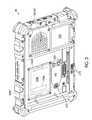
- FIG. 1is a front perspective view of a computer according to an embodiment of the invention
- FIG. 2is rear perspective view of the computer of FIG. 1 ;
- FIG. 3is rear perspective view of the computer of FIG. 1 with its battery removed;
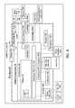
- FIG. 4is a block diagram of the computer of FIG. 1 ;
- FIG. 5is a partial rear view of the computer of FIG. 1 , with an electronics cartridge removed to show several electronics interfaces of the computer;
- FIG. 6is a partial rear perspective of a motherboard of the computer with a radio connected to an interface of the computer;
- FIG. 7is a front view of an interface converter that may be used in conjunction with the computer of FIG. 1 ;
- FIG. 8is a rear view of the interface converter of FIG. 7 ;
- FIG. 9is a partial rear view of the computer of FIG. 1 , with the converter of FIG. 7 mounted to an interface of the computer;
- FIG. 10is a partial rear view of the computer of FIG. 1 , with the converter of FIG. 7 mounted to the computer and a radio mounted to the converter;
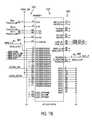
- FIGS. 11A-11Eare wiring/pin layout diagrams for the interface converter of FIG. 7 ;
- FIG. 12is a partial rear view of the computer of FIG. 1 showing an electronics interface door in an open position
- FIG. 13is a partial cross-sectional view of the computer of FIG. 1 showing the electronics interface door in a closed position;
- FIG. 14is a rear perspective view of the computer of FIG. 1 showing an electronics cartridge in a partially disengaged position relative to an electronics cartridge bay of the computer;
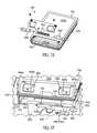
- FIG. 15is a lower perspective view of the electronics cartridge of FIG. 14 ;
- FIG. 16is a partially-exploded, upper perspective view of the electronics cartridge of FIG. 14 ;
- FIG. 17is a partial perspective view of the computer of FIG. 1 showing the electronics cartridge in a partially removed position;
- FIGS. 18 and 19are partial, cross-sectional views of the computer of FIG. 1 showing the electronics cartridge in an engaged position;
- FIG. 20is a perspective, exploded view of the cartridge of FIG. 14 containing a plurality of hard drives;
- FIG. 21is a perspective, exploded view of an alternative embodiment of an electronics cartridge for use with the computer of FIG. 1 , wherein the cartridge includes a mass storage device and a video processor;
- FIG. 22is a partial front view of a motherboard and remote heat exchanger of the computer of FIG. 1 ;
- FIG. 23is a partial, perspective, exploded view of a connection between an electronics interface of the cartridge bay and the case of the computer;
- FIGS. 24 and 25are partial cross-sectional views of the computer of FIG. 1 , showing the electronics cartridge bay, an electronics interface thereof, and the electronics cartridge;
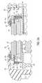
- FIG. 26is a partial cross-sectional view of the computer of FIG. 1 , taken along the line 26 - 26 in FIG. 1 ;
- FIG. 27is a partial cross-sectional view of the computer of FIG. 1 , taken along the line 27 - 27 in FIG. 1 ;
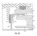
- FIG. 28is a detailed view of the cross-sectional view in FIG. 26 ;
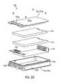
- FIG. 29is a perspective exploded view of the display and supporting frame of the computer of FIG. 1 .
- FIGS. 1-22illustrate a tablet PC 10 according to an embodiment of the invention.
- the illustrated computer 10comprises a tablet PC
- a variety of different types of computersmay alternatively be used according to various embodiments of the present invention (e.g., a portable laptop PC with a display that pivots (or otherwise moves) open and closed relative to the PC's case; a desktop PC with a case that is physically separate from the display; a handheld computer such as a smartphone, PDA, etc.).
- the tablet 10comprises, among other things, a case 20 , a motherboard 40 , a chipset 50 , a display 80 , a remote heat exchanger 100 , a plurality of electronics interfaces 200 , 210 , 220 , 400 , a docking connector 250 , a battery 550 , an electronics access door 410 , a GPS 590 .
- one or more radios 380 , 620that utilize antennas 630 , 640 , a cartridge bay 800 that accepts a variety of modular, modular electronics-containing cartridges 700 , 1000 , and power and function switches 1200 , 1210 .
- the case 20provides a structural frame for the tablet 20 .
- the case 20is defined by a plurality of separate components that connect to each other.
- the case 20may alternatively be defined by greater or fewer structures without deviating from the scope of the present invention.
- the case 20may comprise materials that are light, strong, impact resistant, abrasion-resistant, scratch-resistant, shock-absorbing, and/or water-tight (e.g., aluminum, titanium, magnesium, plastic, rubber, elastomeric materials, etc.).
- the main upper and lower structural portions of the case 20 and the door 410comprise magnesium, while a holed cover 180 for the fan 140 comprises plastic.
- the case 20either alone or in combination with other components (e.g., the display 80 , the door 410 , cartridge 700 , 1000 ), creates a water-tight, sealed compartment 30 (also known as a “dry” compartment).
- the sealed compartment 30contains a variety of the tablet components, including, among others, the motherboard 40 , chipset 50 , interfaces 200 , 210 , 220 , 400 , 770 , electric contacts 350 , 480 , 490 , an interface converter 300 , radio(s) 380 , 620 , SIM and memory cards 440 , 460 , a speaker 230 , and a microphone 240 .
- the case 20likewise defines a “wet” space 60 that is disposed outside of the “dry” compartment 30 and is exposed to the ambient environment outside of the sealed compartment 30 .
- the wet space 60includes space within the case 20 , but outside of the sealed compartment 30 , and space outside of the case 20 .
- Tablet 10 componentssuch as a fan 140 , heat sink 130 , docking interface 250 , power connector 560 , battery 550 , GPS 590 , switches/buttons 1200 , 1210 , and antennas 630 , 640 are disposed at least partially in the wet space 60 .
- Some components of the tablet 10are partially disposed in the sealed compartment 30 and partially disposed in the wet area 60 , including, for example, the display 80 , the heat pipe 110 , the power connector 560 , and the door 410 .
- a suitable sealing structuree.g., a gasket, silicone sealant
- a gasket, silicone sealantis used to seal the portion of the component in the sealed compartment 30 from the portion of the component in the wet space 60 .
- any one or more components of the tablet 10may be disposed in a different space 30 , 60 , depending on the environment in which the tablet 10 is to be used, the ruggedness of the component, and/or other design consideration(s) without deviating from the scope of the present invention.
- the speaker 230 and microphone 240may be disposed in the wet space 60 .
- the phrase “water-tight” in reference to a connection or sealmeans that the connection will prevent water leakage therethrough when the connection is submerged in water.
- the entire sealed compartment 30(including all water-tight connections/seals that separate the compartment 30 from the wet space 60 ) is water-tight to a water depth of at least 1 meter.
- the motherboard 40is supported by the case 20 .
- the motherboard 40comprises a printed circuit board (PCB), a plurality of PCBs, or another structure suitable for use in electrically interconnecting circuits, chips 50 , 70 , interfaces 200 , 210 , 220 , 770 , the display 80 , components, cards 440 , 460 , devices 380 , 620 , a battery 550 , the cartridge(s) 700 , 1000 , etc. to each other.
- PCBprinted circuit board
- various components of the tablet 10may alternatively directly connect to each other without the use of an intermediary motherboard 40 , according to various embodiments of the present invention.
- the chipset 50electrically connects to the motherboard 40 .
- the chipset 50comprises one or more chips for providing functionality to the tablet 10 (e.g., for communicating with electronics components of the tablet, for running an operating system of the tablet 10 (e.g., Microsoft Windows, Linux, etc.), for running executable programs/code stored on a storage device of the tablet 10 , for running the display 80 and screen 81 thereof, for running the user interface (e.g., the touch panel 82 ) of the tablet 10 , for interconnecting tablet components).
- the chipset 50includes a variety of chips and circuits, including, among others, a central processing unit (CPU) 70 (see FIG. 22 ), a platform controller hub (PCH) 75 (see FIG.
- the chipset 50may additionally and/or alternatively comprise other chips/circuits without deviating from the scope of the present invention.
- the processor 70may comprise any suitable processor (e.g., Intel® CoreTM i7 processor, other Intel® CoreTM i processors, Intel dual core processors, Intel Atom processors, AMD processors, ARM based processors, etc.) or combination of processors (e.g., a dual processor, quad processor, etc.) for carrying out various functions of the tablet 10 (e.g., running the operating system and programs/executable code).
- the processor 70generates at least 8, 9, 10, 11, 12, 13, 14, or 15 watts of heat during use.
- the display 80is supported by the case 20 and electrically connected to the chipset 50 (e.g., a GPU or CPU of the chipset) via the motherboard 40 .
- the display 80includes a screen 81 and a touch panel 82 disposed outwardly from the screen 81 .
- the display 80(and particularly the screen 81 thereof) faces toward the touch panel 82 and outward away from the case 20 through a display opening 83 in the case 20 .
- a rear side 80 a of the display 80including the screen 81 , is disposed in the sealed compartment 30 .
- the touch panel 82is accessible through the display opening 83 in the case 20 and the screen 81 is viewable through the opening 83 and transparent portion of the touch panel 82 .
- an elastomeric gasket 84surrounds a perimeter of the opening 83 and is glued or otherwise adhered in a water-tight manner to the case 20 .
- the gasket 84 and touch-panel 82press against each other to form a water-tight seal that separates the sealed compartment 30 on the interior side of the touch panel 82 from the wet space 60 on an exterior side of the touch panel 82 .
- the sealing force exerted between the touch panel 82 and gasket 84is created by the case 20 , a chassis 85 , and a frame 86 .
- the chassis 85mounts to the case 20 , or is formed by the case 20 .
- the frame 86rests on top of the chassis 85 .
- the frame 86follows the perimeter of the opening 83 and the perimeter of the touch panel 82 .
- a perimeter of the touch panel 82rests on top of and is supported by the frame 86 .
- the touch panel 82may be glued or otherwise fastened to the frame 86 (e.g., via double-sided pressure sensitive adhesive tape). Alternatively, the touch panel 82 may be held in place solely by it being sandwiched between the gasket 84 and frame 86 .
- the compressive force that provides the water-tight seal between the touch panel 82 and gasket 84is transferred from the case 20 to the chassis 85 , from the chassis 85 to the frame 86 , from the frame 86 to the touch panel 82 , and finally from the touch panel 82 back to the gasket 84 that is supported by the case 20 .
- the compressive forceis developed when the case 20 is bolted (or otherwise fastened) together while the chassis 85 , frame 86 , touch panel 82 , and gasket 84 are in place.
- the tightening of the boltscreates the compressive force as the chassis 85 (and lower portion of the case 20 ) is pressed toward the upper portion of the case 20 .
- the direct transfer of sealing force from structural components of the tablet 10e.g., the case 10 , chassis 85 , and frame 86
- the touch panel 82 and gasket 84facilitates an accurate and precise application of constant sealing force around the entire perimeter of the seal between the gasket 84 and touch panel 82 .
- the use of the frame 86provides for a precise stackup distance between the upper surface of the chassis 85 and the upper surface of the touch panel, which contacts the gasket 84 .
- the stackup distanceis 9.28 mm, but may be other distances according to other embodiments of the present invention.
- the sealing force that seals the gasket 84 and touch panel 82 togetheris not transferred through the display screen 81 .
- the screen 81is isolated from the sealing force exerted between the touch panel 82 and gasket 84 .
- avoiding such force transfer through the screen 81may provide several benefits.
- compression of the screen 81 that would result from transferring the sealing force through the screen 81may lead to damage of the screen 81 and light bleed through the compressed pixels of the screen 81 , particularly in embodiments where relatively high sealing forces are used to improve the water-tight seal (e.g., increase a water depth to which the seal is water-tight).
- the gasket 84could be glued to both the case 20 and the touch panel 82 to ensure a water-tight seal even in the absence of compressive sealing force.
- the gasket 84is glued to the case 20 and compressed against the touch panel 82 .
- the gasket 84could be glued to the touch panel 82 and compressed against the case 20 without deviating from the scope of the present invention.
- the connections between the gasket 84 and both the case 20 and touch panel 82could rely on a compression seal, rather than glue or another intermediary adhesive.
- the chassis 85comprises magnesium
- the frame 86comprises stamped, bent, 0.3 mm stainless steel.
- the chassis 85 and frame 86may alternatively comprise other materials without deviating from the scope of the present invention.
- the frame 86 and chassis 85are integrally formed (e.g., via common casting or subsequent permanent bond).
- an upper side of a structural frame 81 a of the screen 81is mounted to the frame 86 via double-sided, pressure sensitive adhesive tape 87 (or another suitable fastener).
- the frame 86has an “L” shaped cross-sectional shape.
- the structural connection between the chassis 85 and frame 86is on an opposite leg of the “L” from the structural connection between the frame 86 and touch panel 82 .
- the structural connection between the chassis 85 and frame 86is on an opposite leg of the “L” from the structural connection between the frame 86 and the screen 81 .
- the frame 86comprises a material with some elastic properties (e.g., stainless steel), such that the “L” shape can flex to some degree to permit limited movement of the opposite legs of the frame 86 relative to each other.
- the frame 86Such elastic deformation enables the frame 86 to protect the touch panel 82 and screen 82 from vertical shocks and vibrations that might otherwise be transferred from the chassis 85 to the touch panel 82 and screen 81 via the frame 86 .
- the elasticity of the “L” shapealso facilitates a more consistent sealing pressure around the perimeter of the touch panel 82 .
- a lower side of the screen 81is supported by the chassis 85 via intermediary strips of silicon rubber 88 that protect the screen 81 from vertical shocks and vibrations imparted on the case 20 (e.g., if the tablet 10 was dropped on its rear face opposite the display 80 ).
- strips of silicon foam 89are disposed between the sides of the frame 86 and the chassis 85 or case 20 .
- the strips 89protects the frame 86 and screen 81 and touch panel 82 mounted thereto from lateral/side shocks and vibrations imparted on the case 20 .
- the strips 88 , 89may be held in place via any suitable fastener (e.g., glue, tape, incorporation of the strips 88 , 89 into single-sided or double-sided foam/rubber tape).
- suitable fastenere.g., glue, tape, incorporation of the strips 88 , 89 into single-sided or double-sided foam/rubber tape.
- the strips 88comprise silicon rubber and the strips 89 comprise silicon foam.
- the strips 88 , 89may alternatively comprise any other suitable material (e.g., an elastomer, an elastic material, foam, rubber, etc.) without deviating from the scope of the present invention.
- the frame 86laterally surrounds the screen 81 .
- Mylar frame spacers 91are fastened to the inner lateral corners of the frame 86 .
- the spacer 91are disposed laterally adjacent to the frame 81 a of the screen 81 to ensure proper lateral positioning of the screen 81 relative to the touch panel 82 and case 20 .
- the touch panel 82can be replaced by a transparent sheet of material such as a sheet of glass or plastic, or omitted altogether.
- an electronics devicecomprising:
- a display screendisposed in the sealed compartment and viewable through the opening
- a touch paneldisposed outwardly of the screen
- a gasketdisposed between the touch panel and the case, the gasket and touch panel sealing the opening to separate the sealed compartment from an environment surrounding the electronics device,
- the electronics devicecreates a sealing force that urges the touch panel toward the opening relative to the case and against the gasket to seal the opening via the gasket
- the display screenis isolated from the sealing force.
- the electronics devicecomprises a computer, and the computer includes a chipset disposed in the sealed compartment, the chipset being electrically connected to the display screen and touch panel.
- the electronics devicecomprises a frame through which the sealing force is transferred, wherein the screen and touch panel are both supported by the frame.
- the screen 81comprises a high intensity/brightness screen 81 (see FIG. 1 ) that facilitates improved viewability of the screen 81 in bright environments (e.g., outdoors in direct sunlight).
- the screen 81may be an LED, CCFL, or OLED display (e.g., a high intensity, advanced fringe field switching (AFFS) screen module from Hydis Technologies Co.).
- AFFSadvanced fringe field switching
- One or more embodiments of the screen 81provide a brightness of at least 500 NIT (a luminance unit equal to 1 candle per square meter measured perpendicular to the rays from the source), at least 600 NIT, at least 700 NIT, and/or somewhere between 500 and 1000 NIT across its viewable area.
- the screen 81 of the display 80is at least a 6, 7, 8, 9, 10, 11, 12, and/or 13 inch screen, measured diagonally.
- a viewable area of the screen 81is at least 15, 20, 25, 30, 35, 40, 45, 50, 60, 70, 80, 90, and/or 100 square inches.
- the screen 81is a 10.4 inch diagonal screen having a 4:3 aspect ratio and a viewable area of about 52 square inches.
- the screen 81releases at least 1, 2, 3, 4, 5, 6, 7, 8, 9, and/or 10 or more watts of heat into the sealed compartment 30 when operated in high brightness/intensity mode.
- the screen 81comprises a heat sink 90 (see FIGS. 4 and 29 ) disposed on a rear side of the screen 81 in the sealed compartment 30 to dissipate heat from the high-intensity screen 81 into the sealed compartment 30 .
- the heat sink 90may span a large portion of an area of the screen 81 and comprise a high-heat conductivity material such as aluminum.
- the touch panel 82provides a user-interface for the tablet 10 .
- the touch panel 82is a multi-mode touch panel 82 that provides for user (or tablet 10 ) selection between the following modes: a touch only operating mode, a stylus only operating mode, and a dual mode with the stylus operation taking priority over touch operation.
- the high-intensity screen 81 and high-power chipset 50(and specifically the processor 70 and PCH 75 thereof) dissipate a large amount of heat into the sealed compartment 30 . Because the compartment 30 is sealed according to one or more embodiments, the compartment 30 according to one or more embodiments does not dissipate heat into the ambient environment as well as various unsealed compartments would. Moreover, according to one or more embodiments, the display 80 , chipset 50 , and other components in the sealed compartment 30 generate so much heat that a passive heat exchanger incorporated into the case 20 (e.g., a metal heat sink that thermally connects the sealed compartment 30 to the wet space 60 ) would get so hot that it would be uncomfortable for some users to touch.
- a passive heat exchanger incorporated into the case 20e.g., a metal heat sink that thermally connects the sealed compartment 30 to the wet space 60
- the active coolant remote heat exchanger (RHE) 100dissipates such heat and facilitates the use of a high-intensity display 80 (e.g., 500+ NIT) and/or the combined use of a high intensity display 80 (500+ NIT) and a high power CPU 70 that generates 5, 6, 7, 8, 9, and/or 10 watts or more of heat.
- a high-intensity display 80e.g., 500+ NIT
- a high intensity display 80e.g., 500+ NIT
- CPU 70e.g., a high power CPU 70 that generates 5, 6, 7, 8, 9, and/or 10 watts or more of heat.
- the RHE 100is supported by the case 20 and is constructed and positioned to draw heat from within the sealed compartment 30 and dissipate the heat into the ambient environment/wet space 60 around the tablet 10 .
- the RHE 100includes a coolant passage 110 , a coolant 120 , a heat sink 130 , and a fan 140 .
- the coolant passage 110(also known as a heat pipe) contains the coolant 120 , whose flow is configured to carry heat out of the sealed compartment 30 and into an ambient air/wet space 60 outside of the sealed compartment 30 .
- the coolant passage 110has a first portion 110 a that is thermally exposed to the sealed compartment 30 , and a second portion 110 b disposed outside of the sealed compartment 30 . Heat-induced evaporation of the coolant in the first portion 110 a and cooling-induced condensation of the coolant 120 in the second portion 110 b cause the coolant 120 to flow between the first and second portions 110 a , 110 b , thereby carrying heat out of the sealed compartment 30 .
- the first portion 110 a of the coolant passage 110is thermally coupled to the processor 70 (e.g., via direct contact, through mutual contact with an intermediary heat transfer medium, via mutual contact with an intermediary heat sink 150 (see FIG. 22 ), etc.) so as to pull heat directly from the heat-producing processor 70 .
- the heat sink 150is spring-loaded to as to press against the processor 70 , thereby keeping the processor 70 in place.
- the heat sink 150is thermally coupled to first portion 110 a so as to thermally couple the first portion 110 a to the processor 70 .
- the first portion 110 amay be thermally coupled to other heat producing components of the tablet 10 so as to better dissipate heat generated within the sealed compartment 30 .
- the first portion 110 ais thermally coupled to the heat sink 90 of the display 80 .
- the first portion 110 ais also thermally coupled to the PCH 75 via an intermediate heat sink 160 .
- the first portion 110 aalso extends within the sealed compartment 30 so as to generally pull heat from the space within the sealed compartment 30 .
- the heat sinks 150 , 160also serve as general heat sinks for the first portion 110 a to help the first portion 110 a absorb heat from within the sealed compartment 30 .
- the sealed compartment 30is fan-less, and the RHE 100 relies on natural circulation of gas within the sealed compartment 30 and/or heat transfer through the gas in the sealed compartment 30 to transfer heat from various components in the sealed compartment 30 to the first portion 110 a.
- the heat sink 130is supported by the case 20 , disposed in the wet space 60 , and thermally coupled to the second portion 110 b .
- the heat sink 130comprises a plurality of heat-dissipating fins.
- thermal couplingmeans a coupling that facilitates more heat transfer between components than would be provided if the components were separated by an air gap.
- Thermal couplingmay comprise direct contact between components.
- Thermal couplingmay comprise the use of an intermediary structure between the components, wherein the intermediary structure is designed to improve heat transfer between the components (e.g., a high thermal conductivity metal in mutual contact with both components, a high thermal conductivity paste in mutual contact with the components, etc.).
- the term “remote” in “remote heat exchanger”means that a portion of the heat exchanger is disposed remote from another portion of heat exchanger (e.g., one portion being disposed in a position to absorb heat, and a “remote” portion being disposed in a position to expel heat).
- the portion 110 a of the RHE 100is disposed in the sealed compartment 30 , and is therefore remote from the portions 110 b (and fan 140 and heat sink 130 ), which is disposed in the wet space 60 .
- the portions 110 a , 110 bare “remote” from each other despite both being part of the tablet 10 .
- the fan 140is supported by the case 20 and disposed outside of the sealed compartment 30 in the wet space 60 .
- the fan 140is powered by the battery 550 .
- the fan 140is positioned to direct a flow of ambient air over the heat sink 130 so as to facilitate heat transfer from the heat sink 130 to the ambient air.
- the fan 140is connected to the motherboard 40 and controlled by the chipset 50 .
- the chipset 50may turn the fan 140 on when a temperature in the sealed compartment 30 exceeds a threshold and turn the fan 140 off when the temperature is below a threshold.
- the holed fan cover 180covers the fan 140 and allows fan-induced ambient air flow through the cover 180 .
- the fan cover 180comprises plastic to minimize heat transfer to the user through via the cover 180 .
- the RHE 100may be eliminated altogether or replaced with a passive heat exchanger such as a passive heat sink, for example if the heat output within the sealed compartment 30 is below a certain threshold.
- a plurality of electronics interfaces 200are provided on or otherwise electrically connected to the motherboard 40 and chipset 50 to facilitate electric connections between and among the peripheral electronics devices, tablet 10 components, and the chipset 50 , among others.
- Such electronics interfaces 200may include, among others, PCI-X slots, mini-PCI Express slots 210 , 220 (see FIG. 5 ), USB interfaces, a speaker port 230 (e.g., a 3.5 mm jack) or built in speaker, a microphone port 240 (e.g., a 3.5 mm jack) or built in microphone, docking port interfaces 250 , an electronics interface 400 , a SIM card interface 430 , a memory card interface 450 , etc.
- the mini-PCI Express slot/interface 210facilitates connection to the motherboard 40 and chipset 50 of a peripheral electronics device such as a mini-PCI Express card 620 (e.g., a wireless wide area network (WWAN) data packet radio card 620 ) via the mini-PCI Express interface specification.
- a peripheral electronics devicesuch as a mini-PCI Express card 620 (e.g., a wireless wide area network (WWAN) data packet radio card 620 ) via the mini-PCI Express interface specification.
- the chipset 50supports the mini-PCI Express interface specification (e.g., via a suitable PCI controller).
- any other suitable interface specificationmay be used without deviating from the scope of the present invention.
- the mini-PCI Express interface specificationdoes not support various signals.
- the specificationdoes not support voice communications (e.g., analog speaker and microphone signals).
- a removable interface converter 300is used.
- the converter 300converts the mini-PCI Express interface 210 into a specialized, voice-capable mini-PCI Express interface 340 without the need to add a stand alone, specialized voice-capable interface to the tablet 10 .
- the converter 300therefore provides increased functionality to the tablet 10 , without taking up significant additional space in the tablet 10 .
- the converter 300comprises a substrate 310 (e.g., a PCB), a mini-PCI Express connector 320 , a plurality of pogo pins 330 , and a specialized mini-PCI Express interface/slot 340 .
- a substrate 310e.g., a PCB
- mini-PCI Express connector 320e.g., a PCB
- pogo pins 330e.g., a plurality of pogo pins 330
- a specialized mini-PCI Express interface/slot 340e.g., a specialized mini-PCI Express interface/slot 340 .
- the mini-PCI Express connector 320is supported by the substrate 310 and includes a plurality of edge finger electric contacts 320 a .
- the connector 320 of the converter 300is removably physically and electrically engageable with the mini-PCI Express interface 210 .
- the connection between the connector 320 and interface 210 via the electric contacts 320 aprovides for communication according to the mini-PCI Express interface specification.
- any other suitable interface specification and interface typemay be used without deviating from the scope of the present invention (e.g., mini-PCIexpress, USB, PCMCIA, SATA, I ⁇ 2 C, or any other suitable electronics bus).
- This mini-PCI Express connectionprovides power, USB, mini-PCIexpress, I ⁇ 2 C, and SIM signals to the converter 300 according to the mini-PCI Express interface specification.
- the mini-PCI Express interface specificationdoes not provide for analog voice signals.
- the converter 300is provided with voice signals (or other types of communication signals not provided via the mini-PCI Express interface specification) via the pogo pins 330 (see FIG. 8 ) and a plurality of corresponding electric contacts 350 (see FIG. 5 ) on the motherboard 40 .
- the plurality of pogo pins 330are supported by the substrate 310 .
- the pogo pins 330are spring-biased electric contacts.
- the plurality of corresponding electric contacts 350are supported by the motherboard 40 and electrically connected to the chipset 50 , which may connect the contacts 350 to suitable devices such as the microphone 240 (or microphone port such as a 3.5 mm jack accessible from outside of the tablet 10 ) and speaker 230 (or speaker port such as a 3.5 mm jack accessible from outside of the tablet 10 ).
- suitable devicessuch as the microphone 240 (or microphone port such as a 3.5 mm jack accessible from outside of the tablet 10 ) and speaker 230 (or speaker port such as a 3.5 mm jack accessible from outside of the tablet 10 ).
- the converter 300is removably connectable to the interface/slot 210 and the electric contacts 350 .
- connection between the contacts 330 and contacts 350utilize pogo pins 330 on the substrate 310 and contact pads 350 on the motherboard 40 , respectively, any other suitable electric contacts/connections may be used without deviating from the scope of the present invention.
- the contacts 320 aare physically separated or spaced from the contacts 330 .
- the connector 320 and its contacts 320 aare disposed at an end of the substrate 310 .
- the contacts 330are disposed at a central portion of the substrate 310 that is spaced from the end, and spaced from all of the peripheral edges of the substrate 310 .
- the specialized mini-PCI Express interface/slot 340is supported by the substrate 310 and comprises a plurality of electric contacts 360 . Some of the electric contacts 360 are connected/routed to some of the electric contacts 320 a , respectively. Others of the electric contacts 360 are connected/routed to the electric contacts 330 , respectively.
- FIGS. 11A-11Eprovide the pin callouts/connections for the contacts 330 , contacts 320 a , and contacts 360 of the converter 300 according to an embodiment of the invention.
- the combination of electric contacts 320 a , 330 that are routed to the interface 340 and its contacts 360define pin callouts for an interface specification that differs from the specification of the interface 210 (e.g., by providing/supporting analog voice (e.g., speaker/microphone) capabilities that are not provided by the interface specification of the interface 210 ).
- the illustrated converter 300provides a voice-capable interface according to a voice-capable interface specification
- the converter 300 and contacts 330 , 350may alternatively provide any other useful signal functionality to support any other suitable interface specifications without deviating from the scope of the present invention.
- the interface 340is configured to engage an interface connector 370 of a peripheral electronics device 380 via the plurality of electric contacts 360 according to the voice-capable interface specification.
- the device 380is a voice-capable radio 380 .
- the chipset 50is configured to receive analog speaker signals from the interface 340 and device 380 via at least one of the electric contacts 330 , 350 .
- the chipset 50is configured to send analog microphone signals to the interface 340 and device 380 via at least one of the first electric contacts 330 , 350 .
- the converter 300facilitates electrical connection of the device 380 to the tablet 10 (and chipset 50 ) via a combination of the interface 210 and the contacts 350 , 330 according to a voice-capable interface specification.
- the interface 340 and connector 370have the form factor and pin positions of a conventional mini-PCI Express interface/card, but utilize the non-standard pin callouts for the voice-capable interface specification (sometimes referred to as a specialized mini-PCI Express interface). According to alternative embodiments of the present invention, the interface 340 and connector 370 may use any other suitable form factor, pin positions, and/or connection type without deviating from the scope of the present invention.
- an electronics interface 400mounts to a door 410 and electrically connects to the chipset 50 via an electrical connector 480 .
- the electronics interface 400is configured to removably engage at least one electronics device (e.g., SIM card 440 , microSD card 460 ).
- the electronics interface 400comprises a substrate 420 (e.g., one or more PCBs), a SIM card interface/slot 430 for a SIM card 440 , and a memory card interface/slot 450 for a memory card 460 (e.g., flash memory, SD, SDHC, microSD, microSDHC).
- a substrate 420e.g., one or more PCBs
- SIM card interface/slot 430for a SIM card 440
- a memory card interface/slot 450for a memory card 460
- flash memorySecure Digital, Secure Digital High Capacity
- SDHCSecure Digital High Capacity
- microSDmicroSDHC
- the door 410mounts to the case 20 for pivotal movement relative to the case 20 between an open position (shown in FIG. 12 ) and a closed position (shown in FIGS. 3 , 13 ).
- provision of the interface 400 on the door 410provides easier access to, removal of, and insertion of the SIM card 440 and memory card 460 than is provided according to various conventional computers in which a SIM/memory interface is disposed in a deep recess in the case of a computer.
- the electrical connector 480comprises a plurality of electric contacts in the form of pogo pins that are mounted to and project from the substrate 420 .
- the pogo pins 480are electrically connected to the interfaces 430 , 450 so as to electrically connect to the cards 440 , 460 when the cards 440 , 460 are connected to the interfaces 430 , 350 .
- a plurality of corresponding electric contacts 490are supported by the motherboard 40 and electrically connected to the chipset 50 .
- the pins/contacts 480electrically contact respective ones of the contacts 490 when the door 410 is in the closed position, but do not electrically contact the respective ones of the contacts 490 when the door 410 is in the open position.
- the pins/contacts 480electrically connect the cards 440 , 460 (or other electronics devices connected to the interface 400 ) to the chipset 50 via the electronics interface 400 when the door 410 is in the closed position and the card 440 and/or card 460 engages the electronics interface 400 .
- the pins/contacts 480do not electrically connect the card 440 and/or card 460 to the chipset 50 via the electronics interface 400 when the door 410 is in the open position and the card 440 and/or card 460 engage(s) the electronics interface 400 .
- the case 20comprises a hole 500 through which the pins 480 move when the door 410 moves from its open position to its closed position.
- the hole 500is preferably small (e.g., smaller in length or area than one or more of the interface 400 , the card 440 , and/or the card 460 ) so as to reduce an amount of electromagnetic and/or radio frequency interference that can enter the compartment 30 via the hole 500 .
- the electrical connection between the interface 400 and the motherboard 40comprises pogo pins 480 on the door 410 and contact pads 490 on the motherboard 40 .
- the relative positions of the pins and padsmay be reversed without deviating from the scope of the present invention.
- the pinsmay continuously extend from the motherboard 40 through the hole 500 .
- the pins 480 and pads 490may alternatively be replaced by any other suitable connection that is formed by the closing of the door 410 without deviating from the scope of the present invention (e.g., male and female multi-pin connectors, a connector/interface similar or identical to the interface 770 and connector 760 used by the below discussed cartridge 700 ).
- contacts 480 , 490that electrically connect to each other when the door 410 closes may simplify construction of the tablet 10 according to one or more embodiments of the invention because the pads/contacts 490 can be formed on the motherboard 40 before the motherboard is mounted to the case 20 . Similarly, the pins/contacts 480 can be mounted to the interface 400 before the interface 400 is mounted to the case 20 . Once the motherboard 40 and interface 400 are mounted to the case 20 , no further electrical connections or soldering need be made to facilitate connection between the motherboard 40 and the interface 400 , despite them being on opposite sides of a small hole 500 in the case 20 .
- the interface 400permanently electrically connects to the motherboard 40 via one or more cables that are soldered to or otherwise connected to the motherboard 40 and interface 400 during manufacture of the tablet 10 .
- Such a cable or cablescould extend through the hole, and the hole could be sealed around the cable to discourage debris from entering the sealed compartment 30 .
- a tool-less locking mechanism 510selectively locks the door 410 in the closed position.
- the locking mechanism 510is manually movable by a user's hand between a locking position that locks the door 410 closed, and a released position that permits the door 410 to be opened and closed.
- the locking mechanism 510comprises a manually-operable, partial-turn, D-ring latch.
- any other suitable locking mechanismmay alternatively be used without deviating from the scope of the present invention (e.g., tool-less or tool-requiring mechanism, captive bolt/screw, a latch or latches such as the latches 880 , 890 discussed below, etc.).
- a piston seal 530surrounds the hole 500 and seals the hole 500 from the ambient environment/wet space 60 outside of the sealed compartment 30 or computer 10 when the door 410 is in the closed position.
- the seal 530is mounted to and moves with the door 410 relative to the case 20 such that the seal 530 is sandwiched between a side wall 540 a of a recess 540 in the case 20 and the door 410 when the door 410 is closed.
- the piston seal 530functions in a manner that is similar to or identical to the piston seal 790 of the below-discussed cartridge 700 .
- the interface 400 and cards 440 , 460are therefore disposed within the sealed compartment 30 of the tablet 10 when the door 410 is closed.
- the locking mechanism 510may be designed to press the door 410 against the case 20 to compress the seal 530 and improve its sealing properties (e.g., improving its water-resistance and debris-resistance).
- an arm of the D-ring pin of the mechanism 510may ride over a ramp/cam built into the case 20 as the pin is rotated toward its locked position so as to further press the door 410 against the case 20 and compress the seal 530 .
- the battery 550 of the tablet 10is described with reference to FIGS. 2 , 3 , and 4 .
- the battery 550is movable between an attached position (shown in FIG. 2 ) and a detached position (shown in FIG. 3 ).
- the battery 550In the attached position, the battery 550 is supported by the case 20 and electrically connects to the motherboard 40 (and other components such as the chipset 50 and display 80 ) via a power connector 560 (see FIGS. 3 , 4 ) to provide power to the tablet 10 .
- the battery 550In the detached position, the battery 550 is not electrically connected to the tablet 10 , and may or may not be physically connected to the tablet 10 .
- a manually releasable locking mechanism 570selectively retains the battery 550 in the attached position.
- the battery 550may comprise one or more battery cells (e.g., a 4, 6, 8, 10 cell battery 550 ).
- the battery 550when the battery 550 is in its attached position, the battery 550 covers the door 410 and discourages or prevents the door 410 from being moved from its closed position to its open position. This, in turn, prevents the cards 440 , 460 from being removed from the interface 400 unless the battery 550 is removed. This arrangement may reduce the chance of memory damage/loss to the memory card 460 , which might otherwise occur if the card 460 were removed while still being powered by the battery 550 .
- GPS module 590 of the tablet 10is described with reference to FIGS. 1 and 4 .
- the GPS module 590 modulefixedly mounts to an exterior of the case 20 and electrically connects to the motherboard 40 and chipset 50 to provide GPS functionality to the tablet 10 .
- the type of GPS module 590 used in combination with its positioning on the exterior of the case 20provides sub-meter GPS accuracy (i.e., 100% of data is within 1.0 meters of accurate) according to one or more embodiments of the invention. Such accuracy may result from a combination of one or more of the following: the module's inclusion of a dedicated GPS antenna, the positioning of the module 590 on the top of the case 20 so as to provide an unobstructed view to the sky/GPS satellites, and/or the use of the latest generation GPS engine (e.g., from U-blox or others).
- the GPS module 590comprises a GPS 2 Pro module.
- antennas 630 , 640tuned to different geographical regions is described with reference to FIGS. 1 , 4 , 6 , and 10 .
- the tablet 10includes a radio such as the data packet radio 620 shown in FIG. 6 and/or the voice radio 380 shown in FIG. 10 .
- the radios 380 , 620connect to the motherboard 40 via suitable interfaces 210 , 340 .
- the radios 380 , 620include a main antenna connection 380 a , 620 a and an auxiliary antenna connection 380 b , 620 b .
- the main antenna connection 380 a , 620 ais used for transmitting signals and receiving signals.
- the auxiliary connection 380 b , 620 bis used for receiving signals and may be used for diversity.
- the tablet 10includes two antennas 630 , 640 mounted to the case 20 .
- Different cellular/mobile radio frequenciesare used in different geographical regions (e.g., U.S. and Europe).
- the U.S.-tuned antenna 630is tuned to have a small loss (e.g., 3 dB or less in the transmit/receive) in the frequency range used in a first region (e.g., the U.S.), while having a larger loss (e.g., 5 dB loss) in the frequency range used in a second region (e.g., Europe).
- the Europe-tuned antenna 640is tuned to have a small loss (e.g., 3 dB or less in the transmit/receive) in the frequency range used in the second region, while having a larger loss (e.g., 5 dB loss) in the frequency range used in the first region.
- a small losse.g., 3 dB or less in the transmit/receive
- a larger losse.g., 5 dB loss
- the antenna 630 , 640 that is tuned to the region for which the tablet 10 is intended to be usedis hard-wired to the main antenna connection 380 a , 620 a , while the other antenna 630 , 640 is hardwired to the auxiliary antenna connection 380 b , 620 b .
- Such hardwiringreduces signal loss relative to an alternative use of an intermediary switch that would switch relative connections of the antennas 630 , 640 and connections 380 a , 620 a / 380 b , 620 b .
- such a switchmay be used.
- both antennas 630 , 640are included in each tablet 10 manufactured, regardless of whether the tablet 10 is intended for use/delivery into the first or second region.
- the use of two antennas 630 , 640may be less expensive and/or take of less space than the use of a dual-band or multi-band antenna that is suitable for use across multiple regions.
- one or more embodiments of the present inventionprovide a method of manufacturing a plurality of computers, the method comprising: providing a computer with a radio and first and second antennas, the first antenna being tuned for use in a first geographical region, the second antenna being tuned for use in a second geographical region; determining which of the antennas is tuned for a geographical region of intended use of the computer; wiring the antenna that is tuned for the region of intended use to a main antenna connection of the radio; and wiring the antenna that is not tuned for the region of intended use to an auxiliary connection of the radio.
- the methodmay further comprise repeating these steps for additional computers with additional radios and antennas.
- the tablet's cartridge bay 800 and interchangeable cartridges 700 , 1000are described with reference to FIGS. 4 and 14 - 21 .
- the modular electronics cartridge 700is movable relative to a cartridge bay 800 of the computer 10 between an engaged position (shown in FIGS. 2 and 3 ) and a disengaged position (shown in FIG. 5 ).
- the cartridge 700is physically disconnected from the computer 10 (but may remain tethered or hinged to the computer 10 according to alternative embodiments of the invention).
- the cartridge 700comprises a cartridge shell 720 , electronics 730 disposed within the shell 720 , an interface connector 760 , a piston seal 790 , and latches 880 , 890 .
- the cartridge shell 720comprises first and second shell portions 720 a , 720 b that bolt together to define a cartridge compartment 720 c therein.
- the shell 720may alternatively be defined by greater or fewer structures without deviating from the scope of the present invention.
- the shell 720may comprise materials that are light, strong, impact resistant, abrasion-resistant, scratch-resistant, shock-absorbing, and/or water-tight (e.g., aluminum, titanium, magnesium, plastic, rubber, elastomeric materials, etc.).
- the cartridge shell 720has a top 720 d , a bottom 720 e , and a side 720 f extending in a loop between the top 702 d and bottom 720 e.
- the cartridge electronics 730are disposed in the cartridge compartment 720 c .
- the electronics 730comprise one or more mass storage devices (e.g., two 1.8 inch SATA hard disk and/or solid state drives 740 ) connected to suitable connector 750 (or controller).
- the electronics 730may alternatively comprise a variety of different types and combinations of electronics without deviating from the scope of the present invention.
- the electronicsmay comprise just one drive 740 .
- the electronicsmay alternatively comprise one or more mSATA drives or other mass storage devices connected to a suitable connector.
- the electronics 730may alternatively comprise a combination of mass storage and processors or other electronics devices (e.g., radios, processors, etc.).
- Multiple cartridges 700may be provided with different electronics 730 so as to provide increased functionality to the tablet 10 by replacing a cartridge 700 in the bay 800 with a different cartridge 700 .
- the interface connector 760electrically connects to the electronics 730 .
- the connector 760connects to the connector 750 , which, in turn, connects to the hard drives 740 .
- the connector 750could alternatively connect directly to the hard drives 740 without deviating from the scope of the present invention.
- the connector 760extends out of a hole 720 g in the shell 720 or is otherwise accessible through the hole 720 g.
- a corresponding electronics interface 770is disposed in the cartridge bay 800 and electrically connects to the chipset 50 (see FIG. 4 ).
- the interface connector 760 and interface 770create a SATA connection from the electronics 730 to the chipset 50 .
- the connectionprovides a data and power connection to the electronics 730 .
- any other suitable connection or interface typemay be used without deviating from the scope of the present invention.
- Engagement of the cartridge 700 with the bay 800causes the connector 760 to electrically engage the interface connector 770 so as to electrically connect the electronics 730 to the computer 10 and chipset 50 thereof.
- the piston seal 790mounts to the cartridge shell 720 and surrounds the interface connector 760 , specifically surrounding the hole 720 g in the shell 720 through which the connector 760 is accessible. As shown in FIGS. 15-21 , the piston seal 790 extends continuously around the side 720 f of the bay 800 and forms a continuous perimeter.
- the cartridge bay 800is supported by and/or at least partially defined by the case 20 of the tablet 10 .
- the bay 800comprises a removable bay bottom 810 and a bay side wall 820 extending outwardly from the bottom 810 .
- at least a portion 820 a of the bay side wall 820slopes away from an opposing portion 820 b (see FIG. 18 ) of the bay side wall 820 as the portion projects outwardly from the bottom 810 .
- the sloped portion 820 aextends around an entire perimeter of the side wall 820 . As shown in FIG.
- the sloped portion 820 aforms an angle ⁇ of less than 45, 30, 20, 15, 10, and/or 5 degrees relative to a direction of movement 780 of a part of the piston seal 790 that contacts the sloped portion 820 a as the cartridge 700 moves into its engaged position.
- the piston seal 790slides along the portion 820 a of the side wall 820 and is disposed in an increasingly interference fit with the portion 820 a and wall 820 generally, thereby creating a good seal between the perimeter of the cartridge 700 and the bay 800 when the cartridge is engaged in the bay 800 .
- the cartridge 700physically engages the cartridge bay 800 such that the piston seal 790 compressively engages the cartridge bay 800 and creates a water-tight seal that separates the interface connector 760 from an external environment (e.g., the wet space 60 ).
- a portion of the shell 720 on an opposite side of the seal 790 from the interface connector 760is preferably water-tight so as to form a door that in combination with the water tight seal created by the seal 790 separates the sealed compartment 30 from the wet space 60 .
- the side wall 820is preferably made of a strong, stiff material such as magnesium that is capable of enduring the force of the seal 790 , whose sealing force is amplified by the cam/ramp operation of the sloped portion 820 a.
- the seal 790facilitates the use of the engaged cartridge 700 as a door to the sealed compartment 30 .
- a usercan access components (e.g., the interfaces 210 , 220 and electronics devices 300 , 380 , 620 ) within the sealed compartment 30 of the tablet 10 via a resulting access hole 830 in the case.
- componentse.g., the interfaces 210 , 220 and electronics devices 300 , 380 , 620
- the access hole 830can be relatively large (e.g., at least 2, 3, 4, 5, 6, 7, 8, 9, 10, 11, 12, 13, and/or 14 square inches).
- the access hole 830provides external access (i.e. from outside of the tablet 10 and sealed compartment 30 ) to the interfaces 210 , 220 and any devices 300 , 380 , 620 connected thereto to facilitate easy insertion, removal, and/or replacement of such devices 300 , 380 , 620 , despite such devices being within the sealed compartment 30 .
- the cartridge bay 800 and the cartridge 700include complimentary surface features 850 (see FIG. 5 ), 860 (see FIG. 21 ) that form a rough hinge 870 (see FIGS. 14 and 24 ) when engaged with each other.
- the surface feature 850 of the cartridge bay 800comprises a notch 850 in the sidewall 820 (see FIGS. 5 , 24 )
- the surface feature 860 of the cartridge 700comprises a complimentarily shaped flange 860 that protrudes from the side 720 f (see FIGS. 21 , 24 ) and fits into the notch 850 .
- the hinge 870prevents a portion of the cartridge 700 adjacent the hinge 870 from disengaging outwardly from the cartridge bay 800 .
- the interface 770is likewise pivotally movable so as to match the pivotal orientation of the cartridge 700 as the cartridge 700 moves into its engaged position.
- the pivotal movement of the interface 770enables the interface 770 to squarely connect to the connector 760 , even as the connector 760 pivots into the engaged position of the cartridge 700 .
- the interface 770mounts to a frame 871 that includes two pivot axles 871 a that pivotally connect to the case 20 for pivotal movement, and are held in place by bolts 872 or other suitable fasteners. As a result, the interface 770 is pivotally movable relative to the case 20 about an interface axis 875 (see FIG. 25 ) between first and second positions. As shown in FIG. 24 , the cartridge axis 870 a is parallel to the interface axis 875 .
- the first position of the interface 770is a position configured to initially connect the electronics interface 770 to the connector 760 of the cartridge 700 when the cartridge 700 is partially engaged with the bay 800 and the connector 760 first contacts the electronics interface 770 . As shown in FIG. 24 , the first position enables the interface 770 to squarely mate with the connector 760 in this initial partially skewed angular position of the cartridge 700 about the cartridge axis 870 a.
- the second position of the interfaceis a position in which the interface 770 extends straight upwardly, as shown in phantom dotted lines in FIG. 24 .
- the second positionis configured to electrically connect the interface 770 to the cartridge 700 and connector 760 thereof when the cartridge 700 is fully engaged with the cartridge bay 800 and the connector 760 extends straight downwardly toward the interface 770 .
- a spring 877operatively extends between the case 20 and the electronics interface 770 and urges the electronics interface 770 toward its first position. Movement of the cartridge 700 from the disengaged position to the engaged position causes the electronics interface 770 to move from its first position to its second position, against the bias of the spring 877 .
- the illustrated embodimentutilizes a pivotal connection between the interface 770 and the case 20
- a variety of other types of connectionscould additionally or alternatively be used without deviating from the scope of the present invention (e.g., a multi-degree of freedom connection that permits the interface 770 to pivot and translate relative to the case 20 ).
- an end of the cartridge 700 opposite the flange 860includes independently movable latches 880 , 890 that are each movable relative to the shell 720 between a locking position (shown in FIGS. 14-15 and 17 ) and a releasing position.
- a locking positionshown in FIGS. 14-15 and 17
- a releasing positionAs shown in FIG. 17 , when the latches 880 , 890 are in their locking positions, pins 880 a , 890 a of the latches extend outwardly from the side 720 f of the cartridge 700 .
- the latches 880 , 890are spring biased by a compression spring 900 toward their respective locking positions.
- the pin 880 a , 890 a of the one of the latches 880 , 890engages a respective portion (e.g., a respective notch 910 , 920 (see FIG. 17 )) of the cartridge bay 800 and prevents the cartridge 700 from disengaging from the cartridge bay 800 .
- the cartridge 700is movable into its disengaged position.
- a spring-biased, manually actuatable ejector lever 930can be manually depressed so that it pivots about a pivot axis 940 and pushes the cartridge 700 out of its engaged position when the latches 880 , 890 are released to facilitate easier removal of the cartridge 700 .
- a button 930 ais manually pushed downwardly as shown in FIG. 17
- a lever arm 930 bmoves upwardly. Because the lever arm 930 b is disposed at least partially underneath a portion of the cartridge 700 when the cartridge 700 is in the engaged position, such upward movement of the lever arm 930 b lifts the front of the cartridge 700 out of engagement with the bay 800 , thereby facilitating disengagement of the cartridge 700 .
- the opposing releasing directions of the latches 880 , 890assures that one latch 880 , 890 is locked regardless of a shock direction endured by the tablet 10 during an impact. For example, if the tablet 10 is dropped and impacts on the right side of the tablet as shown in FIG.
- the latch 880may tend to move toward its released position against the bias of the spring 900 , but the latch 890 remains locked, and is even urged by the impact to remain in the locked position, thereby keeping the cartridge 700 securely in its engaged position despite the impact.
- the cartridge bay 800includes ramps 950 , 960 disposed outwardly of the notches 910 , 920 (upwardly as shown in FIG. 17 ). Movement of the cartridge 700 from its disengaged position toward its engaged position causes the latches 880 , 890 to contact and slide against the ramps 93 , 940 , which force the latches 880 , 890 into their releasing positions as the latches 880 , 890 slide down the ramps 950 , 960 .
- the latches 880 , 890slide past the ramps 950 , 960 and are disposed adjacent the notches 910 , 920 , the latches 880 , 890 return to their locking position under the bias of the spring 900 , and lock the cartridge 700 in its engaged position.
- inclusion of the ramps 950 , 960results in self-operating latches 880 , 890 that need not be manually moved by the user to their released positions in order to engage the cartridge 700 with the bay 800 .
- the ramps 950 , 960are disposed on the bay 800 .
- the rampscould alternatively be formed on the pins 880 a , 890 a without deviating from the scope of the present invention.
- Such ramped pinscould retract as they slide down a non-ramped portion of the bay 800 disposed outwardly from the notches 910 , 920 .
- the latches 880 , 890each comprise a finger grip 880 b , 890 b to facilitate one-handed operation of the latches 880 , 890 such that a user may move the latches 880 , 890 from their locking positions to their releasing positions by pinching the latches 880 , 890 toward each other using only the fingers on one of the user's hands.
- the combination of the piston seal 790 , hinge 870 , and latches 880 , 890provide a water-tight seal such that the cartridge 700 separates the sealed compartment 30 from the wet space 60 via a tool-less latch mechanism.
- the use of a conventional compression head gasket instead of the piston seal 790may have required the use of numerous, higher force fasteners (e.g., a tool-tightened series of screws/bolts) to achieve a water-tight seal over the large area of the cartridge 700 .
- conventional head gasketstypically require a larger perimeter seal area (e.g., 10 mm or more) than is required by the use of a piston seal 790 according to one or more embodiments of the invention, which may require as little as a 4.5 mm or less perimeter seal area.
- a conventional head gasket and tool-tightened fastenerscould be used to attach the cartridge 700 without deviating from the scope of the present invention.
- the cartridge 1000 and its included video processor 1020 and mass storage device 1060are described with reference to FIG. 21 .
- FIG. 21illustrates a cartridge 1000 according to an alternative embodiment of the present invention.
- the cartridge 1000includes the same shell 720 , seal 790 , flange 860 , and latches 880 , 890 as the cartridge 700 , and physically connects to the tablet 10 in the same manner as the cartridge 700 , but contains different cartridge electronics 730 , a different or additional interface connector 1110 , and a different type of electric connection to the tablet 10 .
- the cartridge 1000 electronics 730comprise a substrate 1010 , a video processor 1020 , a mass storage device 1060 , and a controller 1080 .
- the substrate 1010comprises a PCB, but may alternatively comprise any suitable substrate for connection to the video processor 1020 , mass storage device 1060 , and connectors 1110 , 1120 without deviating from the scope of the present invention. According to one or more alternative embodiments, the substrate 1010 may be defined by the shell 720 itself, or omitted altogether without deviating from the scope of the present invention.
- the video processor 1020is supported by the substrate 1010 , and provides video processing capability (e.g., video compression) to the tablet 10 .
- the video processor 1020may comprise any type of video processor.
- the video processor 1020may be replaced with any other type of electronics device without deviating from the scope of the present invention (e.g., an audio processor, a graphics processor, a radio, etc.).
- the processor 1020includes a video in/out port 1030 that is accessible through a hole 1040 in the shell 720 .
- An octopus cable 1050is removably connectable to the port 1030 and provides a plurality of video inputs/outputs (e.g., RCA, S-video, DVI, and/or HDMI in/out) for connection to external video equipment such as monitors and cameras.
- the mass storage device 1060may comprise any suitable type of storage device (e.g., hard drive, solid state drive, mini-SATA drive, NAND flash drive, etc.).
- the device 1060connects to the substrate 1010 via a suitable interface 1070 (e.g., an mSATA connection).
- the controller 1080is supported by the substrate 1010 .
- the controller 1080electrically connects to the processor 1020 via electrical paths on the substrate or via a suitable connector.
- the controller 1080electrically connects to the storage device 1060 via the interface 1070 or other suitable connector.
- a flexible data cable 1100extends through the hole 720 g in the shell 720 .
- One end 1100 a of the cable 1100connects to the controller 1080 via a suitable connector.
- the other end 1100 b of the cable 1100connects to an interface connector 1110 (e.g., a mini-PCI Express connector) that is adapted to engage the interface 210 or 220 (see FIG. 5 ).
- an interface connector 1110e.g., a mini-PCI Express connector
- Use of the cable 1100 and connector 1110provides a data connection between the cartridge 1000 and tablet 10 that is not available via the native interface 770 provided by the cartridge bay 800 .
- the mini-PCI Express interface 220 to which the connector 1110 connectsprovides different functionality than is available through the SATA interface 770 alone.
- connection of the connector 1110 to the mini PCI Express interface 220facilitates connection of the video processor 1020 to the tablet 10 , even though the video processor 1020 is positioned in a bay 800 that is designed for use by storage devices, rather than processors or other PCI-interface based electronics devices.
- a connector 1120extends from the substrate 1010 through the hole 720 g and is electrically connected to the controller 1080 .
- the connector 1120may be identical to or similar to the connector 760 of the cartridge 700 , and is adapted to engage the interface 770 of the cartridge bay 800 .
- the bay bottom 810is removed so that the connector 1110 can be connected to the interface 210 or 220 , as shown in FIG. 5 .
- the bay bottom 810may then be replaced with the cable 1100 routed through a hole or open slot in the bottom 810 .
- the bottom 810may remain removed.
- the cartridge 1000is then physically engaged with the bay 800 in the same manner as discussed above with respect to the cartridge 700 , which causes the connector 1120 to engage the interface 770 .
- the controller 1080provides an interface between the processor 1020 , storage device 1060 , and the tablet 10 (e.g., the motherboard 40 and chipset 50 ) via the interface 210 or 220 and the connector 1110 .
- the interface 210 or 220may additionally provide the cartridge 1000 with power.
- the controller 1080comprises a mini-PCIe to SATA bridge in order to connect the SATA storage device 1060 to the chipset 50 via the mini-PCIe interface 210 or 220 .
- the controller 1080also comprises a multiplexer to enable both the processor 1020 and storage device 1060 to share a single PCIe interface 210 , 220 .
- the controller 1080 , processor 1020 , and/or storage device 1060may alternatively draw power from the interface 770 .
- the cartridge 1000does not use the interface 770 to provide a data connection with the tablet 10 , motherboard 40 , or chipset 50 .
- a data connection between the storage device 1060 and tablet 10 , motherboard 40 , or chipset 50may be provided through the connector 1120 and interface 770 in a manner similar to how the data connection to the drives 740 is provided in connection with the above-discussed cartridge 700 .
- the cartridge 1000Through use of the cartridge 1000 , two electronics devices (the processor 1020 and storage device 1060 ) connect to the tablet 10 via a single interface 210 or 220 , thereby eliminating the need for an additional interface and/or leaving an additional interface 210 , 220 available for use by another electronics device (e.g., a radio 380 , 620 ).
- the cartridge 1000may provide greater functionality to the tablet 10 without increasing a form factor of the tablet 10 by providing two functions (processing via the processor 1020 and storage via the storage device 1060 ) in a space that would otherwise be used solely for storage (e.g., via the cartridge 700 ).
- the cartridge 700may be used with the tablet 10 , as its multiple and larger storage devices 740 may provide for larger, faster storage.
- the cartridge 1000may be used with the tablet 10 .
- the ability to switch between different cartridges 700 , 1000 containing different types and/or combinations of electronics 730may provide modularity and improved functionality to the tablet 10 without increasing a form factor of the tablet 10 .
- the processor 1020uses the interface 220 and connector 1110 for both power and data communication, while the storage device 1060 uses the interface 770 and connector 760 for both power and data communication.
- the controller 1080may be eliminated altogether because the processor 1020 and storage device 1060 each utilize their own interface/connection to the chipset 50 .
- a power switch 1200(see FIG. 2 ) and a plurality of function buttons 1210 (see FIG. 1 ) are supported by the case 20 , electrically connected to the motherboard 40 and chipset 50 (see FIG. 4 ), and accessible from outside of the tablet 10 .
- BIOS modee.g., full brightness screen; volume/sound on; LEDs on
- a quiet BIOS modee.g., low brightness screen, low brightness LEDs, Mute
- the chipset 50 , buttons 1200 , 1210 , and/or operating system stored on a storage device 740 of the tablet 10are configured so that when the tablet 10 is OFF, a user can start the tablet 10 in quiet mode by simultaneously pressing the power switch 1200 and a combination of one or more of the buttons 1210 , which causes the tablet 10 to start the operating system in a quiet BIOS mode without first entering a regular/“loud” BIOS mode or requiring the user to enter a BIOS control screen after the operating system is already running
- Other combinations of buttons 1210 and the switch 1200could be used to start the operating system in alternative BIOS modes.
- buttons 1210may be configured such that their individual or simultaneous activation switches between BIOS modes on the fly while the operating system is running
- the “loud,” “quiet,” and additional BIOS statescan be defined and altered by the user via a conventional BIOS program/screen that is accessed and used in the same manner as a conventional BIOS control screen.
- the traditional BIOS screenmay also be used to switch between BIOS modes.
- one or more embodiments of the inventionprovide a computer system and method for selecting a BIOS mode at startup without having to access a BIOS control screen such that the computer's operating system starts up in the selected BIOS mode without first operating under a different/default BIOS mode.
- removal of the battery 550provides access to an access panel 1300 (see FIG. 3 ) that is fastened to a remainder of the case 20 via suitable fasteners such as screws or bolts 1310 .
- a piston seal 1320is disposed between a sidewall of a recess in the case 20 and the panel 1300 around a perimeter of the panel 1300 .
- the seal 1320forms a water tight seal that separates the sealed compartment 30 from the wet space 60 when the panel 1300 is bolted in place.
- the piston seal 1320operates in a manner that is similar or identical to the seal 530 of the door 410 .
- Removal of the panel 1300provides access to a hole 1330 in the case 20 , through which additional electronics components such as RAM 1340 can be inserted and connected to the motherboard 40 , and disconnected from the motherboard 40 and removed from the tablet 10 .
- the panel 1300 and RAM 1340can only be accessed when the battery 550 is removed.
- the various storage devices 740 , 1060may comprise any type of suitable storage device without deviating from the scope of the present invention (e.g., hard disk drives, NAND flash drives, solid state drives, etc. that connect to the chipset 50 via any suitable standard (e.g., IDE, SATA, etc.)).
- suitable storage devicee.g., hard disk drives, NAND flash drives, solid state drives, etc. that connect to the chipset 50 via any suitable standard (e.g., IDE, SATA, etc.)).
- the seals 530 , 790 , 1320 and gasket 84preferably comprise resilient materials (e.g., rubber, an elastomeric material, etc.) that are elastically deformable under pressure to form a water-tight seal with the surface (e.g., the case 20 , walls 540 a , 820 a , touch panel 82 ) against which they are pressed.
- resilient materialse.g., rubber, an elastomeric material, etc.
- electrical connection and related phrasesmeans the provision of an electrical path, and may result in a data connection (with may include an analog and/or digital signal connection) and/or power connection between two electrically connected components.
- any connector and/or interfacemay be replaced with any other suitable connector or interface without deviating from the scope of the present invention.
- an interface/connectionmay comprise a hardwired connection without deviating from the scope of the present invention.
- any one or more of these components, features, and structuresmay be omitted from the tablet 10 according to various embodiments, without deviating from the scope of the present invention. Conversely, a variety of additional features, components, and/or structures may be added to the tablet 10 without deviating from the scope of the present invention.
Landscapes
- Engineering & Computer Science (AREA)
- Theoretical Computer Science (AREA)
- Computer Hardware Design (AREA)
- Physics & Mathematics (AREA)
- General Engineering & Computer Science (AREA)
- Human Computer Interaction (AREA)
- General Physics & Mathematics (AREA)
- Electromagnetism (AREA)
- Power Engineering (AREA)
- Casings For Electric Apparatus (AREA)
- Stored Programmes (AREA)
Abstract
Description
Claims (15)
Priority Applications (6)
| Application Number | Priority Date | Filing Date | Title |
|---|---|---|---|
| US13/039,054US8373980B2 (en) | 2010-10-22 | 2011-03-02 | System for mounting a display to a computer |
| CN201610461502.3ACN106125838B (en) | 2010-10-22 | 2011-10-19 | Computer machine core |
| PCT/US2011/056830WO2012054567A2 (en) | 2010-10-22 | 2011-10-19 | Computer |
| EP11776669.1AEP2630552B1 (en) | 2010-10-22 | 2011-10-19 | Computer cartridge |
| CN201180058345.7ACN103261996B (en) | 2010-10-22 | 2011-10-19 | computer movement |
| TW100138352ATWI614592B (en) | 2010-10-22 | 2011-10-21 | Computer |
Applications Claiming Priority (5)
| Application Number | Priority Date | Filing Date | Title |
|---|---|---|---|
| US40592610P | 2010-10-22 | 2010-10-22 | |
| US12/969,191US8699220B2 (en) | 2010-10-22 | 2010-12-15 | Computer with removable cartridge |
| US12/969,159US8699216B2 (en) | 2010-10-22 | 2010-12-15 | Computer with door-mounted electronics |
| US12/969,172US8941981B2 (en) | 2010-10-22 | 2010-12-15 | Computer with high intensity screen |
| US13/039,054US8373980B2 (en) | 2010-10-22 | 2011-03-02 | System for mounting a display to a computer |
Related Parent Applications (1)
| Application Number | Title | Priority Date | Filing Date |
|---|---|---|---|
| US12/969,191ContinuationUS8699220B2 (en) | 2010-10-22 | 2010-12-15 | Computer with removable cartridge |
Publications (2)
| Publication Number | Publication Date |
|---|---|
| US20120099261A1 US20120099261A1 (en) | 2012-04-26 |
| US8373980B2true US8373980B2 (en) | 2013-02-12 |
Family
ID=45972871
Family Applications (5)
| Application Number | Title | Priority Date | Filing Date |
|---|---|---|---|
| US12/969,191Active2032-11-28US8699220B2 (en) | 2010-10-22 | 2010-12-15 | Computer with removable cartridge |
| US12/969,159Active2032-11-17US8699216B2 (en) | 2010-10-22 | 2010-12-15 | Computer with door-mounted electronics |
| US12/969,172Active2033-11-10US8941981B2 (en) | 2010-10-22 | 2010-12-15 | Computer with high intensity screen |
| US13/039,054Active2031-05-31US8373980B2 (en) | 2010-10-22 | 2011-03-02 | System for mounting a display to a computer |
| US14/605,682ActiveUS9383788B2 (en) | 2010-10-22 | 2015-01-26 | Computer with high intensity screen |
Family Applications Before (3)
| Application Number | Title | Priority Date | Filing Date |
|---|---|---|---|
| US12/969,191Active2032-11-28US8699220B2 (en) | 2010-10-22 | 2010-12-15 | Computer with removable cartridge |
| US12/969,159Active2032-11-17US8699216B2 (en) | 2010-10-22 | 2010-12-15 | Computer with door-mounted electronics |
| US12/969,172Active2033-11-10US8941981B2 (en) | 2010-10-22 | 2010-12-15 | Computer with high intensity screen |
Family Applications After (1)
| Application Number | Title | Priority Date | Filing Date |
|---|---|---|---|
| US14/605,682ActiveUS9383788B2 (en) | 2010-10-22 | 2015-01-26 | Computer with high intensity screen |
Country Status (5)
| Country | Link |
|---|---|
| US (5) | US8699220B2 (en) |
| EP (1) | EP2630552B1 (en) |
| CN (2) | CN103261996B (en) |
| TW (1) | TWI614592B (en) |
| WO (1) | WO2012054567A2 (en) |
Cited By (29)
| Publication number | Priority date | Publication date | Assignee | Title |
|---|---|---|---|---|
| USD715293S1 (en)* | 2012-08-02 | 2014-10-14 | Getac Technology Corporation | Tablet computer |
| US8995126B2 (en) | 2011-06-13 | 2015-03-31 | Treefrog Developments, Inc. | Housing for encasing a tablet computer |
| US9025317B2 (en) | 2010-03-17 | 2015-05-05 | Otter Products, Llc | Multi-material protective case for sliding/articulating/rotating handheld electronic devices |
| US9107299B2 (en) | 2010-10-12 | 2015-08-11 | Treefrog Developments, Inc. | Housing for encasing an electronic device |
| US9220328B2 (en) | 2013-05-18 | 2015-12-29 | Otter Products, Llc | Waterproof protective case for an electronic device |
| US9241551B2 (en) | 2012-06-13 | 2016-01-26 | Otter Products, Llc | Protective case with compartment |
| US9300078B2 (en) | 2013-08-23 | 2016-03-29 | Otter Products, Llc | Waterproof housing for mobile electronic device and waterproof adapter for accessory device |
| US9317076B2 (en) | 2011-12-22 | 2016-04-19 | Treefrog Developments, Inc. | Accessories for use with housing for an electronic device |
| US9577697B2 (en) | 2015-05-27 | 2017-02-21 | Otter Products, Llc | Protective case with stylus access feature |
| US9726919B2 (en) | 2013-09-17 | 2017-08-08 | Black Diamond Video, Inc. | Water resistant operating room display |
| US9907191B2 (en) | 2015-09-30 | 2018-02-27 | Apple Inc. | Multi-part electronic device housing having contiguous filled surface |
| US9904333B2 (en) | 2012-10-18 | 2018-02-27 | Apple Inc. | SSD (solid state drive) related features of a portable computer |
| US9955762B2 (en) | 2010-10-12 | 2018-05-01 | Treefrog Developments, Inc. | Housing for encasing an electronic device |
| US9960521B2 (en) | 2016-02-24 | 2018-05-01 | Otter Products, Llc | Connector for fluidly sealing an aperture of a protective case |
| US10005611B2 (en) | 2012-06-01 | 2018-06-26 | Treefrog Developments, Inc. | Protective case for electronic device |
| US10082835B2 (en) | 2016-02-01 | 2018-09-25 | Hank Technology Llc | Electronic device housings including deformation channels |
| US10148000B2 (en) | 2015-09-04 | 2018-12-04 | Apple Inc. | Coupling structures for electronic device housings |
| US10159320B2 (en) | 2016-09-07 | 2018-12-25 | Otter Products, Llc | Protective enclosure for encasing an electronic device |
| US10827809B2 (en) | 2018-04-05 | 2020-11-10 | Otter Products, Llc | Protective case for electronic device |
| USD910007S1 (en)* | 2019-04-02 | 2021-02-09 | Getac Technology Corporation | Portable electronic device |
| US10966496B2 (en) | 2009-08-21 | 2021-04-06 | Otter Products, Llc | Protective cushion cover for an electronic device |
| US11442508B2 (en)* | 2019-09-24 | 2022-09-13 | Getac Technology Corporation | Expansion electronic device and electronic system |
| US11460884B2 (en)* | 2019-01-24 | 2022-10-04 | Byrdbyte Creations Inc. | Case for portable computing devices |
| US11522983B2 (en) | 2019-12-03 | 2022-12-06 | Apple Inc. | Handheld electronic device |
| US20230116528A1 (en)* | 2021-10-07 | 2023-04-13 | Getac Technology Corporation | Computer with function expansion mechanism and function expansion method without removal of computer |
| US11769940B2 (en) | 2021-09-09 | 2023-09-26 | Apple Inc. | Electronic device housing with integrated antenna |
| US11784673B2 (en) | 2020-09-16 | 2023-10-10 | Apple Inc. | Electronic device housing having a radio-frequency transmissive component |
| US11815952B2 (en) | 2021-02-05 | 2023-11-14 | Zebra Technologies Corporation | Modular dock for mobile computing devices |
| US12388168B2 (en) | 2021-09-23 | 2025-08-12 | Apple Inc. | Portable electronic device having integrated antenna elements |
Families Citing this family (98)
| Publication number | Priority date | Publication date | Assignee | Title |
|---|---|---|---|---|
| US8151103B2 (en) | 2004-03-13 | 2012-04-03 | Adaptive Computing Enterprises, Inc. | System and method for providing object triggers |
| US8782654B2 (en) | 2004-03-13 | 2014-07-15 | Adaptive Computing Enterprises, Inc. | Co-allocating a reservation spanning different compute resources types |
| US20070266388A1 (en) | 2004-06-18 | 2007-11-15 | Cluster Resources, Inc. | System and method for providing advanced reservations in a compute environment |
| US8176490B1 (en) | 2004-08-20 | 2012-05-08 | Adaptive Computing Enterprises, Inc. | System and method of interfacing a workload manager and scheduler with an identity manager |
| WO2006053093A2 (en) | 2004-11-08 | 2006-05-18 | Cluster Resources, Inc. | System and method of providing system jobs within a compute environment |
| US8863143B2 (en) | 2006-03-16 | 2014-10-14 | Adaptive Computing Enterprises, Inc. | System and method for managing a hybrid compute environment |
| US9413687B2 (en) | 2005-03-16 | 2016-08-09 | Adaptive Computing Enterprises, Inc. | Automatic workload transfer to an on-demand center |
| US9231886B2 (en) | 2005-03-16 | 2016-01-05 | Adaptive Computing Enterprises, Inc. | Simple integration of an on-demand compute environment |
| ES2614751T3 (en) | 2005-04-07 | 2017-06-01 | Iii Holdings 12, Llc | Access on demand to computer resources |
| US8041773B2 (en) | 2007-09-24 | 2011-10-18 | The Research Foundation Of State University Of New York | Automatic clustering for self-organizing grids |
| US20110103391A1 (en) | 2009-10-30 | 2011-05-05 | Smooth-Stone, Inc. C/O Barry Evans | System and method for high-performance, low-power data center interconnect fabric |
| US9077654B2 (en) | 2009-10-30 | 2015-07-07 | Iii Holdings 2, Llc | System and method for data center security enhancements leveraging managed server SOCs |
| US9054990B2 (en) | 2009-10-30 | 2015-06-09 | Iii Holdings 2, Llc | System and method for data center security enhancements leveraging server SOCs or server fabrics |
| US9876735B2 (en) | 2009-10-30 | 2018-01-23 | Iii Holdings 2, Llc | Performance and power optimized computer system architectures and methods leveraging power optimized tree fabric interconnect |
| US9465771B2 (en) | 2009-09-24 | 2016-10-11 | Iii Holdings 2, Llc | Server on a chip and node cards comprising one or more of same |
| US8599863B2 (en) | 2009-10-30 | 2013-12-03 | Calxeda, Inc. | System and method for using a multi-protocol fabric module across a distributed server interconnect fabric |
| US20130107444A1 (en)* | 2011-10-28 | 2013-05-02 | Calxeda, Inc. | System and method for flexible storage and networking provisioning in large scalable processor installations |
| US11720290B2 (en) | 2009-10-30 | 2023-08-08 | Iii Holdings 2, Llc | Memcached server functionality in a cluster of data processing nodes |
| US9648102B1 (en) | 2012-12-27 | 2017-05-09 | Iii Holdings 2, Llc | Memcached server functionality in a cluster of data processing nodes |
| US9311269B2 (en) | 2009-10-30 | 2016-04-12 | Iii Holdings 2, Llc | Network proxy for high-performance, low-power data center interconnect fabric |
| US9680770B2 (en) | 2009-10-30 | 2017-06-13 | Iii Holdings 2, Llc | System and method for using a multi-protocol fabric module across a distributed server interconnect fabric |
| US10877695B2 (en) | 2009-10-30 | 2020-12-29 | Iii Holdings 2, Llc | Memcached server functionality in a cluster of data processing nodes |
| JP5513168B2 (en) | 2010-02-26 | 2014-06-04 | パナソニック株式会社 | Electronics |
| US9197274B2 (en)* | 2010-05-04 | 2015-11-24 | Qwest Communications International Inc. | Elastomeric chassis suspension for electronic devices |
| US8508927B2 (en)* | 2010-09-24 | 2013-08-13 | Research In Motion Limited | Gasket and display assembly for an electronic mobile device |
| US20120169614A1 (en)* | 2011-01-03 | 2012-07-05 | Ems Technologies, Inc. | Computer Terminal with User Replaceable Front Panel |
| US8787006B2 (en)* | 2011-01-31 | 2014-07-22 | Apple Inc. | Wrist-worn electronic device and methods therefor |
| JP2012173497A (en)* | 2011-02-21 | 2012-09-10 | Sanyo Electric Co Ltd | Lid mechanism of electronic appliance |
| CN102740620A (en)* | 2011-04-14 | 2012-10-17 | 鸿富锦精密工业(深圳)有限公司 | Touch-controlled electronic apparatus housing |
| USD736777S1 (en) | 2012-06-13 | 2015-08-18 | Treefrog Developments, Inc. | Case for an electronic device |
| US9615476B2 (en) | 2011-06-13 | 2017-04-04 | Treefrog Developments, Inc. | Housing for encasing a mobile device |
| JP5906474B2 (en)* | 2011-08-19 | 2016-04-20 | パナソニックIpマネジメント株式会社 | Electronics |
| US20130063368A1 (en)* | 2011-09-14 | 2013-03-14 | Microsoft Corporation | Touch-screen surface temperature control |
| US9092594B2 (en) | 2011-10-31 | 2015-07-28 | Iii Holdings 2, Llc | Node card management in a modular and large scalable server system |
| US9204697B2 (en) | 2012-01-10 | 2015-12-08 | The Joy Factory, Inc. | Protective casing providing impact absorption and water resistance for portable electronic devices |
| CN102622056B (en)* | 2012-03-31 | 2016-05-11 | 惠州Tcl移动通信有限公司 | The intelligent terminal of the replaceable radio communication device of a kind of user |
| US8958857B1 (en)* | 2013-07-31 | 2015-02-17 | Fellowes, Inc. | Protective case for a mobile electronic device |
| KR20150027969A (en)* | 2013-09-05 | 2015-03-13 | 삼성디스플레이 주식회사 | Liquid Crystal Display device united Touch Screen Panel |
| USD717801S1 (en)* | 2014-01-09 | 2014-11-18 | Aava Mobile Oy | Battery compartment of portable processing apparatus |
| US9335839B1 (en)* | 2014-04-08 | 2016-05-10 | Clive Lynch | Graphic artistic tablet computer |
| US9444506B2 (en)* | 2014-04-11 | 2016-09-13 | Catalyst Lifestyle Limited | Waterproof case |
| CN204790686U (en)* | 2014-05-14 | 2015-11-18 | 高胜科技国际控股有限公司 | attachable computer |
| FR3021134B1 (en) | 2014-05-14 | 2023-01-06 | Lg Electronics Inc | MOBILE TERMINAL |
| TWI518010B (en)* | 2014-06-25 | 2016-01-21 | 微星科技股份有限公司 | Shock buffer module having buffering component and buffering component |
| US9634707B2 (en)* | 2014-07-11 | 2017-04-25 | Superior Communications, Inc. | Mobile device case and armband with fluid chamber |
| US9781861B2 (en)* | 2014-07-31 | 2017-10-03 | Dell Products L.P. | Information handling system thermal control with adaptive non-rotational cooling devices |
| CN104199762B (en)* | 2014-08-23 | 2018-03-23 | 陈昱彤 | A kind of electronic brain timing alarm set |
| US9519314B2 (en)* | 2015-02-11 | 2016-12-13 | IDS Global, Inc. | Intrinsically safe case for a tablet computer |
| US10621431B2 (en)* | 2015-03-27 | 2020-04-14 | Lenovo (Singapore) Pte. Ltd. | Camera that uses light from plural light sources disposed on a device |
| EP3076638B1 (en)* | 2015-03-31 | 2018-06-20 | ams international AG | Mobile device |
| US9568964B2 (en)* | 2015-04-01 | 2017-02-14 | Datavan International Corp. | Cooling structure integrated all-in-one computer |
| US9785204B1 (en)* | 2015-05-15 | 2017-10-10 | Mobiledemand Lc | Ruggedized mobile device with integrated wireless charging and snap mount |
| TWI557539B (en)* | 2015-08-25 | 2016-11-11 | 緯創資通股份有限公司 | Plug structure and electronic device thereof |
| USD800133S1 (en) | 2016-04-04 | 2017-10-17 | Catalyst Lifestyle Limited | Case |
| USD819644S1 (en) | 2016-04-04 | 2018-06-05 | Catalyst Lifestyle Limited | Case |
| USD795264S1 (en) | 2016-05-10 | 2017-08-22 | Catalyst Lifestyle Limited | Case |
| US10386897B2 (en)* | 2016-07-14 | 2019-08-20 | John V. Rivera, Jr. | Smart device cooling system |
| US10372166B2 (en)* | 2016-07-15 | 2019-08-06 | Apple Inc. | Coupling structures for electronic device housings |
| US10485135B2 (en)* | 2017-06-30 | 2019-11-19 | Dell Products, L.P. | Storage device cooling utilizing a removable heat pipe |
| CN111031731B (en)* | 2017-12-22 | 2021-11-12 | 嵊州市光宇实业有限公司 | Electric power communication integrated management device |
| CN108109581B (en)* | 2018-01-16 | 2018-12-25 | 深圳鑫亿光科技有限公司 | Interactive LED display and its display methods |
| USD924863S1 (en) | 2018-09-11 | 2021-07-13 | Catalyst Lifestyle Limited | Phone case |
| USD984425S1 (en) | 2018-09-11 | 2023-04-25 | Catalyst Lifestyle Limited | Mobile phone protection case |
| US10852782B2 (en) | 2018-12-14 | 2020-12-01 | Dell Products L.P. | Information handling system antenna isolation with integrated cooling fan |
| TWI697759B (en)* | 2019-03-11 | 2020-07-01 | 宸曜科技股份有限公司 | Scalable computer with waterproof and dustproof components |
| USD910008S1 (en)* | 2019-03-26 | 2021-02-09 | Emdoor Information Co., Ltd. | Tablet computer |
| USD903685S1 (en) | 2019-03-29 | 2020-12-01 | Catalyst Lifestyle Limited | Electronic case |
| DE102019112581B4 (en)* | 2019-05-14 | 2020-12-17 | Marcel P. HOFSAESS | Temperature dependent switch |
| CN112015246B (en)* | 2019-05-31 | 2025-01-17 | 苹果公司 | High Capacity Computer Modules |
| USD959362S1 (en) | 2019-06-06 | 2022-08-02 | Zebra Technologies Corporation | Battery |
| USD958146S1 (en) | 2019-06-20 | 2022-07-19 | Catalyst Lifestyle Limited | Case for electronic device |
| USD1009660S1 (en)* | 2019-06-24 | 2024-01-02 | Opus Ivs, Inc. | Vehicle diagnostic tablet |
| USD933075S1 (en) | 2019-06-26 | 2021-10-12 | Catalyst Lifestyle Limited | Case for a mobile communication device |
| USD974330S1 (en) | 2019-06-26 | 2023-01-03 | Catalyst Lifestyle Limited | Case for electronic device |
| US10916161B1 (en)* | 2019-08-25 | 2021-02-09 | Chih-Chuan Chen | Electronic seal of multi-frequency type |
| US11076028B2 (en) | 2019-08-30 | 2021-07-27 | Catalyst Lifestyle Limited | Switch assembly for engaging a switch of an electronic device |
| CN112825150B (en)* | 2019-11-20 | 2024-02-23 | 陈志权 | Multi-frequency electronic seal |
| USD932479S1 (en) | 2020-02-11 | 2021-10-05 | Catalyst Lifestyle Limited | Case for electronic communications device |
| USD931845S1 (en) | 2020-02-11 | 2021-09-28 | Catalyst Lifestyle Limited | Case for electronic communications device |
| TWD208971S (en)* | 2020-02-13 | 2020-12-21 | 新加坡商雅迪克儀器(亞洲)公司 | Tpms tool |
| TWD209822S (en)* | 2020-02-13 | 2021-02-11 | 新加坡商雅迪克儀器(亞洲)公司 | Tpms tool |
| USD984449S1 (en) | 2020-02-28 | 2023-04-25 | Catalyst Lifestyle Limited | Case for electronic device |
| CN113347818B (en)* | 2020-03-02 | 2023-06-13 | 神讯电脑(昆山)有限公司 | Mobile electronic device |
| CN113343721B (en)* | 2020-03-02 | 2024-06-11 | 神讯电脑(昆山)有限公司 | Mobile electronic device |
| TWD209734S (en)* | 2020-04-13 | 2021-02-01 | 新加坡商雅迪克儀器(亞洲)公司 | Tpms tool |
| US11099610B1 (en)* | 2020-06-02 | 2021-08-24 | Getac Technology Corporation | Mobile electronic device |
| US11442507B2 (en)* | 2020-06-02 | 2022-09-13 | Getac Technology Corporation | Mobile electronic device |
| US11983044B2 (en)* | 2020-06-02 | 2024-05-14 | Getac Holdings Corporation | Mobile electronic device and expansion unit |
| US11537169B2 (en)* | 2020-08-17 | 2022-12-27 | Getac Technology Corporation | Function expansion assembly and electronic device having the function expansion assembly |
| USD952602S1 (en)* | 2020-06-03 | 2022-05-24 | Getac Technology Corporation | Portable speaker |
| CN114167945B (en)* | 2020-09-11 | 2025-01-14 | 神讯电脑(昆山)有限公司 | Expanding electronic devices and electronic systems |
| USD1006660S1 (en) | 2021-03-04 | 2023-12-05 | Fluke Corporation | Power quality analyzer |
| US11738914B2 (en) | 2021-11-18 | 2023-08-29 | Yeti Coolers, Llc | Container and latching system |
| US11690205B1 (en)* | 2022-02-11 | 2023-06-27 | Dynascan Technology Corp. | Electronic display assembly |
| TWI821022B (en)* | 2022-06-10 | 2023-11-01 | 神基科技股份有限公司 | Water-proofing electronic device and fan device thereof |
| US12399539B2 (en) | 2022-06-10 | 2025-08-26 | Getac Technology Corporation | Waterproof electronic device and fan device thereof |
| US12302517B1 (en)* | 2023-05-06 | 2025-05-13 | Sam MARSHALL | Fitness device enclosure |
| CN118448373B (en)* | 2024-07-08 | 2024-09-17 | 成都贡爵微电子有限公司 | Three-dimensional stack integrated structure of high-power radio frequency chip and preparation method thereof |
Citations (152)
| Publication number | Priority date | Publication date | Assignee | Title |
|---|---|---|---|---|
| GB2190529B (en) | 1986-05-16 | 1989-12-06 | Husky Computers Ltd | Improvements in and relating to liquid crystal displays |
| EP0349210A2 (en) | 1988-07-01 | 1990-01-03 | Kabushiki Kaisha TOPCON | Electronic apparatus with a memory card storage device |
| US5276317A (en) | 1990-08-03 | 1994-01-04 | Societe Anonyme Dite: Alcatel Radiotelephone | Device for housing a smart card |
| US5373458A (en) | 1993-06-30 | 1994-12-13 | Intermec Corporation | Enclosure for a hand-held computer |
| US5419626A (en) | 1993-09-01 | 1995-05-30 | Ncr Corporation | Computer housing seal |
| EP0656600A2 (en) | 1993-11-09 | 1995-06-07 | Fujitsu Limited | An information processing system using portable terminal unit and data communication adapter therefor |
| US5448741A (en) | 1990-11-02 | 1995-09-05 | Kabushiki Kaisha Toshiba | Personal computer capable of changing boot priority |
| US5455746A (en) | 1992-09-17 | 1995-10-03 | Kabushiki Kaisha Toshiba | Compact electronic apparatus and method of assembling the same |
| US5479285A (en) | 1993-09-01 | 1995-12-26 | Ncr Corporation | Liquid crystal device with an isotropic shock mounting and gasket |
| US5539193A (en) | 1989-06-07 | 1996-07-23 | Norand Corporation | Modular hand-held data entry system |
| US5552967A (en) | 1993-04-30 | 1996-09-03 | Kabushiki Kaisha Toshiba | Portable electronic apparatus having a housing for containing circuits board and functional components |
| US5554822A (en) | 1993-11-10 | 1996-09-10 | Intermec Corporation | Sealable, latchable door for securing and protecting a PC memory card |
| US5606438A (en) | 1994-06-11 | 1997-02-25 | Motorola, Inc. | Rugged liquid crystal display and method of manufacture |
| US5661634A (en) | 1993-11-09 | 1997-08-26 | Fujitsu Limited | Information processing system using portable terminal unit and data communication adapter therefor |
| EP0843273A2 (en) | 1996-11-15 | 1998-05-20 | Olympus Optical Co., Ltd. | IC card loading device |
| US5815225A (en) | 1997-01-22 | 1998-09-29 | Gateway 2000, Inc. | Lighting apparatus for a portable computer with illumination apertures |
| US5822547A (en) | 1996-05-31 | 1998-10-13 | Texas Instruments Incorporated | Method and apparatus for providing a portable computer with hot pluggable modular bays |
| US5910883A (en) | 1997-08-06 | 1999-06-08 | International Business Machines Corporation | Hinge incorporating a helically coiled heat pipe for a laptop computer |
| US5946187A (en) | 1997-09-23 | 1999-08-31 | International Business Machines Corporation | Heat pipe arrangement for enhancing the cooling capacity of a laptop computer |
| US5987547A (en) | 1997-03-31 | 1999-11-16 | Texas Instruments Incorporated | Network computer with interchangeable hard drive and data transceiver |
| US6047373A (en) | 1997-01-02 | 2000-04-04 | Intel Corporation | Method and apparatus for setting the operating parameters of a computer system |
| US6047342A (en) | 1998-03-31 | 2000-04-04 | Apple Computer, Inc. | PC processing card for decoding operations |
| US6061231A (en) | 1993-09-01 | 2000-05-09 | Ncr Corporation | Computer display assembly |
| US6076161A (en) | 1997-08-25 | 2000-06-13 | National Semiconductor Corporation | Microcontroller mode selection system and method upon reset |
| US6099355A (en) | 1999-06-09 | 2000-08-08 | Group Technologies, Inc. | PC card rugged interconnect |
| US6134613A (en) | 1997-06-16 | 2000-10-17 | Iomega Corporation | Combined video processing and peripheral interface card for connection to a computer bus |
| US6208509B1 (en) | 1998-12-02 | 2001-03-27 | Samsung Electronics Co., Ltd. | Portable computer having access door |
| US6212066B1 (en) | 1999-09-24 | 2001-04-03 | Apple Computer, Inc. | Portable computer with removable keyboard |
| US6226180B1 (en) | 1996-10-11 | 2001-05-01 | Fujitsu Limited | Electronic apparatus having a heat dissipation member |
| US20010015885A1 (en) | 1995-09-19 | 2001-08-23 | Kabushiki Kaisha Toshiba | Electric apparatus with cover for opening/closing receptacle containing module |
| US6327653B1 (en) | 1995-11-07 | 2001-12-04 | Samsung Electronics Co., Ltd. | Technique for easily changing operating systems of a digital computer system using at least two pushbuttons |
| US6333847B1 (en) | 1998-02-04 | 2001-12-25 | Fujitsu Limited | Outside panel for an electronic device |
| US6381124B1 (en)* | 1999-04-26 | 2002-04-30 | Emc Corporation | Handheld computer system |
| US6385042B1 (en) | 2000-05-16 | 2002-05-07 | Inventec Corporation | Portable computer structure having module room suitable for multiple replaceable modules |
| US6411502B1 (en)* | 1995-11-14 | 2002-06-25 | Garmin Corporation | Portable electronic device for use in combination portable and fixed mount applications |
| EP1217598A2 (en) | 2000-12-22 | 2002-06-26 | Visteon Global Technologies, Inc. | Automatic brightness control system and method for a display device using a logarithmic sensor |
| US20020085343A1 (en) | 2001-01-02 | 2002-07-04 | Cirkitech Electronic Co., Ltd. | Modular portable computer with detachable main board module |
| US6480964B1 (en) | 1998-08-20 | 2002-11-12 | Samsung Electronics Co., Ltd. | User interface power management control technique for a computer system |
| US6504713B1 (en) | 1998-01-22 | 2003-01-07 | Iv Phoenix Group, Inc. | Ultra-rugged, high-performance computer system |
| US20030007325A1 (en) | 2001-07-09 | 2003-01-09 | Thunem Erik Andrew | Use of a sealed insulated container for a personal computer coupled with a method for removal of waste heat generated by the encased electronics |
| US6507906B1 (en) | 1999-09-09 | 2003-01-14 | International Business Machines Corporation | Method and system for selection of a boot mode using unattended boot sequencing |
| US6532152B1 (en) | 1998-11-16 | 2003-03-11 | Intermec Ip Corp. | Ruggedized hand held computer |
| US6538606B2 (en) | 2001-01-26 | 2003-03-25 | Dell Products L.P. | Antenna module interface extension |
| US6549399B2 (en) | 2000-12-15 | 2003-04-15 | Palm, Inc. | Door mechanism for handheld computer |
| US6587336B2 (en) | 2001-06-27 | 2003-07-01 | International Business Machines Corporation | Cooling system for portable electronic and computer devices |
| US6611425B2 (en) | 2001-02-06 | 2003-08-26 | Hitachi, Ltd. | Electronic apparatus |
| US6646864B2 (en) | 2001-11-19 | 2003-11-11 | Otter Products, Llc | Protective case for touch screen device |
| US6657867B2 (en) | 2001-12-14 | 2003-12-02 | Hewlett-Packard Development Company, Lp. | Hinged door for access to add-in cards |
| US20030235042A1 (en) | 2002-06-24 | 2003-12-25 | Harris Jeffrey M. | Carrier card and method |
| US20040004680A1 (en) | 2002-07-02 | 2004-01-08 | Samsung Electronics Co., Ltd. | LCD assembly used with a personal digital assistant |
| US20040068592A1 (en) | 2002-10-08 | 2004-04-08 | Murata Manufacturing Co., Ltd. | Card adapter |
| US6721651B1 (en) | 2002-06-28 | 2004-04-13 | Garmin Ltd. | Rugged, waterproof, navigation device with touch panel |
| US6741464B2 (en) | 2000-12-20 | 2004-05-25 | Hitachi, Ltd. | Liquid cooling system and personal computer using thereof |
| US6771498B2 (en) | 2002-10-25 | 2004-08-03 | Thermal Corp. | Cooling system for hinged portable computing device |
| US6771492B2 (en) | 2001-08-14 | 2004-08-03 | Hewlett-Packard Development Company, L.P. | Portable computer having removable component cover |
| US6791825B1 (en)* | 2002-12-10 | 2004-09-14 | Pro-Design Solutions Llc | Tablet computer housing and method of construction |
| US6795312B2 (en) | 2002-05-15 | 2004-09-21 | Matsushita Electric Industrial Co., Ltd. | Cooling apparatus for electronic equipment |
| US6809927B2 (en) | 2001-09-07 | 2004-10-26 | Hitachi, Ltd. | Liquid circulation cooling system for electronic apparatus |
| US6826638B1 (en) | 1999-07-15 | 2004-11-30 | Dell Products L.P. | Modular bay enclosure removable card method and system |
| US6826628B2 (en) | 2001-10-26 | 2004-11-30 | O2Micro International Limited | PCI-PCMCIA smart card reader |
| US20040251872A1 (en) | 2003-06-13 | 2004-12-16 | Chuanfu Wang | Lithium ion batteries |
| US6845011B2 (en) | 2002-10-15 | 2005-01-18 | Kabushiki Kaisha Toshiba | Electronic apparatus having a circulation path of liquid coolant to cool a heat-generating component |
| US6873525B2 (en) | 2000-12-20 | 2005-03-29 | Hitachi, Ltd. | Liquid cooling system and personal computer using the same |
| US6900795B1 (en) | 2002-02-27 | 2005-05-31 | Knight, Iii Jack | Unitary molded lens filter for touch screen interface |
| US6900984B2 (en) | 2001-04-24 | 2005-05-31 | Apple Computer, Inc. | Computer component protection |
| US6914773B2 (en) | 2002-08-29 | 2005-07-05 | Lg Electronics Inc. | Portable computer system and assembling method thereof |
| US6927761B2 (en) | 2002-03-29 | 2005-08-09 | 3M Innovative Properties Company | Moisture deflector for capacitive NFI touch screens for use with bezels of conductive material |
| US6938175B2 (en) | 2000-11-18 | 2005-08-30 | Samsung Electronics Co., Ltd. | Computer system and method of controlling standby mode thereof |
| US6947282B2 (en) | 2002-06-28 | 2005-09-20 | Hitachi, Ltd. | Electronic device, liquid cooling system and tank |
| US6950303B2 (en) | 2002-02-08 | 2005-09-27 | Hitachi, Ltd. | Electric device with liquid cooling system and method of manufacturing thereof |
| US6983130B2 (en) | 2002-11-13 | 2006-01-03 | Unitech Electronics Co., Ltd. | Waterproof structure of handheld electronic device |
| US20060023406A1 (en) | 2004-07-27 | 2006-02-02 | Po-Tsung Shih | Notebook with a modular frame |
| US7042724B2 (en) | 2002-11-22 | 2006-05-09 | Contec Steuerungstechnik Und Automation Gesellschaft M.B.H. | Cooled computer casing display frame |
| US7098899B1 (en) | 1999-09-21 | 2006-08-29 | Intel Corporation | Dual form low power, instant on and high performance, non-instant on computing device |
| US20060259758A1 (en) | 2005-05-16 | 2006-11-16 | Arcsoft, Inc. | Instant mode switch for a portable electronic device |
| US7145766B2 (en) | 2003-10-16 | 2006-12-05 | Hewlett-Packard Development Company, L.P. | Display for an electronic device |
| US20070011384A1 (en) | 2005-07-09 | 2007-01-11 | Hon Hai Precision Industry Co., Ltd. | Computer expansion slot and design method thereof |
| US20070021079A1 (en) | 2005-07-19 | 2007-01-25 | Acer Incorporated | Wireless electronic device and method for controlling the wireless electronic device |
| US7174407B2 (en) | 2003-10-14 | 2007-02-06 | Wistron Corporation | Extendable computer system |
| US20070041157A1 (en) | 2005-08-18 | 2007-02-22 | Wang David G | Heat dissipation apparatus |
| US7182646B1 (en) | 2003-09-11 | 2007-02-27 | Super Talent Electronics, Inc. | Connectors having a USB-like form factor for supporting USB and non-USB protocols |
| US7187540B2 (en) | 2005-01-18 | 2007-03-06 | Hewlett-Packard Development Company, L.P. | Easily replaceable cover window for electronic device |
| US7203070B2 (en) | 2003-12-03 | 2007-04-10 | Tyco Electronics Canada, Ltd. | Sealed electronic input/output module |
| US7209355B2 (en) | 2002-05-15 | 2007-04-24 | Matsushita Electric Industrial Co., Ltd. | Cooling device and an electronic apparatus including the same |
| US7212403B2 (en) | 2004-10-25 | 2007-05-01 | Rocky Research | Apparatus and method for cooling electronics and computer components with managed and prioritized directional air flow heat rejection |
| US7213139B2 (en) | 2001-08-22 | 2007-05-01 | Legend (Beijing) Limited | System for gathering and storing internal and peripheral components configuration and initialization information for subsequent fast start-up during first execution of fast start-up |
| US7228408B2 (en) | 2003-03-11 | 2007-06-05 | Acer Inc. | Computer system capable of operating in multiple operation modes and the operating method thereof |
| US7234054B2 (en) | 2004-02-09 | 2007-06-19 | Intel Corporation | Method and apparatus for enabling platform configuration |
| US7234055B2 (en) | 2004-08-24 | 2007-06-19 | Inventec Corporation | Computer operating booting system making use of multi-buttons |
| US7254664B2 (en) | 2004-03-04 | 2007-08-07 | Carry Computer Eng. Co., Ltd. | Express card interface adapter |
| US7257704B2 (en) | 2003-09-05 | 2007-08-14 | Gateway Inc. | Method of selectively loading a pre-boot execution extension determined based on an identifier |
| US7264512B2 (en) | 2005-12-21 | 2007-09-04 | International Business Machines Corporation | PCI express connector |
| US20070218846A1 (en) | 2006-03-15 | 2007-09-20 | Timothy Neill | Radio comprising multiple transceivers |
| US20070279859A1 (en)* | 1999-02-04 | 2007-12-06 | Canova Francis J Jr | Handheld computer |
| US20080013268A1 (en) | 2006-07-14 | 2008-01-17 | Wong Hong W | Chassis design for computer systems |
| US20080055258A1 (en) | 2006-09-06 | 2008-03-06 | Matthew Carlyle Sauers | Enclosure to prevent fluid ingress of a device having a touch screen interface |
| US20080065805A1 (en) | 2006-09-11 | 2008-03-13 | Cameo Communications, Inc. | PCI-Express multimode expansion card and communication device having the same |
| US20080080128A1 (en) | 2006-09-28 | 2008-04-03 | Fujitsu Limited | Electronic device and metal plate member |
| US7357643B1 (en) | 2007-06-26 | 2008-04-15 | Micro-Star International Co., Ltd. | Card connector assembly adapted for use with different wireless module cards |
| US7362589B2 (en) | 2005-01-18 | 2008-04-22 | Hewlett-Packard Development Company, L.P. | Circuit board adapted to couple to different types of add-in cards |
| US20080106476A1 (en) | 2006-11-02 | 2008-05-08 | Allen Minh-Triet Tran | Adaptable antenna system |
| US7376776B2 (en) | 2005-05-05 | 2008-05-20 | Universal Scientific Industrial Co., Ltd. | Motherboard assembly |
| US20080126282A1 (en) | 2005-10-28 | 2008-05-29 | Microsoft Corporation | Multi-modal device power/mode management |
| US7403398B2 (en) | 2006-04-21 | 2008-07-22 | Inventec Corporation | Positioning member for securing in position add-on board |
| US20080184047A1 (en) | 2007-01-25 | 2008-07-31 | Goeltzenleuchter Courtney D | System and method for implementing a quiet operating mode in a computing system |
| US7418344B2 (en) | 2001-08-02 | 2008-08-26 | Sandisk Corporation | Removable computer with mass storage |
| US7434171B2 (en) | 2004-03-25 | 2008-10-07 | Intel Corporation | Performance control apparatus |
| US7440293B2 (en) | 2004-11-24 | 2008-10-21 | Dell Products L.P. | Method and apparatus for mounting a card in an information handling system |
| US7443696B2 (en) | 2005-10-27 | 2008-10-28 | Hon Hai Precision Industry Co., Ltd. | Riser card to support different kinds of connectors |
| US7453689B2 (en) | 2004-12-20 | 2008-11-18 | Samsung Electronics Co., Ltd | Portable computer |
| US7457113B2 (en) | 2006-10-11 | 2008-11-25 | International Business Machines Corporation | Venturi bernoulli heat extraction system for laptop computers |
| US20080298450A1 (en) | 2005-07-27 | 2008-12-04 | Hongliang Zhang | Frequency Band Adaptive Wireless Communication |
| US20090046024A1 (en) | 2007-08-16 | 2009-02-19 | Bandrich Inc. | Wireless network card and antenna module thereof |
| US20090066903A1 (en) | 2006-06-07 | 2009-03-12 | Sharp Kabushiki Kaisha | Display and method of manufacturing the same |
| US7506152B2 (en) | 2003-08-11 | 2009-03-17 | Lg Electronics Inc. | Convertible computer with selective loading of an operating system based on a tablet or notebook mode |
| US7506208B2 (en) | 2004-07-13 | 2009-03-17 | Lg Electronics Inc. | Apparatus and method for crisis recovery |
| US20090073654A1 (en) | 2007-09-14 | 2009-03-19 | Beam James M | Compact surface-mount heat exchanger |
| US7519350B2 (en) | 2004-12-27 | 2009-04-14 | Nec Corporation | Dustproof structure and dust entry preventing method and electronic device having same dustproof structure |
| US7522889B2 (en) | 2002-12-30 | 2009-04-21 | Symbol Technologies, Inc. | Rugged design for hand held mobile terminals |
| US20090103257A1 (en) | 2007-10-18 | 2009-04-23 | Lenovo (Singapore) Pte. Ltd. | Compact and light computer casing structure |
| US20090186647A1 (en) | 2008-01-23 | 2009-07-23 | Smart David A | Handheld computer for emergency responders |
| US20090203283A1 (en) | 2008-02-07 | 2009-08-13 | Margaret Helen Gentile | Method for sealing an electronic device |
| US20090207569A1 (en) | 2008-02-14 | 2009-08-20 | Fujitsu Limited | Portable electronic apparatus |
| US20090213092A1 (en) | 2008-02-26 | 2009-08-27 | Wintek Corporation | Touch display, liquid crystal display with a built-in touch panel |
| US20090219259A1 (en) | 2008-02-29 | 2009-09-03 | Kwon Sung-Min | Portable terminal |
| US7612779B2 (en) | 2004-06-25 | 2009-11-03 | Broadcom Corporation | Video data processing circuits and systems comprising programmable blocks or components |
| US20090284424A1 (en) | 2008-05-15 | 2009-11-19 | Samsung Electronics Co., Ltd. | Antenna module, display device having the same, and information processing system having the same |
| US7627344B2 (en) | 2006-06-07 | 2009-12-01 | Cingular Wireless Ii, Llc | Universal radio module |
| US7643284B2 (en) | 2006-10-30 | 2010-01-05 | Lenovo Singapore Pte. Ltd | Housing temperature suppressing structure in electronic device and portable computer |
| US7657734B2 (en) | 2005-11-03 | 2010-02-02 | Nokia Corporation | Methods and apparatus for automatically multi-booting a computer system |
| US7656665B2 (en) | 2008-06-16 | 2010-02-02 | Golden Sun News Techniques Co., Ltd. | Integrated heat-dissipating device for portable electronic product |
| US20100026589A1 (en) | 2007-07-31 | 2010-02-04 | Weiping Dou | Antenna Design for an Attached Accessory |
| US7660979B2 (en) | 2005-01-17 | 2010-02-09 | Lite-On Technology Corporation | Multi-mode computer systems and operating methods thereof |
| US20100033629A1 (en) | 2008-08-08 | 2010-02-11 | Dell Products, Lp | System, module and method of enabling a video interface within a limited resource enabled information handling system |
| US7663879B2 (en)* | 2001-11-19 | 2010-02-16 | Otter Products, Llc | Protective enclosure for personal digital assistant case having integrated back lighted keyboard |
| US7685363B2 (en) | 2005-12-20 | 2010-03-23 | Power Quotient International Co., Ltd. | Low profile storage device |
| US20100073242A1 (en) | 2008-09-25 | 2010-03-25 | Enrique Ayala Vazquez | Clutch barrel antenna for wireless electronic devices |
| US20100079940A1 (en) | 2008-09-30 | 2010-04-01 | Rajiv Mongia | Dual chamber sealed portable computer |
| US20100079350A1 (en) | 2008-09-26 | 2010-04-01 | Ming-Iu Lai | Wwan printed circuit antenna with three monopole antennas disposed on a same plane |
| US20100091454A1 (en) | 2008-10-13 | 2010-04-15 | Degner Brett W | Portable computer latch structures |
| US7707400B2 (en) | 2005-10-31 | 2010-04-27 | Microsoft Corporation | Direct computing experience |
| US20100115303A1 (en) | 2008-10-30 | 2010-05-06 | Dell Products, Lp | System and method of utilizing resources within an information handling system |
| US7725705B2 (en) | 2007-02-07 | 2010-05-25 | Inventec Corporation | Bios setting method |
| US7733642B2 (en) | 2006-10-19 | 2010-06-08 | Hannspree, Inc. | Waterproof casing for a flat panel display |
| US7733276B2 (en) | 2006-11-09 | 2010-06-08 | Intel Corporation | Antenna system for notebook computer and method for communicating in multiple wireless systems |
| US20100156741A1 (en) | 2008-12-19 | 2010-06-24 | Enrique Ayala Vazquez | Electronic device with isolated antennas |
| US20100169561A1 (en) | 1993-09-01 | 2010-07-01 | Eliyahou Harari | Removable Mother/Daughter Peripheral Card |
| US20100169559A1 (en) | 1993-09-01 | 2010-07-01 | Eliyahou Harari | Removable Mother/Daughter Peripheral Card |
| US7791876B2 (en) | 2008-05-12 | 2010-09-07 | Hewlett-Packard Development Company, L.P. | Hinge connector with liquid coolant path |
| US7821782B2 (en) | 2008-02-08 | 2010-10-26 | Motion Computing, Inc. | Ergonomic solvent resistant portable computer |
| US7907394B2 (en)* | 2001-11-19 | 2011-03-15 | Otter Products, Llc | Protective enclosure for touch screen device |
| US7933122B2 (en)* | 2007-06-06 | 2011-04-26 | Otter Products, Llc | Protective enclosure for a computer |
Family Cites Families (19)
| Publication number | Priority date | Publication date | Assignee | Title |
|---|---|---|---|---|
| JPH03226813A (en)* | 1990-01-31 | 1991-10-07 | Toshiba Corp | portable electronic devices |
| US5365461A (en)* | 1992-04-30 | 1994-11-15 | Microtouch Systems, Inc. | Position sensing computer input device |
| JPH09260558A (en)* | 1996-03-19 | 1997-10-03 | Diamond Electric Mfg Co Ltd | Heat sink |
| US6029183A (en)* | 1996-08-29 | 2000-02-22 | Xybernaut Corporation | Transferable core computer |
| US6262889B1 (en)* | 1998-06-05 | 2001-07-17 | Xybernaut Corporation | Insulated mobile computer |
| US5933328A (en)* | 1998-07-28 | 1999-08-03 | Sandisk Corporation | Compact mechanism for removable insertion of multiple integrated circuit cards into portable and other electronic devices |
| US6625030B1 (en)* | 2000-04-07 | 2003-09-23 | Mobicom Corporation | Wireless terminal assembly |
| US6693367B1 (en)* | 2000-04-25 | 2004-02-17 | Snap-On Technologies, Inc. | Single-hand held diagnostic display unit |
| US6766952B2 (en)* | 2001-11-06 | 2004-07-27 | Quadnovation, Inc. | SIM card carrier |
| US7609512B2 (en)* | 2001-11-19 | 2009-10-27 | Otter Products, Llc | Protective enclosure for electronic device |
| CN1435742A (en)* | 2002-01-26 | 2003-08-13 | 应广荣 | Computer PCD radiator |
| KR100529825B1 (en)* | 2003-02-25 | 2005-11-22 | (주)쓰리알시스템 | Water cooler for computer central processing unit having impeller |
| TWI221547B (en)* | 2003-03-07 | 2004-10-01 | Uniwill Comp Corp | Heat dissipation device for a computer system |
| JP3937340B2 (en)* | 2003-11-28 | 2007-06-27 | 日本電気株式会社 | Card holding structure for portable electronic devices |
| US7359197B2 (en)* | 2004-04-12 | 2008-04-15 | Nvidia Corporation | System for efficiently cooling a processor |
| CN1881981A (en)* | 2005-06-17 | 2006-12-20 | 深圳富泰宏精密工业有限公司 | Holding structure of chip card |
| JP2007116550A (en)* | 2005-10-21 | 2007-05-10 | Kyocera Corp | Mobile terminal device |
| US7959341B2 (en)* | 2006-07-20 | 2011-06-14 | Rambus International Ltd. | LED color management and display systems |
| TWI439215B (en)* | 2010-05-28 | 2014-05-21 | Asustek Comp Inc | Docking station and electronic apparatus using the same |
- 2010
- 2010-12-15USUS12/969,191patent/US8699220B2/enactiveActive
- 2010-12-15USUS12/969,159patent/US8699216B2/enactiveActive
- 2010-12-15USUS12/969,172patent/US8941981B2/enactiveActive
- 2011
- 2011-03-02USUS13/039,054patent/US8373980B2/enactiveActive
- 2011-10-19WOPCT/US2011/056830patent/WO2012054567A2/enactiveApplication Filing
- 2011-10-19CNCN201180058345.7Apatent/CN103261996B/enactiveActive
- 2011-10-19CNCN201610461502.3Apatent/CN106125838B/enactiveActive
- 2011-10-19EPEP11776669.1Apatent/EP2630552B1/enactiveActive
- 2011-10-21TWTW100138352Apatent/TWI614592B/enactive
- 2015
- 2015-01-26USUS14/605,682patent/US9383788B2/enactiveActive
Patent Citations (162)
| Publication number | Priority date | Publication date | Assignee | Title |
|---|---|---|---|---|
| GB2190529B (en) | 1986-05-16 | 1989-12-06 | Husky Computers Ltd | Improvements in and relating to liquid crystal displays |
| EP0349210A2 (en) | 1988-07-01 | 1990-01-03 | Kabushiki Kaisha TOPCON | Electronic apparatus with a memory card storage device |
| US5539193A (en) | 1989-06-07 | 1996-07-23 | Norand Corporation | Modular hand-held data entry system |
| US5276317A (en) | 1990-08-03 | 1994-01-04 | Societe Anonyme Dite: Alcatel Radiotelephone | Device for housing a smart card |
| US5448741A (en) | 1990-11-02 | 1995-09-05 | Kabushiki Kaisha Toshiba | Personal computer capable of changing boot priority |
| US5455746A (en) | 1992-09-17 | 1995-10-03 | Kabushiki Kaisha Toshiba | Compact electronic apparatus and method of assembling the same |
| US5552967A (en) | 1993-04-30 | 1996-09-03 | Kabushiki Kaisha Toshiba | Portable electronic apparatus having a housing for containing circuits board and functional components |
| US5373458A (en) | 1993-06-30 | 1994-12-13 | Intermec Corporation | Enclosure for a hand-held computer |
| US6061231A (en) | 1993-09-01 | 2000-05-09 | Ncr Corporation | Computer display assembly |
| US5479285A (en) | 1993-09-01 | 1995-12-26 | Ncr Corporation | Liquid crystal device with an isotropic shock mounting and gasket |
| US5419626A (en) | 1993-09-01 | 1995-05-30 | Ncr Corporation | Computer housing seal |
| US20100169559A1 (en) | 1993-09-01 | 2010-07-01 | Eliyahou Harari | Removable Mother/Daughter Peripheral Card |
| US20100169561A1 (en) | 1993-09-01 | 2010-07-01 | Eliyahou Harari | Removable Mother/Daughter Peripheral Card |
| EP0656600A2 (en) | 1993-11-09 | 1995-06-07 | Fujitsu Limited | An information processing system using portable terminal unit and data communication adapter therefor |
| US5661634A (en) | 1993-11-09 | 1997-08-26 | Fujitsu Limited | Information processing system using portable terminal unit and data communication adapter therefor |
| US5554822A (en) | 1993-11-10 | 1996-09-10 | Intermec Corporation | Sealable, latchable door for securing and protecting a PC memory card |
| US5606438A (en) | 1994-06-11 | 1997-02-25 | Motorola, Inc. | Rugged liquid crystal display and method of manufacture |
| US20010015885A1 (en) | 1995-09-19 | 2001-08-23 | Kabushiki Kaisha Toshiba | Electric apparatus with cover for opening/closing receptacle containing module |
| US6661650B2 (en) | 1995-09-19 | 2003-12-09 | Kabushiki Kaisha Toshiba | Electronic apparatus with cover for component having a wall to clamp the keyboard |
| US6327653B1 (en) | 1995-11-07 | 2001-12-04 | Samsung Electronics Co., Ltd. | Technique for easily changing operating systems of a digital computer system using at least two pushbuttons |
| US6411502B1 (en)* | 1995-11-14 | 2002-06-25 | Garmin Corporation | Portable electronic device for use in combination portable and fixed mount applications |
| US5822547A (en) | 1996-05-31 | 1998-10-13 | Texas Instruments Incorporated | Method and apparatus for providing a portable computer with hot pluggable modular bays |
| US6226180B1 (en) | 1996-10-11 | 2001-05-01 | Fujitsu Limited | Electronic apparatus having a heat dissipation member |
| US6469892B2 (en) | 1996-10-11 | 2002-10-22 | Fujitsu Limited | Electronic apparatus having a heat dissipation member |
| US6385043B1 (en) | 1996-10-11 | 2002-05-07 | Fujitsu Limited | Electronic apparatus having a heat dissipation member |
| US6717808B2 (en) | 1996-10-11 | 2004-04-06 | Fujitsu Limited | Electronic apparatus having a heat dissipation member |
| US6507493B2 (en) | 1996-10-11 | 2003-01-14 | Fujitsu Limited | Electronic apparatus having a heat dissipation member |
| EP0843273A2 (en) | 1996-11-15 | 1998-05-20 | Olympus Optical Co., Ltd. | IC card loading device |
| US6047373A (en) | 1997-01-02 | 2000-04-04 | Intel Corporation | Method and apparatus for setting the operating parameters of a computer system |
| US5815225A (en) | 1997-01-22 | 1998-09-29 | Gateway 2000, Inc. | Lighting apparatus for a portable computer with illumination apertures |
| US5987547A (en) | 1997-03-31 | 1999-11-16 | Texas Instruments Incorporated | Network computer with interchangeable hard drive and data transceiver |
| US6134613A (en) | 1997-06-16 | 2000-10-17 | Iomega Corporation | Combined video processing and peripheral interface card for connection to a computer bus |
| US5910883A (en) | 1997-08-06 | 1999-06-08 | International Business Machines Corporation | Hinge incorporating a helically coiled heat pipe for a laptop computer |
| US6076161A (en) | 1997-08-25 | 2000-06-13 | National Semiconductor Corporation | Microcontroller mode selection system and method upon reset |
| US5946187A (en) | 1997-09-23 | 1999-08-31 | International Business Machines Corporation | Heat pipe arrangement for enhancing the cooling capacity of a laptop computer |
| US6504713B1 (en) | 1998-01-22 | 2003-01-07 | Iv Phoenix Group, Inc. | Ultra-rugged, high-performance computer system |
| US6333847B1 (en) | 1998-02-04 | 2001-12-25 | Fujitsu Limited | Outside panel for an electronic device |
| US6047342A (en) | 1998-03-31 | 2000-04-04 | Apple Computer, Inc. | PC processing card for decoding operations |
| US6480964B1 (en) | 1998-08-20 | 2002-11-12 | Samsung Electronics Co., Ltd. | User interface power management control technique for a computer system |
| US6532152B1 (en) | 1998-11-16 | 2003-03-11 | Intermec Ip Corp. | Ruggedized hand held computer |
| US6208509B1 (en) | 1998-12-02 | 2001-03-27 | Samsung Electronics Co., Ltd. | Portable computer having access door |
| US20070279859A1 (en)* | 1999-02-04 | 2007-12-06 | Canova Francis J Jr | Handheld computer |
| US6381124B1 (en)* | 1999-04-26 | 2002-04-30 | Emc Corporation | Handheld computer system |
| US6099355A (en) | 1999-06-09 | 2000-08-08 | Group Technologies, Inc. | PC card rugged interconnect |
| US6826638B1 (en) | 1999-07-15 | 2004-11-30 | Dell Products L.P. | Modular bay enclosure removable card method and system |
| US6507906B1 (en) | 1999-09-09 | 2003-01-14 | International Business Machines Corporation | Method and system for selection of a boot mode using unattended boot sequencing |
| US7098899B1 (en) | 1999-09-21 | 2006-08-29 | Intel Corporation | Dual form low power, instant on and high performance, non-instant on computing device |
| US6212066B1 (en) | 1999-09-24 | 2001-04-03 | Apple Computer, Inc. | Portable computer with removable keyboard |
| US6385042B1 (en) | 2000-05-16 | 2002-05-07 | Inventec Corporation | Portable computer structure having module room suitable for multiple replaceable modules |
| US6938175B2 (en) | 2000-11-18 | 2005-08-30 | Samsung Electronics Co., Ltd. | Computer system and method of controlling standby mode thereof |
| US6549399B2 (en) | 2000-12-15 | 2003-04-15 | Palm, Inc. | Door mechanism for handheld computer |
| US6741464B2 (en) | 2000-12-20 | 2004-05-25 | Hitachi, Ltd. | Liquid cooling system and personal computer using thereof |
| US6987668B2 (en) | 2000-12-20 | 2006-01-17 | Hitachi, Ltd. | Liquid cooling system and personal computer using thereof |
| US6873525B2 (en) | 2000-12-20 | 2005-03-29 | Hitachi, Ltd. | Liquid cooling system and personal computer using the same |
| EP1217598A2 (en) | 2000-12-22 | 2002-06-26 | Visteon Global Technologies, Inc. | Automatic brightness control system and method for a display device using a logarithmic sensor |
| US20020085343A1 (en) | 2001-01-02 | 2002-07-04 | Cirkitech Electronic Co., Ltd. | Modular portable computer with detachable main board module |
| US6538606B2 (en) | 2001-01-26 | 2003-03-25 | Dell Products L.P. | Antenna module interface extension |
| US20040037035A1 (en) | 2001-02-06 | 2004-02-26 | Shigeo Ohashi | Electronic apparatus |
| US6611425B2 (en) | 2001-02-06 | 2003-08-26 | Hitachi, Ltd. | Electronic apparatus |
| US6900984B2 (en) | 2001-04-24 | 2005-05-31 | Apple Computer, Inc. | Computer component protection |
| US6587336B2 (en) | 2001-06-27 | 2003-07-01 | International Business Machines Corporation | Cooling system for portable electronic and computer devices |
| US20030007325A1 (en) | 2001-07-09 | 2003-01-09 | Thunem Erik Andrew | Use of a sealed insulated container for a personal computer coupled with a method for removal of waste heat generated by the encased electronics |
| US7418344B2 (en) | 2001-08-02 | 2008-08-26 | Sandisk Corporation | Removable computer with mass storage |
| US6771492B2 (en) | 2001-08-14 | 2004-08-03 | Hewlett-Packard Development Company, L.P. | Portable computer having removable component cover |
| US7213139B2 (en) | 2001-08-22 | 2007-05-01 | Legend (Beijing) Limited | System for gathering and storing internal and peripheral components configuration and initialization information for subsequent fast start-up during first execution of fast start-up |
| US20050078450A1 (en) | 2001-09-07 | 2005-04-14 | Shigeo Ohashi | Electronic apparatus |
| US6809927B2 (en) | 2001-09-07 | 2004-10-26 | Hitachi, Ltd. | Liquid circulation cooling system for electronic apparatus |
| US20050086415A1 (en) | 2001-10-26 | 2005-04-21 | Huang Yishao M. | PCI-PCMCIA smart card reader |
| US6826628B2 (en) | 2001-10-26 | 2004-11-30 | O2Micro International Limited | PCI-PCMCIA smart card reader |
| US6646864B2 (en) | 2001-11-19 | 2003-11-11 | Otter Products, Llc | Protective case for touch screen device |
| US7907394B2 (en)* | 2001-11-19 | 2011-03-15 | Otter Products, Llc | Protective enclosure for touch screen device |
| US7663879B2 (en)* | 2001-11-19 | 2010-02-16 | Otter Products, Llc | Protective enclosure for personal digital assistant case having integrated back lighted keyboard |
| US6657867B2 (en) | 2001-12-14 | 2003-12-02 | Hewlett-Packard Development Company, Lp. | Hinged door for access to add-in cards |
| US6950303B2 (en) | 2002-02-08 | 2005-09-27 | Hitachi, Ltd. | Electric device with liquid cooling system and method of manufacturing thereof |
| US6900795B1 (en) | 2002-02-27 | 2005-05-31 | Knight, Iii Jack | Unitary molded lens filter for touch screen interface |
| US6927761B2 (en) | 2002-03-29 | 2005-08-09 | 3M Innovative Properties Company | Moisture deflector for capacitive NFI touch screens for use with bezels of conductive material |
| US6795312B2 (en) | 2002-05-15 | 2004-09-21 | Matsushita Electric Industrial Co., Ltd. | Cooling apparatus for electronic equipment |
| US7209355B2 (en) | 2002-05-15 | 2007-04-24 | Matsushita Electric Industrial Co., Ltd. | Cooling device and an electronic apparatus including the same |
| US20030235042A1 (en) | 2002-06-24 | 2003-12-25 | Harris Jeffrey M. | Carrier card and method |
| US6871138B1 (en) | 2002-06-28 | 2005-03-22 | Garmin Ltd. | Rugged, waterproof, navigation device with touch panel |
| US6947282B2 (en) | 2002-06-28 | 2005-09-20 | Hitachi, Ltd. | Electronic device, liquid cooling system and tank |
| US6721651B1 (en) | 2002-06-28 | 2004-04-13 | Garmin Ltd. | Rugged, waterproof, navigation device with touch panel |
| US20040004680A1 (en) | 2002-07-02 | 2004-01-08 | Samsung Electronics Co., Ltd. | LCD assembly used with a personal digital assistant |
| US6914773B2 (en) | 2002-08-29 | 2005-07-05 | Lg Electronics Inc. | Portable computer system and assembling method thereof |
| US20040068592A1 (en) | 2002-10-08 | 2004-04-08 | Murata Manufacturing Co., Ltd. | Card adapter |
| US6845011B2 (en) | 2002-10-15 | 2005-01-18 | Kabushiki Kaisha Toshiba | Electronic apparatus having a circulation path of liquid coolant to cool a heat-generating component |
| US6771498B2 (en) | 2002-10-25 | 2004-08-03 | Thermal Corp. | Cooling system for hinged portable computing device |
| US6983130B2 (en) | 2002-11-13 | 2006-01-03 | Unitech Electronics Co., Ltd. | Waterproof structure of handheld electronic device |
| US7042724B2 (en) | 2002-11-22 | 2006-05-09 | Contec Steuerungstechnik Und Automation Gesellschaft M.B.H. | Cooled computer casing display frame |
| US6791825B1 (en)* | 2002-12-10 | 2004-09-14 | Pro-Design Solutions Llc | Tablet computer housing and method of construction |
| US7522889B2 (en) | 2002-12-30 | 2009-04-21 | Symbol Technologies, Inc. | Rugged design for hand held mobile terminals |
| US7228408B2 (en) | 2003-03-11 | 2007-06-05 | Acer Inc. | Computer system capable of operating in multiple operation modes and the operating method thereof |
| US20040251872A1 (en) | 2003-06-13 | 2004-12-16 | Chuanfu Wang | Lithium ion batteries |
| US7506152B2 (en) | 2003-08-11 | 2009-03-17 | Lg Electronics Inc. | Convertible computer with selective loading of an operating system based on a tablet or notebook mode |
| US7257704B2 (en) | 2003-09-05 | 2007-08-14 | Gateway Inc. | Method of selectively loading a pre-boot execution extension determined based on an identifier |
| US7182646B1 (en) | 2003-09-11 | 2007-02-27 | Super Talent Electronics, Inc. | Connectors having a USB-like form factor for supporting USB and non-USB protocols |
| US7174407B2 (en) | 2003-10-14 | 2007-02-06 | Wistron Corporation | Extendable computer system |
| US7145766B2 (en) | 2003-10-16 | 2006-12-05 | Hewlett-Packard Development Company, L.P. | Display for an electronic device |
| US7203070B2 (en) | 2003-12-03 | 2007-04-10 | Tyco Electronics Canada, Ltd. | Sealed electronic input/output module |
| US7234054B2 (en) | 2004-02-09 | 2007-06-19 | Intel Corporation | Method and apparatus for enabling platform configuration |
| US7254664B2 (en) | 2004-03-04 | 2007-08-07 | Carry Computer Eng. Co., Ltd. | Express card interface adapter |
| US7434171B2 (en) | 2004-03-25 | 2008-10-07 | Intel Corporation | Performance control apparatus |
| US7612779B2 (en) | 2004-06-25 | 2009-11-03 | Broadcom Corporation | Video data processing circuits and systems comprising programmable blocks or components |
| US7506208B2 (en) | 2004-07-13 | 2009-03-17 | Lg Electronics Inc. | Apparatus and method for crisis recovery |
| US20060023406A1 (en) | 2004-07-27 | 2006-02-02 | Po-Tsung Shih | Notebook with a modular frame |
| US7234055B2 (en) | 2004-08-24 | 2007-06-19 | Inventec Corporation | Computer operating booting system making use of multi-buttons |
| US7212403B2 (en) | 2004-10-25 | 2007-05-01 | Rocky Research | Apparatus and method for cooling electronics and computer components with managed and prioritized directional air flow heat rejection |
| US7440293B2 (en) | 2004-11-24 | 2008-10-21 | Dell Products L.P. | Method and apparatus for mounting a card in an information handling system |
| US7453689B2 (en) | 2004-12-20 | 2008-11-18 | Samsung Electronics Co., Ltd | Portable computer |
| US7519350B2 (en) | 2004-12-27 | 2009-04-14 | Nec Corporation | Dustproof structure and dust entry preventing method and electronic device having same dustproof structure |
| US7660979B2 (en) | 2005-01-17 | 2010-02-09 | Lite-On Technology Corporation | Multi-mode computer systems and operating methods thereof |
| US7187540B2 (en) | 2005-01-18 | 2007-03-06 | Hewlett-Packard Development Company, L.P. | Easily replaceable cover window for electronic device |
| US7362589B2 (en) | 2005-01-18 | 2008-04-22 | Hewlett-Packard Development Company, L.P. | Circuit board adapted to couple to different types of add-in cards |
| US7376776B2 (en) | 2005-05-05 | 2008-05-20 | Universal Scientific Industrial Co., Ltd. | Motherboard assembly |
| US20060259758A1 (en) | 2005-05-16 | 2006-11-16 | Arcsoft, Inc. | Instant mode switch for a portable electronic device |
| US20070011384A1 (en) | 2005-07-09 | 2007-01-11 | Hon Hai Precision Industry Co., Ltd. | Computer expansion slot and design method thereof |
| US20070021079A1 (en) | 2005-07-19 | 2007-01-25 | Acer Incorporated | Wireless electronic device and method for controlling the wireless electronic device |
| US20080298450A1 (en) | 2005-07-27 | 2008-12-04 | Hongliang Zhang | Frequency Band Adaptive Wireless Communication |
| US20070041157A1 (en) | 2005-08-18 | 2007-02-22 | Wang David G | Heat dissipation apparatus |
| US7443696B2 (en) | 2005-10-27 | 2008-10-28 | Hon Hai Precision Industry Co., Ltd. | Riser card to support different kinds of connectors |
| US20080126282A1 (en) | 2005-10-28 | 2008-05-29 | Microsoft Corporation | Multi-modal device power/mode management |
| US7707400B2 (en) | 2005-10-31 | 2010-04-27 | Microsoft Corporation | Direct computing experience |
| US7657734B2 (en) | 2005-11-03 | 2010-02-02 | Nokia Corporation | Methods and apparatus for automatically multi-booting a computer system |
| US7685363B2 (en) | 2005-12-20 | 2010-03-23 | Power Quotient International Co., Ltd. | Low profile storage device |
| US7264512B2 (en) | 2005-12-21 | 2007-09-04 | International Business Machines Corporation | PCI express connector |
| US20070218846A1 (en) | 2006-03-15 | 2007-09-20 | Timothy Neill | Radio comprising multiple transceivers |
| US7403398B2 (en) | 2006-04-21 | 2008-07-22 | Inventec Corporation | Positioning member for securing in position add-on board |
| US20090066903A1 (en) | 2006-06-07 | 2009-03-12 | Sharp Kabushiki Kaisha | Display and method of manufacturing the same |
| US7627344B2 (en) | 2006-06-07 | 2009-12-01 | Cingular Wireless Ii, Llc | Universal radio module |
| US20080013268A1 (en) | 2006-07-14 | 2008-01-17 | Wong Hong W | Chassis design for computer systems |
| US20080055258A1 (en) | 2006-09-06 | 2008-03-06 | Matthew Carlyle Sauers | Enclosure to prevent fluid ingress of a device having a touch screen interface |
| US20080065805A1 (en) | 2006-09-11 | 2008-03-13 | Cameo Communications, Inc. | PCI-Express multimode expansion card and communication device having the same |
| US20080080128A1 (en) | 2006-09-28 | 2008-04-03 | Fujitsu Limited | Electronic device and metal plate member |
| US7457113B2 (en) | 2006-10-11 | 2008-11-25 | International Business Machines Corporation | Venturi bernoulli heat extraction system for laptop computers |
| US7733642B2 (en) | 2006-10-19 | 2010-06-08 | Hannspree, Inc. | Waterproof casing for a flat panel display |
| US7643284B2 (en) | 2006-10-30 | 2010-01-05 | Lenovo Singapore Pte. Ltd | Housing temperature suppressing structure in electronic device and portable computer |
| US20080106476A1 (en) | 2006-11-02 | 2008-05-08 | Allen Minh-Triet Tran | Adaptable antenna system |
| US7733276B2 (en) | 2006-11-09 | 2010-06-08 | Intel Corporation | Antenna system for notebook computer and method for communicating in multiple wireless systems |
| US20080184047A1 (en) | 2007-01-25 | 2008-07-31 | Goeltzenleuchter Courtney D | System and method for implementing a quiet operating mode in a computing system |
| US7725705B2 (en) | 2007-02-07 | 2010-05-25 | Inventec Corporation | Bios setting method |
| US7933122B2 (en)* | 2007-06-06 | 2011-04-26 | Otter Products, Llc | Protective enclosure for a computer |
| US7357643B1 (en) | 2007-06-26 | 2008-04-15 | Micro-Star International Co., Ltd. | Card connector assembly adapted for use with different wireless module cards |
| US20100026589A1 (en) | 2007-07-31 | 2010-02-04 | Weiping Dou | Antenna Design for an Attached Accessory |
| US20090046024A1 (en) | 2007-08-16 | 2009-02-19 | Bandrich Inc. | Wireless network card and antenna module thereof |
| US20090073654A1 (en) | 2007-09-14 | 2009-03-19 | Beam James M | Compact surface-mount heat exchanger |
| US20090103257A1 (en) | 2007-10-18 | 2009-04-23 | Lenovo (Singapore) Pte. Ltd. | Compact and light computer casing structure |
| US20090186647A1 (en) | 2008-01-23 | 2009-07-23 | Smart David A | Handheld computer for emergency responders |
| US20090203283A1 (en) | 2008-02-07 | 2009-08-13 | Margaret Helen Gentile | Method for sealing an electronic device |
| US7821782B2 (en) | 2008-02-08 | 2010-10-26 | Motion Computing, Inc. | Ergonomic solvent resistant portable computer |
| US20090207569A1 (en) | 2008-02-14 | 2009-08-20 | Fujitsu Limited | Portable electronic apparatus |
| US20090213092A1 (en) | 2008-02-26 | 2009-08-27 | Wintek Corporation | Touch display, liquid crystal display with a built-in touch panel |
| US20090219259A1 (en) | 2008-02-29 | 2009-09-03 | Kwon Sung-Min | Portable terminal |
| US7791876B2 (en) | 2008-05-12 | 2010-09-07 | Hewlett-Packard Development Company, L.P. | Hinge connector with liquid coolant path |
| US20090284424A1 (en) | 2008-05-15 | 2009-11-19 | Samsung Electronics Co., Ltd. | Antenna module, display device having the same, and information processing system having the same |
| US7656665B2 (en) | 2008-06-16 | 2010-02-02 | Golden Sun News Techniques Co., Ltd. | Integrated heat-dissipating device for portable electronic product |
| US20100033629A1 (en) | 2008-08-08 | 2010-02-11 | Dell Products, Lp | System, module and method of enabling a video interface within a limited resource enabled information handling system |
| US20100073242A1 (en) | 2008-09-25 | 2010-03-25 | Enrique Ayala Vazquez | Clutch barrel antenna for wireless electronic devices |
| US20100079350A1 (en) | 2008-09-26 | 2010-04-01 | Ming-Iu Lai | Wwan printed circuit antenna with three monopole antennas disposed on a same plane |
| US20100079940A1 (en) | 2008-09-30 | 2010-04-01 | Rajiv Mongia | Dual chamber sealed portable computer |
| US20100091454A1 (en) | 2008-10-13 | 2010-04-15 | Degner Brett W | Portable computer latch structures |
| US20100115303A1 (en) | 2008-10-30 | 2010-05-06 | Dell Products, Lp | System and method of utilizing resources within an information handling system |
| US20100156741A1 (en) | 2008-12-19 | 2010-06-24 | Enrique Ayala Vazquez | Electronic device with isolated antennas |
Non-Patent Citations (3)
| Title |
|---|
| AirPort Extreme Card Replacement Instructions, Jan. 1, 2003, obtained from url: . |
| AirPort Extreme Card Replacement Instructions, Jan. 1, 2003, obtained from url: <http://manuals.info.apple.com/en—US/pbg4-12in-apc.pdf>. |
| PCT International Search Report and Written Opinion for PCT International Patent Application No. PCT/US2011/056830, mailed May 11, 2012. |
Cited By (54)
| Publication number | Priority date | Publication date | Assignee | Title |
|---|---|---|---|---|
| US10966496B2 (en) | 2009-08-21 | 2021-04-06 | Otter Products, Llc | Protective cushion cover for an electronic device |
| US9025317B2 (en) | 2010-03-17 | 2015-05-05 | Otter Products, Llc | Multi-material protective case for sliding/articulating/rotating handheld electronic devices |
| US9955762B2 (en) | 2010-10-12 | 2018-05-01 | Treefrog Developments, Inc. | Housing for encasing an electronic device |
| US9107299B2 (en) | 2010-10-12 | 2015-08-11 | Treefrog Developments, Inc. | Housing for encasing an electronic device |
| US9179562B2 (en) | 2010-10-12 | 2015-11-03 | Treefrog Developments, Inc. | Housing for encasing an object |
| US10299554B2 (en) | 2010-10-12 | 2019-05-28 | Treefrog Developments, Inc. | Housing for encasing an electronic device |
| US9247661B2 (en) | 2010-10-12 | 2016-01-26 | Treefrog Developments, Inc. | Housing for encasing an electronic device |
| US10716377B2 (en) | 2010-10-12 | 2020-07-21 | Treefrog Developments, Inc. | Housing for encasing an object |
| US10090877B2 (en) | 2011-06-13 | 2018-10-02 | Treefrog Developments, Inc. | Housing for encasing a mobile computing device |
| US9660684B2 (en) | 2011-06-13 | 2017-05-23 | Treefrog Developments, Inc. | Housing for encasing a mobile computing device |
| US8995126B2 (en) | 2011-06-13 | 2015-03-31 | Treefrog Developments, Inc. | Housing for encasing a tablet computer |
| US10396843B2 (en) | 2011-06-13 | 2019-08-27 | Treefrog Developments, Inc. | Protective encasement for a mobile computing device |
| US9559741B2 (en) | 2011-06-13 | 2017-01-31 | Treefrog Developments, Inc. | Housing for encasing a mobile computing device |
| US9317076B2 (en) | 2011-12-22 | 2016-04-19 | Treefrog Developments, Inc. | Accessories for use with housing for an electronic device |
| US9548785B2 (en) | 2011-12-22 | 2017-01-17 | Treefrog Developments, Inc. | Protective case including lens attachment feature |
| US9900041B2 (en) | 2011-12-22 | 2018-02-20 | Treefrog Developments, Inc. | Accessory for use with housing for an electronic device |
| US9450634B2 (en) | 2011-12-22 | 2016-09-20 | Treefrog Developments, Inc. | Protective cover with battery |
| US10294016B2 (en) | 2012-06-01 | 2019-05-21 | Treefrog Developments, Inc. | Protective case for electronic device |
| US10005611B2 (en) | 2012-06-01 | 2018-06-26 | Treefrog Developments, Inc. | Protective case for electronic device |
| US9241551B2 (en) | 2012-06-13 | 2016-01-26 | Otter Products, Llc | Protective case with compartment |
| USD715293S1 (en)* | 2012-08-02 | 2014-10-14 | Getac Technology Corporation | Tablet computer |
| US9904333B2 (en) | 2012-10-18 | 2018-02-27 | Apple Inc. | SSD (solid state drive) related features of a portable computer |
| US9565910B2 (en) | 2013-05-18 | 2017-02-14 | Otter Products, Llc | Waterproof protective case for an electronic device |
| US9220328B2 (en) | 2013-05-18 | 2015-12-29 | Otter Products, Llc | Waterproof protective case for an electronic device |
| US9300078B2 (en) | 2013-08-23 | 2016-03-29 | Otter Products, Llc | Waterproof housing for mobile electronic device and waterproof adapter for accessory device |
| US9726919B2 (en) | 2013-09-17 | 2017-08-08 | Black Diamond Video, Inc. | Water resistant operating room display |
| US9621219B1 (en) | 2015-05-27 | 2017-04-11 | Otter Products, Llc | Protective case with stylus access feature |
| US9577697B2 (en) | 2015-05-27 | 2017-02-21 | Otter Products, Llc | Protective case with stylus access feature |
| US10148000B2 (en) | 2015-09-04 | 2018-12-04 | Apple Inc. | Coupling structures for electronic device housings |
| US12074363B2 (en) | 2015-09-04 | 2024-08-27 | Apple Inc. | Coupling structures for electronic device housings |
| US11581629B2 (en) | 2015-09-04 | 2023-02-14 | Apple Inc. | Coupling structures for electronic device housings |
| US10559872B2 (en) | 2015-09-04 | 2020-02-11 | Apple Inc. | Coupling structures for electronic device housings |
| US11223105B2 (en) | 2015-09-04 | 2022-01-11 | Apple Inc. | Coupling structures for electronic device housings |
| US10897825B2 (en) | 2015-09-30 | 2021-01-19 | Apple Inc. | Multi-part electronic device housing having contiguous filled surface |
| US10617016B2 (en) | 2015-09-30 | 2020-04-07 | Apple Inc. | Multi-part electronic device housing having contiguous filled surface |
| US10264685B2 (en) | 2015-09-30 | 2019-04-16 | Apple Inc. | Multi-part electronic device housing having contiguous filled surface |
| US9907191B2 (en) | 2015-09-30 | 2018-02-27 | Apple Inc. | Multi-part electronic device housing having contiguous filled surface |
| US10082835B2 (en) | 2016-02-01 | 2018-09-25 | Hank Technology Llc | Electronic device housings including deformation channels |
| US9960521B2 (en) | 2016-02-24 | 2018-05-01 | Otter Products, Llc | Connector for fluidly sealing an aperture of a protective case |
| US10159320B2 (en) | 2016-09-07 | 2018-12-25 | Otter Products, Llc | Protective enclosure for encasing an electronic device |
| US10835006B2 (en) | 2016-09-07 | 2020-11-17 | Otter Products, Llc | Protective enclosure for encasing an electronic device |
| US10178902B2 (en) | 2016-09-07 | 2019-01-15 | Otter Products, Llc | Protective enclosure for encasing an electronic device |
| US10827809B2 (en) | 2018-04-05 | 2020-11-10 | Otter Products, Llc | Protective case for electronic device |
| US11460884B2 (en)* | 2019-01-24 | 2022-10-04 | Byrdbyte Creations Inc. | Case for portable computing devices |
| USD910007S1 (en)* | 2019-04-02 | 2021-02-09 | Getac Technology Corporation | Portable electronic device |
| US11442508B2 (en)* | 2019-09-24 | 2022-09-13 | Getac Technology Corporation | Expansion electronic device and electronic system |
| US11522983B2 (en) | 2019-12-03 | 2022-12-06 | Apple Inc. | Handheld electronic device |
| US11784673B2 (en) | 2020-09-16 | 2023-10-10 | Apple Inc. | Electronic device housing having a radio-frequency transmissive component |
| US12362777B2 (en) | 2020-09-16 | 2025-07-15 | Apple Inc. | Electronic device housing having a radio-frequency transmissive component |
| US11815952B2 (en) | 2021-02-05 | 2023-11-14 | Zebra Technologies Corporation | Modular dock for mobile computing devices |
| US11769940B2 (en) | 2021-09-09 | 2023-09-26 | Apple Inc. | Electronic device housing with integrated antenna |
| US12388168B2 (en) | 2021-09-23 | 2025-08-12 | Apple Inc. | Portable electronic device having integrated antenna elements |
| US20230116528A1 (en)* | 2021-10-07 | 2023-04-13 | Getac Technology Corporation | Computer with function expansion mechanism and function expansion method without removal of computer |
| US12271226B2 (en)* | 2021-10-07 | 2025-04-08 | Getac Technology Corporation | Computer with function expansion mechanism and function expansion method without removal of computer |
Also Published As
| Publication number | Publication date |
|---|---|
| TW201224715A (en) | 2012-06-16 |
| WO2012054567A2 (en) | 2012-04-26 |
| CN103261996B (en) | 2017-06-20 |
| US20150138702A1 (en) | 2015-05-21 |
| US20120099265A1 (en) | 2012-04-26 |
| EP2630552A2 (en) | 2013-08-28 |
| EP2630552B1 (en) | 2018-12-05 |
| US20120099262A1 (en) | 2012-04-26 |
| US8699220B2 (en) | 2014-04-15 |
| WO2012054567A3 (en) | 2012-06-28 |
| CN106125838A (en) | 2016-11-16 |
| US8941981B2 (en) | 2015-01-27 |
| CN103261996A (en) | 2013-08-21 |
| US9383788B2 (en) | 2016-07-05 |
| US20120099266A1 (en) | 2012-04-26 |
| US20120099261A1 (en) | 2012-04-26 |
| TWI614592B (en) | 2018-02-11 |
| CN106125838B (en) | 2019-07-09 |
| US8699216B2 (en) | 2014-04-15 |
Similar Documents
| Publication | Publication Date | Title |
|---|---|---|
| US9383788B2 (en) | Computer with high intensity screen | |
| KR100655549B1 (en) | Portable hybrid computer | |
| US9232667B2 (en) | Display device | |
| US7907394B2 (en) | Protective enclosure for touch screen device | |
| US7573707B2 (en) | Docking station for portable computer | |
| US8199524B2 (en) | Electronic device and metal plate member | |
| CN207783372U (en) | Electronic device and stop structure thereof | |
| US20130083257A1 (en) | Television and electronic apparatus | |
| US20120162908A1 (en) | Computer system | |
| US20090168384A1 (en) | Electronic apparatus | |
| TW201633037A (en) | All-in-one computer | |
| US20070047197A1 (en) | Electronic apparatus | |
| US20110001889A1 (en) | Personal computer | |
| HK1188318A (en) | Computer cartridge | |
| HK1188318B (en) | Computer cartridge | |
| JP2009259165A (en) | Electronic apparatus | |
| US20090168383A1 (en) | Electronic apparatus and system | |
| JP5158192B2 (en) | Electronics | |
| JP4930448B2 (en) | Electronics | |
| US8163413B2 (en) | Electronic apparatus | |
| CN217484798U (en) | Do benefit to clearance radiator fan's notebook shell | |
| CN219246005U (en) | Folding electronic device | |
| WO2025130093A1 (en) | Camera module and electronic device | |
| TWM641930U (en) | Foldable electronic device | |
| CN103176517A (en) | all-in-one computer |
Legal Events
| Date | Code | Title | Description |
|---|---|---|---|
| AS | Assignment | Owner name:XPLORE TECHNOLOGIES CORP., TEXAS Free format text:ASSIGNMENT OF ASSIGNORS INTEREST;ASSIGNOR:REBER, DAVID;REEL/FRAME:026637/0227 Effective date:20110718 | |
| STCF | Information on status: patent grant | Free format text:PATENTED CASE | |
| CC | Certificate of correction | ||
| FEPP | Fee payment procedure | Free format text:PAYOR NUMBER ASSIGNED (ORIGINAL EVENT CODE: ASPN); ENTITY STATUS OF PATENT OWNER: LARGE ENTITY | |
| AS | Assignment | Owner name:SQUARE 1 BANK, NORTH CAROLINA Free format text:SECURITY INTEREST;ASSIGNOR:XPLORE TECHNOLOGIES CORP.;REEL/FRAME:035447/0910 Effective date:20150417 | |
| FPAY | Fee payment | Year of fee payment:4 | |
| AS | Assignment | Owner name:XPLORE TECHNOLOGIES CORP., TEXAS Free format text:RELEASE BY SECURED PARTY;ASSIGNOR:PACIFIC WESTERN BANK;REEL/FRAME:042716/0711 Effective date:20170615 | |
| AS | Assignment | Owner name:BANK OF AMERICA, N.A., NEW YORK Free format text:SECURITY AGREEMENT;ASSIGNOR:XPLORE TECHNOLOGIES CORP.;REEL/FRAME:043212/0430 Effective date:20170417 | |
| FEPP | Fee payment procedure | Free format text:ENTITY STATUS SET TO UNDISCOUNTED (ORIGINAL EVENT CODE: BIG.); ENTITY STATUS OF PATENT OWNER: LARGE ENTITY | |
| AS | Assignment | Owner name:XPLORE TECHNOLOGIES CORP., TEXAS Free format text:RELEASE OF SECURITY INTEREST RECORDED AT REEL/FRAME 043212/0430;ASSIGNOR:BANK OF AMERICA, N.A.;REEL/FRAME:047029/0494 Effective date:20180814 Owner name:XPLORE TECHNOLOGIES CORPORATION OF AMERICA, TEXAS Free format text:RELEASE OF SECURITY INTEREST RECORDED AT REEL/FRAME 043212/0430;ASSIGNOR:BANK OF AMERICA, N.A.;REEL/FRAME:047029/0494 Effective date:20180814 | |
| AS | Assignment | Owner name:JPMORGAN CHASE BANK, N.A., AS COLLATERAL AGENT, NE Free format text:SECURITY INTEREST;ASSIGNOR:XPLORE TECHNOLOGIES CORP.;REEL/FRAME:047148/0461 Effective date:20181011 | |
| AS | Assignment | Owner name:ZEBRA TECHNOLOGIES CORPORATION, ILLINOIS Free format text:MERGER;ASSIGNOR:XPLORE TECHNOLOGIES CORP.;REEL/FRAME:049692/0799 Effective date:20190516 | |
| AS | Assignment | Owner name:JP MORGAN CHASE BANK, N.A., AS COLLATERAL AGENT, N Free format text:NOTICE OF TRANSFER OF SECURITY INTEREST IN PATENTS;ASSIGNOR:ZEBRA TECHNOLOGIES CORPORATION;REEL/FRAME:050427/0258 Effective date:20190910 | |
| MAFP | Maintenance fee payment | Free format text:PAYMENT OF MAINTENANCE FEE, 8TH YEAR, LARGE ENTITY (ORIGINAL EVENT CODE: M1552); ENTITY STATUS OF PATENT OWNER: LARGE ENTITY Year of fee payment:8 | |
| AS | Assignment | Owner name:JPMORGAN CHASE BANK, N.A., NEW YORK Free format text:SECURITY INTEREST;ASSIGNORS:ZEBRA TECHNOLOGIES CORPORATION;LASER BAND, LLC;TEMPTIME CORPORATION;REEL/FRAME:053841/0212 Effective date:20200901 | |
| AS | Assignment | Owner name:ZEBRA TECHNOLOGIES CORPORATION, ILLINOIS Free format text:RELEASE OF SECURITY INTEREST - 364 - DAY;ASSIGNOR:JPMORGAN CHASE BANK, N.A.;REEL/FRAME:056036/0590 Effective date:20210225 Owner name:LASER BAND, LLC, ILLINOIS Free format text:RELEASE OF SECURITY INTEREST - 364 - DAY;ASSIGNOR:JPMORGAN CHASE BANK, N.A.;REEL/FRAME:056036/0590 Effective date:20210225 Owner name:TEMPTIME CORPORATION, NEW JERSEY Free format text:RELEASE OF SECURITY INTEREST - 364 - DAY;ASSIGNOR:JPMORGAN CHASE BANK, N.A.;REEL/FRAME:056036/0590 Effective date:20210225 | |
| MAFP | Maintenance fee payment | Free format text:PAYMENT OF MAINTENANCE FEE, 12TH YEAR, LARGE ENTITY (ORIGINAL EVENT CODE: M1553); ENTITY STATUS OF PATENT OWNER: LARGE ENTITY Year of fee payment:12 |