US8373663B2 - Small form-factor keypad for mobile computing devices - Google Patents
Small form-factor keypad for mobile computing devicesDownload PDFInfo
- Publication number
- US8373663B2 US8373663B2US12/405,190US40519009AUS8373663B2US 8373663 B2US8373663 B2US 8373663B2US 40519009 AUS40519009 AUS 40519009AUS 8373663 B2US8373663 B2US 8373663B2
- Authority
- US
- United States
- Prior art keywords
- key
- key structures
- mobile computing
- computing device
- structures
- Prior art date
- Legal status (The legal status is an assumption and is not a legal conclusion. Google has not performed a legal analysis and makes no representation as to the accuracy of the status listed.)
- Expired - Fee Related, expires
Links
Images


Classifications
- G—PHYSICS
- G06—COMPUTING OR CALCULATING; COUNTING
- G06F—ELECTRIC DIGITAL DATA PROCESSING
- G06F3/00—Input arrangements for transferring data to be processed into a form capable of being handled by the computer; Output arrangements for transferring data from processing unit to output unit, e.g. interface arrangements
- G06F3/01—Input arrangements or combined input and output arrangements for interaction between user and computer
- G06F3/02—Input arrangements using manually operated switches, e.g. using keyboards or dials
- G06F3/023—Arrangements for converting discrete items of information into a coded form, e.g. arrangements for interpreting keyboard generated codes as alphanumeric codes, operand codes or instruction codes
- G06F3/0233—Character input methods
- G—PHYSICS
- G06—COMPUTING OR CALCULATING; COUNTING
- G06F—ELECTRIC DIGITAL DATA PROCESSING
- G06F1/00—Details not covered by groups G06F3/00 - G06F13/00 and G06F21/00
- G06F1/16—Constructional details or arrangements
- G06F1/1613—Constructional details or arrangements for portable computers
- G06F1/1626—Constructional details or arrangements for portable computers with a single-body enclosure integrating a flat display, e.g. Personal Digital Assistants [PDAs]
- G—PHYSICS
- G06—COMPUTING OR CALCULATING; COUNTING
- G06F—ELECTRIC DIGITAL DATA PROCESSING
- G06F1/00—Details not covered by groups G06F3/00 - G06F13/00 and G06F21/00
- G06F1/16—Constructional details or arrangements
- G06F1/1613—Constructional details or arrangements for portable computers
- G06F1/1633—Constructional details or arrangements of portable computers not specific to the type of enclosures covered by groups G06F1/1615 - G06F1/1626
- G06F1/1662—Details related to the integrated keyboard
- G—PHYSICS
- G06—COMPUTING OR CALCULATING; COUNTING
- G06F—ELECTRIC DIGITAL DATA PROCESSING
- G06F3/00—Input arrangements for transferring data to be processed into a form capable of being handled by the computer; Output arrangements for transferring data from processing unit to output unit, e.g. interface arrangements
- G06F3/01—Input arrangements or combined input and output arrangements for interaction between user and computer
- G06F3/02—Input arrangements using manually operated switches, e.g. using keyboards or dials
- G06F3/0202—Constructional details or processes of manufacture of the input device
- G06F3/0219—Special purpose keyboards
- H—ELECTRICITY
- H01—ELECTRIC ELEMENTS
- H01H—ELECTRIC SWITCHES; RELAYS; SELECTORS; EMERGENCY PROTECTIVE DEVICES
- H01H13/00—Switches having rectilinearly-movable operating part or parts adapted for pushing or pulling in one direction only, e.g. push-button switch
- H01H13/70—Switches having rectilinearly-movable operating part or parts adapted for pushing or pulling in one direction only, e.g. push-button switch having a plurality of operating members associated with different sets of contacts, e.g. keyboard
- H01H13/702—Switches having rectilinearly-movable operating part or parts adapted for pushing or pulling in one direction only, e.g. push-button switch having a plurality of operating members associated with different sets of contacts, e.g. keyboard with contacts carried by or formed from layers in a multilayer structure, e.g. membrane switches
- H01H13/705—Switches having rectilinearly-movable operating part or parts adapted for pushing or pulling in one direction only, e.g. push-button switch having a plurality of operating members associated with different sets of contacts, e.g. keyboard with contacts carried by or formed from layers in a multilayer structure, e.g. membrane switches characterised by construction, mounting or arrangement of operating parts, e.g. push-buttons or keys
- H01H13/7057—Switches having rectilinearly-movable operating part or parts adapted for pushing or pulling in one direction only, e.g. push-button switch having a plurality of operating members associated with different sets of contacts, e.g. keyboard with contacts carried by or formed from layers in a multilayer structure, e.g. membrane switches characterised by construction, mounting or arrangement of operating parts, e.g. push-buttons or keys characterised by the arrangement of operating parts in relation to each other, e.g. pre-assembled groups of keys
- H—ELECTRICITY
- H04—ELECTRIC COMMUNICATION TECHNIQUE
- H04M—TELEPHONIC COMMUNICATION
- H04M1/00—Substation equipment, e.g. for use by subscribers
- H04M1/02—Constructional features of telephone sets
- H04M1/23—Construction or mounting of dials or of equivalent devices; Means for facilitating the use thereof
- H—ELECTRICITY
- H04—ELECTRIC COMMUNICATION TECHNIQUE
- H04M—TELEPHONIC COMMUNICATION
- H04M1/00—Substation equipment, e.g. for use by subscribers
- H04M1/72—Mobile telephones; Cordless telephones, i.e. devices for establishing wireless links to base stations without route selection
- H04M1/724—User interfaces specially adapted for cordless or mobile telephones
- H04M1/72466—User interfaces specially adapted for cordless or mobile telephones with selection means, e.g. keys, having functions defined by the mode or the status of the device
- H—ELECTRICITY
- H01—ELECTRIC ELEMENTS
- H01H—ELECTRIC SWITCHES; RELAYS; SELECTORS; EMERGENCY PROTECTIVE DEVICES
- H01H2209/00—Layers
- H01H2209/006—Force isolators
- H—ELECTRICITY
- H01—ELECTRIC ELEMENTS
- H01H—ELECTRIC SWITCHES; RELAYS; SELECTORS; EMERGENCY PROTECTIVE DEVICES
- H01H2215/00—Tactile feedback
- H01H2215/004—Collapsible dome or bubble
- H—ELECTRICITY
- H01—ELECTRIC ELEMENTS
- H01H—ELECTRIC SWITCHES; RELAYS; SELECTORS; EMERGENCY PROTECTIVE DEVICES
- H01H2217/00—Facilitation of operation; Human engineering
- H01H2217/012—Two keys simultaneous considerations
- H—ELECTRICITY
- H01—ELECTRIC ELEMENTS
- H01H—ELECTRIC SWITCHES; RELAYS; SELECTORS; EMERGENCY PROTECTIVE DEVICES
- H01H2217/00—Facilitation of operation; Human engineering
- H01H2217/024—Profile on actuator
- H—ELECTRICITY
- H01—ELECTRIC ELEMENTS
- H01H—ELECTRIC SWITCHES; RELAYS; SELECTORS; EMERGENCY PROTECTIVE DEVICES
- H01H2217/00—Facilitation of operation; Human engineering
- H01H2217/036—Plural multifunctional miniature keys for one symbol
- H—ELECTRICITY
- H01—ELECTRIC ELEMENTS
- H01H—ELECTRIC SWITCHES; RELAYS; SELECTORS; EMERGENCY PROTECTIVE DEVICES
- H01H2219/00—Legends
- H01H2219/002—Legends replaceable; adaptable
- H01H2219/014—LED
- H—ELECTRICITY
- H01—ELECTRIC ELEMENTS
- H01H—ELECTRIC SWITCHES; RELAYS; SELECTORS; EMERGENCY PROTECTIVE DEVICES
- H01H2219/00—Legends
- H01H2219/002—Legends replaceable; adaptable
- H01H2219/018—Electroluminescent panel
- H—ELECTRICITY
- H01—ELECTRIC ELEMENTS
- H01H—ELECTRIC SWITCHES; RELAYS; SELECTORS; EMERGENCY PROTECTIVE DEVICES
- H01H2221/00—Actuators
- H01H2221/05—Force concentrator; Actuating dimple
- H—ELECTRICITY
- H01—ELECTRIC ELEMENTS
- H01H—ELECTRIC SWITCHES; RELAYS; SELECTORS; EMERGENCY PROTECTIVE DEVICES
- H01H2221/00—Actuators
- H01H2221/054—Actuators connected by flexible webs
- H—ELECTRICITY
- H01—ELECTRIC ELEMENTS
- H01H—ELECTRIC SWITCHES; RELAYS; SELECTORS; EMERGENCY PROTECTIVE DEVICES
- H01H2221/00—Actuators
- H01H2221/07—Actuators transparent
- H—ELECTRICITY
- H01—ELECTRIC ELEMENTS
- H01H—ELECTRIC SWITCHES; RELAYS; SELECTORS; EMERGENCY PROTECTIVE DEVICES
- H01H2223/00—Casings
- H01H2223/034—Bezel
- H01H2223/0345—Bezel with keys positioned directly next to each other without an intermediate bezel or frame
- H—ELECTRICITY
- H01—ELECTRIC ELEMENTS
- H01H—ELECTRIC SWITCHES; RELAYS; SELECTORS; EMERGENCY PROTECTIVE DEVICES
- H01H2227/00—Dimensions; Characteristics
- H01H2227/016—Switch site protrusions; Force concentrators
- H—ELECTRICITY
- H01—ELECTRIC ELEMENTS
- H01H—ELECTRIC SWITCHES; RELAYS; SELECTORS; EMERGENCY PROTECTIVE DEVICES
- H01H2229/00—Manufacturing
- H01H2229/022—Modular assembly
- H—ELECTRICITY
- H01—ELECTRIC ELEMENTS
- H01H—ELECTRIC SWITCHES; RELAYS; SELECTORS; EMERGENCY PROTECTIVE DEVICES
- H01H2229/00—Manufacturing
- H01H2229/024—Packing between substrate and membrane
- H01H2229/028—Adhesive
- H—ELECTRICITY
- H01—ELECTRIC ELEMENTS
- H01H—ELECTRIC SWITCHES; RELAYS; SELECTORS; EMERGENCY PROTECTIVE DEVICES
- H01H2229/00—Manufacturing
- H01H2229/034—Positioning of layers
- H—ELECTRICITY
- H01—ELECTRIC ELEMENTS
- H01H—ELECTRIC SWITCHES; RELAYS; SELECTORS; EMERGENCY PROTECTIVE DEVICES
- H01H2229/00—Manufacturing
- H01H2229/044—Injection moulding
- H—ELECTRICITY
- H01—ELECTRIC ELEMENTS
- H01H—ELECTRIC SWITCHES; RELAYS; SELECTORS; EMERGENCY PROTECTIVE DEVICES
- H01H2229/00—Manufacturing
- H01H2229/044—Injection moulding
- H01H2229/047—Preformed layer in mould
- H—ELECTRICITY
- H01—ELECTRIC ELEMENTS
- H01H—ELECTRIC SWITCHES; RELAYS; SELECTORS; EMERGENCY PROTECTIVE DEVICES
- H01H2233/00—Key modules
- H01H2233/002—Key modules joined to form button rows
- H—ELECTRICITY
- H04—ELECTRIC COMMUNICATION TECHNIQUE
- H04M—TELEPHONIC COMMUNICATION
- H04M2250/00—Details of telephonic subscriber devices
- H04M2250/70—Details of telephonic subscriber devices methods for entering alphabetical characters, e.g. multi-tap or dictionary disambiguation
Definitions
- the disclosed embodimentsrelate generally to the field of keypads for mobile computing devices.
- the disclosed embodimentsrelate to a device and technique for assigning different inputs to keys on a keypad.
- keyboard designconsiders how readily the user can select or click (“clickability”) individual key structures of keyboard.
- clickabilitymay be affected by various factors, such as the individual key structure size and shape, as well as the spacing between key structures and the tactile response of individual key structures.
- illumination of the keypadSmaller keyboards tend to have smaller print patterns, and thus are more difficult to see.
- Some of the solutions provided for illuminating key padsincludes using incandescent light sources and lighting areas surrounding individual key structures. The need for illumination becomes more important with small and/or tightly spaced key structures, because the smaller keys are more difficult to see.
- the smaller keyboardstend to be more unfamiliar to users who may be use to full-size keyboards, and many users have difficulty typing without seeing the individual key structures.
- FIG. 1illustrates a small-form factor keyboard for use with a mobile computing device, according to an embodiment of the invention.
- FIG. 2Ais a side cross-sectional view along lines A-A of FIG. 1 , according to an embodiment.
- FIG. 2Bis a side cross-sectional view along lines B-B of FIG. 1 , according to an embodiment.
- FIG. 2Cillustrates an implementation of the groove 160 (or scallop) at the juncture of each of the lateral edges 148 , 148 and the exterior surface 144 .
- FIG. 3Ais an illustrative isometric view of an isolated key structure with a surface ornamentation, according to an embodiment of the invention.
- FIG. 3Ais an illustrative isometric view of an isolated key structure with a sub-layer ornamentation, according to an embodiment of the invention.
- FIG. 3Bis an illustrative isometric view of a key structure 220 , with an alternative outward appearance.
- FIG. 4Aillustrates an alternative keyboard layout with non-abutting key structures, according to an embodiment.
- FIG. 4Billustrates adjacent key structures from a horizontal set of key structures in the keyboard shown with FIG. 4A .
- FIG. 5A-5Gillustrate a manufacturing process for producing a keyboard having nearly abutting key structures, as described with FIG. 1 and FIG. 2A-2B , under an embodiment of the invention.
- FIGS. 6A-6Dillustrate a different manufacturing process for forming a keyboard comprised of key structures, according to an embodiment of the invention.
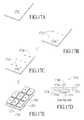
- FIGS. 7A-7Eillustrate another technique for forming a keypad or keyboard, under an embodiment of the invention.
- FIG. 8Ais an isometric view of a keyboard separated from a mobile computing housing, according to an embodiment of the invention.
- FIG. 8Bis an isometric view of a mobile device housing for a keyboard, under an embodiment of the invention.
- FIG. 9is a frontal view of a mobile computing device, configured according to an embodiment of the invention.
- FIG. 10illustrates a frontal and bottom isometric view of the mobile computing device 900 , according to an embodiment of the invention.
- FIG. 11illustrates basic components of a stack assembly for use with a keypad or keyboard of a mobile computing device.
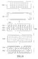
- FIG. 12Aillustrates an actuation member for use with a stack, under an embodiment of the invention.
- FIG. 12Billustrates a design for a electrical contact layer, under an embodiment of the invention.
- FIGS. 13A and 13Billustrate a stack formation, under an embodiment of the invention.
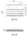
- FIGS. 14A and 14Billustrate an alternative design for a stack, under an embodiment of the invention.
- FIGS. 15A and 15Billustrate an alternative construction in which a mask is combined with an illumination layer 410 as part of a stack formation, under an embodiment of the invention.
- FIG. 16is a frontal view of the different layers and elements that can be used to integrally form a modular stack, under an embodiment.
- FIGS. 17A-17Eillustrate another technique for forming an actuation member layer, under another embodiment of the invention.
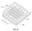
- FIG. 18illustrates an embodiment of the invention implemented within a mobile computing device having a first keyboard design.
- FIG. 19illustrates an embodiment of the invention implemented within a mobile computing device having a second keyboard design.
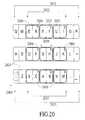
- FIG. 20illustrates a keyboard configured for implementation with a number assignment technique, according to an embodiment of the invention.
- FIG. 20illustrates a keyboard configured for implementation with a number assignment technique, according to an embodiment of the invention.
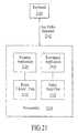
- FIG. 21illustrates a system in which keys or key structures can be paired (or clustered) to provide a single numeric value, or separate non-numeric values.
- FIG. 22illustrates a mobile computing device, configured with a key assignment scheme in accordance with an embodiment of the invention.
- Embodiments of the inventionprovide an effective keypad assembly and keypad layout for mobile computing devices.
- embodiments of the inventionprovide keyboard layouts and designs.
- embodiments described hereinprovide for stack components to make keyboards operable on small-form factor devices.
- a small form-factor keypadis provided that prioritizes available housing real-estate for the area occupied by individual keys.
- the resultis larger keys and/or smaller sized mobile computing devices, at least compared to past approaches for placing keypads and keyboards on such devices.
- a modular stack assemblyfor making small-form factor keyboards operable on mobile computing devices.
- a technique and designis provided to facilitate users in making number entries on small form-factor keyboards.
- a mobile computing devicemay implement a keyboard design such as described with FIG. 1 , but omit use of a stack assembly such as described by other embodiments of the invention. Numerous variations and implementations for embodiments of the invention are described in this application.
- Embodiments described hereinprovide a keyboard having keys that are tightly spaced in at least one direction (e.g. the horizontal direction). This promotes a small overall form factor for the mobile computing device and/or larger keys on the device.
- Several features and considerationsare implemented with a keyboard design of one or more embodiments of the invention. These features and considerations include (i) a shape or footprint of individual keys that form the keypad, (ii) a spacing between adjacent and neighboring keys in the keypad (e.g. a horizontal spacing between adjacent keys of a row), and/or (iii) a spacing between adjacent sets of keys (e.g. a vertical spacing between rows of a keyboard).
- One result achieved by an embodiment of the inventionis that a larger percentage of a housing surface can be used for the individual keys that comprise a keyboard of the mobile computing device. This enhances the usability of the keypad, particularly in the user's ability to see and select keys using finger tips and pointed objects.
- a mobile computing devicehaving a housing on which a keypad is provided.
- the keypadmay be formed from a plurality of key structures that extend from a surface or region of the housing. Individual key structures that form the keypad are moveable inward, so to move from an original position into an engaged position. When moved into the engaged position, processor(s) contained within the housing register an input, depending on the particular key structure that is engaged.
- a majority of the key structureshave a footprint that is oblong in shape to define a length and a width of that key structure. The footprint is also symmetrical about at least its length.
- Each key structure in the majorityincludes an outer surface that is provided with an outward curvature relative to the region of the housing.
- the keypadis a keyboard, with each key structure being assignable to a particular letter and/or character.
- key structures that form the keyboard that are most proximate to one another in a first directione.g. the horizontal direction
- the key structuresmay also be distributed linearly in the first direction, so that a dimension of the keyboard in the first direction corresponds substantially to a sum of a dimension of the individual key structures in the first direction.
- the term “substantially”means nearly equal, or at least 80% of a stated quantity or expression. Similar relational expressions, such as “about” or “approximately” should be considered to be 90% or more of a stated quantity.
- the expression “nearly abuts”means almost or nearly in contact.
- the expression “nearly abuts”means (i) two key structures are sufficiently separated to move independently; and (ii) the two key structures are proximate enough so that they appear to be in contact or abutting. Additional description and variations to the expression “nearly abutting” are provided below in this application.
- a keypadfor a mobile computing device.
- the keypadincludes a plurality of key structures that are distributed to extend in a horizontal direction and in a vertical direction on a face of the mobile computing device. For at least a majority of the plurality of key structures, individual key structures that are most proximate to one another in the horizontal direction nearly abut one another, while key structures that are most proximate to one another in the vertical direction are spaced apart. Additionally, individual key structures in the majority of key structures have a footprint that is oblong.
- the lengthwise direction of the footprint for the majority of key structurescorresponds to the vertical direction.
- the lengthwise direction of the footprint for the majority of key structuresmay be tilted about the vertical direction.
- spaced-apartmeans a spacing that is greater than what would appear to be abutting.
- Two key structures that are spaced apartmay be separated by a visible underlying surface or layer.
- the individual key size of a keyboard on a mobile computing deviceis maximized, or at least enhanced relative to the form factor of the mobile computing device.
- the key structuresare elongated to have length in a vertical direction, while a limiting dimension (e.g. the width) of the mobile computing device is in the horizontal direction.
- the use of elongated keys having lengths in the non-limiting dimension of the mobile computing deviceenables the individual key structures to be made larger, without need to increase the dimensions of the mobile computing device.
- the larger key sizeenables larger graphics and tactile feedback for the user. For example, the user has more key area to locate and select keys using fingertips.
- elongated key structuresthat are aligned with the non-limiting dimension of the mobile computing device also permit for the key structures to be shaped in a manner that is conducive to the user's touch and use.
- one embodimentprovides for individual key structures that are barrel shaped, so as to contour outward in symmetrical fashion.
- the contoured shape and dimension of individual keyshinders inadvertent finger movements by the user that may result in inadvertent strikes to neighboring keys.
- the contour shape providedenables the user to avoid finger slippage and to have a better feel for the key when making a key strike.
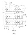
- FIG. 1illustrates a small-form factor keyboard for use with a mobile computing device, according to an embodiment of the invention.
- the keyboard 100is provided on a surface 102 of housing 110 for a mobile computing device.
- An example of a mobile computing device for use with embodiments of the inventionincludes cell phones, messaging devices and/or cell phone combination devices (e.g. a HANDSPRING TREO device, manufactured by PALMONE, INC.), and personal digital assistants.
- the keyboard 100includes a plurality of key structures 120 that are distributed to span in a horizontal direction (X) and a vertical direction (Y).
- the key structures 120are provided in a QWERTY layout on the surface 102 .
- key structures 120may be assigned a letter and possibly one or more alphanumeric characters, although some key structures may be assigned functions (e.g. Enter). The assignment of letters, functions (e.g. “Enter”) and other alphanumeric characters, may be displayed with the key structure 120 through artwork or print.
- 30 key structures 120are provided to accommodate 26 letters and 4 special keys or functions, although more or fewer can be included in the keyboard 100 .
- the key structures 120are distributed in at least three horizontal sets 122 .
- the horizontal sets 122are rows, or substantially linear in the horizontal direction (X). However, as described with other embodiments, the horizontal sets 122 may extend in the horizontal direction, while being staggered or arcuate (such as to form a “smile”).
- an overall horizontal dimension of each horizontal set 122consists primarily of a sum of the horizontal dimensions of the individual key structures in that horizontal set.
- a dimension of any horizontal set 122 represented by TWis substantially or approximately equal (e.g. within 90%) to a sum of a maximum width W of each key structure 120 in that horizontal set 122 .
- adjacent key structures 120 in each horizontal set 122nearly abut one another.
- the adjacent keysare nearly abutting if adjacent keys have the appearance of being abutting, when in fact individual each key structure 120 are separated from adjacent key structure that appear to be abutting.
- Adjacent key structuresmay appear to be abutting if no space or structure appears to separate the key structures.
- the key structuresmay appear to be abutting, sufficient separation does exist between abutting key structures which enables any key structure to be moved inward independently and freely of adjacent key structures that appear to be abutting. Thus, inward movement by one key structure 120 key does not translate to the nearly abutting key structure.
- a distance of separation for nearly abutting key structurescorresponds to a distance that is of the order of a tolerance level for assembling the housing and interconnecting components or layers (excluding the actual keypad)) to make the keyboard effective.
- the tolerance levelmay be tied to individual tolerances for assembling a stack assembly comprising an actuation member layer, illumination layer, electrical contact layer and/or any other layer or element for the assembled and integrated stack.
- the tolerance level of the stackmay comprise the sum tolerances provided by placement of each layer that forms the stack.
- a separation distance between nearly abutting key structuresis less than 0.6 mm, and more preferably, less than or equal to about 0.1 mm. In one implementation, a separation distance between nearly abutting key structures is about 0.05 mm.
- FIG. 1While an embodiment such as described by FIG. 1 provides for nearly abutting key structures 120 , it should be notes that other embodiments may provide for a greater separation between the adjacent key structures 120 of the horizontal sets 122 .
- the separation between adjacent key structures 120 of the horizontal sets 122may range to about 0.60 mm to 0.75 mm, so that the key structures 120 are tightly spaced, but not necessarily nearly abutting.
- FIGS. 4A and 4BAn example of such an embodiment is shown with FIGS. 4A and 4B .
- adjacent horizontal sets 122are separated from one another by strips 112 of housing 110 , forming regions of the surface 102 .
- key structures 120 that are nearest or most proximate to one another in the vertical direction (Y)are spaced-apart.
- individual key structures 120may extend or be supported underneath the housing 110 in the vertical direction (Y), as the horizontal sets 122 are sufficiently spaced apart to provide for the housing strips 112 .
- sub-layer extensionsmay extend from each key structure 120 , underneath the surface 108 and just under a top visible edge 127 and bottom visible edge 129 of that key structure. The sub-layer extensions hold in place on the housing the individual key structures and/or the keyboard (or portions thereof, depending on whether the key structures are provided on a carrier or carrier segments).
- keyboard 100as its spans the horizontal (X) and vertical (Y) directions may have several variations and alternatives.
- FIG. 1illustrates each horizontal set 122 being aligned in the vertical direction, other implementations may stagger each horizontal set.
- the horizontal sets 122may be provided with less linearity, such as in a curved or “smiley face” configuration, or staggered at one or more locations.
- individual key structures 120are shaped to occupy a greater amount of area on surface 108 of housing 110 .
- a majority of the key structures 120are each provided a footprint 128 that is oblong, and an exterior surface that has at least one outward curvature (see FIG. 2A and FIG. 2B ).
- the footprint 128corresponds to the two-dimensional space occupied by the key structure on the surface 108 of the housing 110 .
- the footprint 128 of a particular key structure 120e.g. the letter “I”
- the footprint 128is symmetrical about the lengthwise axis.
- the particular shape of key structures on the interior of the keyboardis rectangular.
- Other oblong shapes for footprints of key structuresare possible, such as elliptical or a rectangular/ellipse combination.
- a lengthwise direction 126 of the footprint 128 for the majority of key structures 120coincides with the vertical axis (Y) and the non-limiting dimension of the mobile computing device.
- the lengthwise direction 120 of the footprint 128 for the key structures 120may be tilted with reference to the vertical axis (Y).
- boundary key structures 121which are provided at the boundary of each horizontal set 122 , may have a different shape than the other key structures in the keyboard.
- the boundary key structures 121have the same length dimension, or shaped to be oblong, but are non-symmetrical.
- a boundary side 123 of each boundary key structure 121may be curved, rather than linear, so as to provide that key structure the non-symmetrical footprint.
- the keyboard 100may include numerous other key structures, such as application keys, number keys, a space bar etc. Many of these key structures may have different shapes and orientations.
- a majority of the key structures of the keyboardare shaped to include the oblong footprint and the symmetry about the lengthwise axis 126 .
- these key structures 120are non-boundary key structures that are assigned letter values and more likely to be heavily used.
- individual key structures 120may be provided with an outward curvature on an exterior surface 144 (see FIG. 2A and FIG. 2B ). When the thickness or height of the individual key structure is viewed, the exterior surface may be convex. As will be described, the outward curvature facilitates the user in making better key strikes, in part by providing a surface that hinders inadvertent finger slippage and movements.
- individual key structures 120(specifically, at least those with symmetrical and oblong footprints) are provided a curvature about one axis. In an embodiment, the curvature is provided about the lengthwise direction 126 of the individual keys, which in the example provided by FIG. 1 , corresponds to the vertical axis (Y).
- the curvaturemay be symmetrical, so as to coincide with a centerline of an individual key structure 120 .
- a resultis that the individual key structure 120 is “barrel shaped” so as to extend from surface 108 in the form of a partial cylinder.
- FIGS. 2A and 2Bare side cross-sectional views along respective lines A-A and B-B of FIG. 1 , according to an embodiment.
- the cross-section of FIG. 2Aillustrates adjacent key structures 120 of one of the horizontal sets 122 .
- Each key structure 120may extend a height h above the surface 108 .
- a key structure portion 141 extending from surface 108is includes a rectangular base 143 and the exterior surface 144 having an outward curvature (e.g. convex), so as to form a cylindrical area over the surface 108 .
- the curvature of key structures in FIG. 2Ais about the vertical axis (Y).
- the portion 141 extending from surface 108may omit the rectangular base and provide only the outward curvature. The user may make contact with a finger or stylus to the exterior surface 144 to direct the individual key structure inward into the housing 110 , causing actuation of that key.
- the exterior surface 144has a peak 146 at a centerline of the key structure, with a symmetrical inward curvature 147 that extends from peak 146 towards the lateral edges 148 , 148 of the individual key structure 120 .
- a horizontal distance between lateral sides 148 , 148represents the width W of the key structure 120 .
- a separation t between adjacent key structures 120 in the horizontal sets 122may be reduced or minimized, so that the key structures are nearly abutting.
- the separation represented by tis less than 0.1 mm, and preferably between 0.04 mm and 0.06 mm. In one implementation, this distance is about 0.05 mm.
- Other embodimentsenable greater separation between key structures, while maintaining the nearly abutting relationship between adjacent horizontal key structures.
- the key structuresmay be up to 0.7 mm spaced apart.
- a bottom portion 149 of the key structure 120may extend underneath the surface 108 of the housing.
- the bottom portion 149may be aligned with and/or connected to a corresponding actuation member 152 that move inward with insertion of the key structure 120 .
- the corresponding actuation member 152makes contact with an aligned electrical contact, thereby actuating an electrical signal to processing resources of the computing device.
- the alignment of each key structure, its corresponding actuation member 152 , and the aligned electrical elementenable processing resources of the mobile computing device to correlate key strikes to a particular value, such as a particular letter of the alphabet.
- the actuation members 152are joined or integrated with the corresponding key structures 120 .
- each actuation membermay be molded or otherwise formed into a bottom surface of the corresponding key structure.
- the actuation members 152may be separately formed from the key structures 120 .
- the actuation members 152may form part of a stack assembly that is inserted underneath the keyboard 100 .
- Such a stack assemblymay also include the aligned electrical contacts, as well as an illumination layer.
- the distance tmay be less than or equal to the tolerance level for assembling the stack for the keyboard 100 .
- each key structure 120extends the height h from the surface 108 with no curvature.
- the length L of the key structure 120may be defined as a distance between a top edge and a bottom edge 127 , 129 of the key structure 120 .
- the key structures 120may extend from openings 154 formed in surface 108 of the housing 110 .
- each opening 154is extends lengthwise in the horizontal direction (X) to accommodate an entire horizontal set 122 .
- each opening 154may accommodate only an individual key structure 120 , or some other combination of key structures.
- the key structure 120may include extensions 155 that extend underneath an interior formation 156 of the housing 110 .
- the interior formation 156may provide additional space to accommodate lateral extensions 155 of the key structure 120 .
- the interior formation 156overlays the lateral extensions 155 to prevent the key structure from falling out of the housing 110 .
- individual key structures 120have housing support on their respective vertical edges, but not their lateral edges 148 , 148 .
- lateral extensions 155 of the key structures 120extend underneath the housing 110 at edges 151 , 153 .
- a distance Tseparates proximate key structures 120 in the vertical direction (Y). According to an embodiment shown by FIG. 1 , the distance T separates adjacent horizontal key sets 122 .
- the housing strip 112occupying an area extending the distance T, may be visible to the user.
- the distance Tmeasures between 1.0 and 5.0 mm, and more preferably between 2.0 and 4.0 mm.
- insertion of the key structure 120causes actuation member 120 to move inward and trigger an electrical contact.
- Mechanismssuch as described in FIG. 2A (e.g. integrated actuation member 152 ) or elsewhere in this application (e.g. modular mechanical stack) may be used to correlate insertion of the key structure 120 and actuation of a corresponding electrical signal.
- individual key structures 120may be provided on one or more carriers or carrier strips.
- the key structures 120may be molded, joined or otherwise connected or integrated to a single carrier 159 .
- the single carrier 159may extend underneath the housing 110 in both the X and Y direction.
- the carrier for the key structures 120may be in the form of a strip that extends to provide key structures for individual horizontal sets 122 .
- a spacing structure or formationmay be provided at the juncture of the curved exterior surface 145 and the lateral edges 108 .
- the spacing formationmay be in the form of a groove or scallop.
- FIG. 2Cillustrates an implementation of the groove 160 (or scallop) at the juncture of each of the lateral edges 148 , 148 and the exterior surface 144 .
- the formationenables the user to see and/or feel (through fingers) further separation between adjacent key structures 120 in the horizontal set 122 .
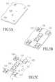
- FIG. 3Ais an illustrative isometric view of an isolated key structure 220 , according to an embodiment of the invention.
- the key structure 220has a base 210 that extends at least partially into the housing 110 (see FIGS. 2A and 2B ).
- An exterior surface 244extends over the base 210 , forming a cylindrical or barrel shaped surface to meet the user's finger tip or stylus.
- the key structure 210is provided with an ornamentation 212 that is printed or otherwise formed on the exterior surface 245 . In one embodiment, an up-down orientation of the ornamentation 212 coincides with the vertical direction (Y) (SEE FIG. 1 ).
- ornamentation 212may also be elongated, making the letter and/or characters assigned to the individual keys larger and more viewable to the user.
- the key structure's lengthwise direction 242also coincides with the vertical direction (Y).
- a curvature of the exterior surface 244is provided about the lengthwise direction 242 , with the peak of the curvature appearing at the centerline of the exterior surface 244 .
- lateral grooves 248 , 248may be provided to facilitate the user's ability to separate and select adjacent key structures in the horizontal direction (Y).
- the lateral grooves 248 , 248may extend the length of the key structure 120 .
- the particular type of space formationmay vary.
- FIG. 3Bis an illustrative isometric view of a key structure 220 , with an alternative outward appearance.
- the ornamentation 212is provided within or underneath a body 268 of the key structure 220 .
- the body 268 of the key structure 220may be formed from a clear or translucent material, such as a clear plastic.
- the ornamentation 212may be formed on a surface 214 or region underneath the body 268 , such as on a film layer (see e.g. FIGS. 5A-5G ).
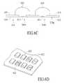
- FIG. 4Aillustrates an alternative keyboard layout that does not employ use of nearly abutting key structures, according to another embodiment of the invention.
- a keyboard 300may incorporate horizontal key sets 322 similar to a configuration such as shown in FIG. 1 , except that adjacent key structures 320 in the horizontal key sets 322 are not nearly abutting one another. Rather, a spacing R may exist between adjacent key structures 320 in the horizontal sets 322 . The spacing may be sufficient in dimension to allow users to view into a gap formed by the adjacent key structures 320 . A housing structure in the spacing R, or a space interior to the housing may be readily viewable to the user.
- the adjacent key structures 320 in each horizontal key set 322may be closely spaced, but still separated by a distance that is non-abutting. Even if the key structures 320 are considered non-abutting, a relationship where TW is substantially or approximately equal (within 80% or 90%) of the sum of the individual maximum widths W may still hold true.
- the adjacent key structures 320 in each horizontal key set 322are spaced by a distance that exceeds 0.75 mm.
- the range of separation between adjacent key structures 320is between 0.75 and 1.5 mm, and more preferably of the range of 1.0 mm.
- the separated distance between the key structures 320may refer to a minimum distance between the two structures as they extend above the surface of the housing.
- FIG. 4Billustrates adjacent key structures 320 of one of the horizontal key sets 322 in the keyboard 300 .
- the adjacent key structures 320are separated by the distance R, which is sufficient in dimension to not provide the appearance of being abutting. As such, this distance permits the user to view an underlying space or region between the key structures 320 .
- the distance Ris still sufficiently small to avoid the need for providing the housing surface 108 in between the key structures in the horizontal sets 322 .
- the dimensions of the key structures 320may be made more narrow in the horizontal direction to make extension of the housing surface 108 in between the key structures of the horizontal sets 122 practical.
- FIG. 5A-5Gillustrate a manufacturing process for producing a keyboard having nearly abutting key structures, as described with FIG. 1 and FIG. 2A-2B , under an embodiment of the invention.
- a process such as described in FIG. 5A-5Gallows for individual key structures to be placed sufficiently close to one another so as to qualify as being “nearly abutting”.
- a process illustrated by FIG. 5A-5Gcreates separated sets of key structures that are interwoven together as part of the assembly process to form a keyboard 100 such as described in FIG. 1 .
- Such a manufacturing techniqueprovides an alternative to using standard molding techniques for forming the individual key structures of the keyboard 100 , as standard molding techniques are difficult to implement in a manner that allows key structures to be spaced by a distance that is nearly abutting to another key structure.
- the use of interweaving patterns to assembly separate key structure groups into one keyboardenables adjacent key structures 120 in the horizontal sets 122 of keyboard 100 to be placed sufficiently close to one another to be nearly abutting.
- any reference to a numeral of FIG. 1is intended to illustrate a suitable or descriptive element for a particular step or process.
- a thin film 510 formed from polycarbonate or other flexible materialis used as a base for individual key structures.
- a print or silkscreen imageis created on the film to provide the ornamentations 512 that are to be placed on the individual key structures.
- the ornamentations 512are in the form of letters, although other ornamentations such as numbers and alternative characters may be printed on the film 510 .
- the placement of the ornamentations 512coincides with where individual key structures are to be formed that carry those ornamentations.
- the individual key structureswill be formed in separate groups or sets that are subsequently interwoven together. The location where each key structure is to be formed is dictated by an interwoven pattern used, and not necessarily by the relative position of that key structure relative to other key structures in the keyboard layout (e.g. QWERTY layout).
- FIG. 5Ba manufacturing step is shown where individual key structures 520 are formed on the film 510 at locations where corresponding ornamentations are provided. Each key structure 520 is formed over one of the ornamentations, so that is carries that particular ornamentation.
- each key structure group 515 , 525includes three key structures 520 .
- the particular interweaving pattern used in the example providedis one where each key structure group 515 , 525 includes at (i) at least two keys from a given horizontal set 122 in the keyboard 100 ; (ii) the two key structures are in the given horizontal set are not adjacent to one another in the keyboard layout, but rather separated by at least one other key; and (iii) at least one key structure from another one of the horizontal sets 122 .
- a void 523exists between two key structures 520 of the same horizontal set 122 .
- a cut-out strip 512 of film 510is used to join the key structures 520 of each group 515 , 525 .
- the strip 512extends a length to join the key structures 520 from the different horizontal sets. This length is about equal to the vertical separation between the horizontal sets 122 when the keyboard is formed.
- the particular interweaving pattern used to form each key structure groupis one of design choice. For example, other patterns may provide for key structure groups to include only key sets from a single row or horizontal set of keyboard 100 .
- FIG. 5Dis a side cross-sectional views cut along lines C-C of FIG. 5C , showing a cross-section of key structure group 515 .
- the strip 512extends between and join key structures 520 from different horizontal sets 122 .
- the strip 512is formed to include an upward bend 514 and plateaus 518 on opposite sides of the upward bend 514 .
- a differential t 2represents the differential between the upward bend 514 and the plateaus 518 .
- the upward bend 514separates the key structures 520 , with individual key structures 520 provided on each plateau 518 .
- FIG. 5Eillustrates another one of the key structure groups 525 with strip 512 joining key structures 520 .
- This key structure group 525is to be interlaced or weaved with the key structure group 515 of FIG. 5D .
- key structure group 525is provided with a downward bend 524 to adjoin key structures 520 on different horizontal sets 122 .
- Each key structure 520is provided on a corresponding plateau 518 that is raised with respect to the downward bend 524 by the differential t 2 .
- FIG. 5Fillustrates a midframe 540 to hold two or more key structure groups 515 .
- the midframe 540includes openings 542 to hold key structures that eventually hold key structures of a common horizontal set 122 .
- FIG. 5Gillustrates that key structure groups 515 , 525 are assembled in an interwoven fashion about the midframe 540 .
- the strip 512 of one of the key structure groups 515may be attached to a topside 544 of the midframe 540 , with the key structures 520 of the group hovering in the openings 542 of the midframe.
- the strip 512 of the key structure group 525may be attached to an underside (not shown) of the midframe 540 , with its key structures 520 extending out of the respective openings 542 .
- the upward bend 514 and downward bend 524enable the key structures 520 of the respective groups 515 , 525 to be assembled in the interwoven manner about the midframe 540 , without the strip 512 of one key structure group being in conflict with the strip of another key structure group. Rather, in the example provided, the strip 512 of the key structure group 515 is provided above the midframe 540 , while the strip of the key structure group 525 is provided below the midframe 540 . Once the strips 512 of each respective key structure group 515 , 525 are connected to the midframe 540 , the key structures 520 of the respective key structure groups float in the space provided by the openings 542 , enabling each of those structures to move inward.
- a manufacturing process for forming a keyboard such as described in FIG. 5A-5Genables a separation distance between adjacent key structures to be tighter than what would normally be allowed should key structures be formed through standard molding techniques.
- a process such as described in FIG. 5A-5Gmay be used to place key structures 520 within 0.05 mm of one another, while a traditional molding technique would require the key structures to be separated by a distance no less than 0.5 mm.
- FIGS. 6A-6Dillustrate a different manufacturing process for forming a keyboard comprised of key structures, according to an embodiment of the invention.
- FIG. 6Aa film of polycarbonate or similar material 610 is provided holes 612 where corresponding key structures 620 are to be formed.
- the holes 612are used to provide material for molding the individual key structures 620 .
- FIG. 6Billustrates the formation of the key structures 620 over the corresponding holes 612 .
- FIG. 6Cillustrates how individual key structures 620 are formed over the film 610 using a molding process.
- a material for forming the key structures 620is passed from the underside 616 of the film 610 through each of the respective holes 612 . This may be accomplished by positioning gates for shooting the material against each hole 612 on the underside 616 . The material is then passed through the individual hole 612 and used to form the key structure 620 on a topside 618 of the film 610 .
- the material pushed through the film 610 to form the individual key structures 620is a resin material.
- the materialmay be made translucent or milky in order to make the ornamentations provided by the key structure 620 more noticeable, as well as to enable illumination from under the film 610 to illuminate the key structure 620 .
- An ornamentation 622 on each key structuremay be made through a surface printing of the corresponding key structure after that structure is formed.
- the ornamentationmay be formed on the film 610 before the formation of the key structure 620 .
- the ornamentation 622 for each key structure 620may be formed on the film at the region where each hole 612 is provided.
- the material used to form the key structure 620may be translucent (e.g. clear resin), so that the ornamentation 622 underneath the key structure is visible, particularly with illumination from underneath the key structure 620 .
- a manufacturing process such as shown by FIG. 6A-6Denables more precise formation of key structures 620 than would otherwise be possible using more traditional or common molding techniques.
- a process such as shown by FIGS. 6A-6Dmay yield spacing between key structures as described with, for example, embodiments of FIG. 1 and FIG. 4A .
- FIG. 7A-7Eillustrate another technique, in which a molding process can be used to form the individual key structures 720 , with ornamentation provided through an underlying film 710 .
- a film 710(e.g. polycarbonate material) is formed to include ornamentations 712 .
- the ornamentations 712are printed on an underside 716 (or backside) of the film 710 .
- the film 710may be formed from translucent material to enable the ornamentations to be visible from the topside 718 of the film 710 .
- FIGS. 7B and 7Cillustrate that key structures 720 are formed using gates 730 on the topside 718 of the film 710 .
- the resulting key structures 720may be formed through the gates to include a key structure shape.
- the gatesmay be provided on the same side of the film 710 as the key structures that result from the molding process.
- Each key structure 720may include a base region 722 over film 710 to stabilize the key structure on the film.
- FIG. 7Dshows an optional step where film 710 is cut or slit.
- a resulting slit patter 732is provided.
- the slit patter 732consists of slits that extend in the horizontal direction, so as to separate horizontal sets 122 .
- the slit pattern 732may improve the cleckability of the individual key structures 720 .
- FIG. 7Eshows the completed keyboard, with key structures 720 molded on the topside 718 of the film 710 , and ornamentation 712 provided on the underside 716 of the film 710 .
- Separate rows 750 (or horizontal sets) of key structures 720are provided.
- the spacing between adjacent key structures in a given row 750may vary. In one embodiment, the spacing is of the range of 0.3-1.0 mm, so that the individual key structures are close, albeit not nearly abutting.
- FIG. 8Ais an isometric view of a keyboard separated from a mobile computing housing, according to an embodiment of the invention.
- the keyboard 800includes key structure rows 812 , 814 , 816 and 818 , where key structures 820 that comprise the rows are arranged in a QWERTY layout.
- the perspective shown in FIG. 8Aprovides the first row 812 containing the “QWERTY” keys as being the most proximate.
- Each key structure 820includes a base 822 and an exterior surface 824 .
- the base 822may at least partially reside within a housing of the mobile computing device.
- the key structures 820may be provided on a carrier 815 , or a combination of carrier strips that interconnect two or more of the key structures.
- the exterior surface 824may include an outward contour along the vertical axis Y.
- each key structure 820is provided a barrel or cylindrical shape on its exterior.
- a minimum horizontal distance 825 between the base 822 of adjacent key structures 820 of each row 812 - 818is sufficiently small (e.g. 0.05 mm) to give each key structure 820 the appearance that adjacent key structures are abutting.
- dimension of horizontal distance 825may be sufficiently small to preclude users from seeing between the bases 822 of the adjacent key structures 820 .
- a minimum vertical distance 835 between key structures 820 adjacent rowsdoes not give the appearance that the key structures are abutting.
- a housing section, or an underlying surface of the keyboard extending the vertical distance 835 of proximate key structuresmay be plainly visible to sight.
- FIG. 8Aprovides for formation of a groove 840 or scallop on lateral edges of each key structure.
- Each groove 840may separate the key structure 820 from an adjacent key structure in the row-wise direction.
- FIG. 8Billustrates a mobile computing device housing 870 , for use with an embodiment of the invention.
- the housing 870may include a plurality of openings 860 to accommodate horizontal sets of key structures (e.g. horizontal sets 122 in FIG. 1 ).
- the openings 860may extend in the X direction to accommodate the entire width (TW in FIG. 1 ) of the horizontal set.
- the openings 860contain no intersecting housing structure to separate or laterally support adjacent key structures.
- the keyboard 800for example, may be coupled with the housing 870 so that the individual key structures 820 extend from a surface 862 of the housing. No horizontal support is provided between key structures 820 (other than the carrier 815 ).
- the absence of horizontal support and intersecting housing structures within openings 860provide one mechanism by which key structures can be made nearly abutting.
- the openingsare spaced by the housing surface 162 , which provides a clearly visible separation between key structures in the vertical direction.
- FIG. 9is a frontal view of a mobile computing device, configured according to an embodiment of the invention.
- a device 900such as shown in FIG. 9 may have both text-messaging capabilities (e.g. email, instant message, etc.) and cellular-voice capabilities. As such, the device 900 requires both keyboard 910 and cellular phone functionality. Despite the dual functionality of the device 900 , the device is provided dimensions that are more in accordance with traditional cellular phones. A width (along axis X′) of the computing device 900 is the limiting dimension. As such, features of the mobile computing device that require the most area are elongated.
- the display 930 and individual key structures 920 of keyboard 910are elongated in alignment with a length of the device 900 (along axis Y′).
- the keyboard 910may be configured similar to embodiments such as described with FIG. 1 and FIG. 4A .
- a dimension of the keyboard 910may extend almost all of the width of a front panel 915 of the device 900 .
- the width of the keyboard 910is substantially equal to the width of the mobile device 900 .
- individual key structures 920may be tightly spaced (either to be abutting or non-abutting), so that each key structure can have a maximum individual width.
- the resultis a combination of relatively large key structures 920 on mobile computing device, having dimensions (specifically width) that is substantially that of a traditional cell phone.
- the size of the computing devicein combination with the dimensions of the keyboard 910 and individual key structures 920 , allows for the user to hold the mobile computing device in one hand while readily operating the keyboard with that same hand.
- FIG. 10illustrates a frontal and bottom isometric view of the mobile computing device 900 , according to an embodiment of the invention.
- the individual key structuresare tightly spaced together in the row-wise direction, either in abutting or non-abutting fashion.
- Each key structure 920is provided a barrel shaped exterior, having an outward curve. This facilitates the user's selection of keys when operating the keyboard 910 .
- Embodiments described hereinprovide for a modular or integrally assembled stack that can be used to make keypads of mobile computing devices operable.
- Embodiments such as described with FIG. 11may be implemented in conjunction with a keyboard layout embodiment such as described with FIG. 1 and FIG. 4A .
- a stack such as described by embodiments of the inventionmay also be used with numerous other types of keypads or keyboards, including keyboards or keypads that are not included with embodiments of the invention.
- a stack assemblyfor use with a keyboard or keypad of a mobile computing device.
- the stack assemblyincludes an electrical contact layer, and actuation member layer, and an illumination layer.
- the electrical contact layerincludes a plurality of contact elements.
- the actuation member layerincludes a plurality of actuation members are, wherein each actuation member is aligned so that an axial movement of that member causes a corresponding one of the plurality of contact elements to actuate.
- the illumination layeris configured to emit light to the keypad.
- axial movementalso means vertical movement, or movement in a direction that is inward with respect to a housing of the mobile computing device.
- a layerrefers to an occupied thickness.
- a layermay include more than one type of material, including sub-layers (e.g. underlying film).
- a mobile computing devicehaving a housing, one or more processors contained within the housing, and a keyboard comprising a plurality of key structures provided on a surface of the housing.
- a modular stack assemblymay be contained within the housing and operatively engaged with the keyboard to enable each of the plurality of key structures to be operated to register input with the one or more processors.
- integralor “integrally combined” mean that elements or components are combined to form a single or modular unit.
- different materials and fabrication processesmay be used to integrally form a stack, but after its formation, the stack may be treated as a single or modular unit.
- operatively engagedmeans that two elements are coupled in a manner that is operative, assuming electrical power is provided if needed for operation of the coupled elements.
- FIG. 11illustrates basic components of a stack assembly for use with a keypad or keyboard of a mobile computing device.
- a stack 100includes an illumination layer 1110 , an actuation member 1120 , and an electrical contact layer 1130 .
- FIG. 11illustrates one simplified arrangement for the layers, with illumination layer 1110 provided most proximate a surface of a housing 1103 on which key structures 1108 of a keyboard 1105 (or other type of keypad set) are provided.
- the key structures 1108may be extended from the housing 1103 through corresponding openings or apertures formed in the housing.
- the stack 1100electronically interconnects or interfaces the keypad 1105 with a processor 1150 or processing resources of the mobile computing device.
- the illumination layer 110includes lighting resources that illuminate the keyboard 1105 , or at least individual key structures 1108 in the keyboard 105 .
- the electrical contact layer 1130provides individual contact elements 1132 that are electrically interconnected via a printed circuit board, flex circuit, or other mechanism, to processing resources of the mobile computing device. Each contact element 1132 may be assigned to one of the key structures 1108 .
- the actuation member layer 1120includes individual actuation members 1122 that are aligned with a corresponding contact element 1132 and key structure 1105 . Each individual actuation member 1122 travels with insertion of the corresponding key structure 1105 into the corresponding contact element 1132 , causing that contact element to be switched or otherwise actuated. The result is that the processing resources of the mobile computing device are provided a signal corresponding to insertion of the particular key structure 1108 .
- FIG. 11illustrates a particular order of placement of the layers in the stack 100
- other arrangements and ordering of the different layers of the stackare possible.
- other componentsmay comprise the stack 100 . Some of these arrangements are described below.
- each layermay be fixed, joined or statically placed to an adjacent layer, so that the layers that form the stack assembly or integrally combined.
- the integral formation of the stack 1100means that the stack assembly can be treated as single unit, or as a module. As such, it is possible for the stack 1100 to be assembled separately from other components of a mobile computing device. For example, stack 1100 may be assembled as part of an original equipment manufacture (OEM) process. Subsequently, stack 1100 may be inserted as a modular component into the housing of the mobile computing device during a separate manufacturing or assembly process.
- OEMoriginal equipment manufacture
- Numerous mechanisms and meansmay be employed in order to affix or statically interconnect the different layers of the stack 1100 .
- embodiments described belowemploy adhesives to affix one layer of the stack 1100 to another layer.
- Other mechanismssuch as mechanical fasteners (e.g. screws, clips, snap-on couplings) may also be employed to secure one layer with another.
- each layer that forms the stack 1100may align to enable each key structure 1108 to be insertable and cause the corresponding element 1132 on the electrical contact layer 1130 to actuate.
- the actuation members 1122enable key structure insertion and/or travel to translate into actuation of the corresponding electrical element 1132 .
- the electrical contact layer 1130 and the actuation member layer 1120may be aligned so that each key structure 1108 of the mobile computing device is insertable to effectuate an input with processor 1150 .
- the processor 1150may correlate the electrical contact element 1132 switched with the corresponding input.
- the illumination layer 1110may also be aligned with the key structure 1108 so that light-emitting sources align with corresponding key structures 1108 .
- alignment structures and mechanismsmay be used to align the layers of the stack 100 during its formation.
- alignment pins and pin holes, ridges, and/or optical markersmay be used to align one of the layers in the stack assembly 1150 with an adjoining layer.
- the illumination layer 1110illuminates the keyboard 1105 from within the housing 1103 of the mobile computing device.
- the illumination layer 1110provides a medium on which light-emitting material or elements are provided.
- at least some of the key structures 1108 forming the keyboard 1105may be made of translucent materials so that illumination from within the housing 1103 results in the key structures being illuminated to the user.
- regions in the keyboard 1105such as around perimeters of individual key structures, may be illuminated.
- the illumination layer 1110is formed from electroluminescent (EL) material.
- the EL material illuminatesmay uniformly (or substantially thereof) illuminate across at least one or more regions of the illumination layer 1110 .
- One result that can be achievedis that the keyboard 1105 may be sufficiently uniformly lit to avoid dark spots or darkened key structures 1105 .
- the illumination layer 1110may be formed from another type of lighting source.
- the illumination layer 1110may comprise a carrier that is provided discrete light sources, such as light-emitting diodes (LEDs).
- the carrier of the illumination layer 1110may be formed from any material capable of carrying the light sources and the electrical conductivity to those sources.
- the LEDsmay be patterned on the surface of the illumination layer 1105 to illuminate the individual key structures 1105 from underneath. Various patterns may be used to distribute the LEDs on the illumination layer 1110 .
- other types of illumination sourcesmay be used, such as incandescent light sources.
- FIG. 12Aillustrates a general design for the actuation member layer 1120 , according to an embodiment of the invention.
- the actuation member layer 1120includes a carrier 1124 from which the plurality of actuation members 1122 are provided. As illustrated by FIG. 11 , each actuation member 1122 is aligned with a corresponding key structure 1108 and a corresponding contact element 1132 of the electrical contact layer 1130 . When a given key structure 1108 travels inward, that key structure 1108 may direct the corresponding actuation member 1122 into the contact element.
- the actuation members 122extend inward from the carrier 1124 towards corresponding contact elements 1132 of the electrical contact layer 1130 . However, it is also possible for a portion of the overall length of each member 1122 to extend upward towards the key structure 1108 .
- the carrier 1124may extend under the keypad 1105 to provide individual actuation members for each key structure 1108 .
- the carrier 1124enables the actuation members 1122 to be separately formed from the key structures 1108 and the electrical contact layer 1130 . This is in contrast to some past approaches, where actuation members are formed as part of the key structure 1108 , such as through extensions formed off of the bottom surfaces of the key structures.
- the carrier 1124may be aligned and affixed to the electrical contact layer 1130 as part of an assembly process for the overall stack 1100 . Subsequently, the carrier 1124 may be aligned with the keyboard 1105 of the mobile computing device in a separate assembly process.
- the individual actuation members 1122may be formed to be substantially more rigid than the carrier 1124 .
- the carrier 1124is made from an elastomer or other flexible or compliant membrane to reduce resistance to inward travel by the actuation members 1122 , and the actuation members 1122 are made rigid to be responsive to a user inserting the corresponding key structure.
- An example of a construction for the carrier 1124is a thin sheet of silicon-rubber.
- slits or cutsmay be formed onto the carrier 1124 in order to enhance the flexibility of the carrier 1124 .
- three cutsmay partially surround each member 1122 . The cuts lessen the overall resistance provided by the carrier 1124 when the key structure 1108 directs the member 1122 inward.
- the actuation member 1122 and the carrier 1124are formed from an elastomer such as silicon-rubber or polycarbonate materials.
- the carrier 1124 and the individual actuation members 1122are formed from different materials that may be combined or otherwise joined, such as the silicon-rubber and hard plastic respectively.
- various techniquesmay be used to form the actuation member layer 1120 independent of the other layers in the stack 1100 . For example, a co-molding process may be used to mold the hard or rigid material of the actuation member 1122 with the flexible material of the carrier.
- the actuation members 1122may be separately joined to the carrier 1124 using adhesives or other forms of chemical bonds.
- an overall area of the actuation members 1122is smaller than a footprint of the corresponding contact element 1132 .
- the ratio of a diameter of the actuation member 1122 to a diameter of the corresponding contact element 1132is less than 1:2, and preferably of the range of 1:4.
- An overall length of the actuation member 1122is sufficient to actuate the corresponding contact element 1132 . In one implementation, this length is about 0.5 mm. In an implementation such as described with FIG. 12B , where contact elements 1132 are snap-domes, the overall height needed is about 0.3 mm, corresponding to the separation of the outer contact surface 1135 ( FIG. 12B ) from the inner surface 1136 ( FIG. 12B ).
- the electrical contact layer 1130includes a substrate 1134 , such as a printed circuit board or a flex circuit, on which the electrical contact elements 1132 are provided. Circuitry provided by the substrate 1134 may interconnect the electrical contact elements 1132 with the processor of the mobile computing device.
- FIG. 12Billustrates one of the electrical contact elements 1132 provided on the substrate 1134 .
- the electrical contact elements 1132is snap-dome contact, having an outer contact surface 1135 and an interior contact 1136 .
- the outer contact surface 1135may bend or curve outward over the interior contact 1136 .
- the outer contact surface 1135 and the interior contact 1136may form a switch that can be actuated. In the absence of an external force, the switch is in an open state.
- Contact by the corresponding actuation member 1122causes the outer contact surface 1135 to collapse inward, thereby making contact with the interior contact 1136 .
- this contactcloses the switch formed by the outer contact surface and the interior contact 1136 .
- the processoris signaled a “key-down” event that indicates insertion of the corresponding key structure 1108 .
- the snap-dome constructionprovides a tactile sensation when actuation occurs.
- This sensationis in the form of a “snap”, felt with the collapse of the outer contact surface 1135 .
- the sensationinforms the user that a key-down event was registered, so that the user can concentrate on viewing the key structures, and not the display of the mobile computing device.
- FIG. 12Billustrates the contact element 1132 partially covered with a sheath layer 1138 .
- the sheath layer 1138is commonly used to enhance the tactile response that would otherwise be generated from the collapse of the outer contact surface 1135 .
- the sheath layer 1138is formed from a material such as MYLAR, which is semi-rigid but collapsible.
- the sheath layer 1138is normally affixed over an entire surface of the outer contact area 1135 .
- the actuation member 1122may make contact with the sheath layer 1138 to cause the collapse of both the sheath layer and the outer contact surface 1135 , thereby enhancing the snap response for the user.
- the sheath layer 1138may include an opening 1139 to receive the corresponding actuation member 1122 .
- the actuation member 1122makes direct contact with the outer surface 1135 , rather than with the sheath layer 1138 .
- Less resistanceis thus provided to the actuation member 1122 in making the snap-dome contact snap.
- the sheath layer 1138may be affixed to the outer contact surface 1135 so that inward movement of that surface causes the sheath layer 1138 to further enhance the snap-sensation.
- the enhanced tactile sensation provided by the sheath layer 1138may be preserved, while less resistance is given to the user inserting the corresponding key structures.
- each layer that forms the stack 1100may be integrated into the stack at a specific tolerance level or margin of error.
- the tolerance of each layer in the stack assemblyis tied together.
- the actuation members 1122are always aligned to make contact and actuate the corresponding electrical contact 132 .
- Thisis a direct result of assembling the stack as an independent unit.
- the electrical contactscorrespond to snap domes
- the result of the tolerances in the layer of the stack being tied togetheris that the actuation members and domes remain perfectly aligned, ensuring both good electrical contact and tactile feedback.
- the tolerance for the integration of each layer in the stackmay be cumulative, so that the overall tolerance of the stack 1100 is the sum, or at least the accumulation of the different tolerances.
- the tolerance level of the stack as a wholemay correspond to the order of the separation between key structures 120 in the horizontal sets 122 .
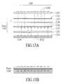
- FIGS. 13A and 13Billustrate a stack formation, under an embodiment of the invention.
- FIG. 13Aan exploded view of a stack 1200 is illustrated.
- the exploded viewillustrates the different elements that can be used to form an assembled and modular stack 1200 .
- the stack 1200may be placed underneath a keyboard 1205 comprising a plurality of key structures 1208 .
- ten key structures 1208are shown to simulate a row of a QWERTY keyboard.
- stack 1200includes an illumination layer 1210 positioned proximate to the keyboard 1205 , an actuation member layer 1220 provided underneath the illumination layer 1210 , and an electrical contact layer 1230 provided underneath the actuation member layer 1220 .
- FIGS. 11 , 12 A and 12 Billustrate suitable constructions and implementations of the illumination layer 1210 , actuation member layer 1220 , and electrical contact layer 1230 , under an embodiment.
- actuation member layer 1220may include a carrier 1224 on which a plurality of actuation members 1222 are provided.
- the electrical contact layer 1230may include a substrate 1234 having a plurality of electrical contact elements 1232 .
- one type of electrical contact elements 1232 that can be employedare “snap-dome” contact elements. Additional information for construction and formation of the actuation member layer 1220 is provided with FIG. 16 and FIG. 17A-17E .
- the illumination layer 1210 , the actuation member layer 1220 , and the electrical contact layer 1230are aligned and affixed to one another.
- a thin adhesive layer 1215affixes the actuation member layer 1220 to the illumination layer 1210
- a thick adhesive layer 1225affixes the actuation member layer 1220 to the electrical contact layer 1230 .
- the thin adhesive layer 1215is adhesive tape or film, such as VHB type adhesives manufactured by 3M.
- a thickness of the thin adhesive layermay range between 0.025 mm and 0.2 mm, and more preferably between 0.05 mm and 0.1 mm.
- the thick adhesive layer 1225may be positioned on the perimeter of the substrate 1134 and/or actuation member layer 1220 , so as to not contact any of the contact elements 1232 or actuation members 1222 .
- a suitable thickness for the thick adhesive layer 1225may range between 0.3 mm and 1.0 mm, and more preferably at about 0.8 mm.
- a suitable type of adhesive for this layermay be open cell foam adhesive, such as high-density open cell urethane foam with acrylic adhesive manufactured by 3M.
- the illumination layer 1210is formed from EL material. Placement of the illumination layer 1210 directly underneath the key structures 1208 permits maximum light output through the keypad 1205 and individual key structures 1208 .
- the key structures 1208may be formed from translucent or clear material, so as to act as light pipes that emit light from the illumination layer 1210 .
- FIG. 13Bis a side cross-sectional view that illustrates the placement of the assembled stack 1200 within a housing 1203 of a mobile computing device.
- Each layer that forms the stack 1200is affixed to the adjacent layers.
- the thick adhesive layer 1225may circumvent an interior region where the actuation members 1222 are positioned in contact or just above the electrical contact elements 1232 .
- the alignment of layers that comprise the stack 1200may be rigidly maintained, while the key structures 1208 have limited lateral movement over the stack 1200 .
- stack 1200is employed with the keypad 1205 floating over it.
- the keypadmay include a carrier formed from a flexible membrane, such as an elastomer (e.g. silicon rubber).
- the key structures 1208may be molded onto the carrier of the key structures, and positioned within the housing to float over the stack 1200 .
- the floating keypad 1205means that individual key structures 1208 have ability to move laterally, such as when contact by the finger or stylus of the user is received.
- the carrier of the key structuresmay extend just under the housing 1203 , and each key structure 1208 may extend from the housing through a corresponding opening or aperture, so that insertion of the key structure into the aperture causes the corresponding actuation member 1222 to inwardly travel and actuate the corresponding electrical contact element 1232 .
- FIGS. 14A and 14Billustrate an alternative design for a stack 1300 , under an embodiment of the invention.
- stack 1300includes an illumination layer 1310 , an actuation member layer 1320 , and an electrical contact layer 1330 .
- the respective layersare ordered differently than compared to some of the other embodiments described herein.
- the illumination layer 1310is positioned to overlay the electrical contact layer 1330 .
- the illumination layer 1310 and the electrical contact layer 1330may be separately attached using adhesives.
- the actuation member layer 1320is positioned over the illumination layer 1310 and proximate to the housing 1203 .
- an embodimentforms at least a carrier 1324 of the actuation member layer 1320 from translucent, clear, or semi-clear (e.g. white translucent) material that illuminates with light.
- a thick adhesive layer 1325may affix the actuation member layer 1320 to the combined illumination layer 1310 and electrical contact layer 1330 .
- the illumination layer 1310is formed from EL material.
- the illumination layer 1310may make contact with discrete points on a substrate 1334 of the electrical contact layer 1330 , as well as with portions of at least some of the contact elements 1332 .
- the illumination layer 1310may overlay and contact the sheath layer 1138 ( FIG. 12B ).
- the actuation members 1322may push against the illumination layer 1310 in order to cause the snap-dome contact element to switch. It is possible for an opening in the illumination layer 1330 to be provided in alignment with the opening 1139 ( FIG. 12B ) of the sheath layer 1138 in order to accommodate the corresponding actuation member 1222 .
- FIG. 14Billustrates the assembled stack 1300 , placed within a housing 1303 of a mobile computing device.
- the stack 1300may be tightly aligned and formed as a separate component for the mobile computing device.
- a keypad 1305may be formed from its own combination of a carrier and key structures 1308 .
- the carrier of the key structuresmay extend under the housing 1303 of the mobile computing device.
- the key structures 1308may be molded, joined or otherwise formed on the carrier and extended over the housing 1303 .
- the keypad 1305may float over the stack 1300 , with the openings in the housing 1303 acting as insertion guides for each key structure 1308 when it is inserted.
- each key structure 1308may align with a corresponding actuation member 1322 and a corresponding contact element 1332 .
- the placement of the illumination layer 1310 directly over the contact element layer 1230reduces the amount of lighting emitted for the keypad 1305 , when compared to an embodiment such as shown by FIGS. 13A and 13B .
- combining the illumination layer 1310 with the electrical contact layer 1330enables the combined layers to be readily integrated with the actuation member layer 320 . Precise alignment and assembly is required only for the combined layer, the adhesive layer 1325 , and the actuation member layer 1320 . Assembly requirements are thus reduced, enabling the stack 1300 to be made with less expense and effort.
- FIGS. 15A and 15Billustrate an alternative construction in which a mask 440 is combined with an illumination layer 1410 within a stack 1400 .
- FIG. 15Ais an exploded view of a stack design similar to an embodiment shown with FIGS. 13A and 13B .
- the stack 1400includes an illumination layer 1410 placed over an actuation member layer 1420 .
- the actuation member layer 1420may be placed over the electrical contact layer 1430 .
- the mask 440is superimposed on the illumination layer 1410 just underneath a housing 1403 of the mobile computing device.
- An example of how mask 1440 can be constructedis shown with FIG. 16 .
- the mask 1440serves to shade or block light from being emitted from diffusing.
- lightmay be focused to emit only from translucent key structures 1408 , or from space in the opening of the hosing where that key structure is provided.
- the resultis that the lighting provides better contrast for regions that are desired to be lit, and less light to regions where the lighting is a distraction.
- mask 1440with an illumination layer that is combined or overlaid with the electrical contact layer, as described with embodiments of FIGS. 14A and 14B .
- an intervening layere.g. actuation member layer 1320 in FIG. 14A and FIG. 14B .
- FIG. 16is a frontal view of the different layers and elements that can be used to integrally form a modular stack 1500 , under an embodiment.
- the stack 1500is for use with a thirty key keypad, such as found with many small-form factor computing devices using QWERTY keyboard layouts. More or fewer keys, and different keyboard configurations may be used to take advantage of the modular stack 1500 .
- the stack 1500may accommodate 9-12 keys for a standard numerical keypad found on the typical cell phone.
- FIGS. 15A and 15Bis assumed when describing embodiments of FIG. 16 .
- a stackmay be assembled to include an illumination layer 1510 , an actuation member 1520 , a thick adhesive layer 1525 , an electrical contact layer 1530 , and a mask 1540 .
- the illumination layer 1510may be formed from EL material.
- the illumination layer 1510may be formed from discrete light sources, such as LEDs or other forms of light emitting mechanisms.
- the actuation member layer 1520may comprise the carrier 1524 and a plurality of actuation members 1522 that extend away from the key structures in use.
- the carrier 1524may be designed for maximum flexibility, while the actuation members 1522 may be structured to be rigid.
- the carrier 1524may be formed from a flexible material and be provided slits 526 about individual actuation members 1522 in order to facilitate those actuation members to travel inward more freely.
- the particular slit configuration shown in FIG. 16is of design choice, and alternative slit patterns may be employed. For example, L-shaped corner slits about each action member 1522 may be used about rather than connected lines that partially circumvent each actuation member.
- the adhesive layer 1525may correspond to a perimeter layer that surface mounts to the electrical contact layer 1530 and/or the actuation member layer 1520 .
- the electrical contact layer 1530may employ snap-dome contact elements for tactile response, as described above. However, other forms of contact elements may also be used, including contact diaphragms and tabs.
- mask layer 1540is formed from a material that blocks the transmission of light. When placed over the illumination layer, light focuses and escapes from cut-outs 1542 formed in the mask layer 1540 .
- the cut-outs 1542may be shaped to accommodate the shape of the desired illumination. In the case where translucent key structures are employed so that the key structures themselves are illuminated, the shape of the cut-outs may correspond to the shape of the key structures. For example, in FIG. 16 , the cut-outs 1542 are rectangular in shape to accommodate similarly shaped key structures.
- the carrier of the actuation membermay be formed from a film (using polycarbonate or similar material) that is overlaid with silicon-rubber.
- the silicon-rubbermay be shaped to have protrusions in the form of actuation members.
- the silicon rubbermay be molded onto the film and designed to have a minimal thickness in regions other than where the actuation members are formed.
- the actuation membersmay extend a length (0.5 mm in one implementation) from the carrier so as to be able to actuate a corresponding contact element with insertion of the key structure.
- the carriermay be die or laser-cut to have a slit pattern that makes the carrier less resistant to movement of the actuation members.
- FIGS. 17A-17Eillustrate another technique for forming an actuation member layer, under another embodiment of the invention.
- a film 1702is created of a desired dimension and shape.
- the film 1702may be translucent, and/or colored, white, milky white (via print or ink) or clear.
- the film 1702may be formed from a flexible material, such as silicon-rubber.
- holes 1712 or fie cut or otherwise formed in the film 1702are positioned where the actuation members are to subsequently be formed.
- the holes 1712subsequently act as gates for an injection mold that will form the actuation members.
- FIG. 17Ca plurality of actuator members 1716 are molded through the film 1702 .
- the material used to form the actuation member 1716is formed from a semi-rigid or rigid material, such as hard plastic. Due to the small dimension of the actuation member 1716 , conventional molding techniques may be unreliable for securely forming and maintaining the actuation member on the film.
- FIG. 17Dillustrates a molding technique for forming the actuation members 1716 more securely and reliably.
- the actuation member 1716may extend out of the underside 1722 of the film 1702 , while the actuation member is gated from the topside 1724 of the film.
- FIG. 17Dillustrates two possible gate positions for the injection mold.
- a vertical gate 1736may use a runner oriented vertically with the hole 1714 to pass the injection mold onto the underside 1722 .
- An edge gate 1738may use a runner oriented at an angle to an edge of the hole 1714 .
- FIG. 17Eshows that the film 1702 may be cut using, for example, die or laser-cutting, in a pattern that partially circumvents the individual actuation members 1716 .
- a resulting slit-pattern 1732enhances the flexibility of the film 1702 and reduces the resistance of the actuation members 1716 to movement.
- the actuator member 1716may be formed from a material such as hard plastic that is molded on the underside 1722 of the film 1702 .
- the actuation member 1716may be provided a gate on the underside that results in the actuation member 1716 being molded to have a base 1742 and an extension 1744 .
- the base 1742stabilizes the mold of the plastic, while the extension provides the narrow dimension needed for the contact element.
- Temperature-sensitive adhesivemay be spot-placed on the film at locations where the actuation members are to be extended to assist adhesion of the molding onto the film. The adhesion of the adhesive may be triggered when hot mold for the plastic is placed on the film.
- FIG. 18illustrates an embodiment of the invention implemented within a mobile computing device 1800 .
- the mobile computing device 1800includes a housing 1810 from which a keyboard 1805 is provided.
- Individual key structures 1808 comprising the keyboard 1805may be arranged on a front panel 1812 of the housing 1810 .
- the mobile computing device 1800may employ a QWERTY style keyboard, having at least one key structure for every letter in the alphabet, with additional key structures for spacing and special characters.
- the keyboard 1805may include over thirty key structures 1808 , including three rows of key structures having ten keys each.
- a stack 1820may be maintained within the housing.
- the stack 1820may be formed according to an embodiment such as described above.
- stack 1820may include individual actuation members 1808 separately formed from the key structures that are responsive to a particular key structure traveling inward into the housing 810 .
- the stack 1800is integrally combined using techniques such as described with FIGS. 13A , 13 B, 14 A, 14 B, 15 A, and 15 B.
- the formation of the stack 1820may occur before the mobile computing device 1800 or its keyboard 1805 are assembled.
- the stack 1820may be a modular component that can be inserted into the housing 1810 and made to operatively engage the key structures 1808 .
- FIG. 18the keyboard design is to closely space key structures 1808 that extend in the row-wise direction.
- FIG. 19illustrates a different implementation of a mobile computing device 1900 in which a stack 1920 is provided, according to an embodiment of the invention.
- a keyboard layout of the mobile computing device 1900provides individual key structures that are spaced both row-wise and vertically.
- stack 1920may have similar design and dimensions as the stack 1820 shown in FIG. 18 .
- the modularity of the stack designenables the use of similar designs in different keyboard layouts, as the case may be.
- Mobile computing devicesthat incorporate cellular phone functionality and keyboards for entering text (e.g. for use in messaging applications) generally have a need to assign both numeric and character values to individual keys. Both types of characters need to be readily available to the user. For example, if the user wishes to make a phone call, the user will want to have key strikes recognized as numbers, not character entries.
- a mobile computing deviceincludes a keypad that is operatively connected to processing resources of the device.
- the mobile computing devicemay be equipped with a keyboard (e.g. with a QWERTY layout) having a plurality of keys or key structures.
- the keys providedmay be identified in two sets: (i) a first includes keys that are individually actuatable to register a corresponding non-numeric character entry, (ii) a second set of the plurality of key structures are individually actuatable to register with the one or more processors a corresponding numerical entry.
- the second set of keysincludes a plurality of key pairs, and each key pair each includes a first key and a second structure.
- the mobile computing deviceregisters either of (i) actuation of the first key structure in a given key structure pair of the second set, (ii) actuation of the second key structure of the given key structure pair, and (iii) actuation of first key structure and the second key structure of the given key structure pair, to be of a single numerical value.
- FIG. 20illustrates a keyboard configured for implementation with a number assignment technique, according to an embodiment of the invention.
- a keyboard 2000includes a plurality of key structures 2020 having both numeric marking 2004 and non-numeric markings 2006 .
- a first set of key structures 2015includes all of the key structures displayed.
- a second set of key structures 2025is delineated by shading. Each key structure 2020 in the second set 2025 is paired with another key structure of that set to form a key structure pair 2030 .
- a pair marking 2008circumvents each key structure pair 2030 in the second set 2025 .
- the keyboard 2000may be operated in either numeric or non-numeric mode.
- numeric modeeach key structure pair 2030 in the second set 2025 is assigned to a single number. If either key structure in any given key structure pair 2030 is struck, the mobile computing device interprets the key strike as the single number. Furthermore, an embodiment provides that if both key structures in the same key structure pair 2030 are struck at the same time, then the mobile device also recognizes that same single input. For example, with reference to FIG. 20 , the following key strikes (identified by non-numeric markings 2006 ) result in the following input being registered when the mobile computing device is operated in numeric mode:
- An embodiment such as described in FIG. 20recognizes that when a mobile computing device is operated in a numeric mode, fewer key structures will be required.
- the designation of key structures for use in key structure pairs 2030provides a mechanism to increase the amount of key space needed by a user to register a single numeric input. In this way, the keyboard is more number friendly when used with the phone application or other numeric applications.
- the marking pattern used on a mobile computing devicefacilitate usage of the mobile computing device in alternating numeric and non-numeric modes.
- the individual key structuresare generally provided the non-numeric marking 2006 to indicate the value that will be registered by the mobile computing device when that key is struck, unless a mode is entered where the key structure is to correspond to another value.
- the numeric markings 2004are treated differently.
- the numeric markings 2004are not provided on every key structure 2020 that can be struck to enter a numeric value. Rather, each numeric marking 2004 is assigned to an individual key structure pair 230 of the second set 225 .
- the pair marking 2008identifies the key pairs 2030 to the user. In embodiment shown by FIG.
- the pair markings 2008form a perimeter about both the numeric marking 2004 and the non-numeric marking 2006 .
- other forms of marking arrangementsare possible to delineate key pairs, as well as their numeric and non-numeric values.
- each key pair 230may be provided a different color for the numeric marking 2004 or non-numeric marking 2006 .
- FIG. 20An embodiment such as described in FIG. 20 may be implemented with a keyboard such as described with FIG. 1 , 4 A or elsewhere in this application.
- an embodimentmay utilize tightly spaced keys to enhance the user's perception of key pair set 230 .
- pair markings 2008are interrupted by separation lines 2035 of the key structures 230 .
- the separation lines 2035are thin (such as the case where adjacent key structures are nearly abutting as described with FIG. 1 )
- pair marking 2008may, relatively speaking, be visually uninterrupted by the separation lines.
- not all number valuesrequire separate key structure pairs 230 .
- the number “0”requires just one individual key structure 2020 (see FIG. 22 ).
- FIG. 21illustrates a system in which keys or key structures can be paired (or clustered) to provide a single numeric value, or separate non-numeric values.
- a systemincludes one or more processors 2110 and a keyboard 2140 , implemented within, for example, the confines of the housing of a mobile computing device.
- the processors 2110may execute one or more numeric applications 2120 and one or more text-based applications 2130 .
- An example of a numeric application 2120includes a phone application or a calendar application.
- An example of a text-based applicationincludes an email or document editing application.
- the processor(s) 2110may execute each of the applications with different sets of rules.
- the numeric applicationA user may operate keyboard 2140 to enter a key strike sequence 2142 .
- the rules for each applicationmay govern how that application interprets the input. For example, if the numeric application 2120 is operating (the user opens phone application), a set of rules 2122 cause the processor 2110 to interpret the key strike sequence according to pair sets: designated pairs of keys have a single value. Key strikes that correspond to keys not in the set containing key strike pairs may be handled differently (e.g. they may be ignored). If the text-based application is operating (the user opens email application), a set of rules 2132 cause the processor 2110 to interpret the key strike sequence 2142 according to a rule where each key strike has an alphanumeric value.
- FIG. 21illustrates one mechanism for establishing the key structures having dual character/number assignments are to be interpreted for their numerical values.
- An embodiment such as described aboveprovides that the numeric mode is established with the operation or execution of a numeric application (e.g. Phone or Calculator application).
- Other mechanismsmay also be employed to establish a “number lock” on the set of keys that have number assignments. For example, the user may be able to enter an input that establishes a number lock, so that characters having dual assignments of numbers and characters are interpreted only as numbers.
- the number lockmay even be established in a text-based application. For example, the user may enter the number lock when drafting an email for purpose of writing a phone number out.
- FIG. 22illustrates a mobile computing device, configured with a key assignment scheme in accordance with an embodiment of the invention.
- a mobile computing device 2210includes capabilities for messaging, cellular phone and voice and other applications.
- a keyboard 2215includes key structures 2220 that are each assigned to a letter or character when text mode is employed. For numeric mode, the key pairs 2230 are identified using markings 2208 . Each key pair 2230 includes its own number value.
- a key strike in a given key pair 2230results in (i) a letter or character assigned to that specific key structure if the device 2210 is in text mode, or (ii) a number assigned to the key structure pair of that key structure if the device is in number mode.
- While an embodiment shownuses two key structures to form key structure pairs having one numerical assignment, other embodiments may utilize three or more key structures for single numeric assignments. For example, three key structures 220 may be assigned to one another.
- a devicemay have a keyboard that can be operated to enter text and to enter input for gaming applications. Gaming applications normally require just a few buttons.
- a cluster of keyse.g. four
- the delineationmay include use of markings that visually separate the cluster for the user, while also providing markings to show letters.
Landscapes
- Engineering & Computer Science (AREA)
- Theoretical Computer Science (AREA)
- General Engineering & Computer Science (AREA)
- Human Computer Interaction (AREA)
- Physics & Mathematics (AREA)
- General Physics & Mathematics (AREA)
- Computer Hardware Design (AREA)
- Signal Processing (AREA)
- Computer Networks & Wireless Communication (AREA)
- Input From Keyboards Or The Like (AREA)
Abstract
Description
| Key Strike | |||
| D R G | |||
| 4 1 5 | |||
| 5 5 5 | |||
| E (TY) | 1 2 1 2 | ||
The use of parenthesis in the above example are intended to illustrate the case of a simultaneous key strike.
Claims (19)
Priority Applications (1)
| Application Number | Priority Date | Filing Date | Title |
|---|---|---|---|
| US12/405,190US8373663B2 (en) | 2005-03-14 | 2009-03-16 | Small form-factor keypad for mobile computing devices |
Applications Claiming Priority (3)
| Application Number | Priority Date | Filing Date | Title |
|---|---|---|---|
| US11/080,375US9142369B2 (en) | 2005-03-14 | 2005-03-14 | Stack assembly for implementing keypads on mobile computing devices |
| US11/115,032US7525534B2 (en) | 2005-03-14 | 2005-04-25 | Small form-factor keypad for mobile computing devices |
| US12/405,190US8373663B2 (en) | 2005-03-14 | 2009-03-16 | Small form-factor keypad for mobile computing devices |
Related Parent Applications (1)
| Application Number | Title | Priority Date | Filing Date |
|---|---|---|---|
| US11/115,032ContinuationUS7525534B2 (en) | 2005-03-14 | 2005-04-25 | Small form-factor keypad for mobile computing devices |
Publications (2)
| Publication Number | Publication Date |
|---|---|
| US20090179861A1 US20090179861A1 (en) | 2009-07-16 |
| US8373663B2true US8373663B2 (en) | 2013-02-12 |
Family
ID=36970314
Family Applications (2)
| Application Number | Title | Priority Date | Filing Date |
|---|---|---|---|
| US11/115,032Expired - Fee RelatedUS7525534B2 (en) | 2005-03-14 | 2005-04-25 | Small form-factor keypad for mobile computing devices |
| US12/405,190Expired - Fee RelatedUS8373663B2 (en) | 2005-03-14 | 2009-03-16 | Small form-factor keypad for mobile computing devices |
Family Applications Before (1)
| Application Number | Title | Priority Date | Filing Date |
|---|---|---|---|
| US11/115,032Expired - Fee RelatedUS7525534B2 (en) | 2005-03-14 | 2005-04-25 | Small form-factor keypad for mobile computing devices |
Country Status (1)
| Country | Link |
|---|---|
| US (2) | US7525534B2 (en) |
Cited By (2)
| Publication number | Priority date | Publication date | Assignee | Title |
|---|---|---|---|---|
| US9142369B2 (en) | 2005-03-14 | 2015-09-22 | Qualcomm Incorporated | Stack assembly for implementing keypads on mobile computing devices |
| US11093048B1 (en)* | 2020-01-31 | 2021-08-17 | Dell Products, Lp | System for modified key actions and haptic feedback for smart typing assist with a solid-state keyboard and touchpad |
Families Citing this family (36)
| Publication number | Priority date | Publication date | Assignee | Title |
|---|---|---|---|---|
| US8463315B2 (en) | 2004-06-21 | 2013-06-11 | Research In Motion Limited | Handheld wireless communication device |
| JP2008533559A (en)* | 2005-02-09 | 2008-08-21 | サーク・コーポレーション | Touchpad integrated into keyboard keycaps to improve user interaction |
| US7511700B2 (en)* | 2005-03-14 | 2009-03-31 | Palm, Inc. | Device and technique for assigning different inputs to keys on a keypad |
| US7525534B2 (en)* | 2005-03-14 | 2009-04-28 | Palm, Inc. | Small form-factor keypad for mobile computing devices |
| US7623118B2 (en) | 2005-03-14 | 2009-11-24 | Palm, Inc. | Actuation mechanism for use with keyboards on mobile computing devices |
| US7953448B2 (en)* | 2006-05-31 | 2011-05-31 | Research In Motion Limited | Keyboard for mobile device |
| US8072427B2 (en)* | 2006-05-31 | 2011-12-06 | Research In Motion Limited | Pivoting, multi-configuration mobile device |
| US7394030B2 (en) | 2005-06-02 | 2008-07-01 | Palm, Inc. | Small form-factor keyboard using keys with offset peaks and pitch variations |
| US8537117B2 (en) | 2006-02-13 | 2013-09-17 | Blackberry Limited | Handheld wireless communication device that selectively generates a menu in response to received commands |
| US7770118B2 (en)* | 2006-02-13 | 2010-08-03 | Research In Motion Limited | Navigation tool with audible feedback on a handheld communication device having a full alphabetic keyboard |
| US8000741B2 (en)* | 2006-02-13 | 2011-08-16 | Research In Motion Limited | Handheld wireless communication device with chamfer keys |
| US20070236368A1 (en)* | 2006-03-17 | 2007-10-11 | E-Lead Electronic Co., Ltd. | Miniaturized keyboard |
| US7489302B2 (en)* | 2006-09-01 | 2009-02-10 | Research In Motion Limited | Handheld mobile communication device with flexible keys |
| US8989822B2 (en) | 2006-09-08 | 2015-03-24 | Qualcomm Incorporated | Keypad assembly for use on a contoured surface of a mobile computing device |
| US20080295032A1 (en)* | 2007-05-25 | 2008-11-27 | Richard Gioscia | Button panel configuration and design for a mobile computing device |
| US8085244B2 (en)* | 2007-10-22 | 2011-12-27 | Dell Products L.P. | Method and apparatus for displaying multiple images on individual keys of a keyboard |
| TWM331690U (en)* | 2007-10-24 | 2008-05-01 | Mobinnova Hong Kong Ltd | Handheld electronic device |
| TWI400735B (en)* | 2007-12-26 | 2013-07-01 | Htc Corp | Key structure |
| TWI356433B (en)* | 2007-12-27 | 2012-01-11 | Htc Corp | Keyboard module and electronic apparatus |
| EP2088496A1 (en)* | 2008-02-05 | 2009-08-12 | Research In Motion Limited | Narrow angular keyboard for a handheld mobile communication device |
| US8399784B2 (en)* | 2008-02-26 | 2013-03-19 | Vertu Corporation Limited | Apparatus for key actuation and associated methods |
| JP2010040358A (en)* | 2008-08-06 | 2010-02-18 | Polymatech Co Ltd | Key sheet |
| JP4848535B2 (en)* | 2008-10-01 | 2011-12-28 | 日本電気株式会社 | Input interface button, input interface and portable terminal |
| TWI390565B (en)* | 2009-04-06 | 2013-03-21 | Quanta Comp Inc | Optical touch device and its keyboard |
| JPWO2011004878A1 (en)* | 2009-07-10 | 2012-12-20 | 日本電気株式会社 | Operation keys and terminal device |
| KR101622683B1 (en)* | 2009-12-15 | 2016-05-19 | 엘지전자 주식회사 | Portable terminal |
| US20110193787A1 (en)* | 2010-02-10 | 2011-08-11 | Kevin Morishige | Input mechanism for providing dynamically protruding surfaces for user interaction |
| US8350728B2 (en) | 2010-04-23 | 2013-01-08 | Hewlett-Packard Development Company, L.P. | Keyboard with integrated and numeric keypad |
| US9285836B2 (en) | 2010-12-13 | 2016-03-15 | Blackberry Limited | Portable electronic device including touch-sensitive display |
| US9304683B2 (en) | 2012-10-10 | 2016-04-05 | Microsoft Technology Licensing, Llc | Arced or slanted soft input panels |
| TWI622837B (en)* | 2013-10-24 | 2018-05-01 | 元太科技工業股份有限公司 | Display apparatus |
| DE102015120174B4 (en)* | 2015-11-20 | 2018-03-29 | Fm Marketing Gmbh | Stabilizing foil designed as a capacitive sensor |
| US10795452B2 (en) | 2018-02-07 | 2020-10-06 | Microsoft Technology Licensing, Llc | Multi-stage cure bare die light emitting diode |
| US10901253B2 (en)* | 2018-10-02 | 2021-01-26 | Aristocrat Technologies Australia Pty Limited | Button deck assembly for an electronic gaming machine and method for making the same |
| US11288912B2 (en) | 2020-03-04 | 2022-03-29 | Aristocrat Technologies, Inc. | Electronic gaming machine including hybrid virtual and physical button area |
| USD1029942S1 (en) | 2020-04-14 | 2024-06-04 | Aristocrat Technologies, Inc. (ATI) | Gaming machine |
Citations (249)
| Publication number | Priority date | Publication date | Assignee | Title |
|---|---|---|---|---|
| US1718694A (en) | 1925-10-21 | 1929-06-25 | Underwood Elliott Fisher Co | Typewriting machine |
| US3369643A (en)* | 1966-03-24 | 1968-02-20 | Avgerinos | Encoding keyboard |
| US3396827A (en) | 1966-04-25 | 1968-08-13 | Litton Business Systems Inc | Tactile keyboard |
| US3744034A (en) | 1972-01-27 | 1973-07-03 | Perkin Elmer Corp | Method and apparatus for providing a security system for a computer |
| US3937952A (en) | 1972-09-22 | 1976-02-10 | National Research Development Corporation | Keyboard and switches for keyboards |
| US4022993A (en) | 1975-06-09 | 1977-05-10 | Litton Systems, Inc. | Switch assembly having electrically illuminated character display devices between transparent actuators and switch arrays |
| US4060703A (en) | 1976-11-10 | 1977-11-29 | Everett Jr Seth Leroy | Keyboard switch assembly with tactile feedback having illuminated laminated layers including opaque or transparent conductive layer |
| US4180336A (en) | 1977-11-25 | 1979-12-25 | Safeway Stores, Incorporated | Touch checking key tops for keyboard |
| WO1981002272A1 (en) | 1980-02-05 | 1981-08-20 | I Litterick | Keyboards and methods of operating keyboards |
| US4320268A (en) | 1980-02-19 | 1982-03-16 | General Electric Company | Illuminated keyboard for electronic devices and the like |
| US4359613A (en) | 1981-03-16 | 1982-11-16 | Engineering Research Applications, Inc. | Molded keyboard and method of fabricating same |
| US4359612A (en) | 1980-09-24 | 1982-11-16 | Engineering Research Applications, Inc. | Universal keyboard and method of producing same |
| US4559705A (en) | 1983-11-25 | 1985-12-24 | Hodge Michaela W | Indexing overlay for video display devices |
| US4564751A (en) | 1985-03-26 | 1986-01-14 | The Legacy Group Research And Development Limited Partnership | Wrap-around auxiliary keyboard |
| USRE32419E (en) | 1981-03-16 | 1987-05-12 | Engineering Research Applications, Inc. | Molded keyboard and method of fabricating same |
| US4679951A (en) | 1979-11-06 | 1987-07-14 | Cornell Research Foundation, Inc. | Electronic keyboard system and method for reproducing selected symbolic language characters |
| US4762227A (en) | 1987-11-19 | 1988-08-09 | Patterson Robert C | Resilient housing for remote controllers |
| US4802210A (en) | 1986-06-23 | 1989-01-31 | Institute For Industrial Research And Standards | Keyboard security device |
| US4847798A (en) | 1985-09-20 | 1989-07-11 | Casio Computer Co., Ltd. | Case structure for an electronic apparatus, and deformable ornamental body therefor |
| US4860372A (en) | 1985-08-28 | 1989-08-22 | Hitachi, Ltd. | Real time handwritten character input system |
| US4916441A (en) | 1988-09-19 | 1990-04-10 | Clinicom Incorporated | Portable handheld terminal |
| US4972496A (en) | 1986-07-25 | 1990-11-20 | Grid Systems Corporation | Handwritten keyboardless entry computer system |
| USD312628S (en) | 1989-04-05 | 1990-12-04 | Sharp Corporation | Portable order terminal with card reader |
| USD313401S (en) | 1987-08-25 | 1991-01-01 | Kabushiki Kaisha Toshiba | Data entry terminal |
| USD313413S (en) | 1989-01-25 | 1991-01-01 | Gec Plessey Telecommunications Limited | Cordless handset telephone |
| US4994992A (en) | 1983-04-26 | 1991-02-19 | The Laitram Corporation | Contoured touch type data processing keyboard |
| US5002184A (en) | 1989-06-12 | 1991-03-26 | Grid Systems Corporation | Soft case protection for a hand held computer |
| US5040296A (en) | 1985-11-15 | 1991-08-20 | Wesco Ventures, Inc. | Erasable label |
| US5049862A (en) | 1989-10-06 | 1991-09-17 | Communication Intelligence Corporation ("Cic") | Keyless flat panel portable computer--computer aided notebook |
| US5067573A (en) | 1989-12-27 | 1991-11-26 | Sony Corporation | Hand-writing input apparatus |
| US5107739A (en) | 1989-11-28 | 1992-04-28 | Yamaha Corporation | Key actuating device of an automatic playing keyboard instrument |
| US5128829A (en) | 1991-01-11 | 1992-07-07 | Health Innovations, Inc. | Hinge and stand for hand-held computer unit |
| US5138119A (en) | 1991-03-15 | 1992-08-11 | Lucas Duralith Corporation | Backlit tactile keyboard with improved tactile and electrical characteristics |
| US5165415A (en) | 1985-09-27 | 1992-11-24 | Bio-Rad Laboratories, Inc. | Self contained hand held ultrasonic instrument for ophthalmic use |
| US5181029A (en) | 1991-05-13 | 1993-01-19 | Ast Research, Inc. | Electronic keyboard template |
| US5180891A (en) | 1991-10-17 | 1993-01-19 | International Business Machines Corporation | Digitizer tablet with internally stored wireless stylus |
| US5205017A (en) | 1992-03-18 | 1993-04-27 | Jetta Computers Co., Ltd. | Notebook computer top cover mounting hardware |
| US5231381A (en) | 1989-10-02 | 1993-07-27 | U.S. Philips Corp. | Data processing system with a touch screen and a digitizing tablet, both integrated in an input device |
| US5253142A (en) | 1991-09-19 | 1993-10-12 | Cal-Comp Electronics, Inc. | Body structure for a pocket computer having a fastener with multiple spaced apart elements |
| US5274371A (en) | 1991-01-29 | 1993-12-28 | Industrial Technology Research Institute | Extended time-shared scanning keyboard interface |
| US5280283A (en) | 1990-11-09 | 1994-01-18 | Ast Research, Inc. | Memory mapped keyboard controller |
| US5283862A (en) | 1989-10-11 | 1994-02-01 | Lund Alan K | Notebook computer with reversible cover for external use of membrane switch screen |
| US5305394A (en) | 1991-04-30 | 1994-04-19 | Sony Corporation | Character inputting apparatus |
| USD355165S (en) | 1992-05-27 | 1995-02-07 | Sharp Kabushiki Kaisha | Portable computer with operation pen |
| US5389745A (en) | 1991-09-11 | 1995-02-14 | Kabushiki Kaisha Toshiba | Handwriting input apparatus for inputting handwritten data from unspecified direction |
| US5401917A (en) | 1992-04-09 | 1995-03-28 | Sony Corporation | Input pen accommodation mechanism for tablet input apparatus |
| US5401927A (en) | 1993-03-31 | 1995-03-28 | Motorola, Inc. | Selectively illuminated indicator and method for making the same |
| US5410141A (en) | 1989-06-07 | 1995-04-25 | Norand | Hand-held data capture system with interchangable modules |
| US5426449A (en) | 1993-04-20 | 1995-06-20 | Danziger; Paul | Pyramid shaped ergonomic keyboard |
| US5430248A (en) | 1992-10-05 | 1995-07-04 | Thomas & Betts Corporation | Enclosure for an electrical terminal block including an improved enclosure cover |
| USD359920S (en) | 1994-04-27 | 1995-07-04 | Matsushita Electric Industrial Co., Ltd. | Handheld position detecting and indicating receiver |
| US5434929A (en) | 1994-07-12 | 1995-07-18 | Apple Computer, Inc. | Method and apparatus for setting character style preferences in a pen-based computer system |
| US5444192A (en) | 1993-07-01 | 1995-08-22 | Integral Information Systems | Interactive data entry apparatus |
| USD361562S (en) | 1994-10-11 | 1995-08-22 | Renaissance Research Incorporated | Keyboard housing |
| US5448433A (en) | 1990-12-19 | 1995-09-05 | Integral Peripherals | Disk drive information storage device with baseplate and cover having overlapping edge portions to provide protection from electromagnetic interference |
| US5452371A (en) | 1992-05-27 | 1995-09-19 | Apple Computer, Inc. | Method of aligning shapes on a display of a computer system |
| US5457454A (en) | 1992-09-22 | 1995-10-10 | Fujitsu Limited | Input device utilizing virtual keyboard |
| USD366463S (en) | 1994-03-02 | 1996-01-23 | Apple Computer, Inc. | Handheld computer housing |
| US5489924A (en) | 1991-12-18 | 1996-02-06 | International Business Machines Corporation | Computer and display apparatus with input function |
| USD368079S (en) | 1994-03-02 | 1996-03-19 | Apple Computer, Inc. | Stylus for a handheld computer |
| US5500643A (en) | 1993-08-26 | 1996-03-19 | Grant; Alan H. | One-hand prehensile keyboard |
| US5506749A (en) | 1993-07-26 | 1996-04-09 | Kabushiki Kaisha Toshiba | Portable data-processing system having a removable battery pack replaceable with a second larger battery pack having a cylindrical member usable as a hand grip |
| US5515045A (en) | 1991-06-08 | 1996-05-07 | Iljin Corporation | Multipurpose optical intelligent key board apparatus |
| US5515763A (en) | 1993-12-22 | 1996-05-14 | Vandervoort; Paul B. | Tactile key tops |
| US5528743A (en) | 1993-05-27 | 1996-06-18 | Apple Computer, Inc. | Method and apparatus for inserting text on a pen-based computer system |
| US5530234A (en) | 1994-12-23 | 1996-06-25 | Hewlett-Packard Company | Hand held calculator having a retractable cover |
| US5534892A (en) | 1992-05-20 | 1996-07-09 | Sharp Kabushiki Kaisha | Display-integrated type tablet device having and idle time in one display image frame to detect coordinates and having different electrode densities |
| US5548477A (en) | 1995-01-27 | 1996-08-20 | Khyber Technologies Corporation | Combination keyboard and cover for a handheld computer |
| US5550715A (en) | 1993-12-10 | 1996-08-27 | Palm Computing, Inc. | External light source for backlighting display |
| WO1996027256A1 (en) | 1995-03-02 | 1996-09-06 | Bright Technologies, Inc. | Coin operated telephone featuring a keypad with braille tactile symbols |
| US5555157A (en) | 1994-03-02 | 1996-09-10 | Apple Computer, Inc. | Enclosure for electronic apparatus having a cover catch member engageable with two different housing catch members |
| US5563631A (en) | 1993-10-26 | 1996-10-08 | Canon Kabushiki Kaisha | Portable information apparatus |
| US5564850A (en) | 1994-05-23 | 1996-10-15 | Pilot Precision Kabushiki Kaisha | Input pen with attached writing implement |
| US5576502A (en) | 1995-06-06 | 1996-11-19 | Wacom Co., Ltd. | Pointing unit and improved stylus pen |
| US5606712A (en) | 1992-07-20 | 1997-02-25 | Casio Computer Co., Ltd. | Information managing apparatus capable of utilizing related information in different function modes |
| EP0760291A2 (en) | 1995-08-25 | 1997-03-05 | Esselte N.V. | Printing apparatus |
| US5611031A (en) | 1994-04-29 | 1997-03-11 | General Magic, Inc. | Graphical user interface for modifying object characteristics using coupon objects |
| US5615284A (en) | 1993-11-29 | 1997-03-25 | International Business Machines Corporation | Stylus-input recognition correction manager computer program product |
| US5622789A (en) | 1994-09-12 | 1997-04-22 | Apple Computer, Inc. | Battery cell having an internal circuit for controlling its operation |
| US5630148A (en) | 1994-06-17 | 1997-05-13 | Intel Corporation | Dynamic processor performance and power management in a computer system |
| US5635682A (en) | 1994-03-16 | 1997-06-03 | A.T. Cross Company | Wireless stylus and disposable stylus cartridge therefor for use with a pen computing device |
| US5646649A (en) | 1994-08-23 | 1997-07-08 | Mitsubishi Denki Kabushiki Kaisha | Portable information terminal |
| USD381021S (en) | 1996-03-13 | 1997-07-15 | Motorola, Inc. | Portable radio communication device |
| US5657459A (en) | 1992-09-11 | 1997-08-12 | Canon Kabushiki Kaisha | Data input pen-based information processing apparatus |
| US5661641A (en) | 1995-06-05 | 1997-08-26 | Sony Corporation | Portable telephone having a reversible and sliding card casing |
| USD383756S (en) | 1996-07-15 | 1997-09-16 | Motorola, Inc. | Selective call receiver |
| US5682182A (en) | 1993-09-30 | 1997-10-28 | Sharp Kabushiki Kaisha | Exterior structure for display device having display-cover serving as part of stand and not removed from main body |
| US5698822A (en) | 1994-05-16 | 1997-12-16 | Sharp Kabushiki Kaisha | Input and display apparatus for handwritten characters |
| US5717565A (en) | 1995-12-08 | 1998-02-10 | Ast Research, Inc. | Easily changeable notebook keyboard |
| USD390509S (en) | 1997-03-11 | 1998-02-10 | Motorola, Inc. | Portable telephone |
| USD392968S (en) | 1996-02-23 | 1998-03-31 | Nokia Mobile Phones Limited | Communicator |
| US5737183A (en) | 1995-05-12 | 1998-04-07 | Ricoh Company, Ltd. | Compact portable computer having a riser that forms when a cover is opened |
| USD394449S (en) | 1997-01-08 | 1998-05-19 | Sharp Kabushiki Kaisha | Electronic calculator |
| US5757681A (en) | 1995-06-14 | 1998-05-26 | Sharp Kabushiki Kaisha | Electronic apparatus with an input pen |
| US5760347A (en) | 1996-10-10 | 1998-06-02 | Numonics, Inc. | Digitizer pen apparatus |
| US5786061A (en) | 1991-05-03 | 1998-07-28 | Velcro Industries B.V. | Separable fastener having a perimeter cover gasket |
| US5797482A (en) | 1996-11-25 | 1998-08-25 | Metro-Mark, Inc. | Electroluminescent keypad |
| US5805157A (en) | 1996-08-12 | 1998-09-08 | International Business Machines Corporation | Mobile client computer with hexagonal keyboard |
| USD398307S (en) | 1997-08-13 | 1998-09-15 | Telefonaktiebolaget Lm Ericsson | Mobile telephone and organizer |
| US5810461A (en) | 1997-01-07 | 1998-09-22 | Apple Computer, Inc. | Methods and apparatus for organizing the electric cables of peripheral equipment attached to a computer housing |
| US5818437A (en) | 1995-07-26 | 1998-10-06 | Tegic Communications, Inc. | Reduced keyboard disambiguating computer |
| US5821510A (en) | 1994-12-22 | 1998-10-13 | Lucent Technologies Inc. | Labeling and tracing system for jumper used in an exchange |
| US5825353A (en) | 1995-04-18 | 1998-10-20 | Will; Craig Alexander | Control of miniature personal digital assistant using menu and thumbwheel |
| US5831555A (en) | 1996-05-10 | 1998-11-03 | Industrial Technology Research Institute | Keyboard encoding system actuated by opening and closing of keyboard cover |
| US5831613A (en) | 1997-01-06 | 1998-11-03 | Apple Computer, Inc. | Removable storage media stop/eject system for personal computers |
| US5841901A (en) | 1992-05-27 | 1998-11-24 | Hitachi, Ltd. | Pattern recognition system |
| US5847336A (en) | 1997-05-02 | 1998-12-08 | Telefonaktiebolaget L M Ericsson (Publ) | Direct keypad backlighting |
| US5848298A (en) | 1995-02-21 | 1998-12-08 | Intel Corporation | System having two PC cards in a hinged carrying case with battery compartment within in the hinge section |
| USD402572S (en) | 1997-10-24 | 1998-12-15 | Daewoo Telecom Ltd. | Portable navigation assistant |
| US5874697A (en)* | 1997-02-14 | 1999-02-23 | International Business Machines Corporation | Thin keyboard switch assembly with hinged actuator mechanism |
| US5889512A (en) | 1994-03-02 | 1999-03-30 | Apple Computer, Inc. | Extendible stylus |
| US5892503A (en) | 1994-07-29 | 1999-04-06 | Ast Research, Inc. | Multimedia console keyboard |
| USD408021S (en) | 1998-03-09 | 1999-04-13 | 3Com Corporation | Handheld computer |
| US5914708A (en) | 1996-04-04 | 1999-06-22 | Cirque Corporation | Computer input stylus method and apparatus |
| USD411179S (en) | 1998-02-02 | 1999-06-22 | Xybernaut Coporation | Mobile body-worn computer |
| USD411181S (en) | 1997-12-26 | 1999-06-22 | Sharp Kabushiki Kaisha | Electronic computer |
| US5913629A (en) | 1998-05-07 | 1999-06-22 | Ttools, Llc | Writing implement including an input stylus |
| US5915228A (en) | 1995-07-21 | 1999-06-22 | Sony Corporation | Terminal apparatus, radio communication terminal, and information input method |
| WO1999037025A1 (en) | 1998-01-15 | 1999-07-22 | Granite Communications, Inc. | Data entry device having multifunction keys |
| US5941648A (en) | 1998-10-21 | 1999-08-24 | Olivetti Office U.S.A., Inc. | Personal digital assistant having a foldable keyboard component |
| US5949408A (en) | 1995-09-28 | 1999-09-07 | Hewlett-Packard Company | Dual orientation display handheld computer devices |
| US5953205A (en) | 1996-10-11 | 1999-09-14 | Fujitsu Limited | Portable type information apparatus having a first housing with a display portion and a second housing movable to cover the first housing with a key in one, extending into a recess of the other, of the first and second housings |
| US5973621A (en) | 1993-06-03 | 1999-10-26 | Levy; David | Compact keyed input device |
| US5975711A (en) | 1995-06-27 | 1999-11-02 | Lumitex, Inc. | Integrated display panel assemblies |
| USD416001S (en) | 1998-10-30 | 1999-11-02 | 3 Com Corporation | Handheld computer device |
| USD416256S (en) | 1998-06-26 | 1999-11-09 | Research In Motion Limited | Hand-held messaging device with keyboard |
| US5995026A (en) | 1997-10-21 | 1999-11-30 | Compaq Computer Corporation | Programmable multiple output force-sensing keyboard |
| USD417657S (en) | 1997-10-16 | 1999-12-14 | Kabushiki Kaisha Toshiba | Portable information terminal unit |
| US6014009A (en) | 1997-04-25 | 2000-01-11 | Data General Corporation | Electronic device |
| USD420351S (en) | 1997-02-24 | 2000-02-08 | Telefonaktiebolaget Lm Ericsson | Mobile telephone |
| US6023779A (en) | 1996-01-18 | 2000-02-08 | Pocketscience, Inc. | Electronic, acoustical tone generating communications system and method |
| USD420987S (en) | 1998-11-18 | 2000-02-22 | Casio Keisanki Kabushiki Kaisha d.b.a. Casio Computer Co., Ltd. | Handheld computer |
| US6034685A (en) | 1995-02-24 | 2000-03-07 | Casio Computer Co., Ltd. | Data inputting devices |
| US6046730A (en) | 1996-03-15 | 2000-04-04 | At&T Corp | Backlighting scheme for a multimedia terminal keypad |
| USD422271S (en) | 1998-07-29 | 2000-04-04 | Canon Kabushiki Kaisha | Portable computer with data communication function |
| US6049796A (en) | 1997-02-24 | 2000-04-11 | Nokia Mobile Phones Limited | Personal digital assistant with real time search capability |
| US6052279A (en) | 1996-12-05 | 2000-04-18 | Intermec Ip Corp. | Customizable hand-held computer |
| US6052070A (en) | 1996-03-20 | 2000-04-18 | Nokia Mobile Phones Ltd. | Method for forming a character string, an electronic communication device and a charging unit for charging the electronic communication device |
| USD423468S (en) | 1999-02-08 | 2000-04-25 | Symbol Technologies, Inc. | Hand-held pen terminal |
| USD424533S (en) | 1998-11-06 | 2000-05-09 | Dauphin Technology, Inc. | Hand held computer |
| WO2000030381A1 (en) | 1998-11-17 | 2000-05-25 | Mobeo, Inc. | Method and system for providing formatted information via a two-way communications system |
| USD426236S (en) | 1998-09-21 | 2000-06-06 | Ideo Product Development, Inc. | Detachable case |
| US6088022A (en) | 1998-02-06 | 2000-07-11 | Rakoski; Robert Charles | Spherical keyboard with built-in mouse |
| US6091956A (en) | 1997-06-12 | 2000-07-18 | Hollenberg; Dennis D. | Situation information system |
| US6094197A (en) | 1993-12-21 | 2000-07-25 | Xerox Corporation | Graphical keyboard |
| US6100875A (en) | 1992-09-03 | 2000-08-08 | Ast Research, Inc. | Keyboard pointing device |
| US6103979A (en) | 1993-08-26 | 2000-08-15 | Fujitsu Limited | Keyboard having plurality of keys therein, each key establishing different electric contacts |
| US6102721A (en) | 1995-06-20 | 2000-08-15 | Kabushiki Kaisha Toshiba | Portable apparatus having ejector for ejecting a unit stored in the receptacle |
| US6102594A (en) | 1998-05-11 | 2000-08-15 | Telefonaktiebolaget Lm Ericsson | Keyboard for touch typing using only one hand |
| US6108200A (en) | 1998-10-13 | 2000-08-22 | Fullerton; Robert L. | Handheld computer keyboard system |
| US6107997A (en) | 1996-06-27 | 2000-08-22 | Ure; Michael J. | Touch-sensitive keyboard/mouse and computing device using the same |
| US6115248A (en) | 1999-05-17 | 2000-09-05 | Palm, Inc. | Detachable securement of an accessory device to a handheld computer |
| US6129430A (en) | 1999-06-03 | 2000-10-10 | Inventec Corp. | Stylus removal mechanism |
| USD432511S (en) | 2000-02-22 | 2000-10-24 | Ericsson Inc. | Personal communication device |
| US6148261A (en) | 1997-06-20 | 2000-11-14 | American Calcar, Inc. | Personal communication system to send and receive voice data positioning information |
| US6151206A (en) | 1997-09-29 | 2000-11-21 | Sony Corporation | Electronic device |
| US6151012A (en) | 1995-11-16 | 2000-11-21 | Bullister; Edward | Multifunctional portable computing device with special housing |
| US6157323A (en) | 1998-02-25 | 2000-12-05 | Tso; Kevin H. K. | Button-key/cylindrical-key alphabetizer |
| US6170024B1 (en) | 1991-01-31 | 2001-01-02 | Ast Research, Inc. | Adjusting the volume by a keyboard via an independent control circuit, independent of a host computer |
| US6172620B1 (en) | 1998-03-24 | 2001-01-09 | Telxon Corporation | Portable data terminal with modular keypad |
| USD436591S1 (en) | 2000-03-23 | 2001-01-23 | Federal Express Corporation | Electronic device |
| US6178087B1 (en) | 1997-10-13 | 2001-01-23 | Samsung Electronics Co. Ltd. | Multimedia apparatus using a portable computer |
| US6181284B1 (en) | 1999-05-28 | 2001-01-30 | 3 Com Corporation | Antenna for portable computers |
| US6195589B1 (en) | 1998-03-09 | 2001-02-27 | 3Com Corporation | Personal data assistant with remote control capabilities |
| US6212412B1 (en) | 1998-06-09 | 2001-04-03 | Qualcomm Incorporated | System and method for character case control in a wireless communication device |
| USD440542S1 (en) | 1996-11-04 | 2001-04-17 | Palm Computing, Inc. | Pocket-size organizer with stand |
| US6217183B1 (en) | 1999-09-15 | 2001-04-17 | Michael Shipman | Keyboard having illuminated keys |
| USD441733S1 (en) | 2000-09-06 | 2001-05-08 | Consumer Direct Link Inc. | Multiple wireless PDA phone with finger biometric |
| JP2001126588A (en) | 1999-10-25 | 2001-05-11 | Matsushita Electric Ind Co Ltd | Push button device for electronic equipment |
| US6239968B1 (en) | 1998-12-21 | 2001-05-29 | Ideo Product Development Inc. | Detachable case for an electronic organizer |
| US6243789B1 (en) | 1995-12-26 | 2001-06-05 | Intel Corporation | Method and apparatus for executing a program stored in nonvolatile memory |
| US6246169B1 (en) | 1997-11-17 | 2001-06-12 | Molex Incorporated | Electroluminescent lamp and having a flexible dome-shaped substrate |
| US6249276B1 (en) | 1997-01-22 | 2001-06-19 | Mitsubishi Denki Kabushiki Kaisha | Pen-inputted personal information terminal device |
| US6266240B1 (en) | 1999-02-04 | 2001-07-24 | Palm, Inc. | Encasement for a handheld computer |
| US6278442B1 (en) | 1998-06-26 | 2001-08-21 | Research In Motion Limited | Hand-held electronic device with a keyboard optimized for use with the thumbs |
| US6283777B1 (en) | 1999-05-26 | 2001-09-04 | Palm, Inc. | Dual style connector for handheld computer |
| EP1143327A1 (en) | 2000-04-05 | 2001-10-10 | Research In Motion Limited | Hand-held electronic device with thumbwheel |
| EP1156643A2 (en) | 2000-05-16 | 2001-11-21 | SAMSUNG ELECTRONICS Co. Ltd. | Step keys, step key assembly, and terminal having the step key assembly |
| USD451079S1 (en) | 2000-11-27 | 2001-11-27 | Sendo International Limited | Telephone |
| EP1172989A2 (en) | 2000-06-30 | 2002-01-16 | Nokia Mobile Phones Ltd. | Keypad and electronic device |
| US20020021935A1 (en)* | 2000-08-15 | 2002-02-21 | Darfon Electronics Corp. | Anchoring structure for folding keyboards |
| US20020021562A1 (en) | 2000-08-11 | 2002-02-21 | Team | Light-emitting key with multiple independently-illuminated messages, in particular for an aviation equipment panel, and a strip constituted by such keys |
| US20020025837A1 (en) | 2000-05-22 | 2002-02-28 | Levy David H. | Input devices and their use |
| USD454349S1 (en) | 2001-02-22 | 2002-03-12 | Sharp Kabushiki Kaisha | Personal digital assistant |
| US6356442B1 (en) | 1999-02-04 | 2002-03-12 | Palm, Inc | Electronically-enabled encasement for a handheld computer |
| US20020030987A1 (en) | 2000-08-08 | 2002-03-14 | Atsushi Saito | Light illuminating type switch |
| USD454849S1 (en) | 2001-02-26 | 2002-03-26 | Ericsson Inc. | Portable communications device |
| US6374277B2 (en) | 1997-05-08 | 2002-04-16 | Microsoft Corporation | Handheld computing device with external notification system |
| US20020044136A1 (en) | 1998-06-26 | 2002-04-18 | Griffin Jason T. | Dual-mode mobile communication device |
| USD456794S1 (en) | 2001-08-30 | 2002-05-07 | Garmin Ltd. | Wireless communications device |
| US6396482B1 (en) | 1998-06-26 | 2002-05-28 | Research In Motion Limited | Hand-held electronic device with a keyboard optimized for use with the thumbs |
| USD458239S1 (en) | 2001-04-10 | 2002-06-04 | Mobigence, Inc. | Telephone handset housing |
| USD459327S1 (en) | 2001-02-19 | 2002-06-25 | Sendo International Ltd. | Telephone |
| US20020079211A1 (en) | 2000-07-17 | 2002-06-27 | Katsuyuki Katayama | Key switch with click elastic member placed between key top and switch element |
| USD460068S1 (en) | 2000-03-27 | 2002-07-09 | Symbol Technologies, Inc. | Portable handheld terminal housing |
| US6423918B1 (en) | 2000-03-21 | 2002-07-23 | Lear Corporation | Dome switch |
| US6459968B1 (en) | 2000-05-17 | 2002-10-01 | Spx Corporation | Digital automobile tester |
| US20020175899A1 (en) | 2001-05-22 | 2002-11-28 | Yoon-Hong Yang | Keypad for mobile phone |
| US20020196619A1 (en) | 2001-06-26 | 2002-12-26 | Chin-Wen Chou | Keyboard illumination structure |
| US20020196618A1 (en) | 2001-06-05 | 2002-12-26 | Shigetaka Douzono | Illumination type keyboard |
| US6507336B1 (en) | 1999-02-04 | 2003-01-14 | Palm, Inc. | Keyboard for a handheld computer |
| WO2003007582A1 (en) | 2001-07-10 | 2003-01-23 | Smallwood Gregory N | Telephone equipment compatible, twelve button alphanumeric keypad |
| EP1197835A3 (en) | 2000-10-03 | 2003-02-05 | Nokia Corporation | User interface device |
| US20030050019A1 (en)* | 2001-09-07 | 2003-03-13 | Dowling Eric Morgan | Mobile units with fexible-retractable peripherals |
| US6535199B1 (en) | 1999-02-04 | 2003-03-18 | Palm, Inc. | Smart cover for a handheld computer |
| US6533963B1 (en) | 1999-02-12 | 2003-03-18 | Robert A. Schleifstein | Electrically conductive flexible compositions, and materials and methods for making same |
| US20030054854A1 (en) | 2001-09-17 | 2003-03-20 | Jukka Kela | Electronic device |
| USD472551S1 (en) | 2001-11-30 | 2003-04-01 | Research In Motion Limited | Hand held electronic device with keyboard and auxiliary input |
| US20030063087A1 (en) | 2001-09-28 | 2003-04-03 | Doyle Peter L. | Variable-formatable width buffer and method of use |
| USD473226S1 (en) | 2001-12-21 | 2003-04-15 | Research In Motion Limited | Handheld electronic device and a keyboard |
| US20030107549A1 (en)* | 2001-12-06 | 2003-06-12 | Kuo-Ping Lu | Button key structure integrated with a speaker |
| DE10203400C1 (en) | 2002-01-29 | 2003-06-18 | Siemens Ag | Keypad arrangement for mobile telephones, comprises two inter-engaging sets of coupled keytops, with three-component switching unit below |
| US20030112620A1 (en) | 2000-06-08 | 2003-06-19 | Prindle Rick D. | Method and apparatus for illuminating a keypad |
| USD476985S1 (en) | 2001-12-07 | 2003-07-08 | Research In Motion Limited | Handheld electronic device keyboard |
| US20030156381A1 (en) | 2002-02-21 | 2003-08-21 | Lieu Winston Hong | Portable terminal with foldable keyboard |
| US6609805B1 (en) | 2002-02-20 | 2003-08-26 | Michael T. Nelson | Illuminated keyboard |
| US6626551B2 (en) | 2000-02-25 | 2003-09-30 | Seiko Epson Corporation | Lighting device, and electronic device using the same |
| US6641315B2 (en) | 1997-07-15 | 2003-11-04 | Silverbrook Research Pty Ltd | Keyboard |
| WO2004001578A1 (en) | 2002-06-21 | 2003-12-31 | Nokia Corporation | Mobile communication device having music player navigation function and method of operation thereof |
| US6677931B2 (en) | 2000-06-21 | 2004-01-13 | Leadtek Research Inc. | Keyboard |
| US6679613B2 (en) | 2000-09-27 | 2004-01-20 | Sanyo Electric Co., Ltd. | Surface light source device |
| US20040020754A1 (en)* | 2001-06-18 | 2004-02-05 | Sullivan Michael J. | Tactile keyboard for electrical appliances and equipment |
| US6717083B2 (en) | 2001-12-18 | 2004-04-06 | Eturbotouch Technology Inc. | Polarizing device integrated with touch sensor |
| USD490076S1 (en) | 2001-11-30 | 2004-05-18 | Research In Motion Limited | Hand held electronic device with keyboard and auxiliary input |
| US6747402B2 (en) | 2001-04-03 | 2004-06-08 | Matsushita Electric Industrial Co., Ltd. | EL element lighting unit employing the same EL element |
| WO2004059955A1 (en) | 2002-12-30 | 2004-07-15 | Nokia Corporation | Multifunction keypad |
| US20040165924A1 (en) | 2001-12-21 | 2004-08-26 | Griffin Jason T. | Keyboard arrangement |
| USD497907S1 (en) | 2002-01-08 | 2004-11-02 | Research In Motion Limited | Keyboard for use with a handheld electronic device |
| US6891529B2 (en) | 2001-11-23 | 2005-05-10 | Research In Motion Limited | Keyboard assembly for a mobile device |
| US20050105256A1 (en) | 2003-11-13 | 2005-05-19 | Tsung-Jen Chuang | Portable electronic device with hidden keyboard |
| US20050140653A1 (en) | 2003-12-04 | 2005-06-30 | Velimir Pletikosa | Character key incorporating navigation control |
| US6919879B2 (en) | 1998-06-26 | 2005-07-19 | Research In Motion Limited | Hand-held electronic device with a keyboard optimized for use with the thumbs |
| US20050174334A1 (en) | 2002-04-26 | 2005-08-11 | Alexander Hannay | User interface |
| US20050216278A1 (en)* | 2003-07-01 | 2005-09-29 | Ori Eisen | Keystroke analysis |
| EP1585153A1 (en) | 2004-04-08 | 2005-10-12 | Research In Motion Limited | Switch configuration for use with a keyboard |
| US20050248537A1 (en) | 2001-08-27 | 2005-11-10 | Palmone, Inc. | Raised keys on a miniature keyboard |
| US6981791B2 (en) | 2002-06-17 | 2006-01-03 | Casio Computer Co., Ltd. | Surface light source for emitting light from two surfaces and double-sided display device using the same |
| EP1619705A1 (en) | 2004-07-22 | 2006-01-25 | Research In Motion Limited | Keyboard with chassis structure |
| US20060033704A1 (en) | 2004-08-16 | 2006-02-16 | Norman Ladouceur | Keypad and handheld electronic device |
| US20060202968A1 (en)* | 2005-03-14 | 2006-09-14 | Peter Skillman | Small form-factor keypad for mobile computing devices |
| US20060204303A1 (en) | 2005-03-14 | 2006-09-14 | Michael Yurochko | Stack assembly for implementing keypads on mobile computing devices |
| US20060202966A1 (en) | 2005-03-14 | 2006-09-14 | Peter Skillman | Device and technique for assigning different inputs to keys on a keypad |
| US20060202967A1 (en)* | 2005-03-14 | 2006-09-14 | Peter Skillman | Actuation mechanism for use with keyboards on mobile computing devices |
| US7129433B2 (en) | 2004-09-17 | 2006-10-31 | Sony Computer Entertainment Inc. | Button assembly and an electronic device |
| US7158147B2 (en) | 2000-01-10 | 2007-01-02 | Intel Corporation | Method and apparatus for pixel filtering using shared filter resource between overlay and texture mapping engines |
| US7250937B2 (en) | 2001-12-12 | 2007-07-31 | Sunarrow Ltd | Hard base key unit |
| US7265745B1 (en) | 2000-04-27 | 2007-09-04 | Intel Corporation | Compact alphanumeric keyboard |
| US7324091B2 (en) | 2004-02-24 | 2008-01-29 | Research In Motion Limited | Handheld electronic device and keyboard having multiple-function keys |
| US20080060928A1 (en)* | 2006-09-08 | 2008-03-13 | Mark Babella | Enhanced key structure with combined keycap for a mobile computing device |
- 2005
- 2005-04-25USUS11/115,032patent/US7525534B2/ennot_activeExpired - Fee Related
- 2009
- 2009-03-16USUS12/405,190patent/US8373663B2/ennot_activeExpired - Fee Related
Patent Citations (283)
| Publication number | Priority date | Publication date | Assignee | Title |
|---|---|---|---|---|
| US1718694A (en) | 1925-10-21 | 1929-06-25 | Underwood Elliott Fisher Co | Typewriting machine |
| US3369643A (en)* | 1966-03-24 | 1968-02-20 | Avgerinos | Encoding keyboard |
| US3396827A (en) | 1966-04-25 | 1968-08-13 | Litton Business Systems Inc | Tactile keyboard |
| US3744034A (en) | 1972-01-27 | 1973-07-03 | Perkin Elmer Corp | Method and apparatus for providing a security system for a computer |
| US3937952A (en) | 1972-09-22 | 1976-02-10 | National Research Development Corporation | Keyboard and switches for keyboards |
| US4022993A (en) | 1975-06-09 | 1977-05-10 | Litton Systems, Inc. | Switch assembly having electrically illuminated character display devices between transparent actuators and switch arrays |
| US4060703A (en) | 1976-11-10 | 1977-11-29 | Everett Jr Seth Leroy | Keyboard switch assembly with tactile feedback having illuminated laminated layers including opaque or transparent conductive layer |
| US4180336A (en) | 1977-11-25 | 1979-12-25 | Safeway Stores, Incorporated | Touch checking key tops for keyboard |
| US4679951A (en) | 1979-11-06 | 1987-07-14 | Cornell Research Foundation, Inc. | Electronic keyboard system and method for reproducing selected symbolic language characters |
| WO1981002272A1 (en) | 1980-02-05 | 1981-08-20 | I Litterick | Keyboards and methods of operating keyboards |
| US4320268A (en) | 1980-02-19 | 1982-03-16 | General Electric Company | Illuminated keyboard for electronic devices and the like |
| US4359612A (en) | 1980-09-24 | 1982-11-16 | Engineering Research Applications, Inc. | Universal keyboard and method of producing same |
| US4359613A (en) | 1981-03-16 | 1982-11-16 | Engineering Research Applications, Inc. | Molded keyboard and method of fabricating same |
| USRE32419E (en) | 1981-03-16 | 1987-05-12 | Engineering Research Applications, Inc. | Molded keyboard and method of fabricating same |
| US4994992A (en) | 1983-04-26 | 1991-02-19 | The Laitram Corporation | Contoured touch type data processing keyboard |
| US4559705A (en) | 1983-11-25 | 1985-12-24 | Hodge Michaela W | Indexing overlay for video display devices |
| US4564751A (en) | 1985-03-26 | 1986-01-14 | The Legacy Group Research And Development Limited Partnership | Wrap-around auxiliary keyboard |
| US4860372A (en) | 1985-08-28 | 1989-08-22 | Hitachi, Ltd. | Real time handwritten character input system |
| US4847798A (en) | 1985-09-20 | 1989-07-11 | Casio Computer Co., Ltd. | Case structure for an electronic apparatus, and deformable ornamental body therefor |
| US5165415A (en) | 1985-09-27 | 1992-11-24 | Bio-Rad Laboratories, Inc. | Self contained hand held ultrasonic instrument for ophthalmic use |
| US5040296A (en) | 1985-11-15 | 1991-08-20 | Wesco Ventures, Inc. | Erasable label |
| US4802210A (en) | 1986-06-23 | 1989-01-31 | Institute For Industrial Research And Standards | Keyboard security device |
| US4972496A (en) | 1986-07-25 | 1990-11-20 | Grid Systems Corporation | Handwritten keyboardless entry computer system |
| USD313401S (en) | 1987-08-25 | 1991-01-01 | Kabushiki Kaisha Toshiba | Data entry terminal |
| US4762227A (en) | 1987-11-19 | 1988-08-09 | Patterson Robert C | Resilient housing for remote controllers |
| US4916441A (en) | 1988-09-19 | 1990-04-10 | Clinicom Incorporated | Portable handheld terminal |
| USD313413S (en) | 1989-01-25 | 1991-01-01 | Gec Plessey Telecommunications Limited | Cordless handset telephone |
| USD312628S (en) | 1989-04-05 | 1990-12-04 | Sharp Corporation | Portable order terminal with card reader |
| US5410141A (en) | 1989-06-07 | 1995-04-25 | Norand | Hand-held data capture system with interchangable modules |
| US5002184A (en) | 1989-06-12 | 1991-03-26 | Grid Systems Corporation | Soft case protection for a hand held computer |
| US5231381A (en) | 1989-10-02 | 1993-07-27 | U.S. Philips Corp. | Data processing system with a touch screen and a digitizing tablet, both integrated in an input device |
| US5049862A (en) | 1989-10-06 | 1991-09-17 | Communication Intelligence Corporation ("Cic") | Keyless flat panel portable computer--computer aided notebook |
| US5283862A (en) | 1989-10-11 | 1994-02-01 | Lund Alan K | Notebook computer with reversible cover for external use of membrane switch screen |
| US5107739A (en) | 1989-11-28 | 1992-04-28 | Yamaha Corporation | Key actuating device of an automatic playing keyboard instrument |
| US5067573A (en) | 1989-12-27 | 1991-11-26 | Sony Corporation | Hand-writing input apparatus |
| US5642110A (en) | 1990-11-09 | 1997-06-24 | Ast Research, Inc. | Memory mapped keyboard controller |
| US5280283A (en) | 1990-11-09 | 1994-01-18 | Ast Research, Inc. | Memory mapped keyboard controller |
| US5448433A (en) | 1990-12-19 | 1995-09-05 | Integral Peripherals | Disk drive information storage device with baseplate and cover having overlapping edge portions to provide protection from electromagnetic interference |
| US5128829A (en) | 1991-01-11 | 1992-07-07 | Health Innovations, Inc. | Hinge and stand for hand-held computer unit |
| US5274371A (en) | 1991-01-29 | 1993-12-28 | Industrial Technology Research Institute | Extended time-shared scanning keyboard interface |
| US6170024B1 (en) | 1991-01-31 | 2001-01-02 | Ast Research, Inc. | Adjusting the volume by a keyboard via an independent control circuit, independent of a host computer |
| US5138119A (en) | 1991-03-15 | 1992-08-11 | Lucas Duralith Corporation | Backlit tactile keyboard with improved tactile and electrical characteristics |
| US5305394A (en) | 1991-04-30 | 1994-04-19 | Sony Corporation | Character inputting apparatus |
| US5786061A (en) | 1991-05-03 | 1998-07-28 | Velcro Industries B.V. | Separable fastener having a perimeter cover gasket |
| US5942177A (en) | 1991-05-03 | 1999-08-24 | Velcro Industies B.V. | Method for a making a separable fastener having a perimeter cover gasket |
| US5181029A (en) | 1991-05-13 | 1993-01-19 | Ast Research, Inc. | Electronic keyboard template |
| US5515045A (en) | 1991-06-08 | 1996-05-07 | Iljin Corporation | Multipurpose optical intelligent key board apparatus |
| US5389745A (en) | 1991-09-11 | 1995-02-14 | Kabushiki Kaisha Toshiba | Handwriting input apparatus for inputting handwritten data from unspecified direction |
| US5253142A (en) | 1991-09-19 | 1993-10-12 | Cal-Comp Electronics, Inc. | Body structure for a pocket computer having a fastener with multiple spaced apart elements |
| US5180891A (en) | 1991-10-17 | 1993-01-19 | International Business Machines Corporation | Digitizer tablet with internally stored wireless stylus |
| US5489924A (en) | 1991-12-18 | 1996-02-06 | International Business Machines Corporation | Computer and display apparatus with input function |
| US5205017A (en) | 1992-03-18 | 1993-04-27 | Jetta Computers Co., Ltd. | Notebook computer top cover mounting hardware |
| US5401917A (en) | 1992-04-09 | 1995-03-28 | Sony Corporation | Input pen accommodation mechanism for tablet input apparatus |
| US5534892A (en) | 1992-05-20 | 1996-07-09 | Sharp Kabushiki Kaisha | Display-integrated type tablet device having and idle time in one display image frame to detect coordinates and having different electrode densities |
| US5452371A (en) | 1992-05-27 | 1995-09-19 | Apple Computer, Inc. | Method of aligning shapes on a display of a computer system |
| US5841901A (en) | 1992-05-27 | 1998-11-24 | Hitachi, Ltd. | Pattern recognition system |
| USD355165S (en) | 1992-05-27 | 1995-02-07 | Sharp Kabushiki Kaisha | Portable computer with operation pen |
| US5621817A (en) | 1992-05-27 | 1997-04-15 | Apple Computer, Inc. | Pointer-based computer system capable of aligning geometric figures |
| US5606712A (en) | 1992-07-20 | 1997-02-25 | Casio Computer Co., Ltd. | Information managing apparatus capable of utilizing related information in different function modes |
| US6100875A (en) | 1992-09-03 | 2000-08-08 | Ast Research, Inc. | Keyboard pointing device |
| US5657459A (en) | 1992-09-11 | 1997-08-12 | Canon Kabushiki Kaisha | Data input pen-based information processing apparatus |
| US5457454A (en) | 1992-09-22 | 1995-10-10 | Fujitsu Limited | Input device utilizing virtual keyboard |
| US5430248A (en) | 1992-10-05 | 1995-07-04 | Thomas & Betts Corporation | Enclosure for an electrical terminal block including an improved enclosure cover |
| US5401927A (en) | 1993-03-31 | 1995-03-28 | Motorola, Inc. | Selectively illuminated indicator and method for making the same |
| US5426449A (en) | 1993-04-20 | 1995-06-20 | Danziger; Paul | Pyramid shaped ergonomic keyboard |
| US5528743A (en) | 1993-05-27 | 1996-06-18 | Apple Computer, Inc. | Method and apparatus for inserting text on a pen-based computer system |
| US5973621A (en) | 1993-06-03 | 1999-10-26 | Levy; David | Compact keyed input device |
| US5444192A (en) | 1993-07-01 | 1995-08-22 | Integral Information Systems | Interactive data entry apparatus |
| US5506749A (en) | 1993-07-26 | 1996-04-09 | Kabushiki Kaisha Toshiba | Portable data-processing system having a removable battery pack replaceable with a second larger battery pack having a cylindrical member usable as a hand grip |
| US5500643A (en) | 1993-08-26 | 1996-03-19 | Grant; Alan H. | One-hand prehensile keyboard |
| US6103979A (en) | 1993-08-26 | 2000-08-15 | Fujitsu Limited | Keyboard having plurality of keys therein, each key establishing different electric contacts |
| US5682182A (en) | 1993-09-30 | 1997-10-28 | Sharp Kabushiki Kaisha | Exterior structure for display device having display-cover serving as part of stand and not removed from main body |
| US5563631A (en) | 1993-10-26 | 1996-10-08 | Canon Kabushiki Kaisha | Portable information apparatus |
| US5615284A (en) | 1993-11-29 | 1997-03-25 | International Business Machines Corporation | Stylus-input recognition correction manager computer program product |
| US5550715A (en) | 1993-12-10 | 1996-08-27 | Palm Computing, Inc. | External light source for backlighting display |
| US6094197A (en) | 1993-12-21 | 2000-07-25 | Xerox Corporation | Graphical keyboard |
| US5515763A (en) | 1993-12-22 | 1996-05-14 | Vandervoort; Paul B. | Tactile key tops |
| USD366463S (en) | 1994-03-02 | 1996-01-23 | Apple Computer, Inc. | Handheld computer housing |
| US5555157A (en) | 1994-03-02 | 1996-09-10 | Apple Computer, Inc. | Enclosure for electronic apparatus having a cover catch member engageable with two different housing catch members |
| USD368079S (en) | 1994-03-02 | 1996-03-19 | Apple Computer, Inc. | Stylus for a handheld computer |
| US5889512A (en) | 1994-03-02 | 1999-03-30 | Apple Computer, Inc. | Extendible stylus |
| US5635682A (en) | 1994-03-16 | 1997-06-03 | A.T. Cross Company | Wireless stylus and disposable stylus cartridge therefor for use with a pen computing device |
| USD359920S (en) | 1994-04-27 | 1995-07-04 | Matsushita Electric Industrial Co., Ltd. | Handheld position detecting and indicating receiver |
| US5611031A (en) | 1994-04-29 | 1997-03-11 | General Magic, Inc. | Graphical user interface for modifying object characteristics using coupon objects |
| US5698822A (en) | 1994-05-16 | 1997-12-16 | Sharp Kabushiki Kaisha | Input and display apparatus for handwritten characters |
| US5564850A (en) | 1994-05-23 | 1996-10-15 | Pilot Precision Kabushiki Kaisha | Input pen with attached writing implement |
| US5630148A (en) | 1994-06-17 | 1997-05-13 | Intel Corporation | Dynamic processor performance and power management in a computer system |
| US5434929A (en) | 1994-07-12 | 1995-07-18 | Apple Computer, Inc. | Method and apparatus for setting character style preferences in a pen-based computer system |
| US5892503A (en) | 1994-07-29 | 1999-04-06 | Ast Research, Inc. | Multimedia console keyboard |
| US5646649A (en) | 1994-08-23 | 1997-07-08 | Mitsubishi Denki Kabushiki Kaisha | Portable information terminal |
| US5622789A (en) | 1994-09-12 | 1997-04-22 | Apple Computer, Inc. | Battery cell having an internal circuit for controlling its operation |
| USD361562S (en) | 1994-10-11 | 1995-08-22 | Renaissance Research Incorporated | Keyboard housing |
| US5821510A (en) | 1994-12-22 | 1998-10-13 | Lucent Technologies Inc. | Labeling and tracing system for jumper used in an exchange |
| US5530234A (en) | 1994-12-23 | 1996-06-25 | Hewlett-Packard Company | Hand held calculator having a retractable cover |
| US5548477A (en) | 1995-01-27 | 1996-08-20 | Khyber Technologies Corporation | Combination keyboard and cover for a handheld computer |
| US5638257A (en) | 1995-01-27 | 1997-06-10 | Khyber Technologies Corporation | Combination keyboard and cover for a handheld computer |
| US5848298A (en) | 1995-02-21 | 1998-12-08 | Intel Corporation | System having two PC cards in a hinged carrying case with battery compartment within in the hinge section |
| US6034685A (en) | 1995-02-24 | 2000-03-07 | Casio Computer Co., Ltd. | Data inputting devices |
| WO1996027256A1 (en) | 1995-03-02 | 1996-09-06 | Bright Technologies, Inc. | Coin operated telephone featuring a keypad with braille tactile symbols |
| US5825353A (en) | 1995-04-18 | 1998-10-20 | Will; Craig Alexander | Control of miniature personal digital assistant using menu and thumbwheel |
| US5737183A (en) | 1995-05-12 | 1998-04-07 | Ricoh Company, Ltd. | Compact portable computer having a riser that forms when a cover is opened |
| US5661641A (en) | 1995-06-05 | 1997-08-26 | Sony Corporation | Portable telephone having a reversible and sliding card casing |
| US5576502A (en) | 1995-06-06 | 1996-11-19 | Wacom Co., Ltd. | Pointing unit and improved stylus pen |
| US5757681A (en) | 1995-06-14 | 1998-05-26 | Sharp Kabushiki Kaisha | Electronic apparatus with an input pen |
| US6102721A (en) | 1995-06-20 | 2000-08-15 | Kabushiki Kaisha Toshiba | Portable apparatus having ejector for ejecting a unit stored in the receptacle |
| US5975711A (en) | 1995-06-27 | 1999-11-02 | Lumitex, Inc. | Integrated display panel assemblies |
| US5915228A (en) | 1995-07-21 | 1999-06-22 | Sony Corporation | Terminal apparatus, radio communication terminal, and information input method |
| US5818437A (en) | 1995-07-26 | 1998-10-06 | Tegic Communications, Inc. | Reduced keyboard disambiguating computer |
| EP0760291A2 (en) | 1995-08-25 | 1997-03-05 | Esselte N.V. | Printing apparatus |
| US5949408A (en) | 1995-09-28 | 1999-09-07 | Hewlett-Packard Company | Dual orientation display handheld computer devices |
| US6151012A (en) | 1995-11-16 | 2000-11-21 | Bullister; Edward | Multifunctional portable computing device with special housing |
| US5717565A (en) | 1995-12-08 | 1998-02-10 | Ast Research, Inc. | Easily changeable notebook keyboard |
| US6243789B1 (en) | 1995-12-26 | 2001-06-05 | Intel Corporation | Method and apparatus for executing a program stored in nonvolatile memory |
| US6023779A (en) | 1996-01-18 | 2000-02-08 | Pocketscience, Inc. | Electronic, acoustical tone generating communications system and method |
| USD392968S (en) | 1996-02-23 | 1998-03-31 | Nokia Mobile Phones Limited | Communicator |
| USD381021S (en) | 1996-03-13 | 1997-07-15 | Motorola, Inc. | Portable radio communication device |
| US6046730A (en) | 1996-03-15 | 2000-04-04 | At&T Corp | Backlighting scheme for a multimedia terminal keypad |
| US6052070A (en) | 1996-03-20 | 2000-04-18 | Nokia Mobile Phones Ltd. | Method for forming a character string, an electronic communication device and a charging unit for charging the electronic communication device |
| US5914708A (en) | 1996-04-04 | 1999-06-22 | Cirque Corporation | Computer input stylus method and apparatus |
| US5831555A (en) | 1996-05-10 | 1998-11-03 | Industrial Technology Research Institute | Keyboard encoding system actuated by opening and closing of keyboard cover |
| US6107997A (en) | 1996-06-27 | 2000-08-22 | Ure; Michael J. | Touch-sensitive keyboard/mouse and computing device using the same |
| USD383756S (en) | 1996-07-15 | 1997-09-16 | Motorola, Inc. | Selective call receiver |
| US5805157A (en) | 1996-08-12 | 1998-09-08 | International Business Machines Corporation | Mobile client computer with hexagonal keyboard |
| US5760347A (en) | 1996-10-10 | 1998-06-02 | Numonics, Inc. | Digitizer pen apparatus |
| US5953205A (en) | 1996-10-11 | 1999-09-14 | Fujitsu Limited | Portable type information apparatus having a first housing with a display portion and a second housing movable to cover the first housing with a key in one, extending into a recess of the other, of the first and second housings |
| USD440542S1 (en) | 1996-11-04 | 2001-04-17 | Palm Computing, Inc. | Pocket-size organizer with stand |
| US5797482A (en) | 1996-11-25 | 1998-08-25 | Metro-Mark, Inc. | Electroluminescent keypad |
| US6052279A (en) | 1996-12-05 | 2000-04-18 | Intermec Ip Corp. | Customizable hand-held computer |
| US5831613A (en) | 1997-01-06 | 1998-11-03 | Apple Computer, Inc. | Removable storage media stop/eject system for personal computers |
| US5810461A (en) | 1997-01-07 | 1998-09-22 | Apple Computer, Inc. | Methods and apparatus for organizing the electric cables of peripheral equipment attached to a computer housing |
| USD394449S (en) | 1997-01-08 | 1998-05-19 | Sharp Kabushiki Kaisha | Electronic calculator |
| US6249276B1 (en) | 1997-01-22 | 2001-06-19 | Mitsubishi Denki Kabushiki Kaisha | Pen-inputted personal information terminal device |
| US5874697A (en)* | 1997-02-14 | 1999-02-23 | International Business Machines Corporation | Thin keyboard switch assembly with hinged actuator mechanism |
| US6049796A (en) | 1997-02-24 | 2000-04-11 | Nokia Mobile Phones Limited | Personal digital assistant with real time search capability |
| USD420351S (en) | 1997-02-24 | 2000-02-08 | Telefonaktiebolaget Lm Ericsson | Mobile telephone |
| USD390509S (en) | 1997-03-11 | 1998-02-10 | Motorola, Inc. | Portable telephone |
| US6014009A (en) | 1997-04-25 | 2000-01-11 | Data General Corporation | Electronic device |
| US5847336A (en) | 1997-05-02 | 1998-12-08 | Telefonaktiebolaget L M Ericsson (Publ) | Direct keypad backlighting |
| US6374277B2 (en) | 1997-05-08 | 2002-04-16 | Microsoft Corporation | Handheld computing device with external notification system |
| US6091956A (en) | 1997-06-12 | 2000-07-18 | Hollenberg; Dennis D. | Situation information system |
| US6148261A (en) | 1997-06-20 | 2000-11-14 | American Calcar, Inc. | Personal communication system to send and receive voice data positioning information |
| US6786661B2 (en) | 1997-07-15 | 2004-09-07 | Silverbrook Research Pty Ltd. | Keyboard that incorporates a printing mechanism |
| US6808325B2 (en) | 1997-07-15 | 2004-10-26 | Silverbrook Research Pty Ltd | Keyboard with an internal printer |
| US6641315B2 (en) | 1997-07-15 | 2003-11-04 | Silverbrook Research Pty Ltd | Keyboard |
| US6918707B2 (en) | 1997-07-15 | 2005-07-19 | Silverbrook Research Pty Ltd | Keyboard printer print media transport assembly |
| US6923583B2 (en) | 1997-07-15 | 2005-08-02 | Silverbrook Research Pty Ltd | Computer Keyboard with integral printer |
| US6921221B2 (en) | 1997-07-15 | 2005-07-26 | Silverbrook Research Pty Ltd | Combination keyboard and printer apparatus |
| USD398307S (en) | 1997-08-13 | 1998-09-15 | Telefonaktiebolaget Lm Ericsson | Mobile telephone and organizer |
| US6151206A (en) | 1997-09-29 | 2000-11-21 | Sony Corporation | Electronic device |
| US6178087B1 (en) | 1997-10-13 | 2001-01-23 | Samsung Electronics Co. Ltd. | Multimedia apparatus using a portable computer |
| USD417657S (en) | 1997-10-16 | 1999-12-14 | Kabushiki Kaisha Toshiba | Portable information terminal unit |
| US5995026A (en) | 1997-10-21 | 1999-11-30 | Compaq Computer Corporation | Programmable multiple output force-sensing keyboard |
| USD402572S (en) | 1997-10-24 | 1998-12-15 | Daewoo Telecom Ltd. | Portable navigation assistant |
| US6246169B1 (en) | 1997-11-17 | 2001-06-12 | Molex Incorporated | Electroluminescent lamp and having a flexible dome-shaped substrate |
| USD411181S (en) | 1997-12-26 | 1999-06-22 | Sharp Kabushiki Kaisha | Electronic computer |
| WO1999037025A1 (en) | 1998-01-15 | 1999-07-22 | Granite Communications, Inc. | Data entry device having multifunction keys |
| USD411179S (en) | 1998-02-02 | 1999-06-22 | Xybernaut Coporation | Mobile body-worn computer |
| US6088022A (en) | 1998-02-06 | 2000-07-11 | Rakoski; Robert Charles | Spherical keyboard with built-in mouse |
| US6157323A (en) | 1998-02-25 | 2000-12-05 | Tso; Kevin H. K. | Button-key/cylindrical-key alphabetizer |
| US6195589B1 (en) | 1998-03-09 | 2001-02-27 | 3Com Corporation | Personal data assistant with remote control capabilities |
| USD408021S (en) | 1998-03-09 | 1999-04-13 | 3Com Corporation | Handheld computer |
| US6172620B1 (en) | 1998-03-24 | 2001-01-09 | Telxon Corporation | Portable data terminal with modular keypad |
| US5913629A (en) | 1998-05-07 | 1999-06-22 | Ttools, Llc | Writing implement including an input stylus |
| US6050735A (en) | 1998-05-07 | 2000-04-18 | Ttools, Llc | Writing implement including an input stylus |
| US6102594A (en) | 1998-05-11 | 2000-08-15 | Telefonaktiebolaget Lm Ericsson | Keyboard for touch typing using only one hand |
| US6212412B1 (en) | 1998-06-09 | 2001-04-03 | Qualcomm Incorporated | System and method for character case control in a wireless communication device |
| US6873317B1 (en) | 1998-06-26 | 2005-03-29 | Research In Motion Limited | Hand-held electronic device with a keyboard optimized for use with the thumbs |
| USD416256S (en) | 1998-06-26 | 1999-11-09 | Research In Motion Limited | Hand-held messaging device with keyboard |
| US6611255B2 (en) | 1998-06-26 | 2003-08-26 | Research In Motion Limited | Hand-held electronic device with a keyboard optimized for use with the thumbs |
| US6867763B2 (en) | 1998-06-26 | 2005-03-15 | Research In Motion Limited | Hand-held electronic device with a keyboard optimized for use with the thumbs |
| US6919879B2 (en) | 1998-06-26 | 2005-07-19 | Research In Motion Limited | Hand-held electronic device with a keyboard optimized for use with the thumbs |
| US6611254B1 (en) | 1998-06-26 | 2003-08-26 | Research In Motion Limited | Hand-held electronic device with a keyboard optimized for use with the thumbs |
| US6489950B1 (en) | 1998-06-26 | 2002-12-03 | Research In Motion Limited | Hand-held electronic device with auxiliary input device |
| US20020149567A1 (en) | 1998-06-26 | 2002-10-17 | Griffin Jason T. | Hand-held electronic device |
| US6452588B2 (en) | 1998-06-26 | 2002-09-17 | Research In Motion Limited | Hand-held e-mail device |
| US6396482B1 (en) | 1998-06-26 | 2002-05-28 | Research In Motion Limited | Hand-held electronic device with a keyboard optimized for use with the thumbs |
| US20020044136A1 (en) | 1998-06-26 | 2002-04-18 | Griffin Jason T. | Dual-mode mobile communication device |
| US7227536B2 (en) | 1998-06-26 | 2007-06-05 | Research In Motion Limited | Hand-held electronic device with a keyboard optimized for use with the thumbs |
| US20010038382A1 (en) | 1998-06-26 | 2001-11-08 | Griffin Jason T. | Hand-held elctronic device with a keyboard optimized for use with the thumbs |
| US6278442B1 (en) | 1998-06-26 | 2001-08-21 | Research In Motion Limited | Hand-held electronic device with a keyboard optimized for use with the thumbs |
| USD422271S (en) | 1998-07-29 | 2000-04-04 | Canon Kabushiki Kaisha | Portable computer with data communication function |
| USD436963S1 (en) | 1998-09-21 | 2001-01-30 | Ideo Product Development Inc. | Detachable case attachment rail |
| USD426236S (en) | 1998-09-21 | 2000-06-06 | Ideo Product Development, Inc. | Detachable case |
| US6108200A (en) | 1998-10-13 | 2000-08-22 | Fullerton; Robert L. | Handheld computer keyboard system |
| US5941648A (en) | 1998-10-21 | 1999-08-24 | Olivetti Office U.S.A., Inc. | Personal digital assistant having a foldable keyboard component |
| USD416001S (en) | 1998-10-30 | 1999-11-02 | 3 Com Corporation | Handheld computer device |
| USD424533S (en) | 1998-11-06 | 2000-05-09 | Dauphin Technology, Inc. | Hand held computer |
| WO2000030381A1 (en) | 1998-11-17 | 2000-05-25 | Mobeo, Inc. | Method and system for providing formatted information via a two-way communications system |
| USD420987S (en) | 1998-11-18 | 2000-02-22 | Casio Keisanki Kabushiki Kaisha d.b.a. Casio Computer Co., Ltd. | Handheld computer |
| US6239968B1 (en) | 1998-12-21 | 2001-05-29 | Ideo Product Development Inc. | Detachable case for an electronic organizer |
| US6507336B1 (en) | 1999-02-04 | 2003-01-14 | Palm, Inc. | Keyboard for a handheld computer |
| US6356442B1 (en) | 1999-02-04 | 2002-03-12 | Palm, Inc | Electronically-enabled encasement for a handheld computer |
| US6535199B1 (en) | 1999-02-04 | 2003-03-18 | Palm, Inc. | Smart cover for a handheld computer |
| US6266240B1 (en) | 1999-02-04 | 2001-07-24 | Palm, Inc. | Encasement for a handheld computer |
| USD423468S (en) | 1999-02-08 | 2000-04-25 | Symbol Technologies, Inc. | Hand-held pen terminal |
| US6533963B1 (en) | 1999-02-12 | 2003-03-18 | Robert A. Schleifstein | Electrically conductive flexible compositions, and materials and methods for making same |
| US6115248A (en) | 1999-05-17 | 2000-09-05 | Palm, Inc. | Detachable securement of an accessory device to a handheld computer |
| US6283777B1 (en) | 1999-05-26 | 2001-09-04 | Palm, Inc. | Dual style connector for handheld computer |
| US6181284B1 (en) | 1999-05-28 | 2001-01-30 | 3 Com Corporation | Antenna for portable computers |
| US6129430A (en) | 1999-06-03 | 2000-10-10 | Inventec Corp. | Stylus removal mechanism |
| US6217183B1 (en) | 1999-09-15 | 2001-04-17 | Michael Shipman | Keyboard having illuminated keys |
| JP2001126588A (en) | 1999-10-25 | 2001-05-11 | Matsushita Electric Ind Co Ltd | Push button device for electronic equipment |
| USD433017S (en) | 2000-01-04 | 2000-10-31 | Khyber Technologies Corporation | Pocket-sized computing, communication and entertainment device |
| US7158147B2 (en) | 2000-01-10 | 2007-01-02 | Intel Corporation | Method and apparatus for pixel filtering using shared filter resource between overlay and texture mapping engines |
| USD432511S (en) | 2000-02-22 | 2000-10-24 | Ericsson Inc. | Personal communication device |
| US6626551B2 (en) | 2000-02-25 | 2003-09-30 | Seiko Epson Corporation | Lighting device, and electronic device using the same |
| US6423918B1 (en) | 2000-03-21 | 2002-07-23 | Lear Corporation | Dome switch |
| USD436591S1 (en) | 2000-03-23 | 2001-01-23 | Federal Express Corporation | Electronic device |
| USD460068S1 (en) | 2000-03-27 | 2002-07-09 | Symbol Technologies, Inc. | Portable handheld terminal housing |
| EP1143327A1 (en) | 2000-04-05 | 2001-10-10 | Research In Motion Limited | Hand-held electronic device with thumbwheel |
| US7265745B1 (en) | 2000-04-27 | 2007-09-04 | Intel Corporation | Compact alphanumeric keyboard |
| EP1156643A2 (en) | 2000-05-16 | 2001-11-21 | SAMSUNG ELECTRONICS Co. Ltd. | Step keys, step key assembly, and terminal having the step key assembly |
| US6459968B1 (en) | 2000-05-17 | 2002-10-01 | Spx Corporation | Digital automobile tester |
| US20070256915A1 (en) | 2000-05-22 | 2007-11-08 | Digit Wireless, Inc. | Input Devices And Their Use |
| US20020025837A1 (en) | 2000-05-22 | 2002-02-28 | Levy David H. | Input devices and their use |
| US20030112620A1 (en) | 2000-06-08 | 2003-06-19 | Prindle Rick D. | Method and apparatus for illuminating a keypad |
| US6677931B2 (en) | 2000-06-21 | 2004-01-13 | Leadtek Research Inc. | Keyboard |
| EP1172989A2 (en) | 2000-06-30 | 2002-01-16 | Nokia Mobile Phones Ltd. | Keypad and electronic device |
| US20020079211A1 (en) | 2000-07-17 | 2002-06-27 | Katsuyuki Katayama | Key switch with click elastic member placed between key top and switch element |
| US20020030987A1 (en) | 2000-08-08 | 2002-03-14 | Atsushi Saito | Light illuminating type switch |
| US20020021562A1 (en) | 2000-08-11 | 2002-02-21 | Team | Light-emitting key with multiple independently-illuminated messages, in particular for an aviation equipment panel, and a strip constituted by such keys |
| US20020021935A1 (en)* | 2000-08-15 | 2002-02-21 | Darfon Electronics Corp. | Anchoring structure for folding keyboards |
| USD441733S1 (en) | 2000-09-06 | 2001-05-08 | Consumer Direct Link Inc. | Multiple wireless PDA phone with finger biometric |
| US6679613B2 (en) | 2000-09-27 | 2004-01-20 | Sanyo Electric Co., Ltd. | Surface light source device |
| US6924789B2 (en) | 2000-10-03 | 2005-08-02 | Nokia Corporation | User interface device |
| EP1197835A3 (en) | 2000-10-03 | 2003-02-05 | Nokia Corporation | User interface device |
| USD451079S1 (en) | 2000-11-27 | 2001-11-27 | Sendo International Limited | Telephone |
| USD459327S1 (en) | 2001-02-19 | 2002-06-25 | Sendo International Ltd. | Telephone |
| USD454349S1 (en) | 2001-02-22 | 2002-03-12 | Sharp Kabushiki Kaisha | Personal digital assistant |
| USD454849S1 (en) | 2001-02-26 | 2002-03-26 | Ericsson Inc. | Portable communications device |
| US6747402B2 (en) | 2001-04-03 | 2004-06-08 | Matsushita Electric Industrial Co., Ltd. | EL element lighting unit employing the same EL element |
| USD458239S1 (en) | 2001-04-10 | 2002-06-04 | Mobigence, Inc. | Telephone handset housing |
| US7027036B2 (en) | 2001-05-22 | 2006-04-11 | Youeal Electronics Co., Ltd. | Keypad for mobile phone |
| EP1265261B1 (en) | 2001-05-22 | 2005-08-17 | Youeal Electronics Co., Ltd. | Keypad for mobile phone with electroluminescent element |
| US20020175899A1 (en) | 2001-05-22 | 2002-11-28 | Yoon-Hong Yang | Keypad for mobile phone |
| US20020196618A1 (en) | 2001-06-05 | 2002-12-26 | Shigetaka Douzono | Illumination type keyboard |
| US6750414B2 (en)* | 2001-06-18 | 2004-06-15 | Marking Specialists/Polymer Technologies, Inc. | Tactile keyboard for electrical appliances and equipment |
| US20040020754A1 (en)* | 2001-06-18 | 2004-02-05 | Sullivan Michael J. | Tactile keyboard for electrical appliances and equipment |
| US20020196619A1 (en) | 2001-06-26 | 2002-12-26 | Chin-Wen Chou | Keyboard illumination structure |
| WO2003007582A1 (en) | 2001-07-10 | 2003-01-23 | Smallwood Gregory N | Telephone equipment compatible, twelve button alphanumeric keypad |
| US20050248537A1 (en) | 2001-08-27 | 2005-11-10 | Palmone, Inc. | Raised keys on a miniature keyboard |
| USD456794S1 (en) | 2001-08-30 | 2002-05-07 | Garmin Ltd. | Wireless communications device |
| US20030050019A1 (en)* | 2001-09-07 | 2003-03-13 | Dowling Eric Morgan | Mobile units with fexible-retractable peripherals |
| US20030054854A1 (en) | 2001-09-17 | 2003-03-20 | Jukka Kela | Electronic device |
| US20030063087A1 (en) | 2001-09-28 | 2003-04-03 | Doyle Peter L. | Variable-formatable width buffer and method of use |
| US20060262095A1 (en)* | 2001-11-23 | 2006-11-23 | Ladouceur Norman M | Keyboard assembly |
| US6891529B2 (en) | 2001-11-23 | 2005-05-10 | Research In Motion Limited | Keyboard assembly for a mobile device |
| USD490076S1 (en) | 2001-11-30 | 2004-05-18 | Research In Motion Limited | Hand held electronic device with keyboard and auxiliary input |
| USD472551S1 (en) | 2001-11-30 | 2003-04-01 | Research In Motion Limited | Hand held electronic device with keyboard and auxiliary input |
| USD478585S1 (en) | 2001-11-30 | 2003-08-19 | Research In Motion Limited | Hand held electronic device with keyboard and auxiliary input |
| US6933927B2 (en)* | 2001-12-06 | 2005-08-23 | Asustek Computer Inc. | Button key structure integrated with a speaker |
| US20030107549A1 (en)* | 2001-12-06 | 2003-06-12 | Kuo-Ping Lu | Button key structure integrated with a speaker |
| USD476985S1 (en) | 2001-12-07 | 2003-07-08 | Research In Motion Limited | Handheld electronic device keyboard |
| US7250937B2 (en) | 2001-12-12 | 2007-07-31 | Sunarrow Ltd | Hard base key unit |
| US6717083B2 (en) | 2001-12-18 | 2004-04-06 | Eturbotouch Technology Inc. | Polarizing device integrated with touch sensor |
| US20040165924A1 (en) | 2001-12-21 | 2004-08-26 | Griffin Jason T. | Keyboard arrangement |
| USD473226S1 (en) | 2001-12-21 | 2003-04-15 | Research In Motion Limited | Handheld electronic device and a keyboard |
| USD497907S1 (en) | 2002-01-08 | 2004-11-02 | Research In Motion Limited | Keyboard for use with a handheld electronic device |
| DE10203400C1 (en) | 2002-01-29 | 2003-06-18 | Siemens Ag | Keypad arrangement for mobile telephones, comprises two inter-engaging sets of coupled keytops, with three-component switching unit below |
| US6609805B1 (en) | 2002-02-20 | 2003-08-26 | Michael T. Nelson | Illuminated keyboard |
| US20030156381A1 (en) | 2002-02-21 | 2003-08-21 | Lieu Winston Hong | Portable terminal with foldable keyboard |
| US20050174334A1 (en) | 2002-04-26 | 2005-08-11 | Alexander Hannay | User interface |
| US6981791B2 (en) | 2002-06-17 | 2006-01-03 | Casio Computer Co., Ltd. | Surface light source for emitting light from two surfaces and double-sided display device using the same |
| WO2004001578A1 (en) | 2002-06-21 | 2003-12-31 | Nokia Corporation | Mobile communication device having music player navigation function and method of operation thereof |
| WO2004059955A1 (en) | 2002-12-30 | 2004-07-15 | Nokia Corporation | Multifunction keypad |
| US20050216278A1 (en)* | 2003-07-01 | 2005-09-29 | Ori Eisen | Keystroke analysis |
| US20050105256A1 (en) | 2003-11-13 | 2005-05-19 | Tsung-Jen Chuang | Portable electronic device with hidden keyboard |
| US20050140653A1 (en) | 2003-12-04 | 2005-06-30 | Velimir Pletikosa | Character key incorporating navigation control |
| US7324091B2 (en) | 2004-02-24 | 2008-01-29 | Research In Motion Limited | Handheld electronic device and keyboard having multiple-function keys |
| EP1585153A1 (en) | 2004-04-08 | 2005-10-12 | Research In Motion Limited | Switch configuration for use with a keyboard |
| EP1619705A1 (en) | 2004-07-22 | 2006-01-25 | Research In Motion Limited | Keyboard with chassis structure |
| US20060033704A1 (en) | 2004-08-16 | 2006-02-16 | Norman Ladouceur | Keypad and handheld electronic device |
| US7129433B2 (en) | 2004-09-17 | 2006-10-31 | Sony Computer Entertainment Inc. | Button assembly and an electronic device |
| US20060202968A1 (en)* | 2005-03-14 | 2006-09-14 | Peter Skillman | Small form-factor keypad for mobile computing devices |
| US20060202966A1 (en) | 2005-03-14 | 2006-09-14 | Peter Skillman | Device and technique for assigning different inputs to keys on a keypad |
| US20060204303A1 (en) | 2005-03-14 | 2006-09-14 | Michael Yurochko | Stack assembly for implementing keypads on mobile computing devices |
| US20060202967A1 (en)* | 2005-03-14 | 2006-09-14 | Peter Skillman | Actuation mechanism for use with keyboards on mobile computing devices |
| US7511700B2 (en)* | 2005-03-14 | 2009-03-31 | Palm, Inc. | Device and technique for assigning different inputs to keys on a keypad |
| US7525534B2 (en)* | 2005-03-14 | 2009-04-28 | Palm, Inc. | Small form-factor keypad for mobile computing devices |
| US7623118B2 (en)* | 2005-03-14 | 2009-11-24 | Palm, Inc. | Actuation mechanism for use with keyboards on mobile computing devices |
| US20080060928A1 (en)* | 2006-09-08 | 2008-03-13 | Mark Babella | Enhanced key structure with combined keycap for a mobile computing device |
| US20090173614A1 (en)* | 2006-09-08 | 2009-07-09 | Mark Babella | Enhanced key structure with combined keycap for a mobile computing device |
| US7829803B2 (en)* | 2006-09-08 | 2010-11-09 | Palm, Inc. | Enhanced key structure with combined keycap for a mobile computing device |
Non-Patent Citations (17)
| Title |
|---|
| "Nokia 9500 Up Close", from www.phonescoop.com, Jun. 27, 2006, 2 pages. |
| European Examination Report dated May 30, 2008, issued in European Application No. 06737762.2. |
| Final Office Action dated Dec. 28, 2007 in U.S. Appl. No. 11/080,375, 11 pgs. |
| Final Office Action dated Jul. 15, 2008 in U.S. Appl. No. 11/114,908, 15 pgs. |
| HP iPAQ H4350 Keypad Structure, Mar. 3, 2006, 7 pages. |
| International Preliminary Report on Patentability; Written Opinion of the International Searching Authority; European Patent Office; PCT/US2006/008615, Sep. 27, 2007, 15 pages. |
| International Search Report and Written Opinion of the International Searching Authority in International Application PCT/US2006/008615, European Patent Office, Mar. 23, 2007, 21 pages. |
| International Search Report and Written Opinion of the International Searching Authority in International Application PCT/US2006/008615, European Patent Office, Sep. 2007, 13 pages. |
| International Search Report and Written Opinion of the International Searching Authority in International Application PCT/US2006/021217, European Patent Office, May 2, 2007, 8 pages. |
| Non-Final Office Action dated Jan. 30, 2008 in U.S. Appl. No. 11/114,908, 12 pgs. |
| Non-Final Office Action dated Jun. 6, 2008 in U.S. Appl. No. 11/114,941, 15 pgs. |
| Non-Final Office Action dated Sep. 5, 2008 in U.S. Appl. No. 11/080,375, 12 pgs. |
| Notice of Allowance mailed Dec. 15, 2008, issued in U.S. Appl. No. 11/115,032, filed Apr. 25, 2005. |
| Office Action mailed Dec. 28, 2009, issued in U.S. Appl. No. 11/080,375, filed Mar. 14, 2005. |
| Office Action mailed Jun. 19, 2008, issued in U.S. Appl. No. 11/115,032, filed Apr. 25, 2005. |
| Office Action mailed Jun. 5, 2007, issued in U.S. Appl. No. 11/080,375, filed Mar. 14, 2005. |
| Office Action mailed Sep. 5, 2008, issued in U.S. Appl. No. 11/080,375, filed Mar. 14, 2005. |
Cited By (3)
| Publication number | Priority date | Publication date | Assignee | Title |
|---|---|---|---|---|
| US9142369B2 (en) | 2005-03-14 | 2015-09-22 | Qualcomm Incorporated | Stack assembly for implementing keypads on mobile computing devices |
| US11093048B1 (en)* | 2020-01-31 | 2021-08-17 | Dell Products, Lp | System for modified key actions and haptic feedback for smart typing assist with a solid-state keyboard and touchpad |
| US11347322B2 (en)* | 2020-01-31 | 2022-05-31 | Dell Products, Lp | System for modified key actions and haptic feedback for smart typing assist with a solid-state keyboard and touchpad |
Also Published As
| Publication number | Publication date |
|---|---|
| US7525534B2 (en) | 2009-04-28 |
| US20060202968A1 (en) | 2006-09-14 |
| US20090179861A1 (en) | 2009-07-16 |
Similar Documents
| Publication | Publication Date | Title |
|---|---|---|
| US8373663B2 (en) | Small form-factor keypad for mobile computing devices | |
| US8525794B2 (en) | Device and technique for assigning different inputs to keys on a keypad | |
| US7623118B2 (en) | Actuation mechanism for use with keyboards on mobile computing devices | |
| US7847204B2 (en) | Multicolor transparent computer keyboard | |
| US7708416B2 (en) | Lighting and usability features for key structures and keypads on computing devices | |
| US7525053B2 (en) | Enhanced key structure with combined keycap for a mobile computing device | |
| US8022846B2 (en) | Lighting and usability features for key structures and keypads on computing devices | |
| US20050190160A1 (en) | Handheld electronic device | |
| JP2008072690A (en) | Key assembly and mobile terminal having same | |
| CA2603762A1 (en) | Ramped-key keyboard for a handheld mobile communication device | |
| US9142369B2 (en) | Stack assembly for implementing keypads on mobile computing devices | |
| US8288673B2 (en) | Illuminated laptop keyboard with uniform illumination | |
| EP2287706A2 (en) | Small form-factor keypad for mobile computing devices | |
| US20070035522A1 (en) | Lighting and usability features for key structures and keypads on computing devices | |
| US10410807B2 (en) | Luminous keyboard | |
| KR200415225Y1 (en) | Keypad assembly and personal handheld terminal with same | |
| KR100918802B1 (en) | Keypad assembly | |
| US20250224813A1 (en) | Unibody keyboard case for mobile devices | |
| EP1920311A2 (en) | Lighting and usability features for key structures and keypads on computing devices | |
| EP2487880B1 (en) | Electronic mobile device having a keypad assembly with a film overlay | |
| US20050258020A1 (en) | Button array | |
| KR20050079121A (en) | One-hand keyboard | |
| JP2009123479A (en) | Key top |
Legal Events
| Date | Code | Title | Description |
|---|---|---|---|
| AS | Assignment | Owner name:JPMORGAN CHASE BANK, N.A., NEW YORK Free format text:SECURITY AGREEMENT;ASSIGNOR:PALM, INC.;REEL/FRAME:023406/0671 Effective date:20091002 Owner name:JPMORGAN CHASE BANK, N.A.,NEW YORK Free format text:SECURITY AGREEMENT;ASSIGNOR:PALM, INC.;REEL/FRAME:023406/0671 Effective date:20091002 | |
| AS | Assignment | Owner name:PALM, INC., CALIFORNIA Free format text:RELEASE BY SECURED PARTY;ASSIGNOR:JPMORGAN CHASE BANK, N.A., AS ADMINISTRATIVE AGENT;REEL/FRAME:024630/0474 Effective date:20100701 | |
| AS | Assignment | Owner name:HEWLETT-PACKARD DEVELOPMENT COMPANY, L.P., TEXAS Free format text:ASSIGNMENT OF ASSIGNORS INTEREST;ASSIGNOR:PALM, INC.;REEL/FRAME:025204/0809 Effective date:20101027 | |
| STCF | Information on status: patent grant | Free format text:PATENTED CASE | |
| AS | Assignment | Owner name:PALM, INC., CALIFORNIA Free format text:ASSIGNMENT OF ASSIGNORS INTEREST;ASSIGNOR:HEWLETT-PACKARD DEVELOPMENT COMPANY, L.P.;REEL/FRAME:030341/0459 Effective date:20130430 | |
| FEPP | Fee payment procedure | Free format text:PAYOR NUMBER ASSIGNED (ORIGINAL EVENT CODE: ASPN); ENTITY STATUS OF PATENT OWNER: LARGE ENTITY | |
| AS | Assignment | Owner name:HEWLETT-PACKARD DEVELOPMENT COMPANY, L.P., TEXAS Free format text:ASSIGNMENT OF ASSIGNORS INTEREST;ASSIGNOR:PALM, INC.;REEL/FRAME:031837/0239 Effective date:20131218 Owner name:HEWLETT-PACKARD DEVELOPMENT COMPANY, L.P., TEXAS Free format text:ASSIGNMENT OF ASSIGNORS INTEREST;ASSIGNOR:PALM, INC.;REEL/FRAME:031837/0659 Effective date:20131218 Owner name:PALM, INC., CALIFORNIA Free format text:ASSIGNMENT OF ASSIGNORS INTEREST;ASSIGNOR:HEWLETT-PACKARD DEVELOPMENT COMPANY, L.P.;REEL/FRAME:031837/0544 Effective date:20131218 | |
| AS | Assignment | Owner name:QUALCOMM INCORPORATED, CALIFORNIA Free format text:ASSIGNMENT OF ASSIGNORS INTEREST;ASSIGNORS:HEWLETT-PACKARD COMPANY;HEWLETT-PACKARD DEVELOPMENT COMPANY, L.P.;PALM, INC.;REEL/FRAME:032177/0210 Effective date:20140123 | |
| FPAY | Fee payment | Year of fee payment:4 | |
| FEPP | Fee payment procedure | Free format text:MAINTENANCE FEE REMINDER MAILED (ORIGINAL EVENT CODE: REM.); ENTITY STATUS OF PATENT OWNER: LARGE ENTITY | |
| LAPS | Lapse for failure to pay maintenance fees | Free format text:PATENT EXPIRED FOR FAILURE TO PAY MAINTENANCE FEES (ORIGINAL EVENT CODE: EXP.); ENTITY STATUS OF PATENT OWNER: LARGE ENTITY | |
| STCH | Information on status: patent discontinuation | Free format text:PATENT EXPIRED DUE TO NONPAYMENT OF MAINTENANCE FEES UNDER 37 CFR 1.362 | |
| FP | Lapsed due to failure to pay maintenance fee | Effective date:20210212 |