US8373277B2 - Stacked die in die BGA package - Google Patents
Stacked die in die BGA packageDownload PDFInfo
- Publication number
- US8373277B2 US8373277B2US12/020,738US2073808AUS8373277B2US 8373277 B2US8373277 B2US 8373277B2US 2073808 AUS2073808 AUS 2073808AUS 8373277 B2US8373277 B2US 8373277B2
- Authority
- US
- United States
- Prior art keywords
- die
- recess
- package
- support substrate
- adhesive element
- Prior art date
- Legal status (The legal status is an assumption and is not a legal conclusion. Google has not performed a legal analysis and makes no representation as to the accuracy of the status listed.)
- Expired - Fee Related, expires
Links
Images


Classifications
- H—ELECTRICITY
- H01—ELECTRIC ELEMENTS
- H01L—SEMICONDUCTOR DEVICES NOT COVERED BY CLASS H10
- H01L25/00—Assemblies consisting of a plurality of semiconductor or other solid state devices
- H01L25/03—Assemblies consisting of a plurality of semiconductor or other solid state devices all the devices being of a type provided for in a single subclass of subclasses H10B, H10D, H10F, H10H, H10K or H10N, e.g. assemblies of rectifier diodes
- H01L25/04—Assemblies consisting of a plurality of semiconductor or other solid state devices all the devices being of a type provided for in a single subclass of subclasses H10B, H10D, H10F, H10H, H10K or H10N, e.g. assemblies of rectifier diodes the devices not having separate containers
- H01L25/07—Assemblies consisting of a plurality of semiconductor or other solid state devices all the devices being of a type provided for in a single subclass of subclasses H10B, H10D, H10F, H10H, H10K or H10N, e.g. assemblies of rectifier diodes the devices not having separate containers the devices being of a type provided for in group subclass H10D
- H01L25/074—Stacked arrangements of non-apertured devices
- H—ELECTRICITY
- H01—ELECTRIC ELEMENTS
- H01L—SEMICONDUCTOR DEVICES NOT COVERED BY CLASS H10
- H01L23/00—Details of semiconductor or other solid state devices
- H01L23/28—Encapsulations, e.g. encapsulating layers, coatings, e.g. for protection
- H01L23/31—Encapsulations, e.g. encapsulating layers, coatings, e.g. for protection characterised by the arrangement or shape
- H01L23/3107—Encapsulations, e.g. encapsulating layers, coatings, e.g. for protection characterised by the arrangement or shape the device being completely enclosed
- H01L23/3121—Encapsulations, e.g. encapsulating layers, coatings, e.g. for protection characterised by the arrangement or shape the device being completely enclosed a substrate forming part of the encapsulation
- H01L23/3128—Encapsulations, e.g. encapsulating layers, coatings, e.g. for protection characterised by the arrangement or shape the device being completely enclosed a substrate forming part of the encapsulation the substrate having spherical bumps for external connection
- H—ELECTRICITY
- H01—ELECTRIC ELEMENTS
- H01L—SEMICONDUCTOR DEVICES NOT COVERED BY CLASS H10
- H01L23/00—Details of semiconductor or other solid state devices
- H01L23/48—Arrangements for conducting electric current to or from the solid state body in operation, e.g. leads, terminal arrangements ; Selection of materials therefor
- H01L23/488—Arrangements for conducting electric current to or from the solid state body in operation, e.g. leads, terminal arrangements ; Selection of materials therefor consisting of soldered or bonded constructions
- H01L23/498—Leads, i.e. metallisations or lead-frames on insulating substrates, e.g. chip carriers
- H01L23/49811—Additional leads joined to the metallisation on the insulating substrate, e.g. pins, bumps, wires, flat leads
- H01L23/49816—Spherical bumps on the substrate for external connection, e.g. ball grid arrays [BGA]
- H—ELECTRICITY
- H01—ELECTRIC ELEMENTS
- H01L—SEMICONDUCTOR DEVICES NOT COVERED BY CLASS H10
- H01L23/00—Details of semiconductor or other solid state devices
- H01L23/48—Arrangements for conducting electric current to or from the solid state body in operation, e.g. leads, terminal arrangements ; Selection of materials therefor
- H01L23/488—Arrangements for conducting electric current to or from the solid state body in operation, e.g. leads, terminal arrangements ; Selection of materials therefor consisting of soldered or bonded constructions
- H01L23/498—Leads, i.e. metallisations or lead-frames on insulating substrates, e.g. chip carriers
- H01L23/49827—Via connections through the substrates, e.g. pins going through the substrate, coaxial cables
- H—ELECTRICITY
- H01—ELECTRIC ELEMENTS
- H01L—SEMICONDUCTOR DEVICES NOT COVERED BY CLASS H10
- H01L24/00—Arrangements for connecting or disconnecting semiconductor or solid-state bodies; Methods or apparatus related thereto
- H01L24/01—Means for bonding being attached to, or being formed on, the surface to be connected, e.g. chip-to-package, die-attach, "first-level" interconnects; Manufacturing methods related thereto
- H01L24/10—Bump connectors ; Manufacturing methods related thereto
- H01L24/11—Manufacturing methods
- H—ELECTRICITY
- H01—ELECTRIC ELEMENTS
- H01L—SEMICONDUCTOR DEVICES NOT COVERED BY CLASS H10
- H01L24/00—Arrangements for connecting or disconnecting semiconductor or solid-state bodies; Methods or apparatus related thereto
- H01L24/01—Means for bonding being attached to, or being formed on, the surface to be connected, e.g. chip-to-package, die-attach, "first-level" interconnects; Manufacturing methods related thereto
- H01L24/10—Bump connectors ; Manufacturing methods related thereto
- H01L24/12—Structure, shape, material or disposition of the bump connectors prior to the connecting process
- H01L24/13—Structure, shape, material or disposition of the bump connectors prior to the connecting process of an individual bump connector
- H—ELECTRICITY
- H01—ELECTRIC ELEMENTS
- H01L—SEMICONDUCTOR DEVICES NOT COVERED BY CLASS H10
- H01L24/00—Arrangements for connecting or disconnecting semiconductor or solid-state bodies; Methods or apparatus related thereto
- H01L24/01—Means for bonding being attached to, or being formed on, the surface to be connected, e.g. chip-to-package, die-attach, "first-level" interconnects; Manufacturing methods related thereto
- H01L24/26—Layer connectors, e.g. plate connectors, solder or adhesive layers; Manufacturing methods related thereto
- H01L24/28—Structure, shape, material or disposition of the layer connectors prior to the connecting process
- H01L24/29—Structure, shape, material or disposition of the layer connectors prior to the connecting process of an individual layer connector
- H—ELECTRICITY
- H01—ELECTRIC ELEMENTS
- H01L—SEMICONDUCTOR DEVICES NOT COVERED BY CLASS H10
- H01L24/00—Arrangements for connecting or disconnecting semiconductor or solid-state bodies; Methods or apparatus related thereto
- H01L24/01—Means for bonding being attached to, or being formed on, the surface to be connected, e.g. chip-to-package, die-attach, "first-level" interconnects; Manufacturing methods related thereto
- H01L24/26—Layer connectors, e.g. plate connectors, solder or adhesive layers; Manufacturing methods related thereto
- H01L24/31—Structure, shape, material or disposition of the layer connectors after the connecting process
- H01L24/32—Structure, shape, material or disposition of the layer connectors after the connecting process of an individual layer connector
- H—ELECTRICITY
- H01—ELECTRIC ELEMENTS
- H01L—SEMICONDUCTOR DEVICES NOT COVERED BY CLASS H10
- H01L24/00—Arrangements for connecting or disconnecting semiconductor or solid-state bodies; Methods or apparatus related thereto
- H01L24/80—Methods for connecting semiconductor or other solid state bodies using means for bonding being attached to, or being formed on, the surface to be connected
- H01L24/83—Methods for connecting semiconductor or other solid state bodies using means for bonding being attached to, or being formed on, the surface to be connected using a layer connector
- H—ELECTRICITY
- H01—ELECTRIC ELEMENTS
- H01L—SEMICONDUCTOR DEVICES NOT COVERED BY CLASS H10
- H01L25/00—Assemblies consisting of a plurality of semiconductor or other solid state devices
- H01L25/03—Assemblies consisting of a plurality of semiconductor or other solid state devices all the devices being of a type provided for in a single subclass of subclasses H10B, H10D, H10F, H10H, H10K or H10N, e.g. assemblies of rectifier diodes
- H01L25/04—Assemblies consisting of a plurality of semiconductor or other solid state devices all the devices being of a type provided for in a single subclass of subclasses H10B, H10D, H10F, H10H, H10K or H10N, e.g. assemblies of rectifier diodes the devices not having separate containers
- H01L25/065—Assemblies consisting of a plurality of semiconductor or other solid state devices all the devices being of a type provided for in a single subclass of subclasses H10B, H10D, H10F, H10H, H10K or H10N, e.g. assemblies of rectifier diodes the devices not having separate containers the devices being of a type provided for in group H10D89/00
- H01L25/0657—Stacked arrangements of devices
- H—ELECTRICITY
- H01—ELECTRIC ELEMENTS
- H01L—SEMICONDUCTOR DEVICES NOT COVERED BY CLASS H10
- H01L25/00—Assemblies consisting of a plurality of semiconductor or other solid state devices
- H01L25/50—Multistep manufacturing processes of assemblies consisting of devices, the devices being individual devices of subclass H10D or integrated devices of class H10
- H—ELECTRICITY
- H10—SEMICONDUCTOR DEVICES; ELECTRIC SOLID-STATE DEVICES NOT OTHERWISE PROVIDED FOR
- H10D—INORGANIC ELECTRIC SEMICONDUCTOR DEVICES
- H10D62/00—Semiconductor bodies, or regions thereof, of devices having potential barriers
- H10D62/10—Shapes, relative sizes or dispositions of the regions of the semiconductor bodies; Shapes of the semiconductor bodies
- H10D62/117—Shapes of semiconductor bodies
- H—ELECTRICITY
- H01—ELECTRIC ELEMENTS
- H01L—SEMICONDUCTOR DEVICES NOT COVERED BY CLASS H10
- H01L2224/00—Indexing scheme for arrangements for connecting or disconnecting semiconductor or solid-state bodies and methods related thereto as covered by H01L24/00
- H01L2224/01—Means for bonding being attached to, or being formed on, the surface to be connected, e.g. chip-to-package, die-attach, "first-level" interconnects; Manufacturing methods related thereto
- H01L2224/02—Bonding areas; Manufacturing methods related thereto
- H01L2224/04—Structure, shape, material or disposition of the bonding areas prior to the connecting process
- H01L2224/05—Structure, shape, material or disposition of the bonding areas prior to the connecting process of an individual bonding area
- H01L2224/0554—External layer
- H01L2224/05599—Material
- H—ELECTRICITY
- H01—ELECTRIC ELEMENTS
- H01L—SEMICONDUCTOR DEVICES NOT COVERED BY CLASS H10
- H01L2224/00—Indexing scheme for arrangements for connecting or disconnecting semiconductor or solid-state bodies and methods related thereto as covered by H01L24/00
- H01L2224/01—Means for bonding being attached to, or being formed on, the surface to be connected, e.g. chip-to-package, die-attach, "first-level" interconnects; Manufacturing methods related thereto
- H01L2224/10—Bump connectors; Manufacturing methods related thereto
- H01L2224/11—Manufacturing methods
- H01L2224/113—Manufacturing methods by local deposition of the material of the bump connector
- H01L2224/1131—Manufacturing methods by local deposition of the material of the bump connector in liquid form
- H01L2224/1132—Screen printing, i.e. using a stencil
- H—ELECTRICITY
- H01—ELECTRIC ELEMENTS
- H01L—SEMICONDUCTOR DEVICES NOT COVERED BY CLASS H10
- H01L2224/00—Indexing scheme for arrangements for connecting or disconnecting semiconductor or solid-state bodies and methods related thereto as covered by H01L24/00
- H01L2224/01—Means for bonding being attached to, or being formed on, the surface to be connected, e.g. chip-to-package, die-attach, "first-level" interconnects; Manufacturing methods related thereto
- H01L2224/10—Bump connectors; Manufacturing methods related thereto
- H01L2224/11—Manufacturing methods
- H01L2224/113—Manufacturing methods by local deposition of the material of the bump connector
- H01L2224/1133—Manufacturing methods by local deposition of the material of the bump connector in solid form
- H01L2224/1134—Stud bumping, i.e. using a wire-bonding apparatus
- H—ELECTRICITY
- H01—ELECTRIC ELEMENTS
- H01L—SEMICONDUCTOR DEVICES NOT COVERED BY CLASS H10
- H01L2224/00—Indexing scheme for arrangements for connecting or disconnecting semiconductor or solid-state bodies and methods related thereto as covered by H01L24/00
- H01L2224/01—Means for bonding being attached to, or being formed on, the surface to be connected, e.g. chip-to-package, die-attach, "first-level" interconnects; Manufacturing methods related thereto
- H01L2224/10—Bump connectors; Manufacturing methods related thereto
- H01L2224/12—Structure, shape, material or disposition of the bump connectors prior to the connecting process
- H01L2224/13—Structure, shape, material or disposition of the bump connectors prior to the connecting process of an individual bump connector
- H01L2224/13001—Core members of the bump connector
- H01L2224/13099—Material
- H01L2224/131—Material with a principal constituent of the material being a metal or a metalloid, e.g. boron [B], silicon [Si], germanium [Ge], arsenic [As], antimony [Sb], tellurium [Te] and polonium [Po], and alloys thereof
- H01L2224/13138—Material with a principal constituent of the material being a metal or a metalloid, e.g. boron [B], silicon [Si], germanium [Ge], arsenic [As], antimony [Sb], tellurium [Te] and polonium [Po], and alloys thereof the principal constituent melting at a temperature of greater than or equal to 950°C and less than 1550°C
- H01L2224/13139—Silver [Ag] as principal constituent
- H—ELECTRICITY
- H01—ELECTRIC ELEMENTS
- H01L—SEMICONDUCTOR DEVICES NOT COVERED BY CLASS H10
- H01L2224/00—Indexing scheme for arrangements for connecting or disconnecting semiconductor or solid-state bodies and methods related thereto as covered by H01L24/00
- H01L2224/01—Means for bonding being attached to, or being formed on, the surface to be connected, e.g. chip-to-package, die-attach, "first-level" interconnects; Manufacturing methods related thereto
- H01L2224/10—Bump connectors; Manufacturing methods related thereto
- H01L2224/12—Structure, shape, material or disposition of the bump connectors prior to the connecting process
- H01L2224/13—Structure, shape, material or disposition of the bump connectors prior to the connecting process of an individual bump connector
- H01L2224/13001—Core members of the bump connector
- H01L2224/13099—Material
- H01L2224/131—Material with a principal constituent of the material being a metal or a metalloid, e.g. boron [B], silicon [Si], germanium [Ge], arsenic [As], antimony [Sb], tellurium [Te] and polonium [Po], and alloys thereof
- H01L2224/13138—Material with a principal constituent of the material being a metal or a metalloid, e.g. boron [B], silicon [Si], germanium [Ge], arsenic [As], antimony [Sb], tellurium [Te] and polonium [Po], and alloys thereof the principal constituent melting at a temperature of greater than or equal to 950°C and less than 1550°C
- H01L2224/13144—Gold [Au] as principal constituent
- H—ELECTRICITY
- H01—ELECTRIC ELEMENTS
- H01L—SEMICONDUCTOR DEVICES NOT COVERED BY CLASS H10
- H01L2224/00—Indexing scheme for arrangements for connecting or disconnecting semiconductor or solid-state bodies and methods related thereto as covered by H01L24/00
- H01L2224/01—Means for bonding being attached to, or being formed on, the surface to be connected, e.g. chip-to-package, die-attach, "first-level" interconnects; Manufacturing methods related thereto
- H01L2224/10—Bump connectors; Manufacturing methods related thereto
- H01L2224/12—Structure, shape, material or disposition of the bump connectors prior to the connecting process
- H01L2224/13—Structure, shape, material or disposition of the bump connectors prior to the connecting process of an individual bump connector
- H01L2224/13001—Core members of the bump connector
- H01L2224/13099—Material
- H01L2224/131—Material with a principal constituent of the material being a metal or a metalloid, e.g. boron [B], silicon [Si], germanium [Ge], arsenic [As], antimony [Sb], tellurium [Te] and polonium [Po], and alloys thereof
- H01L2224/13138—Material with a principal constituent of the material being a metal or a metalloid, e.g. boron [B], silicon [Si], germanium [Ge], arsenic [As], antimony [Sb], tellurium [Te] and polonium [Po], and alloys thereof the principal constituent melting at a temperature of greater than or equal to 950°C and less than 1550°C
- H01L2224/13147—Copper [Cu] as principal constituent
- H—ELECTRICITY
- H01—ELECTRIC ELEMENTS
- H01L—SEMICONDUCTOR DEVICES NOT COVERED BY CLASS H10
- H01L2224/00—Indexing scheme for arrangements for connecting or disconnecting semiconductor or solid-state bodies and methods related thereto as covered by H01L24/00
- H01L2224/01—Means for bonding being attached to, or being formed on, the surface to be connected, e.g. chip-to-package, die-attach, "first-level" interconnects; Manufacturing methods related thereto
- H01L2224/10—Bump connectors; Manufacturing methods related thereto
- H01L2224/12—Structure, shape, material or disposition of the bump connectors prior to the connecting process
- H01L2224/13—Structure, shape, material or disposition of the bump connectors prior to the connecting process of an individual bump connector
- H01L2224/13001—Core members of the bump connector
- H01L2224/13099—Material
- H01L2224/1319—Material with a principal constituent of the material being a polymer, e.g. polyester, phenolic based polymer, epoxy
- H—ELECTRICITY
- H01—ELECTRIC ELEMENTS
- H01L—SEMICONDUCTOR DEVICES NOT COVERED BY CLASS H10
- H01L2224/00—Indexing scheme for arrangements for connecting or disconnecting semiconductor or solid-state bodies and methods related thereto as covered by H01L24/00
- H01L2224/01—Means for bonding being attached to, or being formed on, the surface to be connected, e.g. chip-to-package, die-attach, "first-level" interconnects; Manufacturing methods related thereto
- H01L2224/10—Bump connectors; Manufacturing methods related thereto
- H01L2224/15—Structure, shape, material or disposition of the bump connectors after the connecting process
- H01L2224/16—Structure, shape, material or disposition of the bump connectors after the connecting process of an individual bump connector
- H01L2224/161—Disposition
- H01L2224/16151—Disposition the bump connector connecting between a semiconductor or solid-state body and an item not being a semiconductor or solid-state body, e.g. chip-to-substrate, chip-to-passive
- H01L2224/16221—Disposition the bump connector connecting between a semiconductor or solid-state body and an item not being a semiconductor or solid-state body, e.g. chip-to-substrate, chip-to-passive the body and the item being stacked
- H01L2224/16225—Disposition the bump connector connecting between a semiconductor or solid-state body and an item not being a semiconductor or solid-state body, e.g. chip-to-substrate, chip-to-passive the body and the item being stacked the item being non-metallic, e.g. insulating substrate with or without metallisation
- H01L2224/16227—Disposition the bump connector connecting between a semiconductor or solid-state body and an item not being a semiconductor or solid-state body, e.g. chip-to-substrate, chip-to-passive the body and the item being stacked the item being non-metallic, e.g. insulating substrate with or without metallisation the bump connector connecting to a bond pad of the item
- H—ELECTRICITY
- H01—ELECTRIC ELEMENTS
- H01L—SEMICONDUCTOR DEVICES NOT COVERED BY CLASS H10
- H01L2224/00—Indexing scheme for arrangements for connecting or disconnecting semiconductor or solid-state bodies and methods related thereto as covered by H01L24/00
- H01L2224/01—Means for bonding being attached to, or being formed on, the surface to be connected, e.g. chip-to-package, die-attach, "first-level" interconnects; Manufacturing methods related thereto
- H01L2224/10—Bump connectors; Manufacturing methods related thereto
- H01L2224/15—Structure, shape, material or disposition of the bump connectors after the connecting process
- H01L2224/16—Structure, shape, material or disposition of the bump connectors after the connecting process of an individual bump connector
- H01L2224/161—Disposition
- H01L2224/16151—Disposition the bump connector connecting between a semiconductor or solid-state body and an item not being a semiconductor or solid-state body, e.g. chip-to-substrate, chip-to-passive
- H01L2224/16221—Disposition the bump connector connecting between a semiconductor or solid-state body and an item not being a semiconductor or solid-state body, e.g. chip-to-substrate, chip-to-passive the body and the item being stacked
- H01L2224/16225—Disposition the bump connector connecting between a semiconductor or solid-state body and an item not being a semiconductor or solid-state body, e.g. chip-to-substrate, chip-to-passive the body and the item being stacked the item being non-metallic, e.g. insulating substrate with or without metallisation
- H01L2224/16235—Disposition the bump connector connecting between a semiconductor or solid-state body and an item not being a semiconductor or solid-state body, e.g. chip-to-substrate, chip-to-passive the body and the item being stacked the item being non-metallic, e.g. insulating substrate with or without metallisation the bump connector connecting to a via metallisation of the item
- H—ELECTRICITY
- H01—ELECTRIC ELEMENTS
- H01L—SEMICONDUCTOR DEVICES NOT COVERED BY CLASS H10
- H01L2224/00—Indexing scheme for arrangements for connecting or disconnecting semiconductor or solid-state bodies and methods related thereto as covered by H01L24/00
- H01L2224/01—Means for bonding being attached to, or being formed on, the surface to be connected, e.g. chip-to-package, die-attach, "first-level" interconnects; Manufacturing methods related thereto
- H01L2224/26—Layer connectors, e.g. plate connectors, solder or adhesive layers; Manufacturing methods related thereto
- H01L2224/2612—Auxiliary members for layer connectors, e.g. spacers
- H—ELECTRICITY
- H01—ELECTRIC ELEMENTS
- H01L—SEMICONDUCTOR DEVICES NOT COVERED BY CLASS H10
- H01L2224/00—Indexing scheme for arrangements for connecting or disconnecting semiconductor or solid-state bodies and methods related thereto as covered by H01L24/00
- H01L2224/01—Means for bonding being attached to, or being formed on, the surface to be connected, e.g. chip-to-package, die-attach, "first-level" interconnects; Manufacturing methods related thereto
- H01L2224/26—Layer connectors, e.g. plate connectors, solder or adhesive layers; Manufacturing methods related thereto
- H01L2224/28—Structure, shape, material or disposition of the layer connectors prior to the connecting process
- H01L2224/29—Structure, shape, material or disposition of the layer connectors prior to the connecting process of an individual layer connector
- H01L2224/29001—Core members of the layer connector
- H01L2224/29099—Material
- H01L2224/2919—Material with a principal constituent of the material being a polymer, e.g. polyester, phenolic based polymer, epoxy
- H—ELECTRICITY
- H01—ELECTRIC ELEMENTS
- H01L—SEMICONDUCTOR DEVICES NOT COVERED BY CLASS H10
- H01L2224/00—Indexing scheme for arrangements for connecting or disconnecting semiconductor or solid-state bodies and methods related thereto as covered by H01L24/00
- H01L2224/01—Means for bonding being attached to, or being formed on, the surface to be connected, e.g. chip-to-package, die-attach, "first-level" interconnects; Manufacturing methods related thereto
- H01L2224/26—Layer connectors, e.g. plate connectors, solder or adhesive layers; Manufacturing methods related thereto
- H01L2224/31—Structure, shape, material or disposition of the layer connectors after the connecting process
- H01L2224/32—Structure, shape, material or disposition of the layer connectors after the connecting process of an individual layer connector
- H01L2224/3201—Structure
- H01L2224/32012—Structure relative to the bonding area, e.g. bond pad
- H01L2224/32014—Structure relative to the bonding area, e.g. bond pad the layer connector being smaller than the bonding area, e.g. bond pad
- H—ELECTRICITY
- H01—ELECTRIC ELEMENTS
- H01L—SEMICONDUCTOR DEVICES NOT COVERED BY CLASS H10
- H01L2224/00—Indexing scheme for arrangements for connecting or disconnecting semiconductor or solid-state bodies and methods related thereto as covered by H01L24/00
- H01L2224/01—Means for bonding being attached to, or being formed on, the surface to be connected, e.g. chip-to-package, die-attach, "first-level" interconnects; Manufacturing methods related thereto
- H01L2224/26—Layer connectors, e.g. plate connectors, solder or adhesive layers; Manufacturing methods related thereto
- H01L2224/31—Structure, shape, material or disposition of the layer connectors after the connecting process
- H01L2224/32—Structure, shape, material or disposition of the layer connectors after the connecting process of an individual layer connector
- H01L2224/321—Disposition
- H01L2224/32135—Disposition the layer connector connecting between different semiconductor or solid-state bodies, i.e. chip-to-chip
- H01L2224/32145—Disposition the layer connector connecting between different semiconductor or solid-state bodies, i.e. chip-to-chip the bodies being stacked
- H—ELECTRICITY
- H01—ELECTRIC ELEMENTS
- H01L—SEMICONDUCTOR DEVICES NOT COVERED BY CLASS H10
- H01L2224/00—Indexing scheme for arrangements for connecting or disconnecting semiconductor or solid-state bodies and methods related thereto as covered by H01L24/00
- H01L2224/01—Means for bonding being attached to, or being formed on, the surface to be connected, e.g. chip-to-package, die-attach, "first-level" interconnects; Manufacturing methods related thereto
- H01L2224/26—Layer connectors, e.g. plate connectors, solder or adhesive layers; Manufacturing methods related thereto
- H01L2224/31—Structure, shape, material or disposition of the layer connectors after the connecting process
- H01L2224/32—Structure, shape, material or disposition of the layer connectors after the connecting process of an individual layer connector
- H01L2224/321—Disposition
- H01L2224/32151—Disposition the layer connector connecting between a semiconductor or solid-state body and an item not being a semiconductor or solid-state body, e.g. chip-to-substrate, chip-to-passive
- H01L2224/32221—Disposition the layer connector connecting between a semiconductor or solid-state body and an item not being a semiconductor or solid-state body, e.g. chip-to-substrate, chip-to-passive the body and the item being stacked
- H01L2224/32225—Disposition the layer connector connecting between a semiconductor or solid-state body and an item not being a semiconductor or solid-state body, e.g. chip-to-substrate, chip-to-passive the body and the item being stacked the item being non-metallic, e.g. insulating substrate with or without metallisation
- H—ELECTRICITY
- H01—ELECTRIC ELEMENTS
- H01L—SEMICONDUCTOR DEVICES NOT COVERED BY CLASS H10
- H01L2224/00—Indexing scheme for arrangements for connecting or disconnecting semiconductor or solid-state bodies and methods related thereto as covered by H01L24/00
- H01L2224/01—Means for bonding being attached to, or being formed on, the surface to be connected, e.g. chip-to-package, die-attach, "first-level" interconnects; Manufacturing methods related thereto
- H01L2224/42—Wire connectors; Manufacturing methods related thereto
- H01L2224/44—Structure, shape, material or disposition of the wire connectors prior to the connecting process
- H01L2224/45—Structure, shape, material or disposition of the wire connectors prior to the connecting process of an individual wire connector
- H01L2224/45001—Core members of the connector
- H01L2224/45099—Material
- H—ELECTRICITY
- H01—ELECTRIC ELEMENTS
- H01L—SEMICONDUCTOR DEVICES NOT COVERED BY CLASS H10
- H01L2224/00—Indexing scheme for arrangements for connecting or disconnecting semiconductor or solid-state bodies and methods related thereto as covered by H01L24/00
- H01L2224/01—Means for bonding being attached to, or being formed on, the surface to be connected, e.g. chip-to-package, die-attach, "first-level" interconnects; Manufacturing methods related thereto
- H01L2224/42—Wire connectors; Manufacturing methods related thereto
- H01L2224/47—Structure, shape, material or disposition of the wire connectors after the connecting process
- H01L2224/48—Structure, shape, material or disposition of the wire connectors after the connecting process of an individual wire connector
- H01L2224/4805—Shape
- H01L2224/4809—Loop shape
- H01L2224/48091—Arched
- H—ELECTRICITY
- H01—ELECTRIC ELEMENTS
- H01L—SEMICONDUCTOR DEVICES NOT COVERED BY CLASS H10
- H01L2224/00—Indexing scheme for arrangements for connecting or disconnecting semiconductor or solid-state bodies and methods related thereto as covered by H01L24/00
- H01L2224/01—Means for bonding being attached to, or being formed on, the surface to be connected, e.g. chip-to-package, die-attach, "first-level" interconnects; Manufacturing methods related thereto
- H01L2224/42—Wire connectors; Manufacturing methods related thereto
- H01L2224/47—Structure, shape, material or disposition of the wire connectors after the connecting process
- H01L2224/48—Structure, shape, material or disposition of the wire connectors after the connecting process of an individual wire connector
- H01L2224/481—Disposition
- H01L2224/48151—Connecting between a semiconductor or solid-state body and an item not being a semiconductor or solid-state body, e.g. chip-to-substrate, chip-to-passive
- H01L2224/48221—Connecting between a semiconductor or solid-state body and an item not being a semiconductor or solid-state body, e.g. chip-to-substrate, chip-to-passive the body and the item being stacked
- H01L2224/48225—Connecting between a semiconductor or solid-state body and an item not being a semiconductor or solid-state body, e.g. chip-to-substrate, chip-to-passive the body and the item being stacked the item being non-metallic, e.g. insulating substrate with or without metallisation
- H01L2224/48227—Connecting between a semiconductor or solid-state body and an item not being a semiconductor or solid-state body, e.g. chip-to-substrate, chip-to-passive the body and the item being stacked the item being non-metallic, e.g. insulating substrate with or without metallisation connecting the wire to a bond pad of the item
- H—ELECTRICITY
- H01—ELECTRIC ELEMENTS
- H01L—SEMICONDUCTOR DEVICES NOT COVERED BY CLASS H10
- H01L2224/00—Indexing scheme for arrangements for connecting or disconnecting semiconductor or solid-state bodies and methods related thereto as covered by H01L24/00
- H01L2224/01—Means for bonding being attached to, or being formed on, the surface to be connected, e.g. chip-to-package, die-attach, "first-level" interconnects; Manufacturing methods related thereto
- H01L2224/42—Wire connectors; Manufacturing methods related thereto
- H01L2224/47—Structure, shape, material or disposition of the wire connectors after the connecting process
- H01L2224/48—Structure, shape, material or disposition of the wire connectors after the connecting process of an individual wire connector
- H01L2224/484—Connecting portions
- H01L2224/48463—Connecting portions the connecting portion on the bonding area of the semiconductor or solid-state body being a ball bond
- H—ELECTRICITY
- H01—ELECTRIC ELEMENTS
- H01L—SEMICONDUCTOR DEVICES NOT COVERED BY CLASS H10
- H01L2224/00—Indexing scheme for arrangements for connecting or disconnecting semiconductor or solid-state bodies and methods related thereto as covered by H01L24/00
- H01L2224/01—Means for bonding being attached to, or being formed on, the surface to be connected, e.g. chip-to-package, die-attach, "first-level" interconnects; Manufacturing methods related thereto
- H01L2224/50—Tape automated bonding [TAB] connectors, i.e. film carriers; Manufacturing methods related thereto
- H—ELECTRICITY
- H01—ELECTRIC ELEMENTS
- H01L—SEMICONDUCTOR DEVICES NOT COVERED BY CLASS H10
- H01L2224/00—Indexing scheme for arrangements for connecting or disconnecting semiconductor or solid-state bodies and methods related thereto as covered by H01L24/00
- H01L2224/73—Means for bonding being of different types provided for in two or more of groups H01L2224/10, H01L2224/18, H01L2224/26, H01L2224/34, H01L2224/42, H01L2224/50, H01L2224/63, H01L2224/71
- H01L2224/732—Location after the connecting process
- H01L2224/73251—Location after the connecting process on different surfaces
- H01L2224/73265—Layer and wire connectors
- H—ELECTRICITY
- H01—ELECTRIC ELEMENTS
- H01L—SEMICONDUCTOR DEVICES NOT COVERED BY CLASS H10
- H01L2224/00—Indexing scheme for arrangements for connecting or disconnecting semiconductor or solid-state bodies and methods related thereto as covered by H01L24/00
- H01L2224/80—Methods for connecting semiconductor or other solid state bodies using means for bonding being attached to, or being formed on, the surface to be connected
- H01L2224/83—Methods for connecting semiconductor or other solid state bodies using means for bonding being attached to, or being formed on, the surface to be connected using a layer connector
- H01L2224/831—Methods for connecting semiconductor or other solid state bodies using means for bonding being attached to, or being formed on, the surface to be connected using a layer connector the layer connector being supplied to the parts to be connected in the bonding apparatus
- H01L2224/83101—Methods for connecting semiconductor or other solid state bodies using means for bonding being attached to, or being formed on, the surface to be connected using a layer connector the layer connector being supplied to the parts to be connected in the bonding apparatus as prepeg comprising a layer connector, e.g. provided in an insulating plate member
- H—ELECTRICITY
- H01—ELECTRIC ELEMENTS
- H01L—SEMICONDUCTOR DEVICES NOT COVERED BY CLASS H10
- H01L2224/00—Indexing scheme for arrangements for connecting or disconnecting semiconductor or solid-state bodies and methods related thereto as covered by H01L24/00
- H01L2224/80—Methods for connecting semiconductor or other solid state bodies using means for bonding being attached to, or being formed on, the surface to be connected
- H01L2224/83—Methods for connecting semiconductor or other solid state bodies using means for bonding being attached to, or being formed on, the surface to be connected using a layer connector
- H01L2224/8319—Arrangement of the layer connectors prior to mounting
- H01L2224/83191—Arrangement of the layer connectors prior to mounting wherein the layer connectors are disposed only on the semiconductor or solid-state body
- H—ELECTRICITY
- H01—ELECTRIC ELEMENTS
- H01L—SEMICONDUCTOR DEVICES NOT COVERED BY CLASS H10
- H01L2224/00—Indexing scheme for arrangements for connecting or disconnecting semiconductor or solid-state bodies and methods related thereto as covered by H01L24/00
- H01L2224/80—Methods for connecting semiconductor or other solid state bodies using means for bonding being attached to, or being formed on, the surface to be connected
- H01L2224/83—Methods for connecting semiconductor or other solid state bodies using means for bonding being attached to, or being formed on, the surface to be connected using a layer connector
- H01L2224/8319—Arrangement of the layer connectors prior to mounting
- H01L2224/83192—Arrangement of the layer connectors prior to mounting wherein the layer connectors are disposed only on another item or body to be connected to the semiconductor or solid-state body
- H—ELECTRICITY
- H01—ELECTRIC ELEMENTS
- H01L—SEMICONDUCTOR DEVICES NOT COVERED BY CLASS H10
- H01L2224/00—Indexing scheme for arrangements for connecting or disconnecting semiconductor or solid-state bodies and methods related thereto as covered by H01L24/00
- H01L2224/80—Methods for connecting semiconductor or other solid state bodies using means for bonding being attached to, or being formed on, the surface to be connected
- H01L2224/83—Methods for connecting semiconductor or other solid state bodies using means for bonding being attached to, or being formed on, the surface to be connected using a layer connector
- H01L2224/8319—Arrangement of the layer connectors prior to mounting
- H01L2224/83193—Arrangement of the layer connectors prior to mounting wherein the layer connectors are disposed on both the semiconductor or solid-state body and another item or body to be connected to the semiconductor or solid-state body
- H—ELECTRICITY
- H01—ELECTRIC ELEMENTS
- H01L—SEMICONDUCTOR DEVICES NOT COVERED BY CLASS H10
- H01L2224/00—Indexing scheme for arrangements for connecting or disconnecting semiconductor or solid-state bodies and methods related thereto as covered by H01L24/00
- H01L2224/80—Methods for connecting semiconductor or other solid state bodies using means for bonding being attached to, or being formed on, the surface to be connected
- H01L2224/83—Methods for connecting semiconductor or other solid state bodies using means for bonding being attached to, or being formed on, the surface to be connected using a layer connector
- H01L2224/838—Bonding techniques
- H01L2224/8385—Bonding techniques using a polymer adhesive, e.g. an adhesive based on silicone, epoxy, polyimide, polyester
- H01L2224/83855—Hardening the adhesive by curing, i.e. thermosetting
- H—ELECTRICITY
- H01—ELECTRIC ELEMENTS
- H01L—SEMICONDUCTOR DEVICES NOT COVERED BY CLASS H10
- H01L2224/00—Indexing scheme for arrangements for connecting or disconnecting semiconductor or solid-state bodies and methods related thereto as covered by H01L24/00
- H01L2224/80—Methods for connecting semiconductor or other solid state bodies using means for bonding being attached to, or being formed on, the surface to be connected
- H01L2224/83—Methods for connecting semiconductor or other solid state bodies using means for bonding being attached to, or being formed on, the surface to be connected using a layer connector
- H01L2224/838—Bonding techniques
- H01L2224/8385—Bonding techniques using a polymer adhesive, e.g. an adhesive based on silicone, epoxy, polyimide, polyester
- H01L2224/8388—Hardening the adhesive by cooling, e.g. for thermoplastics or hot-melt adhesives
- H—ELECTRICITY
- H01—ELECTRIC ELEMENTS
- H01L—SEMICONDUCTOR DEVICES NOT COVERED BY CLASS H10
- H01L2224/00—Indexing scheme for arrangements for connecting or disconnecting semiconductor or solid-state bodies and methods related thereto as covered by H01L24/00
- H01L2224/80—Methods for connecting semiconductor or other solid state bodies using means for bonding being attached to, or being formed on, the surface to be connected
- H01L2224/85—Methods for connecting semiconductor or other solid state bodies using means for bonding being attached to, or being formed on, the surface to be connected using a wire connector
- H01L2224/852—Applying energy for connecting
- H01L2224/85201—Compression bonding
- H01L2224/85205—Ultrasonic bonding
- H—ELECTRICITY
- H01—ELECTRIC ELEMENTS
- H01L—SEMICONDUCTOR DEVICES NOT COVERED BY CLASS H10
- H01L2224/00—Indexing scheme for arrangements for connecting or disconnecting semiconductor or solid-state bodies and methods related thereto as covered by H01L24/00
- H01L2224/80—Methods for connecting semiconductor or other solid state bodies using means for bonding being attached to, or being formed on, the surface to be connected
- H01L2224/85—Methods for connecting semiconductor or other solid state bodies using means for bonding being attached to, or being formed on, the surface to be connected using a wire connector
- H01L2224/8538—Bonding interfaces outside the semiconductor or solid-state body
- H01L2224/85399—Material
- H—ELECTRICITY
- H01—ELECTRIC ELEMENTS
- H01L—SEMICONDUCTOR DEVICES NOT COVERED BY CLASS H10
- H01L2225/00—Details relating to assemblies covered by the group H01L25/00 but not provided for in its subgroups
- H01L2225/03—All the devices being of a type provided for in the same main group of the same subclass of class H10, e.g. assemblies of rectifier diodes
- H01L2225/04—All the devices being of a type provided for in the same main group of the same subclass of class H10, e.g. assemblies of rectifier diodes the devices not having separate containers
- H01L2225/065—All the devices being of a type provided for in the same main group of the same subclass of class H10
- H01L2225/06503—Stacked arrangements of devices
- H01L2225/0651—Wire or wire-like electrical connections from device to substrate
- H—ELECTRICITY
- H01—ELECTRIC ELEMENTS
- H01L—SEMICONDUCTOR DEVICES NOT COVERED BY CLASS H10
- H01L2225/00—Details relating to assemblies covered by the group H01L25/00 but not provided for in its subgroups
- H01L2225/03—All the devices being of a type provided for in the same main group of the same subclass of class H10, e.g. assemblies of rectifier diodes
- H01L2225/04—All the devices being of a type provided for in the same main group of the same subclass of class H10, e.g. assemblies of rectifier diodes the devices not having separate containers
- H01L2225/065—All the devices being of a type provided for in the same main group of the same subclass of class H10
- H01L2225/06503—Stacked arrangements of devices
- H01L2225/06517—Bump or bump-like direct electrical connections from device to substrate
- H—ELECTRICITY
- H01—ELECTRIC ELEMENTS
- H01L—SEMICONDUCTOR DEVICES NOT COVERED BY CLASS H10
- H01L2225/00—Details relating to assemblies covered by the group H01L25/00 but not provided for in its subgroups
- H01L2225/03—All the devices being of a type provided for in the same main group of the same subclass of class H10, e.g. assemblies of rectifier diodes
- H01L2225/04—All the devices being of a type provided for in the same main group of the same subclass of class H10, e.g. assemblies of rectifier diodes the devices not having separate containers
- H01L2225/065—All the devices being of a type provided for in the same main group of the same subclass of class H10
- H01L2225/06503—Stacked arrangements of devices
- H01L2225/06555—Geometry of the stack, e.g. form of the devices, geometry to facilitate stacking
- H—ELECTRICITY
- H01—ELECTRIC ELEMENTS
- H01L—SEMICONDUCTOR DEVICES NOT COVERED BY CLASS H10
- H01L2225/00—Details relating to assemblies covered by the group H01L25/00 but not provided for in its subgroups
- H01L2225/03—All the devices being of a type provided for in the same main group of the same subclass of class H10, e.g. assemblies of rectifier diodes
- H01L2225/04—All the devices being of a type provided for in the same main group of the same subclass of class H10, e.g. assemblies of rectifier diodes the devices not having separate containers
- H01L2225/065—All the devices being of a type provided for in the same main group of the same subclass of class H10
- H01L2225/06503—Stacked arrangements of devices
- H01L2225/06575—Auxiliary carrier between devices, the carrier having no electrical connection structure
- H—ELECTRICITY
- H01—ELECTRIC ELEMENTS
- H01L—SEMICONDUCTOR DEVICES NOT COVERED BY CLASS H10
- H01L2225/00—Details relating to assemblies covered by the group H01L25/00 but not provided for in its subgroups
- H01L2225/03—All the devices being of a type provided for in the same main group of the same subclass of class H10, e.g. assemblies of rectifier diodes
- H01L2225/04—All the devices being of a type provided for in the same main group of the same subclass of class H10, e.g. assemblies of rectifier diodes the devices not having separate containers
- H01L2225/065—All the devices being of a type provided for in the same main group of the same subclass of class H10
- H01L2225/06503—Stacked arrangements of devices
- H01L2225/06582—Housing for the assembly, e.g. chip scale package [CSP]
- H01L2225/06586—Housing with external bump or bump-like connectors
- H—ELECTRICITY
- H01—ELECTRIC ELEMENTS
- H01L—SEMICONDUCTOR DEVICES NOT COVERED BY CLASS H10
- H01L24/00—Arrangements for connecting or disconnecting semiconductor or solid-state bodies; Methods or apparatus related thereto
- H01L24/01—Means for bonding being attached to, or being formed on, the surface to be connected, e.g. chip-to-package, die-attach, "first-level" interconnects; Manufacturing methods related thereto
- H01L24/10—Bump connectors ; Manufacturing methods related thereto
- H01L24/15—Structure, shape, material or disposition of the bump connectors after the connecting process
- H01L24/16—Structure, shape, material or disposition of the bump connectors after the connecting process of an individual bump connector
- H—ELECTRICITY
- H01—ELECTRIC ELEMENTS
- H01L—SEMICONDUCTOR DEVICES NOT COVERED BY CLASS H10
- H01L24/00—Arrangements for connecting or disconnecting semiconductor or solid-state bodies; Methods or apparatus related thereto
- H01L24/01—Means for bonding being attached to, or being formed on, the surface to be connected, e.g. chip-to-package, die-attach, "first-level" interconnects; Manufacturing methods related thereto
- H01L24/42—Wire connectors; Manufacturing methods related thereto
- H01L24/47—Structure, shape, material or disposition of the wire connectors after the connecting process
- H01L24/48—Structure, shape, material or disposition of the wire connectors after the connecting process of an individual wire connector
- H—ELECTRICITY
- H01—ELECTRIC ELEMENTS
- H01L—SEMICONDUCTOR DEVICES NOT COVERED BY CLASS H10
- H01L24/00—Arrangements for connecting or disconnecting semiconductor or solid-state bodies; Methods or apparatus related thereto
- H01L24/01—Means for bonding being attached to, or being formed on, the surface to be connected, e.g. chip-to-package, die-attach, "first-level" interconnects; Manufacturing methods related thereto
- H01L24/50—Tape automated bonding [TAB] connectors, i.e. film carriers; Manufacturing methods related thereto
- H—ELECTRICITY
- H01—ELECTRIC ELEMENTS
- H01L—SEMICONDUCTOR DEVICES NOT COVERED BY CLASS H10
- H01L24/00—Arrangements for connecting or disconnecting semiconductor or solid-state bodies; Methods or apparatus related thereto
- H01L24/73—Means for bonding being of different types provided for in two or more of groups H01L24/10, H01L24/18, H01L24/26, H01L24/34, H01L24/42, H01L24/50, H01L24/63, H01L24/71
- H—ELECTRICITY
- H01—ELECTRIC ELEMENTS
- H01L—SEMICONDUCTOR DEVICES NOT COVERED BY CLASS H10
- H01L24/00—Arrangements for connecting or disconnecting semiconductor or solid-state bodies; Methods or apparatus related thereto
- H01L24/80—Methods for connecting semiconductor or other solid state bodies using means for bonding being attached to, or being formed on, the surface to be connected
- H01L24/85—Methods for connecting semiconductor or other solid state bodies using means for bonding being attached to, or being formed on, the surface to be connected using a wire connector
- H—ELECTRICITY
- H01—ELECTRIC ELEMENTS
- H01L—SEMICONDUCTOR DEVICES NOT COVERED BY CLASS H10
- H01L24/00—Arrangements for connecting or disconnecting semiconductor or solid-state bodies; Methods or apparatus related thereto
- H01L24/80—Methods for connecting semiconductor or other solid state bodies using means for bonding being attached to, or being formed on, the surface to be connected
- H01L24/86—Methods for connecting semiconductor or other solid state bodies using means for bonding being attached to, or being formed on, the surface to be connected using tape automated bonding [TAB]
- H—ELECTRICITY
- H01—ELECTRIC ELEMENTS
- H01L—SEMICONDUCTOR DEVICES NOT COVERED BY CLASS H10
- H01L2924/00—Indexing scheme for arrangements or methods for connecting or disconnecting semiconductor or solid-state bodies as covered by H01L24/00
- H01L2924/0001—Technical content checked by a classifier
- H01L2924/00014—Technical content checked by a classifier the subject-matter covered by the group, the symbol of which is combined with the symbol of this group, being disclosed without further technical details
- H—ELECTRICITY
- H01—ELECTRIC ELEMENTS
- H01L—SEMICONDUCTOR DEVICES NOT COVERED BY CLASS H10
- H01L2924/00—Indexing scheme for arrangements or methods for connecting or disconnecting semiconductor or solid-state bodies as covered by H01L24/00
- H01L2924/01—Chemical elements
- H01L2924/01005—Boron [B]
- H—ELECTRICITY
- H01—ELECTRIC ELEMENTS
- H01L—SEMICONDUCTOR DEVICES NOT COVERED BY CLASS H10
- H01L2924/00—Indexing scheme for arrangements or methods for connecting or disconnecting semiconductor or solid-state bodies as covered by H01L24/00
- H01L2924/01—Chemical elements
- H01L2924/01029—Copper [Cu]
- H—ELECTRICITY
- H01—ELECTRIC ELEMENTS
- H01L—SEMICONDUCTOR DEVICES NOT COVERED BY CLASS H10
- H01L2924/00—Indexing scheme for arrangements or methods for connecting or disconnecting semiconductor or solid-state bodies as covered by H01L24/00
- H01L2924/01—Chemical elements
- H01L2924/01033—Arsenic [As]
- H—ELECTRICITY
- H01—ELECTRIC ELEMENTS
- H01L—SEMICONDUCTOR DEVICES NOT COVERED BY CLASS H10
- H01L2924/00—Indexing scheme for arrangements or methods for connecting or disconnecting semiconductor or solid-state bodies as covered by H01L24/00
- H01L2924/01—Chemical elements
- H01L2924/01047—Silver [Ag]
- H—ELECTRICITY
- H01—ELECTRIC ELEMENTS
- H01L—SEMICONDUCTOR DEVICES NOT COVERED BY CLASS H10
- H01L2924/00—Indexing scheme for arrangements or methods for connecting or disconnecting semiconductor or solid-state bodies as covered by H01L24/00
- H01L2924/01—Chemical elements
- H01L2924/01061—Promethium [Pm]
- H—ELECTRICITY
- H01—ELECTRIC ELEMENTS
- H01L—SEMICONDUCTOR DEVICES NOT COVERED BY CLASS H10
- H01L2924/00—Indexing scheme for arrangements or methods for connecting or disconnecting semiconductor or solid-state bodies as covered by H01L24/00
- H01L2924/01—Chemical elements
- H01L2924/01074—Tungsten [W]
- H—ELECTRICITY
- H01—ELECTRIC ELEMENTS
- H01L—SEMICONDUCTOR DEVICES NOT COVERED BY CLASS H10
- H01L2924/00—Indexing scheme for arrangements or methods for connecting or disconnecting semiconductor or solid-state bodies as covered by H01L24/00
- H01L2924/01—Chemical elements
- H01L2924/01079—Gold [Au]
- H—ELECTRICITY
- H01—ELECTRIC ELEMENTS
- H01L—SEMICONDUCTOR DEVICES NOT COVERED BY CLASS H10
- H01L2924/00—Indexing scheme for arrangements or methods for connecting or disconnecting semiconductor or solid-state bodies as covered by H01L24/00
- H01L2924/01—Chemical elements
- H01L2924/01087—Francium [Fr]
- H—ELECTRICITY
- H01—ELECTRIC ELEMENTS
- H01L—SEMICONDUCTOR DEVICES NOT COVERED BY CLASS H10
- H01L2924/00—Indexing scheme for arrangements or methods for connecting or disconnecting semiconductor or solid-state bodies as covered by H01L24/00
- H01L2924/013—Alloys
- H01L2924/014—Solder alloys
- H—ELECTRICITY
- H01—ELECTRIC ELEMENTS
- H01L—SEMICONDUCTOR DEVICES NOT COVERED BY CLASS H10
- H01L2924/00—Indexing scheme for arrangements or methods for connecting or disconnecting semiconductor or solid-state bodies as covered by H01L24/00
- H01L2924/06—Polymers
- H01L2924/0665—Epoxy resin
- H—ELECTRICITY
- H01—ELECTRIC ELEMENTS
- H01L—SEMICONDUCTOR DEVICES NOT COVERED BY CLASS H10
- H01L2924/00—Indexing scheme for arrangements or methods for connecting or disconnecting semiconductor or solid-state bodies as covered by H01L24/00
- H01L2924/06—Polymers
- H01L2924/078—Adhesive characteristics other than chemical
- H01L2924/07802—Adhesive characteristics other than chemical not being an ohmic electrical conductor
- H—ELECTRICITY
- H01—ELECTRIC ELEMENTS
- H01L—SEMICONDUCTOR DEVICES NOT COVERED BY CLASS H10
- H01L2924/00—Indexing scheme for arrangements or methods for connecting or disconnecting semiconductor or solid-state bodies as covered by H01L24/00
- H01L2924/10—Details of semiconductor or other solid state devices to be connected
- H01L2924/1015—Shape
- H01L2924/10155—Shape being other than a cuboid
- H01L2924/10156—Shape being other than a cuboid at the periphery
- H—ELECTRICITY
- H01—ELECTRIC ELEMENTS
- H01L—SEMICONDUCTOR DEVICES NOT COVERED BY CLASS H10
- H01L2924/00—Indexing scheme for arrangements or methods for connecting or disconnecting semiconductor or solid-state bodies as covered by H01L24/00
- H01L2924/10—Details of semiconductor or other solid state devices to be connected
- H01L2924/1015—Shape
- H01L2924/10155—Shape being other than a cuboid
- H01L2924/10158—Shape being other than a cuboid at the passive surface
- H—ELECTRICITY
- H01—ELECTRIC ELEMENTS
- H01L—SEMICONDUCTOR DEVICES NOT COVERED BY CLASS H10
- H01L2924/00—Indexing scheme for arrangements or methods for connecting or disconnecting semiconductor or solid-state bodies as covered by H01L24/00
- H01L2924/10—Details of semiconductor or other solid state devices to be connected
- H01L2924/11—Device type
- H01L2924/12—Passive devices, e.g. 2 terminal devices
- H01L2924/1204—Optical Diode
- H01L2924/12042—LASER
- H—ELECTRICITY
- H01—ELECTRIC ELEMENTS
- H01L—SEMICONDUCTOR DEVICES NOT COVERED BY CLASS H10
- H01L2924/00—Indexing scheme for arrangements or methods for connecting or disconnecting semiconductor or solid-state bodies as covered by H01L24/00
- H01L2924/15—Details of package parts other than the semiconductor or other solid state devices to be connected
- H01L2924/151—Die mounting substrate
- H01L2924/1515—Shape
- H01L2924/15153—Shape the die mounting substrate comprising a recess for hosting the device
- H—ELECTRICITY
- H01—ELECTRIC ELEMENTS
- H01L—SEMICONDUCTOR DEVICES NOT COVERED BY CLASS H10
- H01L2924/00—Indexing scheme for arrangements or methods for connecting or disconnecting semiconductor or solid-state bodies as covered by H01L24/00
- H01L2924/15—Details of package parts other than the semiconductor or other solid state devices to be connected
- H01L2924/151—Die mounting substrate
- H01L2924/15165—Monolayer substrate
- H—ELECTRICITY
- H01—ELECTRIC ELEMENTS
- H01L—SEMICONDUCTOR DEVICES NOT COVERED BY CLASS H10
- H01L2924/00—Indexing scheme for arrangements or methods for connecting or disconnecting semiconductor or solid-state bodies as covered by H01L24/00
- H01L2924/15—Details of package parts other than the semiconductor or other solid state devices to be connected
- H01L2924/151—Die mounting substrate
- H01L2924/153—Connection portion
- H01L2924/1531—Connection portion the connection portion being formed only on the surface of the substrate opposite to the die mounting surface
- H01L2924/15311—Connection portion the connection portion being formed only on the surface of the substrate opposite to the die mounting surface being a ball array, e.g. BGA
- H—ELECTRICITY
- H01—ELECTRIC ELEMENTS
- H01L—SEMICONDUCTOR DEVICES NOT COVERED BY CLASS H10
- H01L2924/00—Indexing scheme for arrangements or methods for connecting or disconnecting semiconductor or solid-state bodies as covered by H01L24/00
- H01L2924/15—Details of package parts other than the semiconductor or other solid state devices to be connected
- H01L2924/181—Encapsulation
Definitions
- This inventiongenerally relates to assembling and packaging multiple semiconductor dies, and more particularly to a stacked multiple die device and methods for fabricating the device.
- FIGS. 1-3depict conventional ways of packaging a multi-chip stacked die package.
- one prior art package 10includes two conventional stacked dies, the first (bottom) die 12 being surface mounted by means of an adhesive element 14 to a substrate 16 , and a smaller second (top) die 18 being mounted by a second adhesive element 20 onto the active surface 22 of the bottom die 12 , each of the dies being wire bonded 24 to the substrate 16 .
- FIG. 1one prior art package 10 includes two conventional stacked dies, the first (bottom) die 12 being surface mounted by means of an adhesive element 14 to a substrate 16 , and a smaller second (top) die 18 being mounted by a second adhesive element 20 onto the active surface 22 of the bottom die 12 , each of the dies being wire bonded 24 to the substrate 16 .
- FIG. 1one prior art package 10 includes two conventional stacked dies, the first (bottom) die 12 being surface mounted by means of an adhesive element 14 to a substrate 16 , and a smaller second (top) die 18 being mounted by a second adhesive
- FIG. 2illustrates a prior art stack die package 10 a in which the first (bottom) die 12 a is mounted to a substrate 16 a in a flip chip attachment, and the second (top) die 18 a is surface mounted to the inactive surface 26 a of the first die 12 a by means of an adhesive element 20 a and wire bonded 24 a to the substrate 16 a .
- FIG. 1illustrates a prior art stack die package 10 a in which the first (bottom) die 12 a is mounted to a substrate 16 a in a flip chip attachment, and the second (top) die 18 a is surface mounted to the inactive surface 26 a of the first die 12 a by means of an adhesive element 20 a and wire bonded 24 a to the substrate 16 a .
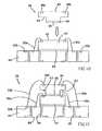
- FIG. 3shows a prior art three-die stack BGA package 10 b in which the first bottom die 12 b is mounted to a substrate 16 b by an adhesive element 14 b , a second (middle) die 18 b is mounted on the active surface 22 b of the bottom die 12 b by a second adhesive element 20 b , and a third (top) die 28 b is mounted on a spacer 30 b mounted on the active surface 32 b of the second (middle) die 18 b , with each of the dies being wire bonded 24 b to the substrate 16 b.
- a spacer 30 bis required to create the minimal clearance for the wire loop height between the second (middle) die 18 b and the third (top) die 28 b .
- the present inventionprovides semiconductor devices and stacked die assemblies, methods of fabricating the devices and assemblies for increasing semiconductor device density, and method of fabricating die packages of the assemblies.
- the inventionprovides a stacked die assembly.
- the stacked die assemblycomprises a first (bottom) die disposed on a substrate, a bonding element connecting bond pads on an active surface of the bottom die to terminal pads on the substrate, and a second die mounted on the bottom die.
- the second diehas a bottom surface with a recessed edge along the perimeter of the die that provides an opening for the bonding element extending from the bond pads of the bottom die, thus eliminating the need for a spacer between the two dies to achieve sufficient clearance for the bonding element.
- a second bonding elementconnects the bond pads on the active surface of the second die to terminal pads on the substrate. Adhesive elements are typically disposed between the two dies and the bottom die and the substrate.
- the stacked die assemblycomprises a first (bottom) die disposed on a substrate, typically through a flip chip attachment, and having a recess formed in the upper (inactive) surface.
- a second dieis at least partially disposed within the recess of the first die.
- a bonding elementconnects bond pads on the active surface of the second die to terminal pads on the substrate.
- An adhesive elementcan be disposed within the recess to attach the two dies.
- a third dieis mounted on the second die.
- the third diehas a bottom surface with a recessed edge along the perimeter of the die that provides an opening for the bonding element extending from the bond pads of the second die, thus eliminating the need for a spacer between the two dies for clearance of the bonding element.
- a second bonding elementconnects the bond pads on the active surface of the third die to terminal pads on the substrate.
- An adhesive elementcan be used to attach the second and third dies.
- the stacked die assemblycomprises a first (bottom) die disposed on a substrate, a bonding element connecting bond pads on the active surface of the first die to terminal pads on the substrate, and a second die mounted on the bottom die.
- a recessis formed on the bottom surface of the first die, and an adhesive element is disposed within the recess to attach to the first die to the substrate.
- the containment of the adhesive element in the recessrather than being disposed between the die and the substrate as a separate layer decreases the overall height of the die assembly.
- the second diehas a recessed edge along the perimeter of the bottom surface for clearance of the bonding element extending from the bond pads of the second die, thus eliminating the need for a spacer between the two dies. Bond pads on the second die are connected to terminal pads on the substrate by a second bonding element, and an adhesive element can be used to attach the second and third dies.
- the stacked die assemblycomprises a first (bottom) die disposed on a substrate, typically through a flip chip attachment, and a second die having a recess formed in the bottom (inactive) surface.
- the first dieis at least partially disposed in the recess of the second die, and a bonding element connects bonding pads on the second die.
- An adhesive elementcan be disposed within the recess to attach the two dies.
- the inventionprovides a semiconductor package.
- the packagecomprises a stacked die assembly according to the invention, at least partially encapsulated.
- the packagecan further include external contacts disposed on the second surface of the substrate for attaching the package as a component to an external electrical apparatus or device.
- the inventionprovides methods of fabricating the foregoing stacked die assemblies and semiconductor packages.
- FIGS. 1-3depict cross-sectional, side elevational views of prior art embodiments of stacked die packages.
- FIG. 4is a cross-sectional, side elevational view of an embodiment of a stacked die package according to the invention.
- FIG. 5is an enlarged partial view of the package of FIG. 4 , showing the recessed edge and opening between the stacked dies.
- FIGS. 6-11illustrate sequential processing steps in the fabrication of the stacked die package of FIG. 4 , according to an embodiment of a method of invention.
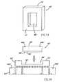
- FIG. 6is a bottom, perspective view of the second die of the package of FIG. 4 , showing the removed (etched) portion of the die forming the recessed edge along the perimeter of the die.
- FIGS. 7 and 9 - 11are cross-sectional, side elevational views of sequential steps in the mounting of the dies.
- FIG. 8is a top plan view of a panel with multiple die packages disposed thereon.
- FIG. 12is a cross-sectional, side elevational view of another embodiment of a stacked die package according to the invention.
- FIGS. 13-16illustrate sequential processing steps in the fabrication of the stacked die package of FIG. 12 , according to an embodiment of a method of invention.
- FIG. 14is a top, perspective view of the first (bottom) die of the package of FIG. 12 , showing the recess formed in the die.
- FIGS. 13 and 15 - 16are cross-sectional, side elevational views of sequential steps in the mounting of the dies.
- FIG. 17is a cross-sectional, side elevational view of another embodiment of a stacked die package according to the invention.
- FIGS. 18-19illustrate sequential processing steps in the fabrication of a portion of the stacked die package of FIG. 17 , according to an embodiment of a method of invention, showing the mounting of the third (top) die.
- FIG. 20is a cross-sectional, side elevational view of another embodiment of a stacked die package according to the invention.
- FIGS. 21-24illustrate sequential processing steps in the fabrication of the stacked die package of FIG. 20 , according to an embodiment of a method of invention.
- FIG. 22is a bottom, perspective view of the first (bottom) die of the package of FIG. 20 , showing the recess formed in the bottom surface of the die.
- FIGS. 21 , 23 , and 24are cross-sectional, side elevational views of sequential steps in the mounting of the dies.
- FIG. 25is a cross-sectional, side elevational view of another embodiment of a stacked die package according to the invention.
- FIGS. 26-29illustrate sequential processing steps in the fabrication of the stacked die package of FIG. 25 , according to an embodiment of a method of invention.
- FIG. 26is a bottom, perspective view of the second (top) die of the package of FIG. 25 , showing the recess formed in the bottom surface of the die.
- FIGS. 27-29are cross-sectional, side elevational views of sequential steps in the mounting of the dies.
- top and bottomand “upper” and “lower” are used herein for convenience and illustrative purposes only, and are not meant to limit the description of the invention inasmuch as the referenced item can be exchanged in position.
- the inventionadvantageously reduces the overall height of stacked die packages, achieves a desirably low package profile, allows the use of thicker dies in the stack assembly to reduce the number of cracked dies, eliminate the need for a spacer between dies to provide clearance for bond wires extending from an underlying die, and reduces the number of passes required for manufacturing multiple stacked dies by eliminating the need for mounting a spacer.
- the inventionfurther offers more reliable adhesion bleed out control, and the benefits increase as more dies are stacked.
- the method of the inventioncan be utilized to fabricate an assembly comprising additional stacked die layers to those of the illustrated embodiments using the described concepts herein.
- the backside (inactive surface) of a diecan be backgrinded or otherwise processed to a desired thickness, flatness value and texture using conventional methods in the art.
- a first embodiment of a multiple chip die assembly package 40is depicted in a cross-sectional, side elevational view.
- the package 40comprises a first (bottom) die 42 mounted to a support substrate 44 , and a second (top) die 46 mounted on the bottom die 42 .
- Bond pads 48 a , 48 b on the first and second dies 42 , 44are wire bonded 50 a , 50 b , respectively, to terminal pads 52 a , 52 b on the support substrate 44 .
- Substrate 44further includes external contacts 54 , for example, in the form of conductive solder balls, to connect the die package 40 to an external electrical apparatus (not shown). As best seen in FIG.
- a portion or thickness 60 (shown in phantom) along the perimeter 56 of the second (inactive) surface 58 of the second (top) die 46is removed (e.g., etched) to provide a recess (recessed edge) 62 .
- the recessed edge 62has a height (h) and provides an opening 63 for sufficient clearance of the bond wires 50 a (or other connecting member such as TAB tape) extending from the bond pads 48 a on the bottom die 42 to the substrate 44 . This eliminates the need for a spacer (e.g., FIG.
- Adhesive elements 64 , 66can be utilized, respectively, to secure the bottom die 42 onto the support substrate 44 , and the second (top) die 46 onto the bottom die 42 .
- FIGS. 6-11illustrate an embodiment of a process flow and method for forming the stacked die package 40 of FIG. 4 .
- a portion or thickness of the second (inactive) surface 58 of the second (top) die 46can be removed to form the recessed edge 62 .
- a portion 60 (shown in phantom in FIG. 5 ) of the surface 58has been removed along the perimeter 56 of the die.
- Known methods in the artcan be used to selectively remove a portion 60 along the perimeter of the die 46 such that when the die 46 is subsequently mounted onto the first (bottom) die 42 , the recessed edge 62 provides an opening with sufficient clearance for the bond wires 50 a extending from the bottom die 42 to the support substrate 44 .
- the recessed edge 62can be formed using known techniques in the art, for example, a chemical wet etch or dry etch, laser ablation, or other mechanical means of reducing the bottom surface 58 of the top die 46 to a predetermined depth.
- the first (bottom) die 42is mounted on a first surface 68 of the support substrate 44 .
- the bottom die 42comprises a first (active) surface 70 with a plurality of bond pads 48 a along the periphery thereof, and a second (bottom) surface 72 .
- the bottom surface 72 of the bottom die 42is aligned with and facing the first surface 68 of the support substrate 44 prior to assembly.
- the support substrate 44can comprise an electrically insulating polymer material such as a resin reinforced with glass fibers, for example, bismaleimide triazine (BT) resin, epoxy resins such as FR-4 or FR-5 laminates, ceramics, and polyimide resins; a metal leadframe (e.g., Alloy42 or copper); a flexible polyimide film (e.g., KAPTON® from DuPont, Wilmington, Del., or UPILEX® from Ube Industries, Ltd., Japan); among other substrates.
- a representative thickness of the substrateis about 50 ⁇ m to about 500 ⁇ m.
- the support substrate 44can be in the form of a strip or panel 74 on which multiple die packages 40 are formed, whereby the panel 74 can be singulated, for example, by cutting or shearing along an expansion slot 76 , into individual packages.
- the bottom die 42can be attached to the support substrate 44 by use of an adhesive element 64 .
- the adhesive element 64can be applied onto the bottom surface 72 of the bottom die 42 (as shown), and/or to the first surface 68 of the support substrate 44 .
- the adhesive element 64can comprise any suitable adhesive material known in the art, including contact adhesives, thermoplastic adhesives and thermosetting adhesives, for example, a die-attach epoxy or equivalent, or a double-sided, multi-layered adhesive tape such as polyimide film coated on both sides with adhesive.
- the bottom die 42 and/or the support substrate 44can be provided in a pre-taped form with an adhesive tape attached thereto, or an adhesive element 64 can be applied to either or both of the bottom die 42 and the support substrate 44 during fabrication of a stacked die package.
- adhesive application methods for liquid or gel adhesive applicationare known in the art, such as screen printing, roller applicator, spray, and transfer.
- an adhesive tapemay be applied from a dispenser and severed from a roll of tape, or applied from a transfer (carrier) film.
- the bond pads 48 a of the first (bottom) die 42are then electrically connected to the terminal pads 52 a on the support substrate 44 , for example, by wire bonding (as shown) or by tape automated bonding (“TAB”).
- wire bondingas shown
- TABtape automated bonding
- ball bonds(not shown) can be thermosonically bonded to the bond pads 48 a , and the bond wires 50 a extended and bonded to the terminal pads 52 a on the support substrate 44 .
- TAB bonding and ultrasonic bondingas known in the art, can be used to connect the bond pads 48 a and the terminal pads 52 a.
- the second (top) die 46is then mounted onto the first (active) surface 70 of the first (bottom) die 42 to form the stacked die assembly 78 .
- the second die 46comprises a first (active) surface 80 with a plurality of bond pads 48 b along the periphery thereof, and a second (inactive) surface 58 .
- the second surface 58 of the second (top) die 46is aligned with and facing the first surface 70 of the first (bottom) die 42 prior to assembly.
- the recessed edge 62 between the first (bottom) die 42 and the overlying second die 46is sized with a height (h) to provide an opening 63 for sufficient clearance of the bond wires 50 a extending from the bottom die 42 to the support substrate 44 .
- the second (top) die 46can be attached to the bottom die 42 by means of an adhesive element 66 , for example, a tape or die-attach adhesive as described with reference to adhesive element 64 .
- the first (bottom) die 42 and/or the second (top) die 46can be provided in a pre-taped form with an adhesive tape attached thereto, or an adhesive element 66 can be applied to either or both dies during mounting of the second (top) die onto the first (bottom) die.
- the bond pads 48 b of the second (top) die 46are then electrically connected to the terminal pads 52 b on the support substrate 44 , for example, by wire bonding, as shown in the illustrated example, or by TAB bonding, resulting in the wire-bonded stacked die assembly 78 .
- the die assembly 78can be partially or fully encapsulated with a dielectric encapsulation material 82 , typically a thermoset resin, the assembly 78 can be encapsulated using known techniques in the art, for example, screen printing, glob-top, pot molding, and transfer molding, resulting in the encapsulated stacked die package 40 depicted in FIG. 4 .
- a number of die assemblies 78can be placed in a lower mold plate or half of an open multi-cavity mold, one assembly within each cavity, and following encapsulation, the mold plates are separated and the individual packages 40 can be singulated.
- external contacts 54typically in the form of conductive solder balls (or other suitable conductive material such as conductive epoxies or conductor-filled epoxies), columns, pins, and the like, are mounted on the second (bottom) surface 84 of the support substrate 44 for electrical connection of the encased die package 40 as a component to an external electrical apparatus (not shown).
- Examples of such electric apparatusinclude a PCB or other external circuitry (not shown) such as a motherboard of a computer, program logic controller (PLC), a testing apparatus, among others.
- the support substrate 44typically includes a variety of conductive through-holes or vias 86 that extend through the cross-section of the substrate and establish routing of the conductive elements through the substrate 44 , and further include electrically conductive metal lines or traces and pads formed on the second (bottom) surface 84 on which the external contacts 54 are mounted.
- the panelcan be singulated into individual die packages 40 , for example, by cutting or shearing.
- the package 40 ′comprises a first (bottom) die 42 ′ mounted to a support substrate 44 ′ in a flip chip attachment, and a second (top) die 46 ′ mounted in a recess 88 ′ formed in the first (upper) surface 72 ′ of the bottom die 42 ′. Bond pads 48 b ′ on the second (top) die 46 ′ are wire bonded 50 b ′ to terminal pads 52 b ′ on the support substrate 44 ′.
- the substratefurther includes external contacts 54 ′ (e.g. solder balls) for connection of the die package 40 ′ as a component to an external electrical apparatus (not shown).
- the recess 88 ′ in the bottom die 42 ′allows the second (top) die 46 ′ to be inset into the bottom die 42 ′, thus achieving a lower overall package height 67 ′.
- An adhesive element 66 ′can be utilized to attach the second (top) die 46 ′ onto the bottom die 42 ′.
- FIGS. 13-16illustrate an embodiment of a process flow and method for forming the stacked die package 40 ′ of FIG. 12 .
- FIGS. 13 and 15depict simplified cross-sectional views of the mounting and bonding of the first (bottom) die 42 ′ in a flip chip attachment to the substrate 44 ′.
- the first die 42 ′comprises a first (active) surface 70 ′ and a second (inactive) surface 72 ′.
- the active surface 70 ′ of the first die 42 ′includes a plurality of bond pads with conductive bumps 90 ′ mounted thereon, which are arranged in a predetermined configuration.
- the conductive bumps 90 ′typically comprise a metal or alloy such as copper, silver or gold, or a conductive polymer material, and can be formed by known methods in the art, for example, electroplating, metal stud bumping by wire bonders, and stenciling.
- the support substrate 44 ′can be in a form as described, for example, with respect to the support substrate 44 (die package 40 ) ( FIGS. 6-11 ).
- a recess 88 ′can be formed in the second (inactive) surface 72 ′ of the first (bottom) die 42 ′, as shown in cross-section in FIG. 13 , and in a top perspective view in FIG. 14 .
- the recess 88 ′is sized and configured to receive the second die 46 ′ therein in a subsequent step.
- the recess 88 ′can be formed in any suitable shape, such as square, rectangular, oval, and circular.
- the recess 88 ′can be formed to a predetermined depth and width to accommodate the placement of the second die therein using known methods in the art, for example, patterning and utilizing a chemical wet etch or dry etch, laser ablation, or other mechanical means of removing the second (inactive) surface 72 ′ of the die. Dry etchers are commercially available, for example, from Secon Semiconductor Equipment GmbH, ⁇ eck, Austria, having an etch rate of 25 ⁇ m/min. for an 8-inch wafer.
- the recesscan be formed at the wafer level, the die level (i.e., singulated die), or on a strip level after the die 42 ′ is mounted on the substrate (e.g., strip).
- the bottom die 42 ′can be mounted on the support substrate 44 ′ by conventional flip chip methodology. As shown in FIG. 13 , the active surface 70 ′ of the bottom die 42 ′ is aligned with and facing the first (upper) surface 68 ′ of the support substrate 44 ′ prior to assembly. Traces and electrical connections (not shown) on the first surface 68 ′ of the support substrate 44 ′ are configured to correspond to the configuration of bond pads and the conductive bumps 90 ′ of the bottom die 42 ′.
- the conductive bumps 90 ′ in the form of solder bumpscan be reflowed to physically and electrically bond with the traces or other conductive elements on the first (upper) surface 68 ′ of the support substrate 44 ′, or cured in the case of conductive polymer bumps, although other methods such as thermal compression can also be used.
- Terminal pads 52 b ′ on the first surface 68 ′ of the support substrate 44 ′are exposed along the periphery.
- the second (top) die 46 ′is then mounted in the recess 88 ′ of the bottom die 42 ′.
- the second (top) die 46 ′comprises a first (active) surface 80 ′ with a plurality of bond pads 48 b ′ along the periphery thereof, and a second (bottom) surface 58 ′.
- the second (bottom) surface 58 ′ of the second (top) die 46 ′is aligned with and facing the recess 88 ′ in the second surface 72 ′ of the bottom die 42 ′ prior to assembly.
- the second (top) die 46 ′can be attached to the bottom die 42 ′ by means of an adhesive element 66 ′.
- the adhesive element 66 ′can be applied within the recess 88 ′ to the recess surface 92 ′ of the bottom die 42 ′, and/or to the second surface 58 ′ of the top die 46 ′ (as shown).
- the adhesive element 66 ′can comprise any suitable adhesive material known in the art, for example, a tape adhesive or die attach adhesive, as described with respect to adhesive element 64 ′.
- the adhesive element 66 ′can have a thickness such that it functions as a spacer to control the degree of insertion of the second die 46 ′ into the recess 88 ′.
- the first and/or second dies 42 ′, 46 ′can be provided in a pre-taped form with an adhesive tape attached thereto, or an adhesive element 66 ′ can be applied to either or both dies during fabrication of the stacked die package 40 ′.
- the adhesive element 66 ′can be applied by conventional methods known in the art.
- the bond pads 48 b ′ of the second (top) die 46 ′are then electrically connected by wire bonds 50 b ′ to the terminal pads 52 b ′ on the support substrate 44 ′, for example, by wire bonding (as shown) or by TAB bonding.
- the wire bonded stacked die assembly 78 ′can then be partially or fully encapsulated with a dielectric encapsulation material 82 ′ using known methods in the art to form the encapsulated stacked die package 40 ′ shown in FIG. 12 .
- External contacts 54 ′e.g., conductive solder balls can then be mounted on the second (bottom) surface 84 ′ of the support substrate 44 ′ for connecting the die package 40 ′ to a motherboard or other electrical apparatus (not shown).
- a panel substrate comprising a plurality of dies(e.g., FIG. 8 , panel 74 ) can then be singulated into individual die packages 40 ′.
- a further embodiment of a multiple chip die assembly package according to the inventionis depicted in a cross-sectional, side elevational view in FIG. 17 .
- the die package 40 ′′incorporates features of the die packages 40 , 40 ′ depicted in FIGS. 4 and 12 .
- the package 40 ′′comprises a first (bottom) die 42 ′′ mounted onto a support substrate 44 ′′ in a flip chip attachment, and a second (middle) die 46 ′′ at least partially received within a recess 88 ′′ in the bottom die 42 ′′, similar to the die package 40 ′ ( FIG. 12 ).
- the package 40 ′′further comprises a third (top) die 94 ′′ mounted on the first (active) surface 80 ′′ of the second (middle) die 46 ′′, similar to the die package 40 ( FIG. 4 ).
- Bond pads 48 b ′′, 48 c ′′ on the second (middle) die 46 ′′ and the third (top) die 94 ′′are wire bonded ( 50 B′′, 50 c ′′) to terminal pads 52 b ′′, 52 c ′′, respectively, on the support substrate 44 ′′.
- Substrate 44 ′′further includes external contacts 54 ′′ (e.g., solder balls) for connecting the die package 40 ′′ as a component to an electrical apparatus (not shown).
- a portion along the perimeter of the second (inactive) surface 96 ′′ of the third (top) die 94 ′′is partially removed to provide a recessed edge 62 ′′ to provide an opening 63 ′′ for sufficient clearance of the bond wires 50 b ′′ connecting the bond pads 48 b ′′ on the second (middle) die 46 ′′ to the substrate 44 ′′, thus eliminating the need for a spacer between the two dies 46 ′′, 94 ′′.
- the recess 88 ′′ in the bottom die 42 ′′allows the second (middle) die 46 ′′ to be inserted (nested) therein.
- the recess features 62 ′′, 88 ′′advantageously combine to achieve a lower overall package height 67 ′′.
- Adhesive members 66 ′′, 98 ′′can be utilized, respectively, to attach the second (middle) die 46 ′′ to the bottom die 42 ′′, and the third (top) die 94 ′′ to the second (middle) die 46 ′′.
- the stacked die package 40 ′′ of FIG. 17can be fabricated utilizing the process steps described above in fabricating packages 40 , 40 ′.
- the recesses 88 ′′, 62 ′′can be formed in the first (bottom) die 42 ′′ and the third (top) die 94 ′′, respectively.
- a recess 88 ′′can be formed in the second (inactive) surface 72 ′′ of the bottom die 42 ′′ ( FIG. 18 ), as described with respect to die 42 ′ (package 40 ) and as depicted in FIGS. 13-14 .
- the recess 88 ′′is sized and configured to receive the second (middle) die 46 ′′ therein in a subsequent step, and can be suitably shaped to correspond with the shape of the second die.
- a recessed edge 62 ′′ along the perimeter 56 ′′ of the second (inactive) surface 58 ′′ of the third (top) die 94 ′′can be formed as described previously for the second die 46 of package 40 and as depicted in FIGS. 4-6 .
- a portion 60 ′′ of the third (top) die 94 ′′is removed along the second (bottom) surface 58 ′′ to provide a recessed edge 62 ′′.
- the first (bottom) die 42 ′′is mounted on a support substrate 44 ′′ using flip chip technology, with the terminal pads 52 a ′′, 52 b ′′ on the surface of the support substrate 44 ′′ exposed along the periphery.
- the second (middle) die 46 ′′is then mounted in the recess 88 ′′ of the bottom die 42 ′′, as depicted in FIGS. 15-16 .
- the second die 46 ′′comprises a plurality of bond pads 48 b ′′ on a first (active) surface 80 ′′, and a second (bottom) surface 58 ′′.
- the bottom surface 58 ′′ of the second die 46 ′′is mounted onto the recess surface 92 ′′ of the bottom die 42 ′′ by means of an adhesive element 66 ′′, such as a tape or die-attach adhesive as described with respective to adhesive element 64 .
- the dies 42 ′′, 46 ′′can be pre-taped or an adhesive element 66 ′′ can be applied to the surface of either or both dies during fabrication of the package.
- the bond pads 48 b ′′ of the second die 46 ′′are then electrically connected to the terminal pads 52 b ′′ on the support substrate 44 ′′, for example, by wire bonding or by TAB binding, resulting in a structure similar to that shown in FIG. 16 .
- the third (top) die 94 ′′can then be mounted on the second (middle) die 46 ′′ similar to the mounting of the second die 46 on the bottom die 42 shown in FIGS. 10-11 .
- the third (top) die 94 ′′is mounted onto the first (active) surface 80 ′′ of the second die 46 ′′ to form the stacked die assembly 78 ′′, as depicted in FIG. 19 .
- the third (top) die 94 ′′comprises a first (active) surface 100 ′′ with a plurality of bond pads 48 c ′′ along the periphery thereof, and a second surface 96 ′′ with recessed edge 62 ′′.
- the second surface 96 ′′ of the third (top) die 94 ′′is aligned with and facing the first (active) surface 80 ′′ of the second (middle) die 46 ′′ prior to assembly.
- the third (top) die 100 ′′can be attached to the second die 46 ′′ by means of an adhesive element 98 ′′, for example, a tape or die attach adhesive, as described hereinabove with respect to adhesive element 64 .
- the dies 46 ′′, 100 ′′can be provided in a pre-taped form or an adhesive element 98 ′′ can be applied to either or both dies during mounting of the third die 94 ′′ onto the second die 46 ′′.
- the recessed edge 62 ′′ of the third (top) die 94 ′′has a height (h′′) to provide an opening 63 ′′′ with sufficient clearance for the bond wires 50 b ′′ extending from the second die 46 ′′ to the support substrate 44 ′′.
- the bond pads 48 c ′′ of the third (top) die 94 ′′are then electrically connected to the terminal pads 52 c ′′ on the support substrate 44 ′′, for example, by wire bonding ( 50 c ′′) or TAB bonding.
- the die assembly 78 ′′can be partially or fully encapsulated 82 ′′ resulting in the die package 40 ′′ depicted in FIG. 17 .
- External contacts 54 ′′ in the form of conductive solder balls (or other suitable conductive material or form)are mounted on the second (bottom) surface 84 ′′ of the support substrate 44 ′′ to provide electrical connection of the die package 40 ′′ to an electrical apparatus (not shown). Thereafter, a multi-die panel can be singulated into individual die packages.
- FIG. 20another embodiment of a multiple chip die assembly package according to the invention is depicted in a cross-sectional, side elevational view.
- the package 40 ′′′comprises a first (bottom) die 42 ′′′ mounted to a support substrate 44 ′′′, and a second (top) die 46 ′′′ mounted on the bottom die 42 ′′′.
- the second die 46 ′′′comprises a first (active) surface 80 ′′′ with bond pads 48 b ′′′ along the periphery thereof, and a second (inactive) surface 58 ′′′.
- the second die 46 ′′′is larger in size, i.e., a greater width (w) and/or length (l) than the bottom die (see FIG. 6 ).
- Bond pads 48 a ′′′, 48 b ′′′, on the first and second dies 42 ′′′, 46 ′′′are wire bonded 50 a ′′′, 50 b ′′′ to terminal pads 52 a ′′′, 52 b ′′′ on the support substrate 44 ′′′, which further includes external contacts 54 ′′′ to connect the die package 40 ′′′ to an electrical apparatus. Similar to the die 46 depicted and described with respect to FIGS. 4-6 , a portion of the second (inactive) surface 58 ′′′ of the second (top) die 46 ′′′ is removed to provide a recessed edge 62 ′′′ for sufficient clearance for the bond wires 50 a ′′′ mounted on the underlying bottom die 42 ′′′.
- a cavity or recess 102 ′′′is also etched in the second (bottom) surface 72 ′′′ of the bottom die 42 ′′′, and is sized for receiving an adhesive element 104 ′′′ therein to secure the bottom die 42 ′′′ to the support substrate 44 ′′′.
- the recess features 62 ′′′, 102 ′′′combine to achieve a lower overall package height 67 ′′′ for the package 40 ′′′ by eliminating the need for a spacer between the top and bottom dies, and mounting the adhesive element 104 ′′′ as an insert into the recess 102 ′′′ in the bottom die 42 ′′′ rather than as a distinct layer between the bottom die 42 ′′′ and the substrate 44 ′′′.
- the recess 102 ′′′contains a die-attach adhesive therein and limits the amount of adhesive (epoxy) bleed onto bond fingers and/or other components on the substrate adjacent to the die edge.
- FIGS. 21-24illustrate an embodiment of a method and process flow for forming the stacked die package of FIG. 20 .
- the recesses 102 ′′′, 62 ′′′can be formed in the first (bottom) die 42 ′′′ and the second (top) die 46 ′′′, respectively.
- a recess 102 ′′′is formed in the second (bottom) surface 72 ′′′ of the first (bottom) die 42 ′′′.
- the recess 102 ′′′is sized and configured to receive an adhesive member 104 ′′′ therein for attachment of the die 42 ′′′ to the substrate 44 ′′′.
- the recess 102 ′′′can be formed in any suitable shape, such as square, rectangular, oval, and circular.
- the recess 102 ′′′can be formed using known methods in the art, for example, patterning and utilizing a chemical wet etch or dry etch, mechanical drilling or punching, and laser ablation of the second surface 72 ′′′ of the die 42 ′′′.
- the recess 102 ′′′can be formed at the wafer level or the die level (i.e., singulated die).
- a recessed edge 62 ′′′ along the perimeter 56 ′′′ of the second (inactive) surface 58 ′′′ of the second (top) die 46 ′′′can be formed as described previously for the second die 46 (package 40 ) depicted in FIGS. 4-6 .
- a portion of the die 46 ′′′is removed such that, when the second die 46 ′′′ is then mounted onto the first die 42 ′′′, the recessed edge 62 ′′′ provides an opening 63 ′′′ for sufficient clearance of the bond wires 50 a ′′′ extending from the first die 42 ′′′ to the terminal pads 52 a ′′′ on the support substrate 44 ′′′.
- the second (bottom) surface 71 ′′′ of the first (bottom) die 42 ′′′is aligned with and facing the first (upper) surface 68 ′′′ of the support substrate 44 ′′′ prior to assembly.
- the first die 42 ′′′is attached to the support substrate 44 ′′′ by means of an adhesive element 104 ′′′.
- the adhesive element 104 ′′′can be applied to the recess surface 106 ′′′ of the recess 102 ′′′ of the first (bottom) die 42 ′′′, and/or onto the first (upper) surface 68 ′′′ of the substrate 44 ′′′ and aligned with the recess 102 ′′′ to be received therein.
- the adhesive element 104 ′′′can comprise an adhesive gel or tape, as described hereinabove with respect to adhesive element 64 (package 40 ).
- the first die 44 ′′′ and/or the substrate 44 ′′′can be provided in a pre-taped form, or an adhesive element 104 ′′′ can be applied to the surface of either or both the first die 42 ′′′ and the substrate 44 ′′′ during the attachment step.
- the first die 42 ′′′is attached to the substrate 44 ′′′ such that the terminal pads 52 a ′′′, 52 b ′′′ on the surface of the substrate are exposed.
- the second (top) die 46 ′′′is then mounted onto the first (bottom) die 42 ′′′ to form the stacked die assembly 78 ′′′.
- the second surface 58 ′′′ of the second (top) die 46 ′′′is aligned with and facing the first (active) surface 70 ′′′ of the first (bottom) die 42 ′′′ prior to assembly.
- the second (top) die 46 ′′′can be attached to the first die by means of an adhesive element 66 ′′′, for example, with a tape or die attach adhesive, as described with respect to the adhesive element 64 (die package 40 ).
- Either or both of the first and second dies 42 ′′′, 46 ′′′can be provided in a pre-taped form or the adhesive element 66 ′′′ can applied to either or both dies during the mounting step.
- the bond pads 48 b ′′′ of the second (top) die 46 ′′′can then be electrically connected to the terminal pads 52 b ′′′ on the substrate 44 ′′′.
- the recessed edge 62 ′′′ of the second (top) die 46 ′′′has a height (h′′′) sufficient to provide an opening 63 ′′′ for adequate clearance of the bonding wires 50 a ′′′ extending from the second die 46 ′′′ to the substrate 44 ′′′.
- the wire-bonded stacked die assembly 78 ′′′can be partially or fully encapsulated with an encapsulant material 82 ′′′ using known techniques in the art to form the encapsulated stacked die package 40 ′′′ as depicted in FIG. 20 . Thereafter, external contacts 54 ′′′ can be mounted on the second (bottom) surface 84 ′′′ of the support substrate 44 ′′′ for electrical connection of the die package 40 ′′′ to an external electrical apparatus (not shown).
- Singulation of a multiple die panel or stripcan then be performed to provide individual die packages 40 ′′′.
- the package 40 ′′′′comprises a first (bottom) die 42 ′′′′ mounted in a flip chip attachment to a support substrate 44 ′′′′, and a larger sized, second (top) die 46 ′′′′ mounted on the first (bottom) die 42 ′′′′.
- Bond pads 48 b ′′′′ on the second (top) die 46 ′′′′are wire bonded 50 b ′′′′ to terminal pads 52 b ′′′′ on the support substrate 44 ′′′′.
- External contacts 54 ′′′′are mounted on the second (bottom) surface of the substrate 44 ′′′′ for connecting the package 40 ′′′′ to an external electrical apparatus (not shown).
- a portion of the second (bottom) surface 58 ′′′′ of the second (top) die 46 ′′′′is removed to provide a recess 108 ′′′′ for receiving the bottom die 42 ′′′′ therein.
- the recess feature 108 ′′′′helps achieve a lower overall package height 67 ′′′′ for the package 40 ′′′′ by nesting the first die 42 ′′′′ within the overlying second die 46 ′′′′.
- FIGS. 26-29illustrate an embodiment of a method and process flow for forming the stacked die package of FIG. 25 .
- the recess 108 ′′′′can be formed in the second (bottom) surface 58 ′′′′ of the second (top) die 46 ′′′′, as shown in FIG. 25 and in a bottom perspective view in FIG. 26 .
- the recess 108 ′′′′can be formed at the wafer level or the die level.
- the recess 108 ′′′′is sized and configured to receive the bottom die 42 ′′′′ therein, and can be formed in any suitable shape, such as square, rectangular, oval, and circular using known techniques in the art.
- the first (active) surface 70 ′′′′ of the first (bottom) die 42 ′′′′is aligned with and facing the first (upper) surface 68 ′′′′ of the support substrate 44 ′′′′ prior to assembly.
- the active surface 70 ′′′′ of the first die 42 ′′′′includes a plurality of bond pads with conductive bumps 90 ′′′′ mounted thereon, which are arranged in a predetermined configuration.
- the bottom die 42 ′′′′can be mounted on the support substrate 44 ′′′′ according to conventional flip chip techniques, resulting in the structure shown in FIG. 28 .
- the second (top) die 46 ′′′′is then mounted onto the first (bottom) die 42 ′′′′ to form the stacked die assembly 78 ′′′′.
- the second die 46 ′′′′comprises a first (active) surface 80 ′′′′ with bond pads 48 b ′′′′, and a second (inactive) surface 58 ′′′′.
- the second surface 58 ′′′′ of the second (top) die 46 ′′′′is aligned with and facing the second surface 72 ′′′′ of the first (bottom) die 42 ′′′′ prior to assembly.
- the first (bottom) die 42 ′′′′is received at least partially in the recess 108 ′′′′ and can be attached to the recess surface 106 ′′′′ of the second die 46 ′′′′ by means of an adhesive element 66 ′′′′ such as a tape or die attach adhesive as described with respect to the adhesive element 64 (die package 40 ).
- an adhesive element 66 ′′′′such as a tape or die attach adhesive as described with respect to the adhesive element 64 (die package 40 ).
- Either or both of the first and second dies 42 ′′′′, 46 ′′′′can be provided in a pre-taped form, or the adhesive element 66 ′′′′ can applied to either or both dies during the mounting step.
- the bond pads 48 b ′′′′ on the first (active) surface 80 ′′′′ of the second (top) die 46 ′′′′can then be electrically connected to the terminal pads 52 b ′′′′ on the substrate 44 ′′′′.
- Partial or full encapsulation of the die assembly 78 ′′′′can be performed using known techniques in the art to form the encapsulated package 40 ′′′′ shown in FIG. 25 .
- External contacts 54 ′′′′can then be mounted on the second (bottom) surface 84 ′′′′ of the substrate 44 ′′′′ to facilitate electrical connection of the component die package 40 ′′′′ to an external electrical apparatus (not shown).
- Individual die packages of a multiple die panelcan be separated by a singulation technique.
- FIG. 2FIG. 12 Bottom die, thickness 6 mils 6 mils Second die, thickness 6 mils 6 mils Bond line, thickness 1 mil 1 mil Slot (recess) depth — 4 mils Overall total thickness of the 13 mils 9 mils stacked dies
- a lower package heightcan be achieved using thicker dies.
- thicker diescan be utilized to help reduce the number of cracked dies that occur during the assembly process.
Landscapes
- Engineering & Computer Science (AREA)
- Microelectronics & Electronic Packaging (AREA)
- Power Engineering (AREA)
- Computer Hardware Design (AREA)
- Condensed Matter Physics & Semiconductors (AREA)
- General Physics & Mathematics (AREA)
- Physics & Mathematics (AREA)
- Manufacturing & Machinery (AREA)
- Die Bonding (AREA)
- Wire Bonding (AREA)
- Encapsulation Of And Coatings For Semiconductor Or Solid State Devices (AREA)
- Structures Or Materials For Encapsulating Or Coating Semiconductor Devices Or Solid State Devices (AREA)
- Lead Frames For Integrated Circuits (AREA)
Abstract
Description
| FIG. 2 | FIG. 12 | ||
| Bottom die, thickness | 6 mils | 6 mils | ||
| Second die, thickness | 6 mils | 6 mils | ||
| Bond line, thickness | 1 mil | 1 mil | ||
| Slot (recess) depth | — | 4 mils | ||
| Overall total thickness of the | 13 mils | 9 mils | ||
| stacked dies | ||||
Claims (7)
Priority Applications (2)
| Application Number | Priority Date | Filing Date | Title |
|---|---|---|---|
| US12/020,738US8373277B2 (en) | 2002-01-09 | 2008-01-28 | Stacked die in die BGA package |
| US13/765,077US20130154117A1 (en) | 2002-01-09 | 2013-02-12 | Stacked die in die bga package |
Applications Claiming Priority (5)
| Application Number | Priority Date | Filing Date | Title |
|---|---|---|---|
| SG200200134-5 | 2002-01-09 | ||
| SG200200134ASG121702A1 (en) | 2002-01-09 | 2002-01-09 | Stacked die in die bga package |
| US10/068,159US7332819B2 (en) | 2002-01-09 | 2002-02-05 | Stacked die in die BGA package |
| US10/424,470US7344969B2 (en) | 2002-01-09 | 2003-04-28 | Stacked die in die BGA package |
| US12/020,738US8373277B2 (en) | 2002-01-09 | 2008-01-28 | Stacked die in die BGA package |
Related Parent Applications (1)
| Application Number | Title | Priority Date | Filing Date |
|---|---|---|---|
| US10/424,470ContinuationUS7344969B2 (en) | 2002-01-09 | 2003-04-28 | Stacked die in die BGA package |
Related Child Applications (1)
| Application Number | Title | Priority Date | Filing Date |
|---|---|---|---|
| US13/765,077DivisionUS20130154117A1 (en) | 2002-01-09 | 2013-02-12 | Stacked die in die bga package |
Publications (2)
| Publication Number | Publication Date |
|---|---|
| US20080136045A1 US20080136045A1 (en) | 2008-06-12 |
| US8373277B2true US8373277B2 (en) | 2013-02-12 |
Family
ID=26665232
Family Applications (12)
| Application Number | Title | Priority Date | Filing Date |
|---|---|---|---|
| US10/068,159Expired - LifetimeUS7332819B2 (en) | 2001-12-12 | 2002-02-05 | Stacked die in die BGA package |
| US10/389,433Expired - Fee RelatedUS7371608B2 (en) | 2002-01-09 | 2003-03-14 | Method of fabricating a stacked die having a recess in a die BGA package |
| US10/424,426Expired - LifetimeUS7332820B2 (en) | 2002-01-09 | 2003-04-28 | Stacked die in die BGA package |
| US10/424,470Expired - Fee RelatedUS7344969B2 (en) | 2002-01-09 | 2003-04-28 | Stacked die in die BGA package |
| US11/440,913Expired - LifetimeUS7282390B2 (en) | 2002-01-09 | 2006-05-25 | Stacked die-in-die BGA package with die having a recess |
| US11/511,653Expired - LifetimeUS7309623B2 (en) | 2002-01-09 | 2006-08-29 | Method of fabricating a stacked die in die BGA package |
| US11/511,941Expired - Fee RelatedUS7358117B2 (en) | 2002-01-09 | 2006-08-29 | Stacked die in die BGA package |
| US11/511,956Expired - LifetimeUS7282392B2 (en) | 2002-01-09 | 2006-08-29 | Method of fabricating a stacked die in die BGA package |
| US11/872,489Expired - LifetimeUS7799610B2 (en) | 2002-01-09 | 2007-10-15 | Method of fabricating a stacked die having a recess in a die BGA package |
| US11/959,013Expired - LifetimeUS7575953B2 (en) | 2002-01-09 | 2007-12-18 | Stacked die with a recess in a die BGA package |
| US12/020,738Expired - Fee RelatedUS8373277B2 (en) | 2002-01-09 | 2008-01-28 | Stacked die in die BGA package |
| US13/765,077AbandonedUS20130154117A1 (en) | 2002-01-09 | 2013-02-12 | Stacked die in die bga package |
Family Applications Before (10)
| Application Number | Title | Priority Date | Filing Date |
|---|---|---|---|
| US10/068,159Expired - LifetimeUS7332819B2 (en) | 2001-12-12 | 2002-02-05 | Stacked die in die BGA package |
| US10/389,433Expired - Fee RelatedUS7371608B2 (en) | 2002-01-09 | 2003-03-14 | Method of fabricating a stacked die having a recess in a die BGA package |
| US10/424,426Expired - LifetimeUS7332820B2 (en) | 2002-01-09 | 2003-04-28 | Stacked die in die BGA package |
| US10/424,470Expired - Fee RelatedUS7344969B2 (en) | 2002-01-09 | 2003-04-28 | Stacked die in die BGA package |
| US11/440,913Expired - LifetimeUS7282390B2 (en) | 2002-01-09 | 2006-05-25 | Stacked die-in-die BGA package with die having a recess |
| US11/511,653Expired - LifetimeUS7309623B2 (en) | 2002-01-09 | 2006-08-29 | Method of fabricating a stacked die in die BGA package |
| US11/511,941Expired - Fee RelatedUS7358117B2 (en) | 2002-01-09 | 2006-08-29 | Stacked die in die BGA package |
| US11/511,956Expired - LifetimeUS7282392B2 (en) | 2002-01-09 | 2006-08-29 | Method of fabricating a stacked die in die BGA package |
| US11/872,489Expired - LifetimeUS7799610B2 (en) | 2002-01-09 | 2007-10-15 | Method of fabricating a stacked die having a recess in a die BGA package |
| US11/959,013Expired - LifetimeUS7575953B2 (en) | 2002-01-09 | 2007-12-18 | Stacked die with a recess in a die BGA package |
Family Applications After (1)
| Application Number | Title | Priority Date | Filing Date |
|---|---|---|---|
| US13/765,077AbandonedUS20130154117A1 (en) | 2002-01-09 | 2013-02-12 | Stacked die in die bga package |
Country Status (3)
| Country | Link |
|---|---|
| US (12) | US7332819B2 (en) |
| AU (1) | AU2003207484A1 (en) |
| WO (1) | WO2003061006A2 (en) |
Cited By (2)
| Publication number | Priority date | Publication date | Assignee | Title |
|---|---|---|---|---|
| US20120264258A1 (en)* | 2011-04-15 | 2012-10-18 | Freescale Semiconductor, Inc | Method of assembling semiconductor device including insulating substrate and heat sink |
| US20130221542A1 (en)* | 2012-02-24 | 2013-08-29 | Taiwan Semiconductor Manufacturing Company, Ltd. | Functional Spacer for SIP and Methods for Forming the Same |
Families Citing this family (200)
| Publication number | Priority date | Publication date | Assignee | Title |
|---|---|---|---|---|
| US6841412B1 (en)* | 1999-11-05 | 2005-01-11 | Texas Instruments Incorporated | Encapsulation for particle entrapment |
| US7064447B2 (en)* | 2001-08-10 | 2006-06-20 | Micron Technology, Inc. | Bond pad structure comprising multiple bond pads with metal overlap |
| US20030042615A1 (en) | 2001-08-30 | 2003-03-06 | Tongbi Jiang | Stacked microelectronic devices and methods of fabricating same |
| US7332819B2 (en)* | 2002-01-09 | 2008-02-19 | Micron Technology, Inc. | Stacked die in die BGA package |
| SG167661A1 (en)* | 2002-01-09 | 2011-01-28 | Micron Technology Inc | Stacked die in die bga package |
| US6896760B1 (en)* | 2002-01-16 | 2005-05-24 | Micron Technology, Inc. | Fabrication of stacked microelectronic devices |
| DE10209204B4 (en)* | 2002-03-04 | 2009-05-14 | Infineon Technologies Ag | Electronic component comprising a stack of semiconductor chips and method of making the same |
| US7323767B2 (en)* | 2002-04-25 | 2008-01-29 | Micron Technology, Inc. | Standoffs for centralizing internals in packaging process |
| US6809416B1 (en)* | 2002-05-28 | 2004-10-26 | Intersil Corporation | Package for integrated circuit with thermal vias and method thereof |
| US6927497B2 (en)* | 2002-08-22 | 2005-08-09 | Intel Corporation | Multi-die semiconductor package |
| US7034387B2 (en) | 2003-04-04 | 2006-04-25 | Chippac, Inc. | Semiconductor multipackage module including processor and memory package assemblies |
| AU2003298595A1 (en) | 2002-10-08 | 2004-05-04 | Chippac, Inc. | Semiconductor stacked multi-package module having inverted second package |
| KR100618812B1 (en)* | 2002-11-18 | 2006-09-05 | 삼성전자주식회사 | Stacked multi-chip package with improved reliability |
| KR20040086869A (en)* | 2003-03-22 | 2004-10-13 | 삼성전자주식회사 | Wafer dicing method for making the semiconductor chip having various shape |
| JP4705748B2 (en)* | 2003-05-30 | 2011-06-22 | ルネサスエレクトロニクス株式会社 | Manufacturing method of semiconductor device |
| US7042098B2 (en)* | 2003-07-07 | 2006-05-09 | Freescale Semiconductor,Inc | Bonding pad for a packaged integrated circuit |
| DE10339487B4 (en)* | 2003-08-27 | 2007-03-15 | Infineon Technologies Ag | Method for applying a semiconductor chip to a carrier |
| US7071421B2 (en) | 2003-08-29 | 2006-07-04 | Micron Technology, Inc. | Stacked microfeature devices and associated methods |
| JP4130167B2 (en)* | 2003-10-06 | 2008-08-06 | 日東電工株式会社 | Semiconductor wafer peeling method |
| EP1501126A1 (en)* | 2003-11-05 | 2005-01-26 | Infineon Technologies AG | Semiconductor chip having a cavity for stacked die application |
| US7091124B2 (en) | 2003-11-13 | 2006-08-15 | Micron Technology, Inc. | Methods for forming vias in microelectronic devices, and methods for packaging microelectronic devices |
| US8084866B2 (en) | 2003-12-10 | 2011-12-27 | Micron Technology, Inc. | Microelectronic devices and methods for filling vias in microelectronic devices |
| TWI278947B (en)* | 2004-01-13 | 2007-04-11 | Samsung Electronics Co Ltd | A multi-chip package, a semiconductor device used therein and manufacturing method thereof |
| TWI247371B (en)* | 2004-02-06 | 2006-01-11 | Advanced Semiconductor Eng | Semiconductor package and method for manufacturing the same |
| US20050194698A1 (en)* | 2004-03-03 | 2005-09-08 | St Assembly Test Service Ltd. | Integrated circuit package with keep-out zone overlapping undercut zone |
| US7145249B2 (en)* | 2004-03-29 | 2006-12-05 | Intel Corporation | Semiconducting device with folded interposer |
| US7378725B2 (en)* | 2004-03-31 | 2008-05-27 | Intel Corporation | Semiconducting device with stacked dice |
| JP2005308629A (en)* | 2004-04-23 | 2005-11-04 | Canon Inc | Mirror unit and manufacturing method thereof |
| US20050247894A1 (en)* | 2004-05-05 | 2005-11-10 | Watkins Charles M | Systems and methods for forming apertures in microfeature workpieces |
| DE102004025279B4 (en)* | 2004-05-19 | 2011-04-28 | Infineon Technologies Ag | System for equipping substrates with ball contacts and method for equipping substrates with ball contacts |
| US20050285254A1 (en)* | 2004-06-23 | 2005-12-29 | Buot Joan R V | Semiconducting device having stacked dice |
| US7232754B2 (en) | 2004-06-29 | 2007-06-19 | Micron Technology, Inc. | Microelectronic devices and methods for forming interconnects in microelectronic devices |
| US7242101B2 (en)* | 2004-07-19 | 2007-07-10 | St Assembly Test Services Ltd. | Integrated circuit die with pedestal |
| SG120200A1 (en) | 2004-08-27 | 2006-03-28 | Micron Technology Inc | Slanted vias for electrical circuits on circuit boards and other substrates |
| US7300857B2 (en) | 2004-09-02 | 2007-11-27 | Micron Technology, Inc. | Through-wafer interconnects for photoimager and memory wafers |
| US20060051912A1 (en)* | 2004-09-09 | 2006-03-09 | Ati Technologies Inc. | Method and apparatus for a stacked die configuration |
| JP4601365B2 (en)* | 2004-09-21 | 2010-12-22 | ルネサスエレクトロニクス株式会社 | Semiconductor device |
| US8324725B2 (en)* | 2004-09-27 | 2012-12-04 | Formfactor, Inc. | Stacked die module |
| TW200612345A (en)* | 2004-10-07 | 2006-04-16 | Advanced Flash Memory Card Technology Co Ltd | Structure of memory card and producing method thereof |
| US7816182B2 (en)* | 2004-11-30 | 2010-10-19 | Stmicroelectronics Asia Pacific Pte. Ltd. | Simplified multichip packaging and package design |
| TWI250629B (en)* | 2005-01-12 | 2006-03-01 | Ind Tech Res Inst | Electronic package and fabricating method thereof |
| US20070109756A1 (en)* | 2005-02-10 | 2007-05-17 | Stats Chippac Ltd. | Stacked integrated circuits package system |
| US7160798B2 (en)* | 2005-02-24 | 2007-01-09 | Freescale Semiconductor, Inc. | Method of making reinforced semiconductor package |
| KR100618892B1 (en)* | 2005-04-13 | 2006-09-01 | 삼성전자주식회사 | Semiconductor package achieves fan-out structure through wire bonding |
| US7795134B2 (en) | 2005-06-28 | 2010-09-14 | Micron Technology, Inc. | Conductive interconnect structures and formation methods using supercritical fluids |
| US20070026573A1 (en)* | 2005-07-28 | 2007-02-01 | Aminuddin Ismail | Method of making a stacked die package |
| US7622377B2 (en)* | 2005-09-01 | 2009-11-24 | Micron Technology, Inc. | Microfeature workpiece substrates having through-substrate vias, and associated methods of formation |
| US7863187B2 (en) | 2005-09-01 | 2011-01-04 | Micron Technology, Inc. | Microfeature workpieces and methods for forming interconnects in microfeature workpieces |
| US7262134B2 (en) | 2005-09-01 | 2007-08-28 | Micron Technology, Inc. | Microfeature workpieces and methods for forming interconnects in microfeature workpieces |
| US7605476B2 (en) | 2005-09-27 | 2009-10-20 | Stmicroelectronics S.R.L. | Stacked die semiconductor package |
| US20070111399A1 (en)* | 2005-11-14 | 2007-05-17 | Goida Thomas M | Method of fabricating an exposed die package |
| TW200723495A (en)* | 2005-12-07 | 2007-06-16 | Chipmos Technologies Inc | Chip package structure |
| US7663232B2 (en)* | 2006-03-07 | 2010-02-16 | Micron Technology, Inc. | Elongated fasteners for securing together electronic components and substrates, semiconductor device assemblies including such fasteners, and accompanying systems |
| US7384819B2 (en)* | 2006-04-28 | 2008-06-10 | Freescale Semiconductor, Inc. | Method of forming stackable package |
| US7749899B2 (en) | 2006-06-01 | 2010-07-06 | Micron Technology, Inc. | Microelectronic workpieces and methods and systems for forming interconnects in microelectronic workpieces |
| DE102006031405B4 (en)* | 2006-07-05 | 2019-10-17 | Infineon Technologies Ag | Semiconductor module with switching functions and method of making the same |
| US7719096B2 (en)* | 2006-08-11 | 2010-05-18 | Vishay General Semiconductor Llc | Semiconductor device and method for manufacturing a semiconductor device |
| US7629249B2 (en) | 2006-08-28 | 2009-12-08 | Micron Technology, Inc. | Microfeature workpieces having conductive interconnect structures formed by chemically reactive processes, and associated systems and methods |
| US7902643B2 (en) | 2006-08-31 | 2011-03-08 | Micron Technology, Inc. | Microfeature workpieces having interconnects and conductive backplanes, and associated systems and methods |
| US7659143B2 (en)* | 2006-09-29 | 2010-02-09 | Intel Corporation | Dual-chip integrated heat spreader assembly, packages containing same, and systems containing same |
| US7531383B2 (en) | 2006-10-31 | 2009-05-12 | Freescale Semiconductor, Inc. | Array quad flat no-lead package and method of forming same |
| SG147400A1 (en)* | 2007-04-24 | 2008-11-28 | United Test & Assembly Ct Ltd | Bump on via-packaging and methodologies |
| JP4489094B2 (en)* | 2007-04-27 | 2010-06-23 | 株式会社東芝 | Semiconductor package |
| US7977778B2 (en)* | 2007-05-04 | 2011-07-12 | Stats Chippac Ltd. | Integrated circuit package system with interference-fit feature |
| SG148054A1 (en) | 2007-05-17 | 2008-12-31 | Micron Technology Inc | Semiconductor packages and method for fabricating semiconductor packages with discrete components |
| TWI335059B (en)* | 2007-07-31 | 2010-12-21 | Siliconware Precision Industries Co Ltd | Multi-chip stack structure having silicon channel and method for fabricating the same |
| JP4504401B2 (en)* | 2007-08-07 | 2010-07-14 | 株式会社東芝 | Semiconductor package |
| US8859396B2 (en) | 2007-08-07 | 2014-10-14 | Semiconductor Components Industries, Llc | Semiconductor die singulation method |
| SG150410A1 (en) | 2007-08-31 | 2009-03-30 | Micron Technology Inc | Partitioned through-layer via and associated systems and methods |
| WO2009035849A2 (en) | 2007-09-10 | 2009-03-19 | Vertical Circuits, Inc. | Semiconductor die mount by conformal die coating |
| US7884015B2 (en) | 2007-12-06 | 2011-02-08 | Micron Technology, Inc. | Methods for forming interconnects in microelectronic workpieces and microelectronic workpieces formed using such methods |
| US7825502B2 (en)* | 2008-01-09 | 2010-11-02 | Fairchild Semiconductor Corporation | Semiconductor die packages having overlapping dice, system using the same, and methods of making the same |
| FR2928491A1 (en)* | 2008-03-06 | 2009-09-11 | Commissariat Energie Atomique | METHOD AND DEVICE FOR MANUFACTURING AN ASSEMBLY OF AT LEAST TWO MICROELECTRONIC CHIPS |
| CN101999167B (en)* | 2008-03-12 | 2013-07-17 | 伊文萨思公司 | Support mounted electrically interconnected die assembly |
| US9153517B2 (en) | 2008-05-20 | 2015-10-06 | Invensas Corporation | Electrical connector between die pad and z-interconnect for stacked die assemblies |
| US8294251B2 (en)* | 2008-06-30 | 2012-10-23 | Sandisk Technologies Inc. | Stacked semiconductor package with localized cavities for wire bonding |
| US8470640B2 (en)* | 2008-06-30 | 2013-06-25 | Sandisk Technologies Inc. | Method of fabricating stacked semiconductor package with localized cavities for wire bonding |
| US7888776B2 (en)* | 2008-06-30 | 2011-02-15 | Texas Instruments Incorporated | Capacitor-based method for determining and characterizing scribe seal integrity and integrity loss |
| US8539408B1 (en) | 2008-07-29 | 2013-09-17 | Clarkson University | Method for thermal simulation |
| US8923004B2 (en)* | 2008-07-31 | 2014-12-30 | Micron Technology, Inc. | Microelectronic packages with small footprints and associated methods of manufacturing |
| US8084301B2 (en)* | 2008-09-11 | 2011-12-27 | Sanyo Electric Co., Ltd. | Resin sheet, circuit device and method of manufacturing the same |
| KR20100059487A (en)* | 2008-11-26 | 2010-06-04 | 삼성전자주식회사 | Package structure |
| US7977802B2 (en)* | 2009-03-05 | 2011-07-12 | Stats Chippac Ltd. | Integrated circuit packaging system with stacked die and method of manufacture thereof |
| US8008125B2 (en)* | 2009-03-06 | 2011-08-30 | General Electric Company | System and method for stacked die embedded chip build-up |
| JP5590814B2 (en)* | 2009-03-30 | 2014-09-17 | ピーエスフォー ルクスコ エスエイアールエル | Semiconductor device and manufacturing method thereof |
| JP2010245337A (en)* | 2009-04-07 | 2010-10-28 | Elpida Memory Inc | Semiconductor device and manufacturing method for the same |
| US8174131B2 (en)* | 2009-05-27 | 2012-05-08 | Globalfoundries Inc. | Semiconductor device having a filled trench structure and methods for fabricating the same |
| US8119447B2 (en)* | 2009-06-17 | 2012-02-21 | Stats Chippac Ltd. | Integrated circuit packaging system with through via die having pedestal and recess and method of manufacture thereof |
| TWI409932B (en)* | 2009-08-04 | 2013-09-21 | Chipsip Technology Co Ltd | Package structure with cavity and manufacturing method thereof |
| US9466561B2 (en) | 2009-08-06 | 2016-10-11 | Rambus Inc. | Packaged semiconductor device for high performance memory and logic |
| US8058706B2 (en)* | 2009-09-08 | 2011-11-15 | Texas Instruments Incorporated | Delamination resistant packaged die having support and shaped die having protruding lip on support |
| KR101086972B1 (en) | 2009-10-01 | 2011-11-29 | 앰코 테크놀로지 코리아 주식회사 | Wafer level package having through electrode and method for manufacturing same |
| WO2011056668A2 (en) | 2009-10-27 | 2011-05-12 | Vertical Circuits, Inc. | Selective die electrical insulation additive process |
| TWI442053B (en)* | 2009-12-01 | 2014-06-21 | Mpi Corporaion | Probe card, apparatus and method for maintaining the same |
| US8384231B2 (en)* | 2010-01-18 | 2013-02-26 | Semiconductor Components Industries, Llc | Method of forming a semiconductor die |
| US9299664B2 (en) | 2010-01-18 | 2016-03-29 | Semiconductor Components Industries, Llc | Method of forming an EM protected semiconductor die |
| US8574960B2 (en)* | 2010-02-03 | 2013-11-05 | Stats Chippac, Ltd. | Semiconductor device and method of forming cavity adjacent to sensitive region of semiconductor die using wafer-level underfill material |
| US8372666B2 (en)* | 2010-07-06 | 2013-02-12 | Intel Corporation | Misalignment correction for embedded microelectronic die applications |
| US8598695B2 (en) | 2010-07-23 | 2013-12-03 | Tessera, Inc. | Active chip on carrier or laminated chip having microelectronic element embedded therein |
| FR2966901B1 (en) | 2010-10-29 | 2014-10-31 | Tmc Innovation | LIGHTING MATTING DEVICE |
| US7977231B1 (en)* | 2010-11-08 | 2011-07-12 | Asm Assembly Automation Ltd | Die bonder incorporating dual-head dispenser |
| CN103650129A (en)* | 2011-05-19 | 2014-03-19 | 港大科桥有限公司 | Chip stacking |
| KR101801945B1 (en)* | 2011-08-09 | 2017-11-28 | 에스케이하이닉스 주식회사 | Semiconductor chip and semiconductor package having the same |
| US9040348B2 (en) | 2011-09-16 | 2015-05-26 | Altera Corporation | Electronic assembly apparatus and associated methods |
| US9190391B2 (en)* | 2011-10-26 | 2015-11-17 | Maxim Integrated Products, Inc. | Three-dimensional chip-to-wafer integration |
| US8658473B2 (en) | 2012-03-27 | 2014-02-25 | General Electric Company | Ultrathin buried die module and method of manufacturing thereof |
| US20130264721A1 (en)* | 2012-04-05 | 2013-10-10 | Infineon Technologies Ag | Electronic Module |
| US9666452B2 (en)* | 2012-05-25 | 2017-05-30 | Infineon Technologies Ag | Chip packages and methods for manufacturing a chip package |
| KR101958831B1 (en)* | 2012-06-08 | 2019-07-02 | 삼성전자주식회사 | Double Side Adhesive Tape, Semiconductor packages and methods of fabricating the same |
| US9198282B2 (en)* | 2012-06-25 | 2015-11-24 | Honeywell International Inc. | Printed circuit board |
| CN102832189B (en)* | 2012-09-11 | 2014-07-16 | 矽力杰半导体技术(杭州)有限公司 | Multi-chip packaging structure and multi-chip packaging method |
| US9484260B2 (en) | 2012-11-07 | 2016-11-01 | Semiconductor Components Industries, Llc | Heated carrier substrate semiconductor die singulation method |
| US9136173B2 (en) | 2012-11-07 | 2015-09-15 | Semiconductor Components Industries, Llc | Singulation method for semiconductor die having a layer of material along one major surface |
| US10714378B2 (en) | 2012-11-15 | 2020-07-14 | Amkor Technology, Inc. | Semiconductor device package and manufacturing method thereof |
| US9136159B2 (en) | 2012-11-15 | 2015-09-15 | Amkor Technology, Inc. | Method and system for a semiconductor for device package with a die-to-packaging substrate first bond |
| US8796072B2 (en)* | 2012-11-15 | 2014-08-05 | Amkor Technology, Inc. | Method and system for a semiconductor device package with a die-to-die first bond |
| US9209080B2 (en)* | 2012-12-14 | 2015-12-08 | Infineon Technologies Ag | Semiconductor device comprising a protective structure on a chip backside and method of producing the same |
| US9812350B2 (en) | 2013-03-06 | 2017-11-07 | Qorvo Us, Inc. | Method of manufacture for a silicon-on-plastic semiconductor device with interfacial adhesion layer |
| US9583414B2 (en) | 2013-10-31 | 2017-02-28 | Qorvo Us, Inc. | Silicon-on-plastic semiconductor device and method of making the same |
| US9824924B2 (en) | 2013-03-29 | 2017-11-21 | Stmicroelectronics Pte Ltd. | Semiconductor packages having an electric device with a recess |
| GB2514547A (en) | 2013-05-23 | 2014-12-03 | Melexis Technologies Nv | Packaging of semiconductor devices |
| US9318451B2 (en) | 2013-10-31 | 2016-04-19 | Freescale Semiconductor, Inc. | Wirebond recess for stacked die |
| ITTO20130967A1 (en)* | 2013-11-28 | 2015-05-29 | Stmicroelectronics Malta Ltd | METHOD OF STACKING A PLURALITY OF PLATES TO FORM A STACKED SEMICONDUCTOR DEVICE, AND A STACKED SEMICONDUCTOR DEVICE |
| EP2947692B1 (en)* | 2013-12-20 | 2020-09-23 | Analog Devices, Inc. | Integrated device die and package with stress reduction features |
| US9034694B1 (en) | 2014-02-27 | 2015-05-19 | Freescale Semiconductor, Inc. | Embedded die ball grid array package |
| US9418894B2 (en) | 2014-03-21 | 2016-08-16 | Semiconductor Components Industries, Llc | Electronic die singulation method |
| TWI591707B (en)* | 2014-06-05 | 2017-07-11 | 東琳精密股份有限公司 | Packaging structure for thin die and method for manufacturing the same |
| US9385041B2 (en) | 2014-08-26 | 2016-07-05 | Semiconductor Components Industries, Llc | Method for insulating singulated electronic die |
| TWI552293B (en)* | 2014-09-26 | 2016-10-01 | 矽品精密工業股份有限公司 | Semiconductor package and method of manufacture |
| US10085352B2 (en) | 2014-10-01 | 2018-09-25 | Qorvo Us, Inc. | Method for manufacturing an integrated circuit package |
| US10028380B2 (en)* | 2014-10-22 | 2018-07-17 | Sandisk Technologies Llc | Semiconductor package with dual second level electrical interconnections |
| US10002653B2 (en) | 2014-10-28 | 2018-06-19 | Nxp Usa, Inc. | Die stack address bus having a programmable width |
| US9530709B2 (en) | 2014-11-03 | 2016-12-27 | Qorvo Us, Inc. | Methods of manufacturing a printed circuit module having a semiconductor device with a protective layer in place of a low-resistivity handle layer |
| US20160181180A1 (en)* | 2014-12-23 | 2016-06-23 | Texas Instruments Incorporated | Packaged semiconductor device having attached chips overhanging the assembly pad |
| US20160229689A1 (en)* | 2015-02-11 | 2016-08-11 | Analog Devices, Inc. | Packaged Microchip with Patterned Interposer |
| US9397078B1 (en)* | 2015-03-02 | 2016-07-19 | Micron Technology, Inc. | Semiconductor device assembly with underfill containment cavity |
| US9490195B1 (en) | 2015-07-17 | 2016-11-08 | Invensas Corporation | Wafer-level flipped die stacks with leadframes or metal foil interconnects |
| US9825002B2 (en) | 2015-07-17 | 2017-11-21 | Invensas Corporation | Flipped die stack |
| US9871019B2 (en) | 2015-07-17 | 2018-01-16 | Invensas Corporation | Flipped die stack assemblies with leadframe interconnects |
| US10276495B2 (en) | 2015-09-11 | 2019-04-30 | Qorvo Us, Inc. | Backside semiconductor die trimming |
| KR20170065397A (en)* | 2015-12-03 | 2017-06-13 | 삼성전자주식회사 | Semiconductor device |
| US9859382B2 (en)* | 2015-12-04 | 2018-01-02 | Globalfoundries Inc. | Integrated CMOS wafers |
| US9508691B1 (en) | 2015-12-16 | 2016-11-29 | Invensas Corporation | Flipped die stacks with multiple rows of leadframe interconnects |
| US10566310B2 (en) | 2016-04-11 | 2020-02-18 | Invensas Corporation | Microelectronic packages having stacked die and wire bond interconnects |
| KR20170120752A (en)* | 2016-04-21 | 2017-11-01 | 한국전자통신연구원 | Semiconductor devices and Methods for manufacturing the same |
| US10062583B2 (en) | 2016-05-09 | 2018-08-28 | Qorvo Us, Inc. | Microelectronics package with inductive element and magnetically enhanced mold compound component |
| US9595511B1 (en) | 2016-05-12 | 2017-03-14 | Invensas Corporation | Microelectronic packages and assemblies with improved flyby signaling operation |
| US10773952B2 (en) | 2016-05-20 | 2020-09-15 | Qorvo Us, Inc. | Wafer-level package with enhanced performance |
| US10468329B2 (en) | 2016-07-18 | 2019-11-05 | Qorvo Us, Inc. | Thermally enhanced semiconductor package having field effect transistors with back-gate feature |
| US10784149B2 (en) | 2016-05-20 | 2020-09-22 | Qorvo Us, Inc. | Air-cavity module with enhanced device isolation |
| US10366923B2 (en) | 2016-06-02 | 2019-07-30 | Semiconductor Components Industries, Llc | Method of separating electronic devices having a back layer and apparatus |
| US10103080B2 (en) | 2016-06-10 | 2018-10-16 | Qorvo Us, Inc. | Thermally enhanced semiconductor package with thermal additive and process for making the same |
| US9728524B1 (en) | 2016-06-30 | 2017-08-08 | Invensas Corporation | Enhanced density assembly having microelectronic packages mounted at substantial angle to board |
| US10109550B2 (en) | 2016-08-12 | 2018-10-23 | Qorvo Us, Inc. | Wafer-level package with enhanced performance |
| US10486965B2 (en) | 2016-08-12 | 2019-11-26 | Qorvo Us, Inc. | Wafer-level package with enhanced performance |
| SG11201901193UA (en) | 2016-08-12 | 2019-03-28 | Qorvo Us Inc | Wafer-level package with enhanced performance |
| US10109502B2 (en) | 2016-09-12 | 2018-10-23 | Qorvo Us, Inc. | Semiconductor package with reduced parasitic coupling effects and process for making the same |
| US10943792B2 (en) | 2016-09-27 | 2021-03-09 | Intel Corporation | 3D stacked-in-recess system in package |
| WO2018063196A1 (en)* | 2016-09-28 | 2018-04-05 | Intel IP Corporation | Systems, methods, and apparatuses for implementing reduced height semiconductor packages for mobile electronics |
| US10090339B2 (en) | 2016-10-21 | 2018-10-02 | Qorvo Us, Inc. | Radio frequency (RF) switch |
| CN108022845B (en)* | 2016-11-02 | 2020-06-26 | 中芯国际集成电路制造(上海)有限公司 | Chip packaging method and packaging structure |
| US10749518B2 (en) | 2016-11-18 | 2020-08-18 | Qorvo Us, Inc. | Stacked field-effect transistor switch |
| US10068831B2 (en) | 2016-12-09 | 2018-09-04 | Qorvo Us, Inc. | Thermally enhanced semiconductor package and process for making the same |
| FR3062237B1 (en)* | 2017-01-23 | 2020-05-01 | Commissariat A L'energie Atomique Et Aux Energies Alternatives | METHOD FOR PRODUCING AN INTEGRATED CIRCUIT CHIP AND INTEGRATED CIRCUIT CHIP. |
| KR102255758B1 (en) | 2017-04-26 | 2021-05-26 | 삼성전자주식회사 | Semiconductor device package and method for fabricating the same |
| US10373869B2 (en) | 2017-05-24 | 2019-08-06 | Semiconductor Components Industries, Llc | Method of separating a back layer on a substrate using exposure to reduced temperature and related apparatus |
| US10755992B2 (en) | 2017-07-06 | 2020-08-25 | Qorvo Us, Inc. | Wafer-level packaging for enhanced performance |
| US10784233B2 (en) | 2017-09-05 | 2020-09-22 | Qorvo Us, Inc. | Microelectronics package with self-aligned stacked-die assembly |
| US10366972B2 (en)* | 2017-09-05 | 2019-07-30 | Qorvo Us, Inc. | Microelectronics package with self-aligned stacked-die assembly |
| US10892212B2 (en)* | 2017-11-09 | 2021-01-12 | Stmicroelectronics, Inc. | Flat no-lead package with surface mounted structure |
| US11152363B2 (en) | 2018-03-28 | 2021-10-19 | Qorvo Us, Inc. | Bulk CMOS devices with enhanced performance and methods of forming the same utilizing bulk CMOS process |
| US12062700B2 (en) | 2018-04-04 | 2024-08-13 | Qorvo Us, Inc. | Gallium-nitride-based module with enhanced electrical performance and process for making the same |
| US12046505B2 (en) | 2018-04-20 | 2024-07-23 | Qorvo Us, Inc. | RF devices with enhanced performance and methods of forming the same utilizing localized SOI formation |
| US11139255B2 (en)* | 2018-05-18 | 2021-10-05 | Stmicroelectronics (Rousset) Sas | Protection of integrated circuits |
| US10804246B2 (en) | 2018-06-11 | 2020-10-13 | Qorvo Us, Inc. | Microelectronics package with vertically stacked dies |
| CN118213279A (en) | 2018-07-02 | 2024-06-18 | Qorvo美国公司 | RF semiconductor device and method for manufacturing the same |
| FR3083643B1 (en)* | 2018-07-04 | 2023-01-13 | Commissariat Energie Atomique | METHOD FOR MAKING AN ELECTRONIC DEVICE |
| US10964554B2 (en) | 2018-10-10 | 2021-03-30 | Qorvo Us, Inc. | Wafer-level fan-out package with enhanced performance |
| US11069590B2 (en) | 2018-10-10 | 2021-07-20 | Qorvo Us, Inc. | Wafer-level fan-out package with enhanced performance |
| US11646242B2 (en) | 2018-11-29 | 2023-05-09 | Qorvo Us, Inc. | Thermally enhanced semiconductor package with at least one heat extractor and process for making the same |
| US10867880B2 (en)* | 2018-12-23 | 2020-12-15 | Texas Instruments Incorporated | Multi-die module with substrate cavity assembly |
| US10818551B2 (en) | 2019-01-09 | 2020-10-27 | Semiconductor Components Industries, Llc | Plasma die singulation systems and related methods |
| US11387157B2 (en) | 2019-01-23 | 2022-07-12 | Qorvo Us, Inc. | RF devices with enhanced performance and methods of forming the same |
| US12046483B2 (en) | 2019-01-23 | 2024-07-23 | Qorvo Us, Inc. | RF devices with enhanced performance and methods of forming the same |
| KR20250027591A (en) | 2019-01-23 | 2025-02-26 | 코르보 유에스, 인크. | Rf semiconductor device and manufacturing method thereof |
| US12057374B2 (en) | 2019-01-23 | 2024-08-06 | Qorvo Us, Inc. | RF devices with enhanced performance and methods of forming the same |
| US12046570B2 (en) | 2019-01-23 | 2024-07-23 | Qorvo Us, Inc. | RF devices with enhanced performance and methods of forming the same |
| US12125825B2 (en) | 2019-01-23 | 2024-10-22 | Qorvo Us, Inc. | RF devices with enhanced performance and methods of forming the same |
| US11195740B2 (en)* | 2019-04-17 | 2021-12-07 | Micron Technology, Inc. | Methods and apparatus for wafer handling and processing |
| US11721657B2 (en) | 2019-06-14 | 2023-08-08 | Stmicroelectronics Pte Ltd | Wafer level chip scale package having varying thicknesses |
| TWI714269B (en)* | 2019-09-19 | 2020-12-21 | 矽品精密工業股份有限公司 | Electronic package and method for manufacturing the same |
| US12074086B2 (en) | 2019-11-01 | 2024-08-27 | Qorvo Us, Inc. | RF devices with nanotube particles for enhanced performance and methods of forming the same |
| US11646289B2 (en) | 2019-12-02 | 2023-05-09 | Qorvo Us, Inc. | RF devices with enhanced performance and methods of forming the same |
| US11923238B2 (en) | 2019-12-12 | 2024-03-05 | Qorvo Us, Inc. | Method of forming RF devices with enhanced performance including attaching a wafer to a support carrier by a bonding technique without any polymer adhesive |
| US12129168B2 (en) | 2019-12-23 | 2024-10-29 | Qorvo Us, Inc. | Microelectronics package with vertically stacked MEMS device and controller device |
| WO2022186857A1 (en) | 2021-03-05 | 2022-09-09 | Qorvo Us, Inc. | Selective etching process for si-ge and doped epitaxial silicon |
| US11955345B2 (en)* | 2021-05-06 | 2024-04-09 | Micron Technology, Inc. | Encapsulation warpage reduction for semiconductor die assemblies and associated methods and systems |
| KR20230008932A (en)* | 2021-07-07 | 2023-01-17 | 삼성전자주식회사 | Semiconductor package |
| US12062596B2 (en)* | 2021-07-13 | 2024-08-13 | Texas Instruments Incorporated | Semiconductor die with stepped side surface |
| US20240047423A1 (en)* | 2022-08-02 | 2024-02-08 | Micron Technology, Inc. | Nested semiconductor assemblies and methods for making the same |
Citations (60)
| Publication number | Priority date | Publication date | Assignee | Title |
|---|---|---|---|---|
| US3449640A (en) | 1967-03-24 | 1969-06-10 | Itt | Simplified stacked semiconductor device |
| US4571611A (en) | 1982-03-31 | 1986-02-18 | Fujitsu Limited | Semiconductor chip with a metal heat radiator |
| JPS62185348A (en)* | 1986-02-12 | 1987-08-13 | Oki Electric Ind Co Ltd | Bonding method for chip part |
| JPH02109410A (en) | 1988-10-18 | 1990-04-23 | Clarion Co Ltd | Resin seal type semiconductor device |
| US5019943A (en) | 1990-02-14 | 1991-05-28 | Unisys Corporation | High density chip stack having a zigzag-shaped face which accommodates connections between chips |
| US5323060A (en) | 1993-06-02 | 1994-06-21 | Micron Semiconductor, Inc. | Multichip module having a stacked chip arrangement |
| JPH06244360A (en) | 1993-02-17 | 1994-09-02 | Matsushita Electric Ind Co Ltd | Semiconductor device |
| JPH0851168A (en) | 1994-08-05 | 1996-02-20 | Apic Yamada Kk | Bga package and molding die used for manufacture bga package |
| US5760478A (en) | 1996-08-20 | 1998-06-02 | International Business Machines Corporation | Clock skew minimization system and method for integrated circuits |
| US5804004A (en) | 1992-05-11 | 1998-09-08 | Nchip, Inc. | Stacked devices for multichip modules |
| US5837566A (en) | 1994-06-23 | 1998-11-17 | Cubic Memory, Inc. | Vertical interconnect process for silicon segments |
| US5886412A (en) | 1995-08-16 | 1999-03-23 | Micron Technology, Inc. | Angularly offset and recessed stacked die multichip device |
| US5904497A (en) | 1997-08-22 | 1999-05-18 | Micron Technology, Inc. | Method and apparatus for semiconductor assembly which includes testing of chips and replacement of bad chips prior to final assembly |
| US5910686A (en) | 1998-07-23 | 1999-06-08 | Vlsi Technology, Inc. | Cavity down HBGA package structure |
| US5952725A (en) | 1996-02-20 | 1999-09-14 | Micron Technology, Inc. | Stacked semiconductor devices |
| JPH11289023A (en) | 1998-04-02 | 1999-10-19 | Oki Electric Ind Co Ltd | Semiconductor device and manufacture thereof |
| US5986340A (en) | 1996-05-02 | 1999-11-16 | National Semiconductor Corporation | Ball grid array package with enhanced thermal and electrical characteristics and electronic device incorporating same |
| US5985695A (en) | 1996-04-24 | 1999-11-16 | Amkor Technology, Inc. | Method of making a molded flex circuit ball grid array |
| US5994166A (en) | 1997-03-10 | 1999-11-30 | Micron Technology, Inc. | Method of constructing stacked packages |
| US6005778A (en) | 1995-06-15 | 1999-12-21 | Honeywell Inc. | Chip stacking and capacitor mounting arrangement including spacers |
| US6020629A (en) | 1998-06-05 | 2000-02-01 | Micron Technology, Inc. | Stacked semiconductor package and method of fabrication |
| JP2000049279A (en) | 1998-07-30 | 2000-02-18 | Sanyo Electric Co Ltd | Semiconductor device |
| JP2000058742A (en) | 1998-07-31 | 2000-02-25 | Sanyo Electric Co Ltd | Semiconductor device and manufacture thereof |
| US6052287A (en) | 1997-12-09 | 2000-04-18 | Sandia Corporation | Silicon ball grid array chip carrier |
| US6051886A (en) | 1995-08-16 | 2000-04-18 | Micron Technology, Inc. | Angularly offset stacked die multichip device and method of manufacture |
| US6080264A (en) | 1996-05-20 | 2000-06-27 | Micron Technology, Inc. | Combination of semiconductor interconnect |
| US6084308A (en) | 1998-06-30 | 2000-07-04 | National Semiconductor Corporation | Chip-on-chip integrated circuit package and method for making the same |
| US6081997A (en) | 1997-08-14 | 2000-07-04 | Lsi Logic Corporation | System and method for packaging an integrated circuit using encapsulant injection |
| US6207474B1 (en) | 1998-03-09 | 2001-03-27 | Micron Technology, Inc. | Method of forming a stack of packaged memory die and resulting apparatus |
| EP1093165A1 (en) | 1999-10-12 | 2001-04-18 | Agilent Technologies Inc. | Integrated circuit assembly |
| US6232667B1 (en)* | 1999-06-29 | 2001-05-15 | International Business Machines Corporation | Technique for underfilling stacked chips on a cavity MLC module |
| US6239484B1 (en) | 1999-06-09 | 2001-05-29 | International Business Machines Corporation | Underfill of chip-under-chip semiconductor modules |
| US6262488B1 (en) | 1987-06-24 | 2001-07-17 | Hitachi Ltd. | Semiconductor memory module having double-sided memory chip layout |
| US6294839B1 (en) | 1999-08-30 | 2001-09-25 | Micron Technology, Inc. | Apparatus and methods of packaging and testing die |
| US6297548B1 (en) | 1998-06-30 | 2001-10-02 | Micron Technology, Inc. | Stackable ceramic FBGA for high thermal applications |
| US6351028B1 (en) | 1999-02-08 | 2002-02-26 | Micron Technology, Inc. | Multiple die stack apparatus employing T-shaped interposer elements |
| US20020025606A1 (en)* | 2000-08-31 | 2002-02-28 | Nec Corporation | Semiconductor device and manufacturing method thereof |
| US6380615B1 (en) | 1999-06-29 | 2002-04-30 | Hyundai Electronics Industries Co., Ltd. | Chip size stack package, memory module having the same, and method of fabricating the module |
| US6407456B1 (en) | 1996-02-20 | 2002-06-18 | Micron Technology, Inc. | Multi-chip device utilizing a flip chip and wire bond assembly |
| US20020096754A1 (en) | 2001-01-24 | 2002-07-25 | Chen Wen Chuan | Stacked structure of integrated circuits |
| US6472758B1 (en) | 2000-07-20 | 2002-10-29 | Amkor Technology, Inc. | Semiconductor package including stacked semiconductor dies and bond wires |
| US6476475B1 (en) | 2000-06-29 | 2002-11-05 | Advanced Micro Devices, Inc. | Stacked SRAM die package |
| US6483187B1 (en) | 2000-07-04 | 2002-11-19 | Advanced Semiconductor Engineering, Inc. | Heat-spread substrate |
| US6525413B1 (en) | 2000-07-12 | 2003-02-25 | Micron Technology, Inc. | Die to die connection method and assemblies and packages including dice so connected |
| US6528393B2 (en)* | 2000-06-13 | 2003-03-04 | Advanced Semiconductor Engineering, Inc. | Method of making a semiconductor package by dicing a wafer from the backside surface thereof |
| US6531784B1 (en) | 2000-06-02 | 2003-03-11 | Amkor Technology, Inc. | Semiconductor package with spacer strips |
| US20030111720A1 (en)* | 2001-12-18 | 2003-06-19 | Tan Lan Chu | Stacked die semiconductor device |
| WO2003061006A2 (en) | 2002-01-09 | 2003-07-24 | Micron Technology, Inc | Stacked die in die bga package |
| DE10209204A1 (en) | 2002-03-04 | 2003-10-02 | Infineon Technologies Ag | Electronic component comprises a stack of semiconductor chips of different size with one chip having a recess on its passive rear side |
| JP2003282818A (en) | 2002-03-27 | 2003-10-03 | Matsushita Electric Ind Co Ltd | Semiconductor device |
| US6706557B2 (en) | 2001-09-21 | 2004-03-16 | Micron Technology, Inc. | Method of fabricating stacked die configurations utilizing redistribution bond pads |
| US6731009B1 (en) | 2000-03-20 | 2004-05-04 | Cypress Semiconductor Corporation | Multi-die assembly |
| US6737750B1 (en) | 2001-12-07 | 2004-05-18 | Amkor Technology, Inc. | Structures for improving heat dissipation in stacked semiconductor packages |
| US6777797B2 (en) | 2002-06-27 | 2004-08-17 | Oki Electric Industry. Co., Ltd. | Stacked multi-chip package, process for fabrication of chip structuring package, and process for wire-bonding |
| US6784023B2 (en) | 1996-05-20 | 2004-08-31 | Micron Technology, Inc. | Method of fabrication of stacked semiconductor devices |
| US6818998B2 (en) | 2001-06-29 | 2004-11-16 | Samsung Electronics Co., Ltd. | Stacked chip package having upper chip provided with trenches and method of manufacturing the same |
| US6833287B1 (en) | 2003-06-16 | 2004-12-21 | St Assembly Test Services Inc. | System for semiconductor package with stacked dies |
| US6861760B2 (en) | 1997-10-06 | 2005-03-01 | Rohm Co., Ltd. | Semiconductor device with stacked-semiconductor chips and support plate |
| US6890065B1 (en)* | 2000-07-25 | 2005-05-10 | Lexmark International, Inc. | Heater chip for an inkjet printhead |
| US6939746B2 (en) | 2001-08-21 | 2005-09-06 | Micron Technology, Inc. | Method for assembling semiconductor die packages with standard ball grid array footprint |
Family Cites Families (9)
| Publication number | Priority date | Publication date | Assignee | Title |
|---|---|---|---|---|
| US5705483A (en)* | 1993-12-09 | 1998-01-06 | Eli Lilly And Company | Glucagon-like insulinotropic peptides, compositions and methods |
| US5512549A (en)* | 1994-10-18 | 1996-04-30 | Eli Lilly And Company | Glucagon-like insulinotropic peptide analogs, compositions, and methods of use |
| US6458924B2 (en)* | 1996-08-30 | 2002-10-01 | Novo Nordisk A/S | Derivatives of GLP-1 analogs |
| AU5549998A (en)* | 1997-01-24 | 1998-08-18 | Novo Nordisk A/S | Synthetic leader peptide sequences |
| US6055778A (en)* | 1997-12-01 | 2000-05-02 | Aoyama Seisakusho Co., Ltd. | Guide slider for window regulator |
| FR2777283B1 (en)* | 1998-04-10 | 2000-11-24 | Adir | NOVEL GLUCAGON-PEPTIDE- 1 (7-37) ANALOGUE PEPTIDE COMPOUNDS, PROCESS FOR THEIR PREPARATION AND THE PHARMACEUTICAL COMPOSITIONS CONTAINING THE SAME |
| US6720407B1 (en)* | 1998-08-28 | 2004-04-13 | Eli Lilly And Company | Method for administering insulinotropic peptides |
| ES2230912T3 (en)* | 1998-12-07 | 2005-05-01 | Societe De Conseils De Recherches Et D'applications Scientifiques S.A.S. | GLP-1 ANALOG. |
| US6787916B2 (en)* | 2001-09-13 | 2004-09-07 | Tru-Si Technologies, Inc. | Structures having a substrate with a cavity and having an integrated circuit bonded to a contact pad located in the cavity |
- 2002
- 2002-02-05USUS10/068,159patent/US7332819B2/ennot_activeExpired - Lifetime
- 2003
- 2003-01-09AUAU2003207484Apatent/AU2003207484A1/ennot_activeAbandoned
- 2003-01-09WOPCT/US2003/000569patent/WO2003061006A2/ennot_activeApplication Discontinuation
- 2003-03-14USUS10/389,433patent/US7371608B2/ennot_activeExpired - Fee Related
- 2003-04-28USUS10/424,426patent/US7332820B2/ennot_activeExpired - Lifetime
- 2003-04-28USUS10/424,470patent/US7344969B2/ennot_activeExpired - Fee Related
- 2006
- 2006-05-25USUS11/440,913patent/US7282390B2/ennot_activeExpired - Lifetime
- 2006-08-29USUS11/511,653patent/US7309623B2/ennot_activeExpired - Lifetime
- 2006-08-29USUS11/511,941patent/US7358117B2/ennot_activeExpired - Fee Related
- 2006-08-29USUS11/511,956patent/US7282392B2/ennot_activeExpired - Lifetime
- 2007
- 2007-10-15USUS11/872,489patent/US7799610B2/ennot_activeExpired - Lifetime
- 2007-12-18USUS11/959,013patent/US7575953B2/ennot_activeExpired - Lifetime
- 2008
- 2008-01-28USUS12/020,738patent/US8373277B2/ennot_activeExpired - Fee Related
- 2013
- 2013-02-12USUS13/765,077patent/US20130154117A1/ennot_activeAbandoned
Patent Citations (77)
| Publication number | Priority date | Publication date | Assignee | Title |
|---|---|---|---|---|
| US3449640A (en) | 1967-03-24 | 1969-06-10 | Itt | Simplified stacked semiconductor device |
| US4571611A (en) | 1982-03-31 | 1986-02-18 | Fujitsu Limited | Semiconductor chip with a metal heat radiator |
| JPS62185348A (en)* | 1986-02-12 | 1987-08-13 | Oki Electric Ind Co Ltd | Bonding method for chip part |
| US6262488B1 (en) | 1987-06-24 | 2001-07-17 | Hitachi Ltd. | Semiconductor memory module having double-sided memory chip layout |
| JPH02109410A (en) | 1988-10-18 | 1990-04-23 | Clarion Co Ltd | Resin seal type semiconductor device |
| US5019943A (en) | 1990-02-14 | 1991-05-28 | Unisys Corporation | High density chip stack having a zigzag-shaped face which accommodates connections between chips |
| US5804004A (en) | 1992-05-11 | 1998-09-08 | Nchip, Inc. | Stacked devices for multichip modules |
| JPH06244360A (en) | 1993-02-17 | 1994-09-02 | Matsushita Electric Ind Co Ltd | Semiconductor device |
| US5323060A (en) | 1993-06-02 | 1994-06-21 | Micron Semiconductor, Inc. | Multichip module having a stacked chip arrangement |
| US5837566A (en) | 1994-06-23 | 1998-11-17 | Cubic Memory, Inc. | Vertical interconnect process for silicon segments |
| JPH0851168A (en) | 1994-08-05 | 1996-02-20 | Apic Yamada Kk | Bga package and molding die used for manufacture bga package |
| US6005778A (en) | 1995-06-15 | 1999-12-21 | Honeywell Inc. | Chip stacking and capacitor mounting arrangement including spacers |
| US6563205B1 (en) | 1995-08-16 | 2003-05-13 | Micron Technology, Inc. | Angularly offset and recessed stacked die multichip device and method of manufacture |
| US5886412A (en) | 1995-08-16 | 1999-03-23 | Micron Technology, Inc. | Angularly offset and recessed stacked die multichip device |
| US6051886A (en) | 1995-08-16 | 2000-04-18 | Micron Technology, Inc. | Angularly offset stacked die multichip device and method of manufacture |
| US6165815A (en) | 1996-02-20 | 2000-12-26 | Micron Technology, Inc. | Method of fabrication of stacked semiconductor devices |
| US5952725A (en) | 1996-02-20 | 1999-09-14 | Micron Technology, Inc. | Stacked semiconductor devices |
| US6407456B1 (en) | 1996-02-20 | 2002-06-18 | Micron Technology, Inc. | Multi-chip device utilizing a flip chip and wire bond assembly |
| US5985695A (en) | 1996-04-24 | 1999-11-16 | Amkor Technology, Inc. | Method of making a molded flex circuit ball grid array |
| US5986340A (en) | 1996-05-02 | 1999-11-16 | National Semiconductor Corporation | Ball grid array package with enhanced thermal and electrical characteristics and electronic device incorporating same |
| US6080264A (en) | 1996-05-20 | 2000-06-27 | Micron Technology, Inc. | Combination of semiconductor interconnect |
| US6784023B2 (en) | 1996-05-20 | 2004-08-31 | Micron Technology, Inc. | Method of fabrication of stacked semiconductor devices |
| US5760478A (en) | 1996-08-20 | 1998-06-02 | International Business Machines Corporation | Clock skew minimization system and method for integrated circuits |
| US6051878A (en) | 1997-03-10 | 2000-04-18 | Micron Technology, Inc. | Method of constructing stacked packages |
| US5994166A (en) | 1997-03-10 | 1999-11-30 | Micron Technology, Inc. | Method of constructing stacked packages |
| US6222265B1 (en) | 1997-03-10 | 2001-04-24 | Micron Technology, Inc. | Method of constructing stacked packages |
| US6081997A (en) | 1997-08-14 | 2000-07-04 | Lsi Logic Corporation | System and method for packaging an integrated circuit using encapsulant injection |
| US5904497A (en) | 1997-08-22 | 1999-05-18 | Micron Technology, Inc. | Method and apparatus for semiconductor assembly which includes testing of chips and replacement of bad chips prior to final assembly |
| US6861760B2 (en) | 1997-10-06 | 2005-03-01 | Rohm Co., Ltd. | Semiconductor device with stacked-semiconductor chips and support plate |
| US6052287A (en) | 1997-12-09 | 2000-04-18 | Sandia Corporation | Silicon ball grid array chip carrier |
| US6207474B1 (en) | 1998-03-09 | 2001-03-27 | Micron Technology, Inc. | Method of forming a stack of packaged memory die and resulting apparatus |
| JPH11289023A (en) | 1998-04-02 | 1999-10-19 | Oki Electric Ind Co Ltd | Semiconductor device and manufacture thereof |
| US6340842B1 (en) | 1998-04-02 | 2002-01-22 | Oki Electric Industry Co., Ltd. | Semiconductor device in a recess of a semiconductor plate |
| US6020629A (en) | 1998-06-05 | 2000-02-01 | Micron Technology, Inc. | Stacked semiconductor package and method of fabrication |
| US6271056B1 (en) | 1998-06-05 | 2001-08-07 | Micron Technology, Inc. | Stacked semiconductor package and method of fabrication |
| US6297548B1 (en) | 1998-06-30 | 2001-10-02 | Micron Technology, Inc. | Stackable ceramic FBGA for high thermal applications |
| US6084308A (en) | 1998-06-30 | 2000-07-04 | National Semiconductor Corporation | Chip-on-chip integrated circuit package and method for making the same |
| US5910686A (en) | 1998-07-23 | 1999-06-08 | Vlsi Technology, Inc. | Cavity down HBGA package structure |
| JP2000049279A (en) | 1998-07-30 | 2000-02-18 | Sanyo Electric Co Ltd | Semiconductor device |
| JP2000058742A (en) | 1998-07-31 | 2000-02-25 | Sanyo Electric Co Ltd | Semiconductor device and manufacture thereof |
| US6730543B2 (en) | 1999-02-08 | 2004-05-04 | Micron Technology, Inc. | Methods for multiple die stack apparatus employing |
| US6351028B1 (en) | 1999-02-08 | 2002-02-26 | Micron Technology, Inc. | Multiple die stack apparatus employing T-shaped interposer elements |
| US6239484B1 (en) | 1999-06-09 | 2001-05-29 | International Business Machines Corporation | Underfill of chip-under-chip semiconductor modules |
| US6380615B1 (en) | 1999-06-29 | 2002-04-30 | Hyundai Electronics Industries Co., Ltd. | Chip size stack package, memory module having the same, and method of fabricating the module |
| US6232667B1 (en)* | 1999-06-29 | 2001-05-15 | International Business Machines Corporation | Technique for underfilling stacked chips on a cavity MLC module |
| US6380631B2 (en) | 1999-08-30 | 2002-04-30 | Micron Technology Inc. | Apparatus and methods of packaging and testing die |
| US6558966B2 (en) | 1999-08-30 | 2003-05-06 | Micron Technology, Inc. | Apparatus and methods of packaging and testing die |
| US6294839B1 (en) | 1999-08-30 | 2001-09-25 | Micron Technology, Inc. | Apparatus and methods of packaging and testing die |
| US6512302B2 (en) | 1999-08-30 | 2003-01-28 | Micron Technology, Inc. | Apparatus and methods of packaging and testing die |
| EP1093165A1 (en) | 1999-10-12 | 2001-04-18 | Agilent Technologies Inc. | Integrated circuit assembly |
| US6731009B1 (en) | 2000-03-20 | 2004-05-04 | Cypress Semiconductor Corporation | Multi-die assembly |
| US6531784B1 (en) | 2000-06-02 | 2003-03-11 | Amkor Technology, Inc. | Semiconductor package with spacer strips |
| US6528393B2 (en)* | 2000-06-13 | 2003-03-04 | Advanced Semiconductor Engineering, Inc. | Method of making a semiconductor package by dicing a wafer from the backside surface thereof |
| US6476475B1 (en) | 2000-06-29 | 2002-11-05 | Advanced Micro Devices, Inc. | Stacked SRAM die package |
| US6483187B1 (en) | 2000-07-04 | 2002-11-19 | Advanced Semiconductor Engineering, Inc. | Heat-spread substrate |
| US6984544B2 (en) | 2000-07-12 | 2006-01-10 | Micron Technology, Inc. | Die to die connection method and assemblies and packages including dice so connected |
| US6906408B2 (en) | 2000-07-12 | 2005-06-14 | Micron Technology, Inc. | Assemblies and packages including die-to-die connections |
| US6525413B1 (en) | 2000-07-12 | 2003-02-25 | Micron Technology, Inc. | Die to die connection method and assemblies and packages including dice so connected |
| US6472758B1 (en) | 2000-07-20 | 2002-10-29 | Amkor Technology, Inc. | Semiconductor package including stacked semiconductor dies and bond wires |
| US6890065B1 (en)* | 2000-07-25 | 2005-05-10 | Lexmark International, Inc. | Heater chip for an inkjet printhead |
| US20020025606A1 (en)* | 2000-08-31 | 2002-02-28 | Nec Corporation | Semiconductor device and manufacturing method thereof |
| US20020096754A1 (en) | 2001-01-24 | 2002-07-25 | Chen Wen Chuan | Stacked structure of integrated circuits |
| US6818998B2 (en) | 2001-06-29 | 2004-11-16 | Samsung Electronics Co., Ltd. | Stacked chip package having upper chip provided with trenches and method of manufacturing the same |
| US6939746B2 (en) | 2001-08-21 | 2005-09-06 | Micron Technology, Inc. | Method for assembling semiconductor die packages with standard ball grid array footprint |
| US6706557B2 (en) | 2001-09-21 | 2004-03-16 | Micron Technology, Inc. | Method of fabricating stacked die configurations utilizing redistribution bond pads |
| US6919631B1 (en) | 2001-12-07 | 2005-07-19 | Amkor Technology, Inc. | Structures for improving heat dissipation in stacked semiconductor packages |
| US6737750B1 (en) | 2001-12-07 | 2004-05-18 | Amkor Technology, Inc. | Structures for improving heat dissipation in stacked semiconductor packages |
| US20030111720A1 (en)* | 2001-12-18 | 2003-06-19 | Tan Lan Chu | Stacked die semiconductor device |
| WO2003061006A2 (en) | 2002-01-09 | 2003-07-24 | Micron Technology, Inc | Stacked die in die bga package |
| US7282392B2 (en) | 2002-01-09 | 2007-10-16 | Micron Technology, Inc. | Method of fabricating a stacked die in die BGA package |
| US7309623B2 (en) | 2002-01-09 | 2007-12-18 | Micron Technology, Inc. | Method of fabricating a stacked die in die BGA package |
| US7332819B2 (en) | 2002-01-09 | 2008-02-19 | Micron Technology, Inc. | Stacked die in die BGA package |
| US7371608B2 (en) | 2002-01-09 | 2008-05-13 | Micron Technology, Inc. | Method of fabricating a stacked die having a recess in a die BGA package |
| DE10209204A1 (en) | 2002-03-04 | 2003-10-02 | Infineon Technologies Ag | Electronic component comprises a stack of semiconductor chips of different size with one chip having a recess on its passive rear side |
| JP2003282818A (en) | 2002-03-27 | 2003-10-03 | Matsushita Electric Ind Co Ltd | Semiconductor device |
| US6777797B2 (en) | 2002-06-27 | 2004-08-17 | Oki Electric Industry. Co., Ltd. | Stacked multi-chip package, process for fabrication of chip structuring package, and process for wire-bonding |
| US6833287B1 (en) | 2003-06-16 | 2004-12-21 | St Assembly Test Services Inc. | System for semiconductor package with stacked dies |
Non-Patent Citations (2)
| Title |
|---|
| IBM Research Disclosure RD41388 (N.N.), Sep. 1, 1998. |
| PTO 12-4309 is an official translation fo document jp 62185348. Jun. 2012.* |
Cited By (6)
| Publication number | Priority date | Publication date | Assignee | Title |
|---|---|---|---|---|
| US20120264258A1 (en)* | 2011-04-15 | 2012-10-18 | Freescale Semiconductor, Inc | Method of assembling semiconductor device including insulating substrate and heat sink |
| US8643170B2 (en)* | 2011-04-15 | 2014-02-04 | Freescale Semiconductor, Inc. | Method of assembling semiconductor device including insulating substrate and heat sink |
| US8722465B1 (en) | 2011-04-15 | 2014-05-13 | Freescale Semiconductor, Inc. | Method of assembling semiconductor device including insulating substrate and heat sink |
| US20130221542A1 (en)* | 2012-02-24 | 2013-08-29 | Taiwan Semiconductor Manufacturing Company, Ltd. | Functional Spacer for SIP and Methods for Forming the Same |
| US9147670B2 (en)* | 2012-02-24 | 2015-09-29 | Taiwan Semiconductor Manufacturing Company, Ltd. | Functional spacer for SIP and methods for forming the same |
| US10020284B2 (en) | 2012-02-24 | 2018-07-10 | Taiwan Semiconductor Manufacturing Company, Ltd. | Functional spacer for SIP and methods for forming the same |
Also Published As
| Publication number | Publication date |
|---|---|
| US7332819B2 (en) | 2008-02-19 |
| US20030207515A1 (en) | 2003-11-06 |
| US7309623B2 (en) | 2007-12-18 |
| US20130154117A1 (en) | 2013-06-20 |
| WO2003061006B1 (en) | 2004-08-26 |
| US7282392B2 (en) | 2007-10-16 |
| US20030207516A1 (en) | 2003-11-06 |
| US7575953B2 (en) | 2009-08-18 |
| US7799610B2 (en) | 2010-09-21 |
| US7332820B2 (en) | 2008-02-19 |
| US7282390B2 (en) | 2007-10-16 |
| US7371608B2 (en) | 2008-05-13 |
| US20060292745A1 (en) | 2006-12-28 |
| US20030148597A1 (en) | 2003-08-07 |
| WO2003061006A3 (en) | 2004-06-17 |
| WO2003061006A2 (en) | 2003-07-24 |
| US7358117B2 (en) | 2008-04-15 |
| US20060292746A1 (en) | 2006-12-28 |
| US20080032449A1 (en) | 2008-02-07 |
| AU2003207484A1 (en) | 2003-07-30 |
| US20080136045A1 (en) | 2008-06-12 |
| US20060292743A1 (en) | 2006-12-28 |
| US20060216864A1 (en) | 2006-09-28 |
| US7344969B2 (en) | 2008-03-18 |
| US20080096316A1 (en) | 2008-04-24 |
| US20030162325A1 (en) | 2003-08-28 |
Similar Documents
| Publication | Publication Date | Title |
|---|---|---|
| US8373277B2 (en) | Stacked die in die BGA package | |
| US8704381B2 (en) | Very extremely thin semiconductor package | |
| US8441113B2 (en) | Elimination of RDL using tape base flip chip on flex for die stacking | |
| KR100401020B1 (en) | Stacking structure of semiconductor chip and semiconductor package using it | |
| JP5227501B2 (en) | Stack die package and method of manufacturing the same | |
| US7419855B1 (en) | Apparatus and method for miniature semiconductor packages | |
| US7049173B2 (en) | Method for fabricating semiconductor component with chip on board leadframe | |
| US20090325342A1 (en) | Method of fabricating stacked semiconductor package with localized cavities for wire bonding | |
| KR101096441B1 (en) | Thin package and multi-package using the same | |
| KR100612761B1 (en) | Chip Scale Stacked Chip Packages | |
| KR20010003082A (en) | Stack type semiconductor chip package and manufacturing method thereof |
Legal Events
| Date | Code | Title | Description |
|---|---|---|---|
| FEPP | Fee payment procedure | Free format text:PAYOR NUMBER ASSIGNED (ORIGINAL EVENT CODE: ASPN); ENTITY STATUS OF PATENT OWNER: LARGE ENTITY | |
| STCF | Information on status: patent grant | Free format text:PATENTED CASE | |
| CC | Certificate of correction | ||
| AS | Assignment | Owner name:U.S. BANK NATIONAL ASSOCIATION, AS COLLATERAL AGENT, CALIFORNIA Free format text:SECURITY INTEREST;ASSIGNOR:MICRON TECHNOLOGY, INC.;REEL/FRAME:038669/0001 Effective date:20160426 Owner name:U.S. BANK NATIONAL ASSOCIATION, AS COLLATERAL AGEN Free format text:SECURITY INTEREST;ASSIGNOR:MICRON TECHNOLOGY, INC.;REEL/FRAME:038669/0001 Effective date:20160426 | |
| AS | Assignment | Owner name:MORGAN STANLEY SENIOR FUNDING, INC., AS COLLATERAL AGENT, MARYLAND Free format text:PATENT SECURITY AGREEMENT;ASSIGNOR:MICRON TECHNOLOGY, INC.;REEL/FRAME:038954/0001 Effective date:20160426 Owner name:MORGAN STANLEY SENIOR FUNDING, INC., AS COLLATERAL Free format text:PATENT SECURITY AGREEMENT;ASSIGNOR:MICRON TECHNOLOGY, INC.;REEL/FRAME:038954/0001 Effective date:20160426 | |
| FPAY | Fee payment | Year of fee payment:4 | |
| AS | Assignment | Owner name:U.S. BANK NATIONAL ASSOCIATION, AS COLLATERAL AGENT, CALIFORNIA Free format text:CORRECTIVE ASSIGNMENT TO CORRECT THE REPLACE ERRONEOUSLY FILED PATENT #7358718 WITH THE CORRECT PATENT #7358178 PREVIOUSLY RECORDED ON REEL 038669 FRAME 0001. ASSIGNOR(S) HEREBY CONFIRMS THE SECURITY INTEREST;ASSIGNOR:MICRON TECHNOLOGY, INC.;REEL/FRAME:043079/0001 Effective date:20160426 Owner name:U.S. BANK NATIONAL ASSOCIATION, AS COLLATERAL AGEN Free format text:CORRECTIVE ASSIGNMENT TO CORRECT THE REPLACE ERRONEOUSLY FILED PATENT #7358718 WITH THE CORRECT PATENT #7358178 PREVIOUSLY RECORDED ON REEL 038669 FRAME 0001. ASSIGNOR(S) HEREBY CONFIRMS THE SECURITY INTEREST;ASSIGNOR:MICRON TECHNOLOGY, INC.;REEL/FRAME:043079/0001 Effective date:20160426 | |
| AS | Assignment | Owner name:JPMORGAN CHASE BANK, N.A., AS COLLATERAL AGENT, ILLINOIS Free format text:SECURITY INTEREST;ASSIGNORS:MICRON TECHNOLOGY, INC.;MICRON SEMICONDUCTOR PRODUCTS, INC.;REEL/FRAME:047540/0001 Effective date:20180703 Owner name:JPMORGAN CHASE BANK, N.A., AS COLLATERAL AGENT, IL Free format text:SECURITY INTEREST;ASSIGNORS:MICRON TECHNOLOGY, INC.;MICRON SEMICONDUCTOR PRODUCTS, INC.;REEL/FRAME:047540/0001 Effective date:20180703 | |
| AS | Assignment | Owner name:MICRON TECHNOLOGY, INC., IDAHO Free format text:RELEASE BY SECURED PARTY;ASSIGNOR:U.S. BANK NATIONAL ASSOCIATION, AS COLLATERAL AGENT;REEL/FRAME:047243/0001 Effective date:20180629 | |
| AS | Assignment | Owner name:MICRON TECHNOLOGY, INC., IDAHO Free format text:RELEASE BY SECURED PARTY;ASSIGNOR:MORGAN STANLEY SENIOR FUNDING, INC., AS COLLATERAL AGENT;REEL/FRAME:050937/0001 Effective date:20190731 | |
| AS | Assignment | Owner name:MICRON TECHNOLOGY, INC., IDAHO Free format text:RELEASE BY SECURED PARTY;ASSIGNOR:JPMORGAN CHASE BANK, N.A., AS COLLATERAL AGENT;REEL/FRAME:051028/0001 Effective date:20190731 Owner name:MICRON SEMICONDUCTOR PRODUCTS, INC., IDAHO Free format text:RELEASE BY SECURED PARTY;ASSIGNOR:JPMORGAN CHASE BANK, N.A., AS COLLATERAL AGENT;REEL/FRAME:051028/0001 Effective date:20190731 | |
| MAFP | Maintenance fee payment | Free format text:PAYMENT OF MAINTENANCE FEE, 8TH YEAR, LARGE ENTITY (ORIGINAL EVENT CODE: M1552); ENTITY STATUS OF PATENT OWNER: LARGE ENTITY Year of fee payment:8 | |
| FEPP | Fee payment procedure | Free format text:MAINTENANCE FEE REMINDER MAILED (ORIGINAL EVENT CODE: REM.); ENTITY STATUS OF PATENT OWNER: LARGE ENTITY | |
| LAPS | Lapse for failure to pay maintenance fees | Free format text:PATENT EXPIRED FOR FAILURE TO PAY MAINTENANCE FEES (ORIGINAL EVENT CODE: EXP.); ENTITY STATUS OF PATENT OWNER: LARGE ENTITY | |
| STCH | Information on status: patent discontinuation | Free format text:PATENT EXPIRED DUE TO NONPAYMENT OF MAINTENANCE FEES UNDER 37 CFR 1.362 | |
| FP | Lapsed due to failure to pay maintenance fee | Effective date:20250212 |