US8373079B2 - Woven manually operable input device - Google Patents
Woven manually operable input deviceDownload PDFInfo
- Publication number
- US8373079B2 US8373079B2US12/513,037US51303707AUS8373079B2US 8373079 B2US8373079 B2US 8373079B2US 51303707 AUS51303707 AUS 51303707AUS 8373079 B2US8373079 B2US 8373079B2
- Authority
- US
- United States
- Prior art keywords
- conductive
- track
- fabric
- region
- yarns
- Prior art date
- Legal status (The legal status is an assumption and is not a legal conclusion. Google has not performed a legal analysis and makes no representation as to the accuracy of the status listed.)
- Expired - Fee Related, expires
Links
Images


Classifications
- H—ELECTRICITY
- H01—ELECTRIC ELEMENTS
- H01H—ELECTRIC SWITCHES; RELAYS; SELECTORS; EMERGENCY PROTECTIVE DEVICES
- H01H13/00—Switches having rectilinearly-movable operating part or parts adapted for pushing or pulling in one direction only, e.g. push-button switch
- H01H13/70—Switches having rectilinearly-movable operating part or parts adapted for pushing or pulling in one direction only, e.g. push-button switch having a plurality of operating members associated with different sets of contacts, e.g. keyboard
- H01H13/702—Switches having rectilinearly-movable operating part or parts adapted for pushing or pulling in one direction only, e.g. push-button switch having a plurality of operating members associated with different sets of contacts, e.g. keyboard with contacts carried by or formed from layers in a multilayer structure, e.g. membrane switches
- H01H13/704—Switches having rectilinearly-movable operating part or parts adapted for pushing or pulling in one direction only, e.g. push-button switch having a plurality of operating members associated with different sets of contacts, e.g. keyboard with contacts carried by or formed from layers in a multilayer structure, e.g. membrane switches characterised by the layers, e.g. by their material or structure
- H—ELECTRICITY
- H01—ELECTRIC ELEMENTS
- H01H—ELECTRIC SWITCHES; RELAYS; SELECTORS; EMERGENCY PROTECTIVE DEVICES
- H01H1/00—Contacts
- H01H1/12—Contacts characterised by the manner in which co-operating contacts engage
- H01H1/14—Contacts characterised by the manner in which co-operating contacts engage by abutting
- D—TEXTILES; PAPER
- D03—WEAVING
- D03D—WOVEN FABRICS; METHODS OF WEAVING; LOOMS
- D03D1/00—Woven fabrics designed to make specified articles
- D03D1/0088—Fabrics having an electronic function
- H—ELECTRICITY
- H01—ELECTRIC ELEMENTS
- H01H—ELECTRIC SWITCHES; RELAYS; SELECTORS; EMERGENCY PROTECTIVE DEVICES
- H01H13/00—Switches having rectilinearly-movable operating part or parts adapted for pushing or pulling in one direction only, e.g. push-button switch
- H01H13/70—Switches having rectilinearly-movable operating part or parts adapted for pushing or pulling in one direction only, e.g. push-button switch having a plurality of operating members associated with different sets of contacts, e.g. keyboard
- A—HUMAN NECESSITIES
- A41—WEARING APPAREL
- A41D—OUTERWEAR; PROTECTIVE GARMENTS; ACCESSORIES
- A41D1/00—Garments
- A41D1/002—Garments adapted to accommodate electronic equipment
- A41D1/005—Garments adapted to accommodate electronic equipment with embedded cable or connector
- D—TEXTILES; PAPER
- D10—INDEXING SCHEME ASSOCIATED WITH SUBLASSES OF SECTION D, RELATING TO TEXTILES
- D10B—INDEXING SCHEME ASSOCIATED WITH SUBLASSES OF SECTION D, RELATING TO TEXTILES
- D10B2401/00—Physical properties
- D10B2401/16—Physical properties antistatic; conductive
- H—ELECTRICITY
- H01—ELECTRIC ELEMENTS
- H01H—ELECTRIC SWITCHES; RELAYS; SELECTORS; EMERGENCY PROTECTIVE DEVICES
- H01H13/00—Switches having rectilinearly-movable operating part or parts adapted for pushing or pulling in one direction only, e.g. push-button switch
- H01H13/70—Switches having rectilinearly-movable operating part or parts adapted for pushing or pulling in one direction only, e.g. push-button switch having a plurality of operating members associated with different sets of contacts, e.g. keyboard
- H01H13/702—Switches having rectilinearly-movable operating part or parts adapted for pushing or pulling in one direction only, e.g. push-button switch having a plurality of operating members associated with different sets of contacts, e.g. keyboard with contacts carried by or formed from layers in a multilayer structure, e.g. membrane switches
- H01H13/705—Switches having rectilinearly-movable operating part or parts adapted for pushing or pulling in one direction only, e.g. push-button switch having a plurality of operating members associated with different sets of contacts, e.g. keyboard with contacts carried by or formed from layers in a multilayer structure, e.g. membrane switches characterised by construction, mounting or arrangement of operating parts, e.g. push-buttons or keys
- H—ELECTRICITY
- H01—ELECTRIC ELEMENTS
- H01H—ELECTRIC SWITCHES; RELAYS; SELECTORS; EMERGENCY PROTECTIVE DEVICES
- H01H2203/00—Form of contacts
- H01H2203/008—Wires
- H—ELECTRICITY
- H01—ELECTRIC ELEMENTS
- H01H—ELECTRIC SWITCHES; RELAYS; SELECTORS; EMERGENCY PROTECTIVE DEVICES
- H01H2203/00—Form of contacts
- H01H2203/008—Wires
- H01H2203/0085—Layered switches integrated into garment, clothes or textile
- Y—GENERAL TAGGING OF NEW TECHNOLOGICAL DEVELOPMENTS; GENERAL TAGGING OF CROSS-SECTIONAL TECHNOLOGIES SPANNING OVER SEVERAL SECTIONS OF THE IPC; TECHNICAL SUBJECTS COVERED BY FORMER USPC CROSS-REFERENCE ART COLLECTIONS [XRACs] AND DIGESTS
- Y10—TECHNICAL SUBJECTS COVERED BY FORMER USPC
- Y10T—TECHNICAL SUBJECTS COVERED BY FORMER US CLASSIFICATION
- Y10T29/00—Metal working
- Y10T29/49—Method of mechanical manufacture
- Y10T29/49002—Electrical device making
Definitions
- the present inventionrelates to a manually operable sensor for providing signals to an electronic device.
- a manually operable position sensoris disclosed in U.S. Pat. No. 6,452,479, assigned to the present applicant. It is known for sensors of this type to communicate with electronic devices. In order to provide electrical communication between a sensor assembly and the electronic device, it is necessary to define tracks for electrical conduction. In known assemblies, these tracks are provided using electrically conductive tape surrounded by an insulating material. The tape itself is relatively expensive and, furthermore, costs are involved in terms of creating the assembly itself.
- a manually operable sensorfor providing control signals to an electronic device, comprising: fabric having a length substantially longer than its width with insulating yarns and electrically conductive yarns included therein, such that said conductive yarns define first, second and third conductive tracks running the length of said fabric; said conductive tracks are configured to interface with an electronic device; and, at a second end an active region of the fabric forms part of a sensor assembly that is receptive to a manually applied pressure; wherein said sensor assembly comprises: a first conductive region and a separate second conductive region; said first conductive track is connected to said first conductive region, to apply a first electric potential, said second conductive track is connected to said second conductive region, to apply a second electric potential, a conductive path is formed between said first conductive track and said third conductive track of said active region when manual pressure is applied to said first conductive region, and a conductive path is formed between said second conductive track and said third conductive track of said active region when manual pressure is applied to said first conductive region, and a
- the inventionprovides for relatively inexpensive transmission tracks. Furthermore, these tracks are included within the sensor itself thereby further facilitating construction.
- a sensor of this typeis particularly suitable for switch control, as used for the control of electronic devices such as mobile phones and audio players.
- the fabricis produced by a weaving process in which the weft yarns are woven between warp yarns and the conducting yarns are included as part of the warp yarns.
- a method of constructing a manually operable sensor for providing control signals to an electronic devicecomprising the steps of: weaving a fabric with electrically conducting warp yarns that define three conductive tracks that run the length of the fabric; connecting said conductive tracks at a first end to a connector for interfacing with an electronic device; and, at a second end forming a sensor assembly that is receptive to manually applied pressure over an active region of the fabric, the sensor assembly comprising a first conductive region and a separate second conductive region; connecting a first conductive track to said first conductive region, and connecting a second conductive track to said second conductive region.
- FIG. 1illustrates an embodiment of a manually operable sensor
- FIG. 2shows an example of an application for the sensor identified in FIG. 1 ;
- FIG. 3shows a sensor construction
- FIG. 4shows an enhancement to the sensor construction of FIG. 3 ;
- FIG. 5illustrates additional sensor construction elements
- FIG. 6illustrates further additional sensor construction elements
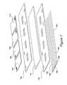
- FIG. 7illustrates a further sensor arrangement.
- FIG. 1A first figure.
- FIG. 1An embodiment of a manually operable sensor is illustrated in FIG. 1 .
- a fabric strip or ribbon 101has a length, illustrated by arrows 102 , that is substantially longer than its width, illustrated by arrow 103 .
- the length of ribbon 101may be typically seven hundred and fifty millimetres (750 mm) with a typical width of twenty-five millimetres (25 mm).
- the fabrichas electrically insulating yarns and electrically conducting yarns included therein.
- the conducting yarnsdefine three conductive tracks 104 , 105 and 106 that are connected to an electrical connector 107 .
- the electrical connectoris provided to facilitate the interfacing of the sensor with an electronic device.
- an active region 108 of the fabricforms part of a sensor assembly that is receptive to a manually applied pressure.
- the fabricis produced by a weaving process in which weft yarns are woven between warp yarns and the conducting yarns, that form tracks 104 , 105 and 106 , are included as part of the warp yarns.
- the fabricis produced in the direction indicated by arrow 102 .
- the conductive yarnsare silver coated nylon and each conductive track 104 to 106 may have between five (5) and ten (10) conducting yarns, with seven (7) conducting yarns being present in a preferred embodiment. Multifilament conductive yarns or threads may be used in the construction of the sensor.
- the spacing between the conductive tracks (the insulating portions)is such that it is greater than the width of the conducting tracks themselves.
- the spacingis made consistent with readily available circuit connectors, such as circuit connector 107 that, typically, facilitates a spacing of two point five millimetres (2.5 mm).
- circuit connector 107that, typically, facilitates a spacing of two point five millimetres (2.5 mm).
- a spacing of five millimetres (5 mm)is achievable, as is preferred in the present embodiment.
- active region 108forms part of a sensor assembly providing discrete switches, in which the application of manual pressure is identified through detection of an electrical connection between two conductive tracks.
- the sensor assemblycomprises a first conductive region 109 and a separate second conductive region 110 .
- a first conductive track 104may apply plus volts to a position 111 of the first conductive region 109 .
- second conductive track 105may apply plus volts to a position 112 of the second conductive region 110 .
- a voltageis applied to conductive track 105
- a voltageis also applied to conductive track 105 in response.
- a functionmay be associated with each of the first and second conductive regions, such that by determining which of the first and second discrete switches has been manipulated, it is possible to determine the actual function that has been selected.
- the data input devicemay include commands for controlling a mobile device such as a radio device, a mobile telephone or an audio player, such as an MP3 player.
- a mobile devicesuch as a radio device, a mobile telephone or an audio player, such as an MP3 player.
- FIG. 3An example of a sensor construction is illustrated in FIG. 3 .
- the sensorincludes a first conductive region 301 and a separate second conductive region 302 .
- the first and second conductive regionsare independent components that are oriented in the same plane 303 .
- both conductive regionsare included in a conductive fabric layer in which they are insulated from one another.
- a separation layer 304is placed between the first and second conductive regions 301 , 302 and an active region 305 of fabric 101 .
- FIG. 3an exploded view is presented but it will be appreciated that, in use, the individual layers are placed in contact.
- electrical conduction in the vertical direction, illustrated by arrow 306is provided by stitching through the layers using conductive threads.
- conductive track 104is electrically connected to a corner 307 of conductive region 301 .
- conductive track 106is electrically connected to a corner 308 of the second conductive region 302 .
- the conductive regions 301 , 302are constructed from carbonised nylon.
- separation layer 304prevents the conductive regions 301 , 302 from being placed into electrical contact with the central third conductive track 105 .
- separation layer 304is compressed and as such electrical connection takes place at the position of the mechanical interaction, that is, where the pressure is applied.
- the masking meansincludes a first mask 309 and a second mask 310 .
- the first mask 309is located above the separation layer 304 and the second mask 310 is located below the separation layer.
- First mask 309defines a first window 311 vertically aligned within first conductive region 301 and a second window 312 vertically aligned within second conductive region 302 .
- second mask 310defines a third window 313 vertically aligned with first window 311 and a fourth window 314 vertically aligned with second window 312 .
- FIG. 4An enhanced embodiment is illustrated in FIG. 4 that deploys additional component layers similar to those disclosed in the aforesaid US patent assigned to the present applicant.
- the single separation layer 304is replaced with three separate layers, a central layer 401 being conductive, while an upper layer 402 is an insulating separator layer and a lower layer 403 is also an insulating separator layer.
- conductionoccurs when manual pressure is applied to a conductive region 301 , 302 .
- the provision of the additional layersprevents accidental triggering when, for example, the material is bent or folded.
- other technical solutionsmay be provided to give the functionality of the separation layer.
- an upper cover 501is preferably provided, along with a lower cover 502 , to protect the operation of the sensor in the active region. Furthermore, an upper waterproof cover 503 and a lower waterproof cover 504 are provided that run the length of the sensor from the active region to the electrical connector.
- the upper cover 601may include graphical representations, illustrated at 603 , which relate to particular device functions.
- these graphical representationsrelate to particular operations of a heat pad, such as on/off and operating temperature control.
- a further sensor arrangementis illustrated in FIG. 7 .
- a fabric strip or ribbon 701defines five conductive tracks 702 , 703 , 704 , 705 and 706 .
- the sensor assemblycomprises four separate conductive regions 707 , 708 , 709 and 710 .
- the sensor assemblyfurther comprises a separation layer 711 , a first mask layer 712 above the separation layer 711 and a second mask layer 713 below the separation layer 711 .
- the switch sensormay be constructed by firstly weaving a fabric with electrically conducting warp yarns that define three conductive tracks that run the length of the fabric.
- An electrical connectoris connected to the conductive tracks at a first end to facilitate the interfacing of the sensor with an electronic device.
- a sensor assemblyis formed that is receptive to manually applied pressure over an active region of the fabric.
Landscapes
- Engineering & Computer Science (AREA)
- Textile Engineering (AREA)
- Push-Button Switches (AREA)
- Woven Fabrics (AREA)
Abstract
Description
Claims (14)
Applications Claiming Priority (3)
| Application Number | Priority Date | Filing Date | Title |
|---|---|---|---|
| GB0622204AGB2443658B (en) | 2006-11-08 | 2006-11-08 | Manually operable sensor |
| GB0622204.6 | 2006-11-08 | ||
| PCT/GB2007/004255WO2008056145A1 (en) | 2006-11-08 | 2007-11-07 | Woven manually operable input device |
Publications (2)
| Publication Number | Publication Date |
|---|---|
| US20100126840A1 US20100126840A1 (en) | 2010-05-27 |
| US8373079B2true US8373079B2 (en) | 2013-02-12 |
Family
ID=37594504
Family Applications (1)
| Application Number | Title | Priority Date | Filing Date |
|---|---|---|---|
| US12/513,037Expired - Fee RelatedUS8373079B2 (en) | 2006-11-08 | 2007-11-07 | Woven manually operable input device |
Country Status (3)
| Country | Link |
|---|---|
| US (1) | US8373079B2 (en) |
| GB (1) | GB2443658B (en) |
| WO (1) | WO2008056145A1 (en) |
Cited By (15)
| Publication number | Priority date | Publication date | Assignee | Title |
|---|---|---|---|---|
| US20100283749A1 (en)* | 2007-09-11 | 2010-11-11 | Peratech Limited | Interfacing Sensors to a Processing Device |
| US8948839B1 (en) | 2013-08-06 | 2015-02-03 | L.I.F.E. Corporation S.A. | Compression garments having stretchable and conductive ink |
| US8945328B2 (en) | 2012-09-11 | 2015-02-03 | L.I.F.E. Corporation S.A. | Methods of making garments having stretchable and conductive ink |
| US9282893B2 (en) | 2012-09-11 | 2016-03-15 | L.I.F.E. Corporation S.A. | Wearable communication platform |
| US9582072B2 (en) | 2013-09-17 | 2017-02-28 | Medibotics Llc | Motion recognition clothing [TM] with flexible electromagnetic, light, or sonic energy pathways |
| US9817440B2 (en) | 2012-09-11 | 2017-11-14 | L.I.F.E. Corporation S.A. | Garments having stretchable and conductive ink |
| US10154791B2 (en) | 2016-07-01 | 2018-12-18 | L.I.F.E. Corporation S.A. | Biometric identification by garments having a plurality of sensors |
| US10159440B2 (en) | 2014-03-10 | 2018-12-25 | L.I.F.E. Corporation S.A. | Physiological monitoring garments |
| US10201310B2 (en) | 2012-09-11 | 2019-02-12 | L.I.F.E. Corporation S.A. | Calibration packaging apparatuses for physiological monitoring garments |
| US10234934B2 (en) | 2013-09-17 | 2019-03-19 | Medibotics Llc | Sensor array spanning multiple radial quadrants to measure body joint movement |
| US10462898B2 (en) | 2012-09-11 | 2019-10-29 | L.I.F.E. Corporation S.A. | Physiological monitoring garments |
| US10467744B2 (en) | 2014-01-06 | 2019-11-05 | L.I.F.E. Corporation S.A. | Systems and methods to automatically determine garment fit |
| US10653190B2 (en) | 2012-09-11 | 2020-05-19 | L.I.F.E. Corporation S.A. | Flexible fabric ribbon connectors for garments with sensors and electronics |
| US11246213B2 (en) | 2012-09-11 | 2022-02-08 | L.I.F.E. Corporation S.A. | Physiological monitoring garments |
| US11772760B2 (en) | 2020-12-11 | 2023-10-03 | William T. Myslinski | Smart wetsuit, surfboard and backpack system |
Families Citing this family (10)
| Publication number | Priority date | Publication date | Assignee | Title |
|---|---|---|---|---|
| US8587422B2 (en) | 2010-03-31 | 2013-11-19 | Tk Holdings, Inc. | Occupant sensing system |
| DE102011006448A1 (en) | 2010-03-31 | 2011-10-06 | Tk Holdings, Inc. | steering wheel sensors |
| US8983732B2 (en) | 2010-04-02 | 2015-03-17 | Tk Holdings Inc. | Steering wheel with hand pressure sensing |
| DE102011006649B4 (en) | 2010-04-02 | 2018-05-03 | Tk Holdings Inc. | Steering wheel with hand sensors |
| WO2013154720A1 (en) | 2012-04-13 | 2013-10-17 | Tk Holdings Inc. | Pressure sensor including a pressure sensitive material for use with control systems and methods of using the same |
| DK2700741T3 (en)* | 2012-08-22 | 2015-04-20 | Kings Metal Fiber Technologies | Control device for use in woven articles |
| WO2014043664A1 (en) | 2012-09-17 | 2014-03-20 | Tk Holdings Inc. | Single layer force sensor |
| GB2548675B (en)* | 2013-05-22 | 2018-01-10 | Rosnes Ltd | Electrical connection point |
| SG11201607544RA (en)* | 2014-03-10 | 2016-10-28 | Jacques Paulino Vacas | Textile motherboard with modular and interchangeable design to monitor, inform and control |
| WO2016175321A1 (en)* | 2015-04-30 | 2016-11-03 | 帝人株式会社 | Piezoelectric element and device using same |
Citations (5)
| Publication number | Priority date | Publication date | Assignee | Title |
|---|---|---|---|---|
| US6210771B1 (en) | 1997-09-24 | 2001-04-03 | Massachusetts Institute Of Technology | Electrically active textiles and articles made therefrom |
| WO2003052541A2 (en) | 2001-12-14 | 2003-06-26 | Infineon Technologies Ag | Keypad integrated into textile items comprising a capacitive readout circuit |
| US20030211797A1 (en) | 2002-05-10 | 2003-11-13 | Hill Ian Gregory | Plural layer woven electronic textile, article and method |
| WO2005073685A1 (en) | 2004-02-02 | 2005-08-11 | Eleksen Limited | Linear pressure sensor |
| WO2006030230A1 (en) | 2004-09-16 | 2006-03-23 | Sentrix Technology Limited | Switches and devices for textile artcles |
Family Cites Families (3)
| Publication number | Priority date | Publication date | Assignee | Title |
|---|---|---|---|---|
| HK1048192B (en)* | 2000-03-30 | 2005-08-26 | Eleksen Limited | Detector constructed from electrically conducting fabric |
| CN1286000C (en)* | 2000-04-03 | 2006-11-22 | 布鲁内尔大学 | Conductive pressure sensitive textile |
| GB0209888D0 (en)* | 2002-04-30 | 2002-06-05 | Koninkl Philips Electronics Nv | Switch |
- 2006
- 2006-11-08GBGB0622204Apatent/GB2443658B/ennot_activeExpired - Fee Related
- 2007
- 2007-11-07USUS12/513,037patent/US8373079B2/ennot_activeExpired - Fee Related
- 2007-11-07WOPCT/GB2007/004255patent/WO2008056145A1/enactiveApplication Filing
Patent Citations (5)
| Publication number | Priority date | Publication date | Assignee | Title |
|---|---|---|---|---|
| US6210771B1 (en) | 1997-09-24 | 2001-04-03 | Massachusetts Institute Of Technology | Electrically active textiles and articles made therefrom |
| WO2003052541A2 (en) | 2001-12-14 | 2003-06-26 | Infineon Technologies Ag | Keypad integrated into textile items comprising a capacitive readout circuit |
| US20030211797A1 (en) | 2002-05-10 | 2003-11-13 | Hill Ian Gregory | Plural layer woven electronic textile, article and method |
| WO2005073685A1 (en) | 2004-02-02 | 2005-08-11 | Eleksen Limited | Linear pressure sensor |
| WO2006030230A1 (en) | 2004-09-16 | 2006-03-23 | Sentrix Technology Limited | Switches and devices for textile artcles |
Cited By (23)
| Publication number | Priority date | Publication date | Assignee | Title |
|---|---|---|---|---|
| US20100283749A1 (en)* | 2007-09-11 | 2010-11-11 | Peratech Limited | Interfacing Sensors to a Processing Device |
| US10201310B2 (en) | 2012-09-11 | 2019-02-12 | L.I.F.E. Corporation S.A. | Calibration packaging apparatuses for physiological monitoring garments |
| US10258092B2 (en) | 2012-09-11 | 2019-04-16 | L.I.F.E. Corporation S.A. | Garments having stretchable and conductive ink |
| US9282893B2 (en) | 2012-09-11 | 2016-03-15 | L.I.F.E. Corporation S.A. | Wearable communication platform |
| US11246213B2 (en) | 2012-09-11 | 2022-02-08 | L.I.F.E. Corporation S.A. | Physiological monitoring garments |
| US9817440B2 (en) | 2012-09-11 | 2017-11-14 | L.I.F.E. Corporation S.A. | Garments having stretchable and conductive ink |
| US9986771B2 (en) | 2012-09-11 | 2018-06-05 | L.I.F.E. Corporation S.A. | Garments having stretchable and conductive ink |
| US10045439B2 (en) | 2012-09-11 | 2018-08-07 | L.I.F.E. Corporation S.A. | Garments having stretchable and conductive ink |
| US11013275B2 (en) | 2012-09-11 | 2021-05-25 | L.I.F.E. Corporation S.A. | Flexible fabric ribbon connectors for garments with sensors and electronics |
| US10736213B2 (en) | 2012-09-11 | 2020-08-04 | L.I.F.E. Corporation S.A. | Physiological monitoring garments |
| US10462898B2 (en) | 2012-09-11 | 2019-10-29 | L.I.F.E. Corporation S.A. | Physiological monitoring garments |
| US8945328B2 (en) | 2012-09-11 | 2015-02-03 | L.I.F.E. Corporation S.A. | Methods of making garments having stretchable and conductive ink |
| US10653190B2 (en) | 2012-09-11 | 2020-05-19 | L.I.F.E. Corporation S.A. | Flexible fabric ribbon connectors for garments with sensors and electronics |
| US8948839B1 (en) | 2013-08-06 | 2015-02-03 | L.I.F.E. Corporation S.A. | Compression garments having stretchable and conductive ink |
| US10234934B2 (en) | 2013-09-17 | 2019-03-19 | Medibotics Llc | Sensor array spanning multiple radial quadrants to measure body joint movement |
| US9582072B2 (en) | 2013-09-17 | 2017-02-28 | Medibotics Llc | Motion recognition clothing [TM] with flexible electromagnetic, light, or sonic energy pathways |
| US10467744B2 (en) | 2014-01-06 | 2019-11-05 | L.I.F.E. Corporation S.A. | Systems and methods to automatically determine garment fit |
| US10699403B2 (en) | 2014-01-06 | 2020-06-30 | L.I.F.E. Corporation S.A. | Systems and methods to automatically determine garment fit |
| US10159440B2 (en) | 2014-03-10 | 2018-12-25 | L.I.F.E. Corporation S.A. | Physiological monitoring garments |
| US10869620B2 (en) | 2016-07-01 | 2020-12-22 | L.I.F.E. Corporation S.A. | Biometric identification by garments having a plurality of sensors |
| US10154791B2 (en) | 2016-07-01 | 2018-12-18 | L.I.F.E. Corporation S.A. | Biometric identification by garments having a plurality of sensors |
| US11772760B2 (en) | 2020-12-11 | 2023-10-03 | William T. Myslinski | Smart wetsuit, surfboard and backpack system |
| US11952087B2 (en) | 2020-12-11 | 2024-04-09 | Alessandra E. Myslinski | Smart apparel and backpack system |
Also Published As
| Publication number | Publication date |
|---|---|
| WO2008056145A1 (en) | 2008-05-15 |
| US20100126840A1 (en) | 2010-05-27 |
| GB2443658A (en) | 2008-05-14 |
| GB0622204D0 (en) | 2006-12-20 |
| GB2443658B (en) | 2011-09-14 |
Similar Documents
| Publication | Publication Date | Title |
|---|---|---|
| US8373079B2 (en) | Woven manually operable input device | |
| US8169295B2 (en) | Manually operable position sensor | |
| US11124904B2 (en) | Conductive signal paths in woven fabrics | |
| US6714117B2 (en) | Detector constructed from fabric | |
| EP1282906B1 (en) | Flexible switching devices | |
| US8089336B2 (en) | Position detection | |
| CN106051846A (en) | Induction hob and flexible support for an induction hob | |
| US20180255639A1 (en) | Micro conductive thread interconnect component to make an interconnect between conductive threads in fabrics to pcb, fpc, and rigid-flex circuits | |
| WO2008044167A3 (en) | Textile for connection of electronic devices | |
| US20080105527A1 (en) | Switches and Devices for Integrated Soft Component Systems | |
| US20070056493A1 (en) | Electrical conductor element | |
| US20220244112A1 (en) | Load sensor | |
| JPH10144168A (en) | Planar switch | |
| WO2008044202A3 (en) | Textile for connection of electronic devices | |
| KR102185565B1 (en) | Conductive composite yarn capable of sensing the force in vertical and horizontal direction and textile sensor having the same | |
| WO2024024301A1 (en) | Load sensor | |
| GB2461712A (en) | Advanced fabric control switch | |
| CN110838569B (en) | Battery contact system for a modularly constructed battery pack | |
| GB2144917A (en) | Membrane switches | |
| EP2700741B1 (en) | Control device for use in woven article | |
| WO2021132771A1 (en) | Conductive composite yarn capable of measuring tension in horizontal direction and pressure in vertical direction, and fabric sensor comprising same | |
| CN222318279U (en) | Pressure-sensing mats, seat comfort systems and smart devices | |
| CN220400905U (en) | Super-flexible connection structure of fabric circuit | |
| WO2002052391A2 (en) | Manually operable remote controller | |
| CA1247716A (en) | Operating key unit |
Legal Events
| Date | Code | Title | Description |
|---|---|---|---|
| AS | Assignment | Owner name:PERATECH LIMITED, UNITED KINGDOM Free format text:ASSIGNMENT OF ASSIGNORS INTEREST;ASSIGNOR:WALKINGTON, STUART MARK;REEL/FRAME:023845/0009 Effective date:20091115 | |
| STCF | Information on status: patent grant | Free format text:PATENTED CASE | |
| FEPP | Fee payment procedure | Free format text:PAYOR NUMBER ASSIGNED (ORIGINAL EVENT CODE: ASPN); ENTITY STATUS OF PATENT OWNER: SMALL ENTITY | |
| AS | Assignment | Owner name:TOMTOM INTERNATIONAL B.V., NETHERLANDS Free format text:ASSIGNMENT OF ASSIGNORS INTEREST;ASSIGNOR:PERATECH LIMITED;REEL/FRAME:034171/0037 Effective date:20140508 | |
| AS | Assignment | Owner name:WEARABLE TECHNOLOGY LIMITED, UNITED KINGDOM Free format text:ASSIGNMENT OF ASSIGNORS INTEREST;ASSIGNOR:TOMTOM INTERNATIONAL B.V.;REEL/FRAME:035446/0851 Effective date:20150325 | |
| FEPP | Fee payment procedure | Free format text:PAT HOLDER CLAIMS SMALL ENTITY STATUS, ENTITY STATUS SET TO SMALL (ORIGINAL EVENT CODE: LTOS); ENTITY STATUS OF PATENT OWNER: SMALL ENTITY | |
| FPAY | Fee payment | Year of fee payment:4 | |
| FEPP | Fee payment procedure | Free format text:MAINTENANCE FEE REMINDER MAILED (ORIGINAL EVENT CODE: REM.); ENTITY STATUS OF PATENT OWNER: SMALL ENTITY | |
| LAPS | Lapse for failure to pay maintenance fees | Free format text:PATENT EXPIRED FOR FAILURE TO PAY MAINTENANCE FEES (ORIGINAL EVENT CODE: EXP.); ENTITY STATUS OF PATENT OWNER: SMALL ENTITY | |
| STCH | Information on status: patent discontinuation | Free format text:PATENT EXPIRED DUE TO NONPAYMENT OF MAINTENANCE FEES UNDER 37 CFR 1.362 | |
| FP | Lapsed due to failure to pay maintenance fee | Effective date:20210212 |