US8372561B2 - Composite fluid storage unit with internal fluid distribution feature - Google Patents
Composite fluid storage unit with internal fluid distribution featureDownload PDFInfo
- Publication number
- US8372561B2 US8372561B2US12/052,848US5284808AUS8372561B2US 8372561 B2US8372561 B2US 8372561B2US 5284808 AUS5284808 AUS 5284808AUS 8372561 B2US8372561 B2US 8372561B2
- Authority
- US
- United States
- Prior art keywords
- fluid
- fluid storage
- storage unit
- composite
- storage material
- Prior art date
- Legal status (The legal status is an assumption and is not a legal conclusion. Google has not performed a legal analysis and makes no representation as to the accuracy of the status listed.)
- Expired - Fee Related
Links
Images


Classifications
- H—ELECTRICITY
- H01—ELECTRIC ELEMENTS
- H01M—PROCESSES OR MEANS, e.g. BATTERIES, FOR THE DIRECT CONVERSION OF CHEMICAL ENERGY INTO ELECTRICAL ENERGY
- H01M8/00—Fuel cells; Manufacture thereof
- H01M8/04—Auxiliary arrangements, e.g. for control of pressure or for circulation of fluids
- H01M8/04082—Arrangements for control of reactant parameters, e.g. pressure or concentration
- H01M8/04201—Reactant storage and supply, e.g. means for feeding, pipes
- H01M8/04216—Reactant storage and supply, e.g. means for feeding, pipes characterised by the choice for a specific material, e.g. carbon, hydride, absorbent
- H—ELECTRICITY
- H01—ELECTRIC ELEMENTS
- H01M—PROCESSES OR MEANS, e.g. BATTERIES, FOR THE DIRECT CONVERSION OF CHEMICAL ENERGY INTO ELECTRICAL ENERGY
- H01M8/00—Fuel cells; Manufacture thereof
- H01M8/04—Auxiliary arrangements, e.g. for control of pressure or for circulation of fluids
- H01M8/04082—Arrangements for control of reactant parameters, e.g. pressure or concentration
- H01M8/04201—Reactant storage and supply, e.g. means for feeding, pipes
- H01M8/04208—Cartridges, cryogenic media or cryogenic reservoirs
- Y—GENERAL TAGGING OF NEW TECHNOLOGICAL DEVELOPMENTS; GENERAL TAGGING OF CROSS-SECTIONAL TECHNOLOGIES SPANNING OVER SEVERAL SECTIONS OF THE IPC; TECHNICAL SUBJECTS COVERED BY FORMER USPC CROSS-REFERENCE ART COLLECTIONS [XRACs] AND DIGESTS
- Y02—TECHNOLOGIES OR APPLICATIONS FOR MITIGATION OR ADAPTATION AGAINST CLIMATE CHANGE
- Y02E—REDUCTION OF GREENHOUSE GAS [GHG] EMISSIONS, RELATED TO ENERGY GENERATION, TRANSMISSION OR DISTRIBUTION
- Y02E60/00—Enabling technologies; Technologies with a potential or indirect contribution to GHG emissions mitigation
- Y02E60/30—Hydrogen technology
- Y02E60/50—Fuel cells
Definitions
- Composite fluid storage materialsmay be combined with enclosures, such as conformable enclosures, to provide a composite fluid storage unit that is lightweight and composed primarily of active fluid storage material.
- Composite hydrogen storage materialsare examples. The mass and volume of non-storage materials is very low, resulting in fluid storage densities approaching the limit of the bulk storage material itself.
- the composite fluid storage materialmay be a porous, elastic solid. Any fluid entering or leaving the storage unit must be transported through the solid. Therefore, as the density of the solid increases to pack more active material into the enclosure, the ability to transport fluid is decreased of composite fluid storage materials.
- the composite fluid storage unitmay be utilized with a fuel cell, for example.
- the fuel cellmay demand a flowrate of fluid at a high enough level to generate the consistent power required for its intended purpose. This flowrate can often be quite high, depending on the application. Similarly, when attempting to achieve a fast refueling of the storage unit, the flowrate of fluid into the unit must also be high. The flowrate, heat transfer and homogeneity of the fluid into or out of the composite fluid storage material are severely limited by the low porosity of the material.
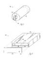
- FIG. 1illustrates a perspective view of a composite fluid storage unit including an internal fluid distribution feature, according to some embodiments.
- FIG. 2illustrates a perspective view of a composite fluid storage unit including multiple features, according to some embodiments.
- FIG. 3illustrates a perspective view of a cylindrical fluid storage unit including an internal fluid distribution feature, according to some embodiments.
- FIG. 4illustrates a perspective view of a composite fluid storage unit utilizing a planar interface, according to some embodiments.
- FIG. 5illustrates a perspective view of a composite fluid storage unit including a preformed internal fluid distribution feature, according to some embodiments.
- FIG. 6illustrates a perspective view of a composite fluid storage unit and a sacrificial preform, according to some embodiments.
- FIG. 7illustrates a perspective view of a fuel cell system, according to some embodiments.
- FIG. 8illustrates a block flow diagram of a method of making a composite fluid storage unit utilizing an internal fluid distribution feature, according to some embodiments.
- FIG. 9illustrates a block flow diagram of a method of operating a fluid storage unit, according to some embodiments.
- Embodiments of the inventionrelate to a fluid storage unit comprising a composite fluid storage material and one or more internal fluid distribution features.
- the storage unitmay also comprise an enclosure, at least partially surrounding the composite fluid storage material.
- Embodimentsalso relate to a fuel cell system.
- the systemrelates to a fluid enclosure including a composite fluid storage material, one or more internal fluid distribution features and one or more fuel cell layers in fluidic communication with the fluid enclosure.
- Embodimentsalso relate to a method of making a fluid storage unit, the method comprising forming a composite fluid storage material and forming one or more internal fluid distribution features.
- Other methodsinclude methods of operating a fluid enclosure and methods of delivering a fluid.
- Embodiments of the inventionrelate to a composite fluid storage unit that includes a composite fluid storage material and one or more internal fluid distribution features.
- the featuresmay provide an increased homogeneity in the composite fluid storage material or an increased uniformity in reaction sites or contacting sites for a fluid.
- the unithas an increased maximum flowrate for fluid into or out of the unit as compared to the maximum flow rate of the bulk composite fluid storage material alone when sized similarly to the composite fluid storage unit.
- the one or more internal fluid distribution featuresfacilitate or enhance the transfer of fluid into or out of the unit, which may be in contact with a device that utilizes fluid as a power source, such as a fuel cell.
- the increased flowrateallows for the storage unit to refuel faster and also to keep up with the power demands of many types of external devices.
- the featuresalso allow for more efficient and rapid heat transfer, thus allowing for quicker reaction rates of fluid storage and delivery.
- electrochemical layerrefers to a sheet including one or more active functional members of an electrochemical cell.
- an electrochemical layermay include a fuel cell layer.
- active functional membersrefers to components of an electrochemical cell that function to convert chemical energy to electrical energy or convert electrical energy to chemical energy. Active functional members exhibit ion-conductivity, electrical conductivity, or both.
- electrochemical cellrefers to a device that converts chemical energy to electrical energy or converts electrical energy to chemical energy.
- electrochemical cellsmay include galvanic cells, electrolytic cells, electrolyzers, fuel cells, batteries and metal-air cells, such as zinc air fuel cells or batteries.
- Any suitable type of electrochemical cell including fuel cells and appropriate materialscan be used according to the present invention including without limitation proton exchange membrane fuel cells (PEMFCs), solid oxide fuel cells (SOFCs), molten carbonate fuel cell (MCFCs), alkaline fuel cells, other suitable fuel cells, and materials thereof.
- fuel cellsinclude proton exchange membrane fuel cells, direct methanol fuel cells, alkaline fuel cells, phosphoric acid fuel cells, molten carbonate fuel cells or solid oxide fuel cells.
- fluidrefers to a continuous, amorphous substance whose molecules move freely past one another and that has the tendency to assume the shape of its container.
- a fluidmay be a gas, liquefied gas, liquid or liquid under pressure.
- fluidsmay include fluid reactants, fuels, oxidants, and heat transfer fluids.
- Fluid fuels used in fuel cellsmay include hydrogen gas or liquid and hydrogen carriers in any suitable fluid form.
- fluidsexamples include air, oxygen, water, hydrogen, alcohols such as methanol and ethanol, ammonia and ammonia derivatives such as amines and hydrazine, silanes such as disilane, trisilane, disilabutane, complex metal hydride compounds such as aluminum borohydride, boranes such as diborane, hydrocarbons such as cyclohexane, carbazoles such as dodecahydro-n-ethyl carbazole, and other saturated cyclic, polycyclic hydrocarbons, saturated amino boranes such as cyclotriborazane, butane, borohydride compounds such as sodium and potassium borohydrides, and formic acid.
- alcoholssuch as methanol and ethanol
- ammonia and ammonia derivativessuch as amines and hydrazine
- silanessuch as disilane, trisilane, disilabutane
- complex metal hydride compoundssuch as aluminum borohydride, bora
- fluid enclosuremay refer to a device for storing a fluid.
- the fluid enclosuremay store a fluid physically or chemically.
- the fluid enclosuremay chemically store a fluid in active material particles.
- a fluid enclosuremay also refer to a fluid enclosure including active material particles and an outer enclosure wall, conformably coupled to the fluid storage component and may also include structural fillers. Examples of such a fluid enclosure are found in commonly-owned U.S. patent application Ser. No. 11/473,591, which was filed Jun. 23, 2006, and published on Dec. 27, 2007 as U.S. Patent App. Pub. 2007/0295617 and whose disclosure is incorporated by reference herein in its entirety.
- composite fluid storage materialrefers to active material particles mixed with a binder, wherein the binder immobilizes the active material particles sufficient to maintain relative spatial relationships between the active material particles. Examples of composite fluid storage materials are found in commonly-owned U.S. patent application Ser. No. 11/379,970, which was filed
- An example of a composite fluid storage materialis a composite hydrogen storage material.
- the composite fluid storage materialscan have sufficient structural strength with a proper binder to withstand the strain induced by charging and discharging the active material particles without causing the composite to fracture. Structural strength of the composite fluid storage material allows it to be used as a load bearing member that can resist the force exerted by the hydrogen absorbing into the metal hydride particles. Due to this ability to resist the force produced by particle strain, the composite hydrogen storage material is able to retain its structural integrity and remain as a solid during multiple occlusion and desorption cycles.
- the composite hydrogen storage materialmay be shaped as pellets, discs, spheres, wafers, rectangular wafers or any porous or geometric shape.
- relative spatial relationshipsrefers to three-dimensional relationships between particles. Such three-dimensional relationships between particles in the context of the present invention will remain substantially unchanged. For example, the distance between particles may change during the hydriding/ldehydriding cycle, but the particles return to substantially the same position relative to the other particles over the course of one complete cycle.
- the particle structuremay have, e.g., an elastic property, in that the particles may move, but maintain substantially the same three-dimensional positioning substantially relative to other particles as they move.
- An exemplary indicator of whether a material meets the above characteristicsis a qualitative measurement based upon, e.g., the volume, packing density or porosity or a dimension (e.g. length) of the composite material over repeated cycles. As such, when length of the formed composite is used as the indicator, the length of the formed composite will be at least about 80% and not more than about 120% of the parent length measured.
- active material particlesrefer to material particles capable of storing hydrogen or other fluids or to material particles that may occlude and desorb hydrogen or another fluid. Active material particles may include fluid-storing materials that occlude fluid, such as hydrogen, by chemisorption, physisorption or a combination thereof. Some hydrogen-storing materials desorb hydrogen in response to stimuli, such as change in temperature, change in heat or a change in pressure.
- Examples of hydrogen-storing materials that release hydrogen in response to stimuliinclude metal hydrides, chemical hydrides, suitable micro-ceramics, nano-ceramics, boron nitride nanotubes, metal organic frameworks, palladium-containing materials, zeolites, silicas, aluminas, graphite, and carbon-based reversible fluid-storing materials such as suitable carbon nanotubes, carbon fibers, carbon aerogels, and activated carbon, nano-structured carbons or any combination thereof.
- the particlesmay also include a metal, a metal alloy, a metal compound capable of forming a metal hydride when in contact with hydrogen, alloys thereof or combinations thereof.
- the active material particlesmay include magnesium, lithium, aluminum, calcium, boron, carbon, silicon, transition metals, lanthanides, intermetallic compounds, solid solutions thereof, or combinations thereof.
- the active material particlesare mixed with a binder, such as a thermoplastic binder.
- a bindersuch as a thermoplastic binder.
- suitable bindersinclude polypropylene, polyethylene, polyvinylidene fluoride (PVDF), hexaflouropropylene vinylidene fluoride copolymer, cross-linked copolymers, polytetrafluoroethylene (PTFE), perfluoro alkoxy (PFA), thermoplastic polyesters (for example, Nylon.TM).
- PVDFpolyvinylidene fluoride
- PTFEpolytetrafluoroethylene
- PFAperfluoro alkoxy
- thermoplastic polyestersfor example, Nylon.TM.
- the bindermay be readily melt-processable and may have an elongation to break of at least about 20%, for example.
- the amount of bindermay be about 50% by weight or less of the mixture.
- the bindermay be flexible enough to withstand the strain produced during a charging and dis
- metal hydridesmay include a metal, metal alloy or metal compound capable of forming a metal hydride when in contact with hydrogen.
- Metal hydride compoundscan be generally represented as follows: AB, AB 2 , A 2 B, AB 5 and BCC, respectively. When bound with hydrogen, these compounds form metal hydride complexes.
- composite hydrogen storage materialrefers to active material particles mixed with a binder, wherein the binder immobilizes the active material particles sufficient to maintain relative spatial relationships between the active material particles.
- occludeor “occluding” or “occlusion” refers to absorbing or adsorbing and retaining a substance, such as a fluid.
- Hydrogenmay be a fluid occluded, for example.
- the fluidmay be occluded chemically or physically, such as by chemisorption or physisorption, for example.
- desorbor “desorbing” or “desorption” refers to the removal of an absorbed or adsorbed substance.
- Hydrogenmay be removed from active material particles, for example.
- the hydrogen or other fluidmay be bound physically or chemically, for example.
- contactingrefers to physically, chemically, electrically touching or within sufficiently close proximity.
- a fluidmay contact an enclosure, in which the fluid is physically forced inside the enclosure, for example.
- the composite fluid storage unit 100may include composite fluid storage material 102 surrounded by an enclosure 104 .
- the enclosure 104may partially or completely enclose the composite fluid storage material 102 .
- An internal fluid distribution feature 108may be formed in the unit 100 and include an aperture 106 .
- Multiple internal fluid distribution features 204may be formed in a unit 200 and include multiple apertures 202 (see FIG. 2 ). The fluid flows into or out of the unit 100 through the one or more apertures 106 , 202 .
- a composite fluid storage material 102refers to active material particles mixed with a binder, wherein the binder immobilizes the active material particles sufficient to maintain relative spatial relationships between the active material particles.
- a composite fluid storage material 102may include composite hydrogen storage materials, for example.
- Active material particlesare material particles capable of storing fluid or material particles that may occlude and desorb a fluid, such as metal hydrides, for example.
- the active materialmay be a metal, metal alloy or metal compound capable of forming a metal hydride when in contact with hydrogen.
- the internal fluid distribution feature 108may be of many shapes or sizes.
- the feature 108may be a borehole, for example.
- the internal fluid distribution feature 108may be drilled after forming of the unit 100 .
- the feature 108may be formed directly in the composite fluid storage material 102 or formed after the storage material 102 has been surrounded by an enclosure 104 .
- the diameter, depth and shape of the internal fluid distribution feature 108may be determined to increase the surface area of the composite fluid storage material 102 exposed to the open space within the internal fluid distribution feature 108 . By increasing this surface area, while maintaining structural stability, the flowrate of fluid into or out of the unit 100 may be increased.
- the features 108may also increase the transfer of heat into or out of the fluid storage unit or enclosure 104 , within the composite fluid storage material 102 or both.
- the featuresmay also facilitate the occluding/desorbing of fluid storage or delivery.
- the features 108may also increase the uniformity in occluding a fluid, uniformity in desorbing a fluid or both.
- the one or more internal fluid distribution features 108may be arranged so as to maintain structural integrity of the unit or enclosure.
- the one or more internal fluid distribution features 202may also be connected via an external manifold system, for example.
- the diameter, depth and shape of the one or more features 108 , 202may be determined experimentally or computationally, once the transport characteristics of the bulk material have been identified.
- the internal fluid distribution feature 108 or one or more internal fluid distribution features 202may include apertures 106 , 202 .
- the apertures 106 , 202may independently or in combination with other internal fluid distribution features 108 , 202 increase the maximum flowrate of the composite fluid storage unit 100 , 200 , assist in heat transfer or otherwise increase the effective transfer of a fluid into or out of the storage material 102 .
- the apertures 106 , 202may include multiple surface apertures and high aspect ratio surface apertures, for example.
- An aperturecan be an internal fluid distribution feature, so long as it contributes to an increase in unit effectiveness.
- One or more portsmay also be part of, integrated into or in contact with the unit or enclosure. The one or more ports may be configured to transfer fluid to the unit, transfer fluid from the unit or both. The port may be an aperture or vice versa, for example
- the flowratemay refer to the movement of mass per time. Volumetric flowrate may also be measured, but may not be as practical.
- the maximum flowrate of fluidmay be measured by mass flow meters.
- the maximum flowrate that can be obtained from composite fluid storage materialis at least partially governed by the internal massflow limitations of the porous material and the exposed surface area which serves as the interface between transport through porous media and transport through open space. The increase in massflow is therefore proportional to the increase in the exposed area.
- the embodiments of the present inventionmay increase the maximum flowrate of the composite fluid storage unit by a factor of about 5, about 10, or about 10 or more, for example.
- the enclosure 104may be a fluid enclosure formed by conformably coupling an outer wall to the composite fluid storage material 102 , for example.
- Conformably coupledrefers to forming a bond that is substantially uniform between two components and are attached in such as way as to chemically or physically bind in a corresponding shape or form.
- a structural filler or composite fluid storage materialmay be conformably coupled to an outer enclosure wall, for example, in which the outer enclosure wall chemically or physically binds to the structural filler or composite fluid storage material and takes its shape. As the force due to internal pressure within the fluid enclosure increases, the load may be transferred directly into a tensile load on the structural filler or composite fluid storage material, rather than internal pressure being amplified into tensile load on the outer enclosure wall.
- the internal pressure of the fluid enclosuremay be affected by the amount of fluid stored.
- the amount of stress applied to the fluid enclosuremay be affected by the mechanical stress associated with contacting/releasing a fluid from a storage material, such as hydrogen occluding/desorbing from a metal hydride, for example.
- the outer enclosure wallis the outermost layer within a fluid enclosure that serves to at least partially slow the diffusion of a fluid from the enclosure.
- the outer enclosure wallmay include multiple layers of the same or differing materials.
- the outer enclosure wallmay include a polymer or a metal, for example.
- the fluidmay be hydrogen, for example. Examples of such enclosures may be found in commonly owned U.S. patent application Ser. No. 11/473,591, which was filed Jun. 23, 2006, and published on Dec. 27, 2007 as U.S. Patent App. Pub. 2007/0295617.
- the fluid enclosure 104may be protected with one or more pressure relief components of the self-destructive type, such as fusible triggers, rupture disks and diaphragms, or of the re-sealable type, such as a spring-loaded pressure-relief valve.
- a pressure relief componentmay be “pressure-activated”, set to activate at a certain pressure. Alternately, a pressure relief component may be “thermally-activated”, set to activate at a certain temperature. A pressure relief component may also be both “pressure-activated” and “thermally-activated”.
- the composite fluid storage unit 400may include a composite fluid storage material 404 partially surrounded by enclosure 402 .
- the composite fluid storage material 404may be exposed by aperture 406 .
- the relatively large aperture 406may allow for the composite fluid storage material 404 to be in contact with a planar interface 408 .
- the shape and position of the aperture 406may be of many types, such as serpentine or channeled, for example.
- the aperture 406may include multiple apertures or sets of apertures, such as sets of serpentine, grooved or channeled apertures. Multiple, smaller apertures may better support the internal pressure of the unit. Multiple apertures, large apertures, serpentine openings, grooves, surface channels and other surface features may be considered internal fluid distribution features.
- the planar interface 408may include a port 410 for fluidic connectivity.
- the planar interface 408may support, enclose, or connect to valves, pressure regulators or other planar interface devices, for example. Examples of such devices are discussed in Mclean et al., U.S. patent application Ser. No. 12/053,374, filed on Mar. 21, 2008, published as U.S. Patent App. Pub. 2008/0233446 on Sep. 25, 2008, and entitled “FLUIDIC CONTROL SYSTEM AND METHOD OF MANUFACTURE,” and Zimmermann et al., U.S. patent application Ser. No. 60/919,470, filed on Mar.
- the composite fluid storage unit 500includes an enclosure 104 that surrounds composite fluid storage material 102 .
- a channeled feature 502 with aperture 106may be formed in the unit 500 .
- the channeled feature 502may allow for a deeper penetration of fluid into the composite material 102 .
- the surface area exposed to the open spacewould be greatly increased and higher flow rates, heat transfer rates or other efficiencies may be achieved. The higher flow rates may be useful in applications involving large format enclosures or in supplying devices with high power demands.
- the unitmay allow for a fluid delivery of a stoichiometric ratio of greater to or equal to one to an electrochemical cell layer.
- the electrochemical cell layerwould not be “fuel-starved” as the unit may provide an increased flowrate and volume of fuel. This may be helpful, for instance, in which the electrochemical cell layer is a fuel cell layer and an increased flow rate and volume of fuel may be required to maintain high power demands from an external or portable device.
- the channeled feature 502may be formed by cross drilling boreholes into the unit 500 .
- the channeled feature 502may be formed in-situ as the composite fluid storage material 102 is being formed.
- the channeled feature 502may be formed by utilizing a preform 602 (see FIG. 6 ), for example.
- the preform 602may be porous and left in the unit 500 or may be sacrificial and eventually removed.
- the preform 602may be manufactured of a porous polymer, porous carbon or porous metal. If sacrificial, the preform 602 may be manufactured of wax, low temperature polymer, a water soluble material or any material that can be removed once the unit 500 is formed.
- the removal of the sacrificial preformmay be accomplished by heating, dissolving, irradiating, or other methods so as to remove the material and leave a channeled feature 502 .
- the feature 502may be formed by contacting two or more composite fluid storage material units with surface features to form an internal feature, for example.
- a flexible enclosure 702may include one or more internal fluid distribution features 704 .
- One or more optional ports 706may also be in contact with or integrated into the enclosure 702 .
- One or more electrochemical cell layers 710may be contact with the enclosure 702 .
- An optional fluidic control layer 708 or systemmay be in fluidic contact with the one or more electrochemical cell layers 710 and the enclosure 702 .
- the electrochemical cell layers 710may be fuel cell layers, for example.
- the one or more internal fluid distribution features 704allow for an increased rate of fluid transfer between the fluid enclosure 702 and the one or more fuel cell layers 710 .
- the features 704may enhance heat transfer, uniformity of distribution of a fluid within the storage material, uniformity in reaction sites, reaction rate or number of reactions, for example.
- the systemmay also include a removable planar interface, such as in contact with the enclosure 702 , for example.
- the optional fluidic control layer 708may include one or features, devices or components configured to affect the flow of fluid into or out of the enclosure 702 . Such devices or components may be arrays of fluidic controllers, regulators, valves, etc.
- the one or more electrochemical cell layers 710may include an electrochemical cell layer including a plurality of unit cells constructed by providing a substrate including a plurality of ion conducting regions.
- a substratecould be provided, for example by selectively treating a sheet of non- or partially-conducting material to form the ion conducting regions, or by selectively treating a sheet of ion conducting material to form non-conducting regions, as described, for example in the commonly-assigned application Ser. No. 11/047,558, which was filed 4 Feb. 2005, published as U.S. Patent App. Pub. 2005/0249994 on 10 Nov.
- Unit cells according to the inventionmay be used in a planar electrochemical cell layer that is conformable to other geometries, as described in application Ser. No. 11/185,755, which was filed on 21 Jul. 2005, published as U.S. Patent App. Pub. 2007/0090786, and entitled “DEVICES POWERED BY CONFORMABLE FUEL CELLS” and application Ser. No. 60/975,132, filed 25 Sep. 2007, and entitled “FLEXIBLE FUEL CELL,” which are hereby incorporated by reference.
- Arrays of unit cellscan be constructed to provide varied-power generating electrochemical cell layers in which the entire electrochemical structure is contained within the layer. This means additional components such as plates for collecting currents etc. can be eliminated, or replaced with structures serving different functions. Structures like those described herein are well adapted to be manufactured by continuous processes. Such structures can be designed in a way which does not require the mechanical assembly of individual parts. In some embodiments, the conductive path lengths within this structure may be kept extremely short so that ohmic losses in the catalyst layer are minimized.
- Arraymay refer to a plurality of individual unit cells.
- the plurality of cellsmay be formed on a sheet of ion exchange membrane material, a substrate, or may be formed by assembling a number of components in a particular manner.
- Arrayscan be formed to any suitable geometry. Examples of planar arrays of fuel cells are described in co-owned U.S. application Ser. No. 11/047,560, which was filed on 2 Feb. 2005, published on 10 Nov. 2005 as U.S. Patent App. Pub. 2005/0250004, and entitled “ELECTROCHEMICAL CELLS HAVING CURRENT CARRYING STRUCTURES UNDERLYING ELECTROCHEMICAL REACTION LAYERS”, the disclosure of which is herein incorporated by reference in its entirety. Fuel cells in an array can also follow other planar surfaces, such as tubes as found in cylindrical fuel cells. Alternately or in addition, the array can include flexible materials that can be conformed to other geometries.
- Fuel cell layersmay also include thin frame fuel cell structures and compact fuel cell layers. Examples of such embodiments may be found in commonly owned U.S. patents “FUEL CELL WITH REACTOR FRAME” and “COMPACT FUEL CELL LAYER”, U.S. Pat. Nos. 7,241,525 and 7,067,217 respectively, the disclosures of which are herein incorporated by reference in their entirety.
- a composite fluid storage materialmay be formed 802 .
- Forming 802may include pressing and heating, for example.
- One or more internal fluid distribution featuresmay be formed 804 in the composite fluid storage material.
- Forming 804may include drilling, embossing, compression molding, placing a porous preform or removing a sacrificial preform, for example.
- An enclosuremay be formed to partially or fully enclose the composite fluid storage material.
- the one or more internal fluid distribution featuresmay be formed before or after the enclosure being formed, for example.
- Internal featuresmay be formed 804 by contacting two or more composite fluid storage material units with surface features, thereby forming internal features when contacted, for example.
- a fluidmay be desorbed 902 from a composite fluid storage material.
- the fluidmay then contact 904 one or more electrochemical cell layers of an electronic device.
- the composite fluid storage materialincludes one or more internal fluid distribution features.
- the internal fluid distribution featuresmay increase a flow rate, heat transfer rate, uniformity of fluid distribution, reaction rate or other properties to enhance the transfer of fluid from the composite fluid storage material to the one or more electrochemical cell layers.
- the flow rate, volume of fluid or bothmay greater than or equal to a rate of fluid consumption by the one or more fuel cell layers. If an external device requires a high power demand, the flowrate may be greater than or equal to the consumption rate such that the electrochemical cell layers or external device are not starved for fuel.
- a composite fluid storage material within the unit or enclosuremay be contacted with a fluid.
- the one or more internal fluid distribution featuresmay increase a rate of contacting with a fluid, a uniformity of contacting with a fluid, or a combination thereof.
- Contacting with a fluidmay include substantially uniform contacting of a composite fluid storage material with a fluid, throughout the fluid storage unit. Contacting may also include occluding or desorbing.
- contacting a composite fluid storage material with fluidmay describe transferring fluid from the fluid storage material to one or more external devices, transferring fluid from one or more external devices to the fluid storage material, or both.
- the external devicemay be a fuel cell or a fuel cartridge.
- the rate of contactingmay be increased about 10%, about 50% or about 100% or more as compared to a composite fluid storage material without internal fluid distribution features.
Landscapes
- Life Sciences & Earth Sciences (AREA)
- Engineering & Computer Science (AREA)
- Manufacturing & Machinery (AREA)
- Sustainable Development (AREA)
- Sustainable Energy (AREA)
- Chemical & Material Sciences (AREA)
- Chemical Kinetics & Catalysis (AREA)
- Electrochemistry (AREA)
- General Chemical & Material Sciences (AREA)
- Fuel Cell (AREA)
Abstract
Description
Claims (32)
Priority Applications (1)
| Application Number | Priority Date | Filing Date | Title |
|---|---|---|---|
| US12/052,848US8372561B2 (en) | 2007-03-21 | 2008-03-21 | Composite fluid storage unit with internal fluid distribution feature |
Applications Claiming Priority (2)
| Application Number | Priority Date | Filing Date | Title |
|---|---|---|---|
| US89617007P | 2007-03-21 | 2007-03-21 | |
| US12/052,848US8372561B2 (en) | 2007-03-21 | 2008-03-21 | Composite fluid storage unit with internal fluid distribution feature |
Publications (2)
| Publication Number | Publication Date |
|---|---|
| US20080233460A1 US20080233460A1 (en) | 2008-09-25 |
| US8372561B2true US8372561B2 (en) | 2013-02-12 |
Family
ID=39775070
Family Applications (1)
| Application Number | Title | Priority Date | Filing Date |
|---|---|---|---|
| US12/052,848Expired - Fee RelatedUS8372561B2 (en) | 2007-03-21 | 2008-03-21 | Composite fluid storage unit with internal fluid distribution feature |
Country Status (1)
| Country | Link |
|---|---|
| US (1) | US8372561B2 (en) |
Cited By (4)
| Publication number | Priority date | Publication date | Assignee | Title |
|---|---|---|---|---|
| US20120141369A1 (en)* | 2006-06-23 | 2012-06-07 | Societe Bic | Fluid enclosure and methods related thereto |
| US20130289464A1 (en)* | 2011-01-18 | 2013-10-31 | Kinetic Medicus Ltd | Apparatus and method for therapeutic spinal treatment |
| US8734576B2 (en) | 2005-04-22 | 2014-05-27 | Societe Bic | Composite hydrogen storage material and methods related thereto |
| US11976235B2 (en) | 2020-10-27 | 2024-05-07 | Battelle Savannah River Alliance, Llc | High temperature thermochemical energy storage materials |
Families Citing this family (5)
| Publication number | Priority date | Publication date | Assignee | Title |
|---|---|---|---|---|
| JP5518329B2 (en)* | 2005-04-22 | 2014-06-11 | ソシエテ ビック | Hydrogen storage composite material |
| JP5327501B2 (en)* | 2007-12-28 | 2013-10-30 | ソニー株式会社 | Fuel cartridge |
| US20130092561A1 (en)* | 2011-10-18 | 2013-04-18 | Jörg Wellnitz | Hydrogen Storage System |
| WO2016010525A1 (en)* | 2014-07-15 | 2016-01-21 | Halliburton Energy Services, Inc. | Metal-organic frameworks as porous proppants |
| WO2016010522A1 (en)* | 2014-07-15 | 2016-01-21 | Halliburton Energy Services, Inc. | Metal-organic frameworks as encapsulating agents |
Citations (56)
| Publication number | Priority date | Publication date | Assignee | Title |
|---|---|---|---|---|
| US3598275A (en) | 1969-05-21 | 1971-08-10 | Uniroyal Inc | Radial-filament cylinders |
| US3703976A (en) | 1970-10-28 | 1972-11-28 | Univ Oklahoma State | High pressure storage vessel |
| US4110425A (en) | 1975-11-11 | 1978-08-29 | Deutsche Automobilgesellschaft Gmbh | Form retaining hydrogen-storing material |
| US4134491A (en) | 1978-02-24 | 1979-01-16 | The International Nickel Company, Inc. | Hydride storage containment |
| US4249654A (en) | 1979-09-25 | 1981-02-10 | Helversen Frederick D | Hydrogen storage apparatus |
| US4360569A (en)* | 1980-03-12 | 1982-11-23 | The United States Of America As Represented By The United States Department Of Energy | Porous metal hydride composite and preparation and uses thereof |
| JPS59147032A (en) | 1983-02-14 | 1984-08-23 | Santoku Kinzoku Kogyo Kk | Formed material of hydrogen occulusion alloy |
| JPS59219429A (en) | 1983-05-25 | 1984-12-10 | Toyobo Co Ltd | Porous metal molded body for hydrogen storage |
| GB2159133A (en) | 1984-05-24 | 1985-11-27 | Central Electr Generat Board | Hydrogen absorber body |
| US4583638A (en) | 1983-10-18 | 1986-04-22 | Daimler-Benz Aktiengesellschaft | Pressure-tight vessel for the storage of hydrogen in a metal matrix body |
| US4600525A (en) | 1982-07-21 | 1986-07-15 | Baker Nathaniel R | Hydrogen sorbent flow aid composition and containment thereof |
| US4607826A (en) | 1982-08-15 | 1986-08-26 | Technion Research And Development Foundation Ltd | Apparatus for preparing improved porous metal-hydride compacts |
| JPS63147801A (en) | 1986-12-11 | 1988-06-20 | Dainippon Printing Co Ltd | Hydrogen absorber and its manufacturing method |
| US4799360A (en) | 1986-06-12 | 1989-01-24 | William B. Retallick | Method of binding a metal hydride to a surface |
| JPH01246101A (en) | 1988-03-29 | 1989-10-02 | Kanebo Ltd | Hydrogen occlusion porous body and production thereof |
| JPH01264901A (en) | 1988-04-15 | 1989-10-23 | Nippon Steel Corp | Storage vessel for hydrogen storage alloy |
| JPH05159798A (en) | 1991-12-03 | 1993-06-25 | Hitachi Maxell Ltd | Hydrogen storage alloy electrode and alkaline secondary battery using the same |
| JPH05235575A (en) | 1992-02-26 | 1993-09-10 | Shikoku Nippon Denki Software Kk | Electronic board cooling system |
| US5360461A (en) | 1993-08-23 | 1994-11-01 | United Technologies Corporation | Polymeric storage bed for hydrogen |
| US5476189A (en) | 1993-12-03 | 1995-12-19 | Duvall; Paul F. | Pressure vessel with damage mitigating system |
| US5512087A (en) | 1992-05-12 | 1996-04-30 | Newport Petroleum | Petroleum vapor control apparatus |
| US5527638A (en) | 1993-06-30 | 1996-06-18 | Matsushita Electric Industrial Co., Ltd. | Hydrogen storage alloy electrode and sealed-type nickel-metal hydride storage battery using the same |
| US5841043A (en)* | 1994-10-04 | 1998-11-24 | Sanyo Electric Co., Ltd. | Shaped body of hydrogen absorbing alloy and container packed with hydrogen absorbing alloy |
| JPH1150169A (en) | 1997-08-01 | 1999-02-23 | Kiyokawa Mekki Kogyo Kk | Hydrogen storage material and its production |
| US6143052A (en) | 1997-07-03 | 2000-11-07 | Kiyokawa Plating Industries, Co., Ltd. | Hydrogen storage material |
| US6267299B1 (en) | 2000-04-05 | 2001-07-31 | Nelson Irrigation Corporation | Nutating sprinkler with gimbal bearing |
| US20020009641A1 (en) | 2000-03-28 | 2002-01-24 | Tadayoshi Tanaka | Hydrogen absorbing alloy for electrode, hydrogen absorbing alloy electrode and alkaline storage battery |
| US6444016B2 (en) | 2000-03-08 | 2002-09-03 | Denso Corporation | Hydrogen storage unit |
| US20020182459A1 (en) | 2001-06-01 | 2002-12-05 | Hockaday Robert G. | Fuel generator with diffusion ampoules for fuel cells |
| US6520219B2 (en) | 2000-09-08 | 2003-02-18 | Materials And Electrochemical Research (Mer) Corporation | Method and apparatus for storing compressed gas |
| US6547092B1 (en) | 2000-11-14 | 2003-04-15 | Solomon Chervatsky | Pressure vessel with thin unstressed metallic liner |
| US20030126991A1 (en) | 2002-01-10 | 2003-07-10 | Luping Wang | Adsorbents for low vapor pressure fluid storage and delivery |
| US6596055B2 (en) | 2000-11-22 | 2003-07-22 | Air Products And Chemicals, Inc. | Hydrogen storage using carbon-metal hybrid compositions |
| US6638348B2 (en) | 2001-01-26 | 2003-10-28 | Honda Giken Kogyo Kabushiki Kaisha | Metal hydride tank apparatus |
| US20030209147A1 (en) | 2002-05-09 | 2003-11-13 | Vitaliy Myasnikov | Honeycomb hydrogen storage structure |
| US20040065171A1 (en) | 2002-10-02 | 2004-04-08 | Hearley Andrew K. | Soild-state hydrogen storage systems |
| US20040178083A1 (en) | 2001-07-24 | 2004-09-16 | Yang Jefferson Ys | Metal hydride storage canister design and its manufacture |
| US20040231823A1 (en) | 2002-06-12 | 2004-11-25 | Ip Trading Japan Co., Ltd. | Hydrogen storage alloy, hydrogen storage alloy unit and heat pump and hydrogen compression apparatus that utilize the hydrogen storage alloy |
| US20040265670A1 (en) | 2003-06-30 | 2004-12-30 | Basf Aktiengesellschaft | Gas storage system |
| US20050022883A1 (en) | 2003-07-29 | 2005-02-03 | Paul Adams | Fuel cartridge with connecting valve |
| US20050025921A1 (en) | 2003-07-28 | 2005-02-03 | Peter Finamore | Storage container for gaseous fuels |
| US20050036941A1 (en)* | 2003-08-14 | 2005-02-17 | Bae In Tae | Hydrogen generator |
| US20050241479A1 (en) | 2004-04-28 | 2005-11-03 | Foamex L.P. | Filter materials for absorbing hydrocarbons |
| US20060021882A1 (en) | 2003-06-27 | 2006-02-02 | Ultracell Corporation | Fire retardant fuel cell cartridge |
| US20060086125A1 (en) | 2002-07-22 | 2006-04-27 | Takahisa Sueoka | Dehumidifying element, and adsorbing element used for the dehumidifying element |
| US20060169144A1 (en) | 2003-01-22 | 2006-08-03 | Mikael Forslund | Filter structure, filter panel comprising the filter structure and method for manufacturing the filter structure |
| US20060188717A1 (en) | 2003-08-26 | 2006-08-24 | Eiji Kambara | Crimped carbon fiber and production method thereof |
| WO2006111005A1 (en) | 2005-04-22 | 2006-10-26 | Angstrom Power Inc. | Composite hydrogen storage material and methods related thereto |
| US20060248921A1 (en) | 2004-11-18 | 2006-11-09 | Hosford Christian S | Landfill gas purification and liquefaction process |
| US20070166586A1 (en)* | 2005-12-30 | 2007-07-19 | Kevin Marchand | Passive-pumping liquid feed fuel cell system |
| US20070295617A1 (en) | 2006-06-23 | 2007-12-27 | Angstrom Power Inc. | Fluid enclosure and methods related thereto |
| US7323043B2 (en) | 2003-07-28 | 2008-01-29 | Deere & Company | Storage container associated with a thermal energy management system |
| US7404842B1 (en) | 2003-01-23 | 2008-07-29 | Jesse Wainright | Microfabricated hydrogen storage device and metal hydride fuel cell/battery |
| US7681753B2 (en) | 2002-01-31 | 2010-03-23 | Jfe Steel Corporation | Hybrid hydrogen storage container and method of storing hydrogen in container |
| US20100187468A1 (en) | 2005-04-22 | 2010-07-29 | Angstrom Power Inc. | Composite hydrogen storage material and methods related thereto |
| US7926650B2 (en) | 2007-03-21 | 2011-04-19 | Angstrom Power Incorporated | Interface for flexible fluid enclosures |
Family Cites Families (1)
| Publication number | Priority date | Publication date | Assignee | Title |
|---|---|---|---|---|
| US6015041A (en)* | 1996-04-01 | 2000-01-18 | Westinghouse Savannah River Company | Apparatus and methods for storing and releasing hydrogen |
- 2008
- 2008-03-21USUS12/052,848patent/US8372561B2/ennot_activeExpired - Fee Related
Patent Citations (67)
| Publication number | Priority date | Publication date | Assignee | Title |
|---|---|---|---|---|
| US3598275A (en) | 1969-05-21 | 1971-08-10 | Uniroyal Inc | Radial-filament cylinders |
| US3703976A (en) | 1970-10-28 | 1972-11-28 | Univ Oklahoma State | High pressure storage vessel |
| US4110425A (en) | 1975-11-11 | 1978-08-29 | Deutsche Automobilgesellschaft Gmbh | Form retaining hydrogen-storing material |
| US4134491A (en) | 1978-02-24 | 1979-01-16 | The International Nickel Company, Inc. | Hydride storage containment |
| US4249654A (en) | 1979-09-25 | 1981-02-10 | Helversen Frederick D | Hydrogen storage apparatus |
| US4360569A (en)* | 1980-03-12 | 1982-11-23 | The United States Of America As Represented By The United States Department Of Energy | Porous metal hydride composite and preparation and uses thereof |
| US4600525A (en) | 1982-07-21 | 1986-07-15 | Baker Nathaniel R | Hydrogen sorbent flow aid composition and containment thereof |
| US4607826A (en) | 1982-08-15 | 1986-08-26 | Technion Research And Development Foundation Ltd | Apparatus for preparing improved porous metal-hydride compacts |
| JPS59147032A (en) | 1983-02-14 | 1984-08-23 | Santoku Kinzoku Kogyo Kk | Formed material of hydrogen occulusion alloy |
| JPS59219429A (en) | 1983-05-25 | 1984-12-10 | Toyobo Co Ltd | Porous metal molded body for hydrogen storage |
| US4583638A (en) | 1983-10-18 | 1986-04-22 | Daimler-Benz Aktiengesellschaft | Pressure-tight vessel for the storage of hydrogen in a metal matrix body |
| GB2159133A (en) | 1984-05-24 | 1985-11-27 | Central Electr Generat Board | Hydrogen absorber body |
| US4799360A (en) | 1986-06-12 | 1989-01-24 | William B. Retallick | Method of binding a metal hydride to a surface |
| JPS63147801A (en) | 1986-12-11 | 1988-06-20 | Dainippon Printing Co Ltd | Hydrogen absorber and its manufacturing method |
| JPH01246101A (en) | 1988-03-29 | 1989-10-02 | Kanebo Ltd | Hydrogen occlusion porous body and production thereof |
| JPH01264901A (en) | 1988-04-15 | 1989-10-23 | Nippon Steel Corp | Storage vessel for hydrogen storage alloy |
| JPH05159798A (en) | 1991-12-03 | 1993-06-25 | Hitachi Maxell Ltd | Hydrogen storage alloy electrode and alkaline secondary battery using the same |
| JPH05235575A (en) | 1992-02-26 | 1993-09-10 | Shikoku Nippon Denki Software Kk | Electronic board cooling system |
| US5512087A (en) | 1992-05-12 | 1996-04-30 | Newport Petroleum | Petroleum vapor control apparatus |
| US5527638A (en) | 1993-06-30 | 1996-06-18 | Matsushita Electric Industrial Co., Ltd. | Hydrogen storage alloy electrode and sealed-type nickel-metal hydride storage battery using the same |
| US5360461A (en) | 1993-08-23 | 1994-11-01 | United Technologies Corporation | Polymeric storage bed for hydrogen |
| US5476189A (en) | 1993-12-03 | 1995-12-19 | Duvall; Paul F. | Pressure vessel with damage mitigating system |
| US5841043A (en)* | 1994-10-04 | 1998-11-24 | Sanyo Electric Co., Ltd. | Shaped body of hydrogen absorbing alloy and container packed with hydrogen absorbing alloy |
| US6306339B1 (en) | 1997-07-03 | 2001-10-23 | Kiyokawa Plating Industries, Co., Ltd. | Method for manufacturing hydrogen storage material |
| US6143052A (en) | 1997-07-03 | 2000-11-07 | Kiyokawa Plating Industries, Co., Ltd. | Hydrogen storage material |
| JPH1150169A (en) | 1997-08-01 | 1999-02-23 | Kiyokawa Mekki Kogyo Kk | Hydrogen storage material and its production |
| US6444016B2 (en) | 2000-03-08 | 2002-09-03 | Denso Corporation | Hydrogen storage unit |
| US20020009641A1 (en) | 2000-03-28 | 2002-01-24 | Tadayoshi Tanaka | Hydrogen absorbing alloy for electrode, hydrogen absorbing alloy electrode and alkaline storage battery |
| US6267299B1 (en) | 2000-04-05 | 2001-07-31 | Nelson Irrigation Corporation | Nutating sprinkler with gimbal bearing |
| US6520219B2 (en) | 2000-09-08 | 2003-02-18 | Materials And Electrochemical Research (Mer) Corporation | Method and apparatus for storing compressed gas |
| US6547092B1 (en) | 2000-11-14 | 2003-04-15 | Solomon Chervatsky | Pressure vessel with thin unstressed metallic liner |
| US6596055B2 (en) | 2000-11-22 | 2003-07-22 | Air Products And Chemicals, Inc. | Hydrogen storage using carbon-metal hybrid compositions |
| US6638348B2 (en) | 2001-01-26 | 2003-10-28 | Honda Giken Kogyo Kabushiki Kaisha | Metal hydride tank apparatus |
| US20020182459A1 (en) | 2001-06-01 | 2002-12-05 | Hockaday Robert G. | Fuel generator with diffusion ampoules for fuel cells |
| US20040178083A1 (en) | 2001-07-24 | 2004-09-16 | Yang Jefferson Ys | Metal hydride storage canister design and its manufacture |
| US6620225B2 (en) | 2002-01-10 | 2003-09-16 | Advanced Technology Materials, Inc. | Adsorbents for low vapor pressure fluid storage and delivery |
| US20040089151A1 (en) | 2002-01-10 | 2004-05-13 | Luping Wang | Adsorbents for low vapor pressure fluid storage and delivery |
| US20030126991A1 (en) | 2002-01-10 | 2003-07-10 | Luping Wang | Adsorbents for low vapor pressure fluid storage and delivery |
| US7681753B2 (en) | 2002-01-31 | 2010-03-23 | Jfe Steel Corporation | Hybrid hydrogen storage container and method of storing hydrogen in container |
| US20030209147A1 (en) | 2002-05-09 | 2003-11-13 | Vitaliy Myasnikov | Honeycomb hydrogen storage structure |
| US20040231823A1 (en) | 2002-06-12 | 2004-11-25 | Ip Trading Japan Co., Ltd. | Hydrogen storage alloy, hydrogen storage alloy unit and heat pump and hydrogen compression apparatus that utilize the hydrogen storage alloy |
| US20060086125A1 (en) | 2002-07-22 | 2006-04-27 | Takahisa Sueoka | Dehumidifying element, and adsorbing element used for the dehumidifying element |
| US20040065171A1 (en) | 2002-10-02 | 2004-04-08 | Hearley Andrew K. | Soild-state hydrogen storage systems |
| US20060169144A1 (en) | 2003-01-22 | 2006-08-03 | Mikael Forslund | Filter structure, filter panel comprising the filter structure and method for manufacturing the filter structure |
| US7404842B1 (en) | 2003-01-23 | 2008-07-29 | Jesse Wainright | Microfabricated hydrogen storage device and metal hydride fuel cell/battery |
| US20060021882A1 (en) | 2003-06-27 | 2006-02-02 | Ultracell Corporation | Fire retardant fuel cell cartridge |
| US20040265670A1 (en) | 2003-06-30 | 2004-12-30 | Basf Aktiengesellschaft | Gas storage system |
| US7323043B2 (en) | 2003-07-28 | 2008-01-29 | Deere & Company | Storage container associated with a thermal energy management system |
| US20050025921A1 (en) | 2003-07-28 | 2005-02-03 | Peter Finamore | Storage container for gaseous fuels |
| US20050022883A1 (en) | 2003-07-29 | 2005-02-03 | Paul Adams | Fuel cartridge with connecting valve |
| US20050036941A1 (en)* | 2003-08-14 | 2005-02-17 | Bae In Tae | Hydrogen generator |
| US20060188717A1 (en) | 2003-08-26 | 2006-08-24 | Eiji Kambara | Crimped carbon fiber and production method thereof |
| US20050241479A1 (en) | 2004-04-28 | 2005-11-03 | Foamex L.P. | Filter materials for absorbing hydrocarbons |
| US20060248921A1 (en) | 2004-11-18 | 2006-11-09 | Hosford Christian S | Landfill gas purification and liquefaction process |
| WO2006111005A1 (en) | 2005-04-22 | 2006-10-26 | Angstrom Power Inc. | Composite hydrogen storage material and methods related thereto |
| US20060237688A1 (en)* | 2005-04-22 | 2006-10-26 | Joerg Zimmermann | Composite hydrogen storage material and methods related thereto |
| KR101160552B1 (en) | 2005-04-22 | 2012-06-27 | 소시에떼 비아이씨 | Composite hydrogen storage material and methods related thereto |
| US20100187468A1 (en) | 2005-04-22 | 2010-07-29 | Angstrom Power Inc. | Composite hydrogen storage material and methods related thereto |
| US7708815B2 (en) | 2005-04-22 | 2010-05-04 | Angstrom Power Incorporated | Composite hydrogen storage material and methods related thereto |
| US20070166586A1 (en)* | 2005-12-30 | 2007-07-19 | Kevin Marchand | Passive-pumping liquid feed fuel cell system |
| US20070295617A1 (en) | 2006-06-23 | 2007-12-27 | Angstrom Power Inc. | Fluid enclosure and methods related thereto |
| US20090255831A1 (en) | 2006-06-23 | 2009-10-15 | Angstrom Power Incorporated | Fluid enclosure and methods related thereto |
| US7563305B2 (en) | 2006-06-23 | 2009-07-21 | Angstrom Power Incorporated | Fluid enclosure and methods related thereto |
| US8132667B2 (en) | 2006-06-23 | 2012-03-13 | SOCIéTé BIC | Fluid enclosure and methods related thereto |
| US20120141369A1 (en) | 2006-06-23 | 2012-06-07 | Societe Bic | Fluid enclosure and methods related thereto |
| WO2007147260A1 (en) | 2006-06-23 | 2007-12-27 | Angstrom Power Inc. | Fluid enclosure and methods related thereto |
| US7926650B2 (en) | 2007-03-21 | 2011-04-19 | Angstrom Power Incorporated | Interface for flexible fluid enclosures |
Non-Patent Citations (63)
Cited By (5)
| Publication number | Priority date | Publication date | Assignee | Title |
|---|---|---|---|---|
| US8734576B2 (en) | 2005-04-22 | 2014-05-27 | Societe Bic | Composite hydrogen storage material and methods related thereto |
| US20120141369A1 (en)* | 2006-06-23 | 2012-06-07 | Societe Bic | Fluid enclosure and methods related thereto |
| US8651269B2 (en)* | 2006-06-23 | 2014-02-18 | Societe Bic | Fluid enclosure and methods related thereto |
| US20130289464A1 (en)* | 2011-01-18 | 2013-10-31 | Kinetic Medicus Ltd | Apparatus and method for therapeutic spinal treatment |
| US11976235B2 (en) | 2020-10-27 | 2024-05-07 | Battelle Savannah River Alliance, Llc | High temperature thermochemical energy storage materials |
Also Published As
| Publication number | Publication date |
|---|---|
| US20080233460A1 (en) | 2008-09-25 |
Similar Documents
| Publication | Publication Date | Title |
|---|---|---|
| US8372561B2 (en) | Composite fluid storage unit with internal fluid distribution feature | |
| US10056625B2 (en) | Fluid manifold attached by interface to fuel storage for fuel cell system | |
| US7781109B2 (en) | Hydrogen storage and integrated fuel cell assembly | |
| US8691472B2 (en) | Cellular reservoir and methods related thereto | |
| US8361668B2 (en) | Devices for managing heat in portable electronic devices | |
| CA2605695C (en) | Composite hydrogen storage material and methods related thereto | |
| US7282294B2 (en) | Hydrogen storage-based rechargeable fuel cell system and method | |
| US20100187468A1 (en) | Composite hydrogen storage material and methods related thereto | |
| US7926650B2 (en) | Interface for flexible fluid enclosures | |
| US20220178498A1 (en) | Power supply | |
| JP2007521619A (en) | Metal hydride heating element | |
| US20080277441A1 (en) | Strap mounted energy supply | |
| US8864855B2 (en) | Portable hydrogen generator | |
| US20180261854A1 (en) | Thin Fluid Manifolds and Methods Therefor | |
| CN207800765U (en) | Self-hydrogen-storage proton exchange membrane fuel cell unit and cell assembly | |
| US20110177405A1 (en) | Fuel cartridge and hydrogen storage method | |
| AU2020249799A1 (en) | Power supply | |
| CN102263276A (en) | Fuel cell system and a method for controlling the fuel cell system | |
| WO2013145776A1 (en) | Fuel cell system comprising a detachable fuel cartridge including a hydrogen storage alloy | |
| JP2006273591A (en) | Hydrogen storage device and hydrogen supply method | |
| Lehtinen | Sodium Borohydride Hydrogen Generator System for a Free-breathing PEM Fuel Cell | |
| Wally | Micropower chemical fuel-to-electric conversion: a" regenerative flip" hydrogen concentration cell promising near carnot efficiency. |
Legal Events
| Date | Code | Title | Description |
|---|---|---|---|
| AS | Assignment | Owner name:ANGSTROM POWER INC., CANADA Free format text:ASSIGNMENT OF ASSIGNORS INTEREST;ASSIGNORS:ZIMMERMANN, JOERG;SLOAN, TRISTAN;GURIN, MIKHAIL;REEL/FRAME:021071/0679;SIGNING DATES FROM 20080513 TO 20080522 Owner name:ANGSTROM POWER INC., CANADA Free format text:ASSIGNMENT OF ASSIGNORS INTEREST;ASSIGNORS:ZIMMERMANN, JOERG;SLOAN, TRISTAN;GURIN, MIKHAIL;SIGNING DATES FROM 20080513 TO 20080522;REEL/FRAME:021071/0679 | |
| AS | Assignment | Owner name:SOCIETE BIC, FRANCE Free format text:ASSIGNMENT OF ASSIGNORS INTEREST;ASSIGNOR:ANGSTROM POWER INCORPORATED;REEL/FRAME:027464/0783 Effective date:20111129 | |
| FEPP | Fee payment procedure | Free format text:PAYOR NUMBER ASSIGNED (ORIGINAL EVENT CODE: ASPN); ENTITY STATUS OF PATENT OWNER: LARGE ENTITY | |
| STCF | Information on status: patent grant | Free format text:PATENTED CASE | |
| CC | Certificate of correction | ||
| AS | Assignment | Owner name:INTELLIGENT ENERGY LIMITED, ENGLAND Free format text:ASSIGNMENT OF ASSIGNORS INTEREST;ASSIGNOR:SOCIETE BIC;REEL/FRAME:036303/0915 Effective date:20150604 | |
| FPAY | Fee payment | Year of fee payment:4 | |
| FEPP | Fee payment procedure | Free format text:MAINTENANCE FEE REMINDER MAILED (ORIGINAL EVENT CODE: REM.); ENTITY STATUS OF PATENT OWNER: LARGE ENTITY | |
| LAPS | Lapse for failure to pay maintenance fees | Free format text:PATENT EXPIRED FOR FAILURE TO PAY MAINTENANCE FEES (ORIGINAL EVENT CODE: EXP.); ENTITY STATUS OF PATENT OWNER: LARGE ENTITY | |
| STCH | Information on status: patent discontinuation | Free format text:PATENT EXPIRED DUE TO NONPAYMENT OF MAINTENANCE FEES UNDER 37 CFR 1.362 | |
| FP | Lapsed due to failure to pay maintenance fee | Effective date:20210212 |