US8372060B2 - Catheter/filament style device and methods for treatment of wounds beneath the surface of the skin - Google Patents
Catheter/filament style device and methods for treatment of wounds beneath the surface of the skinDownload PDFInfo
- Publication number
- US8372060B2 US8372060B2US12/465,462US46546209AUS8372060B2US 8372060 B2US8372060 B2US 8372060B2US 46546209 AUS46546209 AUS 46546209AUS 8372060 B2US8372060 B2US 8372060B2
- Authority
- US
- United States
- Prior art keywords
- filament
- reduced pressure
- tissue site
- catheter
- treatment system
- Prior art date
- Legal status (The legal status is an assumption and is not a legal conclusion. Google has not performed a legal analysis and makes no representation as to the accuracy of the status listed.)
- Active, expires
Links
- XDTMQSROBMDMFD-UHFFFAOYSA-NC1CCCCC1Chemical compoundC1CCCCC1XDTMQSROBMDMFD-UHFFFAOYSA-N0.000description1
Images


Classifications
- A—HUMAN NECESSITIES
- A61—MEDICAL OR VETERINARY SCIENCE; HYGIENE
- A61B—DIAGNOSIS; SURGERY; IDENTIFICATION
- A61B17/00—Surgical instruments, devices or methods
- A61B17/12—Surgical instruments, devices or methods for ligaturing or otherwise compressing tubular parts of the body, e.g. blood vessels or umbilical cord
- A61B17/12022—Occluding by internal devices, e.g. balloons or releasable wires
- A61B17/12099—Occluding by internal devices, e.g. balloons or releasable wires characterised by the location of the occluder
- A—HUMAN NECESSITIES
- A61—MEDICAL OR VETERINARY SCIENCE; HYGIENE
- A61B—DIAGNOSIS; SURGERY; IDENTIFICATION
- A61B17/00—Surgical instruments, devices or methods
- A61B17/12—Surgical instruments, devices or methods for ligaturing or otherwise compressing tubular parts of the body, e.g. blood vessels or umbilical cord
- A61B17/12022—Occluding by internal devices, e.g. balloons or releasable wires
- A61B17/12131—Occluding by internal devices, e.g. balloons or releasable wires characterised by the type of occluding device
- A61B17/1214—Coils or wires
- A—HUMAN NECESSITIES
- A61—MEDICAL OR VETERINARY SCIENCE; HYGIENE
- A61B—DIAGNOSIS; SURGERY; IDENTIFICATION
- A61B17/00—Surgical instruments, devices or methods
- A61B17/12—Surgical instruments, devices or methods for ligaturing or otherwise compressing tubular parts of the body, e.g. blood vessels or umbilical cord
- A61B17/12022—Occluding by internal devices, e.g. balloons or releasable wires
- A61B17/12131—Occluding by internal devices, e.g. balloons or releasable wires characterised by the type of occluding device
- A61B17/12181—Occluding by internal devices, e.g. balloons or releasable wires characterised by the type of occluding device formed by fluidized, gelatinous or cellular remodelable materials, e.g. embolic liquids, foams or extracellular matrices
- A61B17/12186—Occluding by internal devices, e.g. balloons or releasable wires characterised by the type of occluding device formed by fluidized, gelatinous or cellular remodelable materials, e.g. embolic liquids, foams or extracellular matrices liquid materials adapted to be injected
- A—HUMAN NECESSITIES
- A61—MEDICAL OR VETERINARY SCIENCE; HYGIENE
- A61B—DIAGNOSIS; SURGERY; IDENTIFICATION
- A61B17/00—Surgical instruments, devices or methods
- A61B2017/00004—(bio)absorbable, (bio)resorbable or resorptive
- A—HUMAN NECESSITIES
- A61—MEDICAL OR VETERINARY SCIENCE; HYGIENE
- A61B—DIAGNOSIS; SURGERY; IDENTIFICATION
- A61B17/00—Surgical instruments, devices or methods
- A61B17/12—Surgical instruments, devices or methods for ligaturing or otherwise compressing tubular parts of the body, e.g. blood vessels or umbilical cord
- A61B17/12022—Occluding by internal devices, e.g. balloons or releasable wires
- A61B2017/1205—Introduction devices
- A—HUMAN NECESSITIES
- A61—MEDICAL OR VETERINARY SCIENCE; HYGIENE
- A61B—DIAGNOSIS; SURGERY; IDENTIFICATION
- A61B17/00—Surgical instruments, devices or methods
- A61B17/22—Implements for squeezing-off ulcers or the like on inner organs of the body; Implements for scraping-out cavities of body organs, e.g. bones; for invasive removal or destruction of calculus using mechanical vibrations; for removing obstructions in blood vessels, not otherwise provided for
- A61B2017/22038—Implements for squeezing-off ulcers or the like on inner organs of the body; Implements for scraping-out cavities of body organs, e.g. bones; for invasive removal or destruction of calculus using mechanical vibrations; for removing obstructions in blood vessels, not otherwise provided for with a guide wire
Definitions
- the present inventionrelates generally to reduced pressure treatment systems and in particular to a system and method for providing a filament to a tissue site and applying reduced pressure to the tissue site through a filament mass formed by the filament.
- a reduced pressure treatment systemincludes a filament delivery conduit having a distal end positioned at a subcutaneous tissue site of a patient and a proximal end positioned extracorporeal to the patient.
- a continuous filamentis positioned in the filament delivery conduit such that one end of the continuous filament extends from the proximal end of the filament delivery conduit and another end of the continuous filament extends from the distal end of the filament delivery conduit.
- the continuous filamentforms a filament mass adjacent the tissue site.
- a reduced pressure delivery conduitis adapted to fluidly communicate with a reduced pressure source and the filaments mass to deliver a reduced pressure to the tissue site through the filament mass.
- a reduced pressure treatment systemin another illustrative embodiment, includes a catheter having a distal end adapted to be positioned at a subcutaneous tissue site.
- a bioabsorbable filamentis deliverable to the tissue site through a lumen of the catheter such that a filament mass is formed at the tissue site by the bioabsorbable filament.
- a reduced pressure delivery conduitis adapted to fluidly communicate with a reduced pressure source and the filaments mass to deliver a reduced pressure to the tissue site through the filament mass.
- a reduced pressure treatment systemin still another illustrative embodiment, includes a continuous monofilament formed into a filament mass and positioned at a tissue site.
- the reduced pressure treatment systemfurther includes a reduced pressure source in fluid communication with the filament mass to deliver a reduced pressure to the tissue site.
- a reduced pressure treatment systemin yet another illustrative embodiment, includes a continuous monofilament forming a filament mass and positioned at a tissue site.
- the reduced pressure treatment systemfurther includes a reduced pressure delivery conduit in fluid communication with the filament mass and adapted to be fluidly connected to a reduced pressure source to deliver a reduced pressure to the tissue site.
- a method for promoting new tissue growth at a subcutaneous tissue site of a patientincludes positioning a distal end of a catheter adjacent the subcutaneous tissue site. A filament is advanced through a lumen of the catheter to the tissue site to form a filament mass at the tissue site, and a reduced pressure is applied to the filament mass at the tissue site.
- FIG. 1illustrates a partial cross-sectional side view of a reduced pressure treatment system according to an illustrative embodiment, the reduced pressure treatment system having a catheter for delivering a filament to a tissue site;
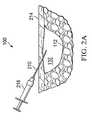
- FIGS. 2A-2Ddepict partial cross-sectional side views of a needle, guide wire, dilator, and sheath to assist in delivering the catheter of FIG. 1 to the tissue site;
- FIGS. 3A-3Dillustrate partial cross-sectional side views of a filament feeding system according to an illustrative embodiment, the filament feeding system being used to deliver the filament of FIG. 1 through the catheter to the tissue site;
- FIG. 4depicts a cross-sectional view of the catheter of FIG. 1 taken at 4 - 4 ;
- FIGS. 5A and 5Billustrate cross-sectional views of the catheter of FIG. 1 and embodiments showing how the filament may be pre-kinked or positioned prior to advancement through the catheter;
- FIG. 6depicts a method of promoting new tissue growth at a tissue site according to an illustrative embodiment.
- reduced pressuregenerally refers to a pressure less than the ambient pressure at a tissue site that is being subjected to treatment. In most cases, this reduced pressure will be less than the atmospheric pressure at which the patient is located. Alternatively, the reduced pressure may be less than a hydrostatic pressure associated with tissue at the tissue site. Although the terms “vacuum” and “negative pressure” may be used to describe the pressure applied to the tissue site, the actual pressure reduction applied to the tissue site may be significantly less than the pressure reduction normally associated with a complete vacuum. Reduced pressure may initially generate fluid flow in the area of the tissue site. As the hydrostatic pressure around the tissue site approaches the desired reduced pressure, the flow may subside, and the reduced pressure is then maintained. Unless otherwise indicated, values of pressure stated herein are gauge pressures. Similarly, references to increases in reduced pressure typically refer to a decrease in absolute pressure, while decreases in reduced pressure typically refer to an increase in absolute pressure.
- tissue siterefers to a wound or defect located on or within any tissue, including but not limited to, bone tissue, adipose tissue, muscle tissue, neural tissue, dermal tissue, vascular tissue, connective tissue, cartilage, tendons, or ligaments.
- tissue sitemay further refer to areas of any tissue that are not necessarily wounded or defective, but are instead areas in which it is desired to add or promote the growth of additional tissue. For example, reduced pressure tissue treatment may be used in certain tissue areas to grow additional tissue that may be harvested and transplanted to another tissue location.
- each lumenmay be single or multi-purpose.
- the lumensmay be part of simple catheters or other devices that can be advanced to the tissue site either separately or together.
- the lumens within a particular cathetermay be arranged parallel, skewed, or coaxial to one another.
- the cross-sectional shape of the lumensmay be circular or any non-circular shape.
- each lumenmay be used for venting or purging purposes, for filament delivery or removal, for lavage or other fluid delivery, or for delivery of suction or reduced pressure.
- each lumenmay include means for sealing against negative pressure such as a septum, plug or cap. Such means may include means to seal around filaments or other structures similar to those known in the hemostatic introducer art.
- a reduced pressure treatment system 100includes a filament delivery conduit 104 having a distal end 108 adapted to be positioned at a tissue site 112 of a patient 114 and a proximal end 116 that is positioned extracorporeal to the patient.
- a filament 120which in the embodiment illustrated in FIG. 1 is a single, continuous, elongated material, is positioned in the filament delivery conduit 104 such that one end 122 of the filament 120 extends from the proximal end 116 of the filament delivery conduit 104 and another end 124 of the filament 120 extends from the distal end 108 of the filament delivery conduit 104 .
- the filament 120may be discontinuous and include several separate and unconnected filaments that may be delivered to the tissue site 112 through the filament delivery conduit 104 .
- the filament delivery conduit 104provides a protected and preferably unobstructed pathway for the filament 120 to be delivered to the tissue site 112 .
- the filament 120forms into a filament mass 128 as the filament 120 is advanced through the filament conduit 104 .
- the filament mass 128is positioned adjacent the tissue site 112 .
- the tissue site 112is subcutaneous and a void 132 is present adjacent the tissue site 112 .
- the filament mass 128is positioned within the void 132 .
- the reduced pressure treatment system 100further includes a reduced pressure delivery conduit 136 that is adapted to fluidly communicate with a reduced pressure source 140 and the filament mass 128 such that a reduced pressure is delivered to the tissue site 112 through the filament mass 128 .
- both the reduced pressure delivery conduit 136 and the filament delivery conduit 104are part of a catheter 142 that may include one or more lumens.
- a distal portion 141 of the catheter 142may include a single lumen that is branched into separate lumens in proximal portions 143 of the catheter 142 at bifurcation 146 .
- separate lumensmay be provided in the distal portion 141 of the catheter 142 to keep separate the functions of each lumen.
- a cross-section of the distal portion 141illustrates three distinct and separate lumens 145 , 147 , and 149 , two of which are circular in cross-section and another of which is D-shaped in cross-section.
- Lumen 145may be used as the filament delivery conduit 104 to deliver the filament 120 to the tissue site 112 .
- Lumen 149may be used as the reduced pressure delivery conduit 136 to deliver reduced pressure to the tissue site.
- Lumen 147may be used either for venting or purging purposes, or for lavage or other fluid delivery.
- separate catheters having separate lumensmay be independently or simultaneously delivered to the tissue site to serve as the filament delivery conduit 104 and reduced pressure delivery conduit 136 .
- the catheters described hereinmay be constructed from any of a number of materials well known in the art, including without limitation polyethylene, nylon and nylon blends, polyurethane, vinyl, silicone and fluoropolymers.
- Catheter materialsmay be any materials with a Shore durometers of 30 A to 75 D.
- the catheter(s)will be made from Shore durometers of 80 A to 65 D, and in other embodiments from Shore 55 D to 65 D.
- the cathetersmay be coated with materials well known in the art.
- the internal lumenmay be coated with a hydrogel for reduced friction and/or heparin for reduced thrombogenicity.
- the exteriormay be coated with an antibiotic to reduce the risk of infection.
- the reduced pressure source 140is an electrically-driven vacuum pump.
- the reduced pressure source 140may instead be a manually-actuated or manually-charged pump that does not require electrical power, or any other type of reduced pressure pump.
- the reduced pressure source 140may be a wall suction port such as are available in hospitals and other medical facilities.
- the reduced pressure source 140may be housed within or used in conjunction with a reduced pressure treatment unit 144 , which may also contain sensors, processing units, alarm indicators, memory, databases, software, display units, and user interfaces that further facilitate the application of reduced pressure treatment to the tissue site 112 .
- a sensor or switchmay be disposed at or near the reduced pressure source 140 to determine a source pressure generated by the reduced pressure source 140 .
- the sensormay communicate with a processing unit that monitors and controls the reduced pressure that is delivered by the reduced pressure source 140 .
- a canister 148may be fluidly connected between the reduced pressure source 140 and the tissue site 112 to collect exudate and other fluids drawn from the tissue site 112 and void 132 by the reduced pressure source 140 .
- the filament 120may be constructed from bioresorbable materials that do not have to be removed from a patient's body following reduced pressure treatment.
- Suitable bioresorbable materialsmay include, without limitation, a polymeric blend of polylactic acid (PLA) and polyglycolic acid (PGA).
- the polymeric blendmay also include, without limitation, polycarbonates, polyfumarates, and capralactones.
- the filament 120 and filament mass 128may further serve as a scaffold for new cell-growth, or a scaffold material may be used in conjunction with the filament 120 to promote cell-growth.
- a scaffoldis a substance or structure used to enhance or promote the growth of cells or formation of tissue, such as a three-dimensional porous structure that provides a template for cell growth.
- scaffold materialsinclude calcium phosphate, collagen, PLA/PGA, coral hydroxy apatites, carbonates, or processed allograft materials.
- the filament 120may be constructed from a non-bioresorbable material. This material may be a monofilament, woven or braided. Suitable material may include, without limitation, polypropylene, polyester, fluoropolymers, polyurethanes and nylons.
- the filament mass 128 of the reduced pressure treatment system 100is a folded or tangled mass formed as the filament 120 is placed at the tissue site 112 . While the filament 120 could be placed within the void 132 in an orderly fashion causing the filament 120 to fold in a predictable manner, in most instances it is desirable to allow the filament 120 to randomly kink and fold as it is placed within the void 132 .
- the filament mass 128may be any size, shape, or thickness, but when used to treat a subcutaneous tissue site, the boundaries of the filament mass 128 are likely defined by the void 132 .
- the filament mass 128is adapted to contact the tissue site 112 .
- the filament mass 128may be partially or fully in contact with the tissue site 112 being treated. When the tissue site 112 is a wound, the filament mass 128 may partially or fully fill the wound.
- the filament mass 128acts as a distribution manifold, allowing reduced pressure to be distributed to the tissue site 112 through voids and other spaces that exist within the filament mass 128 . These voids and spaces are present in the filament mass 128 due to the loosely-packed nature of the filament 120 in the filament mass 128 . When the filament 120 is more tightly-packed, and thus has a greater “density” within the filament mass 128 , the volume of voids and spaces within the filament mass 128 is typically less. The volume of the voids and spaces can be increased or decreased depending on a particular tissue site and the amount of reduced pressure that is desired.
- the “density” of the filament masswill also affect the ability of the filament 120 to resist collapse of the void 132 when reduced pressure is applied. Since the void 132 is substantially sealed when reduced pressure is applied, the tissue surrounding the void 132 will typically approximate, resulting in a contraction of the void 132 . While some contraction is acceptable, the filament mass 128 may aid in preventing complete collapse of the void 132 , which allows continued distribution of reduced pressure to the tissue site 112 . When the filament mass 128 has a higher density, the filament mass 128 is better able to resist collapse of the void 132 .
- the filament mass 128also assists in promoting tissue growth at the tissue site 112 by inducing microstrain at the tissue site 112 .
- tissue site 112 and filament mass 128are pulled into closer contact with one another, which generates microstrain at the cellular level of the tissue site 112 as the tissue contacts the filaments 120 of the filament mass 128 .
- the kinks, twists, and folds of the filament 120 in the filament mass 128create corners and edges that better enable the filament mass to create microstrain at the tissue site 112 .
- a cover(not shown), or drape, may be positioned over the filament mass 128 and tissue site to maintain reduced pressure beneath the cover at the tissue site.
- the covermay extend beyond a perimeter of the tissue site and may include an adhesive or bonding agent on the cover to secure the cover to tissue adjacent the tissue site.
- a sealing layersuch as a hydrogel material may be positioned between the cover and the tissue to improve sealing of the cover at the tissue site.
- the use of a cover to seal the void 132 to maintain reduced pressure at the tissue site 112may not be necessary since the void 132 is substantially sealed from ambient by the presence of the patient's own tissue around the void 132 . It may be desired, however, to seal around the catheter 142 where the catheter enters the patient. Such sealing may be accomplished by positioning a drape or cover around the catheter 142 where the catheter 142 enters the patient's skin. Alternatively, a suture or adhesive may be placed in this location to better seal around the catheter 142 .
- the reduced pressure treatment system 100may include additional components to assist in guiding and delivering the filament 120 to the tissue site 112 .
- a needle 210is inserted through skin 214 of the patient and guided to the void 132 adjacent the tissue site 112 .
- the void 132may be located in or surrounded by any type of tissue beneath the skin 214 , thus, it may be required to guide the needle 210 through several layers or types of tissue.
- the advancement of the needle 210 to the void 132may be monitored or guided by ultrasound, x-ray, fluoroscopic guidance, or other monitoring or guidance techniques. While the needle 210 of FIG.
- a syringe 218is illustrated with a syringe 218 attached, the presence of the syringe 218 is optional. If a syringe 218 is attached to the needle 201 , the syringe 218 is preferably removed from the needle 210 after insertion to allow direct access to a lumen that passes through the needle 210 .
- a guide wire 222is advanced through the lumen of the needle 210 to the void 132 .
- the guide wire 222includes a common configuration of a core covered by a coil to provide additional flexibility.
- the guide wire 222may include a less flexible configuration, such as with a stylet or mandrel.
- the guide wire 222may be inserted into the lumen by a wire storage device 226 .
- the guide wiremay be monitored or guided by x-ray, fluoroscopic guidance, or other monitoring or guidance techniques. After delivering an end of the guide wire 222 to the void 132 , the needle 210 may be withdrawn from the void 132 and removed from the guide wire 222 .
- the stylet or mandrel style of guide wire 222may optionally be made of material of sufficient strength for the wire 222 to be pushed into and through tissues of the body.
- the interior diameter of the lumen of the needle 210 and the diameter of the guide wire 222are sized such that the guide wire 222 can be advanced through the needle 210 without any undue pressure caused by friction.
- the guide wirecan have sufficient stiffness to not require use of a needle.
- the distal tip of the guide wireincludes a sharp trocar or other style tip.
- a dilator 232 and a sheath 236may be advanced along the guide wire 222 to the void 132 . While illustrated together, the dilator 232 could be used separately to assist in dilating or dissecting tissue along the guide wire 222 to allow insertion of the sheath 236 , or in another embodiment, direct insertion of the catheter 142 .
- the dilator 232preferably includes a tapered tip 240 to assist in dilating tissue.
- the sheath 236is positioned coaxially over the dilator 232 and is advanced to the tissue site 112 simultaneously with the dilator 232 .
- the wall thickness of the sheath 236is relatively thin to prevent unnecessary dilation or damage to tissue as the dilator 232 and sheath 236 are inserted.
- the wall thickness of the sheath 236may in one embodiment be 0.020 inches or less.
- the catheter 142may be introduced to the void 132 by advancing the catheter 142 through a lumen of the sheath 236 .
- the sheath 236may be removed.
- the sheath 236is a peel or tear-away sheath that is capable of being split or torn apart from the catheter 142 after the sheath 236 is withdrawn from the patient.
- a medical professionalis able to more easily remove the sheath 236 from around the catheter 142 .
- the sheathmay be left in place to create an annular lumen between the sheath and catheter, to facilitate catheter exchange and/or to serve as a vacuum transmitting lumen after withdrawal of the filament delivery catheter.
- the reduced pressure treatment system 100may include a filament feeding system 312 .
- the filament feeding system 312includes a first tube 316 and a second tube 320 . Both the first tube 316 and the second tube 320 include passages through which the filament 120 may be advanced.
- the first tube 316includes an outer diameter that is slightly less than an inner diameter of the second tube 320 .
- a gripper member 324 having a passage 328is operably associated with the second tube 320 and is capable of being moved between an open position illustrated in FIG. 3A and a closed, or gripping, position illustrated in FIG. 3B .
- the size of the passage 328is such that the filament 120 is permitted to freely pass through the passage 328 .
- the size of the passage 328is such that the gripper member 324 grips the filament 120 and prevents free movement of the filament 120 through the passage 328 .
- diameters of lumensare selected to balance frictional resistance to advancement of a kinked fiber with the need to keep the fiber aligned with the axis of the lumen and avoid the fiber folding over within the lumen.
- the filament feeding system 312is arranged such that one end of the first tube 316 is placed within the passage of the second tube 320 .
- the filament 120is fed though the gripper passage 328 and through both the first tube 316 and the second tube 320 (see FIG. 3A ).
- the gripper member 324is then moved to the closed position to grip the filament 120 (see FIG. 3B ).
- the second tube 320is advanced along the first tube 316 by an advancement distance 332 . As the second tube 320 advances, the filament 120 also advances through the first tube 316 by the advancement distance 332 .
- the inner diameter of the first tube 316 and second tube 320is small enough and the stiffness of the filament 120 is great enough that the filament 120 is prevented from binding within the passages of the first and second tubes 316 , 320 .
- the gripper member 324is allowed to return to the open position, and the second tube 320 is retracted from the first tube 316 as illustrated in FIG. 3D .
- the filament 120remains stationary relative to the first tube 316 .
- the movement of the second tube 320 , gripper member 324 , and filament 120 as shown in FIGS. 3A-3Dis repeated to continue the advancement of the filament 120 .
- the first tube 316is a conduit separate from the catheter 142 that may be placed within the filament delivery conduit 104 or the catheter 104 to assist in advancing the filament 120 to the tissue site 112 .
- the first tube 316may be the catheter 142 with the passage or lumen of the catheter 142 being the filament delivery conduit 104 .
- the filament feeding system 312provides a quick and effective means of delivering the filament 120 to the tissue site 112
- the filament 120may be delivered to the tissue site 112 by any means convenient to the medical professional.
- the filament 120may be hand-fed or manually advanced through the filament delivery conduit 104 .
- a reelmay be attached to the proximal portion 143 of the catheter 142 to quickly dispense and deliver the filament 120 to the tissue site 112 .
- the catheter 142includes means for cutting the filament 120 after the filament 120 has been deployed at the tissue site 112 .
- Such meansmay include, for example, cutting edges or sharp edges located with the catheter 142 .
- the filament 120may be advanced to the tissue site 112 as a single, continuous filament.
- the filament 120may include multiple, individual filaments that may be advanced separately or simultaneously to the tissue site 112 .
- the filament 120may be pre-kinked before being advanced through the catheter 142 to facilitate the filament “balling” or “tangling” to form the filament mass 128 .
- Kinkingmay optionally include regular (repeating) or irregular (variable) patterns of kink orientation. Kinking may optionally be in a single plane or multi-planar. Once the filament 120 is pre-kinked, it may be advanced through the lumen of the catheter 142 , as illustrated in FIG. 5A .
- the diameters of the filament lumenis selected to balance frictional resistance to advancement of a kinked fiber with the need to keep the fiber aligned with the axis of the lumen and avoid the fiber folding over within the lumen. This is generally accomplished by maintaining lumen diameter to keep the angle between the filament and lumen wall at less than 45 degrees. A non-kinked filament will align substantially parallel with the lumen wall (effectively a 0 degree angle). As the filament 120 is released from the catheter 142 , the filament 120 relaxes to begin forming loops, zigzags, waves, crinkles, corkscrews, or other random shapes and positions as illustrated in FIG. 5B .
- the distal end of the filament 120may assume or be formed into a pigtail tip to avoid puncture of the tissue site walls, as illustrated in FIG. 5A .
- the kinks and turns in the filament 120facilitate the formation of the filament mass 128 by balling or tangling, to fill the void 132 as illustrated in FIG. 5B .
- a method 610 for promoting new tissue growth at a subcutaneous tissue site of a patientoptionally includes delivering a needle to the tissue site at 614 .
- the position of the needleis monitored until a tip of the needle reaches the tissue site.
- a guide wireis delivered through a lumen of the needle to the tissue site at 618 . If a needle is not used prior to insertion of the guide wire, a relatively stiff, pointed guide wire may be advanced directly to the tissue site. The placement and guidance of the guide wire may be monitored by the means described previously for monitoring the placement of the needle.
- a sheath and dilatorare advanced over the guide wire to the tissue site at 622 .
- the dilatoris removed, and a catheter is delivered through the sheath to the tissue site at 630 .
- a filamentmay be advanced, as illustrated at 634 , through a lumen of the catheter to the tissue site to form a filament mass at the tissue site.
- a reduced pressureis applied to the filament mass at the tissue site.
- the filamentmay be removed from the tissue site, as illustrated at 642 , or may be left at the tissue site to bioabsorb as illustrated at 646 .
Landscapes
- Health & Medical Sciences (AREA)
- Surgery (AREA)
- Life Sciences & Earth Sciences (AREA)
- Heart & Thoracic Surgery (AREA)
- Molecular Biology (AREA)
- Vascular Medicine (AREA)
- Engineering & Computer Science (AREA)
- Biomedical Technology (AREA)
- Reproductive Health (AREA)
- Medical Informatics (AREA)
- Nuclear Medicine, Radiotherapy & Molecular Imaging (AREA)
- Animal Behavior & Ethology (AREA)
- General Health & Medical Sciences (AREA)
- Public Health (AREA)
- Veterinary Medicine (AREA)
- Media Introduction/Drainage Providing Device (AREA)
- Surgical Instruments (AREA)
- External Artificial Organs (AREA)
- Infusion, Injection, And Reservoir Apparatuses (AREA)
Abstract
Description
Claims (24)
Priority Applications (1)
| Application Number | Priority Date | Filing Date | Title |
|---|---|---|---|
| US12/465,462US8372060B2 (en) | 2008-05-13 | 2009-05-13 | Catheter/filament style device and methods for treatment of wounds beneath the surface of the skin |
Applications Claiming Priority (2)
| Application Number | Priority Date | Filing Date | Title |
|---|---|---|---|
| US5286708P | 2008-05-13 | 2008-05-13 | |
| US12/465,462US8372060B2 (en) | 2008-05-13 | 2009-05-13 | Catheter/filament style device and methods for treatment of wounds beneath the surface of the skin |
Publications (2)
| Publication Number | Publication Date |
|---|---|
| US20090287181A1 US20090287181A1 (en) | 2009-11-19 |
| US8372060B2true US8372060B2 (en) | 2013-02-12 |
Family
ID=41037850
Family Applications (1)
| Application Number | Title | Priority Date | Filing Date |
|---|---|---|---|
| US12/465,462Active2031-02-01US8372060B2 (en) | 2008-05-13 | 2009-05-13 | Catheter/filament style device and methods for treatment of wounds beneath the surface of the skin |
Country Status (11)
| Country | Link |
|---|---|
| US (1) | US8372060B2 (en) |
| EP (2) | EP2274025B1 (en) |
| JP (1) | JP5290405B2 (en) |
| KR (1) | KR20110009693A (en) |
| CN (1) | CN102014981B (en) |
| AU (1) | AU2009246365B2 (en) |
| CA (1) | CA2723952C (en) |
| MX (1) | MX2010012366A (en) |
| RU (1) | RU2468827C2 (en) |
| TW (1) | TW200950839A (en) |
| WO (1) | WO2009140376A1 (en) |
Families Citing this family (37)
| Publication number | Priority date | Publication date | Assignee | Title |
|---|---|---|---|---|
| US11298453B2 (en) | 2003-10-28 | 2022-04-12 | Smith & Nephew Plc | Apparatus and method for wound cleansing with actives |
| GB0508531D0 (en) | 2005-04-27 | 2005-06-01 | Smith & Nephew | Sai with ultrasound |
| GB0723872D0 (en) | 2007-12-06 | 2008-01-16 | Smith & Nephew | Apparatus for topical negative pressure therapy |
| US8021347B2 (en) | 2008-07-21 | 2011-09-20 | Tyco Healthcare Group Lp | Thin film wound dressing |
| US8298200B2 (en) | 2009-06-01 | 2012-10-30 | Tyco Healthcare Group Lp | System for providing continual drainage in negative pressure wound therapy |
| ES2658263T3 (en) | 2008-08-08 | 2018-03-09 | Smith & Nephew, Inc. | Continuous fiber wound dressing |
| WO2010051071A1 (en) | 2008-10-29 | 2010-05-06 | Kci Licensing, Inc. | Reduced-pressure, wound-closure and treatment systems and methods |
| US8162907B2 (en) | 2009-01-20 | 2012-04-24 | Tyco Healthcare Group Lp | Method and apparatus for bridging from a dressing in negative pressure wound therapy |
| US20100324516A1 (en) | 2009-06-18 | 2010-12-23 | Tyco Healthcare Group Lp | Apparatus for Vacuum Bridging and/or Exudate Collection |
| AU2010341491B2 (en) | 2009-12-22 | 2015-05-14 | Smith & Nephew, Inc. | Apparatuses and methods for negative pressure wound therapy |
| USRE48117E1 (en) | 2010-05-07 | 2020-07-28 | Smith & Nephew, Inc. | Apparatuses and methods for negative pressure wound therapy |
| GB201011173D0 (en) | 2010-07-02 | 2010-08-18 | Smith & Nephew | Provision of wound filler |
| RU2016111981A (en) | 2010-12-22 | 2018-11-27 | Смит Энд Нефью, Инк. | DEVICE AND METHOD FOR TREATING RAS WITH NEGATIVE PRESSURE |
| MY162928A (en)* | 2011-03-23 | 2017-07-31 | E Yeung Jeffrey | Tissue repair with space-seeking spirals of filament |
| EP3851131A1 (en) | 2011-05-31 | 2021-07-21 | LifeCell Corporation | Adipose tissue matrices |
| JP6400570B2 (en) | 2012-05-23 | 2018-10-10 | スミス アンド ネフュー ピーエルシーSmith & Nephew Public Limited Company | Apparatus and method for local negative pressure closure therapy |
| AU2013289045B2 (en) | 2012-07-13 | 2017-02-16 | Lifecell Corporation | Methods for improved treatment of adipose tissue |
| CN108186200B (en) | 2012-08-01 | 2021-08-10 | 史密夫及内修公开有限公司 | Wound dressing |
| WO2014020440A1 (en) | 2012-08-01 | 2014-02-06 | Smith & Nephew Plc | Wound dressing |
| DE102012214640A1 (en) | 2012-08-17 | 2014-02-20 | Aesculap Ag | Flocked medical tube |
| US9370536B2 (en) | 2012-09-26 | 2016-06-21 | Lifecell Corporation | Processed adipose tissue |
| DE102013202849A1 (en) | 2013-02-21 | 2014-08-21 | Aesculap Ag | Medical product and medical kit for the derivation of pathological fluid collections |
| US10010658B2 (en) | 2013-05-10 | 2018-07-03 | Smith & Nephew Plc | Fluidic connector for irrigation and aspiration of wounds |
| US10286195B2 (en)* | 2014-03-19 | 2019-05-14 | University Of Maryland, Baltimore | Surgical drain sutured-in-place prevention device |
| US10076594B2 (en) | 2015-05-18 | 2018-09-18 | Smith & Nephew Plc | Fluidic connector for negative pressure wound therapy |
| EP3481446B1 (en) | 2016-07-05 | 2020-09-30 | LifeCell Corporation | Tissue matrices incorporating multiple tissue types |
| TWI629072B (en)* | 2017-01-13 | 2018-07-11 | 廈門聖慈醫療器材有限公司 | Suction disc |
| TWI621453B (en) | 2017-01-13 | 2018-04-21 | 廈門聖慈醫療器材有限公司 | Suction disc |
| JP7297739B2 (en) | 2017-10-18 | 2023-06-26 | ライフセル コーポレーション | Adipose tissue products and manufacturing methods |
| US11123375B2 (en) | 2017-10-18 | 2021-09-21 | Lifecell Corporation | Methods of treating tissue voids following removal of implantable infusion ports using adipose tissue products |
| AU2018351314A1 (en) | 2017-10-19 | 2020-03-19 | Lifecell Corporation | Flowable acellular tissue matrix products and methods of production |
| US11246994B2 (en) | 2017-10-19 | 2022-02-15 | Lifecell Corporation | Methods for introduction of flowable acellular tissue matrix products into a hand |
| GB201718014D0 (en) | 2017-11-01 | 2017-12-13 | Smith & Nephew | Dressing for negative pressure wound therapy with filter |
| GB201811449D0 (en) | 2018-07-12 | 2018-08-29 | Smith & Nephew | Apparatuses and methods for negative pressure wound therapy |
| EP3976127B1 (en) | 2019-05-30 | 2025-09-24 | LifeCell Corporation | Biologic breast implant |
| GB202000574D0 (en) | 2020-01-15 | 2020-02-26 | Smith & Nephew | Fluidic connectors for negative pressure wound therapy |
| JP2024518367A (en)* | 2021-05-06 | 2024-05-01 | ケーシーアイ マニュファクチャリング アンリミテッド カンパニー | Bioabsorbable, dispersible, rapidly deployable wound interface |
Citations (141)
| Publication number | Priority date | Publication date | Assignee | Title |
|---|---|---|---|---|
| US1355846A (en) | 1920-02-06 | 1920-10-19 | David A Rannells | Medical appliance |
| US2547758A (en) | 1949-01-05 | 1951-04-03 | Wilmer B Keeling | Instrument for treating the male urethra |
| US2632443A (en) | 1949-04-18 | 1953-03-24 | Eleanor P Lesher | Surgical dressing |
| GB692578A (en) | 1949-09-13 | 1953-06-10 | Minnesota Mining & Mfg | Improvements in or relating to drape sheets for surgical use |
| US2682873A (en) | 1952-07-30 | 1954-07-06 | Johnson & Johnson | General purpose protective dressing |
| US2910763A (en) | 1955-08-17 | 1959-11-03 | Du Pont | Felt-like products |
| US2969057A (en) | 1957-11-04 | 1961-01-24 | Brady Co W H | Nematodic swab |
| US3066672A (en) | 1960-09-27 | 1962-12-04 | Jr William H Crosby | Method and apparatus for serial sampling of intestinal juice |
| US3367332A (en) | 1965-08-27 | 1968-02-06 | Gen Electric | Product and process for establishing a sterile area of skin |
| US3520300A (en) | 1967-03-15 | 1970-07-14 | Amp Inc | Surgical sponge and suction device |
| US3568675A (en) | 1968-08-30 | 1971-03-09 | Clyde B Harvey | Fistula and penetrating wound dressing |
| US3648692A (en) | 1970-12-07 | 1972-03-14 | Parke Davis & Co | Medical-surgical dressing for burns and the like |
| US3682180A (en) | 1970-06-08 | 1972-08-08 | Coilform Co Inc | Drain clip for surgical drain |
| US3826254A (en) | 1973-02-26 | 1974-07-30 | Verco Ind | Needle or catheter retaining appliance |
| DE2640413A1 (en) | 1976-09-08 | 1978-03-09 | Wolf Gmbh Richard | CATHETER MONITORING DEVICE |
| US4080970A (en) | 1976-11-17 | 1978-03-28 | Miller Thomas J | Post-operative combination dressing and internal drain tube with external shield and tube connector |
| US4096853A (en) | 1975-06-21 | 1978-06-27 | Hoechst Aktiengesellschaft | Device for the introduction of contrast medium into an anus praeter |
| US4139004A (en) | 1977-02-17 | 1979-02-13 | Gonzalez Jr Harry | Bandage apparatus for treating burns |
| US4165748A (en) | 1977-11-07 | 1979-08-28 | Johnson Melissa C | Catheter tube holder |
| US4184510A (en) | 1977-03-15 | 1980-01-22 | Fibra-Sonics, Inc. | Valued device for controlling vacuum in surgery |
| US4233969A (en) | 1976-11-11 | 1980-11-18 | Lock Peter M | Wound dressing materials |
| US4245630A (en) | 1976-10-08 | 1981-01-20 | T. J. Smith & Nephew, Ltd. | Tearable composite strip of materials |
| US4256109A (en) | 1978-07-10 | 1981-03-17 | Nichols Robert L | Shut off valve for medical suction apparatus |
| US4261363A (en) | 1979-11-09 | 1981-04-14 | C. R. Bard, Inc. | Retention clips for body fluid drains |
| US4275721A (en) | 1978-11-28 | 1981-06-30 | Landstingens Inkopscentral Lic, Ekonomisk Forening | Vein catheter bandage |
| US4284079A (en) | 1979-06-28 | 1981-08-18 | Adair Edwin Lloyd | Method for applying a male incontinence device |
| US4297995A (en) | 1980-06-03 | 1981-11-03 | Key Pharmaceuticals, Inc. | Bandage containing attachment post |
| US4333468A (en) | 1980-08-18 | 1982-06-08 | Geist Robert W | Mesentery tube holder apparatus |
| US4373519A (en) | 1981-06-26 | 1983-02-15 | Minnesota Mining And Manufacturing Company | Composite wound dressing |
| US4382441A (en) | 1978-12-06 | 1983-05-10 | Svedman Paul | Device for treating tissues, for example skin |
| US4392858A (en) | 1981-07-16 | 1983-07-12 | Sherwood Medical Company | Wound drainage device |
| US4392853A (en) | 1981-03-16 | 1983-07-12 | Rudolph Muto | Sterile assembly for protecting and fastening an indwelling device |
| US4419097A (en) | 1981-07-31 | 1983-12-06 | Rexar Industries, Inc. | Attachment for catheter tube |
| EP0100148A1 (en) | 1982-07-06 | 1984-02-08 | Dow Corning Limited | Medical-surgical dressing and a process for the production thereof |
| US4465485A (en) | 1981-03-06 | 1984-08-14 | Becton, Dickinson And Company | Suction canister with unitary shut-off valve and filter features |
| EP0117632A2 (en) | 1983-01-27 | 1984-09-05 | Johnson & Johnson Products Inc. | Adhesive film dressing |
| US4475909A (en) | 1982-05-06 | 1984-10-09 | Eisenberg Melvin I | Male urinary device and method for applying the device |
| US4480638A (en) | 1980-03-11 | 1984-11-06 | Eduard Schmid | Cushion for holding an element of grafted skin |
| US4525374A (en) | 1984-02-27 | 1985-06-25 | Manresa, Inc. | Treating hydrophobic filters to render them hydrophilic |
| US4525166A (en) | 1981-11-21 | 1985-06-25 | Intermedicat Gmbh | Rolled flexible medical suction drainage device |
| US4540412A (en) | 1983-07-14 | 1985-09-10 | The Kendall Company | Device for moist heat therapy |
| US4543100A (en) | 1983-11-01 | 1985-09-24 | Brodsky Stuart A | Catheter and drain tube retainer |
| US4548202A (en) | 1983-06-20 | 1985-10-22 | Ethicon, Inc. | Mesh tissue fasteners |
| US4551139A (en) | 1982-02-08 | 1985-11-05 | Marion Laboratories, Inc. | Method and apparatus for burn wound treatment |
| EP0161865A2 (en) | 1984-05-03 | 1985-11-21 | Smith and Nephew Associated Companies p.l.c. | Adhesive wound dressing |
| US4569348A (en) | 1980-02-22 | 1986-02-11 | Velcro Usa Inc. | Catheter tube holder strap |
| US4578055A (en)* | 1979-07-25 | 1986-03-25 | Fischer Dan E | Controlled diffusion medicament applicator |
| US4605399A (en) | 1984-12-04 | 1986-08-12 | Complex, Inc. | Transdermal infusion device |
| US4608041A (en) | 1981-10-14 | 1986-08-26 | Frese Nielsen | Device for treatment of wounds in body tissue of patients by exposure to jets of gas |
| US4640688A (en) | 1985-08-23 | 1987-02-03 | Mentor Corporation | Urine collection catheter |
| US4655754A (en) | 1984-11-09 | 1987-04-07 | Stryker Corporation | Vacuum wound drainage system and lipids baffle therefor |
| US4664662A (en) | 1984-08-02 | 1987-05-12 | Smith And Nephew Associated Companies Plc | Wound dressing |
| US4710165A (en) | 1985-09-16 | 1987-12-01 | Mcneil Charles B | Wearable, variable rate suction/collection device |
| US4733659A (en) | 1986-01-17 | 1988-03-29 | Seton Company | Foam bandage |
| GB2195255A (en) | 1986-09-30 | 1988-04-07 | Vacutec Uk Limited | Method and apparatus for vacuum treatment of an epidermal surface |
| US4743232A (en) | 1986-10-06 | 1988-05-10 | The Clinipad Corporation | Package assembly for plastic film bandage |
| GB2197789A (en) | 1986-11-28 | 1988-06-02 | Smiths Industries Plc | Anti-foaming disinfectants used in surgical suction apparatus |
| US4758220A (en) | 1985-09-26 | 1988-07-19 | Alcon Laboratories, Inc. | Surgical cassette proximity sensing and latching apparatus |
| US4787888A (en) | 1987-06-01 | 1988-11-29 | University Of Connecticut | Disposable piezoelectric polymer bandage for percutaneous delivery of drugs and method for such percutaneous delivery (a) |
| US4826494A (en) | 1984-11-09 | 1989-05-02 | Stryker Corporation | Vacuum wound drainage system |
| US4838883A (en) | 1986-03-07 | 1989-06-13 | Nissho Corporation | Urine-collecting device |
| US4840187A (en) | 1986-09-11 | 1989-06-20 | Bard Limited | Sheath applicator |
| US4863449A (en) | 1987-07-06 | 1989-09-05 | Hollister Incorporated | Adhesive-lined elastic condom cathether |
| US4872450A (en) | 1984-08-17 | 1989-10-10 | Austad Eric D | Wound dressing and method of forming same |
| US4878901A (en) | 1986-10-10 | 1989-11-07 | Sachse Hans Ernst | Condom catheter, a urethral catheter for the prevention of ascending infections |
| GB2220357A (en) | 1988-05-28 | 1990-01-10 | Smiths Industries Plc | Medico-surgical containers |
| US4897081A (en) | 1984-05-25 | 1990-01-30 | Thermedics Inc. | Percutaneous access device |
| US4906240A (en) | 1988-02-01 | 1990-03-06 | Matrix Medica, Inc. | Adhesive-faced porous absorbent sheet and method of making same |
| US4906233A (en) | 1986-05-29 | 1990-03-06 | Terumo Kabushiki Kaisha | Method of securing a catheter body to a human skin surface |
| US4919654A (en) | 1988-08-03 | 1990-04-24 | Kalt Medical Corporation | IV clamp with membrane |
| CA2005436A1 (en) | 1988-12-13 | 1990-06-13 | Glenda G. Kalt | Transparent tracheostomy tube dressing |
| US4941882A (en) | 1987-03-14 | 1990-07-17 | Smith And Nephew Associated Companies, P.L.C. | Adhesive dressing for retaining a cannula on the skin |
| US4953565A (en) | 1986-11-26 | 1990-09-04 | Shunro Tachibana | Endermic application kits for external medicines |
| US4969880A (en) | 1989-04-03 | 1990-11-13 | Zamierowski David S | Wound dressing and treatment method |
| US4985019A (en) | 1988-03-11 | 1991-01-15 | Michelson Gary K | X-ray marker |
| GB2235877A (en) | 1989-09-18 | 1991-03-20 | Antonio Talluri | Closed wound suction apparatus |
| US5037397A (en) | 1985-05-03 | 1991-08-06 | Medical Distributors, Inc. | Universal clamp |
| US5061274A (en)* | 1989-12-04 | 1991-10-29 | Kensey Nash Corporation | Plug device for sealing openings and method of use |
| US5086170A (en) | 1989-01-16 | 1992-02-04 | Roussel Uclaf | Process for the preparation of azabicyclo compounds |
| US5090408A (en)* | 1985-10-18 | 1992-02-25 | Bryan T. Spofford | Transtracheal catheter system and method |
| US5092858A (en) | 1990-03-20 | 1992-03-03 | Becton, Dickinson And Company | Liquid gelling agent distributor device |
| US5100396A (en) | 1989-04-03 | 1992-03-31 | Zamierowski David S | Fluidic connection system and method |
| US5134994A (en) | 1990-02-12 | 1992-08-04 | Say Sam L | Field aspirator in a soft pack with externally mounted container |
| US5149331A (en) | 1991-05-03 | 1992-09-22 | Ariel Ferdman | Method and device for wound closure |
| US5167613A (en) | 1992-03-23 | 1992-12-01 | The Kendall Company | Composite vented wound dressing |
| US5176663A (en) | 1987-12-02 | 1993-01-05 | Pal Svedman | Dressing having pad with compressibility limiting elements |
| US5215522A (en) | 1984-07-23 | 1993-06-01 | Ballard Medical Products | Single use medical aspirating device and method |
| US5232453A (en) | 1989-07-14 | 1993-08-03 | E. R. Squibb & Sons, Inc. | Catheter holder |
| US5261893A (en) | 1989-04-03 | 1993-11-16 | Zamierowski David S | Fastening system and method |
| US5278100A (en) | 1991-11-08 | 1994-01-11 | Micron Technology, Inc. | Chemical vapor deposition technique for depositing titanium silicide on semiconductor wafers |
| US5279550A (en) | 1991-12-19 | 1994-01-18 | Gish Biomedical, Inc. | Orthopedic autotransfusion system |
| US5298015A (en) | 1989-07-11 | 1994-03-29 | Nippon Zeon Co., Ltd. | Wound dressing having a porous structure |
| US5342376A (en) | 1993-05-03 | 1994-08-30 | Dermagraphics, Inc. | Inserting device for a barbed tissue connector |
| US5344415A (en) | 1993-06-15 | 1994-09-06 | Deroyal Industries, Inc. | Sterile system for dressing vascular access site |
| DE4306478A1 (en) | 1993-03-02 | 1994-09-08 | Wolfgang Dr Wagner | Drainage device, in particular pleural drainage device, and drainage method |
| US5358494A (en) | 1989-07-11 | 1994-10-25 | Svedman Paul | Irrigation dressing |
| US5358492A (en)* | 1991-05-02 | 1994-10-25 | Feibus Miriam H | Woven surgical drain and method of making |
| US5431639A (en)* | 1993-08-12 | 1995-07-11 | Boston Scientific Corporation | Treating wounds caused by medical procedures |
| US5437651A (en) | 1993-09-01 | 1995-08-01 | Research Medical, Inc. | Medical suction apparatus |
| US5437622A (en) | 1992-04-29 | 1995-08-01 | Laboratoire Hydrex (Sa) | Transparent adhesive dressing with reinforced starter cuts |
| DE29504378U1 (en) | 1995-03-15 | 1995-09-14 | MTG Medizinisch, technische Gerätebau GmbH, 66299 Friedrichsthal | Electronically controlled low-vacuum pump for chest and wound drainage |
| US5478308A (en)* | 1992-04-02 | 1995-12-26 | New Dimensions In Medicine, Inc. | Wound packing and package therefor |
| US5527293A (en) | 1989-04-03 | 1996-06-18 | Kinetic Concepts, Inc. | Fastening system and method |
| US5549584A (en) | 1994-02-14 | 1996-08-27 | The Kendall Company | Apparatus for removing fluid from a wound |
| US5556375A (en) | 1994-06-16 | 1996-09-17 | Hercules Incorporated | Wound dressing having a fenestrated base layer |
| US5607388A (en) | 1994-06-16 | 1997-03-04 | Hercules Incorporated | Multi-purpose wound dressing |
| US5636643A (en) | 1991-11-14 | 1997-06-10 | Wake Forest University | Wound treatment employing reduced pressure |
| US5645081A (en) | 1991-11-14 | 1997-07-08 | Wake Forest University | Method of treating tissue damage and apparatus for same |
| US5885237A (en)* | 1993-10-05 | 1999-03-23 | Bristol-Myers Squibb Company | Trimmable wound dressing |
| GB2333965A (en) | 1997-09-12 | 1999-08-11 | Kci Medical Ltd | Surgical drape |
| US6071267A (en) | 1998-02-06 | 2000-06-06 | Kinetic Concepts, Inc. | Medical patient fluid management interface system and method |
| US6135116A (en) | 1997-07-28 | 2000-10-24 | Kci Licensing, Inc. | Therapeutic method for treating ulcers |
| US6241747B1 (en) | 1993-05-03 | 2001-06-05 | Quill Medical, Inc. | Barbed Bodily tissue connector |
| US6287316B1 (en) | 1999-03-26 | 2001-09-11 | Ethicon, Inc. | Knitted surgical mesh |
| US20020026244A1 (en)* | 2000-08-30 | 2002-02-28 | Trieu Hai H. | Intervertebral disc nucleus implants and methods |
| US20020077661A1 (en) | 2000-12-20 | 2002-06-20 | Vahid Saadat | Multi-barbed device for retaining tissue in apposition and methods of use |
| US20020115951A1 (en) | 2001-02-22 | 2002-08-22 | Core Products International, Inc. | Ankle brace providing upper and lower ankle adjustment |
| US20020120185A1 (en) | 2000-05-26 | 2002-08-29 | Kci Licensing, Inc. | System for combined transcutaneous blood gas monitoring and vacuum assisted wound closure |
| US20020143286A1 (en) | 2001-03-05 | 2002-10-03 | Kci Licensing, Inc. | Vacuum assisted wound treatment apparatus and infection identification system and method |
| US6488643B1 (en) | 1998-10-08 | 2002-12-03 | Kci Licensing, Inc. | Wound healing foot wrap |
| US6493568B1 (en) | 1994-07-19 | 2002-12-10 | Kci Licensing, Inc. | Patient interface system |
| AU755496B2 (en) | 1997-09-12 | 2002-12-12 | Kci Licensing, Inc. | Surgical drape and suction head for wound treatment |
| US6565544B1 (en)* | 2000-07-12 | 2003-05-20 | Rainin Edgar A | Blood removal device |
| US20040006311A1 (en)* | 2002-07-04 | 2004-01-08 | Semyon Shchervinsky | Drain catheters |
| US20040176745A1 (en)* | 2003-03-07 | 2004-09-09 | Scott Ferguson | Wound drain with elongated intermediate section of enhanced radial strength |
| US20050209574A1 (en)* | 2004-03-18 | 2005-09-22 | Boehringer Laboratories, Inc. | Wound packing material for use with suction |
| US20050240147A1 (en)* | 2004-04-21 | 2005-10-27 | Exploramed Ii, Inc. | Devices, systems and methods for diagnosing and treating sinusitus and other disorders of the ears, nose and/or throat |
| WO2006005939A1 (en) | 2004-07-09 | 2006-01-19 | Ethicon, Inc. | Vacuum wound dressings |
| US7182758B2 (en)* | 2003-11-17 | 2007-02-27 | Mccraw John B | Apparatus and method for drainage |
| US20070123816A1 (en)* | 2005-10-05 | 2007-05-31 | Zhu Yong H | Vascular wound closure device and method |
| WO2007105217A2 (en) | 2006-03-14 | 2007-09-20 | Thermopeutix Inc. | Aneurysm coil delivery system |
| US20070225738A1 (en) | 2006-03-24 | 2007-09-27 | Cook Incorporated | Aneurysm coil and method of assembly |
| US7318840B2 (en)* | 1999-12-06 | 2008-01-15 | Sdgi Holdings, Inc. | Intervertebral disc treatment devices and methods |
| US20080167593A1 (en)* | 2005-02-15 | 2008-07-10 | Wilhelm Fleischmann | Wound Treatment Device |
| JP4129536B2 (en) | 2000-02-24 | 2008-08-06 | ヴェネテック インターナショナル,インコーポレイテッド | Highly compatible catheter anchoring system |
| US20080188819A1 (en)* | 2006-07-07 | 2008-08-07 | Kloke Tim M | Beaded Wound Spacer Device |
| US20080281350A1 (en)* | 2006-12-13 | 2008-11-13 | Biomerix Corporation | Aneurysm Occlusion Devices |
| US7524315B2 (en)* | 2002-10-28 | 2009-04-28 | Smith & Nephew Plc | Apparatus for aspirating, irrigating and cleansing wounds |
| US20100036334A1 (en)* | 2008-08-08 | 2010-02-11 | Tyco Healthcare Group Lp | Wound Dressing of Continuous Fibers |
| US20100198171A1 (en)* | 1999-03-22 | 2010-08-05 | Spehalski Stephan R | Steerable wound drain device |
| US20110034906A1 (en)* | 2009-08-05 | 2011-02-10 | Tyco Healthcare Group Lp | Surgical Wound Dressing Incorporating Connected Hydrogel Beads Having an Embedded Electrode Therein |
Family Cites Families (1)
| Publication number | Priority date | Publication date | Assignee | Title |
|---|---|---|---|---|
| GB9926538D0 (en)* | 1999-11-09 | 2000-01-12 | Kci Medical Ltd | Multi-lumen connector |
- 2009
- 2009-05-13WOPCT/US2009/043778patent/WO2009140376A1/enactiveApplication Filing
- 2009-05-13JPJP2011509651Apatent/JP5290405B2/ennot_activeExpired - Fee Related
- 2009-05-13KRKR1020107027759Apatent/KR20110009693A/ennot_activeWithdrawn
- 2009-05-13CACA2723952Apatent/CA2723952C/ennot_activeExpired - Fee Related
- 2009-05-13CNCN200980115627.9Apatent/CN102014981B/ennot_activeExpired - Fee Related
- 2009-05-13EPEP09747460.5Apatent/EP2274025B1/enactiveActive
- 2009-05-13AUAU2009246365Apatent/AU2009246365B2/ennot_activeCeased
- 2009-05-13MXMX2010012366Apatent/MX2010012366A/enunknown
- 2009-05-13USUS12/465,462patent/US8372060B2/enactiveActive
- 2009-05-13EPEP11153649.6Apatent/EP2374486B1/enactiveActive
- 2009-05-13RURU2010143987/14Apatent/RU2468827C2/ennot_activeIP Right Cessation
- 2009-05-13TWTW098115917Apatent/TW200950839A/enunknown
Patent Citations (149)
| Publication number | Priority date | Publication date | Assignee | Title |
|---|---|---|---|---|
| US1355846A (en) | 1920-02-06 | 1920-10-19 | David A Rannells | Medical appliance |
| US2547758A (en) | 1949-01-05 | 1951-04-03 | Wilmer B Keeling | Instrument for treating the male urethra |
| US2632443A (en) | 1949-04-18 | 1953-03-24 | Eleanor P Lesher | Surgical dressing |
| GB692578A (en) | 1949-09-13 | 1953-06-10 | Minnesota Mining & Mfg | Improvements in or relating to drape sheets for surgical use |
| US2682873A (en) | 1952-07-30 | 1954-07-06 | Johnson & Johnson | General purpose protective dressing |
| US2910763A (en) | 1955-08-17 | 1959-11-03 | Du Pont | Felt-like products |
| US2969057A (en) | 1957-11-04 | 1961-01-24 | Brady Co W H | Nematodic swab |
| US3066672A (en) | 1960-09-27 | 1962-12-04 | Jr William H Crosby | Method and apparatus for serial sampling of intestinal juice |
| US3367332A (en) | 1965-08-27 | 1968-02-06 | Gen Electric | Product and process for establishing a sterile area of skin |
| US3520300A (en) | 1967-03-15 | 1970-07-14 | Amp Inc | Surgical sponge and suction device |
| US3568675A (en) | 1968-08-30 | 1971-03-09 | Clyde B Harvey | Fistula and penetrating wound dressing |
| US3682180A (en) | 1970-06-08 | 1972-08-08 | Coilform Co Inc | Drain clip for surgical drain |
| US3648692A (en) | 1970-12-07 | 1972-03-14 | Parke Davis & Co | Medical-surgical dressing for burns and the like |
| US3826254A (en) | 1973-02-26 | 1974-07-30 | Verco Ind | Needle or catheter retaining appliance |
| US4096853A (en) | 1975-06-21 | 1978-06-27 | Hoechst Aktiengesellschaft | Device for the introduction of contrast medium into an anus praeter |
| DE2640413A1 (en) | 1976-09-08 | 1978-03-09 | Wolf Gmbh Richard | CATHETER MONITORING DEVICE |
| US4245630A (en) | 1976-10-08 | 1981-01-20 | T. J. Smith & Nephew, Ltd. | Tearable composite strip of materials |
| US4233969A (en) | 1976-11-11 | 1980-11-18 | Lock Peter M | Wound dressing materials |
| US4080970A (en) | 1976-11-17 | 1978-03-28 | Miller Thomas J | Post-operative combination dressing and internal drain tube with external shield and tube connector |
| US4139004A (en) | 1977-02-17 | 1979-02-13 | Gonzalez Jr Harry | Bandage apparatus for treating burns |
| US4184510A (en) | 1977-03-15 | 1980-01-22 | Fibra-Sonics, Inc. | Valued device for controlling vacuum in surgery |
| US4165748A (en) | 1977-11-07 | 1979-08-28 | Johnson Melissa C | Catheter tube holder |
| US4256109A (en) | 1978-07-10 | 1981-03-17 | Nichols Robert L | Shut off valve for medical suction apparatus |
| US4275721A (en) | 1978-11-28 | 1981-06-30 | Landstingens Inkopscentral Lic, Ekonomisk Forening | Vein catheter bandage |
| US4382441A (en) | 1978-12-06 | 1983-05-10 | Svedman Paul | Device for treating tissues, for example skin |
| US4284079A (en) | 1979-06-28 | 1981-08-18 | Adair Edwin Lloyd | Method for applying a male incontinence device |
| US4578055A (en)* | 1979-07-25 | 1986-03-25 | Fischer Dan E | Controlled diffusion medicament applicator |
| US4261363A (en) | 1979-11-09 | 1981-04-14 | C. R. Bard, Inc. | Retention clips for body fluid drains |
| US4569348A (en) | 1980-02-22 | 1986-02-11 | Velcro Usa Inc. | Catheter tube holder strap |
| US4480638A (en) | 1980-03-11 | 1984-11-06 | Eduard Schmid | Cushion for holding an element of grafted skin |
| US4297995A (en) | 1980-06-03 | 1981-11-03 | Key Pharmaceuticals, Inc. | Bandage containing attachment post |
| US4333468A (en) | 1980-08-18 | 1982-06-08 | Geist Robert W | Mesentery tube holder apparatus |
| US4465485A (en) | 1981-03-06 | 1984-08-14 | Becton, Dickinson And Company | Suction canister with unitary shut-off valve and filter features |
| US4392853A (en) | 1981-03-16 | 1983-07-12 | Rudolph Muto | Sterile assembly for protecting and fastening an indwelling device |
| US4373519A (en) | 1981-06-26 | 1983-02-15 | Minnesota Mining And Manufacturing Company | Composite wound dressing |
| US4392858A (en) | 1981-07-16 | 1983-07-12 | Sherwood Medical Company | Wound drainage device |
| US4419097A (en) | 1981-07-31 | 1983-12-06 | Rexar Industries, Inc. | Attachment for catheter tube |
| US4608041A (en) | 1981-10-14 | 1986-08-26 | Frese Nielsen | Device for treatment of wounds in body tissue of patients by exposure to jets of gas |
| US4525166A (en) | 1981-11-21 | 1985-06-25 | Intermedicat Gmbh | Rolled flexible medical suction drainage device |
| US4551139A (en) | 1982-02-08 | 1985-11-05 | Marion Laboratories, Inc. | Method and apparatus for burn wound treatment |
| US4475909A (en) | 1982-05-06 | 1984-10-09 | Eisenberg Melvin I | Male urinary device and method for applying the device |
| EP0100148A1 (en) | 1982-07-06 | 1984-02-08 | Dow Corning Limited | Medical-surgical dressing and a process for the production thereof |
| EP0117632A2 (en) | 1983-01-27 | 1984-09-05 | Johnson & Johnson Products Inc. | Adhesive film dressing |
| US4548202A (en) | 1983-06-20 | 1985-10-22 | Ethicon, Inc. | Mesh tissue fasteners |
| US4540412A (en) | 1983-07-14 | 1985-09-10 | The Kendall Company | Device for moist heat therapy |
| US4543100A (en) | 1983-11-01 | 1985-09-24 | Brodsky Stuart A | Catheter and drain tube retainer |
| US4525374A (en) | 1984-02-27 | 1985-06-25 | Manresa, Inc. | Treating hydrophobic filters to render them hydrophilic |
| EP0161865A2 (en) | 1984-05-03 | 1985-11-21 | Smith and Nephew Associated Companies p.l.c. | Adhesive wound dressing |
| US4897081A (en) | 1984-05-25 | 1990-01-30 | Thermedics Inc. | Percutaneous access device |
| US5215522A (en) | 1984-07-23 | 1993-06-01 | Ballard Medical Products | Single use medical aspirating device and method |
| US4664662A (en) | 1984-08-02 | 1987-05-12 | Smith And Nephew Associated Companies Plc | Wound dressing |
| US4872450A (en) | 1984-08-17 | 1989-10-10 | Austad Eric D | Wound dressing and method of forming same |
| US4655754A (en) | 1984-11-09 | 1987-04-07 | Stryker Corporation | Vacuum wound drainage system and lipids baffle therefor |
| US4826494A (en) | 1984-11-09 | 1989-05-02 | Stryker Corporation | Vacuum wound drainage system |
| US4605399A (en) | 1984-12-04 | 1986-08-12 | Complex, Inc. | Transdermal infusion device |
| US5037397A (en) | 1985-05-03 | 1991-08-06 | Medical Distributors, Inc. | Universal clamp |
| US4640688A (en) | 1985-08-23 | 1987-02-03 | Mentor Corporation | Urine collection catheter |
| US4710165A (en) | 1985-09-16 | 1987-12-01 | Mcneil Charles B | Wearable, variable rate suction/collection device |
| US4758220A (en) | 1985-09-26 | 1988-07-19 | Alcon Laboratories, Inc. | Surgical cassette proximity sensing and latching apparatus |
| US5090408A (en)* | 1985-10-18 | 1992-02-25 | Bryan T. Spofford | Transtracheal catheter system and method |
| US4733659A (en) | 1986-01-17 | 1988-03-29 | Seton Company | Foam bandage |
| US4838883A (en) | 1986-03-07 | 1989-06-13 | Nissho Corporation | Urine-collecting device |
| US4906233A (en) | 1986-05-29 | 1990-03-06 | Terumo Kabushiki Kaisha | Method of securing a catheter body to a human skin surface |
| US4840187A (en) | 1986-09-11 | 1989-06-20 | Bard Limited | Sheath applicator |
| GB2195255A (en) | 1986-09-30 | 1988-04-07 | Vacutec Uk Limited | Method and apparatus for vacuum treatment of an epidermal surface |
| US4743232A (en) | 1986-10-06 | 1988-05-10 | The Clinipad Corporation | Package assembly for plastic film bandage |
| US4878901A (en) | 1986-10-10 | 1989-11-07 | Sachse Hans Ernst | Condom catheter, a urethral catheter for the prevention of ascending infections |
| US4953565A (en) | 1986-11-26 | 1990-09-04 | Shunro Tachibana | Endermic application kits for external medicines |
| GB2197789A (en) | 1986-11-28 | 1988-06-02 | Smiths Industries Plc | Anti-foaming disinfectants used in surgical suction apparatus |
| US4941882A (en) | 1987-03-14 | 1990-07-17 | Smith And Nephew Associated Companies, P.L.C. | Adhesive dressing for retaining a cannula on the skin |
| US4787888A (en) | 1987-06-01 | 1988-11-29 | University Of Connecticut | Disposable piezoelectric polymer bandage for percutaneous delivery of drugs and method for such percutaneous delivery (a) |
| US4863449A (en) | 1987-07-06 | 1989-09-05 | Hollister Incorporated | Adhesive-lined elastic condom cathether |
| US5176663A (en) | 1987-12-02 | 1993-01-05 | Pal Svedman | Dressing having pad with compressibility limiting elements |
| US4906240A (en) | 1988-02-01 | 1990-03-06 | Matrix Medica, Inc. | Adhesive-faced porous absorbent sheet and method of making same |
| US4985019A (en) | 1988-03-11 | 1991-01-15 | Michelson Gary K | X-ray marker |
| GB2220357A (en) | 1988-05-28 | 1990-01-10 | Smiths Industries Plc | Medico-surgical containers |
| EP0358302A2 (en) | 1988-05-28 | 1990-03-14 | Smiths Industries Public Limited Company | Medico-surgical suction container |
| US4919654A (en) | 1988-08-03 | 1990-04-24 | Kalt Medical Corporation | IV clamp with membrane |
| CA2005436A1 (en) | 1988-12-13 | 1990-06-13 | Glenda G. Kalt | Transparent tracheostomy tube dressing |
| US5086170A (en) | 1989-01-16 | 1992-02-04 | Roussel Uclaf | Process for the preparation of azabicyclo compounds |
| US5100396A (en) | 1989-04-03 | 1992-03-31 | Zamierowski David S | Fluidic connection system and method |
| US5527293A (en) | 1989-04-03 | 1996-06-18 | Kinetic Concepts, Inc. | Fastening system and method |
| US5261893A (en) | 1989-04-03 | 1993-11-16 | Zamierowski David S | Fastening system and method |
| US4969880A (en) | 1989-04-03 | 1990-11-13 | Zamierowski David S | Wound dressing and treatment method |
| US5298015A (en) | 1989-07-11 | 1994-03-29 | Nippon Zeon Co., Ltd. | Wound dressing having a porous structure |
| US5358494A (en) | 1989-07-11 | 1994-10-25 | Svedman Paul | Irrigation dressing |
| US5232453A (en) | 1989-07-14 | 1993-08-03 | E. R. Squibb & Sons, Inc. | Catheter holder |
| GB2235877A (en) | 1989-09-18 | 1991-03-20 | Antonio Talluri | Closed wound suction apparatus |
| US5061274A (en)* | 1989-12-04 | 1991-10-29 | Kensey Nash Corporation | Plug device for sealing openings and method of use |
| US5134994A (en) | 1990-02-12 | 1992-08-04 | Say Sam L | Field aspirator in a soft pack with externally mounted container |
| US5092858A (en) | 1990-03-20 | 1992-03-03 | Becton, Dickinson And Company | Liquid gelling agent distributor device |
| US5358492A (en)* | 1991-05-02 | 1994-10-25 | Feibus Miriam H | Woven surgical drain and method of making |
| US5149331A (en) | 1991-05-03 | 1992-09-22 | Ariel Ferdman | Method and device for wound closure |
| US5278100A (en) | 1991-11-08 | 1994-01-11 | Micron Technology, Inc. | Chemical vapor deposition technique for depositing titanium silicide on semiconductor wafers |
| US5645081A (en) | 1991-11-14 | 1997-07-08 | Wake Forest University | Method of treating tissue damage and apparatus for same |
| US5636643A (en) | 1991-11-14 | 1997-06-10 | Wake Forest University | Wound treatment employing reduced pressure |
| US5279550A (en) | 1991-12-19 | 1994-01-18 | Gish Biomedical, Inc. | Orthopedic autotransfusion system |
| US5167613A (en) | 1992-03-23 | 1992-12-01 | The Kendall Company | Composite vented wound dressing |
| US5478308A (en)* | 1992-04-02 | 1995-12-26 | New Dimensions In Medicine, Inc. | Wound packing and package therefor |
| US5437622A (en) | 1992-04-29 | 1995-08-01 | Laboratoire Hydrex (Sa) | Transparent adhesive dressing with reinforced starter cuts |
| DE4306478A1 (en) | 1993-03-02 | 1994-09-08 | Wolfgang Dr Wagner | Drainage device, in particular pleural drainage device, and drainage method |
| US5342376A (en) | 1993-05-03 | 1994-08-30 | Dermagraphics, Inc. | Inserting device for a barbed tissue connector |
| US6241747B1 (en) | 1993-05-03 | 2001-06-05 | Quill Medical, Inc. | Barbed Bodily tissue connector |
| US5344415A (en) | 1993-06-15 | 1994-09-06 | Deroyal Industries, Inc. | Sterile system for dressing vascular access site |
| US5431639A (en)* | 1993-08-12 | 1995-07-11 | Boston Scientific Corporation | Treating wounds caused by medical procedures |
| US5437651A (en) | 1993-09-01 | 1995-08-01 | Research Medical, Inc. | Medical suction apparatus |
| US5885237A (en)* | 1993-10-05 | 1999-03-23 | Bristol-Myers Squibb Company | Trimmable wound dressing |
| US5549584A (en) | 1994-02-14 | 1996-08-27 | The Kendall Company | Apparatus for removing fluid from a wound |
| US5556375A (en) | 1994-06-16 | 1996-09-17 | Hercules Incorporated | Wound dressing having a fenestrated base layer |
| US5607388A (en) | 1994-06-16 | 1997-03-04 | Hercules Incorporated | Multi-purpose wound dressing |
| US6493568B1 (en) | 1994-07-19 | 2002-12-10 | Kci Licensing, Inc. | Patient interface system |
| DE29504378U1 (en) | 1995-03-15 | 1995-09-14 | MTG Medizinisch, technische Gerätebau GmbH, 66299 Friedrichsthal | Electronically controlled low-vacuum pump for chest and wound drainage |
| US6135116A (en) | 1997-07-28 | 2000-10-24 | Kci Licensing, Inc. | Therapeutic method for treating ulcers |
| GB2329127B (en) | 1997-09-12 | 2000-08-16 | Kci Medical Ltd | Surgical drape and suction head for wound treatment |
| EP1018967B1 (en) | 1997-09-12 | 2004-08-18 | KCI Licensing, Inc. | Suction head for wound treatment and combination with a surgical drape |
| US6814079B2 (en) | 1997-09-12 | 2004-11-09 | Kci Licensing, Inc. | Surgical drape and suction head for wound treatment |
| US6345623B1 (en) | 1997-09-12 | 2002-02-12 | Keith Patrick Heaton | Surgical drape and suction head for wound treatment |
| US6553998B2 (en) | 1997-09-12 | 2003-04-29 | Kci Licensing, Inc. | Surgical drape and suction head for wound treatment |
| AU745271B2 (en) | 1997-09-12 | 2002-03-14 | Kci Licensing, Inc. | Surgical drape and suction head for wound treatment |
| AU755496B2 (en) | 1997-09-12 | 2002-12-12 | Kci Licensing, Inc. | Surgical drape and suction head for wound treatment |
| GB2333965A (en) | 1997-09-12 | 1999-08-11 | Kci Medical Ltd | Surgical drape |
| US6071267A (en) | 1998-02-06 | 2000-06-06 | Kinetic Concepts, Inc. | Medical patient fluid management interface system and method |
| US6488643B1 (en) | 1998-10-08 | 2002-12-03 | Kci Licensing, Inc. | Wound healing foot wrap |
| US20100198171A1 (en)* | 1999-03-22 | 2010-08-05 | Spehalski Stephan R | Steerable wound drain device |
| US6287316B1 (en) | 1999-03-26 | 2001-09-11 | Ethicon, Inc. | Knitted surgical mesh |
| US7318840B2 (en)* | 1999-12-06 | 2008-01-15 | Sdgi Holdings, Inc. | Intervertebral disc treatment devices and methods |
| JP4129536B2 (en) | 2000-02-24 | 2008-08-06 | ヴェネテック インターナショナル,インコーポレイテッド | Highly compatible catheter anchoring system |
| US20020120185A1 (en) | 2000-05-26 | 2002-08-29 | Kci Licensing, Inc. | System for combined transcutaneous blood gas monitoring and vacuum assisted wound closure |
| US6565544B1 (en)* | 2000-07-12 | 2003-05-20 | Rainin Edgar A | Blood removal device |
| US20020026244A1 (en)* | 2000-08-30 | 2002-02-28 | Trieu Hai H. | Intervertebral disc nucleus implants and methods |
| US20020077661A1 (en) | 2000-12-20 | 2002-06-20 | Vahid Saadat | Multi-barbed device for retaining tissue in apposition and methods of use |
| US20020115951A1 (en) | 2001-02-22 | 2002-08-22 | Core Products International, Inc. | Ankle brace providing upper and lower ankle adjustment |
| US20020143286A1 (en) | 2001-03-05 | 2002-10-03 | Kci Licensing, Inc. | Vacuum assisted wound treatment apparatus and infection identification system and method |
| US20040006311A1 (en)* | 2002-07-04 | 2004-01-08 | Semyon Shchervinsky | Drain catheters |
| US7524315B2 (en)* | 2002-10-28 | 2009-04-28 | Smith & Nephew Plc | Apparatus for aspirating, irrigating and cleansing wounds |
| US20040176745A1 (en)* | 2003-03-07 | 2004-09-09 | Scott Ferguson | Wound drain with elongated intermediate section of enhanced radial strength |
| US7182758B2 (en)* | 2003-11-17 | 2007-02-27 | Mccraw John B | Apparatus and method for drainage |
| US7754937B2 (en)* | 2004-03-18 | 2010-07-13 | Boehringer Technologies, L.P. | Wound packing material for use with suction |
| US20050209574A1 (en)* | 2004-03-18 | 2005-09-22 | Boehringer Laboratories, Inc. | Wound packing material for use with suction |
| US20050240147A1 (en)* | 2004-04-21 | 2005-10-27 | Exploramed Ii, Inc. | Devices, systems and methods for diagnosing and treating sinusitus and other disorders of the ears, nose and/or throat |
| WO2006005939A1 (en) | 2004-07-09 | 2006-01-19 | Ethicon, Inc. | Vacuum wound dressings |
| US20080167593A1 (en)* | 2005-02-15 | 2008-07-10 | Wilhelm Fleischmann | Wound Treatment Device |
| US20070123816A1 (en)* | 2005-10-05 | 2007-05-31 | Zhu Yong H | Vascular wound closure device and method |
| WO2007105217A2 (en) | 2006-03-14 | 2007-09-20 | Thermopeutix Inc. | Aneurysm coil delivery system |
| US20070225738A1 (en) | 2006-03-24 | 2007-09-27 | Cook Incorporated | Aneurysm coil and method of assembly |
| US20080188819A1 (en)* | 2006-07-07 | 2008-08-07 | Kloke Tim M | Beaded Wound Spacer Device |
| US20080281350A1 (en)* | 2006-12-13 | 2008-11-13 | Biomerix Corporation | Aneurysm Occlusion Devices |
| US20100036334A1 (en)* | 2008-08-08 | 2010-02-11 | Tyco Healthcare Group Lp | Wound Dressing of Continuous Fibers |
| US20110034906A1 (en)* | 2009-08-05 | 2011-02-10 | Tyco Healthcare Group Lp | Surgical Wound Dressing Incorporating Connected Hydrogel Beads Having an Embedded Electrode Therein |
Non-Patent Citations (41)
| Title |
|---|
| A.A. Safronov, Dissertation Abstract, Vacuum Therapy of Trophic Ulcers of the Lower Leg with Simultaneous Autoplasty of the Skin (Central Scientific Research Institute of Traumatology and Orthopedics, Moscow, U.S.S.R. 1967). |
| Arnljots, Björn et al.: "Irrigation Treatment in Split-Thickness Skin Grafting of Intractable Leg Ulcers", Scand J. Plast Reconstr. Surg., No. 19, 1985, pp. 211-213. |
| C.E. Tennants, "The Use of Hypermia in the Postoperative Treatment of Lesions of the Extremities and Thorax," Journal of the American Medical Association 64 (1915), pp. 1548-1549. |
| Chariker, Mark E., M.D., et al; "Effective Management of incisional and cutaneous fistulae with closed suction wound drainage"; Contemporary Surgery, vol. 34, Jun. 1989, pp. 59-63. |
| Chinn, Steven D. et al.: "Closed Wound Suction Drainage", The Journal of Foot Surgery, vol. 24, No. 1, 1985, pp. 76-81. |
| D.E. Tribble, An Improved Sump Drain-Irrigation Device of Simple Construction, Archives of Surgery 105 (1972) pp. 511-513. |
| Dattilo, Philip P., Jr., et al; "Medical Textiles: Application of an Absorbable Barbed Bi-directional Surgical Suture"; Journal of Textile and Apparel, Technology and Management, vol. 2, Issue 2, Spring 2002, pp. 1-5. |
| Davydov, Yu. A., et al; "Bacteriological and Cytological Assessment of Vacuum Therapy for Purulent Wounds"; Vestnik Khirurgi, Oct. 1988, pp. 48-52, and 8 page English translation thereof. |
| Davydov, Yu. A., et al; "Concepts for the Clinical-Biological Management of the Wound Process in the Treatment of Purulent Wounds by Means of Vacuum Therapy"; Vestnik Khirurgi, Jul. 7, 1980, pp. 132-136, and 8 page English translation thereof. |
| Davydov, Yu. A., et al; "Vacuum Therapy in the Treatment of Purulent Lactation Mastitis"; Vestnik Khirurgi, May 14, 1986, pp. 66-70, and 9 page English translation thereof. |
| Egnell Minor, Instruction Book, First Edition, 300 7502, Feb. 1975, pp. 24. |
| Egnell Minor: Addition to the Users Manual Concerning Overflow Protection-Concerns all Egnell Pumps, Feb. 3, 1983, pp. 2. |
| F.E. Johnson, "An Improved Technique for Skin Graft Placement Using a Suction Drain," Surgery, Gynecology, and Obstetrics 159 (1984), pp. 584-585. |
| G. {hacek over (Z)}ivadinovic, V. ukic, {hacek over (Z)}. Maksimovic, . Radak, and P. Pe{hacek over (s)}ka, "Vacuum Therapy in the Treatment of Peripheral Blood Vessels," Timok Medical Journal 11 (1986), pp. 161-164. |
| G. {hacek over (Z)}ivadinović, V. ukić, {hacek over (Z)}. Maksimović, . Radak, and P. Pe{hacek over (s)}ka, "Vacuum Therapy in the Treatment of Peripheral Blood Vessels," Timok Medical Journal 11 (1986), pp. 161-164. |
| George V. Letsou, MD., et al; "Stimulation of Adenylate Cyclase Activity in Cultured Endothelial Cells Subjected to Cyclic Stretch"; Journal of Cardiovascular Surgery, 31, 1990, pp. 634-639. |
| International Search Report and Written Opinion date mailed Sep. 18, 2009; PCT International Application No. PCT/US2009/043778. |
| International Search Report for PCT International Application PCT/GB95/01983; Nov. 23, 1995. |
| James H. Blackburn, II, MD, et al; "Negative-Pressure Dressings as a Bolster for Skin Grafts"; Annals of Plastic Surgery, vol. 40, No. 5, May 1998, pp. 453-457. |
| John Masters; "Reliable, Inexpensive and Simple Suction Dressings"; Letter to the Editor, British Journal of Plastic Surgery, 1998, vol. 51 (3), p. 267; Elsevier Science/The British Association of Plastic Surgeons, UK. |
| K.F. Jeter, T.E. Tintle, and M. Chariker, "Managing Draining Wounds and Fistulae: New and Established Methods," Chronic Wound Care, edited by D. Krasner (Health Management Publications, Inc., King of Prussia, PA 1990), pp. 240-246. |
| Kostyuchenok, B.M., et al; "Vacuum Treatment in the Surgical Management of Purulent Wounds"; Vestnik Khirurgi, Sep. 1986, pp. 18-21 and 6 page English translation thereof. |
| Louis C. Argenta, MD and Michael J. Morykwas, PhD; "Vacuum-Assisted Closure: A New Method for Wound Control and Treatment: Clinical Experience"; Annals of Plastic Surgery, vol. 38, No. 6, Jun. 1997; pp. 563-576. |
| M. Schein, R. Saadia, J.R. Jamieson, and G.A.G. Decker, "The 'Sandwich Technique' in the Management of the Open Abdomen," British Journal of Surgery 73 (1986), pp. 369-370. |
| M.J. Morykwas, L.C. Argenta, E.I. Shelton-Brown, and W. McGuirt, "Vacuum-Assisted Closure: A New Method for Wound Control and Treatment: Animal Studies and Basic Foundation," Annals of Plastic Surgery 38 (1997), pp. 553-562 (Morykwas I). |
| N.A. Bagautdinov, "Variant of External Vacuum Aspiration in the Treatment of Purulent Diseases of the Soft Tissues," Current Problems in Modern Clinical Surgery: Interdepartmental Collection, edited by V. Ye Volkov et al. (Chuvashia State University, Cheboksary, U.S.S.R. 1986);pp. 94-96. |
| Orringer, Jay, et al; "Management of Wounds in Patients with Complex Enterocutaneous Fistulas"; Surgery, Gynecology & Obstetrics, Jul. 1987, vol. 165, pp. 79-80. |
| PCT International Examination and Search Report, PCT International Application PCT/GB96/02802; Jan. 15, 1998 & Apr. 29, 1997. |
| PCT International Search Report for PCT International Application PCT/GB98/02713; Jan. 8, 1999. |
| PCT Written Opinion, PCT International Application PCT/GB96/02802; Sep. 3, 1997. |
| PCT Written Opinion; PCT International Application PCT/GB98/02713; Jun. 8, 1999. |
| S.E. Greer, et al "The Use of Subatmospheric Pressure Dressing Therapy to Close Lymphocutaneous Fistulas of the Groin" British Journal of Plastic Surgery (2000), 53, pp. 484-487. |
| Selections from W. Meyer and V. Schmieden, Bier's Hyperemic Treatment in Surgery, Medicine, and the Specialties: A Manual of Its Practical Application, (W.B. Saunders Co., Philadelphia, PA 1909), pp. 17-25, 44-64, 90-96, 167-170, and 210-211. |
| Susan Mendez-Eastmen, RN; "When Wounds Won't Heal" RN Jan. 1998, vol. 61 (1); Medical Economics Company, Inc., Montvale, NJ, USA; pp. 20-24. |
| Svedman, P. et al.: "A Dressing System Providing Fluid Supply and Suction Drainage Used for Continuous or Intermittent Irrigation", Annals of Plastic Surgery, vol. 17, No. 2, Aug. 1986, pp. 125-133. |
| Svedman, P.: "A Dressing Allowing Continuous Treatment of a Biosurface", IRCS Medical Science: Biomedical Technology, Clinical Medicine, Surgery and Transplantation, vol. 7, 1979, p. 221. |
| Svedman, P.: "Irrigation Treatment of Leg Ulcers", The Lancet, Sep. 3, 1983, pp. 532-534. |
| V.A. Kuznetsov & N.A. Bagautdinov, "Vacuum and Vacuum-Sorption Treatment of Open Septic Wounds," in II All-Union Conference on Wounds and Wound Infections: Presentation Abstracts, edited by B.M. Kostyuchenok et al. (Moscow, U.S.S.R. Oct. 28-29, 1986) pp. 91-92 ("Bagautdinov II"). |
| V.A. Solovev et al., Guidelines, The Method of Treatment of Immature External Fistulas in the Upper Gastrointestinal Tract, editor-in-chief Prov. V.I. Parahonyak (S.M. Kirov Gorky State Medical Institute, Gorky, U.S.S.R. 1987) ("Solovev Guidelines"). |
| V.A. Solovev, Dissertation Abstract, Treatment and Prevention of Suture Failures after Gastric Resection (S.M. Kirov Gorky State Medical Institute, Gorky, U.S.S.R. 1988) ("Solovev Abstract"). |
| Yusupov. Yu. N., et al; "Active Wound Drainage", Vestnik Khirurgi, vol. 138, Issue 4, 1987, and 7 page English translation thereof. |
Also Published As
| Publication number | Publication date |
|---|---|
| EP2274025A1 (en) | 2011-01-19 |
| JP5290405B2 (en) | 2013-09-18 |
| CN102014981A (en) | 2011-04-13 |
| WO2009140376A1 (en) | 2009-11-19 |
| EP2374486A1 (en) | 2011-10-12 |
| MX2010012366A (en) | 2011-02-24 |
| US20090287181A1 (en) | 2009-11-19 |
| JP2011520519A (en) | 2011-07-21 |
| CN102014981B (en) | 2014-04-23 |
| TW200950839A (en) | 2009-12-16 |
| KR20110009693A (en) | 2011-01-28 |
| RU2010143987A (en) | 2012-06-20 |
| AU2009246365B2 (en) | 2015-04-16 |
| CA2723952A1 (en) | 2009-11-19 |
| EP2374486B1 (en) | 2018-11-07 |
| AU2009246365A1 (en) | 2009-11-19 |
| RU2468827C2 (en) | 2012-12-10 |
| EP2274025B1 (en) | 2017-03-15 |
| CA2723952C (en) | 2014-07-08 |
Similar Documents
| Publication | Publication Date | Title |
|---|---|---|
| US8372060B2 (en) | Catheter/filament style device and methods for treatment of wounds beneath the surface of the skin | |
| KR102190567B1 (en) | Vacuum treatment array and film for producing a vacuum treatment array | |
| EP3590554B1 (en) | Sleeves, manifolds, and systems for applying reduced pressure to a subcutaneous tissue site | |
| CA2726997C (en) | Absorbable, reduced-pressure manifolds and systems | |
| AU2016203963A1 (en) | Open-pore balloon catheter | |
| EP3496686A1 (en) | Suction element for endoluminal negative pressure therapy | |
| EP3442468A2 (en) | Apparatuses for the implantation of medical devices and methods of use thereof | |
| EP3459472B1 (en) | System for guided removal from an in vivo subject | |
| EP3445439B1 (en) | Apparatus for the treatment of defects internal of the body | |
| GB2603124A (en) | Vacuum Therapy Devices and Methods | |
| EP3496685B1 (en) | Holding loop for suction bodies for endoluminal negative pressure therapy | |
| US20090018493A1 (en) | Implantable catheter assembly | |
| AU2015201525A1 (en) | Catheter/filament style device and methods for treatment of wounds beneath the surface of the skin | |
| HK1151747A (en) | Catheter/filament style device and methods for treatment of wounds beneath the surface of the skin | |
| US20240293606A1 (en) | System and method for treating a gastrointestinal tract of a subject | |
| KR20250148710A (en) | Systems and methods for treating the gastrointestinal tract of a subject | |
| CN203001517U (en) | Minimally-invasive thoracic closed drainage device | |
| EP4414003A2 (en) | Negative pressure wound therapy device having helical elements | |
| CN117159093A (en) | Thrombus cutting and aspiration catheter system | |
| JPH10146391A (en) | Apparatus for inserting catheter tube |
Legal Events
| Date | Code | Title | Description |
|---|---|---|---|
| FEPP | Fee payment procedure | Free format text:PAYOR NUMBER ASSIGNED (ORIGINAL EVENT CODE: ASPN); ENTITY STATUS OF PATENT OWNER: LARGE ENTITY | |
| STCF | Information on status: patent grant | Free format text:PATENTED CASE | |
| FEPP | Fee payment procedure | Free format text:PAYOR NUMBER ASSIGNED (ORIGINAL EVENT CODE: ASPN); ENTITY STATUS OF PATENT OWNER: LARGE ENTITY Free format text:PAYER NUMBER DE-ASSIGNED (ORIGINAL EVENT CODE: RMPN); ENTITY STATUS OF PATENT OWNER: LARGE ENTITY | |
| FPAY | Fee payment | Year of fee payment:4 | |
| AS | Assignment | Owner name:WILMINGTON TRUST, NATIONAL ASSOCIATION, AS COLLATERAL AGENT, MINNESOTA Free format text:SECOND LIEN SECURITY AGREEMENT;ASSIGNORS:KCI USA, INC.;LIFECELL CORPORATION;KCI LICENSING, INC.;REEL/FRAME:040098/0268 Effective date:20160920 Owner name:WILMINGTON TRUST, NATIONAL ASSOCIATION, AS COLLATE Free format text:SECOND LIEN SECURITY AGREEMENT;ASSIGNORS:KCI USA, INC.;LIFECELL CORPORATION;KCI LICENSING, INC.;REEL/FRAME:040098/0268 Effective date:20160920 | |
| AS | Assignment | Owner name:WILMINGTON TRUST, NATIONAL ASSOCIATION, AS COLLATERAL AGENT, MINNESOTA Free format text:LIMITED THIRD LIEN INTELLECTUAL PROPERTY SECURITY AGREEMENT;ASSIGNORS:KCI USA, INC.;LIFECELL CORPORATION;KCI LICENSING, INC.;REEL/FRAME:040291/0237 Effective date:20161006 Owner name:WILMINGTON TRUST, NATIONAL ASSOCIATION, AS COLLATE Free format text:LIMITED THIRD LIEN INTELLECTUAL PROPERTY SECURITY AGREEMENT;ASSIGNORS:KCI USA, INC.;LIFECELL CORPORATION;KCI LICENSING, INC.;REEL/FRAME:040291/0237 Effective date:20161006 | |
| AS | Assignment | Owner name:KCI USA, INC., TEXAS Free format text:RELEASE OF SECURITY INTEREST REEL/FRAME 040098/0268;ASSIGNOR:WILMINGTON TRUST;REEL/FRAME:041666/0320 Effective date:20170203 | |
| AS | Assignment | Owner name:KCI LICENSING, INC., TEXAS Free format text:RELEASE OF SECURITY INTEREST IN PATENTS;ASSIGNOR:WILMINGTON TRUST, NATIONAL ASSOCIATION;REEL/FRAME:050966/0547 Effective date:20191011 Owner name:KCI USA, INC., TEXAS Free format text:RELEASE OF SECURITY INTEREST IN PATENTS;ASSIGNOR:WILMINGTON TRUST, NATIONAL ASSOCIATION;REEL/FRAME:050966/0547 Effective date:20191011 | |
| MAFP | Maintenance fee payment | Free format text:PAYMENT OF MAINTENANCE FEE, 8TH YEAR, LARGE ENTITY (ORIGINAL EVENT CODE: M1552); ENTITY STATUS OF PATENT OWNER: LARGE ENTITY Year of fee payment:8 | |
| AS | Assignment | Owner name:3M INNOVATIVE PROPERTIES COMPANY, MINNESOTA Free format text:ASSIGNMENT OF ASSIGNORS INTEREST;ASSIGNOR:KCI LICENSING, INC.;REEL/FRAME:064790/0085 Effective date:20230830 | |
| AS | Assignment | Owner name:SOLVENTUM INTELLECTUAL PROPERTIES COMPANY, MINNESOTA Free format text:ASSIGNMENT OF ASSIGNORS INTEREST;ASSIGNOR:3M INNOVATIVE PROPERTIES COMPANY;REEL/FRAME:066436/0063 Effective date:20240201 | |
| MAFP | Maintenance fee payment | Free format text:PAYMENT OF MAINTENANCE FEE, 12TH YEAR, LARGE ENTITY (ORIGINAL EVENT CODE: M1553); ENTITY STATUS OF PATENT OWNER: LARGE ENTITY Year of fee payment:12 |