US8372023B2 - Highly adjustable lumbar brace - Google Patents
Highly adjustable lumbar braceDownload PDFInfo
- Publication number
- US8372023B2 US8372023B2US13/036,340US201113036340AUS8372023B2US 8372023 B2US8372023 B2US 8372023B2US 201113036340 AUS201113036340 AUS 201113036340AUS 8372023 B2US8372023 B2US 8372023B2
- Authority
- US
- United States
- Prior art keywords
- support
- brace
- lumbar
- lateral support
- lateral
- Prior art date
- Legal status (The legal status is an assumption and is not a legal conclusion. Google has not performed a legal analysis and makes no representation as to the accuracy of the status listed.)
- Active
Links
- 239000004606Fillers/ExtendersSubstances0.000claimsabstractdescription26
- 239000000463materialSubstances0.000claimsdescription19
- 239000004744fabricSubstances0.000claimsdescription4
- 238000005452bendingMethods0.000claimsdescription3
- 230000007246mechanismEffects0.000abstractdescription21
- 230000002787reinforcementEffects0.000abstractdescription6
- 210000004705lumbosacral regionAnatomy0.000description12
- 238000000034methodMethods0.000description5
- 230000037237body shapeEffects0.000description3
- 239000004677NylonSubstances0.000description2
- 230000001045lordotic effectEffects0.000description2
- 229920001778nylonPolymers0.000description2
- 229920000642polymerPolymers0.000description2
- 239000004809TeflonSubstances0.000description1
- 229920006362Teflon®Polymers0.000description1
- 210000001015abdomenAnatomy0.000description1
- 239000000853adhesiveSubstances0.000description1
- 230000001070adhesive effectEffects0.000description1
- 230000013011matingEffects0.000description1
- 239000000203mixtureSubstances0.000description1
- 238000012986modificationMethods0.000description1
- 230000004048modificationEffects0.000description1
- 210000003205muscleAnatomy0.000description1
- 239000004033plasticSubstances0.000description1
- 230000003014reinforcing effectEffects0.000description1
- 208000037974severe injuryDiseases0.000description1
- 230000009528severe injuryEffects0.000description1
- 210000000115thoracic cavityAnatomy0.000description1
Images


Classifications
- A—HUMAN NECESSITIES
- A61—MEDICAL OR VETERINARY SCIENCE; HYGIENE
- A61F—FILTERS IMPLANTABLE INTO BLOOD VESSELS; PROSTHESES; DEVICES PROVIDING PATENCY TO, OR PREVENTING COLLAPSING OF, TUBULAR STRUCTURES OF THE BODY, e.g. STENTS; ORTHOPAEDIC, NURSING OR CONTRACEPTIVE DEVICES; FOMENTATION; TREATMENT OR PROTECTION OF EYES OR EARS; BANDAGES, DRESSINGS OR ABSORBENT PADS; FIRST-AID KITS
- A61F5/00—Orthopaedic methods or devices for non-surgical treatment of bones or joints; Nursing devices ; Anti-rape devices
- A61F5/01—Orthopaedic devices, e.g. long-term immobilising or pressure directing devices for treating broken or deformed bones such as splints, casts or braces
- A61F5/02—Orthopaedic corsets
- A61F5/028—Braces for providing support to the lower back, e.g. lumbo sacral supports
Definitions
- the field of the inventionis wearable lumbar supports.
- Orthotic devicesare typically provided for partial or substantial immobilization of the torso to stabilize the back.
- Some orthotic devicesare back braces that fit around the torso around the lumbar area. When worn properly, a body brace can lend additional support to the abdomen and the spinal column to achieve spinal stability.
- body bracesare difficult to appropriately position and fasten.
- U.S. Pat. No. 4,640,269 to Goinsprovides a back brace that is tightened around the body by threading a Velcro strap through a loop and pulling the strap backwards towards the user's posterior. The awkward angle of the strap prevents users from fully tightening the strap themselves and requires a third party to assist in the tightening process.
- U.S. Pat. No. 6,213,968 to Heinzteaches a custom fitted orthotic device with cables with a split lumbar support that is tightened around a lumbar region using pulleys and cords. Heinz, however, provides either rigid support or flexible support, and fails to allow the lumbar support to flex and bend into the lumbar curve while the lateral support remains rigid.
- stiff lumbar supportscould have flexible joints that wrap around a patient's curvature to provide a stiff support that is custom fit.
- the present inventionprovides apparatus, systems, and methods in which one could use a brace to support the lumbar region of a patient by providing a lumbar support having a joint between upper and lower sections of the lumbar support.
- the upper and lower sections of the lumbar supportare generally rigid with respect to the joint such that the joint can move anteriorly relative to the coronal plane of the body such that the joint folds into the curve of the lumbar region and the upper and lower sections “hug” the lumbar region.
- the term “rigid”refers to a material that will not fold in half without permanently deforming the shape of the material, such as by snapping or breaking. A rigid material may bend slightly under pressure and return to its previous form when such pressure is removed, but will not fold in half. Contrast this with a “flexible” material, which could be unfolded to a planar form and could be folded in half with ease, without permanently deforming the shape of the material.
- the upper and lower sections of the lumbar regionspreferably have right and left sections that are coupled together by upper and lower mechanically advantaged systems.
- Contemplated mechanically advantaged systemsinclude series of pulleys, gears, levers, screws, or combinations thereof that provide force to an adjustment mechanism.
- the advantaged adjustment mechanismis mechanically advantaged more than 2:1, and is more preferably mechanically advantaged at 4:1 or more. Additional pulleys or longer levers could easily increase the mechanical advantage ratio of the mechanism.
- Exemplary mechanically advantaged systemsare further described in co-pending U.S. application Ser. Nos. 12/394,867, 10/977,726, and 10/440,525, which are each incorporated herein by reference.
- An exemplary mechanically advantaged systemincludes pulleys and cords that work to draw the left and right sections of the support region towards one another, towards the front/anterior side of the wearer.
- Such pulley systemscould have 2, 3, 4, 5, or more pulleys, depending on the size and strength needed in such a device.
- a limiteris preferably provided that prevents the left and right sections from moving a threshold distance away from one another.
- a limitercould be a cloth, rope, or other material that couples the right and left sections without stretching.
- the limiteris preferably made from a compressible material to allow the right and left sections to fold over one another during storage, and also preferably includes a hole along the sagittal midplane of the wearer to allow a doctor to access the lumbar region of the wearer without removing the brace itself.
- One or more optional extenderscould be coupled with the lumbar support to extend the effective length, width, or height of the lumbar support, allowing for greater flexibility in the form and function of the brace.
- the optional extenderscould alter the length, width, or height of the lumbar support by a variety of lengths, for example at least 2 inches, 5 inches, 10, inches, or 15 inches.
- Multiple extenderscould be configured to attach to one another, allowing for a variety of extension configurations for wearers of different sizes and/or needs.
- Rigid reinforcing supportscould also be coupled to the lumbar support, overlapping the joint, to prevent the flexible joint from bending in certain configurations.
- the body bracepreferably also has a rigid lateral support that reinforces the wearer's oblique muscles.
- the rigid lateral supporthas a surface area greater than 4, 5, 10, 15, or 20 square inches.
- the rigid lateral supportextends anteriorly past a midline of the wearer.
- the lateral supportmay have an optional extender that couples to the lateral support to extend an effective length, width, or height of the lateral support, and/or may overlap with sections of the lateral support to reinforce a rigidity of the lateral support.
- Such optional extenderscould alter the length, width, or height of the lumbar support by a variety of lengths, for example at least 2 inches, 5 inches, 10, inches, or 15 inches.
- Multiple extendersmay be attached to one another to extend the lateral support for a plurality of lengths, or to reinforce the lateral support for a plurality of rigidity strengths.
- the present inventionprovides apparatus, systems and methods in which a body brace is configured to conform and fit a variety of body shapes of different shapes and sizes.
- FIG. 1is a rear plan view of an embodiment of a quick draw brace.
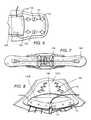
- FIG. 2is a front plan view of the quick draw brace of FIG. 1 .
- FIG. 3is a rear plan view of the quick draw brace of FIG. 1 , with fitting belts attached to the rear side of the lateral support.
- FIG. 4is an exploded view of the quick draw brace of FIG. 3 .
- FIG. 5is a plan, rear view of the quick draw brace of FIG. 1 , with fitting belts attached to the front side of the lateral support.
- FIG. 6is an exploded view of the quick draw brace of FIG. 5 .
- FIG. 7is a plan view of the quick draw brace of FIG. 6 , with the fitting belt folded over.
- FIG. 8is a perspective view of the brace of FIG. 1 with the lumbar support in a bent position.
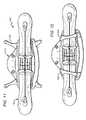
- FIG. 9is a rear plan view of an embodiment of an extender.
- FIG. 10is a front plan view of an embodiment of the extender of FIG. 9 .
- FIG. 11is a rear plan view of the quick draw brace of FIG. 7 juxtaposed with the extender of FIG. 9 .
- FIG. 12is a rear plan view of the quick draw brace of FIG. 7 with the extender of FIG. 9 attached to the quick draw brace.
- FIG. 13is a rear plan view of a reinforcement panel.
- FIG. 14is a front plan view of the reinforcement panel of FIG. 13 .
- FIG. 15is a rear plan view of the extender of FIG. 9 juxtaposed with the reinforcement panel of FIG. 13 .
- FIG. 16is a rear plan view of the extender and reinforcement panel of FIG. 15 juxtaposed with the quick draw brace of FIG. 7 .
- FIG. 17is a rear plan view of the extender, reinforcement panel, and quick draw brace of FIG. 16 coupled with one another.
- FIG. 18is an enlarged, exploded view, showing the cord guide parts within the upper left and right sections of the brace of FIG. 1 .
- FIG. 19is a perspective view of the upper left and right sections of FIG. 18 in the assembled configuration.
- FIGS. 1 and 2show a quick draw brace 100 with a lumbar support 110 , lateral supports 120 and 130 , cords 140 and 150 , and limiter 160 .
- Lumbar support 110is split into upper left section 111 , lower left section 112 , upper right section 114 , and lower right section 115 .
- Upper left section 111 and lower left section 112are configured to pivot with respect to one another along flexible joint 113
- upper right section 114 and lower right section 115are configured to pivot with respect to one another along, flexible joint 116 .
- Upper left section 111 , lower left section 112 , upper right section 114 , and lower right section 115are all preferably rigid or semi-rigid in order to provide support to the upper lumbar curve and the lower lumbar curve of the wearer.
- Lateral supports 120 and 130are preferably made of a semi-rigid or rigid material to provide lateral support to a user. While the current embodiment shows lateral support 120 being wholly contiguous with left lumbar support sections 111 and 112 , the lateral support could be made separately from the lumbar supports without departing from the scope of the current invention. It is preferred that the lateral support is a semi-rigid material that is greater than 4 or 5 inches so that the lateral support would pass the midline of the wearer.
- flexible joints 113 and 116are created by creating a thin peninsula of a substantially rigid plastic polymer separate from the lateral supports 120 and 130 . Since the peninsula is so thin (approximately 1.5 centimeters across), the upper and lower sections are able to bend along the joint, whereas they would not be able to if the peninsula was much wider. As shown in FIG. 8 , as the upper and lower sections bend inward, the lateral section does not also bow inward because of the shape of the peninsula. In reality, lateral section 130 bows outward slightly, which is largely contained when cord 150 is pulled against lateral section 130 .
- Other flexible jointscould be used, for example by using a cloth lumbar support or by adding a hinge or series of hinges to a more rigid peninsula.
- Cords 140 and 150are attached to pulleys (shown in FIGS. 18 and 19 ) in the upper and lower sections in a similar manner to the pulleys described in US2009/0192425 and U.S. Pat. No. 7,001,348.
- the lateral supports 120 and 130are coupled to the lumbar support 110 via thin, semi-rigid peninsulas, the lateral supports do not bend when the cords are pulled.
- the pulley systemcomprises an elastic band or spring that will automatically retract the cord when a force ceases to be applied to the cord.
- Limiter 160is an underlying cloth that lumbar support 110 is attached to. Since limiter 160 is made of a substantially inelastic material, limiter 160 prevents cords 140 and 150 from being pulled too far towards the holes, effectively controlling the minimum distance that the cords can be retracted. As used herein, a 5 inches (12.7 cm) of a “substantially inelastic material” does not stretch more than 3 mm without tearing. Limiter 160 also has hole 162 , which allows access to the lumbar region of the wearer for emergencies, and also prevents direct force from being applied to the lumbar region in case of severe injury.
- loophole 136is shown as a hole in lateral support 130 , but could be a recess (or an open hole) without departing from the scope of the invention. Since right adjustment mechanism 320 could attach to either a front side 131 A or a rear side 131 B of the lateral support 130 (shown best in FIG. 8 ), the length of right adjustment mechanism 320 could be altered considerably. Additionally, shorter or longer adjustment mechanisms could be provided to allow an even greater variability in sizes. The holes 132 could also be used to attach other lateral supports to accommodate larger wearers and extend the length even further.
- FIGS. 15 and 16show the front and back portions of detachable small back panel 1600 .
- Small back panel 1600is preferably made from a rigid material covered in padding to protect the regions close to the spine. As shown in FIGS. 13-17 , the small back panel could be wrapped around lumbar support 110 to prevent lumbar support 110 from bending into the lumbar curve of the wearer and to add a more rigid support structure to the lumbar region.
- the under cutsare preferably smooth so that cord 150 can be engaged therearound and smoothly moved around the lobes.
- the upper left section 111 and upper right section 114be made of a low friction polymer, such as nylon or Teflon.
- the upper right section 114is similar to upper left section 111 , and also has three cord guide lobes 50 , 52 , and 54 on its base 37 , which act as pulleys for cord 150 .
- the cord 150has an eye thereon engaged over post 49 on cord guide 114 .
- the cord 150engages around love 40 , lobe 52 , and thence lobe 44 to extend out over the base 37 .
- the cord 150is preferably a strong cord with low friction characteristics with respect to the cord guide lobes, such as nylon.
- caps 56 and 58could be used to cover the bases 38 and 37 , respectively.
- the capshave half round recesses 60 that engage over the lobes.
- the recess 60engages over lobe 44 to hold the cord in the undercut below the top of lobe 44 , and hold the cord loop on the post 49 .
- the capscan be attached in any other suitable way, for example by using adhesives or mating buttons.
- Other pulley mechanismsare contemplated, for example pulleys mounted on wheels.
- compositions and methods of providing a back bracehave been disclosed. It should be apparent, however, to those skilled in the art that many more modifications besides those already described are possible without departing from the inventive concepts herein. The inventive subject matter, therefore, is not to be restricted except in the spirit of the disclosure. Moreover, in interpreting the disclosure all terms should be interpreted in the broadest possible manner consistent with the context. In particular the terms “comprises” and “comprising” should be interpreted as referring to the elements, components, or steps in a non-exclusive manner, indicating that the referenced elements, components, or steps can be present, or utilized, or combined with other elements, components, or steps that are not expressly referenced.
Landscapes
- Health & Medical Sciences (AREA)
- Nursing (AREA)
- Orthopedic Medicine & Surgery (AREA)
- Engineering & Computer Science (AREA)
- Biomedical Technology (AREA)
- Heart & Thoracic Surgery (AREA)
- Vascular Medicine (AREA)
- Life Sciences & Earth Sciences (AREA)
- Animal Behavior & Ethology (AREA)
- General Health & Medical Sciences (AREA)
- Public Health (AREA)
- Veterinary Medicine (AREA)
- Orthopedics, Nursing, And Contraception (AREA)
- Chair Legs, Seat Parts, And Backrests (AREA)
Abstract
Description
Claims (15)
Priority Applications (3)
| Application Number | Priority Date | Filing Date | Title |
|---|---|---|---|
| US13/036,340US8372023B2 (en) | 2010-02-26 | 2011-02-28 | Highly adjustable lumbar brace |
| US13/763,964US9066792B2 (en) | 2010-02-26 | 2013-02-11 | Highly adjustable lumbar brace |
| US14/751,951US10117770B2 (en) | 2010-02-26 | 2015-06-26 | Highly adjustable lumbar brace |
Applications Claiming Priority (2)
| Application Number | Priority Date | Filing Date | Title |
|---|---|---|---|
| US30872810P | 2010-02-26 | 2010-02-26 | |
| US13/036,340US8372023B2 (en) | 2010-02-26 | 2011-02-28 | Highly adjustable lumbar brace |
Related Child Applications (1)
| Application Number | Title | Priority Date | Filing Date |
|---|---|---|---|
| US13/763,964DivisionUS9066792B2 (en) | 2010-02-26 | 2013-02-11 | Highly adjustable lumbar brace |
Publications (2)
| Publication Number | Publication Date |
|---|---|
| US20110213284A1 US20110213284A1 (en) | 2011-09-01 |
| US8372023B2true US8372023B2 (en) | 2013-02-12 |
Family
ID=43971440
Family Applications (3)
| Application Number | Title | Priority Date | Filing Date |
|---|---|---|---|
| US13/036,340ActiveUS8372023B2 (en) | 2010-02-26 | 2011-02-28 | Highly adjustable lumbar brace |
| US13/763,964ActiveUS9066792B2 (en) | 2010-02-26 | 2013-02-11 | Highly adjustable lumbar brace |
| US14/751,951Active2033-02-18US10117770B2 (en) | 2010-02-26 | 2015-06-26 | Highly adjustable lumbar brace |
Family Applications After (2)
| Application Number | Title | Priority Date | Filing Date |
|---|---|---|---|
| US13/763,964ActiveUS9066792B2 (en) | 2010-02-26 | 2013-02-11 | Highly adjustable lumbar brace |
| US14/751,951Active2033-02-18US10117770B2 (en) | 2010-02-26 | 2015-06-26 | Highly adjustable lumbar brace |
Country Status (7)
| Country | Link |
|---|---|
| US (3) | US8372023B2 (en) |
| EP (1) | EP2538898B1 (en) |
| CN (1) | CN103025278B (en) |
| BR (1) | BR112012021211A2 (en) |
| CA (1) | CA2790831A1 (en) |
| TW (1) | TWI461187B (en) |
| WO (1) | WO2011106764A1 (en) |
Cited By (35)
| Publication number | Priority date | Publication date | Assignee | Title |
|---|---|---|---|---|
| US20130158457A1 (en)* | 2010-02-26 | 2013-06-20 | Geoffrey Garth | Highly Adjustable Lumbar Brace |
| USD709614S1 (en)* | 2013-02-07 | 2014-07-22 | Orthomerica Products, Inc. | Orthotic brace |
| US8926537B2 (en) | 2009-02-26 | 2015-01-06 | Ossur Hf | Orthopedic device for treatment of the back |
| USD725786S1 (en)* | 2013-09-25 | 2015-03-31 | Aspen Medical Partners, Llc | Lower spine brace |
| WO2015094909A1 (en)* | 2013-12-17 | 2015-06-25 | 3M Innovative Properties Company | Hip pad with offset angle |
| US9220625B2 (en) | 2009-11-04 | 2015-12-29 | Ossur Hf | Thoracic lumbar sacral orthosis |
| US9314363B2 (en) | 2013-01-24 | 2016-04-19 | Ossur Hf | Orthopedic device for treating complications of the hip |
| US9370440B2 (en) | 2012-01-13 | 2016-06-21 | Ossur Hf | Spinal orthosis |
| US20160206467A1 (en)* | 2015-01-16 | 2016-07-21 | Corflex, Inc. | Lumbar Brace |
| US9439800B2 (en) | 2009-01-14 | 2016-09-13 | Ossur Hf | Orthopedic device, use of orthopedic device and method for producing same |
| US9468554B2 (en) | 2013-01-24 | 2016-10-18 | Ossur Iceland Ehf | Orthopedic device for treating complications of the hip |
| US20160310310A1 (en)* | 2015-04-24 | 2016-10-27 | Pelvicbinder, Inc. | Compression belts for selective chest compression following thoracic and cardiothoracic surgery and for selective abdominal compression following abdominal surgery |
| US9549535B1 (en)* | 2014-03-18 | 2017-01-24 | Cory Rice | Dog retention device |
| US9554935B2 (en) | 2013-01-24 | 2017-01-31 | Ossur Hf | Orthopedic device for treating complications of the hip |
| US9572705B2 (en) | 2012-01-13 | 2017-02-21 | Ossur Hf | Spinal orthosis |
| USD799707S1 (en)* | 2015-08-05 | 2017-10-10 | Aspen Medical Partners, Llc | Tightening system |
| US9795500B2 (en) | 2013-01-24 | 2017-10-24 | Ossur Hf | Orthopedic device for treating complications of the hip |
| US9872794B2 (en) | 2012-09-19 | 2018-01-23 | Ossur Hf | Panel attachment and circumference adjustment systems for an orthopedic device |
| USD816234S1 (en) | 2016-10-31 | 2018-04-24 | GB Orthopedic Bracing LLC | Lumbar brace with cold pack |
| KR20180085685A (en)* | 2017-01-19 | 2018-07-27 | 도요타지도샤가부시키가이샤 | Walking assistant harness |
| US10123514B1 (en) | 2014-03-18 | 2018-11-13 | Rice Cory S | Pet retention device |
| US10159592B2 (en) | 2015-02-27 | 2018-12-25 | Ossur Iceland Ehf | Spinal orthosis, kit and method for using the same |
| US10238524B2 (en) | 2015-06-19 | 2019-03-26 | Aspen Medical Partners, Llc | Tightening system for orthotics |
| US10420412B1 (en)* | 2019-02-26 | 2019-09-24 | Pressio LLC | Modular hip belt with gross and fine adjustment |
| US10561520B2 (en) | 2015-02-27 | 2020-02-18 | Ossur Iceland Ehf | Spinal orthosis, kit and method for using the same |
| USD893733S1 (en)* | 2017-06-07 | 2020-08-18 | Ortho Systems | Back brace |
| US10973672B2 (en)* | 2015-04-24 | 2021-04-13 | Pelvicbinder, Inc. | Compression belts for selective chest compression following thoracic and cardiothoracic surgery and for rib fracture stabilization |
| US11000439B2 (en) | 2017-09-28 | 2021-05-11 | Ossur Iceland Ehf | Body interface |
| US11213083B2 (en)* | 2018-01-29 | 2022-01-04 | Angela Marie Patton | Corset |
| US11246734B2 (en) | 2017-09-07 | 2022-02-15 | Ossur Iceland Ehf | Thoracic lumbar sacral orthosis attachment |
| US11324622B1 (en)* | 2019-08-08 | 2022-05-10 | Preferred Prescription, Inc. | Back brace belt and apparatus, and method of belt length adjustment therefor |
| USD957654S1 (en) | 2020-09-23 | 2022-07-12 | Bogdana Savchuk | Lower back support brace |
| USD989969S1 (en) | 2021-05-05 | 2023-06-20 | G Force Braces, Llc | Back brace |
| USD993426S1 (en) | 2021-05-05 | 2023-07-25 | G Force Braces, Llc | Back brace |
| US11771580B2 (en) | 2020-11-25 | 2023-10-03 | Deroyal Industries, Inc. | TLSO/LSO spine brace |
Families Citing this family (30)
| Publication number | Priority date | Publication date | Assignee | Title |
|---|---|---|---|---|
| US8303527B2 (en) | 2007-06-20 | 2012-11-06 | Exos Corporation | Orthopedic system for immobilizing and supporting body parts |
| CN102421394B (en) | 2009-02-24 | 2015-04-01 | 伊克索斯有限责任公司 | Composites for Custom Fit Products |
| US8795214B1 (en)* | 2010-07-19 | 2014-08-05 | Tony Conti | Orthotic brace and method of using |
| US8864695B2 (en)* | 2011-04-04 | 2014-10-21 | Todd M. Thornton | Adjustable brace apparatus |
| US8920353B2 (en) | 2011-05-16 | 2014-12-30 | Orthotic Solutions, Llc | Adjustable lumbo-sacral orthosis |
| USD666301S1 (en)* | 2011-12-08 | 2012-08-28 | Exos Corporation | Back brace |
| US20130178774A1 (en)* | 2011-12-26 | 2013-07-11 | Victor HAYES | Multi-strap lumbar support device |
| US20130172798A1 (en)* | 2011-12-29 | 2013-07-04 | Bio Cybernetics International, Inc. | Orthotic device having releasably attached panel extensions and method for using the same |
| US9295748B2 (en) | 2012-07-31 | 2016-03-29 | Exos Llc | Foam core sandwich splint |
| US9408738B2 (en) | 2012-08-01 | 2016-08-09 | Exos Llc | Orthopedic brace for animals |
| US9345279B2 (en)* | 2012-11-07 | 2016-05-24 | Huntex Corporation | Linked waist support for waist belt |
| US9655761B2 (en)* | 2012-11-12 | 2017-05-23 | Djo, Llc | Orthopedic back brace |
| US20170189219A1 (en)* | 2012-12-06 | 2017-07-06 | Wade K. Jensen | Lordosis Adjustable Back Brace Device |
| US9339406B2 (en)* | 2013-02-08 | 2016-05-17 | Aspen Medical Partners, Llc | Lower spine brace |
| US9095418B2 (en) | 2013-03-15 | 2015-08-04 | Breg, Inc. | Anti-twist mechanism for a mechanical advantage tensioning device on an orthosis |
| CA2941468C (en)* | 2014-03-07 | 2017-08-29 | Aspen Medical Partners, Llc | Brace having elastic and inelastic portions |
| RU2675741C2 (en) | 2014-07-11 | 2018-12-24 | Ортосервис Аг | Improved ridge corset |
| AU2016278150B2 (en)* | 2015-06-19 | 2020-04-23 | Fiji Manufacturing, Llc | Braces having inelastic and elastic materials |
| TWI601521B (en)* | 2015-11-13 | 2017-10-11 | Plus Meditech Co Ltd | Adjustable waist guard |
| DE202016100799U1 (en)* | 2016-02-16 | 2016-02-24 | Bauerfeind Ag | Deflection element for deflecting cables in or on orthopedic or medical aids or sports aids |
| WO2017147535A1 (en)* | 2016-02-25 | 2017-08-31 | Aspen Medical Partners, Llc | Recessed fasteners |
| WO2017156765A1 (en)* | 2016-03-18 | 2017-09-21 | 王祐谦 | Orthotic device and thread guide structure thereof |
| USD812236S1 (en) | 2016-06-17 | 2018-03-06 | Aspen Medical Partners, Llc | Back brace |
| US11540935B2 (en)* | 2017-06-07 | 2023-01-03 | Ortho Systems | Welded back brace |
| US20190192330A1 (en)* | 2017-12-21 | 2019-06-27 | Trevor J. Theriot | Single Pull Lumbar Support Brace |
| FR3089407B1 (en)* | 2018-12-05 | 2020-12-18 | Thuasne | Orthopedic belt with gripping elements |
| US12138192B1 (en) | 2021-03-05 | 2024-11-12 | Aspen Medical Products, Llc | Back brace with padded sleeve |
| US12220339B2 (en) | 2021-03-05 | 2025-02-11 | Aspen Medical Products, Llc | Back brace with height adjustable rigid panel |
| WO2023150175A1 (en)* | 2022-02-01 | 2023-08-10 | Aspen Medical Products, Llc | Orthopedic brace having telescopic lateral panels and an adjusting pulley system |
| CN218999629U (en)* | 2022-11-21 | 2023-05-12 | 东莞市福顺体育运动用品有限公司 | Novel waistband of elasticity is adjusted to knob |
Citations (24)
| Publication number | Priority date | Publication date | Assignee | Title |
|---|---|---|---|---|
| US2036484A (en)* | 1932-12-14 | 1936-04-07 | S H Camp & Company | Surgical support |
| US2100964A (en)* | 1936-02-04 | 1937-11-30 | James R Kendrick Co Inc | Surgical belt |
| US2117309A (en)* | 1936-10-20 | 1938-05-17 | Lewis A Fritsch | Belt support |
| US4080962A (en)* | 1975-07-24 | 1978-03-28 | Joseph Berkeley | Posture-training brace |
| FR2682869A1 (en)* | 1991-10-29 | 1993-04-30 | Francaise Coop Pharma | Vertebral immobilisation corset |
| US5346461A (en) | 1992-10-23 | 1994-09-13 | Bio-Cybernetics International | Electromechanical back brace apparatus |
| US5433697A (en)* | 1993-12-20 | 1995-07-18 | Cox; Michael F. | Conformable back brace with abdominal support |
| US6102879A (en) | 1999-01-04 | 2000-08-15 | Innovative Orthotics And Rehabilitation, Inc. | Adjustable back brace with posterior wound clearance |
| US6190343B1 (en) | 1999-12-10 | 2001-02-20 | Bio Cybernetics International | Cruciform anterior spinal hyperextension orthosis |
| US6213968B1 (en) | 1998-06-18 | 2001-04-10 | Biocybernetics International | Custom fitted orthotic device |
| US20010034498A1 (en) | 2000-02-07 | 2001-10-25 | Heyman Arnold M. | Orthotic device and methods for limiting expansion of a patient's chest |
| US6503215B1 (en) | 1998-12-03 | 2003-01-07 | Holger C.W. Reinhardt | Bandage for parts of the body |
| US6602214B2 (en) | 1999-10-19 | 2003-08-05 | Bio Cybernetics International | Orthotic trauma device |
| US6676620B2 (en)* | 2000-12-05 | 2004-01-13 | Orthomerica Products, Inc. | Modular orthosis closure system and method |
| US20050251074A1 (en) | 2004-05-07 | 2005-11-10 | Latham Mark A | String arrangement of a separate back immobilizing, dynamically self-adjusting, customizing back support for a vertebra related patient |
| US6964644B1 (en)* | 1999-06-01 | 2005-11-15 | Garth Geoffrey C | Back brace |
| US20050267390A1 (en)* | 2003-05-19 | 2005-12-01 | Geoffrey Garth | Double pull body brace |
| US20050273025A1 (en) | 2004-05-19 | 2005-12-08 | Houser Guy M | Braces having an assembly for exerting a manually adjustable force on a limb of a user |
| US20060004313A1 (en) | 2004-06-22 | 2006-01-05 | Heinz Thomas J | Cured body shell and method of making the same |
| US7118543B2 (en)* | 2003-09-09 | 2006-10-10 | Top Shelf Manufacturing, Llc | Orthosis closure system with mechanical advantage |
| US20090082707A1 (en) | 2007-07-27 | 2009-03-26 | Royce Rumsey | Orthotic Device |
| US20090192425A1 (en)* | 2003-05-19 | 2009-07-30 | Garth Geoffrey C | Highly Adjustable Lumbar Support And Methods |
| US20090204042A1 (en)* | 2008-02-07 | 2009-08-13 | Dae Shik Park | Back brace frame with two individual power modules |
| US20100217167A1 (en)* | 2009-02-26 | 2010-08-26 | Arni Thor Ingimundarson | Orthopedic device for treatment of the back |
Family Cites Families (8)
| Publication number | Priority date | Publication date | Assignee | Title |
|---|---|---|---|---|
| US4640269A (en) | 1984-07-30 | 1987-02-03 | Joan Goins | Back brace having strap with widened middle portion for pad |
| US5690609A (en)* | 1996-05-13 | 1997-11-25 | Heinze, Iii; Frank D. | Compound abdominal and back support belt system |
| US6478759B1 (en)* | 2000-03-09 | 2002-11-12 | Deroyal Industries, Inc. | Thoraco-lumbo-sacral orthosis |
| US6322529B1 (en)* | 2000-10-24 | 2001-11-27 | Joon Young Chung | Detachment type waist protecting belt |
| US6702770B2 (en)* | 2002-03-21 | 2004-03-09 | The Bremer Group Company | Posterior lumbar lordosis orthotic device |
| US20070017945A1 (en) | 2005-07-25 | 2007-01-25 | Willis John A | Lifting and carrying aid |
| CN201211255Y (en)* | 2008-07-09 | 2009-03-25 | 贾广田 | Semi-elastic type waist protecting girdle |
| TWI461187B (en)* | 2010-02-26 | 2014-11-21 | Aspen Medical Partners Llc | Highly adjustable lumbar brace |
- 2011
- 2011-02-25TWTW100106495Apatent/TWI461187B/enactive
- 2011-02-28USUS13/036,340patent/US8372023B2/enactiveActive
- 2011-02-28EPEP11707052.4Apatent/EP2538898B1/enactiveActive
- 2011-02-28WOPCT/US2011/026435patent/WO2011106764A1/enactiveApplication Filing
- 2011-02-28CACA2790831Apatent/CA2790831A1/ennot_activeAbandoned
- 2011-02-28CNCN201180020721.3Apatent/CN103025278B/enactiveActive
- 2011-02-28BRBR112012021211Apatent/BR112012021211A2/ennot_activeIP Right Cessation
- 2013
- 2013-02-11USUS13/763,964patent/US9066792B2/enactiveActive
- 2015
- 2015-06-26USUS14/751,951patent/US10117770B2/enactiveActive
Patent Citations (30)
| Publication number | Priority date | Publication date | Assignee | Title |
|---|---|---|---|---|
| US2036484A (en)* | 1932-12-14 | 1936-04-07 | S H Camp & Company | Surgical support |
| US2100964A (en)* | 1936-02-04 | 1937-11-30 | James R Kendrick Co Inc | Surgical belt |
| US2117309A (en)* | 1936-10-20 | 1938-05-17 | Lewis A Fritsch | Belt support |
| US4080962A (en)* | 1975-07-24 | 1978-03-28 | Joseph Berkeley | Posture-training brace |
| FR2682869A1 (en)* | 1991-10-29 | 1993-04-30 | Francaise Coop Pharma | Vertebral immobilisation corset |
| US5346461A (en) | 1992-10-23 | 1994-09-13 | Bio-Cybernetics International | Electromechanical back brace apparatus |
| US5437617A (en) | 1992-10-23 | 1995-08-01 | Bio Cybernetics International | Electromechanical back brace apparatus |
| USRE35940E (en) | 1992-10-23 | 1998-10-27 | Bio-Cybernetics, International | Electromechanical back brace apparatus |
| US5433697A (en)* | 1993-12-20 | 1995-07-18 | Cox; Michael F. | Conformable back brace with abdominal support |
| US6213968B1 (en) | 1998-06-18 | 2001-04-10 | Biocybernetics International | Custom fitted orthotic device |
| US20010020144A1 (en) | 1998-06-18 | 2001-09-06 | Bio Cybernetics International | Custom fitted orthotic device |
| US6503215B1 (en) | 1998-12-03 | 2003-01-07 | Holger C.W. Reinhardt | Bandage for parts of the body |
| US6102879A (en) | 1999-01-04 | 2000-08-15 | Innovative Orthotics And Rehabilitation, Inc. | Adjustable back brace with posterior wound clearance |
| US6964644B1 (en)* | 1999-06-01 | 2005-11-15 | Garth Geoffrey C | Back brace |
| US6602214B2 (en) | 1999-10-19 | 2003-08-05 | Bio Cybernetics International | Orthotic trauma device |
| US6190343B1 (en) | 1999-12-10 | 2001-02-20 | Bio Cybernetics International | Cruciform anterior spinal hyperextension orthosis |
| US20010034498A1 (en) | 2000-02-07 | 2001-10-25 | Heyman Arnold M. | Orthotic device and methods for limiting expansion of a patient's chest |
| US6517502B2 (en)* | 2000-02-07 | 2003-02-11 | Biocybernetics International | Orthotic device an methods for limiting expansion of a patient's chest |
| US7186229B2 (en) | 2000-12-05 | 2007-03-06 | Orthomerica Products, Inc. | Modular orthosis closure system and method |
| US6676620B2 (en)* | 2000-12-05 | 2004-01-13 | Orthomerica Products, Inc. | Modular orthosis closure system and method |
| US7201727B2 (en)* | 2000-12-05 | 2007-04-10 | Orthomerica Products, Inc. | Modular orthosis closure system and method |
| US20050267390A1 (en)* | 2003-05-19 | 2005-12-01 | Geoffrey Garth | Double pull body brace |
| US20090192425A1 (en)* | 2003-05-19 | 2009-07-30 | Garth Geoffrey C | Highly Adjustable Lumbar Support And Methods |
| US7118543B2 (en)* | 2003-09-09 | 2006-10-10 | Top Shelf Manufacturing, Llc | Orthosis closure system with mechanical advantage |
| US20050251074A1 (en) | 2004-05-07 | 2005-11-10 | Latham Mark A | String arrangement of a separate back immobilizing, dynamically self-adjusting, customizing back support for a vertebra related patient |
| US20050273025A1 (en) | 2004-05-19 | 2005-12-08 | Houser Guy M | Braces having an assembly for exerting a manually adjustable force on a limb of a user |
| US20060004313A1 (en) | 2004-06-22 | 2006-01-05 | Heinz Thomas J | Cured body shell and method of making the same |
| US20090082707A1 (en) | 2007-07-27 | 2009-03-26 | Royce Rumsey | Orthotic Device |
| US20090204042A1 (en)* | 2008-02-07 | 2009-08-13 | Dae Shik Park | Back brace frame with two individual power modules |
| US20100217167A1 (en)* | 2009-02-26 | 2010-08-26 | Arni Thor Ingimundarson | Orthopedic device for treatment of the back |
Cited By (63)
| Publication number | Priority date | Publication date | Assignee | Title |
|---|---|---|---|---|
| US9439800B2 (en) | 2009-01-14 | 2016-09-13 | Ossur Hf | Orthopedic device, use of orthopedic device and method for producing same |
| US12127965B2 (en) | 2009-02-26 | 2024-10-29 | Ossur Hf | Orthopedic device for treatment of the back |
| US8926537B2 (en) | 2009-02-26 | 2015-01-06 | Ossur Hf | Orthopedic device for treatment of the back |
| US8945034B2 (en) | 2009-02-26 | 2015-02-03 | Ossur Hf | Orthopedic device for treatment of the back |
| US9414953B2 (en) | 2009-02-26 | 2016-08-16 | Ossur Hf | Orthopedic device for treatment of the back |
| US10828186B2 (en) | 2009-02-26 | 2020-11-10 | Ossur Hf | Orthopedic device for treatment of the back |
| US9220625B2 (en) | 2009-11-04 | 2015-12-29 | Ossur Hf | Thoracic lumbar sacral orthosis |
| US9597219B2 (en) | 2009-11-04 | 2017-03-21 | Ossur Hf | Thoracic lumbar sacral orthosis |
| US10617552B2 (en) | 2009-11-04 | 2020-04-14 | Ossur Hf | Thoracic lumbar sacral orthosis |
| US20130158457A1 (en)* | 2010-02-26 | 2013-06-20 | Geoffrey Garth | Highly Adjustable Lumbar Brace |
| US10117770B2 (en)* | 2010-02-26 | 2018-11-06 | Aspen Medical Partners, Llc | Highly adjustable lumbar brace |
| US9066792B2 (en)* | 2010-02-26 | 2015-06-30 | Aspen Medical Partners, Llc | Highly adjustable lumbar brace |
| US20150290019A1 (en)* | 2010-02-26 | 2015-10-15 | Aspen Medical Partners, Llc | Highly Adjustable Lumbar Brace |
| US12186226B2 (en) | 2012-01-13 | 2025-01-07 | Ossur Hf | Spinal orthosis |
| US9572705B2 (en) | 2012-01-13 | 2017-02-21 | Ossur Hf | Spinal orthosis |
| US10898365B2 (en) | 2012-01-13 | 2021-01-26 | Ossur Hf | Spinal orthosis |
| US9370440B2 (en) | 2012-01-13 | 2016-06-21 | Ossur Hf | Spinal orthosis |
| US11484428B2 (en) | 2012-09-19 | 2022-11-01 | Ossur Hf | Panel attachment and circumference adjustment systems for an orthopedic device |
| US9872794B2 (en) | 2012-09-19 | 2018-01-23 | Ossur Hf | Panel attachment and circumference adjustment systems for an orthopedic device |
| US10980657B2 (en) | 2012-09-19 | 2021-04-20 | Ossur Hf | Panel attachment and circumference adjustment systems for an orthopedic device |
| US11259948B2 (en) | 2013-01-24 | 2022-03-01 | Ossur Hf | Orthopedic device for treating complications of the hip |
| US9314363B2 (en) | 2013-01-24 | 2016-04-19 | Ossur Hf | Orthopedic device for treating complications of the hip |
| US9795500B2 (en) | 2013-01-24 | 2017-10-24 | Ossur Hf | Orthopedic device for treating complications of the hip |
| US9393144B2 (en) | 2013-01-24 | 2016-07-19 | Ossur Hf | Orthopedic device for treating complications of the hip |
| US12433778B2 (en) | 2013-01-24 | 2025-10-07 | Ossur Hf | Orthopedic device for treating complications of the hip |
| US9987158B2 (en) | 2013-01-24 | 2018-06-05 | Ossur Hf | Orthopedic device for treating complications of the hip |
| US9554935B2 (en) | 2013-01-24 | 2017-01-31 | Ossur Hf | Orthopedic device for treating complications of the hip |
| US10357391B2 (en) | 2013-01-24 | 2019-07-23 | Ossur Hf | Orthopedic device for treating complications of the hip |
| US9468554B2 (en) | 2013-01-24 | 2016-10-18 | Ossur Iceland Ehf | Orthopedic device for treating complications of the hip |
| USD709614S1 (en)* | 2013-02-07 | 2014-07-22 | Orthomerica Products, Inc. | Orthotic brace |
| USD725786S1 (en)* | 2013-09-25 | 2015-03-31 | Aspen Medical Partners, Llc | Lower spine brace |
| WO2015094909A1 (en)* | 2013-12-17 | 2015-06-25 | 3M Innovative Properties Company | Hip pad with offset angle |
| US10123514B1 (en) | 2014-03-18 | 2018-11-13 | Rice Cory S | Pet retention device |
| US9549535B1 (en)* | 2014-03-18 | 2017-01-24 | Cory Rice | Dog retention device |
| US10143583B2 (en)* | 2015-01-16 | 2018-12-04 | Corflex, Inc. | Lumbar brace |
| US20160206467A1 (en)* | 2015-01-16 | 2016-07-21 | Corflex, Inc. | Lumbar Brace |
| US11273064B2 (en) | 2015-02-27 | 2022-03-15 | Ossur Iceland Ehf | Spinal orthosis, kit and method for using the same |
| US11571323B2 (en) | 2015-02-27 | 2023-02-07 | Ossur Iceland Ehf | Spinal orthosis, kit and method for using the same |
| US10159592B2 (en) | 2015-02-27 | 2018-12-25 | Ossur Iceland Ehf | Spinal orthosis, kit and method for using the same |
| US10561520B2 (en) | 2015-02-27 | 2020-02-18 | Ossur Iceland Ehf | Spinal orthosis, kit and method for using the same |
| US20160310310A1 (en)* | 2015-04-24 | 2016-10-27 | Pelvicbinder, Inc. | Compression belts for selective chest compression following thoracic and cardiothoracic surgery and for selective abdominal compression following abdominal surgery |
| US10973672B2 (en)* | 2015-04-24 | 2021-04-13 | Pelvicbinder, Inc. | Compression belts for selective chest compression following thoracic and cardiothoracic surgery and for rib fracture stabilization |
| US10092440B2 (en)* | 2015-04-24 | 2018-10-09 | Pelvicbinder, Inc. | Compression belts for selective chest compression following thoracic and cardiothoracic surgery and for selective abdominal compression following abdominal surgery |
| US10238524B2 (en) | 2015-06-19 | 2019-03-26 | Aspen Medical Partners, Llc | Tightening system for orthotics |
| USD799707S1 (en)* | 2015-08-05 | 2017-10-10 | Aspen Medical Partners, Llc | Tightening system |
| USD816234S1 (en) | 2016-10-31 | 2018-04-24 | GB Orthopedic Bracing LLC | Lumbar brace with cold pack |
| US10881576B2 (en) | 2017-01-19 | 2021-01-05 | Toyota Jidosha Kabushiki Kaisha | Walking assistant harness |
| KR20180085685A (en)* | 2017-01-19 | 2018-07-27 | 도요타지도샤가부시키가이샤 | Walking assistant harness |
| USD893733S1 (en)* | 2017-06-07 | 2020-08-18 | Ortho Systems | Back brace |
| US11246734B2 (en) | 2017-09-07 | 2022-02-15 | Ossur Iceland Ehf | Thoracic lumbar sacral orthosis attachment |
| US11684506B2 (en) | 2017-09-07 | 2023-06-27 | Ossur Iceland Ehf | Thoracic lumbar sacral orthosis attachment |
| US12090079B2 (en) | 2017-09-07 | 2024-09-17 | Ossur Iceland Ehf | Thoracic lumbar sacral orthosis attachment |
| US11000439B2 (en) | 2017-09-28 | 2021-05-11 | Ossur Iceland Ehf | Body interface |
| US11850206B2 (en) | 2017-09-28 | 2023-12-26 | Ossur Iceland Ehf | Body interface |
| US11213083B2 (en)* | 2018-01-29 | 2022-01-04 | Angela Marie Patton | Corset |
| US10638827B1 (en)* | 2019-02-26 | 2020-05-05 | Pressio LLC | Modular hip belt with gross and fine adjustment |
| US10420412B1 (en)* | 2019-02-26 | 2019-09-24 | Pressio LLC | Modular hip belt with gross and fine adjustment |
| US11324622B1 (en)* | 2019-08-08 | 2022-05-10 | Preferred Prescription, Inc. | Back brace belt and apparatus, and method of belt length adjustment therefor |
| US12357490B2 (en) | 2019-08-08 | 2025-07-15 | Preferred Prescription, Inc. | Back brace with enhanced height support and adjustment capability |
| USD957654S1 (en) | 2020-09-23 | 2022-07-12 | Bogdana Savchuk | Lower back support brace |
| US11771580B2 (en) | 2020-11-25 | 2023-10-03 | Deroyal Industries, Inc. | TLSO/LSO spine brace |
| USD993426S1 (en) | 2021-05-05 | 2023-07-25 | G Force Braces, Llc | Back brace |
| USD989969S1 (en) | 2021-05-05 | 2023-06-20 | G Force Braces, Llc | Back brace |
Also Published As
| Publication number | Publication date |
|---|---|
| CN103025278B (en) | 2016-03-02 |
| US20130158457A1 (en) | 2013-06-20 |
| CA2790831A1 (en) | 2011-09-01 |
| US20110213284A1 (en) | 2011-09-01 |
| WO2011106764A1 (en) | 2011-09-01 |
| CN103025278A (en) | 2013-04-03 |
| TW201138745A (en) | 2011-11-16 |
| US9066792B2 (en) | 2015-06-30 |
| EP2538898B1 (en) | 2016-08-10 |
| US20150290019A1 (en) | 2015-10-15 |
| TWI461187B (en) | 2014-11-21 |
| BR112012021211A2 (en) | 2019-09-03 |
| EP2538898A1 (en) | 2013-01-02 |
| US10117770B2 (en) | 2018-11-06 |
Similar Documents
| Publication | Publication Date | Title |
|---|---|---|
| US10117770B2 (en) | Highly adjustable lumbar brace | |
| US12127965B2 (en) | Orthopedic device for treatment of the back | |
| US8992451B2 (en) | Shoulder orthosis having a supportive strapping system | |
| US7244239B2 (en) | Shoulder stabilizing restraint | |
| EP2223669A1 (en) | Highly adjustable lumbar support and methods | |
| US7449006B2 (en) | Equalizing lumbar orthosis | |
| US8795214B1 (en) | Orthotic brace and method of using | |
| US20170348131A1 (en) | Orthopedic device, strap system and method for securing the same | |
| US11850175B2 (en) | Orthopedic device, strap system and method for securing the same | |
| US9504596B1 (en) | Convertible orthotic brace | |
| CN1311648A (en) | wearing well-fitting orthotics | |
| JP6296811B2 (en) | Waist supporter | |
| EP3731788B1 (en) | Orthopedic device, strap system and method for securing the same | |
| JP2662192B2 (en) | Cervical orthosis | |
| JP2025504137A (en) | Orthopedic devices and how to wear them | |
| HK1144769A (en) | Highly adjustable lumbar support and methods |
Legal Events
| Date | Code | Title | Description |
|---|---|---|---|
| STCF | Information on status: patent grant | Free format text:PATENTED CASE | |
| AS | Assignment | Owner name:ASPEN MEDICAL PARTNERS, LLC, CALIFORNIA Free format text:ASSIGNMENT OF ASSIGNORS INTEREST;ASSIGNORS:GARTH, GEOFFREY;BURKE, STEVEN;ROMO, ALBERT;AND OTHERS;SIGNING DATES FROM 20130930 TO 20131007;REEL/FRAME:031385/0216 | |
| FPAY | Fee payment | Year of fee payment:4 | |
| AS | Assignment | Owner name:ANTARES CAPITAL LP, AS AGENT, ILLINOIS Free format text:SECURITY INTEREST;ASSIGNORS:ASPEN MEDICAL HOLDINGS, LLC;ASPEN MEDICAL PARTNERS, LLC;CARSAR, LLC;AND OTHERS;REEL/FRAME:049417/0331 Effective date:20190610 | |
| AS | Assignment | Owner name:FIJI MANUFACTURING, LLC, CALIFORNIA Free format text:ASSIGNMENT OF ASSIGNORS INTEREST;ASSIGNOR:ASPEN MEDICAL PARTNERS, LLC;REEL/FRAME:051982/0246 Effective date:20200227 | |
| MAFP | Maintenance fee payment | Free format text:PAYMENT OF MAINTENANCE FEE, 8TH YR, SMALL ENTITY (ORIGINAL EVENT CODE: M2552); ENTITY STATUS OF PATENT OWNER: SMALL ENTITY Year of fee payment:8 | |
| AS | Assignment | Owner name:ASPEN MEDICAL PRODUCTS, LLC, CALIFORNIA Free format text:ASSIGNMENT OF ASSIGNORS INTEREST;ASSIGNOR:FIJI MANUFACTURING, LLC;REEL/FRAME:067141/0086 Effective date:20210727 | |
| MAFP | Maintenance fee payment | Free format text:PAYMENT OF MAINTENANCE FEE, 12TH YR, SMALL ENTITY (ORIGINAL EVENT CODE: M2553); ENTITY STATUS OF PATENT OWNER: SMALL ENTITY Year of fee payment:12 |