US8371695B2 - Real-time spectrally-adjustable ophthalmic illumination - Google Patents
Real-time spectrally-adjustable ophthalmic illuminationDownload PDFInfo
- Publication number
- US8371695B2 US8371695B2US13/076,639US201113076639AUS8371695B2US 8371695 B2US8371695 B2US 8371695B2US 201113076639 AUS201113076639 AUS 201113076639AUS 8371695 B2US8371695 B2US 8371695B2
- Authority
- US
- United States
- Prior art keywords
- color
- combined light
- radiometric
- intensity
- spectral
- Prior art date
- Legal status (The legal status is an assumption and is not a legal conclusion. Google has not performed a legal analysis and makes no representation as to the accuracy of the status listed.)
- Active, expires
Links
- 238000005286illuminationMethods0.000titleclaimsdescription35
- 230000003595spectral effectEffects0.000claimsabstractdescription42
- 238000005070samplingMethods0.000claimsabstractdescription9
- 239000013307optical fiberSubstances0.000claimsabstractdescription8
- 210000001525retinaAnatomy0.000claimsdescription16
- 230000002207retinal effectEffects0.000claimsdescription10
- 238000000034methodMethods0.000claimsdescription9
- 239000003086colorantSubstances0.000claimsdescription8
- 230000004044responseEffects0.000claimsdescription4
- 238000000926separation methodMethods0.000claimsdescription4
- 238000005259measurementMethods0.000claimsdescription3
- 239000000523sampleSubstances0.000description12
- 230000004907fluxEffects0.000description11
- 239000000835fiberSubstances0.000description8
- 230000006870functionEffects0.000description8
- 230000003287optical effectEffects0.000description4
- 238000001228spectrumMethods0.000description4
- 230000000694effectsEffects0.000description3
- 238000009877renderingMethods0.000description3
- 230000001629suppressionEffects0.000description3
- 238000001356surgical procedureMethods0.000description3
- 238000002560therapeutic procedureMethods0.000description2
- 208000001351Epiretinal MembraneDiseases0.000description1
- 230000003416augmentationEffects0.000description1
- 230000006399behaviorEffects0.000description1
- 238000001514detection methodMethods0.000description1
- 239000000975dyeSubstances0.000description1
- 238000012986modificationMethods0.000description1
- 230000004048modificationEffects0.000description1
- 230000000649photocoagulationEffects0.000description1
- 102000004169proteins and genesHuman genes0.000description1
- 108090000623proteins and genesProteins0.000description1
- 238000000985reflectance spectrumMethods0.000description1
- 230000004256retinal imageEffects0.000description1
- 238000013519translationMethods0.000description1
- 238000001429visible spectrumMethods0.000description1
- 238000012800visualizationMethods0.000description1
Images


Classifications
- A—HUMAN NECESSITIES
- A61—MEDICAL OR VETERINARY SCIENCE; HYGIENE
- A61B—DIAGNOSIS; SURGERY; IDENTIFICATION
- A61B3/00—Apparatus for testing the eyes; Instruments for examining the eyes
- A61B3/0008—Apparatus for testing the eyes; Instruments for examining the eyes provided with illuminating means
Definitions
- This applicationrelates to illumination in ophthalmic procedures and more particularly to ophthalmic illumination with spectral adjustment.
- Ophthalmic illuminatorsallow a surgeon to illuminate the interior structure of the eye such as the vitreous and the retina during surgical procedures.
- an endoscopic ophthalmic illuminator(endo-illuminator) includes an optical fiber within the bore of a cannula. By driving a proximal end of the optical fiber with a suitable light source, light emitted from a distal end of the fiber illuminates the desired portion of the eye during a surgical procedure.
- a physicianmay illuminate the eye with fiber optic illumination while using an ophthalmic microscope.
- spectral outputOne factor for ophthalmic illumination is the spectral output.
- biological tissueis a broadband reflector such that white light illumination is preferable.
- white light illuminationthere are situations such as the use of dyes or the detection of certain proteins in which a physician will prefer a suitably colored illumination.
- most conventional white light sourcessuch as a white light LED provide a fixed spectral output.
- the desired spectral output for ophthalmic illuminationmay vary depending upon numerous factors that are difficult to predict a priori such as: the physical appearance of the retina; the desired illuminance (luminous flux/area) in the operating field, the desired Color Rending Index (CRI) for adequate visualization of the retinal tissue; and the degree of contrast enhancement or color suppression desired during the surgery;
- Another factor for ophthalmic illuminationis the resulting aphakic hazard potential, which is the potential for light-induced photochemical damage to the retina.
- the aphakic hazardcan thus be virtually eliminated by using only those wavelengths longer than 510 nm.
- the desired spectral output for ophthalmic illuminationmay also vary according to the expected length of the operation and the proximity of the distal end of the illumination probe to the retina.
- an ophthalmic illuminatorincludes: a plurality of color sources, each color source producing a light of a corresponding color; a combiner for combining the light from the color sources to produced a combined light; at least one optical fiber configured to receive the combined light and propagate the received combined light towards a distal end of the ophthalmic illuminator; and a controller for controlling an intensity for each of the color sources responsive to a sampling of a spectral content for the combined light.
- a method of controlling an ophthalmic illuminationincludes: producing a plurality of lights of different colors; combining the plurality of lights of different colors to produce a combined light; illuminating an operating field within a human eye with the combined light; measuring a spectral radiometric function for the combined light during the illumination; and responsive to the measurement, adjusting an intensity for at least one of the lights of different colors.
- an ophthalmic illuminatorincludes: a red LED; a green LED; a blue LED; a combiner for combining light from the LEDs to produce a combined light; at least one optical fiber configured to receive the combined light and propagate the received combined light towards a distal end of the ophthalmic illuminator; and a controller configured to control an intensity for each of LEDs responsive to a sampling of a spectral content for the combined light.
- FIG. 1illustrates a spectrally-adjustable ophthalmic fiber illumination probe.
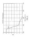
- FIG. 2is a graph of the aphakic hazard function.
- FIG. 3illustrates the spectral power distribution bands for various color LED sources.
- FIG. 4is a graph of the CIE tristimulus functions.
- FIG. 1illustrates a spectrally-adjustable ophthalmic illuminator probe 100 .
- Illuminator 100includes a red LED source 105 , a blue LED source 110 and a green LED source 115 . Each LED associates with a corresponding collimating lens.
- red light from red (R) LED source 105is collimated through a lens 120
- blue light from blue (B) LED source 110is collimated through a lens 125
- green light from green (G) LED source 115is collimated through a lens 130 .
- the resulting collimated light beamsare received at a combiner 135 to produce a combined light beam 140 .
- Combiner 135may comprise a Phillips prism, a dichroic cube, or other suitable optical combiner.
- combined light beam 140may nominally be a white light beam.
- the radiant flux (intensity) for each light sourcemay be tuned as desired.
- a variable current amplifier 145may vary the radiant flux produced by red LED source 105
- a variable current amplifier 150may vary the radiant flux from blue LED source 110
- a variable current amplifier 155may vary the radian flux for green LED source 115 .
- Other techniquesmay also be used to vary or tune the light intensity from each source.
- constant power sourcesmay drive the LEDs through pulse width modulators.
- a controller 160such as a microprocessor or microcontroller controls the radiant flux from each light source accordingly. Thus, for illuminator 100 , controller 160 controls the amount of gain applied by each current amplifier.
- controller 160automatically adjusts the gain responsive to feedback as sensed through an optical sampler 165 that samples combined beam 140 .
- optical sampler 165may comprise a beam splitter or a folding mirror to split off a relatively small portion of the combined beam 140 as a sampled beam 170 .
- controllerreceives data from a spectroradiometer 190 that receives sampled beam 170 .
- the remaining unsampled portion of combined beam 140is received by a condensing optic lens 180 so as to couple into an optic fiber 185 (or optic fiber bundle).
- Fiber 185may thus be the illumination source in ophthalmic instruments such as an ophthalmic microscope, slit lamps, indirect ophthalmoscopes, and fiber endo-illuminators.
- Controller 160is also responsive to user input such that a physician may manually command the appropriate gains so as to achieve the desired spectral content for combined beam 140 .
- the general desire for white vitreoretinal illuminationflows from the phenomenon of color rendering, which is the ability of the illuminating light to render the appearance of various colors as they should appear to the human observer.
- color rendering indexCRI
- White light illuminationthus has a high CRI value.
- the CRI indexwill drop. For example, illumination at wavelengths only of 510 nm in wavelength or longer will have a relatively low CRI.
- controller 160may automatically control the CRI by adjusting the radiant flux from each source to achieve a desired chromaticity value as defined by, for example, the International Commission on Illumination (CIE) 1931 color space.
- CIEInternational Commission on Illumination
- controller 160in response to sensing the spectral content of the combined light advantageously minimizes or eliminates aphakic hazard in certain embodiments.
- stringent guidelines on total aphakic exposuresuch as 10 J/cm 2 may be satisfied, thereby increasing patient safety.
- controller 160to properly calculate the total aphakic irradiance, a correlation between the irradiance at the retina and the radiant flux measured by spectroradiometer 190 of sampled beam 170 is useful.
- the irradiance on the retinadepends upon a number of factors such as the separation between an emitting distal end of a probe holding fiber 185 and the retina.
- a typical separation between the probe and the retina for conventional endo-illuminatorsis 5 to 15 mm. However, for a laser probe such as used in retinal photocoagulation therapy, the separation may be in the range of 2 to 4 mm.
- Another factor affecting time-averaged retinal irradianceis whether the illumination probe is pointed at the same area of the retina as opposed to sequentially moving the illumination to different portions of the retina. Other factors include the spread angle of the emitted light beam, the incident angle for the emitted light beam onto the retina, and the detailed structure and physical condition of the retina as well as obscuring effects of other tissues such as vitreous and epiretinal membranes.
- illumination probe 100may include an RFID tag 195 so that an RFID interrogator (not illustrated) may read associated RFID data from tag 195 and provide the data to controller 160 .
- an estimate of expected conditions and beam spread angle associated with a given probeis loaded onto tag 195 so that controller 160 can correlate between spectral power measurements of sampled beam 170 and a corresponding irradiance at the retina.
- Spectroradiometer 190may sample the entire visible spectrum for sampled beam 170 or merely sample the spectral power at selected wavelengths having the expected predominant optical energy. Having determined some suitable radiometric measure (denoted as R) such as radiometric flux or irradiance at the sampled wavelengths, controller 160 may thus construct a corresponding spectral radiometric function R′( ⁇ ). e.g. watts/nm.
- Rradiometric measure
- controller 160may thus construct a corresponding spectral radiometric function R′( ⁇ ). e.g. watts/nm.
- R′( ⁇ )e.g. watts/nm.
- An accurate measure of the aphakic hazardrequires a translation of such a radiometric quantity to an aphakic radiometric quantity such as aphakic irradiance or aphakic radiometric power.
- some maximum thresholdsuch as 10 J/cm 2
- contrastis typically defined as the luminance ratio between the brightest and dimmest portions of the retinal image. Whether a particular retinal tissue reflects strongly or weakly depends on its reflectance spectrum multiplied by the illumination spectrum as integrated over the visible wavelengths. If a particular retinal tissue is highly absorptive over a spectral region corresponding to one of the color sources but a different retinal tissue is highly reflective at that same wavelength, controller 160 could increase the contrast between the two retinal tissues by suppressing the remaining color sources. Alternatively, there may be high contrast in the presence of white light (full spectrum) illumination such that controller 160 tunes the color sources to effect white light illumination.
- white lightfull spectrum
- contrast enhancement or suppressionmay be desirable.
- the degree of suppression or enhancementdepends upon the spectral behavior for the various light sources and the spectral reflectance characteristics of the tissue being observed. As seen in FIG. 3 , which illustrates the spectra for various commercially-available LED color sources, these sources typically have relatively narrow spectral bandwidths. Such narrowband emission enhances the ability to increase or suppress contrast as desired by controller 160 .
- controller 160may be configured to measure the chromaticity coordinates for the current illumination.
- illuminator 100has been discussed with regard to three independent color sources, it will be appreciated that white light illumination can be achieved with just two sources. Conversely, rather than just use a RGB combination as discussed above, a greater number of color channels may used such as four, five, or more color channels may be implemented.
- the spectral content of the combined lightmay be characterized using a color camera instead of a spectroradiometer.
Landscapes
- Life Sciences & Earth Sciences (AREA)
- Health & Medical Sciences (AREA)
- Medical Informatics (AREA)
- Biophysics (AREA)
- Ophthalmology & Optometry (AREA)
- Engineering & Computer Science (AREA)
- Biomedical Technology (AREA)
- Heart & Thoracic Surgery (AREA)
- Physics & Mathematics (AREA)
- Molecular Biology (AREA)
- Surgery (AREA)
- Animal Behavior & Ethology (AREA)
- General Health & Medical Sciences (AREA)
- Public Health (AREA)
- Veterinary Medicine (AREA)
- Circuit Arrangement For Electric Light Sources In General (AREA)
Abstract
Description
Raph=∫R′(λ)A(λ)dλ
where Raphis an aphakically weighted radiometric quantity as determined by the type of radiometric quantity (radiometric flux, irradiance, etc.) used to establish R′(λ).
where R′( ) is the spectral radiometric function discussed above. Given the CIE primaries,
x=
y=
Claims (19)
Priority Applications (1)
| Application Number | Priority Date | Filing Date | Title |
|---|---|---|---|
| US13/076,639US8371695B2 (en) | 2010-05-28 | 2011-03-31 | Real-time spectrally-adjustable ophthalmic illumination |
Applications Claiming Priority (2)
| Application Number | Priority Date | Filing Date | Title |
|---|---|---|---|
| US34928710P | 2010-05-28 | 2010-05-28 | |
| US13/076,639US8371695B2 (en) | 2010-05-28 | 2011-03-31 | Real-time spectrally-adjustable ophthalmic illumination |
Publications (2)
| Publication Number | Publication Date |
|---|---|
| US20110292344A1 US20110292344A1 (en) | 2011-12-01 |
| US8371695B2true US8371695B2 (en) | 2013-02-12 |
Family
ID=45021855
Family Applications (1)
| Application Number | Title | Priority Date | Filing Date |
|---|---|---|---|
| US13/076,639Active2031-07-13US8371695B2 (en) | 2010-05-28 | 2011-03-31 | Real-time spectrally-adjustable ophthalmic illumination |
Country Status (1)
| Country | Link |
|---|---|
| US (1) | US8371695B2 (en) |
Cited By (15)
| Publication number | Priority date | Publication date | Assignee | Title |
|---|---|---|---|---|
| US20130221848A1 (en)* | 2012-02-24 | 2013-08-29 | Lockheed Martin Corporation | System, method and computer program product for reducing a thermal load on an ultraviolet flash lamp |
| US9390309B2 (en) | 2010-11-03 | 2016-07-12 | Lockheed Martin Corporation | Latent fingerprint detectors and fingerprint scanners therefrom |
| US9468368B2 (en) | 2014-08-26 | 2016-10-18 | Novartis Ag | Optical coupling efficiency detection |
| US9572629B1 (en) | 2015-08-31 | 2017-02-21 | Novartis Ag | Sub-micron alignment of a monitoring fiber for optical feedback in an ophthalmic endo-illumination system |
| US9782063B2 (en) | 2014-12-16 | 2017-10-10 | Novartis Ag | Optical coupling efficiency detection assembly and method of assembling the same |
| US9804096B1 (en) | 2015-01-14 | 2017-10-31 | Leidos Innovations Technology, Inc. | System and method for detecting latent images on a thermal dye printer film |
| US9897544B2 (en) | 2011-08-26 | 2018-02-20 | Lockheed Martin Corporation | Latent fingerprint detection |
| US10485630B2 (en) | 2015-12-16 | 2019-11-26 | Novartis Ag | Systems and methods for a hand-controllable surgical illumination device |
| US10537401B2 (en) | 2016-11-21 | 2020-01-21 | Novartis Ag | Vitreous visualization system and method |
| US10939815B2 (en) | 2016-11-21 | 2021-03-09 | Alcon Inc. | Systems and methods using a vitreous visualization tool |
| US11172560B2 (en) | 2016-08-25 | 2021-11-09 | Alcon Inc. | Ophthalmic illumination system with controlled chromaticity |
| US11399914B2 (en) | 2017-08-09 | 2022-08-02 | Alcon Inc. | Self-illuminating microsurgical cannula device |
| US11517474B2 (en) | 2017-12-19 | 2022-12-06 | Alcon Inc. | Methods and systems for eye illumination |
| US11800620B2 (en) | 2021-07-20 | 2023-10-24 | Alcon Inc. | Light engine calibration systems and methods |
| US11931297B2 (en) | 2019-06-14 | 2024-03-19 | Alcon Inc. | Glare reduction endoilluminators |
Families Citing this family (5)
| Publication number | Priority date | Publication date | Assignee | Title |
|---|---|---|---|---|
| US10292783B2 (en)* | 2015-05-28 | 2019-05-21 | Novartis Ag | Ophthalmic illumination system with light intensity control on individual illumination fibers |
| US10400967B2 (en)* | 2016-06-13 | 2019-09-03 | Novartis Ag | Ophthalmic illumination system with controlled chromaticity |
| CA3042351A1 (en) | 2016-11-30 | 2018-06-07 | Novartis Ag | System and method for monitoring phototoxicity during ophthalmic surgery |
| US11065077B2 (en)* | 2017-02-02 | 2021-07-20 | Alcon Inc. | Mechanical optics for mixed mode surgical laser illumination |
| EP3576604A1 (en)* | 2017-02-02 | 2019-12-11 | Novartis AG | Pixelated array optics for mixed mode surgical laser illumination |
Citations (6)
| Publication number | Priority date | Publication date | Assignee | Title |
|---|---|---|---|---|
| US6183086B1 (en)* | 1999-03-12 | 2001-02-06 | Bausch & Lomb Surgical, Inc. | Variable multiple color LED illumination system |
| US6917057B2 (en) | 2002-12-31 | 2005-07-12 | Gelcore Llc | Layered phosphor coatings for LED devices |
| US20050213092A1 (en)* | 2003-09-26 | 2005-09-29 | Mackinnon Nicholas B | Apparatus and methods relating to enhanced spectral measurement systems |
| US20060146340A1 (en)* | 2002-11-27 | 2006-07-06 | Piotr Szwaykowski | Simultaneous phase shifting module for use in interferometry |
| US20080246920A1 (en)* | 2007-04-09 | 2008-10-09 | Buczek Mark J | Multi-LED Ophthalmic Illuminator |
| US20080269728A1 (en)* | 2007-04-24 | 2008-10-30 | Buczek Mark J | Active Lamp Alignment for Fiber Optic Illuminators |
- 2011
- 2011-03-31USUS13/076,639patent/US8371695B2/enactiveActive
Patent Citations (8)
| Publication number | Priority date | Publication date | Assignee | Title |
|---|---|---|---|---|
| US6183086B1 (en)* | 1999-03-12 | 2001-02-06 | Bausch & Lomb Surgical, Inc. | Variable multiple color LED illumination system |
| US20060146340A1 (en)* | 2002-11-27 | 2006-07-06 | Piotr Szwaykowski | Simultaneous phase shifting module for use in interferometry |
| US6917057B2 (en) | 2002-12-31 | 2005-07-12 | Gelcore Llc | Layered phosphor coatings for LED devices |
| US20050213092A1 (en)* | 2003-09-26 | 2005-09-29 | Mackinnon Nicholas B | Apparatus and methods relating to enhanced spectral measurement systems |
| US20080246920A1 (en)* | 2007-04-09 | 2008-10-09 | Buczek Mark J | Multi-LED Ophthalmic Illuminator |
| US7682027B2 (en) | 2007-04-09 | 2010-03-23 | Alcon, Inc. | Multi-LED ophthalmic illuminator |
| US20100177280A1 (en) | 2007-04-09 | 2010-07-15 | Buczek Mark J | Multi-led ophthalmic illuminator |
| US20080269728A1 (en)* | 2007-04-24 | 2008-10-30 | Buczek Mark J | Active Lamp Alignment for Fiber Optic Illuminators |
Non-Patent Citations (1)
| Title |
|---|
| Papac, et al.; U.S. Appl. No. 13/076,570, filed Mar. 31, 2011; currently pending; Bibliographic Data Only. |
Cited By (16)
| Publication number | Priority date | Publication date | Assignee | Title |
|---|---|---|---|---|
| US9390309B2 (en) | 2010-11-03 | 2016-07-12 | Lockheed Martin Corporation | Latent fingerprint detectors and fingerprint scanners therefrom |
| US9767340B2 (en) | 2010-11-03 | 2017-09-19 | Leidos Innovations Technology, Inc. | Latent fingerprint detectors and fingerprint scanners therefrom |
| US9897544B2 (en) | 2011-08-26 | 2018-02-20 | Lockheed Martin Corporation | Latent fingerprint detection |
| US20130221848A1 (en)* | 2012-02-24 | 2013-08-29 | Lockheed Martin Corporation | System, method and computer program product for reducing a thermal load on an ultraviolet flash lamp |
| US9468368B2 (en) | 2014-08-26 | 2016-10-18 | Novartis Ag | Optical coupling efficiency detection |
| US9782063B2 (en) | 2014-12-16 | 2017-10-10 | Novartis Ag | Optical coupling efficiency detection assembly and method of assembling the same |
| US9804096B1 (en) | 2015-01-14 | 2017-10-31 | Leidos Innovations Technology, Inc. | System and method for detecting latent images on a thermal dye printer film |
| US9572629B1 (en) | 2015-08-31 | 2017-02-21 | Novartis Ag | Sub-micron alignment of a monitoring fiber for optical feedback in an ophthalmic endo-illumination system |
| US10485630B2 (en) | 2015-12-16 | 2019-11-26 | Novartis Ag | Systems and methods for a hand-controllable surgical illumination device |
| US11172560B2 (en) | 2016-08-25 | 2021-11-09 | Alcon Inc. | Ophthalmic illumination system with controlled chromaticity |
| US10537401B2 (en) | 2016-11-21 | 2020-01-21 | Novartis Ag | Vitreous visualization system and method |
| US10939815B2 (en) | 2016-11-21 | 2021-03-09 | Alcon Inc. | Systems and methods using a vitreous visualization tool |
| US11399914B2 (en) | 2017-08-09 | 2022-08-02 | Alcon Inc. | Self-illuminating microsurgical cannula device |
| US11517474B2 (en) | 2017-12-19 | 2022-12-06 | Alcon Inc. | Methods and systems for eye illumination |
| US11931297B2 (en) | 2019-06-14 | 2024-03-19 | Alcon Inc. | Glare reduction endoilluminators |
| US11800620B2 (en) | 2021-07-20 | 2023-10-24 | Alcon Inc. | Light engine calibration systems and methods |
Also Published As
| Publication number | Publication date |
|---|---|
| US20110292344A1 (en) | 2011-12-01 |
Similar Documents
| Publication | Publication Date | Title |
|---|---|---|
| US8371695B2 (en) | Real-time spectrally-adjustable ophthalmic illumination | |
| US10500010B2 (en) | Multispectral light source | |
| JP5227811B2 (en) | Ophthalmic equipment | |
| JP6438178B1 (en) | Light source system | |
| US8662670B2 (en) | Spectrally-adjustable ophthalmic illumination with discrete sources | |
| US9547165B2 (en) | Endoscope system with single camera for concurrent imaging at visible and infrared wavelengths | |
| EP2754379B1 (en) | Endoscope system and image display method | |
| US8992042B2 (en) | Illumination devices using natural light LEDs | |
| AU2010332264B2 (en) | Photonic lattice LEDs for ophthalmic illumination | |
| US10145738B2 (en) | Optical filter system and fluorescence detection system | |
| CN112043240A (en) | Light source, system for fluorescence diagnosis and method for fluorescence diagnosis | |
| US11147438B2 (en) | Endoscope apparatus | |
| CN109212736B (en) | Illumination system, microscope comprising an illumination system and microscopy method | |
| Clancy et al. | Development and evaluation of a light-emitting diode endoscopic light source | |
| US12078796B2 (en) | Endoscope light source device, endoscope apparatus, operating method of endoscope light source device, and light amount adjusting method | |
| US20210100440A1 (en) | Endoscope apparatus, operation method of endoscope apparatus, and information storage medium | |
| JP5920444B1 (en) | Light source device and photographing observation system | |
| US11800620B2 (en) | Light engine calibration systems and methods | |
| CN115460969B (en) | Endoscope system, control device, and control method of control device | |
| US20210100441A1 (en) | Endoscope apparatus, operation method of endoscope apparatus, and information storage medium | |
| RU52318U1 (en) | LIGHT SOURCE FOR SURGICAL LUMINAIRES | |
| KR102385119B1 (en) | Apparatus of generating white excitation light and method thereof | |
| WO2024154697A1 (en) | Illumination light source device | |
| JP2024113113A (en) | Illumination light source device | |
| JP2025530189A (en) | White light source and intraocular illumination device |
Legal Events
| Date | Code | Title | Description |
|---|---|---|---|
| AS | Assignment | Owner name:ALCON RESEARCH, LTD., TEXAS Free format text:ASSIGNMENT OF ASSIGNORS INTEREST;ASSIGNORS:PAPAC, MICHAEL J.;SMITH, RONALD T.;YADLOWSKY, MICHAEL J.;SIGNING DATES FROM 20110415 TO 20110503;REEL/FRAME:026220/0914 | |
| STCF | Information on status: patent grant | Free format text:PATENTED CASE | |
| FPAY | Fee payment | Year of fee payment:4 | |
| AS | Assignment | Owner name:ALCON RESEARCH, LLC, TEXAS Free format text:MERGER;ASSIGNOR:ALCON RESEARCH, LTD.;REEL/FRAME:051257/0562 Effective date:20190228 | |
| AS | Assignment | Owner name:ALCON INC., SWITZERLAND Free format text:CONFIRMATORY DEED OF ASSIGNMENT EFFECTIVE APRIL 8, 2019;ASSIGNOR:ALCON RESEARCH, LLC;REEL/FRAME:051293/0444 Effective date:20191111 | |
| MAFP | Maintenance fee payment | Free format text:PAYMENT OF MAINTENANCE FEE, 8TH YEAR, LARGE ENTITY (ORIGINAL EVENT CODE: M1552); ENTITY STATUS OF PATENT OWNER: LARGE ENTITY Year of fee payment:8 | |
| MAFP | Maintenance fee payment | Free format text:PAYMENT OF MAINTENANCE FEE, 12TH YEAR, LARGE ENTITY (ORIGINAL EVENT CODE: M1553); ENTITY STATUS OF PATENT OWNER: LARGE ENTITY Year of fee payment:12 |