US8371666B2 - Container data center - Google Patents
Container data centerDownload PDFInfo
- Publication number
- US8371666B2 US8371666B2US12/965,713US96571310AUS8371666B2US 8371666 B2US8371666 B2US 8371666B2US 96571310 AUS96571310 AUS 96571310AUS 8371666 B2US8371666 B2US 8371666B2
- Authority
- US
- United States
- Prior art keywords
- slide
- plate
- container
- slide rail
- data center
- Prior art date
- Legal status (The legal status is an assumption and is not a legal conclusion. Google has not performed a legal analysis and makes no representation as to the accuracy of the status listed.)
- Expired - Fee Related, expires
Links
Images


Classifications
- H—ELECTRICITY
- H05—ELECTRIC TECHNIQUES NOT OTHERWISE PROVIDED FOR
- H05K—PRINTED CIRCUITS; CASINGS OR CONSTRUCTIONAL DETAILS OF ELECTRIC APPARATUS; MANUFACTURE OF ASSEMBLAGES OF ELECTRICAL COMPONENTS
- H05K7/00—Constructional details common to different types of electric apparatus
- H05K7/14—Mounting supporting structure in casing or on frame or rack
- H05K7/1485—Servers; Data center rooms, e.g. 19-inch computer racks
- H05K7/1497—Rooms for data centers; Shipping containers therefor
Definitions
- the present disclosurerelates to a container data center.
- Data centersare centralized computing facilities that include a mobile container, and many server racks or shelves holding servers received in the container.
- One rack or shelf with some serverscan be considered a server system.
- a server systembreaks down, users need to maintain the system from the back.
- accessing the back of the server systemsis inconvenient and it is hard to shift the heavy systems to a more convenient orientation during servicing.
- FIG. 1is an assembled, isometric view of an exemplary embodiment of a container data center, the container data center includes a rack and a container with two supports and two rails.
- FIG. 2is an exploded, isometric view of the container data center of FIG. 1 .
- FIG. 3is similar to FIG. 2 , but an inverted view.
- FIG. 4is an enlarged view of the circled portion IV of FIG. 2 .
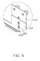
- FIG. 5is an enlarged view of the circled portion V of FIG. 2 .
- FIG. 6is an enlarged view of the circled portion VI of FIG. 3 .
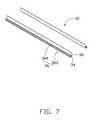
- FIG. 7is an enlarged view of the rails of FIG. 2 .
- FIG. 8is an enlarged view of the supports of FIG. 2 .
- an embodiment of a container data centerincludes a mobile container 10 , and a rack 20 .
- the container 10includes a top wall 12 , and a bottom wall 14 opposite to the top wall 12 .
- a receiving space 16is bounded by the top wall 12 and the bottom wall 14 .
- An inlet 18 communicating with the receiving space 16is bounded by corresponding ends of the top wall 12 and the bottom wall 14 .
- the container 10further includes two parallel rails 30 and two parallel supports 40 corresponding to the rails 30 .
- the rails 30are attached to an inner surface of the top wall 12 .
- the supports 40are attached to an inner surface of the bottom wall 14 , corresponding to the rails 30 .
- the rack 20is used to receive servers, power sources, heat dissipation devices, and includes a substantially rectangular top plate 22 , and a substantially rectangular bottom plate 24 opposite to the top plate 22 .
- a front side of the rack 20defines an opening 26 .
- the top plate 22includes a bracket 23 .
- the bracket 23includes a substantially rectangular-shaped base plate 230 attached to the top of the top plate 22 , two pairs of tabs 222 substantially perpendicularly extending up from opposite sides of the base plate 230 , and two pairs of first slide members 220 slidably mounted in the corresponding tabs 222 .
- Each tab 222defines a long first slide slot 2220 extending up and down.
- Each first slide member 220includes a fixing plate 223 , and three pulleys 224 substantially perpendicularly connected to the fixing plate 223 .
- the fixing plate 223defines two fixing holes (not show), and two fasteners 225 adjustably extend though the first slide slot 2220 and engage in the fixing holes of the fixing plate 223 to adjustably fasten the fixing plate 223 to the corresponding tab 222 .
- Two of the three pulleys 224are arranged on an upper portion of the fixing plate 223 along a line parallel to the base plate 230 , and the third pulley 224 is arranged under and between the two upper pulleys 224 .
- Each pulley 224defines a slide slot 2244 in a circumference of the pulley 224 . In this embodiment, the three pulleys 224 are arranged in a triangle.
- Each row of second slide members 240includes two second slide members 240 .
- the two rows of second slide members 240cooperatively form a rectangle, and each second slide member 240 is positioned at a corner of the rectangle.
- each second slide member 240is positioned at a corner of the bottom plate 24 .
- Each second slide member 240includes a bottom plate 241 mounted on the bottom plate 24 of the rack 20 , two tabs 242 substantially perpendicularly extending from opposite sides of the bottom plate 241 , and a pulley 246 rotatably mounted between the tabs 242 using an axel 2462 .
- Each pulley 246defines a slide slot 2464 in a circumference of the pulley 246 .
- each rail 30includes a fixing plate 32 substantially perpendicularly mounted to the top wall 12 , a connection plate 34 substantially perpendicularly extending from a distal side of the fixing plate 32 , and a slide rail 36 substantially perpendicularly extending from the connection plate 34 and parallel to the fixing plate 32 .
- the connection plate 34is connected to a center line of the slide rail 36 to divide the slide rail 36 into an upper slide rail 360 and a lower slide rail 362 .
- the fixing plate 32is mounted on the top wall 12 by welding.
- each support 40is substantially I-shaped and includes a lower support plate 42 , an upper support plate 44 opposite to the lower support plate 42 , and a plurality of connection plates 46 substantially perpendicularly connected between center lines of the lower and upper support plates 42 and 44 .
- the lower support plate 42is mounted on the bottom wall 14 .
- a slide rail 48longitudinally protrudes from the upper support plate 44 .
- the rack 20is installed in the receiving space 16 of the container 10 through the inlet 18 .
- the two rows of first slide members 220engage with the rail portions 30 , with the slide slots 2244 of the upper pulleys 224 of each first slide member 220 receiving the upper slide rail 360 of the corresponding rail 30 , and the slide slot 2244 of the lower pulley 224 of each first slide member 220 receiving the lower slide rail 362 of the corresponding rail 30 .
- the bottom plate 24 of the rack 20is supported by the supports 40 .
- the two rows of second slide members 240engage with the slide rails 48 , with the slide slot 2464 of each pulley 246 receiving the corresponding slide rail 48 .
- the rack 20is movably installed in the container 10 .
- the rack 20may be tightly fastened on the upper support plates 44 by a plurality of fasteners 50 , such as screws.
- the fasteners 50are removed and the rack 20 is moved forward to enlarge the space of the hot aisle.
Landscapes
- Engineering & Computer Science (AREA)
- Computer Hardware Design (AREA)
- General Engineering & Computer Science (AREA)
- Microelectronics & Electronic Packaging (AREA)
- Cooling Or The Like Of Electrical Apparatus (AREA)
- Drawers Of Furniture (AREA)
Abstract
Description
Claims (8)
Applications Claiming Priority (3)
| Application Number | Priority Date | Filing Date | Title |
|---|---|---|---|
| TW99137388A | 2010-11-01 | ||
| TW099137388ATW201221005A (en) | 2010-11-01 | 2010-11-01 | Container data center |
| TW99137388 | 2010-11-01 |
Publications (2)
| Publication Number | Publication Date |
|---|---|
| US20120104919A1 US20120104919A1 (en) | 2012-05-03 |
| US8371666B2true US8371666B2 (en) | 2013-02-12 |
Family
ID=45995926
Family Applications (1)
| Application Number | Title | Priority Date | Filing Date |
|---|---|---|---|
| US12/965,713Expired - Fee RelatedUS8371666B2 (en) | 2010-11-01 | 2010-12-10 | Container data center |
Country Status (2)
| Country | Link |
|---|---|
| US (1) | US8371666B2 (en) |
| TW (1) | TW201221005A (en) |
Cited By (8)
| Publication number | Priority date | Publication date | Assignee | Title |
|---|---|---|---|---|
| US20120155027A1 (en)* | 2010-12-16 | 2012-06-21 | Broome John P | Portable computer server enclosure |
| US20120162909A1 (en)* | 2010-12-24 | 2012-06-28 | Hon Hai Precision Industry Co., Ltd. | Container data center |
| US20130049558A1 (en)* | 2011-08-30 | 2013-02-28 | Hon Hai Precision Industry Co., Ltd. | Rack mechanism for server |
| US20150334866A1 (en)* | 2014-05-16 | 2015-11-19 | Dell Products, Lp | Modular Data Center Cabinet Rack Guide and Retention Mechanism |
| US9826833B2 (en)* | 2015-11-27 | 2017-11-28 | Ijang Industrial Co., Ltd. | Rack assembly and sub-rack thereof |
| US20200170140A1 (en)* | 2018-11-28 | 2020-05-28 | Doron Moshe | Securing Mechanism for Casing for Transporting Communications Computers and Electronics Racks |
| US11167908B2 (en)* | 2018-11-28 | 2021-11-09 | Doron Moshe | Securing mechanism for casing for transporting communications computers and electronics racks |
| US12331515B2 (en) | 2022-04-06 | 2025-06-17 | Hoffman Enclosures Inc. | Panel support and installation system |
Families Citing this family (11)
| Publication number | Priority date | Publication date | Assignee | Title |
|---|---|---|---|---|
| TW201218909A (en)* | 2010-10-29 | 2012-05-01 | Hon Hai Prec Ind Co Ltd | Container data center |
| TW201218908A (en)* | 2010-10-29 | 2012-05-01 | Hon Hai Prec Ind Co Ltd | Container data center and assembling method thereof |
| US20120200992A1 (en)* | 2011-02-07 | 2012-08-09 | Dell Products, Lp. | System and method for concurrent manufacturing, testing, and integration of a modular data center |
| TW201302018A (en)* | 2011-06-24 | 2013-01-01 | Hon Hai Prec Ind Co Ltd | Container data center |
| CN103429022B (en)* | 2012-05-23 | 2016-09-07 | 华为技术有限公司 | A kind of container data center |
| CN104679121B (en)* | 2013-11-29 | 2018-06-01 | 英业达科技有限公司 | Servomechanism |
| USD799869S1 (en) | 2015-12-18 | 2017-10-17 | Steelcase Inc. | Podium |
| US10667425B1 (en)* | 2016-09-26 | 2020-05-26 | Amazon Technologies, Inc. | Air containment and computing device mounting structure |
| US10908940B1 (en) | 2018-02-26 | 2021-02-02 | Amazon Technologies, Inc. | Dynamically managed virtual server system |
| US11490541B2 (en) | 2020-01-29 | 2022-11-01 | Daedalus Industrial Llc | Building management system container and skids |
| EP4142441B1 (en)* | 2021-08-30 | 2024-05-15 | Ovh | Rack system for a data center |
Citations (21)
| Publication number | Priority date | Publication date | Assignee | Title |
|---|---|---|---|---|
| US4023236A (en)* | 1974-10-21 | 1977-05-17 | Yoshida Kogyo Kabushiki Kaisha | Dual-roller support for overhung doors |
| US4138107A (en)* | 1977-03-25 | 1979-02-06 | Zbig Janis | Sports tethered ball practice device |
| US4993328A (en)* | 1988-08-22 | 1991-02-19 | Allor Manufacturing, Inc. | Trolley assembly |
| US5443312A (en)* | 1994-04-07 | 1995-08-22 | Schluter; Robert J. | Rack assembly for facilitating access to wall and cabinet-mounted serviceable equipment |
| US5967346A (en)* | 1997-04-18 | 1999-10-19 | Engineered Data Products, Incorporated | Supplemental storage rack system for expansion of storage capacity of high density storage rack system |
| US6027190A (en)* | 1995-09-07 | 2000-02-22 | Stewart; Edward C. | High density linear motion storage system |
| US6412892B1 (en)* | 1998-11-04 | 2002-07-02 | Fulterer Gesellschaft M.B.H. | Lateral guide for a cupboard slide-out system |
| US20030094884A1 (en)* | 2001-11-20 | 2003-05-22 | Sobol Norman N. | Modular storage system |
| US6688708B1 (en)* | 2000-02-29 | 2004-02-10 | Spacesaver Corporation | Stabilizing and enclosure system for mobile storage units |
| US20060001337A1 (en)* | 2004-07-01 | 2006-01-05 | Walburn William L | Laterally stablizing drawer slide for tall cupboard pull-out |
| US7042732B2 (en)* | 2003-12-29 | 2006-05-09 | Kuo-Chuan Hung | Flexible and rotatable wall-hanging operation box |
| US7257925B2 (en)* | 2002-07-26 | 2007-08-21 | Spacesaver Corporation | Floor-mounted rail for a mobile storage system |
| US20080190876A1 (en)* | 2005-05-04 | 2008-08-14 | Janson Steven L | Suspension-Type Storage Unit |
| US7475955B2 (en)* | 2001-04-02 | 2009-01-13 | Dressendorfer Michael R | Storage assembly for modules of varying sizes and improved shelving therefor |
| US20090179532A1 (en)* | 2008-01-15 | 2009-07-16 | Hui-Lan Pan | Cabinet assembly |
| US20100005998A1 (en)* | 2008-06-13 | 2010-01-14 | Production Resource Group L.L.C | Moving Trolley for an I Beam Extrusion |
| US7735190B2 (en)* | 2003-06-17 | 2010-06-15 | Metro Industries Inc. | Compact, modular storage system |
| US7832816B2 (en)* | 2005-06-28 | 2010-11-16 | Compagnucci Holding S.P.A. | Frame to support pull-out and rotating racks for cabinets |
| US8109581B1 (en)* | 2008-10-25 | 2012-02-07 | Lazenby James W | Method and apparatus for transparent shelves and drawers for kitchen cabinets |
| US20120104918A1 (en)* | 2010-10-29 | 2012-05-03 | Hon Hai Precision Industry Co., Ltd. | Data center |
| US20120104920A1 (en)* | 2010-10-29 | 2012-05-03 | Hon Hai Precision Industry Co., Ltd. | Container data center |
- 2010
- 2010-11-01TWTW099137388Apatent/TW201221005A/enunknown
- 2010-12-10USUS12/965,713patent/US8371666B2/ennot_activeExpired - Fee Related
Patent Citations (21)
| Publication number | Priority date | Publication date | Assignee | Title |
|---|---|---|---|---|
| US4023236A (en)* | 1974-10-21 | 1977-05-17 | Yoshida Kogyo Kabushiki Kaisha | Dual-roller support for overhung doors |
| US4138107A (en)* | 1977-03-25 | 1979-02-06 | Zbig Janis | Sports tethered ball practice device |
| US4993328A (en)* | 1988-08-22 | 1991-02-19 | Allor Manufacturing, Inc. | Trolley assembly |
| US5443312A (en)* | 1994-04-07 | 1995-08-22 | Schluter; Robert J. | Rack assembly for facilitating access to wall and cabinet-mounted serviceable equipment |
| US6027190A (en)* | 1995-09-07 | 2000-02-22 | Stewart; Edward C. | High density linear motion storage system |
| US5967346A (en)* | 1997-04-18 | 1999-10-19 | Engineered Data Products, Incorporated | Supplemental storage rack system for expansion of storage capacity of high density storage rack system |
| US6412892B1 (en)* | 1998-11-04 | 2002-07-02 | Fulterer Gesellschaft M.B.H. | Lateral guide for a cupboard slide-out system |
| US6688708B1 (en)* | 2000-02-29 | 2004-02-10 | Spacesaver Corporation | Stabilizing and enclosure system for mobile storage units |
| US7475955B2 (en)* | 2001-04-02 | 2009-01-13 | Dressendorfer Michael R | Storage assembly for modules of varying sizes and improved shelving therefor |
| US20030094884A1 (en)* | 2001-11-20 | 2003-05-22 | Sobol Norman N. | Modular storage system |
| US7257925B2 (en)* | 2002-07-26 | 2007-08-21 | Spacesaver Corporation | Floor-mounted rail for a mobile storage system |
| US7735190B2 (en)* | 2003-06-17 | 2010-06-15 | Metro Industries Inc. | Compact, modular storage system |
| US7042732B2 (en)* | 2003-12-29 | 2006-05-09 | Kuo-Chuan Hung | Flexible and rotatable wall-hanging operation box |
| US20060001337A1 (en)* | 2004-07-01 | 2006-01-05 | Walburn William L | Laterally stablizing drawer slide for tall cupboard pull-out |
| US20080190876A1 (en)* | 2005-05-04 | 2008-08-14 | Janson Steven L | Suspension-Type Storage Unit |
| US7832816B2 (en)* | 2005-06-28 | 2010-11-16 | Compagnucci Holding S.P.A. | Frame to support pull-out and rotating racks for cabinets |
| US20090179532A1 (en)* | 2008-01-15 | 2009-07-16 | Hui-Lan Pan | Cabinet assembly |
| US20100005998A1 (en)* | 2008-06-13 | 2010-01-14 | Production Resource Group L.L.C | Moving Trolley for an I Beam Extrusion |
| US8109581B1 (en)* | 2008-10-25 | 2012-02-07 | Lazenby James W | Method and apparatus for transparent shelves and drawers for kitchen cabinets |
| US20120104918A1 (en)* | 2010-10-29 | 2012-05-03 | Hon Hai Precision Industry Co., Ltd. | Data center |
| US20120104920A1 (en)* | 2010-10-29 | 2012-05-03 | Hon Hai Precision Industry Co., Ltd. | Container data center |
Cited By (12)
| Publication number | Priority date | Publication date | Assignee | Title |
|---|---|---|---|---|
| US20120155027A1 (en)* | 2010-12-16 | 2012-06-21 | Broome John P | Portable computer server enclosure |
| US8947879B2 (en)* | 2010-12-16 | 2015-02-03 | Smartcube, Llc | Portable computer server enclosure |
| US20150145391A1 (en)* | 2010-12-16 | 2015-05-28 | Smartcube, Llc | Portable computer server enclosure |
| US20120162909A1 (en)* | 2010-12-24 | 2012-06-28 | Hon Hai Precision Industry Co., Ltd. | Container data center |
| US20130049558A1 (en)* | 2011-08-30 | 2013-02-28 | Hon Hai Precision Industry Co., Ltd. | Rack mechanism for server |
| US8567883B2 (en)* | 2011-08-30 | 2013-10-29 | Hon Hai Precision Industry Co., Ltd. | Rack mechanism for server |
| US20150334866A1 (en)* | 2014-05-16 | 2015-11-19 | Dell Products, Lp | Modular Data Center Cabinet Rack Guide and Retention Mechanism |
| US9686882B2 (en)* | 2014-05-16 | 2017-06-20 | Dell Products, Lp | Modular data center cabinet rack guide and retention mechanism |
| US9826833B2 (en)* | 2015-11-27 | 2017-11-28 | Ijang Industrial Co., Ltd. | Rack assembly and sub-rack thereof |
| US20200170140A1 (en)* | 2018-11-28 | 2020-05-28 | Doron Moshe | Securing Mechanism for Casing for Transporting Communications Computers and Electronics Racks |
| US11167908B2 (en)* | 2018-11-28 | 2021-11-09 | Doron Moshe | Securing mechanism for casing for transporting communications computers and electronics racks |
| US12331515B2 (en) | 2022-04-06 | 2025-06-17 | Hoffman Enclosures Inc. | Panel support and installation system |
Also Published As
| Publication number | Publication date |
|---|---|
| US20120104919A1 (en) | 2012-05-03 |
| TW201221005A (en) | 2012-05-16 |
Similar Documents
| Publication | Publication Date | Title |
|---|---|---|
| US8371666B2 (en) | Container data center | |
| US8127940B2 (en) | Rail including a shelf for supporting an information handling system | |
| US12222779B2 (en) | Partial-width rack-mounted computing devices | |
| US8953326B2 (en) | Rack-mount server assembly | |
| US7823994B2 (en) | Server rack | |
| US20120104920A1 (en) | Container data center | |
| US20140153181A1 (en) | Rack-mount server assembly | |
| US9179572B2 (en) | Server | |
| US8356718B2 (en) | Server rack assembly | |
| US20130162125A1 (en) | Server cabinet | |
| CN201820172U (en) | rack server | |
| US20130026113A1 (en) | Server rack with lockable slide assembly | |
| US20110267761A1 (en) | Data storage assembly | |
| US7826210B2 (en) | Sliding front carriage for an information handling system chassis | |
| CN110139524B (en) | Machine cabinet | |
| US20110233349A1 (en) | Support frame | |
| US20150173508A1 (en) | Server cabinet | |
| US8437133B2 (en) | Latching module mounting system | |
| US20140263907A1 (en) | Hard disk drive mounting bracket | |
| US9131624B1 (en) | Rack-mountable IT device | |
| US8070433B2 (en) | Enclosure and heat dissipating device for the same | |
| US10271454B2 (en) | Sliding rail assemblies | |
| US20140285966A1 (en) | Server cabinet | |
| US20070012836A1 (en) | Mounting bracket for rack system and method of use | |
| US20120162909A1 (en) | Container data center |
Legal Events
| Date | Code | Title | Description |
|---|---|---|---|
| AS | Assignment | Owner name:HON HAI PRECISION INDUSTRY CO., LTD., TAIWAN Free format text:ASSIGNMENT OF ASSIGNORS INTEREST;ASSIGNOR:WU, HUI-FENG;REEL/FRAME:025473/0234 Effective date:20101101 | |
| STCF | Information on status: patent grant | Free format text:PATENTED CASE | |
| FPAY | Fee payment | Year of fee payment:4 | |
| AS | Assignment | Owner name:CLOUD NETWORK TECHNOLOGY SINGAPORE PTE. LTD., SINGAPORE Free format text:ASSIGNMENT OF ASSIGNORS INTEREST;ASSIGNOR:HON HAI PRECISION INDUSTRY CO., LTD.;REEL/FRAME:045281/0269 Effective date:20180112 Owner name:CLOUD NETWORK TECHNOLOGY SINGAPORE PTE. LTD., SING Free format text:ASSIGNMENT OF ASSIGNORS INTEREST;ASSIGNOR:HON HAI PRECISION INDUSTRY CO., LTD.;REEL/FRAME:045281/0269 Effective date:20180112 | |
| MAFP | Maintenance fee payment | Free format text:PAYMENT OF MAINTENANCE FEE, 8TH YEAR, LARGE ENTITY (ORIGINAL EVENT CODE: M1552); ENTITY STATUS OF PATENT OWNER: LARGE ENTITY Year of fee payment:8 | |
| FEPP | Fee payment procedure | Free format text:MAINTENANCE FEE REMINDER MAILED (ORIGINAL EVENT CODE: REM.); ENTITY STATUS OF PATENT OWNER: LARGE ENTITY | |
| LAPS | Lapse for failure to pay maintenance fees | Free format text:PATENT EXPIRED FOR FAILURE TO PAY MAINTENANCE FEES (ORIGINAL EVENT CODE: EXP.); ENTITY STATUS OF PATENT OWNER: LARGE ENTITY | |
| STCH | Information on status: patent discontinuation | Free format text:PATENT EXPIRED DUE TO NONPAYMENT OF MAINTENANCE FEES UNDER 37 CFR 1.362 | |
| FP | Lapsed due to failure to pay maintenance fee | Effective date:20250212 |