US8371443B2 - Biopsy marker delivery device - Google Patents
Biopsy marker delivery deviceDownload PDFInfo
- Publication number
- US8371443B2 US8371443B2US12/564,315US56431509AUS8371443B2US 8371443 B2US8371443 B2US 8371443B2US 56431509 AUS56431509 AUS 56431509AUS 8371443 B2US8371443 B2US 8371443B2
- Authority
- US
- United States
- Prior art keywords
- marker
- blocking member
- package component
- disposed
- hollow tube
- Prior art date
- Legal status (The legal status is an assumption and is not a legal conclusion. Google has not performed a legal analysis and makes no representation as to the accuracy of the status listed.)
- Active, expires
Links
- 239000003550markerSubstances0.000titleclaimsabstractdescription161
- 238000001574biopsyMethods0.000titleclaimsabstractdescription67
- 230000000903blocking effectEffects0.000claimsabstractdescription64
- 230000003213activating effectEffects0.000claimsdescription3
- 102000008186CollagenHuman genes0.000claimsdescription2
- 108010035532CollagenProteins0.000claimsdescription2
- 229920001436collagenPolymers0.000claimsdescription2
- 230000002028prematureEffects0.000abstractdescription6
- 210000001519tissueAnatomy0.000description12
- 238000000034methodMethods0.000description8
- 238000004806packaging method and processMethods0.000description8
- 229920002614Polyether block amidePolymers0.000description6
- TZCXTZWJZNENPQ-UHFFFAOYSA-Lbarium sulfateChemical compound[Ba+2].[O-]S([O-])(=O)=OTZCXTZWJZNENPQ-UHFFFAOYSA-L0.000description4
- 239000000463materialSubstances0.000description3
- 230000005855radiationEffects0.000description3
- 238000003466weldingMethods0.000description3
- 239000000853adhesiveSubstances0.000description2
- 230000001070adhesive effectEffects0.000description2
- 238000011503in vivo imagingMethods0.000description2
- 238000012986modificationMethods0.000description2
- 230000004048modificationEffects0.000description2
- 239000005022packaging materialSubstances0.000description2
- 239000000123paperSubstances0.000description2
- 239000004033plasticSubstances0.000description2
- 238000001356surgical procedureMethods0.000description2
- IAYPIBMASNFSPL-UHFFFAOYSA-NEthylene oxideChemical compoundC1CO1IAYPIBMASNFSPL-UHFFFAOYSA-N0.000description1
- 239000004775TyvekSubstances0.000description1
- 229920000690TyvekPolymers0.000description1
- 230000004913activationEffects0.000description1
- 230000006978adaptationEffects0.000description1
- 239000000654additiveSubstances0.000description1
- 230000000996additive effectEffects0.000description1
- 238000005452bendingMethods0.000description1
- 230000006835compressionEffects0.000description1
- 238000007906compressionMethods0.000description1
- 210000003811fingerAnatomy0.000description1
- 238000009459flexible packagingMethods0.000description1
- 238000003780insertionMethods0.000description1
- 230000037431insertionEffects0.000description1
- 239000007769metal materialSubstances0.000description1
- 239000012785packaging filmSubstances0.000description1
- 229920006280packaging filmPolymers0.000description1
- 229920000642polymerPolymers0.000description1
- 238000007789sealingMethods0.000description1
- 210000004872soft tissueAnatomy0.000description1
- 238000007920subcutaneous administrationMethods0.000description1
- 229920002725thermoplastic elastomerPolymers0.000description1
- 210000003813thumbAnatomy0.000description1
- 238000002604ultrasonographyMethods0.000description1
Images


Classifications
- A—HUMAN NECESSITIES
- A61—MEDICAL OR VETERINARY SCIENCE; HYGIENE
- A61B—DIAGNOSIS; SURGERY; IDENTIFICATION
- A61B90/00—Instruments, implements or accessories specially adapted for surgery or diagnosis and not covered by any of the groups A61B1/00 - A61B50/00, e.g. for luxation treatment or for protecting wound edges
- A61B90/39—Markers, e.g. radio-opaque or breast lesions markers
- A—HUMAN NECESSITIES
- A61—MEDICAL OR VETERINARY SCIENCE; HYGIENE
- A61B—DIAGNOSIS; SURGERY; IDENTIFICATION
- A61B10/00—Instruments for taking body samples for diagnostic purposes; Other methods or instruments for diagnosis, e.g. for vaccination diagnosis, sex determination or ovulation-period determination; Throat striking implements
- A61B10/02—Instruments for taking cell samples or for biopsy
- A61B10/0233—Pointed or sharp biopsy instruments
- A61B10/0266—Pointed or sharp biopsy instruments means for severing sample
- A61B10/0275—Pointed or sharp biopsy instruments means for severing sample with sample notch, e.g. on the side of inner stylet
- A—HUMAN NECESSITIES
- A61—MEDICAL OR VETERINARY SCIENCE; HYGIENE
- A61B—DIAGNOSIS; SURGERY; IDENTIFICATION
- A61B17/00—Surgical instruments, devices or methods
- A61B2017/00831—Material properties
- A61B2017/0084—Material properties low friction
- A61B2017/00845—Material properties low friction of moving parts with respect to each other
- A—HUMAN NECESSITIES
- A61—MEDICAL OR VETERINARY SCIENCE; HYGIENE
- A61B—DIAGNOSIS; SURGERY; IDENTIFICATION
- A61B90/00—Instruments, implements or accessories specially adapted for surgery or diagnosis and not covered by any of the groups A61B1/00 - A61B50/00, e.g. for luxation treatment or for protecting wound edges
- A61B90/39—Markers, e.g. radio-opaque or breast lesions markers
- A61B2090/3904—Markers, e.g. radio-opaque or breast lesions markers specially adapted for marking specified tissue
- A61B2090/3908—Soft tissue, e.g. breast tissue
- A—HUMAN NECESSITIES
- A61—MEDICAL OR VETERINARY SCIENCE; HYGIENE
- A61B—DIAGNOSIS; SURGERY; IDENTIFICATION
- A61B90/00—Instruments, implements or accessories specially adapted for surgery or diagnosis and not covered by any of the groups A61B1/00 - A61B50/00, e.g. for luxation treatment or for protecting wound edges
- A61B90/39—Markers, e.g. radio-opaque or breast lesions markers
- A61B2090/3987—Applicators for implanting markers
Definitions
- Biopsy sampleshave been obtained in a variety of ways in various medical procedures using a variety of devices.
- An exemplary biopsy deviceis the MAMMOTOME® brand device from Ethicon Endo-Surgery, Inc. of Cincinnati, Ohio. Biopsy devices may be used under stereotactic guidance, ultrasound guidance, MRI guidance, or otherwise.
- a biopsy siteit may be desirable to mark the location of a biopsy site for future reference. For instance, one or more markers may be deposited at a biopsy site before, during, or after a tissue sample is taken from the biopsy site.
- Exemplary marker deployment toolsinclude the MAMMOMARK®, MICROMARK®, and CORMARK® brand devices from Ethicon Endo-Surgery, Inc. of Cincinnati, Ohio.
- Further exemplary devices and methods for marking a biopsy siteare disclosed in U.S. Pub. No. 2005/0228311, entitled “Marker Device and Method of Deploying a Cavity Marker Using a Surgical Biopsy Device,” published Oct. 13, 2005; U.S. Pat. No. 6,996,433, entitled “Imageable Biopsy Site Marker,” issued Feb.
- a cannula type deployerinto the biopsy site, such as a flexible tubular deployer.
- the markershould not unintentionally fall out of the deployer, and the force to deploy the marker should not be excessive.
- U.S. patent application Ser. No. 12/196,301illustrates a biopsy marker deployment device that can include marker engaging element.
- the marker engaging elementcan be employed to prevent a marker from prematurely exiting the deployer tube.
- Applicanthas determined that in some instances, it may be desirable to prevent premature marker deployment without the use of marker engaging element such as shown in Ser. No. 12/196,301, and without use of features that may increase the force required to deploy a marker from a marker delivery device.
- Applicanthas recognized the desirability of preventing premature marker deployment without substantially adding to the force needed to deploy a marker. Additionally, Applicant has recognized the desirability of providing a marker blocking member that blocks marker deployment, such as while the delivery device is within a package.
- Applicanthas recognized the desirability of providing a marker blocking member that may be removed from the delivery device without activating the push rod or other deployment apparatus used to direct the markers from the marker tube. Accordingly, activation of the push rod can be accomplished without excessive force, and without the need to expel or otherwise move a member positioned in the tube distal of the biopsy marker (or biopsy markers if a plurality of markers are included in the tube).
- the present inventionprovides a biopsy marker deployer comprising a tube, a marker exit, and at least one marker disposed in the tube.
- a marker blocking memberis disposed in relation to the exit to prevent premature deployment of the marker (or markers) from the deployer.
- the blocking membermay be releasably inserted within the exit of the cannula, such that the blocking member is removable from the cannula without advancing a push rod or other deployment actuator associated with the marker delivery device.
- the blocking membermay include a proximal end and a distal end inclined with respect to the proximal end.
- the proximal end of the blocking membermay be disposed substantially at or distal of the proximal end of the exit through which the marker(s) are deployed from the cannula. For instance, at least half the length of the blocking member, and more particularly substantially the full length of the blocking member may be disposed distal of the proximal end of the exit.
- the distal facecan be disposed adjacent a ramp disposed in the deployer, the ramp positioned with respect to the marker exit for facilitating marker deployment through a side (lateral) marker exit.
- the inventionmay also provide an assembly comprising: an outer package; an inner package component disposed within the outer package; and a biopsy marker delivery device disposed within the outer package.
- the biopsy marker delivery devicemay comprise an elongate hollow tube, a side (lateral) marker exit, and at least one marker disposed within the tube and deployable from the tube through the marker exit.
- the delivery deviceincludes a marker blocking member disposed in the marker delivery device such that the blocking member prevents deployment of the at least one marker from the tube within the package.
- the marker blocking membermay be adapted to releasably engage the inner package component. Accordingly, the marker blocking member can act to prevent unintended marker deployment, and the marker blocking member can be removed from the marker delivery device without the need for actuating the delivery device. For instance, where the delivery device employs a push rod actuator or other marker pushing member, the marker blocking member is removed from the deployment tube when the marker is removed from the packaging, and without the need to advance or partially advance the push rod actuator.
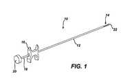
- FIG. 1depicts a perspective view of a marker delivery device of the type illustrated in U.S. patent application Ser. No. 12/196,301 filed Aug. 22, 2008;
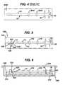
- FIG. 2depicts a cross-sectional view of a distal portion of a marker delivery device of the type illustrated in U.S. patent application Ser. No. 12/196,301 filed Aug. 22, 2008.
- FIG. 3depicts a marker being deployed from a deployer and through a lateral tissue receiving port in a biopsy needle to mark a biopsy site, such as illustrated in U.S. patent application Ser. No. 12/196,301 filed Aug. 22, 2008.
- FIG. 4depicts a prior art package component in the form of a cardboard mount supporting a biopsy marker deployer, where the tube of the deployer is held to the mount with one or more straps.
- FIG. 5depicts a marker deployment device and package component according to one embodiment of the present invention, illustrating the marker tube supported on a first portion of the package component and a marker blocking member including an anchor extending from the marker tube and engaging a second portion of the package component.
- FIG. 6illustrates an assembly according to one embodiment of the present invention, illustrating an outer package, an inner package component of the type shown in FIG. 5 , the inner package component disposed within the outer package, the inner package component including a first generally planar portion supporting the marker delivery device, and the inner package component including a second portion, such an integral tab extending from the first portion, where the marker delivery device includes a marker blocking member having an anchor portion extending from the marker tube and through an opening in the tab to releasably engaging the tab.
- FIG. 7is an enlarged illustration of the distal portion of a marker delivery and package component of FIG. 5 , with the marker delivery device shown in partial cross-section and illustrating the marker blocking member having a body portion disposed within the tube lumen, the body portion having a proximal face disposed substantially at or distal of the proximal end of the lateral marker exit, an inclined distal face positioned adjacent a ramp associated with the marker exit, and the marker blocking member having an anchor portion extending from the body portion, the anchor portion extending through the tab of the package component and releasably engaging the tab.
- FIG. 8is a perspective illustration of the distal portion of the marker delivery device including a blocking member.
- FIG. 9is a cross-sectional illustration according to an alternative embodiment, showing a biopsy device disposed in outer packaging, and illustrating a marker blocking member having a portion disposed in the deployer tube and a portion of the member extending radially from the tube and joined to a top cover portion of the outer packaging.
- FIGS. 1-3illustrate a marker delivery device 10 of the type illustrated in U.S. patent application Ser. No. 12/196,301 filed Aug. 22, 2008. The description below for FIGS. 1-3 is made for background purposes and with reference to the device shown in Ser. No. 12/196,301.
- FIG. 4illustrates a depiction of a prior art arrangement for supporting biopsy marker delivery device on a packaging component.
- FIG. 5-9illustrate one or more embodiments of a marker delivery device and assembly according to one or more embodiments of the present invention.
- marker delivery device 10may include a tubular elongate outer cannula 12 having a marker exit, such as side opening 14 formed near to, but which can be spaced proximally from, the distal end of the cannula 12 .
- a grip 16can be provided at the proximal end of cannula 12 .
- An actuatorsuch as pushing member in the form of a push rod 18 can be provided, with push rod 18 extending coaxially in cannula 12 such that the push rod 18 is configured to translate within cannula 12 to displace one or more markers through the side opening 14 (see FIG. 2 ).
- Rod 18can have a proximal portion having sufficient rigidity in compression to push a marker from the internal lumen of cannula 12 out through opening 14 , and include a more distal portion that is relatively flexible in bending so that the cannula 12 can be inserted along a curved path to deploy a marker element at a biopsy site.
- a plunger 20can be provided at the proximal end of rod 18 for forcing rod 18 distally in cannula 12 to deploy a marker out of the cannula 12 .
- a usermay grasp grip 16 with two fingers, and may push on plunger 20 using the thumb on the same hand, so that the marker delivery device 10 can be operated by a user's single hand.
- a spring (not shown) or other featuremay be provided about rod 18 to bias rod 18 proximally relative to grip 16 and cannula 12 .
- FIG. 2depicts a cross-sectional view of a distal portion of the marker delivery device 10 of FIG. 1 .
- FIG. 2shows a biopsy marker 300 disposed in the internal lumen 15 of the cannula 12 .
- the marker 300can comprise a biodegradable or otherwise resorbable body 306 , such as a generally cylindrically shaped body of collagen, and a metallic, generally radiopaque marker element 310 (shown in phantom) disposed within or otherwise carried by the body 306 .
- the cannula 12can be formed of any suitable metallic or non-metallic material.
- the cannula 12is formed of a thin walled flexible hollow tube formed of a suitable medical grade plastic or polymer.
- a suitable materialis a thermoplastic elastomer, such as Polyether block amide (PEBA), such as is known under the tradename PEBAX.
- PEBAXPolyether block amide
- the cannula 12can be formed of PEBAX, and can be substantially transparent to visible light and X-ray.
- the side opening 14can be formed by cutting away a portion of the wall of cannula 12 .
- the side opening 14communicates with an internal lumen 15 of the cannula.
- the side opening 14can extend axially (in a direction parallel to the axis of the lumen 15 ) from a proximal opening end 14 A to a distal opening end 14 B, as illustrated in FIG. 2 .
- a marker delivery devicecan have the distal end of the cannula 12 closed by a unitary endpiece 21 formed in place in the distal end of the cannula 12 , with a part of the endpiece 21 extending into the internal lumen 15 of the cannula.
- the distal endpiece 21can be a molded or cast component, and can provide an integrally formed combination of the tip 22 , a ramp 210 having a ramp surface 212 , and a marker engaging element 240 .
- the ramp surface 212aids in directing the marker 300 from the internal lumen 15 through side opening 14 .
- the marker engaging element 240(shown in FIG. 2 with thickness T) is described in the above Ser. No. 12/196,301.
- the element 240is generally not required for use with the present invention.
- the present inventionas described below with reference to FIGS. 5-9 , can be practiced without the need for the marker engaging element 240 .
- the tip 22can be formed of, or include, a material that is relatively more radiopaque than the wall of the cannula 12 .
- the endpiece 21can include a radiopaque additive, such as barium sulfate.
- the endpiece 21can be a component molded of PEBAX, with about 20 percent by weight barium sulfate added to the molten PEBAX mold composition.
- the marker delivery device 10may be used to deploy a marker to mark a particular location within a patient.
- a cannular biopsy needle 1000is shown.
- the needle 1000is shown having a closed distal end with piercing tip 1002 , and a lateral tissue receiving aperture 1014 .
- Marker deployer 10may be introduced to a biopsy site through biopsy needle 1000 , which can be the same needle used to collect a tissue sample from the biopsy site.
- the biopsy needle 1000can be of the type used with single insertion, multiple sample vacuum assisted biopsy devices. Several such biopsy devices are disclosed in the various patents and patent applications that have been referred to and incorporated by reference herein, though other biopsy devices may be used.
- FIG. 3shows the distal end of a marker deployer 10 disposed within the needle 1000 .
- the needle 1000can be positioned in tissue, and a biopsy sample can be obtained through opening 1014 , thereby providing a biopsy cavity adjacent opening 1014 .
- the deployer 10can be inserted into a proximal opening in the needle 1000 .
- the needle 1000 and deployer 10are positioned such that opening 14 of cannula 12 and opening 1014 of needle 1000 are substantially aligned axially and circumferentially.
- the push rod 18can be advanced to deploy the marker up the ramp surface 212 , through the opening 14 , and then through opening 1014 , into the biopsy cavity.
- FIG. 4illustrates a known arrangement for supporting a biopsy marker delivery device 10 on a package component 2000 .
- the package component 2000can be a piece of cardboard or stiff paper based material disposed within sterile packaging.
- the biopsy marker delivery device 10is shown fastened to the component 2000 by one or more straps 2010 , which can be in the form of elastic filaments or wires which may be cut or otherwise undone to release device 10 from component 2000 .
- FIG. 5illustrates a biopsy marker delivery device according to one embodiment of the present inventions.
- biopsy marker delivery device 10is supported on a package component 500 .
- the package component 500may comprise cardboard or generally stiff paper stock.
- Package component 500is shown including a generally planar portion 510 on which the device 10 is supported.
- FIG. 5illustrates members, such as straps 516 , for holding cannula 12 of the device on component 500 , and generally stationary with respect to planar portion 510 .
- the package component 500is shown further including a second portion labeled 520 .
- Second portion 520may be a tab formed by selectively cutting and folding part of generally planar portion 510 .
- the biopsy marker delivery deviceincludes a biopsy marker blocking member 400 disposed at least partially within the marker exit provided by side opening 14 .
- the blocking member 400is shown disposed in the cannula 12 , and is shown being at least partially visible in side opening 14 .
- Side opening 14provides the marker exit through which biopsy markers are deployed from cannula 12 .
- a marker exit at the distal end of cannula 12could be employed.
- the marker blocking member 400 shown in FIG. 5includes a first body portion, 410 , and a second anchor portion 420 .
- the body portion 410is disposed at least partially within the exit of cannula 12 .
- the second portion 420extends generally radially outward from the cannula 12 to extend through tab portion 520 of the package component 500 .
- the second portion 420can include an enlarged end 424 .
- the second portion 420can extend through an opening in the tab portion 520 , with the enlarged end 424 releasably engaging the tab portion 520 to maintain the body portion 410 of blocking member 400 in position with respect to the exit 14 and with respect to cannula 12 prior to use of the device 10 .
- FIG. 6illustrates the internal package component 500 and device 10 disposed within an outer package 560 .
- Outer package 560can include an upper cover 575 releasably joined to a lower package portion 570 .
- the package cover 575can be releasably joined to the lower package portion 570 in any suitable manner, such as but not limited to by adhesive means, by ultrasonic welding, by heat sealing, and the like.
- the cover 575 and lower portion 570may be made of similar, flexible packaging film stock.
- the lower portion 570is illustrated in the form of a tray having an upper perimeter 573 to which cover 575 is releasably attached, and the lower portion 570 may also include sidewalls 574 and a bottom floor 572 on which the component 500 may be supported.
- the tab portion 520is shown extending generally vertically from and substantially perpendicular to the planar portion 510 .
- An opening 524 cut (or otherwise formed) in tab portion 510is sized to be slightly smaller in one dimension than a corresponding dimension of enlarged head 424 . Accordingly, with cannula 12 held in place by members 516 , and with the blocking member 400 held in place with respect to cannula 12 by the engagement of anchor portion 420 with tab 520 , the blocking member 400 can be employed to prevent premature release of marker elements from the lumen of cannula 12 .
- FIG. 7provides an enlarged illustration of the distal portion of a marker delivery device 10 and package component of FIG. 5 , with the marker delivery device shown in partial cross-section and illustrating the marker blocking member 400 having a body portion 410 disposed within the exit 14 of tube lumen 15 .
- two biopsy markers labeled 300 A and 300 Bare shown positioned within cannula lumen 15 proximal of the blocking member 400 .
- the body portion 410is illustrated having a proximal face 414 disposed substantially at or distal of the proximal end 14 A of the marker exit 14 .
- the body portion 410is also shown having an inclined distal face 412 positioned adjacent to and facing the inclined surface of the ramp 212 associated with the marker exit.
- the body portion 410may be sized and shaped to fit the space in lumen 15 bounded by (or otherwise defined by): the inclined ramp surface 212 ; the inner diameter of cannula 12 ; and an imaginary plane passing through the proximal end 14 A of exit 14 and extending generally perpendicular to the axis of lumen 15 . Accordingly, blocking member 400 may be removed from device 10 in a generally radially outward direction, without the need to advance the push rod, and without the need to translate the blocking member (or markers 300 ) in an axial direction.
- Anchor portion 420 of blocking member 400is shown extending in a generally radially outward direction from body 410 , to extend from the marker exit 14 of cannula 12 .
- the anchor portion 420is shown including a neck 421 extending through the tab portion 520 of package component 500 (such as through opening 524 in the tab 520 , the opening 524 illustrated in FIG. 8 ).
- the end 424 of the anchor portionis enlarged relative to the neck 421 , and the enlarged end 424 may be sized to have a length that is larger than one dimension (e.g. width) of the opening 524 , and smaller than another dimension (e.g. length) of the opening 524 , so that the enlarged end 424 may be inserted through opening 524 and is adapted to releasably engage the tab 520 .
- one dimensione.g. width
- another dimensione.g. length
- FIG. 8is a perspective illustration of the distal portion of the marker delivery device comprising marker blocking member 400 .
- FIG. 8illustrates the tab 520 with opening 524 through which anchor portion 520 extends.
- tab 520is depicted as being generally perpendicular to planar component 510 . However, if desired, tab 520 may bent or otherwise formed to at least partially overly the portion of the device 10 including the exit 14 , and the tab may assist in holding the device 10 against the package component 500 .
- FIG. 9provides a cross-sectional illustration of an alternative embodiment, with biopsy device 10 shown disposed in outer packaging 560 , and with the blocking member 400 connected to releasable top cover 575 . Accordingly, removal of upper cover 575 from lower package portion 570 also serves to remove blocking member 400 from biopsy device 10 .
- the blocking memberis shown having a connector portion 422 that is attached to upper cover 575 .
- the blocking member 400may be attached to cover 575 in any suitable manner, including but not limited to by use of adhesive attachment, heat welding, ultrasonic welding, and the like.
- Embodiments of the devices disclosed hereinare generally designed to be disposed of after a single use, but could be designed to be used multiple times.
- the packaging materialsmay be any suitable packaging materials, such as plastic or TYVEK bag.
- the packaged biopsy devicemay then be placed in a field of radiation such as gamma radiation, x-rays, or high-energy electrons to sterilize the device and packaging.
- a devicemay also be sterilized using any other technique known in the art, including but not limited to beta or gamma radiation, ethylene oxide, or steam.
Landscapes
- Health & Medical Sciences (AREA)
- Surgery (AREA)
- Life Sciences & Earth Sciences (AREA)
- Heart & Thoracic Surgery (AREA)
- Pathology (AREA)
- Oral & Maxillofacial Surgery (AREA)
- Engineering & Computer Science (AREA)
- Biomedical Technology (AREA)
- Nuclear Medicine, Radiotherapy & Molecular Imaging (AREA)
- Medical Informatics (AREA)
- Molecular Biology (AREA)
- Animal Behavior & Ethology (AREA)
- General Health & Medical Sciences (AREA)
- Public Health (AREA)
- Veterinary Medicine (AREA)
- Surgical Instruments (AREA)
Abstract
Description
Claims (20)
Priority Applications (1)
| Application Number | Priority Date | Filing Date | Title |
|---|---|---|---|
| US12/564,315US8371443B2 (en) | 2009-09-22 | 2009-09-22 | Biopsy marker delivery device |
Applications Claiming Priority (1)
| Application Number | Priority Date | Filing Date | Title |
|---|---|---|---|
| US12/564,315US8371443B2 (en) | 2009-09-22 | 2009-09-22 | Biopsy marker delivery device |
Publications (2)
| Publication Number | Publication Date |
|---|---|
| US20110071424A1 US20110071424A1 (en) | 2011-03-24 |
| US8371443B2true US8371443B2 (en) | 2013-02-12 |
Family
ID=43757237
Family Applications (1)
| Application Number | Title | Priority Date | Filing Date |
|---|---|---|---|
| US12/564,315Active2030-10-22US8371443B2 (en) | 2009-09-22 | 2009-09-22 | Biopsy marker delivery device |
Country Status (1)
| Country | Link |
|---|---|
| US (1) | US8371443B2 (en) |
Cited By (15)
| Publication number | Priority date | Publication date | Assignee | Title |
|---|---|---|---|---|
| WO2017083412A1 (en) | 2015-11-11 | 2017-05-18 | Devicor Medical Products, Inc. | Marker delivery device and method of deploying a marker |
| WO2017083417A1 (en) | 2015-11-12 | 2017-05-18 | Devicor Medical Products, Inc. | Marker delivery device and method of deploying a marker |
| US9788819B2 (en) | 2014-05-01 | 2017-10-17 | Devicor Medical Products, Inc. | Introducer for biopsy device |
| US9877706B2 (en) | 2013-03-15 | 2018-01-30 | Devicor Medical Products, Inc. | Biopsy device |
| US20180140288A1 (en)* | 2015-05-06 | 2018-05-24 | Devicor Medical Products, Inc. | Marker delivery device for use with mri breast biopsy system |
| US10064607B2 (en) | 2013-08-28 | 2018-09-04 | Devicor Medical Products, Inc. | Tissue collection assembly for biopsy device |
| US10258316B2 (en) | 2011-06-23 | 2019-04-16 | Devicor Medical Products, Inc. | Introducer for biopsy device |
| US10314563B2 (en) | 2014-11-26 | 2019-06-11 | Devicor Medical Products, Inc. | Graphical user interface for biopsy device |
| US10335124B1 (en) | 2016-02-29 | 2019-07-02 | Devicor Medical Products, Inc. | Marker delivery device with adaptor for biopsy site marking and method of use thereof |
| US10610205B2 (en) | 2014-05-15 | 2020-04-07 | Devicor Medical Products, Inc. | Biopsy device |
| US10683119B2 (en) | 2014-05-23 | 2020-06-16 | Merit Medical Systems, Inc. | Marker element, device for making a marker element, and method for making a marker element |
| US10869653B2 (en) | 2015-10-30 | 2020-12-22 | Devicor Medical Products, Inc. | Tissue sample holder with bulk tissue collection feature |
| US11179141B2 (en) | 2006-12-13 | 2021-11-23 | Devicor Medical Products, Inc. | Biopsy system |
| US11207059B2 (en) | 2015-07-29 | 2021-12-28 | Devicor Medical Products, Inc. | Biopsy imaging rod with an egress port, with a biopsy marker and with a biased pushrod |
| US11324490B2 (en) | 2010-09-10 | 2022-05-10 | Devicor Medical Products, Inc. | Biopsy device tissue sample holder with removable tray |
Families Citing this family (11)
| Publication number | Priority date | Publication date | Assignee | Title |
|---|---|---|---|---|
| CA2757870C (en)* | 2009-04-30 | 2016-02-02 | Cook Medical Technologies Llc | System and method for fiducial deployment |
| US8838208B2 (en) | 2011-06-28 | 2014-09-16 | Cook Medical Technologies Llc | Fiducial deployment needle system |
| US8938285B2 (en) | 2011-08-08 | 2015-01-20 | Devicor Medical Products, Inc. | Access chamber and markers for biopsy device |
| USD695404S1 (en) | 2011-09-07 | 2013-12-10 | Devicor Medical Products, Inc. | Biopsy device |
| CA2868396C (en)* | 2012-05-24 | 2020-06-16 | Takeda Nycomed As | Packaging containing a form-stable coiled hemostatic collagen carrier |
| US9522264B2 (en) | 2013-02-26 | 2016-12-20 | Cook Medical Technologies Llc | Ratchet-slide handle and system for fiducial deployment |
| EP2996570B1 (en)* | 2013-03-15 | 2018-12-26 | Devicor Medical Products, Inc. | Biopsy site marker applier |
| EP3151764B1 (en) | 2014-06-09 | 2023-02-01 | Cook Medical Technologies LLC | Screw-driven handles and systems for fiducial deployment |
| JP6302573B2 (en) | 2014-06-16 | 2018-03-28 | クック・メディカル・テクノロジーズ・リミテッド・ライアビリティ・カンパニーCook Medical Technologies Llc | Plunger-driven collet handle and fiducial deployment system |
| KR20170093137A (en) | 2014-11-06 | 2017-08-14 | 데비코어 메디컬 프로덕츠, 인코포레이티드 | Spring-ejected biopsy marker |
| AU2015355303B2 (en) | 2014-12-03 | 2018-11-01 | Cook Medical Technologies Llc | Endoscopic ultrasound fiducial needle stylet handle assembly |
Citations (17)
| Publication number | Priority date | Publication date | Assignee | Title |
|---|---|---|---|---|
| US4760847A (en)* | 1986-08-18 | 1988-08-02 | Vincent Vaillancourt | Depth measuring device |
| US5526822A (en) | 1994-03-24 | 1996-06-18 | Biopsys Medical, Inc. | Method and apparatus for automated biopsy and collection of soft tissue |
| US5941439A (en)* | 1997-05-14 | 1999-08-24 | Mitek Surgical Products, Inc. | Applicator and method for deploying a surgical fastener in tissue |
| US6086544A (en) | 1999-03-31 | 2000-07-11 | Ethicon Endo-Surgery, Inc. | Control apparatus for an automated surgical biopsy device |
| US6200274B1 (en)* | 1997-07-17 | 2001-03-13 | Minrad Inc. | Removable needle rule |
| US6228055B1 (en) | 1994-09-16 | 2001-05-08 | Ethicon Endo-Surgery, Inc. | Devices for marking and defining particular locations in body tissue |
| US6371904B1 (en) | 1998-12-24 | 2002-04-16 | Vivant Medical, Inc. | Subcutaneous cavity marking device and method |
| US20030109803A1 (en) | 2001-11-01 | 2003-06-12 | Huitema Thomas W. | MRI compatible surgical biopsy device |
| US20030233101A1 (en)* | 2002-06-17 | 2003-12-18 | Senorx, Inc. | Plugged tip delivery tube for marker placement |
| US20040124105A1 (en)* | 2002-12-30 | 2004-07-01 | Keith Seiler | Packaged systems for implanting markers in a patient and methods for manufacturing and using such systems |
| US20040236213A1 (en)* | 2003-05-23 | 2004-11-25 | Senorx, Inc. | Marker delivery device with releasable plug |
| US20050119562A1 (en)* | 2003-05-23 | 2005-06-02 | Senorx, Inc. | Fibrous marker formed of synthetic polymer strands |
| US20050228311A1 (en) | 2004-03-31 | 2005-10-13 | Beckman Andrew T | Marker device and method of deploying a cavity marker using a surgical biopsy device |
| US6993375B2 (en) | 1999-02-02 | 2006-01-31 | Senorx, Inc. | Tissue site markers for in vivo imaging |
| US6996433B2 (en) | 1999-02-02 | 2006-02-07 | Senorx, Inc. | Imageable biopsy site marker |
| US20070010738A1 (en) | 2004-10-14 | 2007-01-11 | Mark Joseph L | Surgical site marker delivery system |
| US20070118048A1 (en) | 2000-10-13 | 2007-05-24 | Stephens Randy R | Remote thumbwheel for a surgical biopsy device |
- 2009
- 2009-09-22USUS12/564,315patent/US8371443B2/enactiveActive
Patent Citations (21)
| Publication number | Priority date | Publication date | Assignee | Title |
|---|---|---|---|---|
| US4760847A (en)* | 1986-08-18 | 1988-08-02 | Vincent Vaillancourt | Depth measuring device |
| US5526822A (en) | 1994-03-24 | 1996-06-18 | Biopsys Medical, Inc. | Method and apparatus for automated biopsy and collection of soft tissue |
| US7229417B2 (en) | 1994-09-16 | 2007-06-12 | Ethicon Endo-Surgery, Inc. | Methods for marking a biopsy site |
| US6228055B1 (en) | 1994-09-16 | 2001-05-08 | Ethicon Endo-Surgery, Inc. | Devices for marking and defining particular locations in body tissue |
| US7044957B2 (en) | 1994-09-16 | 2006-05-16 | Ethicon Endo-Surgery, Inc. | Devices for defining and marking tissue |
| US5941439A (en)* | 1997-05-14 | 1999-08-24 | Mitek Surgical Products, Inc. | Applicator and method for deploying a surgical fastener in tissue |
| US6200274B1 (en)* | 1997-07-17 | 2001-03-13 | Minrad Inc. | Removable needle rule |
| US6371904B1 (en) | 1998-12-24 | 2002-04-16 | Vivant Medical, Inc. | Subcutaneous cavity marking device and method |
| US6996433B2 (en) | 1999-02-02 | 2006-02-07 | Senorx, Inc. | Imageable biopsy site marker |
| US6993375B2 (en) | 1999-02-02 | 2006-01-31 | Senorx, Inc. | Tissue site markers for in vivo imaging |
| US7047063B2 (en) | 1999-02-02 | 2006-05-16 | Senorx, Inc. | Tissue site markers for in vivo imaging |
| US6086544A (en) | 1999-03-31 | 2000-07-11 | Ethicon Endo-Surgery, Inc. | Control apparatus for an automated surgical biopsy device |
| US20070118048A1 (en) | 2000-10-13 | 2007-05-24 | Stephens Randy R | Remote thumbwheel for a surgical biopsy device |
| US20030109803A1 (en) | 2001-11-01 | 2003-06-12 | Huitema Thomas W. | MRI compatible surgical biopsy device |
| US20030233101A1 (en)* | 2002-06-17 | 2003-12-18 | Senorx, Inc. | Plugged tip delivery tube for marker placement |
| US20040124105A1 (en)* | 2002-12-30 | 2004-07-01 | Keith Seiler | Packaged systems for implanting markers in a patient and methods for manufacturing and using such systems |
| US20040236213A1 (en)* | 2003-05-23 | 2004-11-25 | Senorx, Inc. | Marker delivery device with releasable plug |
| US20040236212A1 (en)* | 2003-05-23 | 2004-11-25 | Senorx, Inc. | Fibrous marker and intracorporeal delivery thereof |
| US20050119562A1 (en)* | 2003-05-23 | 2005-06-02 | Senorx, Inc. | Fibrous marker formed of synthetic polymer strands |
| US20050228311A1 (en) | 2004-03-31 | 2005-10-13 | Beckman Andrew T | Marker device and method of deploying a cavity marker using a surgical biopsy device |
| US20070010738A1 (en) | 2004-10-14 | 2007-01-11 | Mark Joseph L | Surgical site marker delivery system |
Cited By (20)
| Publication number | Priority date | Publication date | Assignee | Title |
|---|---|---|---|---|
| US11179141B2 (en) | 2006-12-13 | 2021-11-23 | Devicor Medical Products, Inc. | Biopsy system |
| US11324490B2 (en) | 2010-09-10 | 2022-05-10 | Devicor Medical Products, Inc. | Biopsy device tissue sample holder with removable tray |
| US10258316B2 (en) | 2011-06-23 | 2019-04-16 | Devicor Medical Products, Inc. | Introducer for biopsy device |
| US10413280B2 (en) | 2013-03-15 | 2019-09-17 | Devicor Medical Products, Inc. | Biopsy device |
| US9877706B2 (en) | 2013-03-15 | 2018-01-30 | Devicor Medical Products, Inc. | Biopsy device |
| US10064607B2 (en) | 2013-08-28 | 2018-09-04 | Devicor Medical Products, Inc. | Tissue collection assembly for biopsy device |
| US9788819B2 (en) | 2014-05-01 | 2017-10-17 | Devicor Medical Products, Inc. | Introducer for biopsy device |
| US10610205B2 (en) | 2014-05-15 | 2020-04-07 | Devicor Medical Products, Inc. | Biopsy device |
| US11564668B2 (en) | 2014-05-15 | 2023-01-31 | Devicor Medical Products, Inc. | Biopsy device |
| US10683119B2 (en) | 2014-05-23 | 2020-06-16 | Merit Medical Systems, Inc. | Marker element, device for making a marker element, and method for making a marker element |
| US10314563B2 (en) | 2014-11-26 | 2019-06-11 | Devicor Medical Products, Inc. | Graphical user interface for biopsy device |
| US10646208B2 (en)* | 2015-05-06 | 2020-05-12 | Devicor Medical Products, Inc. | Marker delivery device for use with MRI breast biopsy system |
| US20180140288A1 (en)* | 2015-05-06 | 2018-05-24 | Devicor Medical Products, Inc. | Marker delivery device for use with mri breast biopsy system |
| US11207059B2 (en) | 2015-07-29 | 2021-12-28 | Devicor Medical Products, Inc. | Biopsy imaging rod with an egress port, with a biopsy marker and with a biased pushrod |
| US10869653B2 (en) | 2015-10-30 | 2020-12-22 | Devicor Medical Products, Inc. | Tissue sample holder with bulk tissue collection feature |
| WO2017083412A1 (en) | 2015-11-11 | 2017-05-18 | Devicor Medical Products, Inc. | Marker delivery device and method of deploying a marker |
| US11571273B2 (en) | 2015-11-11 | 2023-02-07 | Devicor Medical Products, Inc. | Marker delivery device and method of deploying a marker |
| WO2017083417A1 (en) | 2015-11-12 | 2017-05-18 | Devicor Medical Products, Inc. | Marker delivery device and method of deploying a marker |
| US11364089B2 (en) | 2015-11-12 | 2022-06-21 | Devicor Medical Products, Inc. | Marker delivery device and method of deploying a marker |
| US10335124B1 (en) | 2016-02-29 | 2019-07-02 | Devicor Medical Products, Inc. | Marker delivery device with adaptor for biopsy site marking and method of use thereof |
Also Published As
| Publication number | Publication date |
|---|---|
| US20110071424A1 (en) | 2011-03-24 |
Similar Documents
| Publication | Publication Date | Title |
|---|---|---|
| US8371443B2 (en) | Biopsy marker delivery device | |
| US8532747B2 (en) | Biopsy marker delivery device | |
| US8241299B2 (en) | Biopsy marker delivery configured to retain marker prior to intended deployment | |
| US10874841B2 (en) | Biopsy site marker applier | |
| US20110071391A1 (en) | Biopsy marker delivery device with positioning component | |
| KR101851924B1 (en) | Introducer for biopsy device | |
| EP2092893B1 (en) | Biopsy site marker applier | |
| US8068895B2 (en) | Biopsy site marker deployment instrument | |
| US8079964B2 (en) | Method and apparatus for inserting biopsy site marker in marker body | |
| US20110071423A1 (en) | Flexible biopsy marker delivery device | |
| US8050742B2 (en) | Biopsy device | |
| US20110218433A1 (en) | Biopsy Marker Delivery Device | |
| CN117958999A (en) | Method and apparatus for direct marking | |
| US20100049085A1 (en) | Method of making a biopsy marker delivery device | |
| EP3373840B1 (en) | Marker delivery device | |
| HK1222783B (en) | Biopsy site marker applier |
Legal Events
| Date | Code | Title | Description |
|---|---|---|---|
| AS | Assignment | Owner name:ETHICON ENDO-SURGERY, INC., OHIO Free format text:ASSIGNMENT OF ASSIGNORS INTEREST;ASSIGNORS:NOCK, ANDREW P.;RAMOS, RAMON;PARIHAR, SHAILENDRA K.;REEL/FRAME:023418/0915 Effective date:20091006 | |
| AS | Assignment | Owner name:DEVICOR MEDICAL PRODUCTS, INC., WISCONSIN Free format text:ASSIGNMENT OF ASSIGNORS INTEREST;ASSIGNOR:ETHICON ENDO-SURGERY, INC.;REEL/FRAME:024656/0606 Effective date:20100709 | |
| AS | Assignment | Owner name:GENERAL ELECTRIC CAPITAL CORPORATION, AS AGENT, MA Free format text:SECURITY AGREEMENT;ASSIGNOR:DEVICOR MEDICAL PRODUCTS, INC.;REEL/FRAME:024672/0088 Effective date:20100709 | |
| STCF | Information on status: patent grant | Free format text:PATENTED CASE | |
| CC | Certificate of correction | ||
| FEPP | Fee payment procedure | Free format text:PAYOR NUMBER ASSIGNED (ORIGINAL EVENT CODE: ASPN); ENTITY STATUS OF PATENT OWNER: LARGE ENTITY | |
| FPAY | Fee payment | Year of fee payment:4 | |
| MAFP | Maintenance fee payment | Free format text:PAYMENT OF MAINTENANCE FEE, 8TH YEAR, LARGE ENTITY (ORIGINAL EVENT CODE: M1552); ENTITY STATUS OF PATENT OWNER: LARGE ENTITY Year of fee payment:8 | |
| MAFP | Maintenance fee payment | Free format text:PAYMENT OF MAINTENANCE FEE, 12TH YEAR, LARGE ENTITY (ORIGINAL EVENT CODE: M1553); ENTITY STATUS OF PATENT OWNER: LARGE ENTITY Year of fee payment:12 |