US8371237B2 - Computer work station with moveable monitor support - Google Patents
Computer work station with moveable monitor supportDownload PDFInfo
- Publication number
- US8371237B2 US8371237B2US12/509,943US50994309AUS8371237B2US 8371237 B2US8371237 B2US 8371237B2US 50994309 AUS50994309 AUS 50994309AUS 8371237 B2US8371237 B2US 8371237B2
- Authority
- US
- United States
- Prior art keywords
- worksurface
- workstation
- base
- primary
- front portion
- Prior art date
- Legal status (The legal status is an assumption and is not a legal conclusion. Google has not performed a legal analysis and makes no representation as to the accuracy of the status listed.)
- Active, expires
Links
Images


Classifications
- A—HUMAN NECESSITIES
- A47—FURNITURE; DOMESTIC ARTICLES OR APPLIANCES; COFFEE MILLS; SPICE MILLS; SUCTION CLEANERS IN GENERAL
- A47B—TABLES; DESKS; OFFICE FURNITURE; CABINETS; DRAWERS; GENERAL DETAILS OF FURNITURE
- A47B21/00—Tables or desks for office equipment, e.g. typewriters, keyboards
- A47B21/03—Tables or desks for office equipment, e.g. typewriters, keyboards with substantially horizontally extensible or adjustable parts other than drawers, e.g. leaves
- A47B21/0314—Platforms for supporting office equipment
Definitions
- the present inventionrelates generally to a computer work station, and in particular, to a computer work station having a moveable monitor support.
- Workstationscan be configured with a monitor support that is moveably supported by a worksurface. In such workstations, the user can adjust the position of the monitor to accommodate their particular needs, for example when reclining in a chair. Other workstations are configured with a moveable worksurface. Again, the user can adjust the position of the worksurface to accommodate their particular needs.
- Some workstationscan be configured with multiple support members that are moveable relative to each other. Typically, in such systems, the user must separately adjust each of the support members. In addition, the user may be required to actuate one or more locking or adjustment mechanisms for each component being moved once a desired location is achieved. In other configurations, two or more worksurfaces may be coupled together so as to automatically move with each other. Typically, however, such systems are configured with relatively complicated and expensive mechanisms, and are not portable or capable of being configured for use with, or on top of, a traditional worksurface such as a desk.
- one embodiment of a workstationincludes a monitor support adapted to be move ably supported by a primary worksurface, wherein the monitor support is moveable between a first position and a second position.
- An auxiliary worksurfaceis pivotally connected to the monitor support about a horizontal axis, and is adapted to be moveably supported by the primary worksurface.
- the auxiliary worksurfaceis automatically moveable with the monitor support from a first worksurface position to a second worksurface position, with the auxiliary worksurface pivoting downwardly as the auxiliary worksurface is moved from the first worksurface position to the second worksurface position.
- the auxiliary worksurfaceincludes a bottom with a downwardly facing recess shaped to receive an edge portion of the primary worksurface as the auxiliary worksurface is moved from the first worksurface position to the second worksurface position and pivots about the horizontal axis.
- one embodiment of the workstationincludes a base member adapted to be supported on a primary worksurface.
- the base memberincludes a releasable attachment mechanism adapted to releasably secure the base member to the primary worksurface.
- a monitor supportis moveably supported by the base member and is moveable between a first position and a second position.
- An auxiliary worksurfaceis pivotally connected to the monitor support about a horizontal axis and is moveably supported by the base member. The auxiliary worksurface is automatically moveable with the monitor support from a first worksurface position to a second worksurface position, with the auxiliary worksurface pivoting downwardly as the auxiliary worksurface is moved from said first worksurface position to said second worksurface position.
- one embodiment of a workstationin another aspect, includes a base member adapted to be supported on a primary worksurface.
- the base memberincludes a releasable attachment mechanism adapted to releasably secure the base member to the primary worksurface.
- a worksurfaceincludes a rear portion and a front portion, with the worksurface moveable between a first position and a second position. The front portion is automatically downwardly pivotable relative to the rear portion as the worksurface is moved between the first and second positions.
- At least one link memberhas a first end pivotally connected to the base about a pivot axis and a second end pivotally and translatably connected to the front portion.
- a method for configuring a workspaceincludes providing a portable workstation having a base, a monitor support moveably coupled to the base and an auxiliary worksurface moveably coupled to the base, with the auxiliary worksurface being pivotable relative to the monitor support.
- the methodfurther includes releasably securing the base to a primary worksurface, moving the monitor support from a first to second position, and automatically moving the auxiliary worksurface with the monitor support from a first worksurface position to a second worksurface position, and thereby pivoting the auxiliary worksurface downwardly about a horizontal axis.
- the various embodiments of the workstation, and methods of configuring a workstationprovide significant advantages over other workstations.
- movement of either the monitor support or auxiliary worksurfacecauses the other thereof to move.
- the usercan simply and easily adjust one of the monitor support or auxiliary worksurface, with the other following to a predetermined position so as to avoid multiple adjustments by the user.
- the auxiliary worksurfacepivots as it moves toward the user, such that it moves with and is positioned for use by a user as they tilt rearwardly in a chair, for example.
- the workstationis relatively portable, and is configured and adapted to be quickly and securely coupled to a primary worksurface, such as a desk or table.
- a primary worksurfacecan be easily configured to provide the user with an ergonomic workstation, while allowing for the primary worksurface to be returned to its conventional state for other tasks.
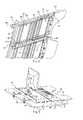
- FIG. 1is a perspective view of a workstation secured to a primary worksurface.
- FIG. 2is a side view schematic showing a user in an upright position using the workstation in a retracted position.
- FIG. 3is a side view schematic showing a user in a reclined position using the workstation in an extended position.
- FIG. 4is a front perspective view of the workstation shown in FIG. 1 with a monitor support and keyboard situated thereon in an extended position.
- FIG. 5is a rear perspective view of the workstation shown in FIG. 1 with a monitor support and keyboard situated thereon in an extended position.
- FIG. 6is a rear perspective view of the workstation shown in FIG. 1 with a monitor support and keyboard situated thereon in a retracted position.
- FIG. 7is a top perspective view of a base, hinge and arm support.
- FIG. 8is a bottom perspective view of the workstation shown in FIG. 1 .
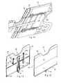
- FIG. 9is a perspective view of a second embodiment of a workstation releasably secured to a primary worksurface.
- FIG. 10is a perspective view of a base of the second embodiment of the workstation shown in FIG. 9 as secured to a primary worksurface.
- FIG. 11is a bottom perspective view of the workstation shown in FIG. 9 .
- FIG. 12is a perspective view of a third embodiment of a workstation releasably secured to a primary worksurface.
- FIG. 13is a perspective view of a base of the third embodiment of the workstation shown in FIG. 12 as secured to a primary worksurface.
- FIG. 14is a bottom perspective view of the workstation shown in FIG. 12 .
- FIG. 15is a bottom perspective view of a fourth embodiment of the workstation.
- FIG. 16is a top perspective view of the workstation shown in FIG. 15 .
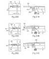
- FIG. 17is an enlarged side view of a track member.
- FIG. 18is perspective view of a guide member.
- FIG. 19is a side view of the guide member shown in FIG. 18 .
- FIGS. 20A-Cshow views of a fourth embodiment of a workstation in a retracted, intermediate and extended position respectively.
- FIGS. 21A-Cshow enlarged partial views of the workstation shown in FIGS. 20A-C respectively.
- FIG. 22is a top perspective view of the workstation shown in FIGS. 20A-C .
- FIG. 23is a bottom perspective view of the workstation shown in FIG. 22 .
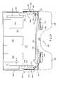
- FIG. 24is a bottom plan view of the workstation shown in FIG. 22 .
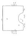
- FIG. 25is a top plan view of the workstation shown in FIG. 22 .
- FIG. 26is a front view of the workstation shown in FIG. 22 .
- FIG. 27is a rear view of the workstation shown in FIG. 22 .
- FIG. 28is a side view of the workstation shown in FIG. 22 as applied to a primary worksurface.
- FIG. 29is a cross-sectional view of the workstation taken along line 29 - 29 of FIG. 23 .
- the term “plurality,” as used herein,means two or more.
- the term “longitudinal,” as used hereinmeans of or relating to length or the lengthwise direction, and in general corresponds to a direction running between a front and back, for example from a front of a worksurface to a back thereof.
- the term “lateral,” as used herein,means situated on, directed toward or running from side to side.
- the term “worksurface” as used hereinmeans any surface capable of supporting an object, for example, a keyboard, mouse, document holder, papers etc., and includes for example and without limitation monitor supports, desk tops and/or keyboard trays/supports, and/or combinations thereof.
- Coupledmeans connected to or engaged with, whether directly or indirectly, for example with an intervening member or alternatively as integrally formed, and do not require the engagement to be fixed or permanent, although it may be fixed or permanent, and includes both mechanical and electrical connection.
- pivotrefers to the turning movement of one member or portion thereof relative to another member or portion, whether about an actual or virtual axis, whether fixed or move able, and includes bending of a unitary member such that a portion of the unitary member is “pivoted” relative to another portion about the bend.
- first and second positionsmay variously correspond to a retracted, intermediate and extended position, but also correspond to various positions therebetween, with there simply being some movement or change in position between the first and second positions.
- the primary worksurfaceis typically configured as a top of a desk, table or other type of worksurface.
- the primary worksurface 2may be freestanding, meaning it is supported on a support surface, such as a floor, by a base, for example a frame, one or more legs, pedestals, etc., or combinations thereof.
- Other primary worksurfacesmay be mounted to and extend from a vertical wall or wall panel, for example and without limitation by mounting to one or more of a wall panel frame, tile, connector or other wall panel component.
- the primary worksurfacehas an upper surface 4 oriented within a substantially horizontal plane, although it should be understood that the primary worksurface can be oriented at other suitable angles, or may be angularly, horizontally, and/or vertically adjustable.
- the workstationincludes a monitor support 10 coupled to an auxiliary worksurface 12 .
- the monitor supportis any structure capable of supporting a monitor 6 , defined as any viewing medium, such as a hard or soft screen, computer monitor, laptop computer, television or other type of know mediums, as shown for example in FIG. 4 , by directly supporting such a monitor on a support surface 4 (without any latch or lock mechanism), or by being connected to the monitor through a monitor interface, such as an articulated monitor support arm, stand, etc.
- the monitor supportcan have any plan view shape, shown for example in FIGS. 12 and 14 as a lobe-shaped base shaped to support a V-shaped monitor base.
- the monitor support 10is configured as a substantially flat worksurface member having a front 14 , rear 16 and opposite sides 24 .
- the total depth of the monitor support 10 and auxiliary worksurface 12is less than 24 inches, or less than 36 inches in another embodiment.
- the monitor supportis 121 ⁇ 2 inches deep, while the auxiliary worksurface is 101 ⁇ 2 inches deep (but may include an additional armrest or mousepad support having a depth of 71 ⁇ 2 inches), for a total depth of 301 ⁇ 2 inches.
- the width of the systemis equal to or less than about 40 inches, such that it fits on a standard 42 inch wide primary worksurface.
- the rear 16is configured in one embodiment with a vertical wall, or backsplash 28 , while in other embodiments a backsplash is omitted.
- the backsplashincludes a grommet 26 , having a plurality of resilient wire management receptacles.
- the backsplashalso can be configured to hold or connect to lighting, storage, audio speakers, articulated monitor support arms, etc.
- the monitor supportcan be configured to secure or connect to articulated, or static, monitor supports in any number of ways suitable for a particular monitor configuration.
- the monitor displayis integrally formed as part of the monitor support.
- the front 14 of the monitor supportis connected to a hinge 30 , configured in one embodiment as a piano hinge running substantially the entire width of the monitor support 20 in the lateral direction from side to side 24 .
- the hingealso can be configured as a plurality of separate, discrete hinges spaced along the length of the front, or as one or more living hinges formed in part from the monitor support itself.
- the monitor support 10 and auxiliary worksurface 12are made of metal, such as aluminum or steel, although one or both can be made of wood, plastic, composites, or combinations of such materials.
- the monitor support, as well as the auxiliary worksurfacecan include a core, such as particle board, with an overmolded cover material, such as urethane.
- the monitor support 10is configured with opposite side walls 32 that define a downwardly opening recess 34 beneath the upper worksurface.
- the auxiliary worksurface 12 as shown in FIGS. 1-7is configured with a substantially flat or planar support surface and has a front 36 , rear 38 and opposite sides 40 .
- the rear 38 of the auxiliary worksurfaceis connected to the hinge 30 , such that the auxiliary worksurface 12 is pivotally coupled to the monitor support 10 about a substantially horizontal axis 42 .
- the auxiliary worksurface 12also is configured with opposite side walls 44 that define a downwardly opening recess 46 beneath the worksurface.
- the side wallshave a concave bottom edge 20 .
- the bottom edge 20can be curved, or can be configured as a cut-out with straight edges, such as an upside down U-shape, as shown in FIG. 14 .
- the side wallscan be omitted altogether, but with the understanding that the auxiliary worksurface is spaced above the primary worksurface, such that a space or recess, oriented beneath or downwardly from the auxiliary worksurface, is formed.
- an upper surface 8 defined by the auxiliary worksurfaceis spaced no more than one (1) inch from the primary worksurface 2 when positioned thereover in a substantially parallel relationship, although it should be understood that it could be spaced a greater distance. In this way, the workstation does not appear to elevate the worksurface 12 too far above the primary worksurface 2 .
- An armrest 48may be coupled to the front of the auxiliary worksurface and form part thereof.
- the armrestmay be right or left handed, having a cutout 50 or recess positioned in the right or left hand side of the armrest, or the recess can be positioned in the middle of the armrest, with the recess providing space for the torso or body of the user.
- the front of the armrestmay be configured in any linear, curvilinear or other shape to accommodate various users.
- the armrestmay be made of any know resilient or padded materials, including a flex edge.
- the armrestmay be covered with leather.
- the armrestmay be fixedly or releasably connected to the auxiliary worksurface.
- the monitor support 10 and auxiliary worksurface 12are moveably supported by a base 150 .
- the baseincludes a plurality of tracks 52 moveably engaging guide members 54 positioned on the monitor support and auxiliary worksurface.
- the trackseach include a first and second portion 56 , 58 , otherwise referred to as first and second tracks.
- the first portionhas a substantially horizontal trajectory or path, while the second portion has a downwardly sloping trajectory relative to a horizontal plane, or other plane parallel to and defined by the primary worksurface.
- the front of the tracks 52include downwardly extending stop or clamp members 60 , which engage a front edge 62 of the primary worksurface 2 .
- a pair of adjustable rear clamp members 18extend rearwardly from the base.
- the rear clamp membersinclude an adjustment shaft 64 that can be releasably extended relative to a corresponding track 52 , with which it is slideably engaged.
- a rear stop or clamp member 66extends downwardly and is shaped to engage a rear edge 68 of the primary worksurface. In operation, the front stop member 60 is engaged with the front edge 62 of the primary worksurface and the rear stop member 66 is then brought forward into a firm, clamping engagement with the rear edge 68 such that the workstation is releasably, fixedly secured or mounted to the primary worksuface 2 .
- a lever or other release component 70is accessible and can be actuated so as to permit the extension of the adjustment shafts. When released, a clamp or cam device engages the shaft to prevent further displacement. It should be understood that any type of conventional lock device, whether having infinite, frictional adjustment, or discrete detents, can be used to secure the extension member.
- One or both of the front and rear clamp members 60 , 66can be configured with a lip that is positioned and shaped to engage a bottom of the primary worksurface so as to prevent vertical movement of the workstation relative to the primary worksurface.
- the clamping forceproduces sufficient friction to prevent such vertical movement and the lip portions can be omitted.
- the rear and/or front clampsare configured with an upper clamp surface 72 and a lower clamping member 74 .
- An adjustment mechanism 76such as a lead screw having a grippable member, is connected between the upper and lower clamp members so that they can be moved toward and away from each other to accommodate and be clamped to primary worksurfaces having different thicknesses.
- a quick release mechanism 70is provided to allow clamp bar 64 to be extended or retracted to accommodate different length primary worksurfaces.
- the base 150includes a pair of spaced apart slide support bars 152 , made for example of aluminum.
- a slide 154including in one embodiment a ball-bearing slide interface, is positioned on a rear portion of each support bar, which defines a rear track and guide.
- a second molded track 156is secured to a forward portion of the support bar, with the molded track having a downwardly sloping trajectory.
- One or more suction cups, or worksurface interface members 80are secured to the bottom of the support bars 152 and are adapted to engage the top of the primary worksurface 2 . The suction cups prevent movement of the workstation relative to the primary worksurface in response, for example, to a shear load in any direction.
- interface membersinclude without limitation felt components, padding, non-slip materials, etc.
- the bottom of the basecan directly interface with the primary worksurface and define the interface member.
- the worksurface interface membersdefine, in the aggregate, a planar bottom mounting surface, which is copalanar and/or parallel with the upper surface of the primary worksurface.
- the first and second tracks 152 , 156 and first and second guides 154 , 160are positioned entirely above the planar bottom mounting surface.
- the monitor support 10is fixedly secured to a top portion of the slide interface, or guide member 154 .
- the auxiliary worksurface 12has a pair of guide members 160 fixedly secured to a bottom thereof adjacent each front track member 156 .
- the guide membersare spaced apart and engage opposite sides of the track member 156 so as to move ably mount the auxiliary worksurface 12 to the base 150 .
- a base 250includes a single rear track 252 having a support bar 254 and a slide 256 secured to a top thereof.
- a pair of laterally extending supports 258are mounted to a front of the bar.
- a pair of front tracks 260are mounted to the supports on opposite sides of the support bar.
- the front tracksinclude a stop or clamp portion 262 and have a downwardly sloping trajectory.
- an adjustment mechanismshown as a lead screw with a grippable actuator, is situated adjacent the front edge of the desk and can be adjusted to secure the workstation.
- a pair of tracks 270can be positioned on opposite sides of the centrally located support bar to further support the monitor support.
- one or more wheels 290are mounted to the monitor support and engage the upper surface of the primary worksurface.
- the guide memberincludes a base portion 276 mounted to a bottom surface of the auxiliary worksurface, for example with mechanical fasteners, adhesive, or like fasteners, or combinations thereof.
- the guide memberscan also be integrally formed with the auxiliary worksurface.
- the guide membersinclude a guide portion 168 having a front and rear tapered contour 272 , with a central rib 274 , with the guide portion 168 received in and slideably engaging a groove 270 formed in the track member 260 .
- the rib 274acts as a pivot pin, with the tapered contour allowing the guide to pivot relative to the track as it is moved relative thereto.
- a workstation 301includes a base 300 having a pair of clamp members 302 joined with a laterally extending cross-brace 304 .
- Each clamp member 302defines a recess 306 with a support 308 shaped to receive a leading, front edge of a primary worksurface 2 .
- a pair of clamping members 310is rotatably supported on a pair of threaded actuators 312 , which threadably engage and extend through a bottom lug 314 of the clamp members 302 .
- a grippable member 316configured as a knob, can be grasped and rotated so as to clamp the primary worksurface 2 between the clamping member 310 and the support 308 .
- the cross-brace 304has opposite end portions 320 connected to the clamp members 302 and a raised intermediate portion 318 having an axis 322 vertically offset above an axis 324 of the end portions 320 adjacent an underside of a worksurface 330 so as to provide additional clearance for the legs of a user.
- the base support 308extends rearwardly from each of the clamping members 302 .
- a side 328 of the supportdefines an elongated guide member, configured as a rail, as shown in FIG. 29 .
- the sidemay alternatively be configured as a track, for example as an elongated groove or slot.
- the base 300including the clamp members 302 , cross-brace 304 and supports 308 are made of metal.
- the worksurface 330preferably is configured as a one-piece, homogenous component having a front portion 332 , defining an auxiliary worksurface, and a rear portion 334 , defining a monitor support.
- the rear portion 334also provides a worksurface area.
- the front and rear portionscan be made separate, and are thereafter joined, for example by a pivot member.
- the front and rear portionsare co-planar, and further define an upper surface substantially parallel to the primary worksurface.
- the overall height of the worksurface, defined between the upper surface thereof and the upper surface of the primary worksurfaceis preferably between about 0.25 inches and about 1.50 inches, and in one embodiment is about 0.375 inches and no more than 1.00 inch.
- the front portion 332has a leading edge 336 forming a recess 338 shaped and positioned to receive a user's body, with side portions 340 providing support for the user's arms.
- the worksurface 330is preferably made of a relatively stiff, but bendable material, including for example and without limitation a semi-rigid polymer, such as polypropylene, nylon, polycarbonate, etc., or combinations thereof.
- a backsplash 342is formed along a trailing, rear edge of the worksurface. The backsplash may be configured with various features as described above. Of course, the backsplash may be omitted.
- the width of the worksurfacemay is between about 28 and 42 inches, and may be about 36 inches, and the length of the worksurface, defined between the forwardmost leading edge of the front portion and the rear edge of the rear portion, is less than about 36 inches in one embodiment, less than about 24 inches in another embodiment, and may be between about 30 to 32 inches in another embodiment.
- a pair of anti-racking rails 344are positioned and secured to an underside 346 of the worksurface, and slide along an inner side 348 of the support 308 .
- a plurality of slide members 350shown as three, are laterally spaced along and coupled to the underside 346 of the worksurface.
- the slide members 350are preferably formed as foam battens.
- the slide members 350support the worksurface 330 on, and facilitate the sliding of the worksurface, and in particular the rear portion, along the primary worksurface 2 while preventing scuffing or other damage to the top of the primary worksurface.
- the worksurface 330and in particular at least the rear portion 334 therof, further includes an elongated track 352 formed along each of the opposite sides thereof.
- the track 352is shaped to receive the guide/rail 328 of the base support 308 , such that the worksurface 330 slides along the rail 328 between various positions, including at least a retracted position, an intermediate position and an extended position as shown in FIGS. 21A-C .
- the worksurface 330preferably is infinitely adjustable, with friction between the track 352 and guide/rail 328 maintaining the worksurface in a desired position. It should be understood that other locking mechanisms, including various detents, clamps, etc., can be used to secure the worksurface in a desired position relative to the base and/or primary worksurface.
- a pair of living hinges 360are provided along opposite sides of the worksurface 330
- the living hinges 360define a transition 364 between the front and rear portions 332 , 334 of the worksurface.
- the living hinges 360may be formed by providing a plurality of slots 362 in the edge portion of the worksurface, such that it can more easily bend.
- the remainder of the edge portionis configured as a stiffening bead 369 and forms the track 352 , at least along the rear portion of the worksurface.
- a pair of link members 370are pivotally coupled to the clamp members 302 .
- Each link member 370has a first end 372 received in a recess 380 formed in the clamp member and pivotally coupled thereto along a pivot axis 382 .
- the pivot axis 382is non-vertical, and preferably forms an angle ⁇ of between about 5 and 10 degrees relative to a vertical plane 384 . In this way, a second end 374 of each link member moves downwardly as the link members 370 pivot about the pivot axes 382 .
- the second end 374 of the link memberis configured with a guide member 376 , coupled thereto for example with a universal coupling, such that the link member can pivot relative to the guide member.
- Each guide member 376engages and slides or rolls along a track 378 secured to the underside of the worksurface, and in particular the front portion 332 thereof.
- the tracks 378are positioned and elongated in a lateral direction, although they may be oriented in other directions. It should be understood that the tracks may be linear, or curvilinear, such as with an arcuate shape. It also should be understood that the track may alternatively be formed on the end of the link member, with the guide extending from the underside of the worksurface.
- the monitor support 10In operation, after the workstation is secured to the primary worksurface 2 as explained above, the monitor support 10 , or rear region of the worksurface, can be moved between a first position and a second position, preferably within a plane, defined for example by the primary worksurface.
- the auxiliary worksurface 12or the front portion of the worksurface, which is pivotally connected to the monitor support, or rear portion of the worksurface, about the horizontal axis 42 , is automatically moveable with the monitor support from a first worksurface position to a second worksurface position.
- the auxiliary worksurface 12pivots about the horizontal axis 42 as the auxiliary worksurface 10 is moved from the first worksurface position to the second worksurface position, as shown for example in FIGS. 2-6 .
- the auxiliary worksurfacepivots about the axis 42 , the downwardly facing recess 46 , and concave recess 20 formed in the side walls, beneath the auxiliary worksurface receives a front edge portion 62 of the primary worksurface, allowing the auxiliary worksurface to pivot without interfering with the primary worksurface.
- the monitor support 10is moved within a horizontal plane, or other plane parallel to and defined by the primary worksurface.
- the monitor support and auxiliary worksurfacewill travel between about 1 and 10 inches, and in one embodiment about 7 inches.
- the auxiliary worksurfacewill pivot to about a 7 degree angle relative to the original reference plane, defined by the monitor support and/or primary worksurface.
- the auxiliary worksurface, or the front portion 332 of the worksurfacebends relative to the monitor support, or rear portion 334 of the worksurface, about a horizontal axis or axes and is automatically moveable with the rear portion 334 from a first worksurface position to a second worksurface position.
- the rear portion 334with the slide members 350 , slides on top of the primary worksurface 2 as the guides 352 formed in the sides thereof are moved along the elongated guide/rail 328 of the base.
- the position of the horizontal pivot axismay vary as the worksurface bends, and may also be virtual, or constitute a plurality of pivot axes.
- the link members 370As the rear portion 334 is translated along the rail 328 , preferably within a plane, the front portion 332 is automatically pushed forwardly. Simultaneously, the link members 370 , and in particular the second ends 374 thereof, pivot and translate outwardly relative to a longitudinally extending centerline 390 of the front portion, while the first ends 372 pivot relative to the base, and in particular the clamp member 302 . Since the pivot axes 382 of the link members 370 are non-vertical, and preferably form an angle a, relative to a laterally extending vertical plane 384 , the link members 370 pull the front portion 332 downwardly, thereby bending the worksurface 330 about a horizontal pivot axis or axes. In the reverse direction, the link members 370 push the front portion 332 upwardly to a substantially planar configuration relative to the rear portion. It should be understood that a single link member can be used to impart the pivoting/bending of the worksurface.
Landscapes
- Devices For Indicating Variable Information By Combining Individual Elements (AREA)
Abstract
Description
Claims (8)
Priority Applications (1)
| Application Number | Priority Date | Filing Date | Title |
|---|---|---|---|
| US12/509,943US8371237B2 (en) | 2008-07-30 | 2009-07-27 | Computer work station with moveable monitor support |
Applications Claiming Priority (2)
| Application Number | Priority Date | Filing Date | Title |
|---|---|---|---|
| US8477808P | 2008-07-30 | 2008-07-30 | |
| US12/509,943US8371237B2 (en) | 2008-07-30 | 2009-07-27 | Computer work station with moveable monitor support |
Publications (2)
| Publication Number | Publication Date |
|---|---|
| US20100024691A1 US20100024691A1 (en) | 2010-02-04 |
| US8371237B2true US8371237B2 (en) | 2013-02-12 |
Family
ID=41607011
Family Applications (1)
| Application Number | Title | Priority Date | Filing Date |
|---|---|---|---|
| US12/509,943Active2030-10-07US8371237B2 (en) | 2008-07-30 | 2009-07-27 | Computer work station with moveable monitor support |
Country Status (1)
| Country | Link |
|---|---|
| US (1) | US8371237B2 (en) |
Cited By (11)
| Publication number | Priority date | Publication date | Assignee | Title |
|---|---|---|---|---|
| US20130112829A1 (en)* | 2009-06-10 | 2013-05-09 | Jasen A. Stengel | Multi-Position Articulated Display Support System |
| US20130126682A1 (en)* | 2011-09-09 | 2013-05-23 | Alan L. Tholkes | Computer lift |
| US9164537B2 (en) | 2013-03-15 | 2015-10-20 | Toshiba Global Commerce Solutions Holding Corporation | Display screen assembly having a selectively engageable mount assembly |
| GB2530623A (en)* | 2014-08-07 | 2016-03-30 | Gillian Eileen Perks | An adjustable tableware holder for a table |
| US9395040B1 (en) | 2014-10-07 | 2016-07-19 | Michael Shawver | Vibration cancelling platform for use with laptops or table computers used in moving vehicles |
| US9596929B2 (en)* | 2014-11-10 | 2017-03-21 | Eugenia Koulizakis | Portable work support and keyboard/mouse tray and work station and tethered chair |
| US9637063B1 (en) | 2014-10-07 | 2017-05-02 | Michael Shawver | Vibration cancelling platform for use with laptops or tablet computers used in moving vehicles |
| WO2018056721A1 (en)* | 2016-09-21 | 2018-03-29 | 조세희 | Complex sliding desk system |
| USD891838S1 (en) | 2018-10-16 | 2020-08-04 | Smith System Manufacturing Company | Table |
| US11140982B2 (en)* | 2019-12-31 | 2021-10-12 | School Specialty, Llc | Desk support with stool |
| US11627799B2 (en) | 2020-12-04 | 2023-04-18 | Keith McRobert | Slidable work surface |
Families Citing this family (12)
| Publication number | Priority date | Publication date | Assignee | Title |
|---|---|---|---|---|
| US8371237B2 (en)* | 2008-07-30 | 2013-02-12 | Herman Miller, Inc. | Computer work station with moveable monitor support |
| USD644457S1 (en) | 2010-05-03 | 2011-09-06 | Steelcase Inc. | Table |
| USD644455S1 (en) | 2010-05-03 | 2011-09-06 | Steelcase Inc. | Table |
| US8724037B1 (en) | 2010-06-04 | 2014-05-13 | Kurt William Massey | Mounting system |
| US20130150214A1 (en)* | 2011-12-13 | 2013-06-13 | Shu-Yao Wu | Device and system for work and exercise |
| CN103300601B (en)* | 2013-06-07 | 2015-10-28 | 苏州市职业大学 | A kind of multifunctional desk |
| US9936800B2 (en) | 2015-07-28 | 2018-04-10 | The Lovesac Company | Leisure seating workstation |
| KR101776155B1 (en)* | 2016-09-12 | 2017-09-07 | 한상웅 | Desk |
| US12152720B1 (en) | 2017-04-17 | 2024-11-26 | Manehu Product Alliance, Llc | Adjustable mounting systems for televisions |
| CN108095301A (en)* | 2017-12-29 | 2018-06-01 | 王德文 | Full-automatic multi-functional stores table |
| US20210307503A1 (en)* | 2018-08-14 | 2021-10-07 | Mordechai Rozentswaig | Support for manual computer devices and upper limbs |
| WO2021159112A1 (en) | 2020-02-08 | 2021-08-12 | MANEHU PRODUCT ALLIANCE, LLC, d/b/a MANTELMOUNT | Display mounting system with adjustable weight counterbalance |
Citations (100)
| Publication number | Priority date | Publication date | Assignee | Title |
|---|---|---|---|---|
| US2341537A (en)* | 1942-03-19 | 1944-02-15 | Hamilton Mfg Co | Pivotal mounting for draftsmen's drawing boards on draftsmen's drawing tables |
| US3840221A (en) | 1973-09-04 | 1974-10-08 | W Hogan | Top-within-top for x-ray table |
| US4313112A (en) | 1979-12-17 | 1982-01-26 | Foster Daniel F | Computer work station assembly and mounting apparatus therefor |
| US4365561A (en) | 1978-10-12 | 1982-12-28 | Compagnie Du Roneo | Computer terminal station for data input and output |
| US4482063A (en) | 1980-04-04 | 1984-11-13 | Joseph J. Berke | Computer terminal support and hand rest |
| US4493267A (en) | 1982-01-18 | 1985-01-15 | Jedziniak Francis J | Securable storage assembly for data processing device |
| US4511111A (en)* | 1983-02-10 | 1985-04-16 | Hunt Manufacturing Co. | Portable keyboard support |
| US4515086A (en) | 1982-04-21 | 1985-05-07 | Hamilton Sorter Company, Inc. | Adjustable word processor work station |
| US4566741A (en) | 1981-09-04 | 1986-01-28 | Asea Aktiebolag | Supervisory desk |
| US4635893A (en)* | 1985-07-15 | 1987-01-13 | Nelson Stephen M | Adjustable support for a computer system |
| US4669789A (en) | 1985-03-19 | 1987-06-02 | Pemberton Peter F | Computer user's desk |
| US4706920A (en) | 1984-02-29 | 1987-11-17 | Nhk Spring Co. Limited | Television stand having a tilt mechanism |
| US4714025A (en) | 1984-03-16 | 1987-12-22 | Wallin Per Olov T | Arrangement for a switchboard desk |
| US4717112A (en)* | 1986-11-04 | 1988-01-05 | Pirkle Fred L | Computer workstation |
| US4779922A (en) | 1986-11-25 | 1988-10-25 | Cooper Lloyd G B | Work station system |
| US4805538A (en) | 1983-06-14 | 1989-02-21 | Jg Furniture Systems, Inc. | Electric terminal table |
| US4828342A (en) | 1988-10-03 | 1989-05-09 | Alexander Stefan | Convertible computer desk |
| US4890561A (en) | 1985-02-20 | 1990-01-02 | Rubbermaid Commercial Products Inc. | Extendable keyboard support assembly |
| US4915450A (en) | 1986-11-25 | 1990-04-10 | Cooper Lloyd G B | Work station system |
| US4981085A (en) | 1989-08-07 | 1991-01-01 | Weber-Knapp Company | Table lift mechanism |
| US5036777A (en)* | 1989-01-06 | 1991-08-06 | Glenn Barton | Portable folding ironing board |
| US5044284A (en) | 1990-03-01 | 1991-09-03 | Milton Gross | Computer workstation |
| DE4009536A1 (en) | 1990-03-24 | 1991-09-26 | Friedrich Martin | Computer work station with adjustable VDU tilt angle - has table with hinge and vertically movable rear support enabling viewing at right angles |
| DE4200965A1 (en) | 1991-01-22 | 1992-07-23 | Rainer Schmidt | Work-station with stable work table positioning - has carrier plate which can be raised and lowered by belt drive and with outer region supports |
| US5172641A (en) | 1990-10-26 | 1992-12-22 | Wasa Massivholzmoebel Gmbh | Table with movable working surface |
| US5183230A (en) | 1990-12-12 | 1993-02-02 | Fox Bay Industries, Inc. | Computer keyboard support with padded wrist support |
| US5199773A (en) | 1990-12-20 | 1993-04-06 | Engineered Data Products, Inc. | Desk type work station |
| US5240210A (en)* | 1992-06-04 | 1993-08-31 | Honto Jr Bill | Typing workstation armrest |
| US5263668A (en) | 1991-10-15 | 1993-11-23 | Ast Research, Inc. | Computer pedestal |
| US5287815A (en) | 1992-05-07 | 1994-02-22 | Milton Gross | Computer workstation |
| EP0592181A2 (en) | 1992-10-05 | 1994-04-13 | Baker Manufacturing Co., Inc | Computer work station |
| US5322026A (en) | 1992-12-21 | 1994-06-21 | Bay Il H | Waste combustion chamber with tertiary burning zone |
| US5339750A (en) | 1992-03-27 | 1994-08-23 | Hamilton Industries | Adjustable work table |
| US5398622A (en) | 1991-10-10 | 1995-03-21 | Steelcase Inc. | Adjustable dual worksurface support |
| US5408940A (en) | 1992-06-25 | 1995-04-25 | Winchell; Paul W. | Adjustable height work surface wtih rack and pinion arrangements |
| US5419525A (en) | 1993-12-13 | 1995-05-30 | Carl Hilton Corporation | Computer stand |
| US5424912A (en) | 1993-08-27 | 1995-06-13 | Mikan; Peter J. | Rack-mounted computer accessory including pull-out shelf |
| US5437235A (en) | 1993-06-10 | 1995-08-01 | Symbiote, Inc. | Computer work station |
| US5443017A (en) | 1992-03-27 | 1995-08-22 | Mayline Company, Inc. | Adjustable work table and modular system for the assembly thereof |
| US5450800A (en) | 1994-03-15 | 1995-09-19 | Leonard; Joseph W. | Ergonomically adjustable computer workstation |
| US5490466A (en) | 1994-03-15 | 1996-02-13 | Howe Furniture Corporation | Adjustable keyboard support |
| US5522323A (en) | 1993-08-24 | 1996-06-04 | Richard; Paul E. | Ergonimic computer workstation and method of using |
| US5623881A (en) | 1996-02-23 | 1997-04-29 | Huang; Feng-Chanmr | Computer desk |
| US5671091A (en) | 1994-04-15 | 1997-09-23 | The Walt Disney Company | Virtual easel |
| US5712761A (en) | 1996-09-23 | 1998-01-27 | International Business Machines, Corporation | Computer system having cooperating spring, gear tracks and geared dampers for allowing a drive housing to move between open and closed positions |
| US5765910A (en) | 1993-08-05 | 1998-06-16 | Larkin; Stephen F. | Programmed motion work station |
| US5845586A (en) | 1997-08-28 | 1998-12-08 | Balt, Inc. | Ergonomic workstation |
| US5857415A (en) | 1993-08-24 | 1999-01-12 | Richard; Paul E. | Ergonomic computer workstation and method of using |
| US5909934A (en) | 1998-07-24 | 1999-06-08 | Mcgraw; Jon | Computer desk |
| US5967631A (en) | 1998-10-23 | 1999-10-19 | Ko; Wen-Shan | Computer desk |
| US5992810A (en) | 1997-08-29 | 1999-11-30 | Ergotech (1993) Inc. | Adjustable keyboard support |
| US6076473A (en) | 1998-02-26 | 2000-06-20 | Conte; Stefano | Table for accommodating the components of a computer |
| US6092868A (en) | 1998-12-17 | 2000-07-25 | Wynn; Jeffrey J. | Computer work station |
| US6119605A (en) | 1999-06-09 | 2000-09-19 | Baker Manufacturing Company | Height adjustable table with counterbalance spring and load balance indicator |
| US6135032A (en) | 1999-01-22 | 2000-10-24 | Ko; Wen-Shan | Computer desk having ascendible and descendible desk tops |
| US6269753B1 (en) | 1998-10-26 | 2001-08-07 | Allison C. Roddan | Cantilevered, adjustable, portable computer desk |
| US6270157B1 (en) | 2000-04-06 | 2001-08-07 | Stanley Joseph Kapushinski | Floppy desk |
| US6296408B1 (en) | 1993-08-05 | 2001-10-02 | Stephen F. Larkin | Programmed motion work station |
| US6315358B1 (en) | 1997-07-28 | 2001-11-13 | Eran Baru | Computer work station |
| US20020020329A1 (en) | 2000-06-23 | 2002-02-21 | Kowalski Albert Shaw | Ergonomic visual display terminal and personal computer workstation apparatus |
| US6374752B1 (en) | 2000-03-13 | 2002-04-23 | Glenn E. Walser | Ergonomic computer workstation |
| US6382745B1 (en) | 2000-09-08 | 2002-05-07 | Avis V. Adkins | Laptop workstation |
| US20020056797A1 (en) | 2000-02-12 | 2002-05-16 | Solomon Gary B. | Apparatus for providing desktop mobility for desktop electronic devices |
| US6394402B2 (en) | 1999-09-01 | 2002-05-28 | Stinger Industries, Llc | Vertically adjustable mobile computer workstation |
| US6398326B1 (en) | 2001-11-09 | 2002-06-04 | Chih-Hsing Wang | Computer desk |
| US6419197B2 (en)* | 1999-01-19 | 2002-07-16 | Group Dekko Services, Llc | Keyboard support system |
| US6439657B1 (en) | 1999-02-25 | 2002-08-27 | Alan L. Tholkes | Synergistic body positioning and dynamic support system |
| US6446564B1 (en)* | 1999-12-16 | 2002-09-10 | Peter Charles Anderson | Desk with sliding top section and keyboard tray |
| US6471164B2 (en)* | 2000-06-15 | 2002-10-29 | James J. Diorio | Computer mouse and arm rest |
| US6474760B2 (en) | 2001-03-12 | 2002-11-05 | Rodney Rauls | Drawer for gaming devices |
| US6484648B1 (en) | 2001-04-12 | 2002-11-26 | Dennis L. Long | Adjustment mechanism for workstation |
| US6536356B2 (en) | 2000-06-08 | 2003-03-25 | Sauder Woodworking Co. | Computer desk |
| US6568650B2 (en) | 2001-10-31 | 2003-05-27 | Pelican Design | Laptop accessory |
| US6615429B2 (en) | 1999-07-30 | 2003-09-09 | Hill-Rom Services, Inc. | Apparatus for positioning a patient-support deck |
| US6615428B1 (en) | 2000-10-16 | 2003-09-09 | Ge Medical Systems Global Technology Company, Llc | Dual stage telescoping imaging table |
| US6691626B2 (en) | 2002-02-19 | 2004-02-17 | Steve Warner | Adjustable table |
| US6736469B2 (en) | 2001-01-11 | 2004-05-18 | Kenneth W. Long | Computer desk and workstation |
| US6745986B1 (en)* | 2003-01-08 | 2004-06-08 | Gregory David Bright | Support apparatus and method |
| US6799816B2 (en)* | 2002-11-12 | 2004-10-05 | William N. Touzani | Ergonomic bi-level workstation |
| US6802264B2 (en)* | 2003-01-13 | 2004-10-12 | Charles J. Kasak | Slide-away work top for computer stations |
| US20040256524A1 (en) | 2003-03-19 | 2004-12-23 | Beck Robert L. | Computer workstation with moveable monitor support |
| US20040262485A1 (en) | 2003-04-30 | 2004-12-30 | Universite De Sherbooke | Portable rest device for laptop computer |
| US6874431B1 (en) | 2003-09-05 | 2005-04-05 | Matthew G. Danna | Computer desk with slidably extendible desktop |
| US20050285004A1 (en) | 2004-05-06 | 2005-12-29 | Acco Brands, Inc. | Over-under desk apparatus and method |
| US20060027146A1 (en)* | 2004-08-09 | 2006-02-09 | Lee Tien C | Ergonomically adjustable table set |
| US7032523B2 (en) | 2003-04-03 | 2006-04-25 | Steelcase Development Corporation | Workstation with a moveable apparatus |
| US7047890B2 (en) | 2002-12-27 | 2006-05-23 | Jeffrey Korber | Integrated flat panel workstation system |
| US20060174807A1 (en) | 2005-01-26 | 2006-08-10 | Dral Joel R | Computer workstation with movable monitor support |
| US7127962B2 (en) | 2002-11-06 | 2006-10-31 | Mcgill University | Four-degree-of-freedom parallel manipulator for producing Schönflies motions |
| US7322653B2 (en) | 2003-06-13 | 2008-01-29 | Vlad Dragusin | Integrated videogaming and computer workstation |
| US20080041279A1 (en)* | 2006-07-06 | 2008-02-21 | Johnson Jerry D | Folding portable table |
| US20080072803A1 (en)* | 2006-09-25 | 2008-03-27 | Cbt Supply, Inc. | Convertible workstation |
| US7461822B2 (en)* | 2005-08-29 | 2008-12-09 | Gary Edwards | Observation stand accessory |
| US20100024691A1 (en)* | 2008-07-30 | 2010-02-04 | Weber Jeffrey A | Computer work station with moveable monitor support |
| US7739964B2 (en)* | 2005-11-04 | 2010-06-22 | Hatton Grant | Boat storage and container unit |
| US7798070B2 (en)* | 2004-10-05 | 2010-09-21 | Okamura Corporation | Table |
| US20110056412A1 (en)* | 2009-01-08 | 2011-03-10 | Phifer Incorporated | Devices For Providing A Workstation And Methods Of Making And Using The Same |
| US20110168062A1 (en)* | 2010-01-08 | 2011-07-14 | Dellavecchia Michael | Mechanically adjustable work station with optional retractable work support ledge |
| US8051782B2 (en)* | 2007-11-25 | 2011-11-08 | Anthro Corporation | Desk and display stand with height and depth adjustment |
| US8225723B2 (en)* | 2004-10-12 | 2012-07-24 | Okamura Corporation | Table with a panel |
Family Cites Families (1)
| Publication number | Priority date | Publication date | Assignee | Title |
|---|---|---|---|---|
| JP3522144B2 (en)* | 1999-02-25 | 2004-04-26 | 富士通株式会社 | Capacitance circuit and semiconductor integrated circuit device |
- 2009
- 2009-07-27USUS12/509,943patent/US8371237B2/enactiveActive
Patent Citations (105)
| Publication number | Priority date | Publication date | Assignee | Title |
|---|---|---|---|---|
| US2341537A (en)* | 1942-03-19 | 1944-02-15 | Hamilton Mfg Co | Pivotal mounting for draftsmen's drawing boards on draftsmen's drawing tables |
| US3840221A (en) | 1973-09-04 | 1974-10-08 | W Hogan | Top-within-top for x-ray table |
| US4365561A (en) | 1978-10-12 | 1982-12-28 | Compagnie Du Roneo | Computer terminal station for data input and output |
| US4313112A (en) | 1979-12-17 | 1982-01-26 | Foster Daniel F | Computer work station assembly and mounting apparatus therefor |
| US4482063A (en) | 1980-04-04 | 1984-11-13 | Joseph J. Berke | Computer terminal support and hand rest |
| US4566741A (en) | 1981-09-04 | 1986-01-28 | Asea Aktiebolag | Supervisory desk |
| US4493267A (en) | 1982-01-18 | 1985-01-15 | Jedziniak Francis J | Securable storage assembly for data processing device |
| US4515086A (en) | 1982-04-21 | 1985-05-07 | Hamilton Sorter Company, Inc. | Adjustable word processor work station |
| US4511111A (en)* | 1983-02-10 | 1985-04-16 | Hunt Manufacturing Co. | Portable keyboard support |
| US4805538A (en) | 1983-06-14 | 1989-02-21 | Jg Furniture Systems, Inc. | Electric terminal table |
| US4706920A (en) | 1984-02-29 | 1987-11-17 | Nhk Spring Co. Limited | Television stand having a tilt mechanism |
| US4714025A (en) | 1984-03-16 | 1987-12-22 | Wallin Per Olov T | Arrangement for a switchboard desk |
| US4890561A (en) | 1985-02-20 | 1990-01-02 | Rubbermaid Commercial Products Inc. | Extendable keyboard support assembly |
| US4669789A (en) | 1985-03-19 | 1987-06-02 | Pemberton Peter F | Computer user's desk |
| US4635893A (en)* | 1985-07-15 | 1987-01-13 | Nelson Stephen M | Adjustable support for a computer system |
| US4717112A (en)* | 1986-11-04 | 1988-01-05 | Pirkle Fred L | Computer workstation |
| US4779922A (en) | 1986-11-25 | 1988-10-25 | Cooper Lloyd G B | Work station system |
| US4880270A (en) | 1986-11-25 | 1989-11-14 | Cooper Lloyd G B | Work station system |
| US4915450A (en) | 1986-11-25 | 1990-04-10 | Cooper Lloyd G B | Work station system |
| US5056864A (en) | 1986-11-25 | 1991-10-15 | Workstation Environments | Work station system |
| US4828342A (en) | 1988-10-03 | 1989-05-09 | Alexander Stefan | Convertible computer desk |
| US5036777A (en)* | 1989-01-06 | 1991-08-06 | Glenn Barton | Portable folding ironing board |
| US4981085A (en) | 1989-08-07 | 1991-01-01 | Weber-Knapp Company | Table lift mechanism |
| US5044284A (en) | 1990-03-01 | 1991-09-03 | Milton Gross | Computer workstation |
| DE4009536A1 (en) | 1990-03-24 | 1991-09-26 | Friedrich Martin | Computer work station with adjustable VDU tilt angle - has table with hinge and vertically movable rear support enabling viewing at right angles |
| US5172641A (en) | 1990-10-26 | 1992-12-22 | Wasa Massivholzmoebel Gmbh | Table with movable working surface |
| US5183230A (en) | 1990-12-12 | 1993-02-02 | Fox Bay Industries, Inc. | Computer keyboard support with padded wrist support |
| US5199773A (en) | 1990-12-20 | 1993-04-06 | Engineered Data Products, Inc. | Desk type work station |
| DE4200965A1 (en) | 1991-01-22 | 1992-07-23 | Rainer Schmidt | Work-station with stable work table positioning - has carrier plate which can be raised and lowered by belt drive and with outer region supports |
| US5398622A (en) | 1991-10-10 | 1995-03-21 | Steelcase Inc. | Adjustable dual worksurface support |
| US5263668A (en) | 1991-10-15 | 1993-11-23 | Ast Research, Inc. | Computer pedestal |
| US5443017A (en) | 1992-03-27 | 1995-08-22 | Mayline Company, Inc. | Adjustable work table and modular system for the assembly thereof |
| US5339750A (en) | 1992-03-27 | 1994-08-23 | Hamilton Industries | Adjustable work table |
| US5287815A (en) | 1992-05-07 | 1994-02-22 | Milton Gross | Computer workstation |
| US5240210A (en)* | 1992-06-04 | 1993-08-31 | Honto Jr Bill | Typing workstation armrest |
| US5408940A (en) | 1992-06-25 | 1995-04-25 | Winchell; Paul W. | Adjustable height work surface wtih rack and pinion arrangements |
| EP0592181A2 (en) | 1992-10-05 | 1994-04-13 | Baker Manufacturing Co., Inc | Computer work station |
| US5322026A (en) | 1992-12-21 | 1994-06-21 | Bay Il H | Waste combustion chamber with tertiary burning zone |
| US5680820A (en) | 1993-06-10 | 1997-10-28 | Randolph; Travis M. | Computer work station |
| US5437235A (en) | 1993-06-10 | 1995-08-01 | Symbiote, Inc. | Computer work station |
| US5765910A (en) | 1993-08-05 | 1998-06-16 | Larkin; Stephen F. | Programmed motion work station |
| US6296408B1 (en) | 1993-08-05 | 2001-10-02 | Stephen F. Larkin | Programmed motion work station |
| US5857415A (en) | 1993-08-24 | 1999-01-12 | Richard; Paul E. | Ergonomic computer workstation and method of using |
| US5522323A (en) | 1993-08-24 | 1996-06-04 | Richard; Paul E. | Ergonimic computer workstation and method of using |
| US5424912A (en) | 1993-08-27 | 1995-06-13 | Mikan; Peter J. | Rack-mounted computer accessory including pull-out shelf |
| US5419525A (en) | 1993-12-13 | 1995-05-30 | Carl Hilton Corporation | Computer stand |
| US5490466A (en) | 1994-03-15 | 1996-02-13 | Howe Furniture Corporation | Adjustable keyboard support |
| US5450800A (en) | 1994-03-15 | 1995-09-19 | Leonard; Joseph W. | Ergonomically adjustable computer workstation |
| US5671091A (en) | 1994-04-15 | 1997-09-23 | The Walt Disney Company | Virtual easel |
| US5623881A (en) | 1996-02-23 | 1997-04-29 | Huang; Feng-Chanmr | Computer desk |
| US5712761A (en) | 1996-09-23 | 1998-01-27 | International Business Machines, Corporation | Computer system having cooperating spring, gear tracks and geared dampers for allowing a drive housing to move between open and closed positions |
| US6315358B1 (en) | 1997-07-28 | 2001-11-13 | Eran Baru | Computer work station |
| US5845586A (en) | 1997-08-28 | 1998-12-08 | Balt, Inc. | Ergonomic workstation |
| US5992810A (en) | 1997-08-29 | 1999-11-30 | Ergotech (1993) Inc. | Adjustable keyboard support |
| US6076473A (en) | 1998-02-26 | 2000-06-20 | Conte; Stefano | Table for accommodating the components of a computer |
| US5909934A (en) | 1998-07-24 | 1999-06-08 | Mcgraw; Jon | Computer desk |
| US5967631A (en) | 1998-10-23 | 1999-10-19 | Ko; Wen-Shan | Computer desk |
| US6269753B1 (en) | 1998-10-26 | 2001-08-07 | Allison C. Roddan | Cantilevered, adjustable, portable computer desk |
| US6092868A (en) | 1998-12-17 | 2000-07-25 | Wynn; Jeffrey J. | Computer work station |
| US6419197B2 (en)* | 1999-01-19 | 2002-07-16 | Group Dekko Services, Llc | Keyboard support system |
| US6135032A (en) | 1999-01-22 | 2000-10-24 | Ko; Wen-Shan | Computer desk having ascendible and descendible desk tops |
| US6439657B1 (en) | 1999-02-25 | 2002-08-27 | Alan L. Tholkes | Synergistic body positioning and dynamic support system |
| US6119605A (en) | 1999-06-09 | 2000-09-19 | Baker Manufacturing Company | Height adjustable table with counterbalance spring and load balance indicator |
| US6615429B2 (en) | 1999-07-30 | 2003-09-09 | Hill-Rom Services, Inc. | Apparatus for positioning a patient-support deck |
| US6394402B2 (en) | 1999-09-01 | 2002-05-28 | Stinger Industries, Llc | Vertically adjustable mobile computer workstation |
| US6446564B1 (en)* | 1999-12-16 | 2002-09-10 | Peter Charles Anderson | Desk with sliding top section and keyboard tray |
| US20020056797A1 (en) | 2000-02-12 | 2002-05-16 | Solomon Gary B. | Apparatus for providing desktop mobility for desktop electronic devices |
| US6374752B1 (en) | 2000-03-13 | 2002-04-23 | Glenn E. Walser | Ergonomic computer workstation |
| US6270157B1 (en) | 2000-04-06 | 2001-08-07 | Stanley Joseph Kapushinski | Floppy desk |
| US6536356B2 (en) | 2000-06-08 | 2003-03-25 | Sauder Woodworking Co. | Computer desk |
| US6471164B2 (en)* | 2000-06-15 | 2002-10-29 | James J. Diorio | Computer mouse and arm rest |
| US20020020329A1 (en) | 2000-06-23 | 2002-02-21 | Kowalski Albert Shaw | Ergonomic visual display terminal and personal computer workstation apparatus |
| US6382745B1 (en) | 2000-09-08 | 2002-05-07 | Avis V. Adkins | Laptop workstation |
| US6615428B1 (en) | 2000-10-16 | 2003-09-09 | Ge Medical Systems Global Technology Company, Llc | Dual stage telescoping imaging table |
| US6736469B2 (en) | 2001-01-11 | 2004-05-18 | Kenneth W. Long | Computer desk and workstation |
| US6474760B2 (en) | 2001-03-12 | 2002-11-05 | Rodney Rauls | Drawer for gaming devices |
| US6484648B1 (en) | 2001-04-12 | 2002-11-26 | Dennis L. Long | Adjustment mechanism for workstation |
| US6568650B2 (en) | 2001-10-31 | 2003-05-27 | Pelican Design | Laptop accessory |
| US6398326B1 (en) | 2001-11-09 | 2002-06-04 | Chih-Hsing Wang | Computer desk |
| US6691626B2 (en) | 2002-02-19 | 2004-02-17 | Steve Warner | Adjustable table |
| US7127962B2 (en) | 2002-11-06 | 2006-10-31 | Mcgill University | Four-degree-of-freedom parallel manipulator for producing Schönflies motions |
| US6799816B2 (en)* | 2002-11-12 | 2004-10-05 | William N. Touzani | Ergonomic bi-level workstation |
| US7047890B2 (en) | 2002-12-27 | 2006-05-23 | Jeffrey Korber | Integrated flat panel workstation system |
| US6745986B1 (en)* | 2003-01-08 | 2004-06-08 | Gregory David Bright | Support apparatus and method |
| US6802264B2 (en)* | 2003-01-13 | 2004-10-12 | Charles J. Kasak | Slide-away work top for computer stations |
| US20040256524A1 (en) | 2003-03-19 | 2004-12-23 | Beck Robert L. | Computer workstation with moveable monitor support |
| US7690317B2 (en)* | 2003-03-19 | 2010-04-06 | Herman Miller, Inc. | Computer workstation with moveable monitor support |
| US7032523B2 (en) | 2003-04-03 | 2006-04-25 | Steelcase Development Corporation | Workstation with a moveable apparatus |
| US20040262485A1 (en) | 2003-04-30 | 2004-12-30 | Universite De Sherbooke | Portable rest device for laptop computer |
| US7322653B2 (en) | 2003-06-13 | 2008-01-29 | Vlad Dragusin | Integrated videogaming and computer workstation |
| US6874431B1 (en) | 2003-09-05 | 2005-04-05 | Matthew G. Danna | Computer desk with slidably extendible desktop |
| US20050285004A1 (en) | 2004-05-06 | 2005-12-29 | Acco Brands, Inc. | Over-under desk apparatus and method |
| US20060027146A1 (en)* | 2004-08-09 | 2006-02-09 | Lee Tien C | Ergonomically adjustable table set |
| US7798070B2 (en)* | 2004-10-05 | 2010-09-21 | Okamura Corporation | Table |
| US8225723B2 (en)* | 2004-10-12 | 2012-07-24 | Okamura Corporation | Table with a panel |
| US7721658B2 (en)* | 2005-01-26 | 2010-05-25 | Herman Miller, Inc. | Computer workstation with movable monitor support |
| US20060174807A1 (en) | 2005-01-26 | 2006-08-10 | Dral Joel R | Computer workstation with movable monitor support |
| US7461822B2 (en)* | 2005-08-29 | 2008-12-09 | Gary Edwards | Observation stand accessory |
| US7739964B2 (en)* | 2005-11-04 | 2010-06-22 | Hatton Grant | Boat storage and container unit |
| US20080041279A1 (en)* | 2006-07-06 | 2008-02-21 | Johnson Jerry D | Folding portable table |
| US20080072803A1 (en)* | 2006-09-25 | 2008-03-27 | Cbt Supply, Inc. | Convertible workstation |
| US8051782B2 (en)* | 2007-11-25 | 2011-11-08 | Anthro Corporation | Desk and display stand with height and depth adjustment |
| US20100024691A1 (en)* | 2008-07-30 | 2010-02-04 | Weber Jeffrey A | Computer work station with moveable monitor support |
| US20110056412A1 (en)* | 2009-01-08 | 2011-03-10 | Phifer Incorporated | Devices For Providing A Workstation And Methods Of Making And Using The Same |
| US20110168062A1 (en)* | 2010-01-08 | 2011-07-14 | Dellavecchia Michael | Mechanically adjustable work station with optional retractable work support ledge |
Non-Patent Citations (12)
| Title |
|---|
| Australian Patent Application No. AU 2001100125 B9 entitled "Ergonomic device for use by a computer terminal user," published Aug. 2, 2001, for inventor Grant Richter, 21 pages. |
| Notice of Allowance and Fees Due in U.S. Appl. No. 10/797,581, filed Mar. 10, 2004, mailed Jul. 30, 2009, 6 pages. |
| Notice of Allowance and Fees Due in U.S. Appl. No. 11/339,988, filed Jan. 25, 2006, mailed Jan. 8, 2010, 11 pages. |
| Office Action in U.S. Appl. No. 11/339,988 for Computer Workstation With Moveable Monitor Support, mailing date May 28, 2009, 8 pages. |
| Office Communication (Office Action Summary and Interview Summary) in U.S. Appl. No. 10/797,581, filed Mar. 10, 2004, mailed Aug. 29, 2005, 11 pages. |
| Office Communication (Office Action Summary) in U.S. Appl. No. 10/797,581, filed Mar. 10, 2004, mailed Aug. 24, 2006, 6 pages. |
| Office Communication (Office Action Summary) in U.S. Appl. No. 10/797,581, filed Mar. 10, 2004, mailed Jan. 13, 2009, 12 pages. |
| Office Communication (Office Action Summary) in U.S. Appl. No. 10/797,581, filed Mar. 10, 2004, mailed Jun. 27, 2008, 2007, 10 pages. |
| Office Communication (Office Action Summary) in U.S. Appl. No. 10/797,581, filed Mar. 10, 2004, mailed Jun. 4, 2007, 8 pages. |
| Office Communication (Office Action Summary) in U.S. Appl. No. 10/797,581, filed Mar. 10, 2004, mailed Nov. 28, 2007, 8 pages. |
| Official Communication (Office Action Summary) in U.S. Appl. No. 10/797,581, filed Mar. 10, 2004, mailed Mar. 1, 2006, 8 pages. |
| Official Communication (Office Action Summary) in U.S. Appl. No. 11/339,988, filed Jan. 25, 2006, mailed May 28, 2009, 8 pages. |
Cited By (17)
| Publication number | Priority date | Publication date | Assignee | Title |
|---|---|---|---|---|
| US20130112829A1 (en)* | 2009-06-10 | 2013-05-09 | Jasen A. Stengel | Multi-Position Articulated Display Support System |
| US9103488B2 (en)* | 2009-06-10 | 2015-08-11 | Jasen A. Stengel | Multi-position articulated display support system |
| US20130126682A1 (en)* | 2011-09-09 | 2013-05-23 | Alan L. Tholkes | Computer lift |
| US9133974B2 (en)* | 2011-09-09 | 2015-09-15 | HealthPostures, LLP | Computer lift |
| US9164537B2 (en) | 2013-03-15 | 2015-10-20 | Toshiba Global Commerce Solutions Holding Corporation | Display screen assembly having a selectively engageable mount assembly |
| GB2530623B (en)* | 2014-08-07 | 2017-04-19 | Eileen Perks Gillian | An adjustable tableware holder for a table |
| GB2530623A (en)* | 2014-08-07 | 2016-03-30 | Gillian Eileen Perks | An adjustable tableware holder for a table |
| US9395040B1 (en) | 2014-10-07 | 2016-07-19 | Michael Shawver | Vibration cancelling platform for use with laptops or table computers used in moving vehicles |
| US9637063B1 (en) | 2014-10-07 | 2017-05-02 | Michael Shawver | Vibration cancelling platform for use with laptops or tablet computers used in moving vehicles |
| US9596929B2 (en)* | 2014-11-10 | 2017-03-21 | Eugenia Koulizakis | Portable work support and keyboard/mouse tray and work station and tethered chair |
| US20170143117A1 (en)* | 2014-11-10 | 2017-05-25 | Eugenia Koulizakis | Portable Work Support And Keyboard/Mouse Tray and Work Station and Tethered Chair |
| US10736419B2 (en)* | 2014-11-10 | 2020-08-11 | Nikki Koulizakis | Portable work support and keyboard/mouse tray and work station and tethered chair |
| WO2018056721A1 (en)* | 2016-09-21 | 2018-03-29 | 조세희 | Complex sliding desk system |
| USD891838S1 (en) | 2018-10-16 | 2020-08-04 | Smith System Manufacturing Company | Table |
| USD956459S1 (en) | 2018-10-16 | 2022-07-05 | Smith System Manufacturing Company | Table |
| US11140982B2 (en)* | 2019-12-31 | 2021-10-12 | School Specialty, Llc | Desk support with stool |
| US11627799B2 (en) | 2020-12-04 | 2023-04-18 | Keith McRobert | Slidable work surface |
Also Published As
| Publication number | Publication date |
|---|---|
| US20100024691A1 (en) | 2010-02-04 |
Similar Documents
| Publication | Publication Date | Title |
|---|---|---|
| US8371237B2 (en) | Computer work station with moveable monitor support | |
| US7721658B2 (en) | Computer workstation with movable monitor support | |
| US6749158B2 (en) | Computer keyboard and mouse support having moveable mouse extension | |
| US9156555B2 (en) | Desk assembly for positioning board-like electronic device | |
| US6357703B1 (en) | Computer mouse and arm rest | |
| US20100001563A1 (en) | Computer display viewing support | |
| EP1173702B1 (en) | Pull-out keyboard tray | |
| US6474760B2 (en) | Drawer for gaming devices | |
| US8459191B2 (en) | Laptop computer desk | |
| JPH10323236A (en) | Improved keyboard support mechanism | |
| US6736469B2 (en) | Computer desk and workstation | |
| US20210045536A1 (en) | Tablet | |
| US20110235249A1 (en) | Work surface articulation | |
| US20050140187A1 (en) | Computer mouse and keyboard support with chair attachment and lap system | |
| US20060065163A1 (en) | Desk with tilt-adjustable tops | |
| US20060065167A1 (en) | Desk with tilt-adjustable tops | |
| US7946551B1 (en) | Adjustable ergonomic keyboard, mouse, and wrist support | |
| US20090266954A1 (en) | Computer Mouse And Keyboard Support With Chair Attachment And Lap System | |
| CN103358958B (en) | Desktop device with positioning tablet electronic equipment and its seat | |
| US20020117589A1 (en) | Typing support | |
| CA2565613A1 (en) | Computer desk | |
| US6601815B2 (en) | Adjustable tray and method of using the same | |
| RU233396U1 (en) | Table | |
| KR101166791B1 (en) | Apparatus for supporting monitor | |
| CN209463539U (en) | Table and its adjustment mechanism |
Legal Events
| Date | Code | Title | Description |
|---|---|---|---|
| AS | Assignment | Owner name:HERMAN MILLER, INC., MICHIGAN Free format text:ASSIGNMENT OF ASSIGNORS INTEREST;ASSIGNOR:WEBER, JEFFREY A.;REEL/FRAME:023014/0416 Effective date:20090727 Owner name:HERMAN MILLER, INC.,MICHIGAN Free format text:ASSIGNMENT OF ASSIGNORS INTEREST;ASSIGNOR:WEBER, JEFFREY A.;REEL/FRAME:023014/0416 Effective date:20090727 | |
| STCF | Information on status: patent grant | Free format text:PATENTED CASE | |
| FPAY | Fee payment | Year of fee payment:4 | |
| MAFP | Maintenance fee payment | Free format text:PAYMENT OF MAINTENANCE FEE, 8TH YEAR, LARGE ENTITY (ORIGINAL EVENT CODE: M1552); ENTITY STATUS OF PATENT OWNER: LARGE ENTITY Year of fee payment:8 | |
| AS | Assignment | Owner name:GOLDMAN SACHS BANK USA, AS COLLATERAL AGENT, NEW YORK Free format text:SECURITY INTEREST;ASSIGNOR:HERMAN MILLER, INC.;REEL/FRAME:057452/0241 Effective date:20210719 | |
| AS | Assignment | Owner name:MILLERKNOLL, INC., MICHIGAN Free format text:CHANGE OF NAME;ASSIGNOR:HERMAN MILLER, INC.;REEL/FRAME:059360/0500 Effective date:20211019 | |
| MAFP | Maintenance fee payment | Free format text:PAYMENT OF MAINTENANCE FEE, 12TH YEAR, LARGE ENTITY (ORIGINAL EVENT CODE: M1553); ENTITY STATUS OF PATENT OWNER: LARGE ENTITY Year of fee payment:12 | |
| AS | Assignment | Owner name:WELLS FARGO BANK, NATIONAL ASSOCIATION, NORTH CAROLINA Free format text:ASSIGNMENT OF SECURITY INTEREST IN PATENT COLLATERAL;ASSIGNOR:GOLDMAN SACHS BANK USA;REEL/FRAME:072342/0380 Effective date:20250807 |