US8369082B2 - In-wall dock for a tablet computer - Google Patents
In-wall dock for a tablet computerDownload PDFInfo
- Publication number
- US8369082B2 US8369082B2US12/850,429US85042910AUS8369082B2US 8369082 B2US8369082 B2US 8369082B2US 85042910 AUS85042910 AUS 85042910AUS 8369082 B2US8369082 B2US 8369082B2
- Authority
- US
- United States
- Prior art keywords
- tablet computer
- wall
- housing
- dock
- receiving tray
- Prior art date
- Legal status (The legal status is an assumption and is not a legal conclusion. Google has not performed a legal analysis and makes no representation as to the accuracy of the status listed.)
- Active, expires
Links
Images


Classifications
- F—MECHANICAL ENGINEERING; LIGHTING; HEATING; WEAPONS; BLASTING
- F16—ENGINEERING ELEMENTS AND UNITS; GENERAL MEASURES FOR PRODUCING AND MAINTAINING EFFECTIVE FUNCTIONING OF MACHINES OR INSTALLATIONS; THERMAL INSULATION IN GENERAL
- F16M—FRAMES, CASINGS OR BEDS OF ENGINES, MACHINES OR APPARATUS, NOT SPECIFIC TO ENGINES, MACHINES OR APPARATUS PROVIDED FOR ELSEWHERE; STANDS; SUPPORTS
- F16M13/00—Other supports for positioning apparatus or articles; Means for steadying hand-held apparatus or articles
- F16M13/02—Other supports for positioning apparatus or articles; Means for steadying hand-held apparatus or articles for supporting on, or attaching to, an object, e.g. tree, gate, window-frame, cycle
- F—MECHANICAL ENGINEERING; LIGHTING; HEATING; WEAPONS; BLASTING
- F16—ENGINEERING ELEMENTS AND UNITS; GENERAL MEASURES FOR PRODUCING AND MAINTAINING EFFECTIVE FUNCTIONING OF MACHINES OR INSTALLATIONS; THERMAL INSULATION IN GENERAL
- F16M—FRAMES, CASINGS OR BEDS OF ENGINES, MACHINES OR APPARATUS, NOT SPECIFIC TO ENGINES, MACHINES OR APPARATUS PROVIDED FOR ELSEWHERE; STANDS; SUPPORTS
- F16M11/00—Stands or trestles as supports for apparatus or articles placed thereon ; Stands for scientific apparatus such as gravitational force meters
- F16M11/02—Heads
- F16M11/04—Means for attachment of apparatus; Means allowing adjustment of the apparatus relatively to the stand
- F16M11/041—Allowing quick release of the apparatus
- F—MECHANICAL ENGINEERING; LIGHTING; HEATING; WEAPONS; BLASTING
- F16—ENGINEERING ELEMENTS AND UNITS; GENERAL MEASURES FOR PRODUCING AND MAINTAINING EFFECTIVE FUNCTIONING OF MACHINES OR INSTALLATIONS; THERMAL INSULATION IN GENERAL
- F16M—FRAMES, CASINGS OR BEDS OF ENGINES, MACHINES OR APPARATUS, NOT SPECIFIC TO ENGINES, MACHINES OR APPARATUS PROVIDED FOR ELSEWHERE; STANDS; SUPPORTS
- F16M11/00—Stands or trestles as supports for apparatus or articles placed thereon ; Stands for scientific apparatus such as gravitational force meters
- F16M11/02—Heads
- F16M11/04—Means for attachment of apparatus; Means allowing adjustment of the apparatus relatively to the stand
- F16M11/06—Means for attachment of apparatus; Means allowing adjustment of the apparatus relatively to the stand allowing pivoting
- F16M11/10—Means for attachment of apparatus; Means allowing adjustment of the apparatus relatively to the stand allowing pivoting around a horizontal axis
- F—MECHANICAL ENGINEERING; LIGHTING; HEATING; WEAPONS; BLASTING
- F16—ENGINEERING ELEMENTS AND UNITS; GENERAL MEASURES FOR PRODUCING AND MAINTAINING EFFECTIVE FUNCTIONING OF MACHINES OR INSTALLATIONS; THERMAL INSULATION IN GENERAL
- F16M—FRAMES, CASINGS OR BEDS OF ENGINES, MACHINES OR APPARATUS, NOT SPECIFIC TO ENGINES, MACHINES OR APPARATUS PROVIDED FOR ELSEWHERE; STANDS; SUPPORTS
- F16M13/00—Other supports for positioning apparatus or articles; Means for steadying hand-held apparatus or articles
- G—PHYSICS
- G06—COMPUTING OR CALCULATING; COUNTING
- G06F—ELECTRIC DIGITAL DATA PROCESSING
- G06F1/00—Details not covered by groups G06F3/00 - G06F13/00 and G06F21/00
- G06F1/16—Constructional details or arrangements
- G—PHYSICS
- G06—COMPUTING OR CALCULATING; COUNTING
- G06F—ELECTRIC DIGITAL DATA PROCESSING
- G06F1/00—Details not covered by groups G06F3/00 - G06F13/00 and G06F21/00
- G06F1/16—Constructional details or arrangements
- G06F1/1613—Constructional details or arrangements for portable computers
- G06F1/1632—External expansion units, e.g. docking stations
- F—MECHANICAL ENGINEERING; LIGHTING; HEATING; WEAPONS; BLASTING
- F16—ENGINEERING ELEMENTS AND UNITS; GENERAL MEASURES FOR PRODUCING AND MAINTAINING EFFECTIVE FUNCTIONING OF MACHINES OR INSTALLATIONS; THERMAL INSULATION IN GENERAL
- F16M—FRAMES, CASINGS OR BEDS OF ENGINES, MACHINES OR APPARATUS, NOT SPECIFIC TO ENGINES, MACHINES OR APPARATUS PROVIDED FOR ELSEWHERE; STANDS; SUPPORTS
- F16M2200/00—Details of stands or supports
- F16M2200/02—Locking means
Definitions
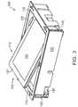
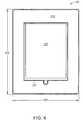
- the in-wall dock 100comprises a housing 130 having opposing pairs of exterior side walls, a front face 135 , and a back face 200 .
- the front face 135 of the housing 130is preferably arranged substantially parallel with the wall surface facing the room, and may overlap a portion of the wall, while the exterior side walls, and the back face 210 , are disposed within the wall cavity (i.e., the stud bay).
- the housing 130is sized to have a height 230 of approximately 11.2 inches, a width 240 of approximately 8.3 inches, and a depth ( FIG. 7 , 720 ) of approximately 2.5 inches, to accommodate an Ipad® tablet.
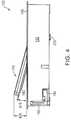
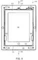
- the receiving tray 150is rotated to its second orientation, so that it is substantially parallel to the front face 135 of the housing 130 . While in the second orientation, the front face 127 of the tablet computer 110 is disposed flush, or nearly flush, to the front face 135 of the housing 130 .
- inner sidewalls ( FIG. 7 ) 170 , 175 of the housingengage opposing ends of the tablet computer 110 , and substantially prevent movement of the tablet computer 110 in directions 155 , 157 parallel to the major axis of the tablet computer 110 .
- the fastenermay have an uncommon head configuration, for example, a Robertson (square) head, an Allen (hex socket) head, a Torx or Security Torx head, a Tri-Wing head, a Spanner head, a Double hex head, a Bristol head, etc. that may discourage unwanted removal.
- the lock down mechanismmay take a different form, and, for example, may include a keyed lock set, a locking clip or clamp, or other mechanisms. While the lockdown mechanism may discourage unwanted removal, should the tablet computer 110 require removal, for example, for maintenance or replacement, the lockdown mechanism may permit such action.
Landscapes
- Engineering & Computer Science (AREA)
- General Engineering & Computer Science (AREA)
- Mechanical Engineering (AREA)
- Theoretical Computer Science (AREA)
- Human Computer Interaction (AREA)
- Physics & Mathematics (AREA)
- General Physics & Mathematics (AREA)
- Computer Hardware Design (AREA)
- Casings For Electric Apparatus (AREA)
- Media Introduction/Drainage Providing Device (AREA)
Abstract
Description
Claims (20)
Priority Applications (13)
| Application Number | Priority Date | Filing Date | Title |
|---|---|---|---|
| US12/850,429US8369082B2 (en) | 2010-08-04 | 2010-08-04 | In-wall dock for a tablet computer |
| BR112013002707-0ABR112013002707B1 (en) | 2010-08-04 | 2011-07-27 | WALL RECEIVER FOR A TABLET COMPUTER |
| CN201180048345.9ACN103119349B (en) | 2010-08-04 | 2011-07-27 | In-wall dock for tablet |
| PCT/US2011/001322WO2012018373A1 (en) | 2010-08-04 | 2011-07-27 | In-wall dock for a tablet computer |
| JP2013523147AJP5842002B2 (en) | 2010-08-04 | 2011-07-27 | Wall-mounted dock for tablet computers |
| MX2013001477AMX2013001477A (en) | 2010-08-04 | 2011-07-27 | In-wall dock for a tablet computer. |
| RU2013106239/08ARU2584488C2 (en) | 2010-08-04 | 2011-07-27 | Wall-mounted docking station for tablet computer |
| CA2807467ACA2807467C (en) | 2010-08-04 | 2011-07-27 | In-wall dock for a tablet computer |
| ES11743674.1TES2650671T3 (en) | 2010-08-04 | 2011-07-27 | Built-in tablet computer base |
| KR1020137005297AKR101877076B1 (en) | 2010-08-04 | 2011-07-27 | In-wall dock for a tablet computer |
| AU2011286449AAU2011286449B2 (en) | 2010-08-04 | 2011-07-27 | In-wall dock for a tablet computer |
| EP11743674.1AEP2601432B1 (en) | 2010-08-04 | 2011-07-27 | In-wall dock for a tablet computer |
| IL224573AIL224573A (en) | 2010-08-04 | 2013-02-04 | In-wall dock for a tablet computer |
Applications Claiming Priority (1)
| Application Number | Priority Date | Filing Date | Title |
|---|---|---|---|
| US12/850,429US8369082B2 (en) | 2010-08-04 | 2010-08-04 | In-wall dock for a tablet computer |
Publications (2)
| Publication Number | Publication Date |
|---|---|
| US20120033375A1 US20120033375A1 (en) | 2012-02-09 |
| US8369082B2true US8369082B2 (en) | 2013-02-05 |
Family
ID=44630228
Family Applications (1)
| Application Number | Title | Priority Date | Filing Date |
|---|---|---|---|
| US12/850,429Active2031-04-16US8369082B2 (en) | 2010-08-04 | 2010-08-04 | In-wall dock for a tablet computer |
Country Status (13)
| Country | Link |
|---|---|
| US (1) | US8369082B2 (en) |
| EP (1) | EP2601432B1 (en) |
| JP (1) | JP5842002B2 (en) |
| KR (1) | KR101877076B1 (en) |
| CN (1) | CN103119349B (en) |
| AU (1) | AU2011286449B2 (en) |
| BR (1) | BR112013002707B1 (en) |
| CA (1) | CA2807467C (en) |
| ES (1) | ES2650671T3 (en) |
| IL (1) | IL224573A (en) |
| MX (1) | MX2013001477A (en) |
| RU (1) | RU2584488C2 (en) |
| WO (1) | WO2012018373A1 (en) |
Cited By (37)
| Publication number | Priority date | Publication date | Assignee | Title |
|---|---|---|---|---|
| US20120170212A1 (en)* | 2011-01-05 | 2012-07-05 | Mophie, Inc. | Tablet computer stand |
| US20130058022A1 (en)* | 2011-09-03 | 2013-03-07 | Edward Alan Knutson | Dock For Portable Electronic Devices |
| US20130159583A1 (en)* | 2004-09-09 | 2013-06-20 | Dana Innovations | Computer Wall Docking Station |
| US20140118930A1 (en)* | 2012-10-31 | 2014-05-01 | Invue Security Products Inc. | Display stand for a tablet computer |
| US20140235963A1 (en)* | 2013-02-15 | 2014-08-21 | Welch Allyn, Inc. | Remote Health Care System |
| DE202013103936U1 (en) | 2013-08-30 | 2014-12-01 | viveroo GmbH | Holding device for a mobile communication device |
| USD721377S1 (en) | 2013-08-30 | 2015-01-20 | viveroo GmbH | Support for mobile electronic devices |
| USD721649S1 (en) | 2014-01-02 | 2015-01-27 | Mophie, Inc. | Electrical charger and docking station |
| USD722056S1 (en) | 2013-01-08 | 2015-02-03 | Mophie, Inc. | Desktop mobile device dock |
| WO2015027993A1 (en) | 2013-08-30 | 2015-03-05 | viveroo GmbH | Retaining device for a mobile communication device |
| USD726175S1 (en) | 2013-01-08 | 2015-04-07 | Mophie, Inc. | Mobile device vehicle mount |
| US20150237750A1 (en)* | 2011-09-21 | 2015-08-20 | The Joy Factory, Inc. | Detachable mounting systems for electronic devices |
| US9310020B1 (en) | 2013-09-17 | 2016-04-12 | Douglas B. Bernards | Mobile device mounting system and method |
| USD776119S1 (en) | 2013-12-16 | 2017-01-10 | Amphenol Thermometrics, Inc. | Portable electronic device, docking station, and/or base electronic device |
| US9577694B1 (en) | 2015-01-06 | 2017-02-21 | Jeffrey M. Albee | Support structure to enable use of tablet computer by persons with limited manual dexterity |
| WO2017088035A1 (en)* | 2015-11-23 | 2017-06-01 | Bonder Claudio | Structural arrangement of a wall holder for portable electronic appliances |
| USD804451S1 (en)* | 2015-06-02 | 2017-12-05 | Gecko Alliance Group Inc. | Media player docking station for bathing unit or watercraft |
| US10225914B2 (en)* | 2014-03-06 | 2019-03-05 | William J. Rintz | Portable programmable display and control module |
| USD842818S1 (en) | 2015-06-23 | 2019-03-12 | Gecko Alliance Group Inc. | Top-side control panel for bathing unit |
| US10353499B2 (en) | 2015-07-14 | 2019-07-16 | Gecko Alliance Group Inc. | Topside control panel for bathing unit system |
| USD859393S1 (en) | 2018-01-05 | 2019-09-10 | Mophie Inc. | Electronic device mount |
| USD873272S1 (en) | 2018-06-22 | 2020-01-21 | Mophie Inc. | Mount for electronic device |
| USD873260S1 (en) | 2018-06-22 | 2020-01-21 | Mophie Inc. | Mount for electronic device |
| USD878804S1 (en) | 2018-10-02 | 2020-03-24 | Amitabh Khardori | Shelf |
| US10615618B1 (en) | 2016-05-18 | 2020-04-07 | George Hires | Dock for securing an electronic device |
| USD892123S1 (en) | 2018-07-16 | 2020-08-04 | ACCO Brands Corporation | Dock for a portable electronic device |
| US10747265B2 (en) | 2017-07-10 | 2020-08-18 | Innov8 Cabin Solutions, LLC | Wall mount system for personal electronic devices |
| RU199218U1 (en)* | 2020-04-27 | 2020-08-21 | Общество с ограниченной ответственностью «ДЕЛАЙТ 2000» | DEVICE FOR AUDIO DATA PLAYBACK, INFORMATION DISPLAY AND VIDEO CONTENT |
| US10907383B2 (en) | 2017-03-01 | 2021-02-02 | ACCO Brands Corporation | Dock for a portable electronic device |
| US10917986B2 (en) | 2018-03-08 | 2021-02-09 | ACCO Brands Corporation | Dock for a portable electronic device |
| US11008103B1 (en) | 2019-10-28 | 2021-05-18 | B/E Aerospace, Inc. | Aircraft cabin apparatus including personal electronic device holder |
| US11014509B2 (en) | 2019-02-13 | 2021-05-25 | Mophie Inc. | Mount for holding a mobile electronic device |
| US11029548B2 (en)* | 2019-09-13 | 2021-06-08 | Panasonic Avionics Corporation | In-flight entertainment systems and monitor assemblies for in-flight entertainment systems |
| US11099605B2 (en)* | 2019-04-03 | 2021-08-24 | Dell Products, L.P. | Charger stand for multi-form factor information handling systems (IHSs) |
| US11305876B2 (en) | 2018-07-10 | 2022-04-19 | Rockwell Collins, Inc. | Aircraft cabin apparatus including personal electronic device holder |
| US20220396219A1 (en)* | 2021-06-11 | 2022-12-15 | Yazaki Corporation | Unauthorized connection detecting device |
| US12086334B2 (en) | 2021-11-01 | 2024-09-10 | Gecko Alliance Group Inc. | Topside control panel and topside control panel system for a bathing unit system and method of operating same |
Families Citing this family (49)
| Publication number | Priority date | Publication date | Assignee | Title |
|---|---|---|---|---|
| US9405395B2 (en)* | 2010-08-04 | 2016-08-02 | Crestron Electronics, Inc. | Wall-mounted control system for a portable touch screen device |
| US20120069496A1 (en)* | 2010-09-21 | 2012-03-22 | Sony Corporation | System and method for device stabilization |
| GB201021187D0 (en)* | 2010-12-14 | 2011-01-26 | Audiovox Incaar Systems Gmbh | Vehicle entertainment system |
| US8659889B2 (en)* | 2011-05-20 | 2014-02-25 | Apple Inc. | Docking station for providing digital signage |
| US20120307422A1 (en)* | 2011-05-30 | 2012-12-06 | Leao Wang | Automatic docking base for connecting external connectors of digital device |
| CN102856755B (en)* | 2011-06-28 | 2016-04-20 | 富泰华工业(深圳)有限公司 | Base |
| US8911246B2 (en)* | 2012-02-23 | 2014-12-16 | Jeffrey D. Carnevali | Universal adaptor mount for a docking station |
| US8926349B2 (en)* | 2012-02-23 | 2015-01-06 | Jeffrey D. Carnevali | Universal adaptor mount for a docking station |
| US20130272041A1 (en)* | 2012-04-13 | 2013-10-17 | Aeon Labs | Electrical device with low voltage output and low voltage touch panel |
| EP2856289A4 (en)* | 2012-05-25 | 2016-01-06 | Immerz Inc | Haptic interface for portable electronic device |
| CN104782239A (en)* | 2012-07-12 | 2015-07-15 | Dci营销公司 | Device security system |
| US8891230B1 (en) | 2012-07-17 | 2014-11-18 | Brett E. Jorgensen | Tablet computer protector and covering assembly |
| US20140075075A1 (en)* | 2012-09-11 | 2014-03-13 | Google Inc. | Context-Dependent Home Automation Controller and Docking Station |
| US9760116B2 (en) | 2012-12-05 | 2017-09-12 | Mobile Tech, Inc. | Docking station for tablet device |
| CA2896392C (en)* | 2013-01-03 | 2017-05-16 | Claris Healthcare Inc. | Computer apparatus for use by senior citizens |
| KR102036887B1 (en)* | 2013-01-07 | 2019-11-26 | 삼성전자주식회사 | Support frame and displyay apparatus and television having the same |
| US9538117B2 (en)* | 2013-01-07 | 2017-01-03 | Samsung Electronics Co., Ltd. | Support frame and display device including the same |
| US9689527B2 (en)* | 2013-03-15 | 2017-06-27 | Lee Christopher Franklin | Mounting apparatus |
| ITTO20130268A1 (en)* | 2013-04-03 | 2014-10-04 | Martino Rosario De | MUSICAL INSTRUMENT PANELS WITH MULTIMEDIA AND INTERACTIVE FUNCTIONS, SOUND AND VISUAL EFFECTS |
| KR20140141400A (en) | 2013-05-29 | 2014-12-10 | 삼성전자주식회사 | Display apparatus |
| WO2015050590A2 (en) | 2013-06-11 | 2015-04-09 | Invue Security Products Inc. | Anti-theft device for portable electronic device |
| US11085184B2 (en) | 2014-02-20 | 2021-08-10 | Dirtt Environmental Solutions Ltd. | Interface for mounting interchangable components |
| KR101509041B1 (en)* | 2014-03-24 | 2015-04-08 | 금오공과대학교 산학협력단 | docking audio for mobile audio apparatus |
| JP2017534305A (en)* | 2014-07-08 | 2017-11-24 | リー クリストファー フランクリンLee Christopher FRANKLIN | Mounting device |
| KR102230076B1 (en)* | 2014-09-01 | 2021-03-19 | 삼성전자 주식회사 | Head-mounted display apparatus |
| US9727085B2 (en)* | 2015-02-04 | 2017-08-08 | Inducomp Corporation | Tablet computer system |
| WO2016149362A1 (en) | 2015-03-16 | 2016-09-22 | Dirtt Environmental Solutions, Inc. | Glass panel reconfigurable wall panels |
| FR3034536A1 (en)* | 2015-04-03 | 2016-10-07 | Intectra | METHOD FOR LOCKING A TOUCH DIGITAL DEVICE ON A BASE |
| US9871548B2 (en)* | 2015-04-15 | 2018-01-16 | Hank Technology Llc | Secure electronic communication devices |
| WO2017059052A1 (en) | 2015-09-30 | 2017-04-06 | Invue Security Products Inc. | Gang charger, shroud, and dock for portable electronic devices |
| US10517056B2 (en) | 2015-12-03 | 2019-12-24 | Mobile Tech, Inc. | Electronically connected environment |
| US11109335B2 (en) | 2015-12-03 | 2021-08-31 | Mobile Tech, Inc. | Wirelessly connected hybrid environment of different types of wireless nodes |
| US10251144B2 (en) | 2015-12-03 | 2019-04-02 | Mobile Tech, Inc. | Location tracking of products and product display assemblies in a wirelessly connected environment |
| US10728868B2 (en) | 2015-12-03 | 2020-07-28 | Mobile Tech, Inc. | Remote monitoring and control over wireless nodes in a wirelessly connected environment |
| US10402142B2 (en)* | 2016-01-25 | 2019-09-03 | Pathway Innovations And Technologies, Inc. | Interactive flat panel display with integrated document camera |
| US9877096B2 (en) | 2016-01-27 | 2018-01-23 | Thomas Henry Harms | Portable speaker mount |
| EP3322863A4 (en) | 2016-06-10 | 2019-05-01 | DIRTT Environmental Solutions, Ltd. | GLASS SUBSTRATES WITH TOUCH SCREEN TECHNOLOGY |
| CA2992856A1 (en)* | 2016-06-10 | 2017-12-14 | Dirtt Environmental Solutions Inc. | Wall system with electronic device mounting assembly |
| CA3030282A1 (en) | 2016-07-08 | 2018-01-11 | Dirtt Environmental Solutions, Inc. | Low-voltage smart glass |
| US10101770B2 (en) | 2016-07-29 | 2018-10-16 | Mobile Tech, Inc. | Docking system for portable computing device in an enclosure |
| US10779098B2 (en)* | 2018-07-10 | 2020-09-15 | Masimo Corporation | Patient monitor alarm speaker analyzer |
| FR3084769B1 (en)* | 2018-08-06 | 2021-05-07 | Ingenico Group | RECEPTION STATION FOR ELECTRONIC PAYMENT TERMINAL, CORRESPONDING TERMINAL AND ELECTRONIC PAYMENT SYSTEM |
| US11465567B2 (en) | 2018-10-24 | 2022-10-11 | Fca Us Llc | Vehicle rear seat secured storage systems |
| US12035422B2 (en) | 2018-10-25 | 2024-07-09 | Mobile Tech, Inc. | Proxy nodes for expanding the functionality of nodes in a wirelessly connected environment |
| US10593443B1 (en) | 2019-01-24 | 2020-03-17 | Mobile Tech, Inc. | Motion sensing cable for intelligent charging of devices |
| IT201900004994A1 (en)* | 2019-04-03 | 2020-10-03 | Hics S R L | HOME AUTOMATION CONTROL DEVICE WITH REMOVABLE CONTROL PANEL |
| WO2021091528A1 (en)* | 2019-11-05 | 2021-05-14 | Hewlett-Packard Development Company L.P. | Back cover coupling for electronic devices |
| US20220341537A1 (en)* | 2019-11-06 | 2022-10-27 | Hewlett-Packard Development Company, L.P. | Computing device stands and display mount interface spacers |
| US12428878B1 (en) | 2024-05-31 | 2025-09-30 | Invue Security Products Inc. | Security device |
Citations (23)
| Publication number | Priority date | Publication date | Assignee | Title |
|---|---|---|---|---|
| US5267775A (en)* | 1991-10-03 | 1993-12-07 | B/E Avionics, Inc. | System for mounting a monitor |
| US6130727A (en)* | 1997-12-18 | 2000-10-10 | Harness System Technologies Research, Ltd. | On-vehicle unit |
| US6504710B2 (en)* | 1998-11-27 | 2003-01-07 | Xplore Technologies Corp. | Method of interconnecting of a hand-held auxiliary unit, a portable computer and a peripheral device |
| US20030137584A1 (en)* | 2001-10-29 | 2003-07-24 | Gene Norvell | Detachable vehicle monitor |
| US6739654B1 (en)* | 2003-04-24 | 2004-05-25 | Hexa-Chain Co., Ltd. | Headrest-mount display mounting structure |
| WO2005047786A1 (en) | 2003-11-14 | 2005-05-26 | Lg Electronics Inc. | Refrigerator |
| DE10352906A1 (en) | 2003-11-11 | 2005-06-30 | Oty Gmbh | Flush wall box for holding a large flat screen monitor holds the monitor at a distance from the walls of the flush wall box by means of base and rear-wall mountings |
| US20050200697A1 (en)* | 2003-05-15 | 2005-09-15 | Audiovox Corporation | Headrest mountable video system |
| US20050204596A1 (en)* | 2004-03-18 | 2005-09-22 | Peng Juen T | Portable seat back display |
| US20060052097A1 (en) | 2004-09-09 | 2006-03-09 | Scott Struthers | I-Port controller |
| US20060109388A1 (en)* | 1998-12-28 | 2006-05-25 | Johnson Controls Technology Company | Wireless signal system for a video display unit |
| US20060148575A1 (en)* | 2003-11-07 | 2006-07-06 | Vitito Christopher J | Automobile entertainment system |
| US20060285287A1 (en)* | 2005-06-17 | 2006-12-21 | Hsuan-Chen Chen | Protecting apparatus for storage device |
| US20070047198A1 (en)* | 2005-08-24 | 2007-03-01 | Apple Computer, Inc. A California Corporation | Docking station for hand held electronic devices |
| US20070052618A1 (en)* | 2003-05-15 | 2007-03-08 | Samsung Electronics Co., Ltd. | Entertainment system mountable in a vehicle seat |
| US20070070192A1 (en)* | 2003-05-15 | 2007-03-29 | Shalam David M | Entertainment system mountable in a vehicle seat and methods for mounting and displaying same |
| US7201354B1 (en)* | 2003-12-24 | 2007-04-10 | Ktv Usa, Inc. | Video monitor mounting system |
| US20070108788A1 (en)* | 2003-05-15 | 2007-05-17 | Audiovox Corporation | In-vehicle docking station for a portable media player |
| US20070247800A1 (en)* | 2004-03-08 | 2007-10-25 | Originatic Llc | Assembly having a main unit and a mounting unit |
| US7408596B2 (en)* | 2004-02-20 | 2008-08-05 | Actuant Corporation | Articulating mount for an in-vehicle display |
| US20100014228A1 (en)* | 2005-10-31 | 2010-01-21 | David Quijano | Electronic Device Quick Connect System |
| US20100138581A1 (en)* | 2008-12-02 | 2010-06-03 | Randall Bird | Universal Docking System |
| AT11510U1 (en) | 2010-03-04 | 2010-11-15 | Iroom Gmbh | WALL MOUNTING DOCKING STATION FOR THE APPLE IPAD |
Family Cites Families (9)
| Publication number | Priority date | Publication date | Assignee | Title |
|---|---|---|---|---|
| JPH04346496A (en)* | 1991-05-24 | 1992-12-02 | Fujitsu Ten Ltd | Mounting structure of electronic equipment |
| JPH0596519U (en)* | 1992-05-29 | 1993-12-27 | 沖電気工業株式会社 | Electronic device fixed structure |
| JPH0744663A (en)* | 1993-07-28 | 1995-02-14 | Ricoh Co Ltd | Electronics |
| JPH07298378A (en)* | 1994-04-21 | 1995-11-10 | Hitachi Ltd | Wireless remote control attachment |
| RU2150736C1 (en)* | 1996-12-27 | 2000-06-10 | Зи Ай.Ди.И.Эй. Копэрейшн | Modular portable workstation |
| JP4526981B2 (en)* | 2005-03-09 | 2010-08-18 | パイオニア株式会社 | Electrical equipment fixtures |
| CN201043670Y (en)* | 2007-02-02 | 2008-04-02 | 昆盈企业股份有限公司 | Support seat structure of computer peripheral device |
| RU74721U1 (en)* | 2008-03-28 | 2008-07-10 | Общество с ограниченной ответственностью "Технические системы-сервис, качество и надежность" | INDUSTRIAL TABLET COMPUTER |
| KR20100005786U (en)* | 2008-11-28 | 2010-06-07 | 서진호 | Holding device for cars |
- 2010
- 2010-08-04USUS12/850,429patent/US8369082B2/enactiveActive
- 2011
- 2011-07-27KRKR1020137005297Apatent/KR101877076B1/enactiveActive
- 2011-07-27EPEP11743674.1Apatent/EP2601432B1/enactiveActive
- 2011-07-27WOPCT/US2011/001322patent/WO2012018373A1/enactiveApplication Filing
- 2011-07-27BRBR112013002707-0Apatent/BR112013002707B1/enactiveIP Right Grant
- 2011-07-27JPJP2013523147Apatent/JP5842002B2/enactiveActive
- 2011-07-27MXMX2013001477Apatent/MX2013001477A/enactiveIP Right Grant
- 2011-07-27ESES11743674.1Tpatent/ES2650671T3/enactiveActive
- 2011-07-27CACA2807467Apatent/CA2807467C/enactiveActive
- 2011-07-27RURU2013106239/08Apatent/RU2584488C2/enactive
- 2011-07-27CNCN201180048345.9Apatent/CN103119349B/enactiveActive
- 2011-07-27AUAU2011286449Apatent/AU2011286449B2/enactiveActive
- 2013
- 2013-02-04ILIL224573Apatent/IL224573A/enactiveIP Right Grant
Patent Citations (28)
| Publication number | Priority date | Publication date | Assignee | Title |
|---|---|---|---|---|
| US5267775A (en)* | 1991-10-03 | 1993-12-07 | B/E Avionics, Inc. | System for mounting a monitor |
| US6130727A (en)* | 1997-12-18 | 2000-10-10 | Harness System Technologies Research, Ltd. | On-vehicle unit |
| US6504710B2 (en)* | 1998-11-27 | 2003-01-07 | Xplore Technologies Corp. | Method of interconnecting of a hand-held auxiliary unit, a portable computer and a peripheral device |
| US20060109388A1 (en)* | 1998-12-28 | 2006-05-25 | Johnson Controls Technology Company | Wireless signal system for a video display unit |
| US20030137584A1 (en)* | 2001-10-29 | 2003-07-24 | Gene Norvell | Detachable vehicle monitor |
| US6739654B1 (en)* | 2003-04-24 | 2004-05-25 | Hexa-Chain Co., Ltd. | Headrest-mount display mounting structure |
| US20050200697A1 (en)* | 2003-05-15 | 2005-09-15 | Audiovox Corporation | Headrest mountable video system |
| US7954894B2 (en)* | 2003-05-15 | 2011-06-07 | Audiovox Corporation | Headrest mountable video system |
| US7791586B2 (en)* | 2003-05-15 | 2010-09-07 | Audiovox Corporation | Entertainment system mountable in a vehicle seat |
| US20070070192A1 (en)* | 2003-05-15 | 2007-03-29 | Shalam David M | Entertainment system mountable in a vehicle seat and methods for mounting and displaying same |
| US20070108788A1 (en)* | 2003-05-15 | 2007-05-17 | Audiovox Corporation | In-vehicle docking station for a portable media player |
| US20070052618A1 (en)* | 2003-05-15 | 2007-03-08 | Samsung Electronics Co., Ltd. | Entertainment system mountable in a vehicle seat |
| US20060148575A1 (en)* | 2003-11-07 | 2006-07-06 | Vitito Christopher J | Automobile entertainment system |
| DE10352906A1 (en) | 2003-11-11 | 2005-06-30 | Oty Gmbh | Flush wall box for holding a large flat screen monitor holds the monitor at a distance from the walls of the flush wall box by means of base and rear-wall mountings |
| WO2005047786A1 (en) | 2003-11-14 | 2005-05-26 | Lg Electronics Inc. | Refrigerator |
| US7201354B1 (en)* | 2003-12-24 | 2007-04-10 | Ktv Usa, Inc. | Video monitor mounting system |
| US7408596B2 (en)* | 2004-02-20 | 2008-08-05 | Actuant Corporation | Articulating mount for an in-vehicle display |
| US20070247800A1 (en)* | 2004-03-08 | 2007-10-25 | Originatic Llc | Assembly having a main unit and a mounting unit |
| US20050204596A1 (en)* | 2004-03-18 | 2005-09-22 | Peng Juen T | Portable seat back display |
| US7155214B2 (en) | 2004-09-09 | 2006-12-26 | Dana Innovations | I-port controller |
| US7493142B2 (en) | 2004-09-09 | 2009-02-17 | Dana Innovations | I-port controller |
| US20060052097A1 (en) | 2004-09-09 | 2006-03-09 | Scott Struthers | I-Port controller |
| US20060285287A1 (en)* | 2005-06-17 | 2006-12-21 | Hsuan-Chen Chen | Protecting apparatus for storage device |
| US20070047198A1 (en)* | 2005-08-24 | 2007-03-01 | Apple Computer, Inc. A California Corporation | Docking station for hand held electronic devices |
| US20100014228A1 (en)* | 2005-10-31 | 2010-01-21 | David Quijano | Electronic Device Quick Connect System |
| WO2007056425A2 (en) | 2005-11-07 | 2007-05-18 | Audiovox Corporation | Entertainment system mountable in a vehicle seat and methods for mounting and displaying same |
| US20100138581A1 (en)* | 2008-12-02 | 2010-06-03 | Randall Bird | Universal Docking System |
| AT11510U1 (en) | 2010-03-04 | 2010-11-15 | Iroom Gmbh | WALL MOUNTING DOCKING STATION FOR THE APPLE IPAD |
Non-Patent Citations (12)
| Title |
|---|
| "8'' In-wall Touchscreen PC-N8WTS Spec Sheet," Nobu, LLC, Oct. 10, 2006, pp. 1-2. |
| "8″ In-wall Touchscreen PC-N8WTS Spec Sheet," Nobu, LLC, Oct. 10, 2006, pp. 1-2. |
| "CEN-IDOCV-DSW Wall Mount Interference for Apple iPod®," Crestron Electronics, Inc., May 30, 2010, pp. 1-3. |
| "FlexDock-Le-Series Spec Sheet," Motion Computing, http://www.motioncomputing.com/choose/spec-flexdock-LE.htm, Jan. 30, 2010, pp. 1. |
| "iDock iPad® Docking Station: iDock Wall Charging Station: iPad® Storage in a High Quality Environment," iRoom Technical Specifications, retrieved on Aug. 11, 2010, pp. 1-4. |
| "IW-20 Spec Sheet," iPort, Dec. 7, 2009, pp. 1-2. |
| "IW-21 Spec Sheet," iPort, Jan. 7, 2010, pp. 1-2. |
| "IW-22 Spec Sheet," iPort, Jan. 7, 2010, pp. 1-2. |
| "N8WTS Fanless Inwall Touch Screen PC: User's Manual," vol. v1.2, Nobu, LLC, Jun. 2008, pp. 1-29. |
| "Notification of Transmittal of the International Search Report and the Written Opinion of the International Searching Authority, or the Declaration," International Filing Date: Jul. 27, 2011, International Application No. PCT/US2011/001322, Applicant: Savant Systems LLC, Date of Mailing: Nov. 7, 2011, pp. 1-12. |
| "ROSIE In-Wall Media Dock Cut Sheet," Savant Systems, LLC, May 14, 2009, pp. 1-3. |
| Knott, Jason, "iPort Ships In-Wall iPad, iPod Touch Docks," CE Pro, <http://www.cepro.com/article/iport-ships-in-wall-ipad-ipod-touch-docks/>, Jul. 8, 2010, p. 1. |
Cited By (47)
| Publication number | Priority date | Publication date | Assignee | Title |
|---|---|---|---|---|
| US20140244882A1 (en)* | 2004-09-09 | 2014-08-28 | Dana Innovations | Computer Wall Docking Station |
| US20130159583A1 (en)* | 2004-09-09 | 2013-06-20 | Dana Innovations | Computer Wall Docking Station |
| US20120170212A1 (en)* | 2011-01-05 | 2012-07-05 | Mophie, Inc. | Tablet computer stand |
| US9274556B2 (en)* | 2011-01-05 | 2016-03-01 | Mophie, Inc. | Tablet computer stand |
| US9189024B2 (en)* | 2011-09-03 | 2015-11-17 | Vieira Systems Inc. | Dock for portable electronic devices |
| US20130058022A1 (en)* | 2011-09-03 | 2013-03-07 | Edward Alan Knutson | Dock For Portable Electronic Devices |
| US20150237750A1 (en)* | 2011-09-21 | 2015-08-20 | The Joy Factory, Inc. | Detachable mounting systems for electronic devices |
| US20140118930A1 (en)* | 2012-10-31 | 2014-05-01 | Invue Security Products Inc. | Display stand for a tablet computer |
| US9163433B2 (en)* | 2012-10-31 | 2015-10-20 | Invue Security Products Inc. | Display stand for a tablet computer |
| USD722056S1 (en) | 2013-01-08 | 2015-02-03 | Mophie, Inc. | Desktop mobile device dock |
| USD726175S1 (en) | 2013-01-08 | 2015-04-07 | Mophie, Inc. | Mobile device vehicle mount |
| US20140235963A1 (en)* | 2013-02-15 | 2014-08-21 | Welch Allyn, Inc. | Remote Health Care System |
| USD721377S1 (en) | 2013-08-30 | 2015-01-20 | viveroo GmbH | Support for mobile electronic devices |
| DE102013109473A1 (en) | 2013-08-30 | 2015-03-05 | viveroo GmbH | Holding device for a mobile communication device |
| WO2015027993A1 (en) | 2013-08-30 | 2015-03-05 | viveroo GmbH | Retaining device for a mobile communication device |
| US9673851B2 (en) | 2013-08-30 | 2017-06-06 | viveroo GmbH | Retaining device for a mobile communication device |
| DE202013103936U1 (en) | 2013-08-30 | 2014-12-01 | viveroo GmbH | Holding device for a mobile communication device |
| US9310020B1 (en) | 2013-09-17 | 2016-04-12 | Douglas B. Bernards | Mobile device mounting system and method |
| USD776119S1 (en) | 2013-12-16 | 2017-01-10 | Amphenol Thermometrics, Inc. | Portable electronic device, docking station, and/or base electronic device |
| USD721649S1 (en) | 2014-01-02 | 2015-01-27 | Mophie, Inc. | Electrical charger and docking station |
| US10225914B2 (en)* | 2014-03-06 | 2019-03-05 | William J. Rintz | Portable programmable display and control module |
| US10009449B1 (en) | 2015-01-06 | 2018-06-26 | Jeffrey M. Albee | Support structure to enable use of tablet computer by persons with limited manual dexterity |
| US9577694B1 (en) | 2015-01-06 | 2017-02-21 | Jeffrey M. Albee | Support structure to enable use of tablet computer by persons with limited manual dexterity |
| USD804451S1 (en)* | 2015-06-02 | 2017-12-05 | Gecko Alliance Group Inc. | Media player docking station for bathing unit or watercraft |
| USD842818S1 (en) | 2015-06-23 | 2019-03-12 | Gecko Alliance Group Inc. | Top-side control panel for bathing unit |
| US10353499B2 (en) | 2015-07-14 | 2019-07-16 | Gecko Alliance Group Inc. | Topside control panel for bathing unit system |
| WO2017088035A1 (en)* | 2015-11-23 | 2017-06-01 | Bonder Claudio | Structural arrangement of a wall holder for portable electronic appliances |
| US10615618B1 (en) | 2016-05-18 | 2020-04-07 | George Hires | Dock for securing an electronic device |
| US11939796B2 (en) | 2017-03-01 | 2024-03-26 | ACCO Brands Corporation | Dock for a portable electronic device |
| US10907383B2 (en) | 2017-03-01 | 2021-02-02 | ACCO Brands Corporation | Dock for a portable electronic device |
| US10747265B2 (en) | 2017-07-10 | 2020-08-18 | Innov8 Cabin Solutions, LLC | Wall mount system for personal electronic devices |
| USD859393S1 (en) | 2018-01-05 | 2019-09-10 | Mophie Inc. | Electronic device mount |
| US11770911B2 (en) | 2018-03-08 | 2023-09-26 | ACCO Brands Corporation | Dock for a portable electronic device |
| US10917986B2 (en) | 2018-03-08 | 2021-02-09 | ACCO Brands Corporation | Dock for a portable electronic device |
| USD873272S1 (en) | 2018-06-22 | 2020-01-21 | Mophie Inc. | Mount for electronic device |
| USD873260S1 (en) | 2018-06-22 | 2020-01-21 | Mophie Inc. | Mount for electronic device |
| US11305876B2 (en) | 2018-07-10 | 2022-04-19 | Rockwell Collins, Inc. | Aircraft cabin apparatus including personal electronic device holder |
| USD892123S1 (en) | 2018-07-16 | 2020-08-04 | ACCO Brands Corporation | Dock for a portable electronic device |
| USD878804S1 (en) | 2018-10-02 | 2020-03-24 | Amitabh Khardori | Shelf |
| US11014509B2 (en) | 2019-02-13 | 2021-05-25 | Mophie Inc. | Mount for holding a mobile electronic device |
| US11099605B2 (en)* | 2019-04-03 | 2021-08-24 | Dell Products, L.P. | Charger stand for multi-form factor information handling systems (IHSs) |
| US11029548B2 (en)* | 2019-09-13 | 2021-06-08 | Panasonic Avionics Corporation | In-flight entertainment systems and monitor assemblies for in-flight entertainment systems |
| US11008103B1 (en) | 2019-10-28 | 2021-05-18 | B/E Aerospace, Inc. | Aircraft cabin apparatus including personal electronic device holder |
| RU199218U1 (en)* | 2020-04-27 | 2020-08-21 | Общество с ограниченной ответственностью «ДЕЛАЙТ 2000» | DEVICE FOR AUDIO DATA PLAYBACK, INFORMATION DISPLAY AND VIDEO CONTENT |
| US20220396219A1 (en)* | 2021-06-11 | 2022-12-15 | Yazaki Corporation | Unauthorized connection detecting device |
| US12240393B2 (en)* | 2021-06-11 | 2025-03-04 | Yazaki Corporation | Unauthorized connection detecting device |
| US12086334B2 (en) | 2021-11-01 | 2024-09-10 | Gecko Alliance Group Inc. | Topside control panel and topside control panel system for a bathing unit system and method of operating same |
Also Published As
| Publication number | Publication date |
|---|---|
| AU2011286449B2 (en) | 2014-11-20 |
| CA2807467A1 (en) | 2012-02-09 |
| BR112013002707B1 (en) | 2020-10-06 |
| ES2650671T3 (en) | 2018-01-19 |
| MX2013001477A (en) | 2013-06-05 |
| CA2807467C (en) | 2018-02-27 |
| IL224573A (en) | 2016-03-31 |
| EP2601432A1 (en) | 2013-06-12 |
| RU2013106239A (en) | 2014-09-10 |
| US20120033375A1 (en) | 2012-02-09 |
| WO2012018373A1 (en) | 2012-02-09 |
| CN103119349A (en) | 2013-05-22 |
| EP2601432B1 (en) | 2017-09-06 |
| BR112013002707A2 (en) | 2016-05-31 |
| JP5842002B2 (en) | 2016-01-13 |
| KR101877076B1 (en) | 2018-07-10 |
| RU2584488C2 (en) | 2016-05-20 |
| AU2011286449A1 (en) | 2013-03-07 |
| JP2013539101A (en) | 2013-10-17 |
| CN103119349B (en) | 2015-05-06 |
| KR20130100116A (en) | 2013-09-09 |
Similar Documents
| Publication | Publication Date | Title |
|---|---|---|
| US8369082B2 (en) | In-wall dock for a tablet computer | |
| US5717570A (en) | Enhanced mini-tower computer architecture | |
| US10492316B2 (en) | Computer system | |
| US20130109253A1 (en) | Tablet device enclosure and method | |
| US20130342087A1 (en) | Device holder assembly and display stand assembly for tablet computers or the like | |
| US20130048802A1 (en) | Display stand for tablet computer or the like | |
| US8006104B1 (en) | Ethernet powered computing device and system | |
| US10876325B2 (en) | Mounting device for electronic equipment | |
| US20080220646A1 (en) | Electrical outlet assembly | |
| US20130058030A1 (en) | External disk storage solution | |
| US10809764B2 (en) | Tablet computer surface mount | |
| EP3618588B1 (en) | User interface module for a building control system with an interchangeable mounting base | |
| CN200953116Y (en) | I/O interface protective cover for computer case | |
| US20070114194A1 (en) | Fastening mechanism for electronic devices | |
| US11437755B2 (en) | Controller and system | |
| US20130322007A1 (en) | Data storage device assembly | |
| CN101945547B (en) | Electronic device | |
| US20130342985A1 (en) | Computing device protector | |
| WO2024085785A1 (en) | All-in-one personal computer with built-in power supply unit | |
| US20100243822A1 (en) | Power supply cable outlet angle adjustment structure | |
| CA2824642A1 (en) | Device holder assembly and display stand assembly for tablet computers or the like |
Legal Events
| Date | Code | Title | Description |
|---|---|---|---|
| AS | Assignment | Owner name:SAVANT SYSTEMS LLC, MASSACHUSETTS Free format text:ASSIGNMENT OF ASSIGNORS INTEREST;ASSIGNORS:MADONNA, ROBERT P.;LACEY, KATHLEEN M.;CORSINI, PETER H.;AND OTHERS;REEL/FRAME:025337/0114 Effective date:20101103 | |
| STCF | Information on status: patent grant | Free format text:PATENTED CASE | |
| CC | Certificate of correction | ||
| FPAY | Fee payment | Year of fee payment:4 | |
| FEPP | Fee payment procedure | Free format text:ENTITY STATUS SET TO UNDISCOUNTED (ORIGINAL EVENT CODE: BIG.); ENTITY STATUS OF PATENT OWNER: LARGE ENTITY | |
| AS | Assignment | Owner name:SAVANT SYSTEMS, INC., MASSACHUSETTS Free format text:MERGER AND CHANGE OF NAME;ASSIGNORS:SAVANT SYSTEMS, LLC;SAVANT SYSTEMS, INC.;REEL/FRAME:052906/0812 Effective date:20200524 | |
| AS | Assignment | Owner name:PNC BANK, NATIONAL ASSOCIATION, PENNSYLVANIA Free format text:SECURITY INTEREST;ASSIGNORS:SAVANT SYSTEMS, INC.;CONSUMER LIGHTING (U.S.), LLC;REEL/FRAME:053095/0001 Effective date:20200630 | |
| MAFP | Maintenance fee payment | Free format text:PAYMENT OF MAINTENANCE FEE, 8TH YEAR, LARGE ENTITY (ORIGINAL EVENT CODE: M1552); ENTITY STATUS OF PATENT OWNER: LARGE ENTITY Year of fee payment:8 | |
| AS | Assignment | Owner name:RACEPOINT ENERGY, LLC, OHIO Free format text:RELEASE BY SECURED PARTY;ASSIGNOR:PNC BANK, NATIONAL ASSOCIATION;REEL/FRAME:059910/0312 Effective date:20220331 Owner name:SAVANT TECHNOLOGIES LLC, OHIO Free format text:RELEASE BY SECURED PARTY;ASSIGNOR:PNC BANK, NATIONAL ASSOCIATION;REEL/FRAME:059910/0312 Effective date:20220331 Owner name:SAVANT SYSTEMS, INC., MASSACHUSETTS Free format text:RELEASE BY SECURED PARTY;ASSIGNOR:PNC BANK, NATIONAL ASSOCIATION;REEL/FRAME:059910/0312 Effective date:20220331 | |
| MAFP | Maintenance fee payment | Free format text:PAYMENT OF MAINTENANCE FEE, 12TH YEAR, LARGE ENTITY (ORIGINAL EVENT CODE: M1553); ENTITY STATUS OF PATENT OWNER: LARGE ENTITY Year of fee payment:12 |