US8368368B2 - System and method for improving inductor current sensing accuracy of a DC/DC voltage regulator - Google Patents
System and method for improving inductor current sensing accuracy of a DC/DC voltage regulatorDownload PDFInfo
- Publication number
- US8368368B2 US8368368B2US12/329,147US32914708AUS8368368B2US 8368368 B2US8368368 B2US 8368368B2US 32914708 AUS32914708 AUS 32914708AUS 8368368 B2US8368368 B2US 8368368B2
- Authority
- US
- United States
- Prior art keywords
- inductor
- ntc
- capacitor
- current
- time constant
- Prior art date
- Legal status (The legal status is an assumption and is not a legal conclusion. Google has not performed a legal analysis and makes no representation as to the accuracy of the status listed.)
- Expired - Fee Related, expires
Links
Images


Classifications
- H—ELECTRICITY
- H02—GENERATION; CONVERSION OR DISTRIBUTION OF ELECTRIC POWER
- H02M—APPARATUS FOR CONVERSION BETWEEN AC AND AC, BETWEEN AC AND DC, OR BETWEEN DC AND DC, AND FOR USE WITH MAINS OR SIMILAR POWER SUPPLY SYSTEMS; CONVERSION OF DC OR AC INPUT POWER INTO SURGE OUTPUT POWER; CONTROL OR REGULATION THEREOF
- H02M3/00—Conversion of DC power input into DC power output
- H02M3/02—Conversion of DC power input into DC power output without intermediate conversion into AC
- H02M3/04—Conversion of DC power input into DC power output without intermediate conversion into AC by static converters
- H02M3/10—Conversion of DC power input into DC power output without intermediate conversion into AC by static converters using discharge tubes with control electrode or semiconductor devices with control electrode
- H02M3/145—Conversion of DC power input into DC power output without intermediate conversion into AC by static converters using discharge tubes with control electrode or semiconductor devices with control electrode using devices of a triode or transistor type requiring continuous application of a control signal
- H02M3/155—Conversion of DC power input into DC power output without intermediate conversion into AC by static converters using discharge tubes with control electrode or semiconductor devices with control electrode using devices of a triode or transistor type requiring continuous application of a control signal using semiconductor devices only
- H02M3/156—Conversion of DC power input into DC power output without intermediate conversion into AC by static converters using discharge tubes with control electrode or semiconductor devices with control electrode using devices of a triode or transistor type requiring continuous application of a control signal using semiconductor devices only with automatic control of output voltage or current, e.g. switching regulators
- H—ELECTRICITY
- H02—GENERATION; CONVERSION OR DISTRIBUTION OF ELECTRIC POWER
- H02M—APPARATUS FOR CONVERSION BETWEEN AC AND AC, BETWEEN AC AND DC, OR BETWEEN DC AND DC, AND FOR USE WITH MAINS OR SIMILAR POWER SUPPLY SYSTEMS; CONVERSION OF DC OR AC INPUT POWER INTO SURGE OUTPUT POWER; CONTROL OR REGULATION THEREOF
- H02M1/00—Details of apparatus for conversion
- H02M1/0003—Details of control, feedback or regulation circuits
- H02M1/0009—Devices or circuits for detecting current in a converter
Definitions
- the present inventioncomprises a DC/DC voltage converter.
- the voltage converterincludes at least one switching transistor and an inductor connected to the at least one switching transistor.
- a pulse width modulation circuitgenerates control signals to the at least one switching transistor responsive to a current control signal.
- a current sensorconnected in parallel with the inductor senses current passing through the inductor.
- the sensorcomprises a resistor and an NTC capacitor connected in series with the resistor.
- a circuitrymonitors a voltage across the NTC capacitor and generates the current control signal responsive to the monitored voltage.
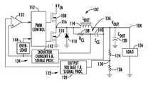
- FIG. 1is a simplified schematic diagram of a DC/DC converter
- FIG. 2illustrates a current sensor in parallel with an inductor
- FIGS. 3 a and 3 billustrate a sensed current, inductor current and output waveform for the circuit of FIG. 2 ;
- FIG. 4illustrates a negative temperature coefficient for an NTC capacitor
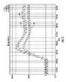
- FIG. 5illustrates current waveforms for a lumped DCR inductor, a current sensor using an NTC capacitor and a current sensor not using an NTC capacitor.
- the current through an output inductor of the power converteris sensed by current sense circuit for a variety of uses.
- Uses such as current mode control, over current protection, current sharing and current monitoringrequire the accurate sensing of the current through the inductor by the current sense circuitry.
- Existing approaches for measuring the inductor current of the power converterall have their advantages and disadvantages. Some of these methods include using a current sense resistor in series with the output inductor to provide real time accurate current signals with higher costs but lower efficiency.
- a sense resistormay also be installed on the high-side FET drain of the power converter. However, this current goes to zero volts during the high-side FET “off” stage and makes it difficult to obtain accurate cycle to cycle current information.
- Another methodinvolves the use of a loss-less RC circuit that is placed in parallel with the inductor and the “lumped” DCR (DC resistance) of the inductor. This method makes use of the respective time constants of these circuits to “pull” inductor current information via the voltage drop across a sensing capacitor.
- the DC/DC converter 102provides a controlled voltage V OUT at node 104 to a load 106 .
- the DC/DC converter 102includes a pair of switching transistors including a high-side switch 108 and a low-side switch 110 connected to receive a source voltage V IN .
- the DC/DC converter 102in other embodiments may include only the high-side switch 108 with a diode substituted in the position of the low-side switch 110 .
- MOSFET transistorsare illustrated, other semiconductor switches may be used as will be understood by one skilled in the art.
- the DC/DC converteradditionally includes an overload detection circuit 144 which uses the sensed current signal from current sensor 136 to prevent overloads.
- the high-side switching transistor 108 and low-side switching transistor 110are provided control signals from a pulse width modulation control circuit 112 .
- the pulse width modulation control circuit 112generates a series of pulse width modulated control pulses for the high-side switch 108 and low-side switch 110 to regulate the output voltage V OUT coupled to load 106 responsive to a current monitored through an inductor 114 .
- the output inductor L OUT 114is connected to the phase node of the DC/DC converter 102 at node 116 between the high-side switch 108 and the low-side switch 110 .
- the inductor 114is connected between the phase node 116 and the output voltage node 104 .
- a diode 118is connected between node 116 and ground.
- An output capacitance C OUT 120is connected in parallel with the load 106 between the output voltage node 104 and ground.
- a voltage regulation loop 122provides a feedback voltage from the output node V OUT through a resistor divider consisting of a resistor 124 connected in series with a resistor 126 between node 104 and ground.
- An output voltage feedback signal processor 128monitors the output voltage from the voltage divider circuit at node 130 .
- the output voltage feedback signal processor 128provides a feedback voltage signal to an inverting input of comparator 132 .
- a current control loop 134provides an input to the non-inverting input of the comparator 132 .
- the current control loop 134includes a current sensor 136 that is connected in parallel with the output inductor 114 to sense the current passing through the inductor 114 .
- the current sensor 136consists of a resistor R CS 138 and an NTC capacitor 140 connected together in series.
- the current sensor 136provides a current control signal back to the PWM control circuitry 112 through an inductor current feedback signal processor 142 to assist in controlling of the power switches 108 and 110 responsive to a sensed current through the inductor 114 .
- all inductorsinclude a winding that is a wire, such as copper, that surrounds a magnetic material or air.
- This wirehas a resistance per unit length that leads to a distributed resistance that can be measured as the DC resistance (DCR) of the inductor.
- DCRDC resistance
- a fairly good model of the practical inductorlumps the distributed winding resistance into a single element DCR that is in series with an ideal inductance L as illustrated in FIG. 2 .
- FIGS. 3 a and 3 billustrate the traces for the load current 302 , the sensed current 304 and the output voltage 306 .
- FIG. 3 athe operation of these wave forms are illustrated in the warm condition, and in the cool condition in FIG. 3 b .
- the DCR of the inductoris smaller resulting in some overshoot of the output voltage and undershoot due to the relatively short RC time constant within the current sense network.
- the illustrations in FIGS. 3 a and 3 bonly represent mismatch due to self heating and not due to a full temperature range that the circuit would typically operate within.
- the L/DCR time constant valuecan change dramatically during normal operation. As the DCR value changes, it will have two major effects. If the DCR value increases, causing L/DCR to be less than R ⁇ C ( ⁇ 1 ⁇ 2 ), then the voltage across the capacitor 140 will be lower than the voltage drop across the inductor's DCR and the regulated response will be slow and potentially cause a low V OUT scenario (UVP) (i.e., an under voltage fault condition on V OUT ). Within the second condition, where DCR has decreased from the nominal value causing L/DCR to be greater than R ⁇ C ( ⁇ 1 > ⁇ 2 ).
- V OUT scenarioi.e., an under voltage fault condition on V OUT
- NTC capacitor 140By using an NTC capacitor for capacitor 140 , a negative temperature coefficient is achieved as illustrated in FIG. 4 such that the capacitance drops when the temperature increases.
- the NTC capacitordemonstrates a more linear response to temperature than current NTC thermisters.
- a PTC capacitorcould be used if the resistance had the opposite temperature characteristics of copper.
- the characteristics of the NTC capacitorcan be used to match the inductor's DCR temperature characteristics.
- the time constant RC provided by the current sensor 136will match the time constant L/DCR of the inductor under all operational temperatures.
- the NTC capacitorsprovide a number of advantages over the use of NTC thermisters since they have a very stable temperature coefficient of approximately ⁇ 4000 ppm (or greater if needed) and are of significantly lower cost (approximately $0.015). This cost savings is especially pronounced for multiphased designs wherein an NTC thermister would be required for each phase.
- the NTC capacitor 140reduces/cancels the time constant mismatching for all operational temperatures.
- the NTC capacitor 140yields a negative temperature coefficient so that the capacitance of the capacitor 140 drops as the temperature increases.
- the NTC capacitor 140demonstrates a more linear response to temperature and requires the resistance 138 to set the time constant ⁇ 2 for the current sensor 136 .
- the temperature characteristics of the NTC capacitor 140can be used to match the inductor's DCR temperature characteristics. By careful design of the NTC capacitor temperature coefficient, the time constant RC will match the time constant L/DCR under all operational temperatures.
- the L/DCR quotienthas a roughly +4000 ppm variability with temperature due to the increase in copper winding resistance.
- the proposed external NTC capacitorwould, at a minimum, require this magnitude of linear variation.
- the coefficientwill need to be higher to compensate for the second order effects such as a decrease in the inductive impedance of temperature and due to temperature gradients where the temperature of the capacitor was slightly different than the temperature in the inductor.
- FIG. 5illustrates a current wave form 502 for the lumped DCR inductor (represented by squares), the wave form 504 for the current sensor using the NTC capacitor (represented by an upside down triangle) and the waveform 506 for a current sensor not using an NTC capacitor (represented by a diamond).
- the AC wave form with a matching capacitor that is an NTC capacitoris indistinguishable from the lumped DCR voltage drop. This simulation assumes that the DC component is compensated for using normal compensation techniques.
- the use of an NTC capacitor 140 within the current sensor 136solves a number of problems within the current sensor.
- the solutionprovides a matched time constant so that rapid changes in the load current can be acted upon for protecting circuit components (for example, an OCP event), accurately monitors the efficiency of the current through the inductor and when used as an input to a control loop, improves transient response.
- the solutionprovides a current sensor having much better linearity as compared to a current sensor using a thermister whose NTC has a much more non linear response as compared to an NTC capacitor.
- the solutionprovides a current sensor having a significantly lower cost as compared to a thermister solution given that the standard capacitor having a cost of approximately $0.002 is replaced with a new NTC capacitor having a cost of approximately $0.015 which provides a negligible cost impact when compared to the use of a current sensor including a thermister having a cost of approximately $0.05.
Landscapes
- Engineering & Computer Science (AREA)
- Power Engineering (AREA)
- Dc-Dc Converters (AREA)
Abstract
Description
Claims (16)
Priority Applications (1)
| Application Number | Priority Date | Filing Date | Title |
|---|---|---|---|
| US12/329,147US8368368B2 (en) | 2007-12-06 | 2008-12-05 | System and method for improving inductor current sensing accuracy of a DC/DC voltage regulator |
Applications Claiming Priority (2)
| Application Number | Priority Date | Filing Date | Title |
|---|---|---|---|
| US99281707P | 2007-12-06 | 2007-12-06 | |
| US12/329,147US8368368B2 (en) | 2007-12-06 | 2008-12-05 | System and method for improving inductor current sensing accuracy of a DC/DC voltage regulator |
Publications (2)
| Publication Number | Publication Date |
|---|---|
| US20090146635A1 US20090146635A1 (en) | 2009-06-11 |
| US8368368B2true US8368368B2 (en) | 2013-02-05 |
Family
ID=40720938
Family Applications (1)
| Application Number | Title | Priority Date | Filing Date |
|---|---|---|---|
| US12/329,147Expired - Fee RelatedUS8368368B2 (en) | 2007-12-06 | 2008-12-05 | System and method for improving inductor current sensing accuracy of a DC/DC voltage regulator |
Country Status (5)
| Country | Link |
|---|---|
| US (1) | US8368368B2 (en) |
| KR (1) | KR20100089820A (en) |
| CN (1) | CN101842970A (en) |
| TW (1) | TW200941907A (en) |
| WO (1) | WO2009076197A2 (en) |
Cited By (6)
| Publication number | Priority date | Publication date | Assignee | Title |
|---|---|---|---|---|
| US8493045B2 (en)* | 2010-12-22 | 2013-07-23 | Atmel Corporation | Voltage regulator configuration |
| US20160072500A1 (en)* | 2014-09-04 | 2016-03-10 | Kabushiki Kaisha Toshiba | Controller, converter and control method |
| US20160349288A1 (en)* | 2015-05-28 | 2016-12-01 | Lenovo Enterprise Solutions (Singapore) Pte. Ltd. | Sensing current of a dc-dc converter |
| US9590506B2 (en) | 2014-12-15 | 2017-03-07 | Nxp Usa, Inc. | Multiple mode power regulator |
| US9696739B2 (en) | 2014-07-10 | 2017-07-04 | Intersil Americas LLC | Sensing a switching-power-supply phase current |
| US20220131464A1 (en)* | 2019-07-09 | 2022-04-28 | Murata Manufacturing Co., Ltd | Switching power supply apparatus |
Families Citing this family (45)
| Publication number | Priority date | Publication date | Assignee | Title |
|---|---|---|---|---|
| US7137980B2 (en) | 1998-10-23 | 2006-11-21 | Sherwood Services Ag | Method and system for controlling output of RF medical generator |
| AU2004235739B2 (en) | 2003-05-01 | 2010-06-17 | Covidien Ag | Method and system for programming and controlling an electrosurgical generator system |
| WO2005050151A1 (en) | 2003-10-23 | 2005-06-02 | Sherwood Services Ag | Thermocouple measurement circuit |
| US7396336B2 (en) | 2003-10-30 | 2008-07-08 | Sherwood Services Ag | Switched resonant ultrasonic power amplifier system |
| US7947039B2 (en) | 2005-12-12 | 2011-05-24 | Covidien Ag | Laparoscopic apparatus for performing electrosurgical procedures |
| CA2574934C (en) | 2006-01-24 | 2015-12-29 | Sherwood Services Ag | System and method for closed loop monitoring of monopolar electrosurgical apparatus |
| US7782035B2 (en)* | 2007-03-28 | 2010-08-24 | Intersil Americas Inc. | Controller and driver communication for switching regulators |
| CN101685314B (en)* | 2008-09-23 | 2014-07-09 | 成都芯源系统有限公司 | Self-adaptive voltage positioning direct current voltage stabilizer and control method thereof |
| US8262652B2 (en) | 2009-01-12 | 2012-09-11 | Tyco Healthcare Group Lp | Imaginary impedance process monitoring and intelligent shut-off |
| WO2011084809A2 (en)* | 2009-12-21 | 2011-07-14 | Invensys Rail Corporation | An algorithmic approach to pwm smps current sensing and system validation |
| US8454590B2 (en)* | 2010-02-26 | 2013-06-04 | Covidien Lp | Enhanced lossless current sense circuit |
| US8957651B2 (en)* | 2010-12-06 | 2015-02-17 | Microchip Technology Incorporated | User-configurable, efficiency-optimizing, power/energy conversion switch-mode power supply with a serial communications interface |
| US8823352B2 (en)* | 2011-07-11 | 2014-09-02 | Linear Technology Corporation | Switching power supply having separate AC and DC current sensing paths |
| CN102967755A (en)* | 2011-09-01 | 2013-03-13 | 鸿富锦精密工业(深圳)有限公司 | Inductive current detecting circuit |
| KR101864895B1 (en) | 2011-09-06 | 2018-06-05 | 현대모비스 주식회사 | Inductor module integrated with current sensor and manufacturing method thereof |
| CN103025049A (en) | 2011-09-26 | 2013-04-03 | 鸿富锦精密工业(深圳)有限公司 | Printed circuit board |
| CN103033673A (en)* | 2011-09-30 | 2013-04-10 | 鸿富锦精密工业(深圳)有限公司 | Inductor voltage testing device |
| KR101965892B1 (en) | 2012-03-05 | 2019-04-08 | 삼성디스플레이 주식회사 | DC-DC Converter and Organic Light Emitting Display Device Using the same |
| KR101928020B1 (en) | 2012-07-17 | 2019-03-13 | 삼성디스플레이 주식회사 | Voltage Generator and Organic Light Emitting Display Device Using the same |
| CN103675404B (en)* | 2012-09-05 | 2018-07-10 | 快捷半导体(苏州)有限公司 | Sensing and the methods, devices and systems for adjusting the inductor current in inductor |
| US9548651B2 (en)* | 2013-02-22 | 2017-01-17 | Texas Instruments Incorporated | Advanced control circuit for switched-mode DC-DC converter |
| US10842563B2 (en) | 2013-03-15 | 2020-11-24 | Covidien Lp | System and method for power control of electrosurgical resonant inverters |
| CN103178712A (en)* | 2013-03-25 | 2013-06-26 | 常州大学 | Device and method for suppressing low-frequency fluctuations in pulse-span-cycle-modulated switching converters |
| US9872719B2 (en) | 2013-07-24 | 2018-01-23 | Covidien Lp | Systems and methods for generating electrosurgical energy using a multistage power converter |
| US9655670B2 (en) | 2013-07-29 | 2017-05-23 | Covidien Lp | Systems and methods for measuring tissue impedance through an electrosurgical cable |
| CN104426373A (en)* | 2013-08-30 | 2015-03-18 | 天钰科技股份有限公司 | Switching Power Supply Voltage Regulator |
| CN103472280A (en)* | 2013-09-12 | 2013-12-25 | 昆山新金福精密电子有限公司 | Voltage detection circuit |
| TWI539753B (en) | 2013-10-07 | 2016-06-21 | 宏碁股份有限公司 | Electronic device |
| US9627969B2 (en) | 2014-05-27 | 2017-04-18 | Infineon Technologies Austria Ag | Inductor current measurement compensation for switching voltage regulators |
| US9748843B2 (en)* | 2014-09-24 | 2017-08-29 | Linear Technology Corporation | DCR inductor current-sensing in four-switch buck-boost converters |
| JP6245187B2 (en)* | 2015-02-02 | 2017-12-13 | 株式会社村田製作所 | Power inductor evaluation apparatus and power inductor evaluation program |
| TWI552480B (en)* | 2015-03-03 | 2016-10-01 | 晶豪科技股份有限公司 | Switching charger |
| US10338669B2 (en)* | 2015-10-27 | 2019-07-02 | Dell Products, L.P. | Current sense accuracy improvement for MOSFET RDS (on) sense based voltage regulator by adaptive temperature compensation |
| CN108886320B (en)* | 2016-04-08 | 2019-12-17 | Abb瑞士股份有限公司 | Converter unit including an energy converter in parallel with a clamp inductor |
| CN106533382B (en)* | 2016-12-01 | 2019-02-19 | 哈尔滨工业大学 | T-type impedance matching circuit applied to ultra-high frequency DC/DC power converter and parameter design method of the matching circuit |
| US10116212B2 (en) | 2017-03-13 | 2018-10-30 | Dell Products, L.P. | Voltage regulation based on current sensing in MOSFET drain-to-source resistance in on-state RDS(ON) |
| CN107422773B (en)* | 2017-08-07 | 2019-02-05 | 湖南国科微电子股份有限公司 | Digital low-dropout regulator |
| PL233980B1 (en)* | 2017-12-27 | 2019-12-31 | Politechnika Slaska | Method for measuring the average value in input current of the single and multi-phase voltage increasing converter |
| US10824214B2 (en)* | 2018-03-05 | 2020-11-03 | Dell Products L.P. | Systems and methods for maximizing multi-phase voltage regulator efficiency using operational modes in which phases operate in fully-enabled mode and light-load mode |
| US10958167B2 (en) | 2018-08-08 | 2021-03-23 | Qualcomm Incorporated | Current sensing in an on-die direct current-direct current (DC-DC) converter for measuring delivered power |
| US11522451B2 (en)* | 2019-12-13 | 2022-12-06 | Alpha And Omega Semiconductor (Cayman) Ltd. | Inductor binning enhanced current sense |
| CN110868069B (en)* | 2019-12-13 | 2021-11-30 | 北京集创北方科技股份有限公司 | Voltage adjusting device, chip and electronic equipment |
| KR102829338B1 (en)* | 2020-04-01 | 2025-07-02 | 현대자동차주식회사 | Dc-dc converter |
| US12226143B2 (en) | 2020-06-22 | 2025-02-18 | Covidien Lp | Universal surgical footswitch toggling |
| CN112600170A (en)* | 2020-12-10 | 2021-04-02 | 昱能科技股份有限公司 | Circuit protection method, system and device |
Citations (9)
| Publication number | Priority date | Publication date | Assignee | Title |
|---|---|---|---|---|
| US5638252A (en)* | 1995-06-14 | 1997-06-10 | Hughes Aircraft Company | Electrical device and method utilizing a positive-temperature-coefficient ferroelectric capacitor |
| US5982160A (en)* | 1998-12-24 | 1999-11-09 | Harris Corporation | DC-to-DC converter with inductor current sensing and related methods |
| US20020070399A1 (en)* | 2000-08-30 | 2002-06-13 | Alps Electric Co., Ltd. | Thin film capacitor for temperature compensation |
| US6522087B1 (en)* | 2001-07-24 | 2003-02-18 | Chao-Cheng Lu | Ultra-high voltage impulse generator |
| US6879136B1 (en)* | 2003-10-31 | 2005-04-12 | Analog Devices, Inc. | Inductor current emulation circuit for switching power supply |
| US20060189003A1 (en)* | 2002-09-26 | 2006-08-24 | Dougherty T K | Temperature-compensated ferroelectric capacitor device, and its fabrication |
| US20070241727A1 (en)* | 2006-04-18 | 2007-10-18 | Dell Products L.P. | Temperature-compensated inductor DCR dynamic current sensing |
| US7345460B2 (en)* | 2005-02-28 | 2008-03-18 | Board Of Supervisors Of Louisiana State University And Agricultural And Mechanical College | Thermal compensation method for CMOS digital-integrated circuits using temperature-adaptive digital DC/DC converter |
| US7710748B2 (en)* | 2004-04-13 | 2010-05-04 | Texas Instruments (Cork) Limited | AC/DC converter comprising plural converters in cascade |
Family Cites Families (5)
| Publication number | Priority date | Publication date | Assignee | Title |
|---|---|---|---|---|
| EP0741447A3 (en)* | 1995-05-04 | 1997-04-16 | At & T Corp | Circuit and method for controlling a synchronous recifier converter |
| US5912552A (en)* | 1997-02-12 | 1999-06-15 | Kabushiki Kaisha Toyoda Jidoshokki Seisakusho | DC to DC converter with high efficiency for light loads |
| AU3103300A (en)* | 1998-12-03 | 2000-06-19 | Virginia Tech Intellectual Properties, Inc. | Voltage regulator modules (vrm) with current sensing and current sharing |
| US6377032B1 (en)* | 2000-07-20 | 2002-04-23 | Semtech Corporation | Method and apparatus for virtual current sensing in DC-DC switched mode power supplies |
| US6841983B2 (en)* | 2002-11-14 | 2005-01-11 | Fyre Storm, Inc. | Digital signal to pulse converter and method of digital signal to pulse conversion |
- 2008
- 2008-12-05USUS12/329,147patent/US8368368B2/ennot_activeExpired - Fee Related
- 2008-12-05WOPCT/US2008/085668patent/WO2009076197A2/enactiveApplication Filing
- 2008-12-05KRKR1020107007619Apatent/KR20100089820A/ennot_activeWithdrawn
- 2008-12-05CNCN200880114565Apatent/CN101842970A/enactivePending
- 2008-12-05TWTW097147234Apatent/TW200941907A/enunknown
Patent Citations (10)
| Publication number | Priority date | Publication date | Assignee | Title |
|---|---|---|---|---|
| US5638252A (en)* | 1995-06-14 | 1997-06-10 | Hughes Aircraft Company | Electrical device and method utilizing a positive-temperature-coefficient ferroelectric capacitor |
| US5982160A (en)* | 1998-12-24 | 1999-11-09 | Harris Corporation | DC-to-DC converter with inductor current sensing and related methods |
| US20020070399A1 (en)* | 2000-08-30 | 2002-06-13 | Alps Electric Co., Ltd. | Thin film capacitor for temperature compensation |
| US6522087B1 (en)* | 2001-07-24 | 2003-02-18 | Chao-Cheng Lu | Ultra-high voltage impulse generator |
| US20060189003A1 (en)* | 2002-09-26 | 2006-08-24 | Dougherty T K | Temperature-compensated ferroelectric capacitor device, and its fabrication |
| US6879136B1 (en)* | 2003-10-31 | 2005-04-12 | Analog Devices, Inc. | Inductor current emulation circuit for switching power supply |
| US7710748B2 (en)* | 2004-04-13 | 2010-05-04 | Texas Instruments (Cork) Limited | AC/DC converter comprising plural converters in cascade |
| US7345460B2 (en)* | 2005-02-28 | 2008-03-18 | Board Of Supervisors Of Louisiana State University And Agricultural And Mechanical College | Thermal compensation method for CMOS digital-integrated circuits using temperature-adaptive digital DC/DC converter |
| US20070241727A1 (en)* | 2006-04-18 | 2007-10-18 | Dell Products L.P. | Temperature-compensated inductor DCR dynamic current sensing |
| US7358710B2 (en)* | 2006-04-18 | 2008-04-15 | Dell Products L.P. | Temperature-compensated inductor DCR dynamic current sensing |
Non-Patent Citations (2)
| Title |
|---|
| PCT: International Search Report of PCT/US2008/085668; International Publication No. WO 2009/076197; Aug. 31, 2009; 4 pages. |
| PCT: Written Opinion of the International Searching Authority of PCT/US2008/085668; International Publication No. WO 2009/076197; Aug. 31, 2009; 4 pages. |
Cited By (9)
| Publication number | Priority date | Publication date | Assignee | Title |
|---|---|---|---|---|
| US8493045B2 (en)* | 2010-12-22 | 2013-07-23 | Atmel Corporation | Voltage regulator configuration |
| US9696739B2 (en) | 2014-07-10 | 2017-07-04 | Intersil Americas LLC | Sensing a switching-power-supply phase current |
| US9720429B2 (en) | 2014-07-10 | 2017-08-01 | Intersil Americas LLC | Sensing a switching-power-supply phase current |
| US20160072500A1 (en)* | 2014-09-04 | 2016-03-10 | Kabushiki Kaisha Toshiba | Controller, converter and control method |
| US9590506B2 (en) | 2014-12-15 | 2017-03-07 | Nxp Usa, Inc. | Multiple mode power regulator |
| US20160349288A1 (en)* | 2015-05-28 | 2016-12-01 | Lenovo Enterprise Solutions (Singapore) Pte. Ltd. | Sensing current of a dc-dc converter |
| US9618539B2 (en)* | 2015-05-28 | 2017-04-11 | Lenovo Enterprise Solutions (Singapore) Pte. Ltd. | Sensing current of a DC-DC converter |
| US20220131464A1 (en)* | 2019-07-09 | 2022-04-28 | Murata Manufacturing Co., Ltd | Switching power supply apparatus |
| US11923774B2 (en)* | 2019-07-09 | 2024-03-05 | Murata Manufacturing Co., Ltd. | Switching power supply apparatus |
Also Published As
| Publication number | Publication date |
|---|---|
| WO2009076197A3 (en) | 2009-10-22 |
| US20090146635A1 (en) | 2009-06-11 |
| TW200941907A (en) | 2009-10-01 |
| WO2009076197A2 (en) | 2009-06-18 |
| KR20100089820A (en) | 2010-08-12 |
| CN101842970A (en) | 2010-09-22 |
Similar Documents
| Publication | Publication Date | Title |
|---|---|---|
| US8368368B2 (en) | System and method for improving inductor current sensing accuracy of a DC/DC voltage regulator | |
| JP3254199B2 (en) | DC-DC converter having inductor current detector and adjustment method thereof | |
| KR100578908B1 (en) | Thermally compensated current sensing of intrinsic power converter devices | |
| US8363363B2 (en) | DC-DC converters having improved current sensing and related methods | |
| TWI404316B (en) | Dc-dc converters having improved current sensing and related methods | |
| US6127814A (en) | System to protect switch mode DC/DC converters against overload current | |
| CN115133790B (en) | Multiphase power supply and method for generating output voltage thereof | |
| CN105137148A (en) | Inductor current measurement compensation for switching voltage regulators | |
| JP2004535149A (en) | Inductor current sensing and related methods in insulation switching regulators | |
| US9531265B1 (en) | Capacitive current-mode control of a DC/DC converter | |
| US9696739B2 (en) | Sensing a switching-power-supply phase current | |
| KR101723477B1 (en) | Switching topology for connecting two nodes in electronic system | |
| US9306455B2 (en) | Hysteretic power converter with switch gate current sense | |
| US10650946B1 (en) | Trimming method of DCR sensing circuits | |
| JP2010220454A (en) | Dc-dc converter and semiconductor integrated circuit for control | |
| Chang | Combined lossless current sensing for current mode control | |
| KR20250114882A (en) | DC-DC Buck converter | |
| Burket et al. | New NTC MLCC capacitor for improved transient performance in multiphase voltage regulators | |
| Protection et al. | Dual Out-of-Phase Synchronous Buck Controller with Current Limit | |
| WO2005031957A1 (en) | A switch mode power supply |
Legal Events
| Date | Code | Title | Description |
|---|---|---|---|
| AS | Assignment | Owner name:INTERSIL AMERICAS INC., CALIFORNIA Free format text:ASSIGNMENT OF ASSIGNORS INTEREST;ASSIGNORS:QIU, WEIHONG;BURKET, CHRIS T.;MEHAS, GUSTAVO JAMES;REEL/FRAME:021984/0866;SIGNING DATES FROM 20081125 TO 20081205 Owner name:INTERSIL AMERICAS INC., CALIFORNIA Free format text:ASSIGNMENT OF ASSIGNORS INTEREST;ASSIGNORS:QIU, WEIHONG;BURKET, CHRIS T.;MEHAS, GUSTAVO JAMES;SIGNING DATES FROM 20081125 TO 20081205;REEL/FRAME:021984/0866 | |
| AS | Assignment | Owner name:MORGAN STANLEY & CO. INCORPORATED,NEW YORK Free format text:SECURITY AGREEMENT;ASSIGNORS:INTERSIL CORPORATION;TECHWELL, INC.;INTERSIL COMMUNICATIONS, INC.;AND OTHERS;REEL/FRAME:024329/0411 Effective date:20100427 Owner name:MORGAN STANLEY & CO. INCORPORATED, NEW YORK Free format text:SECURITY AGREEMENT;ASSIGNORS:INTERSIL CORPORATION;TECHWELL, INC.;INTERSIL COMMUNICATIONS, INC.;AND OTHERS;REEL/FRAME:024329/0411 Effective date:20100427 | |
| AS | Assignment | Owner name:INTERSIL AMERICAS LLC, CALIFORNIA Free format text:CHANGE OF NAME;ASSIGNOR:INTERSIL AMERICAS INC.;REEL/FRAME:033119/0484 Effective date:20111223 | |
| REMI | Maintenance fee reminder mailed | ||
| LAPS | Lapse for failure to pay maintenance fees | ||
| STCH | Information on status: patent discontinuation | Free format text:PATENT EXPIRED DUE TO NONPAYMENT OF MAINTENANCE FEES UNDER 37 CFR 1.362 | |
| FP | Lapsed due to failure to pay maintenance fee | Effective date:20170205 |