US8366776B2 - Vertebral implants having predetermined angular correction and method of use - Google Patents
Vertebral implants having predetermined angular correction and method of useDownload PDFInfo
- Publication number
- US8366776B2 US8366776B2US11/403,351US40335106AUS8366776B2US 8366776 B2US8366776 B2US 8366776B2US 40335106 AUS40335106 AUS 40335106AUS 8366776 B2US8366776 B2US 8366776B2
- Authority
- US
- United States
- Prior art keywords
- implant
- angle
- inferior
- superior
- bodies
- Prior art date
- Legal status (The legal status is an assumption and is not a legal conclusion. Google has not performed a legal analysis and makes no representation as to the accuracy of the status listed.)
- Active, expires
Links
Images


Classifications
- A—HUMAN NECESSITIES
- A61—MEDICAL OR VETERINARY SCIENCE; HYGIENE
- A61F—FILTERS IMPLANTABLE INTO BLOOD VESSELS; PROSTHESES; DEVICES PROVIDING PATENCY TO, OR PREVENTING COLLAPSING OF, TUBULAR STRUCTURES OF THE BODY, e.g. STENTS; ORTHOPAEDIC, NURSING OR CONTRACEPTIVE DEVICES; FOMENTATION; TREATMENT OR PROTECTION OF EYES OR EARS; BANDAGES, DRESSINGS OR ABSORBENT PADS; FIRST-AID KITS
- A61F2/00—Filters implantable into blood vessels; Prostheses, i.e. artificial substitutes or replacements for parts of the body; Appliances for connecting them with the body; Devices providing patency to, or preventing collapsing of, tubular structures of the body, e.g. stents
- A61F2/02—Prostheses implantable into the body
- A61F2/30—Joints
- A61F2/44—Joints for the spine, e.g. vertebrae, spinal discs
- A61F2/4455—Joints for the spine, e.g. vertebrae, spinal discs for the fusion of spinal bodies, e.g. intervertebral fusion of adjacent spinal bodies, e.g. fusion cages
- A61F2/4465—Joints for the spine, e.g. vertebrae, spinal discs for the fusion of spinal bodies, e.g. intervertebral fusion of adjacent spinal bodies, e.g. fusion cages having a circular or kidney shaped cross-section substantially perpendicular to the axis of the spine
- A—HUMAN NECESSITIES
- A61—MEDICAL OR VETERINARY SCIENCE; HYGIENE
- A61F—FILTERS IMPLANTABLE INTO BLOOD VESSELS; PROSTHESES; DEVICES PROVIDING PATENCY TO, OR PREVENTING COLLAPSING OF, TUBULAR STRUCTURES OF THE BODY, e.g. STENTS; ORTHOPAEDIC, NURSING OR CONTRACEPTIVE DEVICES; FOMENTATION; TREATMENT OR PROTECTION OF EYES OR EARS; BANDAGES, DRESSINGS OR ABSORBENT PADS; FIRST-AID KITS
- A61F2/00—Filters implantable into blood vessels; Prostheses, i.e. artificial substitutes or replacements for parts of the body; Appliances for connecting them with the body; Devices providing patency to, or preventing collapsing of, tubular structures of the body, e.g. stents
- A61F2/02—Prostheses implantable into the body
- A61F2/30—Joints
- A61F2/44—Joints for the spine, e.g. vertebrae, spinal discs
- A—HUMAN NECESSITIES
- A61—MEDICAL OR VETERINARY SCIENCE; HYGIENE
- A61F—FILTERS IMPLANTABLE INTO BLOOD VESSELS; PROSTHESES; DEVICES PROVIDING PATENCY TO, OR PREVENTING COLLAPSING OF, TUBULAR STRUCTURES OF THE BODY, e.g. STENTS; ORTHOPAEDIC, NURSING OR CONTRACEPTIVE DEVICES; FOMENTATION; TREATMENT OR PROTECTION OF EYES OR EARS; BANDAGES, DRESSINGS OR ABSORBENT PADS; FIRST-AID KITS
- A61F2/00—Filters implantable into blood vessels; Prostheses, i.e. artificial substitutes or replacements for parts of the body; Appliances for connecting them with the body; Devices providing patency to, or preventing collapsing of, tubular structures of the body, e.g. stents
- A61F2/02—Prostheses implantable into the body
- A61F2/28—Bones
- A61F2002/2835—Bone graft implants for filling a bony defect or an endoprosthesis cavity, e.g. by synthetic material or biological material
- A—HUMAN NECESSITIES
- A61—MEDICAL OR VETERINARY SCIENCE; HYGIENE
- A61F—FILTERS IMPLANTABLE INTO BLOOD VESSELS; PROSTHESES; DEVICES PROVIDING PATENCY TO, OR PREVENTING COLLAPSING OF, TUBULAR STRUCTURES OF THE BODY, e.g. STENTS; ORTHOPAEDIC, NURSING OR CONTRACEPTIVE DEVICES; FOMENTATION; TREATMENT OR PROTECTION OF EYES OR EARS; BANDAGES, DRESSINGS OR ABSORBENT PADS; FIRST-AID KITS
- A61F2/00—Filters implantable into blood vessels; Prostheses, i.e. artificial substitutes or replacements for parts of the body; Appliances for connecting them with the body; Devices providing patency to, or preventing collapsing of, tubular structures of the body, e.g. stents
- A61F2/02—Prostheses implantable into the body
- A61F2/30—Joints
- A61F2002/30001—Additional features of subject-matter classified in A61F2/28, A61F2/30 and subgroups thereof
- A61F2002/30108—Shapes
- A61F2002/3011—Cross-sections or two-dimensional shapes
- A61F2002/30112—Rounded shapes, e.g. with rounded corners
- A61F2002/30131—Rounded shapes, e.g. with rounded corners horseshoe- or crescent- or C-shaped or U-shaped
- A—HUMAN NECESSITIES
- A61—MEDICAL OR VETERINARY SCIENCE; HYGIENE
- A61F—FILTERS IMPLANTABLE INTO BLOOD VESSELS; PROSTHESES; DEVICES PROVIDING PATENCY TO, OR PREVENTING COLLAPSING OF, TUBULAR STRUCTURES OF THE BODY, e.g. STENTS; ORTHOPAEDIC, NURSING OR CONTRACEPTIVE DEVICES; FOMENTATION; TREATMENT OR PROTECTION OF EYES OR EARS; BANDAGES, DRESSINGS OR ABSORBENT PADS; FIRST-AID KITS
- A61F2/00—Filters implantable into blood vessels; Prostheses, i.e. artificial substitutes or replacements for parts of the body; Appliances for connecting them with the body; Devices providing patency to, or preventing collapsing of, tubular structures of the body, e.g. stents
- A61F2/02—Prostheses implantable into the body
- A61F2/30—Joints
- A61F2002/30001—Additional features of subject-matter classified in A61F2/28, A61F2/30 and subgroups thereof
- A61F2002/30108—Shapes
- A61F2002/3011—Cross-sections or two-dimensional shapes
- A61F2002/30112—Rounded shapes, e.g. with rounded corners
- A61F2002/30133—Rounded shapes, e.g. with rounded corners kidney-shaped or bean-shaped
- A—HUMAN NECESSITIES
- A61—MEDICAL OR VETERINARY SCIENCE; HYGIENE
- A61F—FILTERS IMPLANTABLE INTO BLOOD VESSELS; PROSTHESES; DEVICES PROVIDING PATENCY TO, OR PREVENTING COLLAPSING OF, TUBULAR STRUCTURES OF THE BODY, e.g. STENTS; ORTHOPAEDIC, NURSING OR CONTRACEPTIVE DEVICES; FOMENTATION; TREATMENT OR PROTECTION OF EYES OR EARS; BANDAGES, DRESSINGS OR ABSORBENT PADS; FIRST-AID KITS
- A61F2/00—Filters implantable into blood vessels; Prostheses, i.e. artificial substitutes or replacements for parts of the body; Appliances for connecting them with the body; Devices providing patency to, or preventing collapsing of, tubular structures of the body, e.g. stents
- A61F2/02—Prostheses implantable into the body
- A61F2/30—Joints
- A61F2002/30001—Additional features of subject-matter classified in A61F2/28, A61F2/30 and subgroups thereof
- A61F2002/30316—The prosthesis having different structural features at different locations within the same prosthesis; Connections between prosthetic parts; Special structural features of bone or joint prostheses not otherwise provided for
- A61F2002/30329—Connections or couplings between prosthetic parts, e.g. between modular parts; Connecting elements
- A61F2002/30331—Connections or couplings between prosthetic parts, e.g. between modular parts; Connecting elements made by longitudinally pushing a protrusion into a complementarily-shaped recess, e.g. held by friction fit
- A—HUMAN NECESSITIES
- A61—MEDICAL OR VETERINARY SCIENCE; HYGIENE
- A61F—FILTERS IMPLANTABLE INTO BLOOD VESSELS; PROSTHESES; DEVICES PROVIDING PATENCY TO, OR PREVENTING COLLAPSING OF, TUBULAR STRUCTURES OF THE BODY, e.g. STENTS; ORTHOPAEDIC, NURSING OR CONTRACEPTIVE DEVICES; FOMENTATION; TREATMENT OR PROTECTION OF EYES OR EARS; BANDAGES, DRESSINGS OR ABSORBENT PADS; FIRST-AID KITS
- A61F2/00—Filters implantable into blood vessels; Prostheses, i.e. artificial substitutes or replacements for parts of the body; Appliances for connecting them with the body; Devices providing patency to, or preventing collapsing of, tubular structures of the body, e.g. stents
- A61F2/02—Prostheses implantable into the body
- A61F2/30—Joints
- A61F2002/30001—Additional features of subject-matter classified in A61F2/28, A61F2/30 and subgroups thereof
- A61F2002/30316—The prosthesis having different structural features at different locations within the same prosthesis; Connections between prosthetic parts; Special structural features of bone or joint prostheses not otherwise provided for
- A61F2002/30329—Connections or couplings between prosthetic parts, e.g. between modular parts; Connecting elements
- A61F2002/30383—Connections or couplings between prosthetic parts, e.g. between modular parts; Connecting elements made by laterally inserting a protrusion, e.g. a rib into a complementarily-shaped groove
- A61F2002/30387—Dovetail connection
- A—HUMAN NECESSITIES
- A61—MEDICAL OR VETERINARY SCIENCE; HYGIENE
- A61F—FILTERS IMPLANTABLE INTO BLOOD VESSELS; PROSTHESES; DEVICES PROVIDING PATENCY TO, OR PREVENTING COLLAPSING OF, TUBULAR STRUCTURES OF THE BODY, e.g. STENTS; ORTHOPAEDIC, NURSING OR CONTRACEPTIVE DEVICES; FOMENTATION; TREATMENT OR PROTECTION OF EYES OR EARS; BANDAGES, DRESSINGS OR ABSORBENT PADS; FIRST-AID KITS
- A61F2/00—Filters implantable into blood vessels; Prostheses, i.e. artificial substitutes or replacements for parts of the body; Appliances for connecting them with the body; Devices providing patency to, or preventing collapsing of, tubular structures of the body, e.g. stents
- A61F2/02—Prostheses implantable into the body
- A61F2/30—Joints
- A61F2002/30001—Additional features of subject-matter classified in A61F2/28, A61F2/30 and subgroups thereof
- A61F2002/30316—The prosthesis having different structural features at different locations within the same prosthesis; Connections between prosthetic parts; Special structural features of bone or joint prostheses not otherwise provided for
- A61F2002/30329—Connections or couplings between prosthetic parts, e.g. between modular parts; Connecting elements
- A61F2002/30476—Connections or couplings between prosthetic parts, e.g. between modular parts; Connecting elements locked by an additional locking mechanism
- A61F2002/305—Snap connection
- A—HUMAN NECESSITIES
- A61—MEDICAL OR VETERINARY SCIENCE; HYGIENE
- A61F—FILTERS IMPLANTABLE INTO BLOOD VESSELS; PROSTHESES; DEVICES PROVIDING PATENCY TO, OR PREVENTING COLLAPSING OF, TUBULAR STRUCTURES OF THE BODY, e.g. STENTS; ORTHOPAEDIC, NURSING OR CONTRACEPTIVE DEVICES; FOMENTATION; TREATMENT OR PROTECTION OF EYES OR EARS; BANDAGES, DRESSINGS OR ABSORBENT PADS; FIRST-AID KITS
- A61F2/00—Filters implantable into blood vessels; Prostheses, i.e. artificial substitutes or replacements for parts of the body; Appliances for connecting them with the body; Devices providing patency to, or preventing collapsing of, tubular structures of the body, e.g. stents
- A61F2/02—Prostheses implantable into the body
- A61F2/30—Joints
- A61F2002/30001—Additional features of subject-matter classified in A61F2/28, A61F2/30 and subgroups thereof
- A61F2002/30316—The prosthesis having different structural features at different locations within the same prosthesis; Connections between prosthetic parts; Special structural features of bone or joint prostheses not otherwise provided for
- A61F2002/30535—Special structural features of bone or joint prostheses not otherwise provided for
- A61F2002/30599—Special structural features of bone or joint prostheses not otherwise provided for stackable
- A—HUMAN NECESSITIES
- A61—MEDICAL OR VETERINARY SCIENCE; HYGIENE
- A61F—FILTERS IMPLANTABLE INTO BLOOD VESSELS; PROSTHESES; DEVICES PROVIDING PATENCY TO, OR PREVENTING COLLAPSING OF, TUBULAR STRUCTURES OF THE BODY, e.g. STENTS; ORTHOPAEDIC, NURSING OR CONTRACEPTIVE DEVICES; FOMENTATION; TREATMENT OR PROTECTION OF EYES OR EARS; BANDAGES, DRESSINGS OR ABSORBENT PADS; FIRST-AID KITS
- A61F2/00—Filters implantable into blood vessels; Prostheses, i.e. artificial substitutes or replacements for parts of the body; Appliances for connecting them with the body; Devices providing patency to, or preventing collapsing of, tubular structures of the body, e.g. stents
- A61F2/02—Prostheses implantable into the body
- A61F2/30—Joints
- A61F2002/30001—Additional features of subject-matter classified in A61F2/28, A61F2/30 and subgroups thereof
- A61F2002/30316—The prosthesis having different structural features at different locations within the same prosthesis; Connections between prosthetic parts; Special structural features of bone or joint prostheses not otherwise provided for
- A61F2002/30535—Special structural features of bone or joint prostheses not otherwise provided for
- A61F2002/30604—Special structural features of bone or joint prostheses not otherwise provided for modular
- A61F2002/30616—Sets comprising a plurality of prosthetic parts of different sizes or orientations
- A—HUMAN NECESSITIES
- A61—MEDICAL OR VETERINARY SCIENCE; HYGIENE
- A61F—FILTERS IMPLANTABLE INTO BLOOD VESSELS; PROSTHESES; DEVICES PROVIDING PATENCY TO, OR PREVENTING COLLAPSING OF, TUBULAR STRUCTURES OF THE BODY, e.g. STENTS; ORTHOPAEDIC, NURSING OR CONTRACEPTIVE DEVICES; FOMENTATION; TREATMENT OR PROTECTION OF EYES OR EARS; BANDAGES, DRESSINGS OR ABSORBENT PADS; FIRST-AID KITS
- A61F2/00—Filters implantable into blood vessels; Prostheses, i.e. artificial substitutes or replacements for parts of the body; Appliances for connecting them with the body; Devices providing patency to, or preventing collapsing of, tubular structures of the body, e.g. stents
- A61F2/02—Prostheses implantable into the body
- A61F2/30—Joints
- A61F2002/30001—Additional features of subject-matter classified in A61F2/28, A61F2/30 and subgroups thereof
- A61F2002/30667—Features concerning an interaction with the environment or a particular use of the prosthesis
- A61F2002/3071—Identification means; Administration of patients
- A—HUMAN NECESSITIES
- A61—MEDICAL OR VETERINARY SCIENCE; HYGIENE
- A61F—FILTERS IMPLANTABLE INTO BLOOD VESSELS; PROSTHESES; DEVICES PROVIDING PATENCY TO, OR PREVENTING COLLAPSING OF, TUBULAR STRUCTURES OF THE BODY, e.g. STENTS; ORTHOPAEDIC, NURSING OR CONTRACEPTIVE DEVICES; FOMENTATION; TREATMENT OR PROTECTION OF EYES OR EARS; BANDAGES, DRESSINGS OR ABSORBENT PADS; FIRST-AID KITS
- A61F2/00—Filters implantable into blood vessels; Prostheses, i.e. artificial substitutes or replacements for parts of the body; Appliances for connecting them with the body; Devices providing patency to, or preventing collapsing of, tubular structures of the body, e.g. stents
- A61F2/02—Prostheses implantable into the body
- A61F2/30—Joints
- A61F2/30767—Special external or bone-contacting surface, e.g. coating for improving bone ingrowth
- A61F2/30771—Special external or bone-contacting surface, e.g. coating for improving bone ingrowth applied in original prostheses, e.g. holes or grooves
- A61F2002/30772—Apertures or holes, e.g. of circular cross section
- A—HUMAN NECESSITIES
- A61—MEDICAL OR VETERINARY SCIENCE; HYGIENE
- A61F—FILTERS IMPLANTABLE INTO BLOOD VESSELS; PROSTHESES; DEVICES PROVIDING PATENCY TO, OR PREVENTING COLLAPSING OF, TUBULAR STRUCTURES OF THE BODY, e.g. STENTS; ORTHOPAEDIC, NURSING OR CONTRACEPTIVE DEVICES; FOMENTATION; TREATMENT OR PROTECTION OF EYES OR EARS; BANDAGES, DRESSINGS OR ABSORBENT PADS; FIRST-AID KITS
- A61F2/00—Filters implantable into blood vessels; Prostheses, i.e. artificial substitutes or replacements for parts of the body; Appliances for connecting them with the body; Devices providing patency to, or preventing collapsing of, tubular structures of the body, e.g. stents
- A61F2/02—Prostheses implantable into the body
- A61F2/30—Joints
- A61F2/30767—Special external or bone-contacting surface, e.g. coating for improving bone ingrowth
- A61F2/30771—Special external or bone-contacting surface, e.g. coating for improving bone ingrowth applied in original prostheses, e.g. holes or grooves
- A61F2002/30841—Sharp anchoring protrusions for impaction into the bone, e.g. sharp pins, spikes
- A—HUMAN NECESSITIES
- A61—MEDICAL OR VETERINARY SCIENCE; HYGIENE
- A61F—FILTERS IMPLANTABLE INTO BLOOD VESSELS; PROSTHESES; DEVICES PROVIDING PATENCY TO, OR PREVENTING COLLAPSING OF, TUBULAR STRUCTURES OF THE BODY, e.g. STENTS; ORTHOPAEDIC, NURSING OR CONTRACEPTIVE DEVICES; FOMENTATION; TREATMENT OR PROTECTION OF EYES OR EARS; BANDAGES, DRESSINGS OR ABSORBENT PADS; FIRST-AID KITS
- A61F2/00—Filters implantable into blood vessels; Prostheses, i.e. artificial substitutes or replacements for parts of the body; Appliances for connecting them with the body; Devices providing patency to, or preventing collapsing of, tubular structures of the body, e.g. stents
- A61F2/02—Prostheses implantable into the body
- A61F2/30—Joints
- A61F2/44—Joints for the spine, e.g. vertebrae, spinal discs
- A61F2002/448—Joints for the spine, e.g. vertebrae, spinal discs comprising multiple adjacent spinal implants within the same intervertebral space or within the same vertebra, e.g. comprising two adjacent spinal implants
- A—HUMAN NECESSITIES
- A61—MEDICAL OR VETERINARY SCIENCE; HYGIENE
- A61F—FILTERS IMPLANTABLE INTO BLOOD VESSELS; PROSTHESES; DEVICES PROVIDING PATENCY TO, OR PREVENTING COLLAPSING OF, TUBULAR STRUCTURES OF THE BODY, e.g. STENTS; ORTHOPAEDIC, NURSING OR CONTRACEPTIVE DEVICES; FOMENTATION; TREATMENT OR PROTECTION OF EYES OR EARS; BANDAGES, DRESSINGS OR ABSORBENT PADS; FIRST-AID KITS
- A61F2220/00—Fixations or connections for prostheses classified in groups A61F2/00 - A61F2/26 or A61F2/82 or A61F9/00 or A61F11/00 or subgroups thereof
- A61F2220/0025—Connections or couplings between prosthetic parts, e.g. between modular parts; Connecting elements
- A61F2220/0033—Connections or couplings between prosthetic parts, e.g. between modular parts; Connecting elements made by longitudinally pushing a protrusion into a complementary-shaped recess, e.g. held by friction fit
- A—HUMAN NECESSITIES
- A61—MEDICAL OR VETERINARY SCIENCE; HYGIENE
- A61F—FILTERS IMPLANTABLE INTO BLOOD VESSELS; PROSTHESES; DEVICES PROVIDING PATENCY TO, OR PREVENTING COLLAPSING OF, TUBULAR STRUCTURES OF THE BODY, e.g. STENTS; ORTHOPAEDIC, NURSING OR CONTRACEPTIVE DEVICES; FOMENTATION; TREATMENT OR PROTECTION OF EYES OR EARS; BANDAGES, DRESSINGS OR ABSORBENT PADS; FIRST-AID KITS
- A61F2230/00—Geometry of prostheses classified in groups A61F2/00 - A61F2/26 or A61F2/82 or A61F9/00 or A61F11/00 or subgroups thereof
- A61F2230/0002—Two-dimensional shapes, e.g. cross-sections
- A61F2230/0004—Rounded shapes, e.g. with rounded corners
- A61F2230/0013—Horseshoe-shaped, e.g. crescent-shaped, C-shaped, U-shaped
- A—HUMAN NECESSITIES
- A61—MEDICAL OR VETERINARY SCIENCE; HYGIENE
- A61F—FILTERS IMPLANTABLE INTO BLOOD VESSELS; PROSTHESES; DEVICES PROVIDING PATENCY TO, OR PREVENTING COLLAPSING OF, TUBULAR STRUCTURES OF THE BODY, e.g. STENTS; ORTHOPAEDIC, NURSING OR CONTRACEPTIVE DEVICES; FOMENTATION; TREATMENT OR PROTECTION OF EYES OR EARS; BANDAGES, DRESSINGS OR ABSORBENT PADS; FIRST-AID KITS
- A61F2230/00—Geometry of prostheses classified in groups A61F2/00 - A61F2/26 or A61F2/82 or A61F9/00 or A61F11/00 or subgroups thereof
- A61F2230/0002—Two-dimensional shapes, e.g. cross-sections
- A61F2230/0004—Rounded shapes, e.g. with rounded corners
- A61F2230/0015—Kidney-shaped, e.g. bean-shaped
- A—HUMAN NECESSITIES
- A61—MEDICAL OR VETERINARY SCIENCE; HYGIENE
- A61F—FILTERS IMPLANTABLE INTO BLOOD VESSELS; PROSTHESES; DEVICES PROVIDING PATENCY TO, OR PREVENTING COLLAPSING OF, TUBULAR STRUCTURES OF THE BODY, e.g. STENTS; ORTHOPAEDIC, NURSING OR CONTRACEPTIVE DEVICES; FOMENTATION; TREATMENT OR PROTECTION OF EYES OR EARS; BANDAGES, DRESSINGS OR ABSORBENT PADS; FIRST-AID KITS
- A61F2250/00—Special features of prostheses classified in groups A61F2/00 - A61F2/26 or A61F2/82 or A61F9/00 or A61F11/00 or subgroups thereof
- A61F2250/0058—Additional features; Implant or prostheses properties not otherwise provided for
- A61F2250/006—Additional features; Implant or prostheses properties not otherwise provided for modular
- A61F2250/0063—Nested prosthetic parts
- A—HUMAN NECESSITIES
- A61—MEDICAL OR VETERINARY SCIENCE; HYGIENE
- A61F—FILTERS IMPLANTABLE INTO BLOOD VESSELS; PROSTHESES; DEVICES PROVIDING PATENCY TO, OR PREVENTING COLLAPSING OF, TUBULAR STRUCTURES OF THE BODY, e.g. STENTS; ORTHOPAEDIC, NURSING OR CONTRACEPTIVE DEVICES; FOMENTATION; TREATMENT OR PROTECTION OF EYES OR EARS; BANDAGES, DRESSINGS OR ABSORBENT PADS; FIRST-AID KITS
- A61F2250/00—Special features of prostheses classified in groups A61F2/00 - A61F2/26 or A61F2/82 or A61F9/00 or A61F11/00 or subgroups thereof
- A61F2250/0058—Additional features; Implant or prostheses properties not otherwise provided for
- A61F2250/0085—Identification means; Administration of patients
- A—HUMAN NECESSITIES
- A61—MEDICAL OR VETERINARY SCIENCE; HYGIENE
- A61F—FILTERS IMPLANTABLE INTO BLOOD VESSELS; PROSTHESES; DEVICES PROVIDING PATENCY TO, OR PREVENTING COLLAPSING OF, TUBULAR STRUCTURES OF THE BODY, e.g. STENTS; ORTHOPAEDIC, NURSING OR CONTRACEPTIVE DEVICES; FOMENTATION; TREATMENT OR PROTECTION OF EYES OR EARS; BANDAGES, DRESSINGS OR ABSORBENT PADS; FIRST-AID KITS
- A61F2310/00—Prostheses classified in A61F2/28 or A61F2/30 - A61F2/44 being constructed from or coated with a particular material
- A61F2310/00005—The prosthesis being constructed from a particular material
- A61F2310/00011—Metals or alloys
- A61F2310/00017—Iron- or Fe-based alloys, e.g. stainless steel
- A—HUMAN NECESSITIES
- A61—MEDICAL OR VETERINARY SCIENCE; HYGIENE
- A61F—FILTERS IMPLANTABLE INTO BLOOD VESSELS; PROSTHESES; DEVICES PROVIDING PATENCY TO, OR PREVENTING COLLAPSING OF, TUBULAR STRUCTURES OF THE BODY, e.g. STENTS; ORTHOPAEDIC, NURSING OR CONTRACEPTIVE DEVICES; FOMENTATION; TREATMENT OR PROTECTION OF EYES OR EARS; BANDAGES, DRESSINGS OR ABSORBENT PADS; FIRST-AID KITS
- A61F2310/00—Prostheses classified in A61F2/28 or A61F2/30 - A61F2/44 being constructed from or coated with a particular material
- A61F2310/00005—The prosthesis being constructed from a particular material
- A61F2310/00011—Metals or alloys
- A61F2310/00023—Titanium or titanium-based alloys, e.g. Ti-Ni alloys
- A—HUMAN NECESSITIES
- A61—MEDICAL OR VETERINARY SCIENCE; HYGIENE
- A61F—FILTERS IMPLANTABLE INTO BLOOD VESSELS; PROSTHESES; DEVICES PROVIDING PATENCY TO, OR PREVENTING COLLAPSING OF, TUBULAR STRUCTURES OF THE BODY, e.g. STENTS; ORTHOPAEDIC, NURSING OR CONTRACEPTIVE DEVICES; FOMENTATION; TREATMENT OR PROTECTION OF EYES OR EARS; BANDAGES, DRESSINGS OR ABSORBENT PADS; FIRST-AID KITS
- A61F2310/00—Prostheses classified in A61F2/28 or A61F2/30 - A61F2/44 being constructed from or coated with a particular material
- A61F2310/00005—The prosthesis being constructed from a particular material
- A61F2310/00011—Metals or alloys
- A61F2310/00029—Cobalt-based alloys, e.g. Co-Cr alloys or Vitallium
- A—HUMAN NECESSITIES
- A61—MEDICAL OR VETERINARY SCIENCE; HYGIENE
- A61F—FILTERS IMPLANTABLE INTO BLOOD VESSELS; PROSTHESES; DEVICES PROVIDING PATENCY TO, OR PREVENTING COLLAPSING OF, TUBULAR STRUCTURES OF THE BODY, e.g. STENTS; ORTHOPAEDIC, NURSING OR CONTRACEPTIVE DEVICES; FOMENTATION; TREATMENT OR PROTECTION OF EYES OR EARS; BANDAGES, DRESSINGS OR ABSORBENT PADS; FIRST-AID KITS
- A61F2310/00—Prostheses classified in A61F2/28 or A61F2/30 - A61F2/44 being constructed from or coated with a particular material
- A61F2310/00005—The prosthesis being constructed from a particular material
- A61F2310/00359—Bone or bony tissue
Definitions
- the human spineserves many functions.
- the vertebral members of the spinal columnprotect the spinal cord. Furthermore, moveable facet joints and resilient discs disposed between the vertebral members permit motion between individual vertebral members.
- the spinal columnalso supports other portions of the human body. When viewed from a posterior or anterior direction, the vertebral members are generally aligned, although the width of the vertebral members generally increases from the cervical region to the lumbar region. However, when viewed from a lateral direction, the spine is curved to absorb loads and maintain the balance of the upper body. Abnormal curvatures may occur in some patients. For example, kyphosis may describe an exaggerated posterior curvature in the thoracic region. Lordosis may describe an exaggerated anterior curvature of the lumbar region. Scoliosis may describe an abnormal lateral curvature.
- interbody implantsthat include a desired correction angle between vertebral bodies in the spine.
- the correction anglemay be in the coronal plane or the sagittal plane.
- implantsthat provide both coronal and sagittal correction of multiplanar defects.
- a single interbody implantmay provide a desired angular correction in the coronal plane and a separate desired angular correction in the sagittal plane.
- An implant with this configurationprovides a compound correction that is the vector combination of the two corrections.
- a full set of implantsmay be provided that account for all possible corrections in both coronal and sagittal planes.
- Illustrative embodiments disclosed hereinare directed to a vertebral implant for use in establishing desired spinal curvatures.
- the vertebral implantmay include separate implant bodies. Each body may include an associated angle between inferior and superior surfaces of the implant body. Further, the implant bodies may be stacked so that the associated angles are oriented in different anatomical planes. For example, the associated angle in one body may correspond to a coronal plane in a patient while the associated angle in another body may correspond to a sagittal plane in a patient.
- the implant bodiesmay be secured to one another with a connector.
- the implant bodiesmay be used either independently or in conjunction with one another to achieve a desired spinal curvature.
- Each implant bodymay include bone engagement features that extend outward from the superior and inferior surfaces of the implant body.
- the implant bodiesmay include recesses that are positioned to correspond to the bone engagement protrusions in the other implant bodies to allow contact between the inferior and superior surfaces of the respective implant bodies.
- FIG. 1is a perspective view of a vertebral implant according to one embodiment
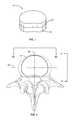
- FIG. 2is a top view of a vertebral implant according to one embodiment shown relative to a vertebral body;
- FIG. 3is an anterior view of a vertebral implant illustrating a set of different coronal angle implants according to one embodiment
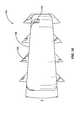
- FIG. 4is a lateral view of a vertebral implant illustrating a set of different sagittal angle implants according to one embodiment
- FIG. 5is a perspective view of a vertebral implant according to one embodiment
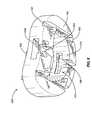
- FIG. 6is a perspective view depicting an exploded assembly of a vertebral implant according to one embodiment
- FIG. 7is an anterior view of a coronal angle implant according to one embodiment
- FIG. 8is a perspective view of a coronal angle implant according to one embodiment
- FIG. 9is a perspective view of a coronal angle implant according to one embodiment.
- FIG. 10is a lateral view of a sagittal angle implant according to one embodiment
- FIG. 11is a perspective view of a sagittal angle implant according to one embodiment
- FIG. 12is a perspective view of a sagittal angle implant according to one embodiment
- FIG. 13is a top view of a vertebral implant according to one embodiment shown relative to a vertebral body;
- FIG. 14is a top view of a vertebral implant according to one embodiment shown relative to a vertebral body;
- FIG. 15is a perspective view of a vertebral implant according to one embodiment
- FIG. 16is an anterior view of a vertebral implant according to one embodiment.
- FIG. 17is a lateral view of a vertebral implant according to one embodiment.
- Reference number 10 in FIG. 1generally identifies one example of an implant with a coronal angle implant 20 in a stacked configuration with a sagittal angle implant 30 .
- the representative vertebral implant 10is illustrated as a disc replacement implant that is inserted between vertebral bodies of a patient as part of a disc replacement surgery.
- the vertebral implant 10may include a height sufficient to replace one or more vertebral levels as part of a vertebrectomy or corpectomy surgery.
- the vertebral implant 10is illustrated with the coronal angle implant 20 disposed superior to the sagittal angle implant 30 , though it should be understood that the opposite relationship may be used as desired.
- the vertebral implant 10including the coronal angle implant 20 and sagittal angle implant 30 may be constructed from biocompatible metal alloys such as titanium, cobalt-chrome, and stainless steel.
- the vertebral implant 10may be constructed from non-metallic materials, including for example, ceramics, resins, or polymers, such as UHMWPE and implantable grade polyetheretherketone (PEEK) or other similar materials (e.g., PAEK, PEKK, and PEK).
- PEEKimplantable grade polyetheretherketone
- the vertebral implant 10may be constructed of synthetic or natural bone or bone composites.
- the coronal angle implant 20 and sagittal angle implant 30may be constructed of the same or different materials.
- the coronal angle implant 20may include a different modulus of elasticity than the sagittal angle implant 30 to provide more or less resistance to motion in a given plane.
- coronal angle implant 20 and the sagittal angle implant 30may include the same or different heights.
- FIG. 2illustrates the vertebral implant 10 in position relative to a dashed line representation of a vertebral body V.
- FIG. 2also illustrates a sagittal reference plane SP and a coronal reference plane CP.
- the sagittal plane SPis the imaginary anatomical plane that bilaterally separates the body into left and right halves.
- the coronal plane CPis the imaginary anatomical plane that separates the body into anterior and posterior regions.
- FIGS. 3 and 4illustrate anterior and lateral views of the exemplary vertebral implant 10 according to the view lines shown in FIG. 2 . Specifically, FIG. 3 is shown from a direction substantially normal to the coronal plane while FIG. 4 is shown from a direction substantially normal to the sagittal plane.
- FIGS. 3 and 4show that the coronal angle implant 20 and the sagittal angle implant 30 are substantially tapered or wedge-shaped in a particular direction.
- FIG. 3depicts a coronal angle a associated with the coronal angle implant 20 .
- the sagittal angle implant 30does not include any significant angle or tilt in the coronal plane.
- selecting an appropriate coronal angle implant 20independent of the selected sagittal angle implant 30 , may provide a desired coronal angle correction ⁇ .
- FIG. 3also shows various alternative coronal angle implants 20 a - c that may be used in lieu of coronal angle implant 20 if different coronal angles, ⁇ 1 , ⁇ 2 , or ⁇ 3 are desired.
- the coronal angle implants 20 , 20 a - cmay form part of a set 22 of coronal angle implants that comprises individual implants that include different coronal angles.
- the set 22may include individual implants that include different heights as well.
- the set 22may include a plurality of different implants, each including a different coronal angle ⁇ varying from about ⁇ 20 degrees to about +20 degrees.
- each coronal angle implant 20 , 20 a - cmay include a designator 24 to distinguish the individual implant 20 , 20 a - c from others in the set 22 .
- the designator 24may include a graphical marking indicating the coronal angle in degrees.
- the designator 24may include an alphanumeric identifier representing one of a sequence of characters. In one embodiment, the designator 24 may include a color code. In each case, the designator 24 may be engraved, etched, printed, marked, adhered, or otherwise displayed on the coronal angle implant 20 , 20 a - c or on packaging associated with the implant. Other possible designators 24 may be used as well.
- FIG. 4depicts a sagittal angle ⁇ associated with the sagittal angle implant 30 .
- the coronal angle implant 20does not include any significant angle or tilt in the sagittal plane.
- selecting an appropriate sagittal angle implant 30independent of the selected coronal angle implant 20 , may provide a desired sagittal angle ⁇ .
- FIG. 4shows various alternative sagittal angle implants 30 a - c that may be used in lieu of sagittal angle implant 30 if different sagittal angles, ⁇ 1 , ⁇ 2 , or ⁇ 3 are desired.
- the sagittal angle implants 30 , 30 a - cmay form part of a set 32 of sagittal angle implants that includes individual implants with different sagittal angles ⁇ .
- the set 32may include individual implants that include different heights as well.
- the set 32may include a plurality of different implants, each including a different sagittal angle ⁇ varying from about ⁇ 40 degrees to about +40 degrees.
- each sagittal angle implant 30 , 30 a - cmay include a designator 34 to distinguish the individual implant 30 , 30 a - c from others in the set 32 as described above.
- FIG. 5depicts one embodiment of a vertebral implant 110 incorporating a coronal angle implant 120 and a sagittal angle implant 130 as described above.
- the embodiment shown in FIG. 5also includes a connector 140 that holds the coronal angle implant 120 and the sagittal angle implant 130 together.
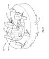
- FIG. 6illustrates an exploded view of the vertebral implant 110 and more clearly shows various features of the coronal angle implant 120 and the sagittal angle implant 130 .
- the illustrated connector 140includes an I-beam cross section and is sized to fit within a similarly shaped recess 142 that is formed in the coronal angle implant 120 and the sagittal angle implant 130 .
- One portion 142 a of the recess 142is formed in the coronal angle implant 120 while the other portion 142 b of the recess 142 is formed in the sagittal angle implant 130 .
- the recess 142is symmetrically distributed within the coronal angle implant 120 and the sagittal angle implant 130 .
- a majority of the recessis disposed in one or the other of the coronal angle implant 120 and the sagittal angle implant 130 .
- the connector 140includes enlarged portions 144 , 148 disposed on opposite ends of a narrow intermediate portion 146 .
- the enlarged end portions 144 , 148are inserted into the corresponding portions 142 a , 142 b of the recess 142 , contact between undercut surfaces 150 , 152 and the enlarged end portions 144 , 148 prevents the coronal angle implant 120 and the sagittal angle implant 130 from separating.
- the connector 140may include shapes such as an hourglass or a dumbbell.
- the connector 140may include other cross section shapes, including a C-shape, and S-shape, an X-shape, or other shape that sufficiently prevents separation of the coronal angle implant 120 and the sagittal angle implant 130 .
- retainer clipssuch as a C-clip, U-clip, or retainer ring may be used to hold the coronal angle implant 120 and sagittal angle implant 130 together.
- the coronal angle implant 120 and the sagittal angle implant 130also include retainers 154 that secure the connector 140 within the recess 142 in the coronal angle implant 120 and the sagittal angle implant 130 .
- the retainers 154are implemented as pairs inwardly biased fingers that are spaced apart a distance that is less than the width of the intermediate portion 146 of the connector. The retainers 154 may be deflected away from each other to allow the connector 140 to fit into the recess 142 . Once the connector 140 is inserted completely within the recess 142 , the retainers 154 deflect to their normal position within a recess 156 in the connector 140 .
- the vertebral implant 110includes a total of four retainers 154 , with two each in the coronal angle implant 120 and the sagittal angle implant 130 .
- the coronal angle implant 120 and the sagittal angle implant 130each include a single retainer 154 .
- a flexible retainer 154may be disposed on the connector 140 and configured to engage a corresponding recess in the coronal angle implant 120 and the sagittal angle implant 130 .
- a flexible retainer 154may be disposed on the connector 140 and configured to engage a corresponding recess in the coronal angle implant 120 and the sagittal angle implant 130 .
- the coronal angle implant 120 and the sagittal angle implant 130also include a plurality of bone engagement features 160 disposed about the superior and inferior surfaces of each implant 120 , 130 .
- these bone engagement features 160are depicted as ramped teeth, though it should be understood that other types of features might be used.
- the bone engagement features 160may be implemented as pyramid shaped, diamond shaped, cone shaped, or other protruding feature adapted to engage, embed, scour, scrape, or decorticate the end plates of a vertebral body.
- the coronal angle implant 120 and the sagittal angle implant 130each include a plurality of recesses 162 disposed at the surface that contacts the other implant.
- the coronal angle implant 120includes these recesses 162 at the inferior surface 164 .
- the sagittal angle implant 130includes recesses 162 at the superior surface 166 .
- the recesses 162may be disposed at the opposite surface (i.e., the surface that is positioned in contact with the other implant 120 , 130 ).
- the recesses 162are disposed on both superior and inferior surfaces of the implant 120 , 130 .
- the recesses 162 on the coronal angle implant 120are substantially aligned with the bone engagement features 160 of the sagittal angle implant 130 .
- the recesses 162 on the sagittal angle implant 130are substantially aligned with the bone engagement features 160 of the coronal angle implant 120 .
- the coronal angle implant 120 and the sagittal angle implant 130are able to be positioned with the inferior surface 164 of the coronal angle implant 120 in contact with the superior surface 166 of the sagittal angle implant 130 .
- each implant 120 , 130may be surgically installed without the other.
- a coronal angle implant 120 that includes the appropriate coronal angle ⁇may be inserted between vertebral bodies in the appropriate region of the spine.
- a sagittal angle implant 130 with the appropriate sagittal angle ⁇may be inserted between vertebral bodies in the appropriate region of the spine.
- a coronal angle implant 120 with an appropriate coronal angle ⁇ and a sagittal angle implant 130 with an appropriate sagittal angle ⁇may be used together and inserted between vertebral bodies in the appropriate region of the spine. Accordingly, each of the coronal angle implant 120 and the sagittal angle implant 130 may be used either in conjunction with the other implant, or by itself.
- FIGS. 7 , 8 , and 9depict various views of the exemplary coronal angle implant 120 .
- FIG. 7shows a posterior view of the coronal angle implant 120 and illustrates the coronal angle ⁇ .
- FIG. 8shows a perspective view of the coronal angle implant 120 depicted from inferior and posterior directions. The inferior surface 164 of the coronal angle implant 120 is more clearly visible in FIG. 8 .
- FIG. 8shows that the coronal angle implant 120 includes an inner wall 170 that defines an inner cavity 172 .
- the recess 142 a for connector 140extends across the cavity 172 but ends at a stop surface 168 . That is, the recess 142 a does not extend all the way through the coronal angle implant 120 .
- an inserted connector 140is constrained within the recess 142 a by the stop surface 168 and the retainers 154 .
- FIG. 9shows a perspective view of the coronal angle implant 120 depicted from superior and anterior directions.
- the inner wall 170 and inner cavity 172are clearly visible in this particular view.
- FIG. 12shows that a similar cavity 182 exists in the sagittal angle implant 130 .
- the connector 140is exposed within these cavities 172 , 182 .
- the connector 140may be constructed with a bone growth promoting material such as BMP, DBM, hydroxyapatite, allograft, autograft or other osteoinductive growth factors to facilitate fusion between vertebral bodies and the implant 10 .
- These and other types of bone growth promoting materialsmay be packed into the cavities 172 , 182 around the connector 140 to further promote fusion between the implant 110 and vertebral bodies.
- FIGS. 10 , 11 , and 12depict various views of the exemplary sagittal angle implant 130 .
- FIG. 10shows a lateral view of the sagittal angle implant 130 and illustrates the sagittal angle ⁇ .
- FIG. 11shows a perspective view of the sagittal angle implant 130 depicted from superior and posterior directions.
- FIG. 11shows that the sagittal angle implant 130 includes an inner wall 180 that defines an inner cavity 182 similar to the cavity 172 in the coronal angle implant 120 .
- FIG. 11shows that the recess 142 b for connector 140 extends across the cavity 182 but ends at a stop surface 174 . That is, the recess 142 a does not extend all the way through the sagittal angle implant 130 .
- FIG. 12shows a perspective view of the sagittal angle implant 130 depicted from inferior and anterior directions. The inner wall 180 and inner cavity 182 are clearly visible in this particular view.
- the vertebral implants 10 , 110 , 120 , 130 disclosed abovegenerally include a kidney shape, though other shapes and contours may be used.
- the vertebral implantmay take on other types of configurations, such as, for example, a circular shape, semi-oval shape, bean-shape, D-shape, elliptical-shape, egg-shape, or any other shape that would occur to one of skill in the art.
- the vertebral implantcould also be described as being annular, U-shaped, C-shaped, V-shaped, horseshoe-shaped, semi-circular shaped, semi-oval shaped, or other similar terms defining an implant including at least a partially open or hollow construction. For example, FIG.
- FIG. 13shows one embodiment of a vertebral implant 210 that includes a horseshoe configuration.
- the implant 210may be implanted from an anterior, lateral, or posterior approach.
- the vertebral implantmay take on substantially solid configurations, such as, for example, block-like or plate-like configurations that do not define an open inner region.
- the embodiments shown in FIGS. 1-4provide one example of a substantially solid configuration.
- Other embodimentsmay include an annular configuration similar to the embodiments illustrated in FIGS. 5-12 .
- Other embodimentsmay include multiple, unattached portions, such as TLIF or PLIF cages or the exemplary implant 310 shown in FIG. 14 .
- FIGS. 15 , 16 , and 17show an embodiment 510 of a vertebral implant that includes a spacer 540 that serves at least two purposes.
- the spacer 540includes enlarged portions 542 to retain the coronal angle implant 520 and the sagittal angle implant 530 .
- the spacer 540is similar to the connector 140 in this regard.
- the spacer 540adds additional height H to the vertebral implant 510 that may be necessary for vertebrectomy and corpectomy procedures.
- the coronal angle implant 520includes an associated coronal angle ⁇ for spinal correction in the coronal plane.
- the sagittal angle implant 530includes an associated sagittal angle ⁇ for spinal correction in the sagittal plane.
- the coronal angle implant 520is shown in a superior position relative to the spacer 540 and sagittal angle implant 530 .
- the sagittal angle implant 530may be disposed superior to the spacer 540 and coronal angle implant 520 .
- Embodiments disclosed abovehave not included any particular surface geometry, coating, or porosity as are found in conventionally known vertebral implants.
- Surface featuressuch as these are used to promote bone growth and adhesion at the interface between an implant and a vertebral body. Examples of features used for this purpose include, for example, teeth, scales, keels, knurls, and roughened surfaces. Some of these features may be applied through post-processing techniques such as blasting, chemical etching, and coating, such as with hydroxyapatite.
- the superior and inferior bone interface surfaces of the vertebral implantmay also include growth-promoting additives such as bone morphogenetic proteins. Alternatively, pores, cavities, or other recesses into which bone may grow may be incorporated via a molding process. Other types of coatings or surface preparation may be used to improve bone growth into or through the bone-contact surfaces.
- the present inventionmay be carried out in other specific ways than those herein set forth without departing from the scope and essential characteristics of the invention.
- the geometries described hereinmay be implemented in ALIF, PLIF, or TLIF cages with an interior cavity for inserting bone growth promoting materials.
- the present embodimentsare, therefore, to be considered in all respects as illustrative and not restrictive, and all changes coming within the meaning and equivalency range of the appended claims are intended to be embraced therein.
Landscapes
- Health & Medical Sciences (AREA)
- Engineering & Computer Science (AREA)
- Biomedical Technology (AREA)
- Orthopedic Medicine & Surgery (AREA)
- Neurology (AREA)
- Heart & Thoracic Surgery (AREA)
- Oral & Maxillofacial Surgery (AREA)
- Transplantation (AREA)
- Cardiology (AREA)
- Vascular Medicine (AREA)
- Life Sciences & Earth Sciences (AREA)
- Animal Behavior & Ethology (AREA)
- General Health & Medical Sciences (AREA)
- Public Health (AREA)
- Veterinary Medicine (AREA)
- Prostheses (AREA)
Abstract
Description
Claims (10)
Priority Applications (2)
| Application Number | Priority Date | Filing Date | Title |
|---|---|---|---|
| US11/403,351US8366776B2 (en) | 2006-04-13 | 2006-04-13 | Vertebral implants having predetermined angular correction and method of use |
| PCT/US2007/065960WO2007121095A1 (en) | 2006-04-13 | 2007-04-04 | Non-locking multi-axial joints in a vertebral implants |
Applications Claiming Priority (1)
| Application Number | Priority Date | Filing Date | Title |
|---|---|---|---|
| US11/403,351US8366776B2 (en) | 2006-04-13 | 2006-04-13 | Vertebral implants having predetermined angular correction and method of use |
Publications (2)
| Publication Number | Publication Date |
|---|---|
| US20070270957A1 US20070270957A1 (en) | 2007-11-22 |
| US8366776B2true US8366776B2 (en) | 2013-02-05 |
Family
ID=38461084
Family Applications (1)
| Application Number | Title | Priority Date | Filing Date |
|---|---|---|---|
| US11/403,351Active2029-01-23US8366776B2 (en) | 2006-04-13 | 2006-04-13 | Vertebral implants having predetermined angular correction and method of use |
Country Status (1)
| Country | Link |
|---|---|
| US (1) | US8366776B2 (en) |
Cited By (18)
| Publication number | Priority date | Publication date | Assignee | Title |
|---|---|---|---|---|
| US20140296984A1 (en)* | 2013-04-01 | 2014-10-02 | Mohammad Etminan | Cage system |
| USD720457S1 (en)* | 2012-07-26 | 2014-12-30 | Paragon 28, Inc. | Calcaneo-cuboid bone wedge |
| USD720456S1 (en)* | 2012-07-26 | 2014-12-30 | Paragon 28, Inc. | Lapidus bone wedge |
| US9149365B2 (en) | 2013-03-05 | 2015-10-06 | Globus Medical, Inc. | Low profile plate |
| US9237957B2 (en) | 2011-09-16 | 2016-01-19 | Globus Medical, Inc. | Low profile plate |
| US9539109B2 (en) | 2011-09-16 | 2017-01-10 | Globus Medical, Inc. | Low profile plate |
| USD782151S1 (en)* | 2015-01-21 | 2017-03-28 | Hill's Pet Nutrition, Inc. | Pet food piece |
| US9681959B2 (en) | 2011-09-16 | 2017-06-20 | Globus Medical, Inc. | Low profile plate |
| US9700425B1 (en) | 2011-03-20 | 2017-07-11 | Nuvasive, Inc. | Vertebral body replacement and insertion methods |
| US9848994B2 (en) | 2011-09-16 | 2017-12-26 | Globus Medical, Inc. | Low profile plate |
| US9907669B2 (en)* | 2014-08-22 | 2018-03-06 | Globus Medical, Inc. | Vertebral implants and related methods of use |
| USD838124S1 (en)* | 2017-10-05 | 2019-01-15 | Somnox Holding B.V. | Pillow |
| US10245155B2 (en) | 2011-09-16 | 2019-04-02 | Globus Medical, Inc. | Low profile plate |
| US10271960B2 (en) | 2017-04-05 | 2019-04-30 | Globus Medical, Inc. | Decoupled spacer and plate and method of installing the same |
| US10376385B2 (en) | 2017-04-05 | 2019-08-13 | Globus Medical, Inc. | Decoupled spacer and plate and method of installing the same |
| US10893951B2 (en) | 2018-08-07 | 2021-01-19 | Minimally Invasive Spinal Technology, LLC | Device and method for correcting spinal deformities in patients |
| US11717417B2 (en) | 2011-09-16 | 2023-08-08 | Globus Medical Inc. | Low profile plate |
| USD1062145S1 (en)* | 2022-05-23 | 2025-02-18 | Ferrara Candy Company | Confection |
Families Citing this family (65)
| Publication number | Priority date | Publication date | Assignee | Title |
|---|---|---|---|---|
| AU2004212942A1 (en) | 2003-02-14 | 2004-09-02 | Depuy Spine, Inc. | In-situ formed intervertebral fusion device |
| US8366773B2 (en) | 2005-08-16 | 2013-02-05 | Benvenue Medical, Inc. | Apparatus and method for treating bone |
| AU2006279558B2 (en) | 2005-08-16 | 2012-05-17 | Izi Medical Products, Llc | Spinal tissue distraction devices |
| WO2008103781A2 (en) | 2007-02-21 | 2008-08-28 | Benvenue Medical, Inc. | Devices for treating the spine |
| US8092533B2 (en)* | 2006-10-03 | 2012-01-10 | Warsaw Orthopedic, Inc. | Dynamic devices and methods for stabilizing vertebral members |
| US9023107B2 (en)* | 2006-11-08 | 2015-05-05 | Spinal Usa, Inc. | Vertebral body replacement |
| US8920502B1 (en)* | 2006-11-08 | 2014-12-30 | Spinal Usa, Inc. | Vertebral body replacement |
| WO2008070863A2 (en) | 2006-12-07 | 2008-06-12 | Interventional Spine, Inc. | Intervertebral implant |
| US9039768B2 (en) | 2006-12-22 | 2015-05-26 | Medos International Sarl | Composite vertebral spacers and instrument |
| EP2124778B1 (en) | 2007-02-21 | 2019-09-25 | Benvenue Medical, Inc. | Devices for treating the spine |
| US8900307B2 (en) | 2007-06-26 | 2014-12-02 | DePuy Synthes Products, LLC | Highly lordosed fusion cage |
| EP2237748B1 (en) | 2008-01-17 | 2012-09-05 | Synthes GmbH | An expandable intervertebral implant |
| US20090248092A1 (en) | 2008-03-26 | 2009-10-01 | Jonathan Bellas | Posterior Intervertebral Disc Inserter and Expansion Techniques |
| US8936641B2 (en) | 2008-04-05 | 2015-01-20 | DePuy Synthes Products, LLC | Expandable intervertebral implant |
| US8535327B2 (en) | 2009-03-17 | 2013-09-17 | Benvenue Medical, Inc. | Delivery apparatus for use with implantable medical devices |
| US9526620B2 (en)* | 2009-03-30 | 2016-12-27 | DePuy Synthes Products, Inc. | Zero profile spinal fusion cage |
| US9028553B2 (en) | 2009-11-05 | 2015-05-12 | DePuy Synthes Products, Inc. | Self-pivoting spinal implant and associated instrumentation |
| US9393129B2 (en) | 2009-12-10 | 2016-07-19 | DePuy Synthes Products, Inc. | Bellows-like expandable interbody fusion cage |
| US9907560B2 (en) | 2010-06-24 | 2018-03-06 | DePuy Synthes Products, Inc. | Flexible vertebral body shavers |
| US8979860B2 (en) | 2010-06-24 | 2015-03-17 | DePuy Synthes Products. LLC | Enhanced cage insertion device |
| US8623091B2 (en) | 2010-06-29 | 2014-01-07 | DePuy Synthes Products, LLC | Distractible intervertebral implant |
| US20120078373A1 (en) | 2010-09-23 | 2012-03-29 | Thomas Gamache | Stand alone intervertebral fusion device |
| US11529241B2 (en) | 2010-09-23 | 2022-12-20 | DePuy Synthes Products, Inc. | Fusion cage with in-line single piece fixation |
| US20120078372A1 (en) | 2010-09-23 | 2012-03-29 | Thomas Gamache | Novel implant inserter having a laterally-extending dovetail engagement feature |
| US9402732B2 (en) | 2010-10-11 | 2016-08-02 | DePuy Synthes Products, Inc. | Expandable interspinous process spacer implant |
| EP3485851B1 (en) | 2011-03-22 | 2021-08-25 | DePuy Synthes Products, LLC | Universal trial for lateral cages |
| US8814873B2 (en) | 2011-06-24 | 2014-08-26 | Benvenue Medical, Inc. | Devices and methods for treating bone tissue |
| US8961606B2 (en)* | 2011-09-16 | 2015-02-24 | Globus Medical, Inc. | Multi-piece intervertebral implants |
| US9398960B2 (en) | 2011-09-16 | 2016-07-26 | Globus Medical, Inc. | Multi-piece intervertebral implants |
| US9204975B2 (en) | 2011-09-16 | 2015-12-08 | Globus Medical, Inc. | Multi-piece intervertebral implants |
| US9248028B2 (en) | 2011-09-16 | 2016-02-02 | DePuy Synthes Products, Inc. | Removable, bone-securing cover plate for intervertebral fusion cage |
| US9271836B2 (en) | 2012-03-06 | 2016-03-01 | DePuy Synthes Products, Inc. | Nubbed plate |
| US9226764B2 (en) | 2012-03-06 | 2016-01-05 | DePuy Synthes Products, Inc. | Conformable soft tissue removal instruments |
| US10182921B2 (en) | 2012-11-09 | 2019-01-22 | DePuy Synthes Products, Inc. | Interbody device with opening to allow packing graft and other biologics |
| US10022245B2 (en) | 2012-12-17 | 2018-07-17 | DePuy Synthes Products, Inc. | Polyaxial articulating instrument |
| US20140207235A1 (en)* | 2013-01-23 | 2014-07-24 | Warsaw Orthopedic, Inc. | Expandable allograft cage |
| US9717601B2 (en) | 2013-02-28 | 2017-08-01 | DePuy Synthes Products, Inc. | Expandable intervertebral implant, system, kit and method |
| US9522070B2 (en) | 2013-03-07 | 2016-12-20 | Interventional Spine, Inc. | Intervertebral implant |
| US10085783B2 (en) | 2013-03-14 | 2018-10-02 | Izi Medical Products, Llc | Devices and methods for treating bone tissue |
| US11426290B2 (en) | 2015-03-06 | 2022-08-30 | DePuy Synthes Products, Inc. | Expandable intervertebral implant, system, kit and method |
| JP5854361B1 (en)* | 2015-03-08 | 2016-02-09 | 株式会社カタリメディック | Artificial bone spacer |
| CA3014916A1 (en) | 2016-02-18 | 2017-08-24 | Lifenet Health | Bone graft and method of making and using same |
| US10856992B2 (en)* | 2016-04-27 | 2020-12-08 | AOD Holdings, LLC | Implant device(s) including tapered protrusions and method(s) for inserting the same into bone |
| US11510788B2 (en) | 2016-06-28 | 2022-11-29 | Eit Emerging Implant Technologies Gmbh | Expandable, angularly adjustable intervertebral cages |
| EP3474784A2 (en) | 2016-06-28 | 2019-05-01 | Eit Emerging Implant Technologies GmbH | Expandable and angularly adjustable intervertebral cages with articulating joint |
| US10278834B2 (en)* | 2016-09-14 | 2019-05-07 | Globus Medical, Inc. | Center lordotic mesh cage |
| US10278833B2 (en)* | 2016-09-14 | 2019-05-07 | Globus Medical, Inc. | Center lordotic mesh cage |
| US10888433B2 (en) | 2016-12-14 | 2021-01-12 | DePuy Synthes Products, Inc. | Intervertebral implant inserter and related methods |
| US10398563B2 (en) | 2017-05-08 | 2019-09-03 | Medos International Sarl | Expandable cage |
| US11344424B2 (en) | 2017-06-14 | 2022-05-31 | Medos International Sarl | Expandable intervertebral implant and related methods |
| US10940016B2 (en) | 2017-07-05 | 2021-03-09 | Medos International Sarl | Expandable intervertebral fusion cage |
| US10966843B2 (en) | 2017-07-18 | 2021-04-06 | DePuy Synthes Products, Inc. | Implant inserters and related methods |
| US11045331B2 (en) | 2017-08-14 | 2021-06-29 | DePuy Synthes Products, Inc. | Intervertebral implant inserters and related methods |
| US11446156B2 (en) | 2018-10-25 | 2022-09-20 | Medos International Sarl | Expandable intervertebral implant, inserter instrument, and related methods |
| US20230038323A1 (en)* | 2018-11-19 | 2023-02-09 | Axis Spine Technologies Ltd | Intervertebral devices |
| GB201818850D0 (en)* | 2018-11-19 | 2019-01-02 | Axis Spine Tech Ltd | Intervertebral devices |
| GB201818847D0 (en)* | 2018-11-19 | 2019-01-02 | Axis Spine Tech Ltd | Intervertebral devices |
| GB201818849D0 (en)* | 2018-11-19 | 2019-01-02 | Axis Spine Tech Ltd | Intervertebral devices |
| GB201902002D0 (en) | 2019-02-13 | 2019-04-03 | Axis Spine Tech Ltd | Intervertebral devices |
| GB201910668D0 (en) | 2019-07-25 | 2019-09-11 | Axis Spine Tech Ltd | Assemblies for and methods of determing height and angle of an intervertebral device |
| GB201910640D0 (en) | 2019-07-25 | 2019-09-11 | Axis Spine Tech Ltd | Insertions instruments |
| US11426286B2 (en) | 2020-03-06 | 2022-08-30 | Eit Emerging Implant Technologies Gmbh | Expandable intervertebral implant |
| US11850160B2 (en) | 2021-03-26 | 2023-12-26 | Medos International Sarl | Expandable lordotic intervertebral fusion cage |
| US11752009B2 (en) | 2021-04-06 | 2023-09-12 | Medos International Sarl | Expandable intervertebral fusion cage |
| US12090064B2 (en) | 2022-03-01 | 2024-09-17 | Medos International Sarl | Stabilization members for expandable intervertebral implants, and related systems and methods |
Citations (31)
| Publication number | Priority date | Publication date | Assignee | Title |
|---|---|---|---|---|
| US4304011A (en) | 1980-08-25 | 1981-12-08 | Whelan Iii Edward J | Semi-constrained metacarpophalangeal prosthesis |
| US4997432A (en) | 1988-03-23 | 1991-03-05 | Waldemar Link Gmbh & Co. | Surgical instrument set |
| US5192327A (en)* | 1991-03-22 | 1993-03-09 | Brantigan John W | Surgical prosthetic implant for vertebrae |
| US5609637A (en) | 1993-07-09 | 1997-03-11 | Biedermann; Lutz | Space keeper, in particular for an intervertebral disk |
| US6106557A (en) | 1998-07-23 | 2000-08-22 | Howmedica Gmbh | Reconstruction system for vertebra |
| US6146421A (en) | 1997-08-04 | 2000-11-14 | Gordon, Maya, Roberts And Thomas, Number 1, Llc | Multiple axis intervertebral prosthesis |
| US6159211A (en)* | 1998-10-22 | 2000-12-12 | Depuy Acromed, Inc. | Stackable cage system for corpectomy/vertebrectomy |
| US20020082701A1 (en)* | 1999-06-04 | 2002-06-27 | Zdeblick Thomas A. | Artificial disc implant |
| US6432106B1 (en) | 1999-11-24 | 2002-08-13 | Depuy Acromed, Inc. | Anterior lumbar interbody fusion cage with locking plate |
| US6447548B1 (en) | 2001-07-16 | 2002-09-10 | Third Millennium Engineering, Llc | Method of surgically treating scoliosis |
| US6468311B2 (en) | 2001-01-22 | 2002-10-22 | Sdgi Holdings, Inc. | Modular interbody fusion implant |
| US6554863B2 (en) | 1998-08-03 | 2003-04-29 | Synthes | Intervertebral allograft spacer |
| US20030191531A1 (en)* | 2002-03-21 | 2003-10-09 | Berry Bret M. | Vertebral body and disc space replacement devices |
| US20030199980A1 (en)* | 2002-04-23 | 2003-10-23 | Uwe Siedler | Vertebral column implant |
| US6676703B2 (en) | 1999-02-25 | 2004-01-13 | Depuy Acromed, Inc. | Spinal fusion implant |
| US6682564B1 (en) | 2002-07-02 | 2004-01-27 | Luis Duarte | Intervertebral support device and related methods |
| US20040049272A1 (en) | 1999-10-22 | 2004-03-11 | Archus Orthopedics, Inc. | Facet arthroplasty devices and methods |
| US6719794B2 (en)* | 2001-05-03 | 2004-04-13 | Synthes (U.S.A.) | Intervertebral implant for transforaminal posterior lumbar interbody fusion procedure |
| US20040122518A1 (en) | 2002-12-19 | 2004-06-24 | Rhoda William S. | Intervertebral implant |
| US20040133279A1 (en) | 2003-01-06 | 2004-07-08 | Krueger David J. | Surgical implants for use as spinal spacers |
| US20040176843A1 (en)* | 2003-03-06 | 2004-09-09 | Rafail Zubok | Instrumentation and methods for use in implanting a cervical disc replacement device |
| US6830589B2 (en) | 1999-06-23 | 2004-12-14 | Zimmer Spine, Inc. | Expandable fusion device and method |
| US20050187632A1 (en)* | 2004-02-20 | 2005-08-25 | Rafail Zubok | Artificial intervertebral disc having a bored semispherical bearing with a compression locking post and retaining caps |
| US20050277919A1 (en) | 2004-05-28 | 2005-12-15 | Depuy Spine, Inc. | Anchoring systems and methods for correcting spinal deformities |
| US20060009850A1 (en)* | 2002-12-17 | 2006-01-12 | Mathys Medizinaltechnik Ag | Intervertebral implant |
| US20060015184A1 (en) | 2004-01-30 | 2006-01-19 | John Winterbottom | Stacking implants for spinal fusion |
| US20060190082A1 (en)* | 2002-03-12 | 2006-08-24 | Cervitech, Inc. | Intervertebral prosthesis system, in particular for the cervical spine |
| US20060212118A1 (en)* | 2005-03-16 | 2006-09-21 | Abernathie Dennis L | Spinal fusion cage and method of use |
| WO2007087562A1 (en) | 2006-01-27 | 2007-08-02 | Warsaw Orthopedic, Inc. | Non-locking multi-axial joints in a vertebral implant and methods of use |
| US20080133013A1 (en)* | 2004-06-30 | 2008-06-05 | Synergy Disc Replacement, Inc. | Artificial Spinal Disc |
| US7704280B2 (en)* | 2003-07-22 | 2010-04-27 | Synthes Usa, Llc | Intervertebral implant comprising temporary blocking means |
- 2006
- 2006-04-13USUS11/403,351patent/US8366776B2/enactiveActive
Patent Citations (31)
| Publication number | Priority date | Publication date | Assignee | Title |
|---|---|---|---|---|
| US4304011A (en) | 1980-08-25 | 1981-12-08 | Whelan Iii Edward J | Semi-constrained metacarpophalangeal prosthesis |
| US4997432A (en) | 1988-03-23 | 1991-03-05 | Waldemar Link Gmbh & Co. | Surgical instrument set |
| US5192327A (en)* | 1991-03-22 | 1993-03-09 | Brantigan John W | Surgical prosthetic implant for vertebrae |
| US5609637A (en) | 1993-07-09 | 1997-03-11 | Biedermann; Lutz | Space keeper, in particular for an intervertebral disk |
| US6146421A (en) | 1997-08-04 | 2000-11-14 | Gordon, Maya, Roberts And Thomas, Number 1, Llc | Multiple axis intervertebral prosthesis |
| US6106557A (en) | 1998-07-23 | 2000-08-22 | Howmedica Gmbh | Reconstruction system for vertebra |
| US6554863B2 (en) | 1998-08-03 | 2003-04-29 | Synthes | Intervertebral allograft spacer |
| US6159211A (en)* | 1998-10-22 | 2000-12-12 | Depuy Acromed, Inc. | Stackable cage system for corpectomy/vertebrectomy |
| US6676703B2 (en) | 1999-02-25 | 2004-01-13 | Depuy Acromed, Inc. | Spinal fusion implant |
| US20020082701A1 (en)* | 1999-06-04 | 2002-06-27 | Zdeblick Thomas A. | Artificial disc implant |
| US6830589B2 (en) | 1999-06-23 | 2004-12-14 | Zimmer Spine, Inc. | Expandable fusion device and method |
| US20040049272A1 (en) | 1999-10-22 | 2004-03-11 | Archus Orthopedics, Inc. | Facet arthroplasty devices and methods |
| US6432106B1 (en) | 1999-11-24 | 2002-08-13 | Depuy Acromed, Inc. | Anterior lumbar interbody fusion cage with locking plate |
| US6468311B2 (en) | 2001-01-22 | 2002-10-22 | Sdgi Holdings, Inc. | Modular interbody fusion implant |
| US6719794B2 (en)* | 2001-05-03 | 2004-04-13 | Synthes (U.S.A.) | Intervertebral implant for transforaminal posterior lumbar interbody fusion procedure |
| US6447548B1 (en) | 2001-07-16 | 2002-09-10 | Third Millennium Engineering, Llc | Method of surgically treating scoliosis |
| US20060190082A1 (en)* | 2002-03-12 | 2006-08-24 | Cervitech, Inc. | Intervertebral prosthesis system, in particular for the cervical spine |
| US20030191531A1 (en)* | 2002-03-21 | 2003-10-09 | Berry Bret M. | Vertebral body and disc space replacement devices |
| US20030199980A1 (en)* | 2002-04-23 | 2003-10-23 | Uwe Siedler | Vertebral column implant |
| US6682564B1 (en) | 2002-07-02 | 2004-01-27 | Luis Duarte | Intervertebral support device and related methods |
| US20060009850A1 (en)* | 2002-12-17 | 2006-01-12 | Mathys Medizinaltechnik Ag | Intervertebral implant |
| US20040122518A1 (en) | 2002-12-19 | 2004-06-24 | Rhoda William S. | Intervertebral implant |
| US20040133279A1 (en) | 2003-01-06 | 2004-07-08 | Krueger David J. | Surgical implants for use as spinal spacers |
| US20040176843A1 (en)* | 2003-03-06 | 2004-09-09 | Rafail Zubok | Instrumentation and methods for use in implanting a cervical disc replacement device |
| US7704280B2 (en)* | 2003-07-22 | 2010-04-27 | Synthes Usa, Llc | Intervertebral implant comprising temporary blocking means |
| US20060015184A1 (en) | 2004-01-30 | 2006-01-19 | John Winterbottom | Stacking implants for spinal fusion |
| US20050187632A1 (en)* | 2004-02-20 | 2005-08-25 | Rafail Zubok | Artificial intervertebral disc having a bored semispherical bearing with a compression locking post and retaining caps |
| US20050277919A1 (en) | 2004-05-28 | 2005-12-15 | Depuy Spine, Inc. | Anchoring systems and methods for correcting spinal deformities |
| US20080133013A1 (en)* | 2004-06-30 | 2008-06-05 | Synergy Disc Replacement, Inc. | Artificial Spinal Disc |
| US20060212118A1 (en)* | 2005-03-16 | 2006-09-21 | Abernathie Dennis L | Spinal fusion cage and method of use |
| WO2007087562A1 (en) | 2006-01-27 | 2007-08-02 | Warsaw Orthopedic, Inc. | Non-locking multi-axial joints in a vertebral implant and methods of use |
Non-Patent Citations (1)
| Title |
|---|
| "International Search Report," International Application No. PCT/US2007/065960, Sep. 19, 2007, European Patent Office, Rijswiijk, Netherlands. |
Cited By (30)
| Publication number | Priority date | Publication date | Assignee | Title |
|---|---|---|---|---|
| US9700425B1 (en) | 2011-03-20 | 2017-07-11 | Nuvasive, Inc. | Vertebral body replacement and insertion methods |
| US12186198B2 (en) | 2011-03-20 | 2025-01-07 | Nuvasive, Inc. | Vertebral body replacement and insertion methods |
| US11389301B2 (en) | 2011-03-20 | 2022-07-19 | Nuvasive, Inc. | Vertebral body replacement and insertion methods |
| US10485672B2 (en) | 2011-03-20 | 2019-11-26 | Nuvasive, Inc. | Vertebral body replacement and insertion methods |
| US10143568B2 (en) | 2011-09-16 | 2018-12-04 | Globus Medical, Inc. | Low profile plate |
| US10245155B2 (en) | 2011-09-16 | 2019-04-02 | Globus Medical, Inc. | Low profile plate |
| US9526630B2 (en) | 2011-09-16 | 2016-12-27 | Globus Medical, Inc. | Low profile plate |
| US9539109B2 (en) | 2011-09-16 | 2017-01-10 | Globus Medical, Inc. | Low profile plate |
| US12303398B2 (en) | 2011-09-16 | 2025-05-20 | Globus Medical Inc. | Low profile plate |
| US9681959B2 (en) | 2011-09-16 | 2017-06-20 | Globus Medical, Inc. | Low profile plate |
| US9237957B2 (en) | 2011-09-16 | 2016-01-19 | Globus Medical, Inc. | Low profile plate |
| US9848994B2 (en) | 2011-09-16 | 2017-12-26 | Globus Medical, Inc. | Low profile plate |
| US11717417B2 (en) | 2011-09-16 | 2023-08-08 | Globus Medical Inc. | Low profile plate |
| USD720456S1 (en)* | 2012-07-26 | 2014-12-30 | Paragon 28, Inc. | Lapidus bone wedge |
| USD720457S1 (en)* | 2012-07-26 | 2014-12-30 | Paragon 28, Inc. | Calcaneo-cuboid bone wedge |
| US9364340B2 (en) | 2013-03-05 | 2016-06-14 | Globus Medical, Inc. | Low profile plate |
| US9149365B2 (en) | 2013-03-05 | 2015-10-06 | Globus Medical, Inc. | Low profile plate |
| US20140296984A1 (en)* | 2013-04-01 | 2014-10-02 | Mohammad Etminan | Cage system |
| US9907669B2 (en)* | 2014-08-22 | 2018-03-06 | Globus Medical, Inc. | Vertebral implants and related methods of use |
| USD782151S1 (en)* | 2015-01-21 | 2017-03-28 | Hill's Pet Nutrition, Inc. | Pet food piece |
| USD807610S1 (en) | 2015-01-21 | 2018-01-16 | Colgate-Palmolive Company | Pet food piece |
| US10376385B2 (en) | 2017-04-05 | 2019-08-13 | Globus Medical, Inc. | Decoupled spacer and plate and method of installing the same |
| US11369489B2 (en) | 2017-04-05 | 2022-06-28 | Globus Medical, Inc. | Decoupled spacer and plate and method of installing the same |
| US11285015B2 (en) | 2017-04-05 | 2022-03-29 | Globus Medical, Inc. | Decoupled spacer and plate and method of installing the same |
| US11452608B2 (en) | 2017-04-05 | 2022-09-27 | Globus Medical, Inc. | Decoupled spacer and plate and method of installing the same |
| US11678998B2 (en) | 2017-04-05 | 2023-06-20 | Globus Medical Inc. | Decoupled spacer and plate and method of installing the same |
| US10271960B2 (en) | 2017-04-05 | 2019-04-30 | Globus Medical, Inc. | Decoupled spacer and plate and method of installing the same |
| USD838124S1 (en)* | 2017-10-05 | 2019-01-15 | Somnox Holding B.V. | Pillow |
| US10893951B2 (en) | 2018-08-07 | 2021-01-19 | Minimally Invasive Spinal Technology, LLC | Device and method for correcting spinal deformities in patients |
| USD1062145S1 (en)* | 2022-05-23 | 2025-02-18 | Ferrara Candy Company | Confection |
Also Published As
| Publication number | Publication date |
|---|---|
| US20070270957A1 (en) | 2007-11-22 |
Similar Documents
| Publication | Publication Date | Title |
|---|---|---|
| US8366776B2 (en) | Vertebral implants having predetermined angular correction and method of use | |
| US11684480B2 (en) | Standalone interbody implants | |
| US8425607B2 (en) | Anchor member locking features | |
| EP3760166B1 (en) | Coiled implants and systems | |
| EP2967905B1 (en) | Interbody standalone intervertebral implant | |
| EP2194929B1 (en) | Spinal interbody replacement devices | |
| EP1437105B1 (en) | Intervertebral fusion device | |
| US8585767B2 (en) | Endplate-preserving spinal implant with an integration plate having durable connectors | |
| US7226480B2 (en) | Disc prosthesis | |
| US8454700B2 (en) | Interbody vertebral spacer | |
| EP1383449B1 (en) | Intervertebral implant for transforaminal posterior lumbar interbody fusion procedure | |
| US20080208342A1 (en) | Spinal implant | |
| US20080188940A1 (en) | Spinal Implant | |
| US20070250173A1 (en) | Revisable Prosthetic Device | |
| US20070088440A1 (en) | Articular disc prosthesis and method for implanting the same | |
| US12414859B2 (en) | Anatomy accommodating prosthetic inter vertebral disc with lower height | |
| US20040073314A1 (en) | Vertebral body and disc space replacement devices | |
| US20120277866A1 (en) | Angled Bullet-Nose Banana Cage | |
| US20120239153A1 (en) | Endplate-preserving spinal implant having a raised expulsion-resistant edge | |
| US20080114453A1 (en) | Intervertebral prosthetic devices and surgical methods | |
| US8734521B2 (en) | Asymmetric disc distracting cage | |
| JPH10234755A (en) | Artificial prosthetic article for fixing intervertebral joint | |
| US20140303736A1 (en) | Intersomatic Implant | |
| US20110190889A1 (en) | Lordotic interbody device with different sizes rails | |
| AU2022304563A1 (en) | Bellows shaped spinal implant |
Legal Events
| Date | Code | Title | Description |
|---|---|---|---|
| AS | Assignment | Owner name:SDGI HOLDINGS, INC., DELAWARE Free format text:ASSIGNMENT OF ASSIGNORS INTEREST;ASSIGNOR:HEINZ, ERIC S.;REEL/FRAME:017774/0938 Effective date:20060412 | |
| AS | Assignment | Owner name:WARSAW ORTHOPEDIC, INC., INDIANA Free format text:MERGER;ASSIGNOR:SDGI HOLDING, INC.;REEL/FRAME:022471/0137 Effective date:20060428 Owner name:WARSAW ORTHOPEDIC, INC.,INDIANA Free format text:MERGER;ASSIGNOR:SDGI HOLDING, INC.;REEL/FRAME:022471/0137 Effective date:20060428 | |
| STCF | Information on status: patent grant | Free format text:PATENTED CASE | |
| FPAY | Fee payment | Year of fee payment:4 | |
| MAFP | Maintenance fee payment | Free format text:PAYMENT OF MAINTENANCE FEE, 8TH YEAR, LARGE ENTITY (ORIGINAL EVENT CODE: M1552); ENTITY STATUS OF PATENT OWNER: LARGE ENTITY Year of fee payment:8 | |
| MAFP | Maintenance fee payment | Free format text:PAYMENT OF MAINTENANCE FEE, 12TH YEAR, LARGE ENTITY (ORIGINAL EVENT CODE: M1553); ENTITY STATUS OF PATENT OWNER: LARGE ENTITY Year of fee payment:12 |