US8366769B2 - Low-profile, pivotable heart valve sewing ring - Google Patents
Low-profile, pivotable heart valve sewing ringDownload PDFInfo
- Publication number
- US8366769B2 US8366769B2US10/802,314US80231404AUS8366769B2US 8366769 B2US8366769 B2US 8366769B2US 80231404 AUS80231404 AUS 80231404AUS 8366769 B2US8366769 B2US 8366769B2
- Authority
- US
- United States
- Prior art keywords
- ring
- sewing ring
- sewing
- stent
- insert
- Prior art date
- Legal status (The legal status is an assumption and is not a legal conclusion. Google has not performed a legal analysis and makes no representation as to the accuracy of the status listed.)
- Active - Reinstated, expires
Links
Images


Classifications
- A—HUMAN NECESSITIES
- A61—MEDICAL OR VETERINARY SCIENCE; HYGIENE
- A61F—FILTERS IMPLANTABLE INTO BLOOD VESSELS; PROSTHESES; DEVICES PROVIDING PATENCY TO, OR PREVENTING COLLAPSING OF, TUBULAR STRUCTURES OF THE BODY, e.g. STENTS; ORTHOPAEDIC, NURSING OR CONTRACEPTIVE DEVICES; FOMENTATION; TREATMENT OR PROTECTION OF EYES OR EARS; BANDAGES, DRESSINGS OR ABSORBENT PADS; FIRST-AID KITS
- A61F2/00—Filters implantable into blood vessels; Prostheses, i.e. artificial substitutes or replacements for parts of the body; Appliances for connecting them with the body; Devices providing patency to, or preventing collapsing of, tubular structures of the body, e.g. stents
- A61F2/02—Prostheses implantable into the body
- A61F2/24—Heart valves ; Vascular valves, e.g. venous valves; Heart implants, e.g. passive devices for improving the function of the native valve or the heart muscle; Transmyocardial revascularisation [TMR] devices; Valves implantable in the body
- A61F2/2409—Support rings therefor, e.g. for connecting valves to tissue
- A—HUMAN NECESSITIES
- A61—MEDICAL OR VETERINARY SCIENCE; HYGIENE
- A61F—FILTERS IMPLANTABLE INTO BLOOD VESSELS; PROSTHESES; DEVICES PROVIDING PATENCY TO, OR PREVENTING COLLAPSING OF, TUBULAR STRUCTURES OF THE BODY, e.g. STENTS; ORTHOPAEDIC, NURSING OR CONTRACEPTIVE DEVICES; FOMENTATION; TREATMENT OR PROTECTION OF EYES OR EARS; BANDAGES, DRESSINGS OR ABSORBENT PADS; FIRST-AID KITS
- A61F2/00—Filters implantable into blood vessels; Prostheses, i.e. artificial substitutes or replacements for parts of the body; Appliances for connecting them with the body; Devices providing patency to, or preventing collapsing of, tubular structures of the body, e.g. stents
- A61F2/02—Prostheses implantable into the body
- A61F2/24—Heart valves ; Vascular valves, e.g. venous valves; Heart implants, e.g. passive devices for improving the function of the native valve or the heart muscle; Transmyocardial revascularisation [TMR] devices; Valves implantable in the body
- A61F2/2412—Heart valves ; Vascular valves, e.g. venous valves; Heart implants, e.g. passive devices for improving the function of the native valve or the heart muscle; Transmyocardial revascularisation [TMR] devices; Valves implantable in the body with soft flexible valve members, e.g. tissue valves shaped like natural valves
- A—HUMAN NECESSITIES
- A61—MEDICAL OR VETERINARY SCIENCE; HYGIENE
- A61F—FILTERS IMPLANTABLE INTO BLOOD VESSELS; PROSTHESES; DEVICES PROVIDING PATENCY TO, OR PREVENTING COLLAPSING OF, TUBULAR STRUCTURES OF THE BODY, e.g. STENTS; ORTHOPAEDIC, NURSING OR CONTRACEPTIVE DEVICES; FOMENTATION; TREATMENT OR PROTECTION OF EYES OR EARS; BANDAGES, DRESSINGS OR ABSORBENT PADS; FIRST-AID KITS
- A61F2/00—Filters implantable into blood vessels; Prostheses, i.e. artificial substitutes or replacements for parts of the body; Appliances for connecting them with the body; Devices providing patency to, or preventing collapsing of, tubular structures of the body, e.g. stents
- A61F2/02—Prostheses implantable into the body
- A61F2/24—Heart valves ; Vascular valves, e.g. venous valves; Heart implants, e.g. passive devices for improving the function of the native valve or the heart muscle; Transmyocardial revascularisation [TMR] devices; Valves implantable in the body
- A61F2/2442—Annuloplasty rings or inserts for correcting the valve shape; Implants for improving the function of a native heart valve
- A61F2/2445—Annuloplasty rings in direct contact with the valve annulus
- A—HUMAN NECESSITIES
- A61—MEDICAL OR VETERINARY SCIENCE; HYGIENE
- A61F—FILTERS IMPLANTABLE INTO BLOOD VESSELS; PROSTHESES; DEVICES PROVIDING PATENCY TO, OR PREVENTING COLLAPSING OF, TUBULAR STRUCTURES OF THE BODY, e.g. STENTS; ORTHOPAEDIC, NURSING OR CONTRACEPTIVE DEVICES; FOMENTATION; TREATMENT OR PROTECTION OF EYES OR EARS; BANDAGES, DRESSINGS OR ABSORBENT PADS; FIRST-AID KITS
- A61F2220/00—Fixations or connections for prostheses classified in groups A61F2/00 - A61F2/26 or A61F2/82 or A61F9/00 or A61F11/00 or subgroups thereof
- A61F2220/0025—Connections or couplings between prosthetic parts, e.g. between modular parts; Connecting elements
- A61F2220/0075—Connections or couplings between prosthetic parts, e.g. between modular parts; Connecting elements sutured, ligatured or stitched, retained or tied with a rope, string, thread, wire or cable
- A—HUMAN NECESSITIES
- A61—MEDICAL OR VETERINARY SCIENCE; HYGIENE
- A61F—FILTERS IMPLANTABLE INTO BLOOD VESSELS; PROSTHESES; DEVICES PROVIDING PATENCY TO, OR PREVENTING COLLAPSING OF, TUBULAR STRUCTURES OF THE BODY, e.g. STENTS; ORTHOPAEDIC, NURSING OR CONTRACEPTIVE DEVICES; FOMENTATION; TREATMENT OR PROTECTION OF EYES OR EARS; BANDAGES, DRESSINGS OR ABSORBENT PADS; FIRST-AID KITS
- A61F2230/00—Geometry of prostheses classified in groups A61F2/00 - A61F2/26 or A61F2/82 or A61F9/00 or A61F11/00 or subgroups thereof
- A61F2230/0063—Three-dimensional shapes
- A61F2230/0067—Three-dimensional shapes conical
Definitions
- the present inventionrelates generally to medical devices and particularly to heart valve prostheses having a low-profile sewing ring that enables larger valve orifices to be used.
- Prosthetic heart valvesare used to replace damaged or diseased heart valves.
- the heartis a hollow muscular organ having four pumping chambers: the left and right atria and the left and right ventricles, each provided with its own one-way valve.
- the natural heart valvesare identified as the aortic, mitral (or bicuspid), tricuspid and pulmonary valves.
- Prosthetic heart valvescan be used to replace any of these naturally occurring valves, although repair or replacement of the aortic or mitral valves is most common because they reside in the left side of the heart where pressures are the greatest.
- Two primary types of heart valve replacements or prosthesesare known.
- Oneis a mechanical-type heart valve that uses a ball and cage arrangement or a pivoting mechanical closure to provide unidirectional blood flow.
- the otheris a tissue-type or “bioprosthetic” valve which is constructed with natural-tissue valve leaflets which function much like a natural human heart valve's, imitating the natural action of the flexible heart valve leaflets which seal against each other to ensure the one-way blood flow.
- a biocompatible fabric-covered suture or sewing ring or cuff on the valve body (mechanical) or stent (tissue-type)provides a platform for attaching the valve to the annulus of the particular valve being replaced.
- the valves of the heartseparate chambers therein, and are each mounted in an annulus therebetween.
- the annulusescomprise dense fibrous rings attached either directly or indirectly to the atrial and ventricular muscle fibers.
- the damaged leafletsare excised and the annulus sculpted to receive a replacement valve.
- the annuluspresents relatively healthy tissue that can be formed by the surgeon into a uniform ledge projecting into the orifice left by the removed valve.
- the time and spacial constraints imposed by surgeryoften dictate that the shape of the resulting annulus is less than perfect for attachment of a sewing ring.
- annulusmay be calcified as well as the leaflets and complete annular debridement, or removal of the hardened tissue, results in a larger orifice and less defined annulus ledge to which to attach the sewing ring.
- contours of the resulting annulusvary widely after the natural valve has been excised.
- valve placementis intra-annular, with the valve body deep within the narrowest portion of the annulus to enhance any seal effected by the sewing ring/suture combination and reduce the chance of perivalvular leakage.
- Surgeonsreport using at least 30 simple sutures or 20 mattress-type sutures to prevent leakage.
- Mattress suturesare more time consuming and essentially comprise double passes of the needle through the tissue with one knot.
- a prosthetic heart valveeither a mechanical valve or a bioprosthetic valve (i.e., “tissue” valve)
- tissuei.e., “tissue” valve
- the present inventionprovides an improved sewing ring and sewing ring/stent assembly that facilitates manufacture and implantation of heart valves.
- the sewing ringis adapted to pivot or move outward from the stent, thus enabling a surgeon during the implantation procedure to more easily isolate the sewing ring against the native tissue and away from the stent and tissue leaflets. Thus, there is less chance of the surgeon puncturing the leaflets.
- the compliance of the sewing ring, or ability to pivot the ring away from the stentenables the sewing ring to be made smaller in the radial dimension, and thus the overall valve orifice size can be increased. Additionally, the manufacturing process is facilitated because various regions around the stent can be more easily visualized and accessed by virtue of the movable sewing ring.
- the present inventionprovides a sewing ring attached to a generally annular periphery of a heart valve.
- the sewing ringincludes a suture-permeable ring attached to the heart valve periphery and configured to pivot from a first position substantially adjacent the periphery to a second position outward from the first position.
- the sewing ringdesirably comprises a suture-permeable insert ring and a fabric cover.
- the insert ringmay be substantially planar.
- the fabric covering the insert ringalso desirably covers a portion of the heart valve.
- the fabric covering both the insert ring and a portion of heart valvealso preferably connects the ring to the heart valve periphery.
- a seammay be provided wherein the sewing ring pivots between the first and second positions about the seam. In one embodiment, the first and second positions are stable such that the sewing ring is bi-stable.
- a heart valvehaving an inflow end and an outflow end
- the sewing ringis movable between two positions, wherein in the first position the sewing ring extends generally toward the outflow end of the valve and in the second position the sewing ring extends generally toward the inflow end of the valve.
- the sewing ringmay comprise an insert ring and a fabric cover, and the fabric covering the insert ring may also cover a portion of the stent.
- the sewing ringattaches to the stent exclusively with a portion of a fabric that also covers a portion of the sewing ring.
- a seamis desirably provided in the fabric at the line of attachment between the sewing ring and the stent, wherein the sewing ring pivots about the seam between the first and second positions.
- the first and second positionsmay be stable, and the insert ring may be frustoconical in shape such that in the first position the ring extends toward the outflow end and in the second position the ring extends toward the inflow end.
- the insert ringmay be provided with alternating radially thick and thin regions, or it may have a radially beauating shape, to facilitate movement between the first and second positions.
- the present inventionprovides a heart valve including a generally annular stent having a periphery, a tubular fabric, and a generally annular suture-permeable insert sized at least as large as the stent periphery.
- the stent and insertare connected together exclusively by a portion of the fabric that permits relative outward pivoting of the insert with respect to the stent.
- the fabricat least partly covers both the stent and insert.
- a seammay be provided in the fabric at the line of attachment between the insert and the stent to provide a discrete pivot line.
- the tubular fabricis a single piece prior to assembly of heart valve, and desirably encompasses both the stent and insert.
- the stentmay have an undulating outflow edge comprising alternating commissures and cusps, wherein the fabric covers the outflow edge.
- the insertis desirably disposed around stent to pivot about the outer surface thereof, and a sewing tab along the undulating outflow edge is desirably sewn directly to the stent to prevent relative movement of the fabric upon pivoting of the insert.
- a method of implanting a heart valve in host tissuee.g., an aortic annulus
- the heart valvehas an inflow end and an outflow end, and a sewing ring attached to a periphery thereof.
- the methodincludes positioning the sewing ring to extend generally toward the inflow end of the valve, attaching the sewing ring to the host tissue, and re-positioning the valve with respect to the attached sewing ring so that the sewing ring extends generally toward the outflow end of the valve.
- the method of attachmentpreferably comprises suturing.
- the methodalso may include providing the heart valve having a stent and a plurality of leaflets supported thereby, the sewing ring being located substantially adjacent the valve when extending generally toward the inflow end of the valve.
- the method of re-positioningmay thus include inverting the sewing ring by pivoting it outward from the position substantially adjacent the valve.
- the sewing ringis configured and attached to the stent so as to be bi-stable between the two positions.
- the present inventionprovides a method of assembling a heart valve, including providing a generally annular stent having a periphery, a tubular fabric, and a generally annular suture-permeable insert ring sized at least as large as the stent periphery.
- the methodincludes connecting the stent and insert ring with the fabric to permit relative outward pivoting of the fabric-covered insert ring with respect to the stent.
- the methodmay include completely covering the stent with the tubular fabric prior to connecting the insert ring with the fabric.
- the tubular fabricpreferably consists of a single piece, wherein the method includes covering both the stent and the insert ring with the single piece.
- the methodfurther may include holding a portion of tubular fabric against the annular stent using an assembly fixture.
- the assembly fixturedesirably comprises an annular member and is mounted for rotation about an assembly handle.
- the handlehas an elongated grip, wherein the axis of rotation of the assembly fixture is angled with respect to the grip.
- FIG. 1is a perspective view of a stent assembly used in an exemplary mitral or pulmonary position heart valve of the present invention
- FIG. 2is a perspective view of a suture-permeable insert for an exemplary mitral or pulmonary position heart valve sewing ring of the present invention
- FIGS. 3A and 3Bare perspective views of initial steps in an assembly process of a heart valve of the present invention wherein a tubular fabric covering is wrapped around the stent assembly of FIG. 1 ;
- FIG. 3Cis a cross-sectional view taken along line 3 C- 3 C of FIG. 3B ;
- FIGS. 4A and 4Bare perspective views of further steps in the heart valve assembly process in which the fabric covering is attached along the outflow edge of the stent assembly;
- FIG. 5Ais a perspective view of a further step in the heart valve assembly process in which free edges of the tubular fabric covering are created in preparation for addition of the insert shown in FIG. 2 ;
- FIG. 5Bis a cross-sectional view taken along line 5 B- 5 B of FIG. 5A ;
- FIG. 6Ais a perspective view of a further step in the heart valve assembly process wherein the insert of FIG. 2 is positioned around the stent assembly of FIG. 1 , with the fabric covering therebetween, and with the help of an assembly fixture;
- FIG. 6Bis a cross-sectional view taken along line 6 B- 6 B of FIG. 6A ;
- FIG. 7Ais a perspective view of a further step in a heart valve assembly process wherein an outflow portion of the suture-permeable insert is covered with the help of a suturing fixture;
- FIG. 7Bis a cross-sectional view taken along line 7 B- 7 B of FIG. 7A ;
- FIG. 8Ais a perspective view of a subassembly of the heart valve of the present invention including the fabric-covered stent assembly and sewing ring;
- FIG. 8Bis a cross-sectional view taken along line 8 B- 8 B of FIG. 8A ;
- FIG. 9Ais a perspective view of the subassembly of FIG. 8A mounted on a final assembly handle of the present invention.
- FIG. 9Bis a partial sectional view of the subassembly taken along line 9 B- 9 B of FIG. 9A and mounted on the final assembly handle;
- FIG. 10is a partial sectional view of a step in the final assembly process wherein the sewing ring of the present invention pivots away from the stent assembly to facilitate suturing tissue valve leaflets and a wireform subassembly thereto;
- FIGS. 11A-11Care elevational views of a stent/sewing ring subassembly of an exemplary aortic or pulmonic heart valve of the present invention illustrating conversion of the sewing ring between two bi-stable positions;
- FIGS. 12A-12Dare various views of a suture-permeable insert for the sewing ring of the subassembly of the exemplary heart valve seen in FIGS. 11A-11C ;
- FIGS. 13A and 13Bare cross-sectional views through the stent/sewing ring subassembly of FIGS. 11A-11C illustrating in more detail the sewing ring in the bi-stable positions;
- FIG. 14is an elevational view of a stent/sewing ring subassembly of a further exemplary aortic or pulmonic heart valve of the present invention in a valve implant position of the sewing ring;
- FIGS. 15A-15Care various views of a suture-permeable insert for the sewing ring of the subassembly seen in FIG. 14 ;
- FIGS. 16A and 16Bare an elevational view and cross-section, respectively, of a valve having the stent/sewing ring subassembly of FIG. 14 during an attachment step of implantation;
- FIGS. 17A and 17Bare an elevational view and cross-section, respectively, of a valve having the stent/sewing ring subassembly of FIG. 14 during a seating step of implantation.
- the present inventionprovides an improved heart valve sewing ring that enables an increase in the effective orifice size of the valve without increasing the overall valve outer diameter.
- Sewing rings for a mitral heart valve and an aortic heart valveare illustrated herein, but those of skill in the art will understand that many of the inventive concepts are applicable to heart valves for the pulmonary or tricuspid valve positions. More specifically, the annulus for the mitral and tricuspid positions are generally planar and non-scalloped, while the annulus for the aortic and pulmonary positions are generally scalloped or undulating (i.e., three dimensional). Therefore, certain sewing ring features disclosed herein may be more or less suitable to a planar or scalloped annulus.
- the present inventionalso describes various steps in the assembly process of heart valves to form the sewing rings of the present invention. It should be understood that the assembly steps may be accomplished in a different order, and an assembly process in accordance with the present invention may not include all of the steps described and illustrated herein. Furthermore, additional steps in the assembly process may be included other than those specifically disclosed.
- FIGS. 1 and 2illustrate two components of a tissue-type heart valve of the present invention for use in a non-scalloped annulus (i.e., mitral or tricuspid).
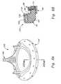
- FIG. 1illustrates a stent assembly 20 comprising an annular, flexible, inner member 22 , and an annular, outer member 24 that is relatively less flexible than the inner member. Both the inner member 22 and the outer member 24 are desirably formed as thin-walled bands that contact one another at their facing surfaces.
- the inner member 22includes an outflow edge 26 that alternates between curvilinear cusps 28 and upstanding commissures 30 .
- the stent assembly 20is used in the construction of a tri-leaflet heart valve, wherein three bio-prosthetic leaflets are suspended within the valve orifice and are attached around the valve generally along the outflow edge 26 of the inner member 22 .
- three bio-prosthetic leafletsare suspended within the valve orifice and are attached around the valve generally along the outflow edge 26 of the inner member 22 .
- more or less than three leafletsmay be utilized, with the number of cusps 28 and commissures 30 varying accordingly.
- the outer member 24also includes an outflow edge that includes curvilinear cusps 32 juxtaposed with the cusps 28 of the inner member 22 . Instead of continuing upward at the commissures, however, the outer member 24 terminates at straight edges 34 rendering the commissures 30 of the inner member 22 unsupported, and therefore highly flexible.
- the inner member 22is formed of a polymer, preferably MYLAR, while the outer member 24 is relatively more rigid, and may be a biocompatible metal such as ELGILOY.
- the inner member 22is secured to the outer member 24 via a plurality of through holes 36 and attachments sutures 38 .
- the stent assembly 20maybe formed of a single member, or the members 22 , 24 may be fastened together using adhesive or other suitable means.
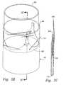
- FIG. 2illustrates an exemplary suture-permeable sewing ring insert 40 used in the construction of the mitral heart valve of the present invention.
- the insert 40is generally annular and includes a solid, preferably curvilinear inflow surface 42 , a solid, generally tubular inner wall 44 , and an open-celled outflow face 46 .
- the insert 40may be molded of a biocompatible material such as silicone rubber, and includes a plurality of internal ribs 48 defining voids 50 therebetween to make up the open-celled construction.
- An outer edge 52 of the outflow face 46is desirably circular, and in one plane, while the inner edge 54 (formed by the outflow edge of the inner wall 44 ) includes a series of depressions 56 ; specifically three, in accordance with the tri-leaflet design of the illustrated heart valve.
- the depressions 56receive cusp portions of a wireform of a heart valve and help prevent axial movement of the wireform and leaflets with respect to the sewing ring.
- Such constructionis shown and described in U.S. Pat. No. 5,928,281, issued Jul. 27, 1999, which disclosure is hereby expressly incorporated by reference. Because the valve position for which the sewing ring insert 40 is useful is non-scalloped, the insert 40 is substantially planar. Furthermore, the exemplary insert 40 is of uniform thickness about its circumference, although non-uniform configurations are possible.
- FIGS. 3A-3Cillustrate initial steps in an assembly process for the mitral heart valve of present invention in which a tubular fabric covering 60 is draped over the stent assembly 20 .
- the fabric covering 60may be a variety of materials, but is typically a polyester such as polyethylene terepthalate.
- FIG. 3Athe tubular fabric covering 60 is shown around the outside of the stent assembly 20 with an upper edge 62 folded down and in so as to be radially inside the upper ends of the commissures 30 .
- a fold line 64is disposed a distance A above the tips of the commissures 30 , which distance is desirably about 1 mm.
- a plurality of pins 66 or other such temporary fixation devicesare utilized to maintain the relative position of the fabric covering 60 in this folded configuration.
- FIGS. 3B and 3Cshow a subsequent step in the attachment of the stent assembly 20 and the fabric covering 60 wherein the lower edge 68 seen in FIG. 3A has been folded inward and pulled upward through the middle of the stent assembly to be disposed above the fold line 64 .
- the lower edge of the fabric covering 60is thus defined by a second fold line 70 disposed some distance below the stent assembly 20 .
- a plurality of pins 72may be used to temporarily hold the relative positions of the stent assembly 20 and fabric covering 60 .
- FIGS. 4A and 4Bschematically illustrate a conventional process of trimming and sewing the upper portions of the fabric covering 60 so as to form a rolled fabric sewing tab 76 along the upper edge of the stent assembly 20 .
- the sewing tab 76extends generally outward from the stent assembly 20 and comprises several layers of the fabric covering 60 rolled together and sutured in place, such as with stitches 78 seen in FIGS. 4A and 4B . Details of the process of forming the sewing tab 76 will be omitted for brevity, but those of skill in the art will understand that there are various ways to form such a tab.
- the lower length of the fabric covering 60 below the backstitch seam 74will be severed at the fold line 70 ( FIG. 3C ) to form a first, outer tubular portion 82 , and a second, inner tubular portion 84 .
- the tubular portions 82 , 84ultimately wrap around the ring-shaped insert 40 to form a sewing ring of the heart valve.
- the outer tubular portion 82is first inverted from its downward position around the inner tubular portion 84 into the upwardly-extending position shown in FIG. 5A surrounding the fabric-covered stent 80 .
- the backstitch seam 74defines a circular line about which the sewing ring will pivot.
- the aforementioned ring-shaped insert 40is shown positioned around the fabric-covered stent 80 , with the upper tubular fabric portion 82 interposed therebetween.
- the ring-shaped insert 40includes a plurality of internal ribs 48 , some of which extend radially.
- the cross-section shown in FIG. 6Bis taken through one of these radial ribs 48 and illustrates a portion of the axially-extending inner wall 44 disposed substantially adjacent and parallel to the outer member 24 of the stent assembly 20 (with reference back to FIG. 1 ).
- the inner member 22 of the stent 24is also shown juxtaposed against the outer member 24 .
- the insert 40therefore extends generally radially outward from the stent assembly 20 , with two layers of the fabric covering 60 disposed therebetween. It should be noted that said two layers of fabric covering (one of which is a portion of the fabric covering encompassing the stent assembly 20 , and one of which is the upper tubular portion 82 ) are not connected in the axial space between the stent assembly 20 and insert 40 . Instead, the two layers of fabric covering extend underneath the stent assembly 20 and are joined together at the backstitch seam 74 .
- FIGS. 6A and 6Balso illustrates an annular assembly fixture 90 having a tubular axial wall 92 , and a radial flange 94 extending outward therefrom.
- the wall 92is sized to fit closely adjacent the inner wall of the fabric-covered stent 80 , while the flange 94 is positioned just below both the stent assembly 20 and insert 40 , with one or more layers of the fabric covering 60 disposed therebetween.
- the fixture 90causes the inner tubular portion 84 of the fabric covering 60 to bend outward at the backstitch seam 74 and presses it against the underside of the generally aligned stent assembly 20 and insert 40 .
- the combination of the sewing tab 76 and the fixture 90axially positions the insert 40 with respect to the stent assembly 20 .
- the ring-shaped insert 40is pushed upward against the sewing tab 76 , and then the fixture 90 added to hold the insert in this preferred position.
- the combined length of the inner tubular portion 82 and outer tubular portion 84 of the fabric covering 60is sufficient to encompass the insert 40 , as will be explained below.
- FIGS. 7A and 7Ba further step of adding a flat, suture-permeable ring 100 to the assembly of the heart valve is shown.
- the inner tubular portion 82is folded outward to cover the outflow face 46 ( FIG. 2 ) of the insert 40 and severed to form an edge 102 at the circular outer edge 52 of the insert.
- the suture-permeable ring 100is then positioned on top of the tubular member 82 , and a sewing fixture 104 is utilized to press the elements flat.
- the suture-permeable ring 100stiffens the insert 40 . That is, in a preferred embodiment, the insert 40 is silicone rubber, and the ring 100 is a stiff textile, preferably non-woven polyester.
- One particularly preferred materialis sold under the trade name REMAY manufactured by Remay, Inc., Old Hickory, Tenn.
- FIG. 7Aillustrates the sewing fixture 104 in perspective, showing a plurality of apertures 106 that receive the commissure portions of the fabric-covered stent 80 projecting therethrough.
- the apertures 106serve to center the annular sewing fixture 104 with respect to the fabric-covered stent 80 and insert 40 .
- the sewing fixture 104includes an inner axially extending wall 108 that fits just inside the axial wall 92 of the assembly fixture 90 , and a radial flange 110 extending outward therefrom.
- the radial flange 110has a tapered outer edge 112 that terminates short of the outer edge of the suture-permeable ring 100 .
- the ring 100is size such that its outer edge is aligned with the insert edge 52 and the edge 102 of the tubular portion 82 . Consequently, a stitch 114 is passed around the circumference of the insert 40 , joining the insert to both the tubular portion 82 and suture-permeable ring 100 at their respective outer edges.
- the sewing fixture 104facilitates the stitching operation because the tapered outer edge 112 provides a clear circular guide. That is, the sewing fixture 110 maintains the respective elements sandwiched together (in conjunction with the assembly fixture 90 ), and exposes just a small peripheral portion of the ring 100 through which the fabricator passes the sewing needle. After this operation, the sewing fixture 104 is removed.
- FIG. 7Balso illustrates the arrangement of the fabric covering 60 around both the stent assembly 20 and the insert 40 at the commissure regions.
- the initial single piece of fabricis shown entirely encompassing the stent assembly 20 , and partially encompassing the insert 40 .
- FIGS. 8A and 8Billustrate a completed stent/sewing ring subassembly 120 comprising the cloth-covered stent 80 attached to the cloth-covered insert 40 , or sewing ring 122 .
- the inner tubular portion 84 of the cloth coveringhas been wrapped upward and inward around an inner edge 124 of the suture-permeable ring 100 .
- the terminal end of the tubular portion 84is folded or otherwise disposed within a recess formed by the recessed ribs 48 of the insert 40 .
- a circular line of stitches 126is provided through the tubular portion 84 , inner edge of the ring 100 , insert 40 , and outer tubular portion 82 .
- the sewing ring 122is exclusively attached to the fabric-covered stent 80 using the cloth covering 60 , and specifically, the two components pivot with respect to one another about the backstitch seam 74 . It should be noted that although the subassembly 120 is complete, the assembly fixture 90 remains in position for subsequent assembly steps.
- an assembly handle 130Prior to attaching a wireform and tissue leaflets to the stent/sewing ring subassembly 120 , an assembly handle 130 is introduced, as seen in FIGS. 9A and 9B .
- the handle 130comprises a generally elongated grip 132 and a valve seat 134 rotatable dispose about one end.
- the valve seat 134is mounted to rotate about an axis 136 that is angled with respect to the longitudinal axis of the elongated grip 132 .
- the valve seat 134has a stepped configuration with a base flange 138 and an upstanding cylinder 140 .
- the stepped configuration of the valve seat 134is sized to fit closely against the assembly fixture 90 , as seen in FIG. 9B .
- the stent/sewing ring subassembly 120can be rotatably mounted about one end of the handle 130 at an angle with respect to the grip 132 .
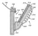
- FIG. 10illustrates a further assembly step wherein a wireform subassembly 140 and a plurality of leaflets 142 are attached to the stent/sewing ring subassembly 120 .
- a fabricatorgrips the handle 130 and is able to pivot the sewing ring 122 radially outward from the fabric-covered stent 80 , as seen by arrow 144 , to facilitate manipulation of a needle 146 having thread 148 attached thereto.
- the needle 146is used to form a stitch line (not shown) joining the wireform subassembly 140 to the fabric-covered stent 80 , and specifically to the rolled fabric tab 76 .
- Outer edges of the leaflets 142are positioned between the stent 80 and wireform subassembly 140 such that the stitch line also passes therethrough.
- the flexible leafletstogether provide the occluding surfaces of the valve.
- the same operation of pivoting the sewing ring 122 outward to facilitate formation of the stitch linecan easily be performed around entire periphery of the heart valve.
- the outward pivoting of the sewing ring 122results in greater visibility of the area in which the stitch line is formed, and reduces the chance of inadvertent puncture of components of the heart valve other than those intended.
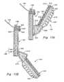
- FIGS. 11A-11Cillustrates an alternative stent/sewing ring subassembly 150 of the present invention in which a sewing ring 152 extends outward from a stent 154 and can be inverted from a position generally facing the inflow end of the subassembly ( FIG. 11C ), to a position generally facing the outflow end ( FIG. 11A ).
- the stent/sewing ring subassembly 150includes a fabric covering that is desirably formed from a single piece of tubular fabric, as will be explained below.
- the stent 154includes a plurality of upstanding commissure posts 156 extending toward the outflow end separated by cusp regions 158 that are convexly curved toward the inflow end. Although not shown in FIGS. 11A-11C , the stent 154 in conjunction with a wireform provides support for a plurality of flexible leaflets therebetween. The flexible leaflets together provide the occluding surfaces of the valve, and in a preferred embodiment are formed from bovine pericardial tissue.
- the stent/sewing ring subassembly 150can be used in a variety of positions within the heart, it is particularly useful in the aortic position which has a scalloped, three-dimensional configuration.
- the aortic valveis located at the outflow of the left ventricle, between the ventricle and the ascending aorta.
- Prosthetic aortic valvesare typically sutured (or attached by other means) to the annulus tissue remaining after the defective host valve has been excised.
- the annulus tissueforms a tough, fibrous ledge extending inward from the surrounding anatomy to define a generally circular orifice between the ventricle and the ascending aorta.
- An exemplary implantation position for an aortic valveis illustrated in FIG.
- the stent/sewing ring subassembly 150is also suitable for implant in the pulmonary position, which has a scalloped configuration, although such valve replacement procedures are less common.
- a typical method of implantationincludes passing a plurality of sutures through the prepared annulus prior to valve delivery.
- the suture lengthsextend out of the surgical field and body and can thus be easily passed through the corresponding locations on the sewing ring, thus “attaching” the valve to the annulus.
- the valveis gently lowered along the array of sutures into position in contact with the annulus, and multiple knots formed securing each pair of suture lengths to the sewing ring.
- the ability to invert the sewing ring 152 into the position shown in FIG. 11Cgenerally extending toward the inflow end of the valve, provides a degree of separation of the sewing ring from the stent 154 , and leaflets support thereby.
- the valve including the inverted sewing ring 152 as in FIG. 11Ccan be “attached” to the host annulus with a reduced risk of puncturing the fragile tissue leaflets. That is, the task of passing the sutures through the sewing ring is simplified because the sewing ring can be pivoted to extend away from the valve body and leaflets. Before or after contact with the annulus 160 , the sewing ring 152 can be inverted as in FIG. 11B into the implantation position of FIG. 11A . Because the greatest axial forces on the aortic valve are during diastole from pressure built up on the outflow side of the valve, the valve will be forced against the annulus 160 and the sewing ring 152 will remain in the position of FIG. 11A .
- FIGS. 12A-12D and 13 A- 13 Billustrate various details of the stent/sewing ring assembly 150 , and in particular the attachment configuration between the sewing ring 152 and stent 154 .
- FIGS. 12A-12Dare various views of a ring-shaped insert 160 that, in conjunction with a fabric covering 162 ( FIGS. 13A-13B ), defines the sewing ring 152 .
- the insert 160includes a circular outer edge 164 and an inner edge 166 having alternating regions of increased ( 168 ) and decreased ( 170 ) radial thickness, corresponding to the cusps and commissure regions, respectively, of the sewing ring 152 formed thereby.
- the insert 160is primarily defined by a band that is angled outward to form a frustoconical shape.
- the outward angle ⁇ of the band 172is preferably in the range of about 20° and 45°, and more preferably is about 30°.
- FIG. 12Cillustrates the regions 168 of increased thickness, which are formed in the cusps of the sewing ring 152 by a curvilinear lower portion 176 and a plurality of upstanding walls 178 .
- the regions of increased ( 168 ) and decreased ( 170 ) radial thicknesshelp the sewing ring 152 invert from an orientation extending generally toward the outflow end of the valve and an orientation extending generally toward the inflow end.
- the walls 178are seen in the plan view of FIG. 12A and define a celled structure.
- the insert 160is molded from silicone rubber.
- the insert 160is shown in two configurations herein; a first configuration being shown in FIGS. 12C and 12D with an internal stiffening member 180 embedded within the band 172 , and also within the thickened regions 168 .
- a stiffening member 182that is separate from the insert 160 is provided, attached to the insert using the fabric covering 162 .
- Both the embedded stiffening member 180 and the separate stiffening member 182serve the same purpose, that is stiffening the relatively soft and flexible insert 160 .
- the stiffening members 180 or 182are relatively more stiff than the material of the insert 160 , and may be made from a non-woven polyester.
- the other main components of the heart valve constructed using the stent/sewing ring subassembly 150are illustrated in cross-section in FIGS. 13A and 13B .
- the valveincludes a stent assembly 190 formed by a combination of an inner stent member 192 and an outer stent member 194 , much like the members 22 and 24 illustrated in FIG. 1 .
- the stent assembly 190is encompassed by a fabric cover, preferably an extension of the fabric cover 162 around the sewing ring 152 .
- a plurality of tissue leaflets 196is secured to the outflow end of the stent 154 using a wireform subassembly 198 .
- the overall shape of the heart valveis similar to the embodiment described earlier, as is evident from FIGS. 11A-11C .
- the fabric cover 162is desirably formed from a single piece of tubular fabric.
- the assembly stepsare similar to those described above for the first embodiment, and include wrapping the tubular fabric around the stent assembly 190 so that the free ends thereof can be joined together in a rolled sewing tab 200 .
- the stent assembly 190is provided with a plurality of through holes 202 extending in a line proximate the outflow edge thereof to enable passage of a stitch line 204 attaching the sewing tab 200 to the stent assembly.
- both the inner member 192 and outer member 194include a plurality of through holes that are aligned for this purpose. The utility of this added stitch line 204 will become apparent below.
- the tubular fabricis severed to define two tubular portions that wrap around the insert 160 (and separate stiffening member 182 if provided) to form the sewing ring 152 .
- an inner tubular portion 210extends around the inflow side of the insert 160 and an outer tubular portion 212 extends around the outflow side.
- the outer tubular portion 212covers the outflow face of the insert 160 and is severed at 214 at the circular outer edge 164 .
- a separate stiffening member 182is used, as illustrated FIGS. 13A and 13B , a stitch line 216 secures it to the outer edges of the insert 160 and outer tubular portion 212 . Otherwise, the stitch line 216 just secures the outer tubular portion 212 to the insert 160 .
- the inner tubular portion 210extends around the outer edge 164 and is secured to both the outer tubular portion 212 and insert 160 somewhere on the outflow face of the sewing ring. In the illustrated embodiment, where a separate stiffening member 182 is used, the inner tubular portion 210 wraps around the stiffening member and a free end 218 is trapped between the stiffening member and the outer tubular portion 212 and secured in that position using a line of stitches 220 .
- the sewing ring 152pivots outward from the position generally adjacent the stent 154 shown in FIG. 13A to the position shown in FIG. 13B .
- the position shown in FIG. 13Acorresponds to FIG. 11A , wherein the sewing ring 152 extends generally toward the outflow end of the valve, while the position shown in FIG. 13B corresponds to that shown in FIG. 11C , with the sewing ring extending generally toward the inflow end.
- the only connection between the sewing ring 152 and the stent 154is provided by the fabric cover 162 (i.e., there are no stitch lines between the insert 160 and the stent assembly 190 , or fabric coverings thereon).
- the portions of the fabric covering 162 around the sewing ring 152 and stent 154are distinguished at a seam 222 , which provides a discrete pivot line (a point in cross-section) for the sewing ring.
- the seam 222is located on the exterior of the stent 154 , as opposed to being located on the inflow end of the stent, as was the case with the earlier described embodiment (see, e.g., FIG. 8B ). Therefore, the sewing ring 152 pivots about the periphery of the stent 154 .
- stitch line 204 connecting the rolled sewing tab 200 to stent assembly 190will now be apparent.
- tensionwill be applied to the fabric cover 162 that tends to rotate the cover around the stent assembly 190 in a clockwise direction, from the perspective of the drawings.
- the stitch line 204maintains the position of the rolled sewing tab 200 at the outflow end of the stent 154 , and resists this tendency to rotate about the stent assembly 190 .
- the two positions shown in FIGS. 11 A/ 13 A and 11 C/ 13 Bare bi-stable.
- the band 172 of the insert 160creates a generally frustoconical sewing ring 152 that can be inverted between orientations extending toward the outflow end and the inflow end.
- the resiliency of the insert 160means that the outer circular edge 164 is stretched and placed in tension as it passes between the two positions, thus biasing the insert one way or the other.
- This bi-stable configurationgreatly assists during both the manufacturing process, and the implantation procedure, as mentioned above.
- the fabric-covered stent/sewing ring subassembly 150is constructed, and the tissue leaflets 196 and wireform assembly 198 are added. Because the sewing ring 152 can be pivoted away from the stent 154 , attaching the leaflets 196 and wireform assembly 198 is simplified. That is, the suturing needle can more easily be passed through the various components to form the stitch line 230 when the sewing ring 154 is displaced out of the way.
- Various fixturesmay be used during the assembly process as was described above with respect to the first embodiment.
- the particular shape of the insert 160further facilitates inversion of the sewing ring 152 between the two stable positions.
- the alternating radially thick ( 168 ) and thin ( 170 ) regionsprovide areas of varying bending strength in the insert 160 .
- the cusp regions of the frustoconical band 172can more easily be pivoted outward because of the thin regions 170 at the commissures, which present relatively little resistance to bending.
- the insert 160tends to snap between the two stable positions. That is, the thick regions 168 provide some rigidity to the structure.
- FIG. 14illustrates a further exemplary stent/sewing ring subassembly 250 of the present invention in which a sewing ring 252 extends outward from a stent 254 and can be inverted from a position generally facing the inflow end of the subassembly, to the illustrated position shown, generally facing the outflow end.
- the stent/sewing ring subassembly 250includes a fabric covering that is desirably formed from a single piece of tubular fabric.
- the stent 254includes a plurality of upstanding commissure posts 256 extending toward the outflow end separated by cusp regions 258 that are convexly curved toward the inflow end.
- the stent 254 in conjunction with a wireformprovides support for a plurality of flexible leaflets therebetween.
- the flexible leafletstogether provide the occluding surfaces of the valve.
- the flexible leafletsare formed from bovine pericardial tissue.
- the stent/sewing ring subassembly 250is in many ways similar to the subassembly 150 in FIGS. 11-13 , but has a reduced size sewing ring insert 260 that provides distinct advantages.
- the insert 260includes an undulating outer edge 264 and an undulating inner edge 266 .
- the insert 260is defined by a band 270 that is angled outward to form a frustoconical shape and a plurality of outwardly extending ribs 272 .
- the outward angle of the band 270is preferably in the range of about 20° and 45°, and more preferably is about 30°.
- the band 270extends in a continuous fashion around entire periphery of the insert 260 .
- An internal stiffening member 274may optionally be embedded within the band 270 .
- the insert 260is molded from silicone rubber.
- the outer edge 264 and inner edge 266undulate in juxtaposition to form three commissure regions 276 extending radially outward from and separated by three cusp regions 278 .
- the radial dimension of the exemplary insert 260is generally constant around its circumference, although small reinforcing ribs 279 may be provided on the inside surface of the cusp regions 278 for stability during manipulation between inflow and outflow orientations.
- the undulating shape of the insert 260helps facilitate the pivoting inversion, and also helps the sewing ring 252 formed thereby conform to the scalloped (undulating) shape as seen in FIG. 14 .
- FIGS. 16B and 17BThe insert 260 is seen in cross-section in FIGS. 16B and 17B assembled into a valve 280 having the stent/sewing ring subassembly 250 .
- FIG. 16Bshows the sewing ring 252 extending generally toward the inflow end of the valve
- FIG. 17Bshows the sewing ring 252 extending generally toward the outflow end of the valve.
- the structure of the stent/sewing ring subassembly 250is somewhat modified from that shown in FIGS. 11-13 .
- the stent 154is seen extending below the sewing ring on the inflow side of the valve.
- This arrangementis suitable for intra-annular placement (e.g., where a portion of the valve is within the annulus proper), but not suitable for supra-annular placement, where no portion of the valve is within the annulus.
- the valve 280includes the sewing ring 252 attached at the inflow end of the stent 254 around the entire periphery thereof.
- the sewing ring 252attaches to the stent 254 at a seam line 282 at this inflow end. As a result, the sewing ring 252 pivots about the stent 254 along the seam line 282 (see FIGS. 16B and 17B ).
- valve 280 having the stent/sewing ring subassembly 250can be used in a variety of positions within the heart, it is particularly useful in either the aortic or pulmonic position which have a scalloped, three-dimensional configuration.
- Two steps in the implantation sequence illustrating the advantageous use of the sewing ringare shown in FIGS. 16A and 17A . Again, the positions of the sewing ring 252 in these two steps are shown in cross-section of the valve in FIGS. 16B and 17B .
- a plurality of sutures 290are passed through the annulus tissue 292 and extended out of the surgical field (and normally out of the patient's body as well).
- the suturesare grouped in interrupted pairs that will eventually be tied off at the sewing ring.
- Each pair of suturesis passed through the sewing ring 252 as shown, with the sewing ring in the outward pivoted configuration. In this way, the surgeon has greater access to the sewing ring 252 and there is less chance of puncturing a leaflet or other delicate valve structure.
- the valve 280is seen attached to a conventional holder 294 at the distal end of a delivery handle 296 .
- the valveis gently guided along the array of pairs of sutures until the sewing ring 252 seats in contact with the annulus.
- the suturesare positioned such that the valve 280 sits in the supra-annular position, not within the annulus proper.
- the sewing ring 252pivots or converts back into the position seen in FIGS. 14 and 17B , generally extending toward the outflow end of the valve.
- the pairs of sutures 290are then tied of at the sewing ring 252 , as seen at 298 . Again, backflow forces will simply force the valve against the annulus, and will not unduly stress the sutures or cause the sewing ring 252 to revert back to the implant orientation.
- a sewing ring 252 having a modified insert 260 sized for use with 21 mm diameter valvescan be combined with a 23 mm valve.
- the pivoting action of the sewing ring 252permits a smaller sewing ring to be used with a particular valve size with equal effectiveness as would be obtained with a conventional, larger sewing ring.
- the valve orificeis increased for a lower pressure drop across the valve, and the small sewing ring 252 helps ensure that the coronary ostia are not occluded, which is often a worry in the supra-annular position.
- the ability of the sewing rings of the present invention to pivot outward from the respective stentsenables the resulting heart valve to have a larger orifice in comparison to earlier valves having the same outer diameter. This is a function of being able to pivot or invert the sewing ring outward during the implantation procedure. Because of this characteristic, the surgeon can more easily isolate the sewing ring with respect to the stent, and there is less likelihood of inadvertently puncturing one of the tissue leaflets, for example.
- the sewing ringcan thus be made smaller in its radial dimension in comparison to earlier sewing rings, which could not pivot outward away from the stent. Such earlier sewing rings thus had to be made somewhat larger to give the surgeon a sufficient suturing platform away from the tissue leaflets. Because the sewing ring of the present invention can be made smaller, a larger valve orifice can be used for the same outer valve diameter.
- the ability to pivot the sewing rings of the current invention away from stentfacilitates manufacture, as was clearly illustrated in FIG. 10 . That is, the smallest valves have a diameter of about 19 mm, and the reader can appreciate that the sewing process for such a small valve is extremely exacting and time-consuming. Indeed, the stitching is typically performed under a magnifying glass.
- the present inventionreduces the strain associated with such a detailed assembly process.
- the ability to effectively separate the sewing ring from the stentgreatly increases the accessibility and visibility of the rolled sewing tab, for instance.
- the present inventionprovides an extremely simplified construction of heart valve. That is, a single piece of tubular fabric is used to encompass both the stent and the sewing ring. The same tubular fabric forms the only connection between two components. Moreover, a minimum number of stitch lines are required, in contrast with earlier valves. With reference to FIG. 8B , the first embodiment requires a total of four stitch lines to encompass both the stent and sewing ring. The second embodiment, as seen in FIG. 13A , also requires a total of four stitch lines, in addition to a desirable fifth stitch line 204 to help prevent relative movement of the cloth around the stent assembly 190 . In earlier tissue heart valves, additional stitch lines were required, thus increasing the assembly time and concurrent expense.
Landscapes
- Health & Medical Sciences (AREA)
- Cardiology (AREA)
- Engineering & Computer Science (AREA)
- Biomedical Technology (AREA)
- Heart & Thoracic Surgery (AREA)
- Transplantation (AREA)
- Oral & Maxillofacial Surgery (AREA)
- Vascular Medicine (AREA)
- Life Sciences & Earth Sciences (AREA)
- Animal Behavior & Ethology (AREA)
- General Health & Medical Sciences (AREA)
- Public Health (AREA)
- Veterinary Medicine (AREA)
- Prostheses (AREA)
Abstract
Description
Claims (21)
Priority Applications (3)
| Application Number | Priority Date | Filing Date | Title |
|---|---|---|---|
| US10/802,314US8366769B2 (en) | 2000-06-01 | 2004-03-17 | Low-profile, pivotable heart valve sewing ring |
| US13/748,216US9439762B2 (en) | 2000-06-01 | 2013-01-23 | Methods of implant of a heart valve with a convertible sewing ring |
| US15/261,468US10238486B2 (en) | 2000-06-01 | 2016-09-09 | Heart valve with integrated stent and sewing ring |
Applications Claiming Priority (2)
| Application Number | Priority Date | Filing Date | Title |
|---|---|---|---|
| US58509800A | 2000-06-01 | 2000-06-01 | |
| US10/802,314US8366769B2 (en) | 2000-06-01 | 2004-03-17 | Low-profile, pivotable heart valve sewing ring |
Related Parent Applications (1)
| Application Number | Title | Priority Date | Filing Date |
|---|---|---|---|
| US58509800AContinuation | 2000-06-01 | 2000-06-01 |
Related Child Applications (1)
| Application Number | Title | Priority Date | Filing Date |
|---|---|---|---|
| US13/748,216DivisionUS9439762B2 (en) | 2000-06-01 | 2013-01-23 | Methods of implant of a heart valve with a convertible sewing ring |
Publications (2)
| Publication Number | Publication Date |
|---|---|
| US20040176839A1 US20040176839A1 (en) | 2004-09-09 |
| US8366769B2true US8366769B2 (en) | 2013-02-05 |
Family
ID=32927827
Family Applications (3)
| Application Number | Title | Priority Date | Filing Date |
|---|---|---|---|
| US10/802,314Active - Reinstated2026-04-26US8366769B2 (en) | 2000-06-01 | 2004-03-17 | Low-profile, pivotable heart valve sewing ring |
| US13/748,216Expired - Fee RelatedUS9439762B2 (en) | 2000-06-01 | 2013-01-23 | Methods of implant of a heart valve with a convertible sewing ring |
| US15/261,468Expired - Fee RelatedUS10238486B2 (en) | 2000-06-01 | 2016-09-09 | Heart valve with integrated stent and sewing ring |
Family Applications After (2)
| Application Number | Title | Priority Date | Filing Date |
|---|---|---|---|
| US13/748,216Expired - Fee RelatedUS9439762B2 (en) | 2000-06-01 | 2013-01-23 | Methods of implant of a heart valve with a convertible sewing ring |
| US15/261,468Expired - Fee RelatedUS10238486B2 (en) | 2000-06-01 | 2016-09-09 | Heart valve with integrated stent and sewing ring |
Country Status (1)
| Country | Link |
|---|---|
| US (3) | US8366769B2 (en) |
Cited By (49)
| Publication number | Priority date | Publication date | Assignee | Title |
|---|---|---|---|---|
| US20120143322A1 (en)* | 2001-08-28 | 2012-06-07 | Edwards Lifesciences Corporation | Three-dimensional annuloplasty ring |
| US9220594B2 (en) | 2008-07-15 | 2015-12-29 | St. Jude Medical, Inc. | Collapsible and re-expandable prosthetic heart valve cuff designs and complementary technological applications |
| US9241794B2 (en) | 2007-09-26 | 2016-01-26 | St. Jude Medical, Inc. | Collapsible prosthetic heart valves |
| US9326856B2 (en) | 2013-03-14 | 2016-05-03 | St. Jude Medical, Cardiology Division, Inc. | Cuff configurations for prosthetic heart valve |
| US9333074B2 (en) | 2009-04-15 | 2016-05-10 | Edwards Lifesciences Cardiaq Llc | Vascular implant and delivery system |
| US9339274B2 (en) | 2013-03-12 | 2016-05-17 | St. Jude Medical, Cardiology Division, Inc. | Paravalvular leak occlusion device for self-expanding heart valves |
| US9339377B2 (en) | 2008-09-29 | 2016-05-17 | Edwards Lifesciences Cardiaq Llc | Body cavity prosthesis |
| US9398951B2 (en) | 2013-03-12 | 2016-07-26 | St. Jude Medical, Cardiology Division, Inc. | Self-actuating sealing portions for paravalvular leak protection |
| US9532868B2 (en) | 2007-09-28 | 2017-01-03 | St. Jude Medical, Inc. | Collapsible-expandable prosthetic heart valves with structures for clamping native tissue |
| US9554897B2 (en) | 2011-04-28 | 2017-01-31 | Neovasc Tiara Inc. | Methods and apparatus for engaging a valve prosthesis with tissue |
| US9572665B2 (en) | 2013-04-04 | 2017-02-21 | Neovasc Tiara Inc. | Methods and apparatus for delivering a prosthetic valve to a beating heart |
| US9597183B2 (en) | 2008-10-01 | 2017-03-21 | Edwards Lifesciences Cardiaq Llc | Delivery system for vascular implant |
| US9668857B2 (en) | 2013-11-06 | 2017-06-06 | St. Jude Medical, Cardiology Division, Inc. | Paravalvular leak sealing mechanism |
| US9668858B2 (en) | 2014-05-16 | 2017-06-06 | St. Jude Medical, Cardiology Division, Inc. | Transcatheter valve with paravalvular leak sealing ring |
| US9681951B2 (en) | 2013-03-14 | 2017-06-20 | Edwards Lifesciences Cardiaq Llc | Prosthesis with outer skirt and anchors |
| US9700409B2 (en) | 2013-11-06 | 2017-07-11 | St. Jude Medical, Cardiology Division, Inc. | Reduced profile prosthetic heart valve |
| US9713529B2 (en) | 2011-04-28 | 2017-07-25 | Neovasc Tiara Inc. | Sequentially deployed transcatheter mitral valve prosthesis |
| US9757230B2 (en) | 2014-05-16 | 2017-09-12 | St. Jude Medical, Cardiology Division, Inc. | Stent assembly for use in prosthetic heart valves |
| US9770329B2 (en) | 2010-05-05 | 2017-09-26 | Neovasc Tiara Inc. | Transcatheter mitral valve prosthesis |
| US9820852B2 (en) | 2014-01-24 | 2017-11-21 | St. Jude Medical, Cardiology Division, Inc. | Stationary intra-annular halo designs for paravalvular leak (PVL) reduction—active channel filling cuff designs |
| US9867697B2 (en) | 2013-03-12 | 2018-01-16 | St. Jude Medical, Cardiology Division, Inc. | Self-actuating sealing portions for a paravalvular leak protection |
| US9913715B2 (en) | 2013-11-06 | 2018-03-13 | St. Jude Medical, Cardiology Division, Inc. | Paravalvular leak sealing mechanism |
| US9962260B2 (en) | 2015-03-24 | 2018-05-08 | St. Jude Medical, Cardiology Division, Inc. | Prosthetic mitral valve |
| US10016275B2 (en) | 2012-05-30 | 2018-07-10 | Neovasc Tiara Inc. | Methods and apparatus for loading a prosthesis onto a delivery system |
| US10117742B2 (en) | 2013-09-12 | 2018-11-06 | St. Jude Medical, Cardiology Division, Inc. | Stent designs for prosthetic heart valves |
| US10130467B2 (en) | 2014-05-16 | 2018-11-20 | St. Jude Medical, Cardiology Division, Inc. | Subannular sealing for paravalvular leak protection |
| US10143551B2 (en) | 2014-03-31 | 2018-12-04 | St. Jude Medical, Cardiology Division, Inc. | Paravalvular sealing via extended cuff mechanisms |
| US10271949B2 (en) | 2013-03-12 | 2019-04-30 | St. Jude Medical, Cardiology Division, Inc. | Paravalvular leak occlusion device for self-expanding heart valves |
| US10279092B2 (en) | 2013-10-22 | 2019-05-07 | Heartware, Inc. | Anchored mounting ring |
| US10321991B2 (en) | 2013-06-19 | 2019-06-18 | St. Jude Medical, Cardiology Division, Inc. | Collapsible valve having paravalvular leak protection |
| US10441421B2 (en) | 2016-10-28 | 2019-10-15 | St. Jude Medical, Cardiology Division, Inc. | Prosthetic mitral valve |
| US10441417B2 (en) | 2009-02-27 | 2019-10-15 | St. Jude Medical, Llc | Stent features for collapsible prosthetic heart valves |
| US10456249B2 (en) | 2016-09-15 | 2019-10-29 | St. Jude Medical, Cardiology Division, Inc. | Prosthetic heart valve with paravalvular leak mitigation features |
| US10548722B2 (en) | 2016-08-26 | 2020-02-04 | St. Jude Medical, Cardiology Division, Inc. | Prosthetic heart valve with paravalvular leak mitigation features |
| USD875250S1 (en) | 2017-05-15 | 2020-02-11 | St. Jude Medical, Cardiology Division, Inc. | Stent having tapered aortic struts |
| USD875935S1 (en) | 2017-05-15 | 2020-02-18 | St. Jude Medical, Cardiology Division, Inc. | Stent having tapered struts |
| US10583002B2 (en) | 2013-03-11 | 2020-03-10 | Neovasc Tiara Inc. | Prosthetic valve with anti-pivoting mechanism |
| USD889653S1 (en) | 2017-05-15 | 2020-07-07 | St. Jude Medical, Cardiology Division, Inc. | Stent having tapered struts |
| US10945836B2 (en) | 2013-11-19 | 2021-03-16 | St. Jude Medical, Cardiology Division, Inc. | Sealing structures for paravalvular leak protection |
| US11033385B2 (en) | 2014-01-24 | 2021-06-15 | St. Jude Medical, Cardiology Division, Inc. | Stationary intra-annular halo designs for paravalvular leak (PVL) reduction-passive channel filling cuff designs |
| US11246706B2 (en) | 2014-03-26 | 2022-02-15 | St. Jude Medical, Cardiology Division, Inc. | Transcatheter mitral valve stent frames |
| US11273030B2 (en) | 2018-12-26 | 2022-03-15 | St. Jude Medical, Cardiology Division, Inc. | Elevated outer cuff for reducing paravalvular leakage and increasing stent fatigue life |
| US11284996B2 (en) | 2018-09-20 | 2022-03-29 | St. Jude Medical, Cardiology Division, Inc. | Attachment of leaflets to prosthetic heart valve |
| US11364117B2 (en) | 2018-10-15 | 2022-06-21 | St. Jude Medical, Cardiology Division, Inc. | Braid connections for prosthetic heart valves |
| US11382751B2 (en)* | 2017-10-24 | 2022-07-12 | St. Jude Medical, Cardiology Division, Inc. | Self-expandable filler for mitigating paravalvular leak |
| US11471277B2 (en) | 2018-12-10 | 2022-10-18 | St. Jude Medical, Cardiology Division, Inc. | Prosthetic tricuspid valve replacement design |
| US11672652B2 (en) | 2014-02-18 | 2023-06-13 | St. Jude Medical, Cardiology Division, Inc. | Bowed runners for paravalvular leak protection |
| US11813413B2 (en) | 2018-03-27 | 2023-11-14 | St. Jude Medical, Cardiology Division, Inc. | Radiopaque outer cuff for transcatheter valve |
| WO2025079086A1 (en)* | 2023-10-11 | 2025-04-17 | Mathew Kurian Valikapathalil | Prosthetic heart valve with sewing ring |
Families Citing this family (113)
| Publication number | Priority date | Publication date | Assignee | Title |
|---|---|---|---|---|
| US6440164B1 (en) | 1999-10-21 | 2002-08-27 | Scimed Life Systems, Inc. | Implantable prosthetic valve |
| US6602286B1 (en) | 2000-10-26 | 2003-08-05 | Ernst Peter Strecker | Implantable valve system |
| US7201771B2 (en)* | 2001-12-27 | 2007-04-10 | Arbor Surgical Technologies, Inc. | Bioprosthetic heart valve |
| US7007698B2 (en) | 2002-04-03 | 2006-03-07 | Boston Scientific Corporation | Body lumen closure |
| US6752828B2 (en) | 2002-04-03 | 2004-06-22 | Scimed Life Systems, Inc. | Artificial valve |
| US7959674B2 (en) | 2002-07-16 | 2011-06-14 | Medtronic, Inc. | Suture locking assembly and method of use |
| AU2003285943B2 (en) | 2002-10-24 | 2008-08-21 | Boston Scientific Limited | Venous valve apparatus and method |
| US8551162B2 (en) | 2002-12-20 | 2013-10-08 | Medtronic, Inc. | Biologically implantable prosthesis |
| US6945957B2 (en) | 2002-12-30 | 2005-09-20 | Scimed Life Systems, Inc. | Valve treatment catheter and methods |
| US8021421B2 (en) | 2003-08-22 | 2011-09-20 | Medtronic, Inc. | Prosthesis heart valve fixturing device |
| US7556647B2 (en) | 2003-10-08 | 2009-07-07 | Arbor Surgical Technologies, Inc. | Attachment device and methods of using the same |
| US8128681B2 (en) | 2003-12-19 | 2012-03-06 | Boston Scientific Scimed, Inc. | Venous valve apparatus, system, and method |
| US7854761B2 (en) | 2003-12-19 | 2010-12-21 | Boston Scientific Scimed, Inc. | Methods for venous valve replacement with a catheter |
| US7566343B2 (en) | 2004-09-02 | 2009-07-28 | Boston Scientific Scimed, Inc. | Cardiac valve, system, and method |
| US20060173490A1 (en) | 2005-02-01 | 2006-08-03 | Boston Scientific Scimed, Inc. | Filter system and method |
| US7854755B2 (en) | 2005-02-01 | 2010-12-21 | Boston Scientific Scimed, Inc. | Vascular catheter, system, and method |
| US7878966B2 (en) | 2005-02-04 | 2011-02-01 | Boston Scientific Scimed, Inc. | Ventricular assist and support device |
| US7670368B2 (en) | 2005-02-07 | 2010-03-02 | Boston Scientific Scimed, Inc. | Venous valve apparatus, system, and method |
| US7780722B2 (en) | 2005-02-07 | 2010-08-24 | Boston Scientific Scimed, Inc. | Venous valve apparatus, system, and method |
| US7867274B2 (en) | 2005-02-23 | 2011-01-11 | Boston Scientific Scimed, Inc. | Valve apparatus, system and method |
| US8083793B2 (en)* | 2005-02-28 | 2011-12-27 | Medtronic, Inc. | Two piece heart valves including multiple lobe valves and methods for implanting them |
| US20060195186A1 (en)* | 2005-02-28 | 2006-08-31 | Drews Michael J | Connectors for two piece heart valves and methods for implanting such heart valves |
| US7513909B2 (en)* | 2005-04-08 | 2009-04-07 | Arbor Surgical Technologies, Inc. | Two-piece prosthetic valves with snap-in connection and methods for use |
| US7722666B2 (en) | 2005-04-15 | 2010-05-25 | Boston Scientific Scimed, Inc. | Valve apparatus, system and method |
| US8211169B2 (en) | 2005-05-27 | 2012-07-03 | Medtronic, Inc. | Gasket with collar for prosthetic heart valves and methods for using them |
| US7739971B2 (en)* | 2005-06-07 | 2010-06-22 | Edwards Lifesciences Corporation | Systems and methods for assembling components of a fabric-covered prosthetic heart valve |
| US8012198B2 (en) | 2005-06-10 | 2011-09-06 | Boston Scientific Scimed, Inc. | Venous valve, system, and method |
| US7776084B2 (en)* | 2005-07-13 | 2010-08-17 | Edwards Lifesciences Corporation | Prosthetic mitral heart valve having a contoured sewing ring |
| US7569071B2 (en) | 2005-09-21 | 2009-08-04 | Boston Scientific Scimed, Inc. | Venous valve, system, and method with sinus pocket |
| EP1959864B1 (en)* | 2005-12-07 | 2018-03-07 | Medtronic, Inc. | Connection systems for two piece prosthetic heart valve assemblies |
| US7799038B2 (en) | 2006-01-20 | 2010-09-21 | Boston Scientific Scimed, Inc. | Translumenal apparatus, system, and method |
| US7967857B2 (en) | 2006-01-27 | 2011-06-28 | Medtronic, Inc. | Gasket with spring collar for prosthetic heart valves and methods for making and using them |
| JP2009535128A (en) | 2006-04-29 | 2009-10-01 | アーバー・サージカル・テクノロジーズ・インコーポレイテッド | Multi-part prosthetic heart valve assembly and apparatus and method for delivering the same |
| US8020503B2 (en)* | 2006-07-31 | 2011-09-20 | Edwards Lifesciences Corporation | Automated surgical implant sewing system and method |
| US8163011B2 (en)* | 2006-10-06 | 2012-04-24 | BioStable Science & Engineering, Inc. | Intra-annular mounting frame for aortic valve repair |
| US7879087B2 (en)* | 2006-10-06 | 2011-02-01 | Edwards Lifesciences Corporation | Mitral and tricuspid annuloplasty rings |
| WO2008091493A1 (en) | 2007-01-08 | 2008-07-31 | California Institute Of Technology | In-situ formation of a valve |
| US7967853B2 (en) | 2007-02-05 | 2011-06-28 | Boston Scientific Scimed, Inc. | Percutaneous valve, system and method |
| US20080294247A1 (en)* | 2007-05-25 | 2008-11-27 | Medical Entrepreneurs Ii, Inc. | Prosthetic Heart Valve |
| US8828079B2 (en) | 2007-07-26 | 2014-09-09 | Boston Scientific Scimed, Inc. | Circulatory valve, system and method |
| US7892276B2 (en) | 2007-12-21 | 2011-02-22 | Boston Scientific Scimed, Inc. | Valve with delayed leaflet deployment |
| CN102438553A (en)* | 2009-03-31 | 2012-05-02 | 天成医疗有限公司 | Leaflet alignment fixture and method of use |
| US8870950B2 (en) | 2009-12-08 | 2014-10-28 | Mitral Tech Ltd. | Rotation-based anchoring of an implant |
| US20110224785A1 (en) | 2010-03-10 | 2011-09-15 | Hacohen Gil | Prosthetic mitral valve with tissue anchors |
| US8992604B2 (en) | 2010-07-21 | 2015-03-31 | Mitraltech Ltd. | Techniques for percutaneous mitral valve replacement and sealing |
| US9132009B2 (en)* | 2010-07-21 | 2015-09-15 | Mitraltech Ltd. | Guide wires with commissural anchors to advance a prosthetic valve |
| US11653910B2 (en) | 2010-07-21 | 2023-05-23 | Cardiovalve Ltd. | Helical anchor implantation |
| US9763657B2 (en) | 2010-07-21 | 2017-09-19 | Mitraltech Ltd. | Techniques for percutaneous mitral valve replacement and sealing |
| US9744033B2 (en) | 2011-04-01 | 2017-08-29 | W.L. Gore & Associates, Inc. | Elastomeric leaflet for prosthetic heart valves |
| US8852272B2 (en) | 2011-08-05 | 2014-10-07 | Mitraltech Ltd. | Techniques for percutaneous mitral valve replacement and sealing |
| WO2013021374A2 (en) | 2011-08-05 | 2013-02-14 | Mitraltech Ltd. | Techniques for percutaneous mitral valve replacement and sealing |
| US9668859B2 (en) | 2011-08-05 | 2017-06-06 | California Institute Of Technology | Percutaneous heart valve delivery systems |
| EP2739214B1 (en) | 2011-08-05 | 2018-10-10 | Cardiovalve Ltd | Percutaneous mitral valve replacement and sealing |
| US20140324164A1 (en) | 2011-08-05 | 2014-10-30 | Mitraltech Ltd. | Techniques for percutaneous mitral valve replacement and sealing |
| US9554806B2 (en) | 2011-09-16 | 2017-01-31 | W. L. Gore & Associates, Inc. | Occlusive devices |
| EP2842517A1 (en)* | 2011-12-29 | 2015-03-04 | Sorin Group Italia S.r.l. | A kit for implanting prosthetic vascular conduits |
| EP2856972B1 (en)* | 2012-05-24 | 2019-01-16 | Shanghai Cingular Biotech Corp | Artificial heart valve |
| CN102652694B (en)* | 2012-05-24 | 2014-06-25 | 上海欣吉特生物科技有限公司 | Prosthetic heart valve |
| US9283072B2 (en) | 2012-07-25 | 2016-03-15 | W. L. Gore & Associates, Inc. | Everting transcatheter valve and methods |
| US10376360B2 (en) | 2012-07-27 | 2019-08-13 | W. L. Gore & Associates, Inc. | Multi-frame prosthetic valve apparatus and methods |
| US9968443B2 (en) | 2012-12-19 | 2018-05-15 | W. L. Gore & Associates, Inc. | Vertical coaptation zone in a planar portion of prosthetic heart valve leaflet |
| US10966820B2 (en) | 2012-12-19 | 2021-04-06 | W. L. Gore & Associates, Inc. | Geometric control of bending character in prosthetic heart valve leaflets |
| US10039638B2 (en) | 2012-12-19 | 2018-08-07 | W. L. Gore & Associates, Inc. | Geometric prosthetic heart valves |
| US9737398B2 (en) | 2012-12-19 | 2017-08-22 | W. L. Gore & Associates, Inc. | Prosthetic valves, frames and leaflets and methods thereof |
| US9101469B2 (en) | 2012-12-19 | 2015-08-11 | W. L. Gore & Associates, Inc. | Prosthetic heart valve with leaflet shelving |
| US10321986B2 (en) | 2012-12-19 | 2019-06-18 | W. L. Gore & Associates, Inc. | Multi-frame prosthetic heart valve |
| US9144492B2 (en) | 2012-12-19 | 2015-09-29 | W. L. Gore & Associates, Inc. | Truncated leaflet for prosthetic heart valves, preformed valve |
| US20150351906A1 (en) | 2013-01-24 | 2015-12-10 | Mitraltech Ltd. | Ventricularly-anchored prosthetic valves |
| US9655719B2 (en)* | 2013-01-29 | 2017-05-23 | St. Jude Medical, Cardiology Division, Inc. | Surgical heart valve flexible stent frame stiffener |
| US11007058B2 (en)* | 2013-03-15 | 2021-05-18 | Edwards Lifesciences Corporation | Valved aortic conduits |
| WO2014144247A1 (en) | 2013-03-15 | 2014-09-18 | Arash Kheradvar | Handle mechanism and functionality for repositioning and retrieval of transcatheter heart valves |
| US11911258B2 (en) | 2013-06-26 | 2024-02-27 | W. L. Gore & Associates, Inc. | Space filling devices |
| US9504565B2 (en) | 2013-12-06 | 2016-11-29 | W. L. Gore & Associates, Inc. | Asymmetric opening and closing prosthetic valve leaflet |
| EP3131504B1 (en)* | 2014-04-14 | 2023-03-15 | St. Jude Medical, Cardiology Division, Inc. | Leaflet abrasion mitigation in prosthetic heart valves |
| EP3174502B1 (en) | 2014-07-30 | 2022-04-06 | Cardiovalve Ltd | Apparatus for implantation of an articulatable prosthetic valve |
| BR112017003339A2 (en) | 2014-08-18 | 2017-11-28 | Gore & Ass | integral seamed structure for protective valves |
| US9827094B2 (en) | 2014-09-15 | 2017-11-28 | W. L. Gore & Associates, Inc. | Prosthetic heart valve with retention elements |
| US20160175094A1 (en)* | 2014-12-23 | 2016-06-23 | Howard Song | Morphological sewing cuff assembly for heart valve |
| CN110141399B (en) | 2015-02-05 | 2021-07-27 | 卡迪尔维尔福股份有限公司 | Prosthetic valve with axial sliding frame |
| US9974651B2 (en) | 2015-02-05 | 2018-05-22 | Mitral Tech Ltd. | Prosthetic valve with axially-sliding frames |
| DE102015206097A1 (en) | 2015-04-02 | 2016-10-06 | Hans-Hinrich Sievers | Heart valve prosthesis |
| CA2986047C (en) | 2015-05-14 | 2020-11-10 | W. L. Gore & Associates, Inc. | Devices and methods for occlusion of an atrial appendage |
| US10531866B2 (en) | 2016-02-16 | 2020-01-14 | Cardiovalve Ltd. | Techniques for providing a replacement valve and transseptal communication |
| US20200146854A1 (en) | 2016-05-16 | 2020-05-14 | Elixir Medical Corporation | Methods and devices for heart valve repair |
| WO2019222694A1 (en)* | 2018-05-18 | 2019-11-21 | Elixir Medical Corporation | Methods and devices for heart valve repair |
| GB201612180D0 (en) | 2016-07-13 | 2016-08-24 | Ucl Business Plc | Bioprosthetic heart valve |
| US20190231525A1 (en) | 2016-08-01 | 2019-08-01 | Mitraltech Ltd. | Minimally-invasive delivery systems |
| CA3031187A1 (en) | 2016-08-10 | 2018-02-15 | Cardiovalve Ltd. | Prosthetic valve with concentric frames |
| USD800908S1 (en) | 2016-08-10 | 2017-10-24 | Mitraltech Ltd. | Prosthetic valve element |
| WO2018184226A1 (en)* | 2017-04-07 | 2018-10-11 | 上海甲悦医疗器械有限公司 | Prosthetic valve and prosthetic valve implanting method |
| US11246704B2 (en) | 2017-08-03 | 2022-02-15 | Cardiovalve Ltd. | Prosthetic heart valve |
| US10575948B2 (en) | 2017-08-03 | 2020-03-03 | Cardiovalve Ltd. | Prosthetic heart valve |
| US12064347B2 (en) | 2017-08-03 | 2024-08-20 | Cardiovalve Ltd. | Prosthetic heart valve |
| US11793633B2 (en) | 2017-08-03 | 2023-10-24 | Cardiovalve Ltd. | Prosthetic heart valve |
| US10537426B2 (en) | 2017-08-03 | 2020-01-21 | Cardiovalve Ltd. | Prosthetic heart valve |
| US10888421B2 (en) | 2017-09-19 | 2021-01-12 | Cardiovalve Ltd. | Prosthetic heart valve with pouch |
| WO2019055577A1 (en) | 2017-09-12 | 2019-03-21 | W. L. Gore & Associates, Inc. | Leaflet frame attachment for prosthetic valves |
| CN111163728B (en) | 2017-09-27 | 2022-04-29 | W.L.戈尔及同仁股份有限公司 | Prosthetic valve with mechanically coupled leaflets |
| CN111132636B (en) | 2017-09-27 | 2022-04-08 | W.L.戈尔及同仁股份有限公司 | Prosthetic valve with expandable frame and related systems and methods |
| US11090153B2 (en) | 2017-10-13 | 2021-08-17 | W. L. Gore & Associates, Inc. | Telescoping prosthetic valve and delivery system |
| US11173023B2 (en) | 2017-10-16 | 2021-11-16 | W. L. Gore & Associates, Inc. | Medical devices and anchors therefor |
| CN111295158A (en) | 2017-10-31 | 2020-06-16 | W.L.戈尔及同仁股份有限公司 | Medical valve and valve leaflet for promoting tissue ingrowth |
| US11154397B2 (en) | 2017-10-31 | 2021-10-26 | W. L. Gore & Associates, Inc. | Jacket for surgical heart valve |
| JP7072062B2 (en) | 2017-10-31 | 2022-05-19 | ダブリュ.エル.ゴア アンド アソシエイツ,インコーポレイティド | Transcatheter placement system and related methods |
| EP3703618A1 (en) | 2017-10-31 | 2020-09-09 | W. L. Gore & Associates, Inc. | Prosthetic heart valve |
| GB201720803D0 (en) | 2017-12-13 | 2018-01-24 | Mitraltech Ltd | Prosthetic Valve and delivery tool therefor |
| GB201800399D0 (en) | 2018-01-10 | 2018-02-21 | Mitraltech Ltd | Temperature-control during crimping of an implant |
| EP3595589B1 (en) | 2018-05-21 | 2024-10-09 | Aran Biomedical Teoranta | Insertable medical devices with low profile composite coverings |
| CN118065060A (en) | 2018-08-22 | 2024-05-24 | 爱德华兹生命科学公司 | Automated heart valve manufacturing apparatus and method |
| USD926322S1 (en) | 2018-11-07 | 2021-07-27 | W. L. Gore & Associates, Inc. | Heart valve cover |
| US11497601B2 (en) | 2019-03-01 | 2022-11-15 | W. L. Gore & Associates, Inc. | Telescoping prosthetic valve with retention element |
| KR20230021701A (en) | 2020-06-09 | 2023-02-14 | 에드워즈 라이프사이언시스 코포레이션 | Automated sewing and thread management |
| US12357459B2 (en) | 2020-12-03 | 2025-07-15 | Cardiovalve Ltd. | Transluminal delivery system |
Citations (50)
| Publication number | Priority date | Publication date | Assignee | Title |
|---|---|---|---|---|
| US3781969A (en) | 1972-08-11 | 1974-01-01 | Medical Inc | Method of forming rotatable suturing member on a device |
| US3839741A (en) | 1972-11-17 | 1974-10-08 | J Haller | Heart valve and retaining means therefor |
| US4084268A (en) | 1976-04-22 | 1978-04-18 | Shiley Laboratories, Incorporated | Prosthetic tissue heart valve |
| US4197593A (en) | 1978-03-03 | 1980-04-15 | Kastec Corporation | Rotatably positionable heart valve and method |
| US4345340A (en) | 1981-05-07 | 1982-08-24 | Vascor, Inc. | Stent for mitral/tricuspid heart valve |
| WO1982002829A1 (en) | 1981-02-04 | 1982-09-02 | Pop D Popa Ioan | Cardiac valvular bioprosthesis and the proceeding of achievement |
| EP0070259A2 (en) | 1981-07-14 | 1983-01-19 | SORIN BIOMEDICA S.p.A. | Heart valve prosthesis |
| EP0119357A1 (en) | 1983-01-17 | 1984-09-26 | Baxter Travenol Laboratories, Inc. | Suture rings for heart valves |
| US4477930A (en) | 1982-09-28 | 1984-10-23 | Mitral Medical International, Inc. | Natural tissue heat valve and method of making same |
| EP0075530B1 (en) | 1981-09-02 | 1985-12-18 | Medical Incorporated | Prosthetic heart valve |
| US4605407A (en) | 1983-01-11 | 1986-08-12 | The University Of Sheffield | Heart valve replacements |
| EP0200926A2 (en) | 1985-04-05 | 1986-11-12 | Abiomed Cardiovascular Inc. | Prosthetic heart valve |
| US4626255A (en) | 1983-09-23 | 1986-12-02 | Christian Weinhold | Heart valve bioprothesis |
| US4680031A (en) | 1982-11-29 | 1987-07-14 | Tascon Medical Technology Corporation | Heart valve prosthesis |
| US4705516A (en) | 1983-04-20 | 1987-11-10 | Barone Hector D | Setting for a cardiac valve |
| US4816029A (en) | 1981-05-07 | 1989-03-28 | Medtronic, Inc. | Stent for aortic heart valve |
| US4863460A (en) | 1986-03-04 | 1989-09-05 | Sta-Set Corporation | Suture rings for heart valves |
| US4865870A (en) | 1988-07-07 | 1989-09-12 | Becton, Dickinson And Company | Method for rendering a substrate surface antithrombogenic |
| US4865600A (en) | 1981-08-25 | 1989-09-12 | Baxter International Inc. | Mitral valve holder |
| US4892540A (en) | 1988-04-21 | 1990-01-09 | Sorin Biomedica S.P.A. | Two-leaflet prosthetic heart valve |
| EP0350302A1 (en) | 1988-07-07 | 1990-01-10 | Medtronic, Inc. | Heart valve prosthesis |
| US5035709A (en) | 1990-03-29 | 1991-07-30 | Baxter International Inc. | Mechanical heart valve with compliant sewing ring |
| US5072431A (en) | 1989-05-23 | 1991-12-10 | Sony Corporation | Magneto-optical disk recording apparatus |
| US5071431A (en) | 1990-11-07 | 1991-12-10 | Carbomedics, Inc. | Suture rings for heart valves and method of securing suture rings to heart valves |
| US5104406A (en) | 1990-02-21 | 1992-04-14 | Sorin Biomedica S.P.A. | Heart valve prosthesis |
| US5147391A (en) | 1990-04-11 | 1992-09-15 | Carbomedics, Inc. | Bioprosthetic heart valve with semi-permeable commissure posts and deformable leaflets |
| WO1992019184A1 (en) | 1991-05-08 | 1992-11-12 | Nika Health Products Limited | Support for a heart valve prosthesis |
| US5178633A (en) | 1992-04-21 | 1993-01-12 | Carbon Implants Inc. | Suture ring for heart valve prosthesis |
| EP0541215A1 (en) | 1991-10-31 | 1993-05-12 | Ats Medical, Inc. | Heart valve prosthesis |
| US5243330A (en) | 1990-12-04 | 1993-09-07 | Cerberus Ag | Fire detector system and method |
| US5258023A (en) | 1992-02-12 | 1993-11-02 | Reger Medical Development, Inc. | Prosthetic heart valve |
| WO1994001060A1 (en) | 1992-07-10 | 1994-01-20 | Adiam Medizintechnik Gmbh & Co. Kg | Support housing for valve and closure members |
| US5354330A (en) | 1991-10-31 | 1994-10-11 | Ats Medical Inc. | Heart valve prosthesis |
| US5360014A (en) | 1993-11-10 | 1994-11-01 | Carbomedics, Inc. | Sizing apparatus for heart valve with supra annular suture ring |
| US5370684A (en) | 1986-12-12 | 1994-12-06 | Sorin Biomedica S.P.A. | Prosthesis of polymeric material coated with biocompatible carbon |
| US5397346A (en) | 1992-04-28 | 1995-03-14 | Carbomedics, Inc. | Prosthetic heart valve with sewing ring |
| US5397348A (en) | 1993-12-13 | 1995-03-14 | Carbomedics, Inc. | Mechanical heart valve with compressible stiffening ring |
| WO1995028899A1 (en) | 1994-04-22 | 1995-11-02 | Medtronic, Inc. | Stented bioprosthetic heart valve |
| US5480425A (en) | 1994-06-09 | 1996-01-02 | Carbomedics, Inc. | Integrated heart valve rotator and holder |
| US5487760A (en) | 1994-03-08 | 1996-01-30 | Ats Medical, Inc. | Heart valve prosthesis incorporating electronic sensing, monitoring and/or pacing circuitry |
| US5571175A (en) | 1995-06-07 | 1996-11-05 | St. Jude Medical, Inc. | Suture guard for prosthetic heart valve |
| US5607470A (en) | 1995-05-01 | 1997-03-04 | Milo; Simcha | Suture rings for prosthetic heart valves |
| US5755783A (en) | 1996-07-29 | 1998-05-26 | Stobie; Robert | Suture rings for rotatable artificial heart valves |
| US5766240A (en) | 1996-10-28 | 1998-06-16 | Medtronic, Inc. | Rotatable suturing ring for prosthetic heart valve |
| US5824069A (en) | 1996-09-13 | 1998-10-20 | Medtronic, Inc. | Prosthetic heart valve with suturing member having non-uniform radial width |
| US5855603A (en) | 1995-03-24 | 1999-01-05 | Republic Medical Inc. | Suture ring for heart valve prosthesis |
| US5876436A (en) | 1994-10-21 | 1999-03-02 | St. Jude Medical, Inc. | Rotatable cuff assembly for a heart valve prosthesis |
| US5928281A (en) | 1997-03-27 | 1999-07-27 | Baxter International Inc. | Tissue heart valves |
| US6045576A (en) | 1997-09-16 | 2000-04-04 | Baxter International Inc. | Sewing ring having increased annular coaptation |
| WO2001012105A1 (en) | 1999-08-16 | 2001-02-22 | Citron Limited | Autologous tissue suture ring used in heart valve implantation |
Family Cites Families (242)
| Publication number | Priority date | Publication date | Assignee | Title |
|---|---|---|---|---|
| US3143742A (en) | 1963-03-19 | 1964-08-11 | Surgitool Inc | Prosthetic sutureless heart valve |
| US3320972A (en) | 1964-04-16 | 1967-05-23 | Roy F High | Prosthetic tricuspid valve and method of and device for fabricating same |
| US3371352A (en) | 1965-01-19 | 1968-03-05 | Edwards Lab Inc | Heart valve for quick implantation having provision for ingrowth of tissue |
| GB1172990A (en) | 1965-12-11 | 1969-12-03 | Valery Ivanovich Shumakov | Cardiac Valve Prosthesis and Instrument for Mounting and Fixing it in Position |
| US3574865A (en) | 1968-08-08 | 1971-04-13 | Michigan Instr Inc | Prosthetic sutureless heart valve |
| USRE30912E (en) | 1968-09-16 | 1982-04-27 | Hancock Laboratories, Inc. | Stent for heart valve |
| US3755823A (en) | 1971-04-23 | 1973-09-04 | Hancock Laboratories Inc | Flexible stent for heart valve |
| US3997923A (en) | 1975-04-28 | 1976-12-21 | St. Jude Medical, Inc. | Heart valve prosthesis and suturing assembly and method of implanting a heart valve prosthesis in a heart |
| US4340091A (en) | 1975-05-07 | 1982-07-20 | Albany International Corp. | Elastomeric sheet materials for heart valve and other prosthetic implants |
| FR2298313A1 (en) | 1975-06-23 | 1976-08-20 | Usifroid | LINEAR REDUCER FOR VALVULOPLASTY |
| US4035849A (en) | 1975-11-17 | 1977-07-19 | William W. Angell | Heart valve stent and process for preparing a stented heart valve prosthesis |
| AR206762A1 (en) | 1976-01-01 | 1976-08-13 | Pisanu A | LOW PROFILE BIOPROTHESIS DERIVED FROM PORCINE HETEROLOGICAL AORTIC VALVE |
| CA1069652A (en) | 1976-01-09 | 1980-01-15 | Alain F. Carpentier | Supported bioprosthetic heart valve with compliant orifice ring |
| US4078468A (en) | 1976-10-21 | 1978-03-14 | Simon Civitello | Apparatus for extending a lower range of a stringed musical instrument |
| DK229077A (en) | 1977-05-25 | 1978-11-26 | Biocoating Aps | HEARTBALL PROSTHET AND PROCEDURE FOR MANUFACTURING IT |
| US4172295A (en) | 1978-01-27 | 1979-10-30 | Shiley Scientific, Inc. | Tri-cuspid three-tissue prosthetic heart valve |
| AR221872A1 (en) | 1979-03-16 | 1981-03-31 | Liotta Domingo S | IMPROVEMENTS IN IMPANTABLE HEART VALVES |
| GB2056023B (en) | 1979-08-06 | 1983-08-10 | Ross D N Bodnar E | Stent for a cardiac valve |
| US4388735A (en) | 1980-11-03 | 1983-06-21 | Shiley Inc. | Low profile prosthetic xenograft heart valve |
| EP0125393B1 (en) | 1980-11-03 | 1987-12-09 | Shiley Incorporated | Prosthetic heart valve |
| US4470157A (en) | 1981-04-27 | 1984-09-11 | Love Jack W | Tricuspid prosthetic tissue heart valve |
| US4364126A (en) | 1981-07-28 | 1982-12-21 | Vascor, Inc. | Heart valve with removable cusp protector band |
| US4501030A (en) | 1981-08-17 | 1985-02-26 | American Hospital Supply Corporation | Method of leaflet attachment for prosthetic heart valves |
| US4451936A (en) | 1981-12-21 | 1984-06-05 | American Hospital Supply Corporation | Supra-annular aortic valve |
| EP0084395B1 (en) | 1982-01-20 | 1986-08-13 | Martin Morris Black | Artificial heart valves |
| SU1116573A1 (en) | 1983-01-07 | 1985-07-15 | Предприятие П/Я А-1619 | Bioprosthesis of heart valve |
| US4506394A (en) | 1983-01-13 | 1985-03-26 | Molrose Management, Ltd. | Cardiac valve prosthesis holder |
| FR2543834B1 (en) | 1983-04-07 | 1985-08-23 | Descartes Universite Rene | VARIABLE GEOMETRY PROBE FOR MEASURING RADIAL CONSTRAINTS IN A SPHINCTER OF A LIVING ORGANISM |
| DE8327414U1 (en) | 1983-09-23 | 1984-02-02 | Reichart, Bruno, Prof. Dr. | HEART VALVE PROSTHESIS |
| US4629459A (en) | 1983-12-28 | 1986-12-16 | Shiley Inc. | Alternate stent covering for tissue valves |
| GB8424582D0 (en) | 1984-09-28 | 1984-11-07 | Univ Glasgow | Heart valve prosthesis |
| NL8500538A (en) | 1985-02-26 | 1986-09-16 | Stichting Tech Wetenschapp | HEART VALVE PROSTHESIS, METHOD FOR MANUFACTURING A HEART VALVE PROSTHESIS AND MOLD USED THEREIN |
| US4888009A (en) | 1985-04-05 | 1989-12-19 | Abiomed, Inc. | Prosthetic heart valve |
| DE3541478A1 (en) | 1985-11-23 | 1987-05-27 | Beiersdorf Ag | HEART VALVE PROSTHESIS AND METHOD FOR THE PRODUCTION THEREOF |
| US4790843A (en) | 1986-06-16 | 1988-12-13 | Baxter Travenol Laboratories, Inc. | Prosthetic heart valve assembly |
| US4725274A (en) | 1986-10-24 | 1988-02-16 | Baxter Travenol Laboratories, Inc. | Prosthetic heart valve |
| US4914097A (en) | 1987-02-25 | 1990-04-03 | Mitsubishi Kasei Corporation | N-indanyl carboxamide derivative and agricultural/horticultural fungicide containing the derivative as active ingredient |
| SU1697790A1 (en) | 1987-03-02 | 1991-12-15 | Сибирский физико-технический институт им.В.Д.Кузнецова при Томском государственном университете им.В.В.Куйбышева | Heart valve prosthesis with mechanical fixing |
| US4851000A (en) | 1987-07-31 | 1989-07-25 | Pacific Biomedical Holdings, Ltd. | Bioprosthetic valve stent |
| US5010892A (en) | 1988-05-04 | 1991-04-30 | Triangle Research And Development Corp. | Body lumen measuring instrument |
| US4960424A (en) | 1988-06-30 | 1990-10-02 | Grooters Ronald K | Method of replacing a defective atrio-ventricular valve with a total atrio-ventricular valve bioprosthesis |
| US5697375A (en) | 1989-09-18 | 1997-12-16 | The Research Foundation Of State University Of New York | Method and apparatus utilizing heart sounds for determining pressures associated with the left atrium |
| US4993428A (en) | 1990-02-12 | 1991-02-19 | Microstrain Company | Method of and means for implanting a pressure and force sensing apparatus |
| US5037434A (en) | 1990-04-11 | 1991-08-06 | Carbomedics, Inc. | Bioprosthetic heart valve with elastic commissures |
| DK124690D0 (en) | 1990-05-18 | 1990-05-18 | Henning Rud Andersen | FAT PROTECTION FOR IMPLEMENTATION IN THE BODY FOR REPLACEMENT OF NATURAL FLEET AND CATS FOR USE IN IMPLEMENTING A SUCH FAT PROTECTION |
| US5163955A (en) | 1991-01-24 | 1992-11-17 | Autogenics | Rapid assembly, concentric mating stent, tissue heart valve with enhanced clamping and tissue alignment |
| US5489298A (en) | 1991-01-24 | 1996-02-06 | Autogenics | Rapid assembly concentric mating stent, tissue heart valve with enhanced clamping and tissue exposure |
| US5755782A (en) | 1991-01-24 | 1998-05-26 | Autogenics | Stents for autologous tissue heart valve |
| ES2028611A6 (en) | 1991-02-07 | 1992-07-01 | Garcia Gonzalez Moro Jose Beni | Artificial heart valve. |
| JPH05184611A (en) | 1991-03-19 | 1993-07-27 | Kenji Kusuhara | Valvular annulation retaining member and its attaching method |
| BR9205978A (en) | 1991-05-08 | 1994-07-26 | Nika Health Products Ltd | Process and apparatus for the production of a heart valve prosthesis |
| US5397351A (en) | 1991-05-13 | 1995-03-14 | Pavcnik; Dusan | Prosthetic valve for percutaneous insertion |
| US5584803A (en) | 1991-07-16 | 1996-12-17 | Heartport, Inc. | System for cardiac procedures |
| US5571215A (en) | 1993-02-22 | 1996-11-05 | Heartport, Inc. | Devices and methods for intracardiac procedures |
| US5370685A (en) | 1991-07-16 | 1994-12-06 | Stanford Surgical Technologies, Inc. | Endovascular aortic valve replacement |
| US5704361A (en) | 1991-11-08 | 1998-01-06 | Mayo Foundation For Medical Education And Research | Volumetric image ultrasound transducer underfluid catheter system |
| US5258021A (en) | 1992-01-27 | 1993-11-02 | Duran Carlos G | Sigmoid valve annuloplasty ring |
| US5489297A (en) | 1992-01-27 | 1996-02-06 | Duran; Carlos M. G. | Bioprosthetic heart valve with absorbable stent |
| GB9206449D0 (en) | 1992-03-25 | 1992-05-06 | Univ Leeds | Artificial heart valve |
| US5332402A (en) | 1992-05-12 | 1994-07-26 | Teitelbaum George P | Percutaneously-inserted cardiac valve |
| US5316016A (en) | 1992-07-07 | 1994-05-31 | Scimed Life Systems, Inc. | Imaging balloon catheter and methods for use and manufacture |
| US5449384A (en) | 1992-09-28 | 1995-09-12 | Medtronic, Inc. | Dynamic annulus heart valve employing preserved porcine valve leaflets |
| US5336178A (en) | 1992-11-02 | 1994-08-09 | Localmed, Inc. | Intravascular catheter with infusion array |
| US5814097A (en) | 1992-12-03 | 1998-09-29 | Heartport, Inc. | Devices and methods for intracardiac procedures |
| US6283127B1 (en) | 1992-12-03 | 2001-09-04 | Wesley D. Sterman | Devices and methods for intracardiac procedures |
| US6010531A (en) | 1993-02-22 | 2000-01-04 | Heartport, Inc. | Less-invasive devices and methods for cardiac valve surgery |
| US5713951A (en) | 1993-02-22 | 1998-02-03 | Heartport, Inc. | Thoracoscopic valve prosthesis delivery device |
| US5431676A (en) | 1993-03-05 | 1995-07-11 | Innerdyne Medical, Inc. | Trocar system having expandable port |
| GB9312666D0 (en) | 1993-06-18 | 1993-08-04 | Vesely Ivan | Bioprostetic heart valve |
| US5396887A (en) | 1993-09-23 | 1995-03-14 | Cardiac Pathways Corporation | Apparatus and method for detecting contact pressure |
| US5425741A (en) | 1993-12-17 | 1995-06-20 | Autogenics | Tissue cutting die |
| US5489296A (en) | 1993-12-17 | 1996-02-06 | Autogenics | Heart valve measurement tool |
| WO1995017139A1 (en) | 1993-12-22 | 1995-06-29 | Nicomo Ab | Cardiac valve holders |
| GB9408314D0 (en) | 1994-04-27 | 1994-06-15 | Cardio Carbon Co Ltd | Heart valve prosthesis |
| US5591139A (en) | 1994-06-06 | 1997-01-07 | The Regents Of The University Of California | IC-processed microneedles |
| US5573007A (en) | 1994-08-08 | 1996-11-12 | Innerspace, Inc. | Gas column pressure monitoring catheters |
| US5533515A (en) | 1994-08-11 | 1996-07-09 | Foster-Miller | Solid state sphincter myometers |
| US5545133A (en) | 1994-09-16 | 1996-08-13 | Scimed Life Systems, Inc. | Balloon catheter with improved pressure source |
| US5562729A (en) | 1994-11-01 | 1996-10-08 | Biocontrol Technology, Inc. | Heart valve |
| US5626607A (en) | 1995-04-03 | 1997-05-06 | Heartport, Inc. | Clamp assembly and method of use |
| US5618307A (en) | 1995-04-03 | 1997-04-08 | Heartport, Inc. | Clamp assembly and method of use |
| US5752522A (en) | 1995-05-04 | 1998-05-19 | Cardiovascular Concepts, Inc. | Lesion diameter measurement catheter and method |
| US5824064A (en) | 1995-05-05 | 1998-10-20 | Taheri; Syde A. | Technique for aortic valve replacement with simultaneous aortic arch graft insertion and apparatus therefor |
| US5578076A (en) | 1995-05-24 | 1996-11-26 | St. Jude Medical, Inc. | Low profile holder for heart valve prosthesis |
| US5728152A (en) | 1995-06-07 | 1998-03-17 | St. Jude Medical, Inc. | Bioresorbable heart valve support |
| US5814098A (en) | 1995-06-07 | 1998-09-29 | St. Jude Medical, Inc. | Adjustable sizing apparatus |
| US5716417A (en) | 1995-06-07 | 1998-02-10 | St. Jude Medical, Inc. | Integral supporting structure for bioprosthetic heart valve |
| US5628789A (en) | 1995-09-11 | 1997-05-13 | St. Jude Medical, Inc. | Apparatus for attachment of heart valve holder to heart valve prosthesis |
| US5713952A (en) | 1995-09-11 | 1998-02-03 | St. Jude Medical, Inc. | Apparatus for attachment of heart valve holder to heart valve prosthesis |
| US5695503A (en) | 1995-09-14 | 1997-12-09 | St. Jude Medical, Inc. | Apparatus for attachment of heart valve holder to heart valve prosthesis |
| GB9519194D0 (en) | 1995-09-20 | 1995-11-22 | Univ Wales Medicine | Anorectal angle measurement |
| US5716370A (en) | 1996-02-23 | 1998-02-10 | Williamson, Iv; Warren | Means for replacing a heart valve in a minimally invasive manner |
| US5972004A (en) | 1996-02-23 | 1999-10-26 | Cardiovascular Technologies, Llc. | Wire fasteners for use in minimally invasive surgery and apparatus and methods for handling those fasteners |
| US5891160A (en) | 1996-02-23 | 1999-04-06 | Cardiovascular Technologies, Llc | Fastener delivery and deployment mechanism and method for placing the fastener in minimally invasive surgery |
| US6402780B2 (en) | 1996-02-23 | 2002-06-11 | Cardiovascular Technologies, L.L.C. | Means and method of replacing a heart valve in a minimally invasive manner |
| US6162233A (en) | 1996-02-23 | 2000-12-19 | Cardiovascular Technologies, Llc | Wire fasteners for use in minimally invasive surgery and means and methods for handling those fasteners |
| US20020068949A1 (en) | 1996-02-23 | 2002-06-06 | Williamson Warren P. | Extremely long wire fasteners for use in minimally invasive surgery and means and method for handling those fasteners |
| US5885228A (en) | 1996-05-08 | 1999-03-23 | Heartport, Inc. | Valve sizer and method of use |
| WO1997042871A1 (en) | 1996-05-10 | 1997-11-20 | Cardiovascular Concepts, Inc. | Lesion diameter measurement catheter and method |
| SE506299C2 (en) | 1996-05-20 | 1997-12-01 | Bertil Oredsson | Transducer to detect changes in cross-section of an elongated body cavity |
| US5855601A (en) | 1996-06-21 | 1999-01-05 | The Trustees Of Columbia University In The City Of New York | Artificial heart valve and method and device for implanting the same |
| DE19632263C1 (en) | 1996-08-09 | 1998-01-08 | Domed Medizintechnik Gmbh | Method and device for venous compression plethysmography |
| US5848969A (en) | 1996-10-28 | 1998-12-15 | Ep Technologies, Inc. | Systems and methods for visualizing interior tissue regions using expandable imaging structures |
| US5919147A (en) | 1996-11-01 | 1999-07-06 | Jain; Krishna M. | Method and apparatus for measuring the vascular diameter of a vessel |
| EP0850607A1 (en) | 1996-12-31 | 1998-07-01 | Cordis Corporation | Valve prosthesis for implantation in body channels |
| US5924984A (en) | 1997-01-30 | 1999-07-20 | University Of Iowa Research Foundation | Anorectal probe apparatus having at least one muscular activity sensor |
| US5908450A (en) | 1997-02-28 | 1999-06-01 | Medtronic, Inc. | Physiologic mitral valve implantation holding system |
| US5833605A (en) | 1997-03-28 | 1998-11-10 | Shah; Ajit | Apparatus for vascular mapping and methods of use |
| US5957949A (en) | 1997-05-01 | 1999-09-28 | World Medical Manufacturing Corp. | Percutaneous placement valve stent |
| US6245102B1 (en) | 1997-05-07 | 2001-06-12 | Iowa-India Investments Company Ltd. | Stent, stent graft and stent valve |
| AU9225598A (en) | 1997-09-04 | 1999-03-22 | Endocore, Inc. | Artificial chordae replacement |
| US5984959A (en) | 1997-09-19 | 1999-11-16 | United States Surgical | Heart valve replacement tools and procedures |
| US5921934A (en) | 1997-11-25 | 1999-07-13 | Scimed Life Systems, Inc. | Methods and apparatus for non-uniform rotation distortion detection in an intravascular ultrasound imaging system |
| US6530952B2 (en) | 1997-12-29 | 2003-03-11 | The Cleveland Clinic Foundation | Bioprosthetic cardiovascular valve system |
| FR2776912B1 (en) | 1998-04-06 | 2000-08-04 | Houari Lofti | DEVICE FOR THE OPERATIVE OPERATION OF THE CARDIO-CIRCULATORY APPARATUS OF THE HUMAN OR ANIMAL BODY |
| US6176877B1 (en) | 1998-04-20 | 2001-01-23 | St. Jude Medical, Inc. | Two piece prosthetic heart valve |
| US6074418A (en) | 1998-04-20 | 2000-06-13 | St. Jude Medical, Inc. | Driver tool for heart valve prosthesis fasteners |
| US6106550A (en) | 1998-07-10 | 2000-08-22 | Sulzer Carbomedics Inc. | Implantable attaching ring |
| US6197054B1 (en) | 1998-09-01 | 2001-03-06 | Sulzer Carbomedics Inc. | Sutureless cuff for heart valves |
| US6334873B1 (en) | 1998-09-28 | 2002-01-01 | Autogenics | Heart valve having tissue retention with anchors and an outer sheath |
| US6066160A (en) | 1998-11-23 | 2000-05-23 | Quickie Llc | Passive knotless suture terminator for use in minimally invasive surgery and to facilitate standard tissue securing |
| WO2000032105A1 (en) | 1998-11-25 | 2000-06-08 | Ball Semiconductor, Inc. | Monitor for interventional procedures |
| US6126007A (en) | 1998-12-30 | 2000-10-03 | St. Jude Medical, Inc. | Tissue valve holder |
| US6896690B1 (en) | 2000-01-27 | 2005-05-24 | Viacor, Inc. | Cardiac valve procedure methods and devices |
| US6425916B1 (en) | 1999-02-10 | 2002-07-30 | Michi E. Garrison | Methods and devices for implanting cardiac valves |
| AU770243B2 (en) | 1999-04-09 | 2004-02-19 | Evalve, Inc. | Methods and apparatus for cardiac valve repair |
| US7147663B1 (en) | 1999-04-23 | 2006-12-12 | St. Jude Medical Atg, Inc. | Artificial heart valve attachment apparatus and methods |
| AU4242800A (en) | 1999-04-23 | 2000-11-10 | St. Jude Medical Cardiovascular Group, Inc. | Artificial heart valve attachment apparatus |
| US6790229B1 (en) | 1999-05-25 | 2004-09-14 | Eric Berreklouw | Fixing device, in particular for fixing to vascular wall tissue |
| US6217611B1 (en) | 1999-05-26 | 2001-04-17 | Sulzer Carbomedics Inc. | Modular heart valve prothesis |
| US6287339B1 (en) | 1999-05-27 | 2001-09-11 | Sulzer Carbomedics Inc. | Sutureless heart valve prosthesis |
| US6241765B1 (en) | 1999-07-15 | 2001-06-05 | Sulzer Carbomedics Inc. | Stapled heart prosthesis and method of installing same |
| US6312465B1 (en) | 1999-07-23 | 2001-11-06 | Sulzer Carbomedics Inc. | Heart valve prosthesis with a resiliently deformable retaining member |
| US6231561B1 (en) | 1999-09-20 | 2001-05-15 | Appriva Medical, Inc. | Method and apparatus for closing a body lumen |
| DE19945587A1 (en) | 1999-09-23 | 2001-05-10 | Co Don Ag | Procedure for inserting implants into human organs |
| US6371983B1 (en) | 1999-10-04 | 2002-04-16 | Ernest Lane | Bioprosthetic heart valve |
| US6312447B1 (en) | 1999-10-13 | 2001-11-06 | The General Hospital Corporation | Devices and methods for percutaneous mitral valve repair |
| US6440164B1 (en) | 1999-10-21 | 2002-08-27 | Scimed Life Systems, Inc. | Implantable prosthetic valve |
| US6598307B2 (en) | 1999-11-17 | 2003-07-29 | Jack W. Love | Device and method for assessing the geometry of a heart valve |
| US8579966B2 (en) | 1999-11-17 | 2013-11-12 | Medtronic Corevalve Llc | Prosthetic valve for transluminal delivery |
| US20070043435A1 (en) | 1999-11-17 | 2007-02-22 | Jacques Seguin | Non-cylindrical prosthetic valve system for transluminal delivery |
| US7195641B2 (en) | 1999-11-19 | 2007-03-27 | Advanced Bio Prosthetic Surfaces, Ltd. | Valvular prostheses having metal or pseudometallic construction and methods of manufacture |
| US6458153B1 (en) | 1999-12-31 | 2002-10-01 | Abps Venture One, Ltd. | Endoluminal cardiac and venous valve prostheses and methods of manufacture and delivery thereof |
| US20010041914A1 (en) | 1999-11-22 | 2001-11-15 | Frazier Andrew G.C. | Tissue patch deployment catheter |
| BR0107897A (en) | 2000-01-27 | 2002-11-05 | 3F Therapeutics Inc | Prosthetic heart valve without stent, semi-lunar heart valve without stent, process for producing a prosthetic tubular heart valve without stent, process for making a prosthetic heart valve, and, process for producing a prosthetic valve |
| MXPA02007426A (en) | 2000-01-31 | 2003-10-14 | Cook Biotech Inc | Stent valves and uses of same. |
| US6821297B2 (en) | 2000-02-02 | 2004-11-23 | Robert V. Snyders | Artificial heart valve, implantation instrument and method therefor |
| DE10010074B4 (en) | 2000-02-28 | 2005-04-14 | Fraunhofer-Gesellschaft zur Förderung der angewandten Forschung e.V. | Device for fastening and anchoring heart valve prostheses |
| DE10010073B4 (en) | 2000-02-28 | 2005-12-22 | Fraunhofer-Gesellschaft zur Förderung der angewandten Forschung e.V. | Anchoring for implantable heart valve prostheses |
| US6454799B1 (en) | 2000-04-06 | 2002-09-24 | Edwards Lifesciences Corporation | Minimally-invasive heart valves and methods of use |
| US6468305B1 (en) | 2000-05-16 | 2002-10-22 | St. Jude Medical, Inc. | Two piece valve |
| US6805711B2 (en) | 2000-06-02 | 2004-10-19 | 3F Therapeutics, Inc. | Expandable medical implant and percutaneous delivery |
| WO2002019951A1 (en) | 2000-09-07 | 2002-03-14 | Viacor, Inc. | Fixation band for affixing a prosthetic heart valve to tissue |
| US7510572B2 (en) | 2000-09-12 | 2009-03-31 | Shlomo Gabbay | Implantation system for delivery of a heart valve prosthesis |
| WO2002022054A1 (en) | 2000-09-12 | 2002-03-21 | Gabbay S | Valvular prosthesis and method of using same |
| US6893459B1 (en) | 2000-09-20 | 2005-05-17 | Ample Medical, Inc. | Heart valve annulus device and method of using same |
| US6966925B2 (en) | 2000-12-21 | 2005-11-22 | Edwards Lifesciences Corporation | Heart valve holder and method for resisting suture looping |
| US8038708B2 (en) | 2001-02-05 | 2011-10-18 | Cook Medical Technologies Llc | Implantable device with remodelable material and covering material |
| US7374571B2 (en) | 2001-03-23 | 2008-05-20 | Edwards Lifesciences Corporation | Rolled minimally-invasive heart valves and methods of manufacture |
| US6733525B2 (en) | 2001-03-23 | 2004-05-11 | Edwards Lifesciences Corporation | Rolled minimally-invasive heart valves and methods of use |
| ES2223759T3 (en) | 2001-03-27 | 2005-03-01 | William Cook Europe Aps | AORTIC GRAFT DEVICE. |
| DE10121210B4 (en) | 2001-04-30 | 2005-11-17 | Universitätsklinikum Freiburg | Anchoring element for the intraluminal anchoring of a heart valve replacement and method for its production |
| FR2826863B1 (en) | 2001-07-04 | 2003-09-26 | Jacques Seguin | ASSEMBLY FOR PLACING A PROSTHETIC VALVE IN A BODY CONDUIT |
| US7377938B2 (en) | 2001-07-19 | 2008-05-27 | The Cleveland Clinic Foundation | Prosthetic cardiac value and method for making same |
| FR2828091B1 (en) | 2001-07-31 | 2003-11-21 | Seguin Jacques | ASSEMBLY ALLOWING THE PLACEMENT OF A PROTHETIC VALVE IN A BODY DUCT |
| US7097659B2 (en) | 2001-09-07 | 2006-08-29 | Medtronic, Inc. | Fixation band for affixing a prosthetic heart valve to tissue |
| US6790237B2 (en) | 2001-10-09 | 2004-09-14 | Scimed Life Systems, Inc. | Medical stent with a valve and related methods of manufacturing |
| US6893460B2 (en) | 2001-10-11 | 2005-05-17 | Percutaneous Valve Technologies Inc. | Implantable prosthetic valve |
| US7201771B2 (en) | 2001-12-27 | 2007-04-10 | Arbor Surgical Technologies, Inc. | Bioprosthetic heart valve |
| US20030130729A1 (en) | 2002-01-04 | 2003-07-10 | David Paniagua | Percutaneously implantable replacement heart valve device and method of making same |
| WO2003094795A1 (en) | 2002-05-10 | 2003-11-20 | Cordis Corporation | Method of making a medical device having a thin wall tubular membrane over a structural frame |
| US7041132B2 (en) | 2002-08-16 | 2006-05-09 | 3F Therapeutics, Inc, | Percutaneously delivered heart valve and delivery means thereof |
| US8551162B2 (en) | 2002-12-20 | 2013-10-08 | Medtronic, Inc. | Biologically implantable prosthesis |
| US7399315B2 (en) | 2003-03-18 | 2008-07-15 | Edwards Lifescience Corporation | Minimally-invasive heart valve with cusp positioners |
| US7159593B2 (en) | 2003-04-17 | 2007-01-09 | 3F Therapeutics, Inc. | Methods for reduction of pressure effects of cardiac tricuspid valve regurgitation |
| US7175656B2 (en) | 2003-04-18 | 2007-02-13 | Alexander Khairkhahan | Percutaneous transcatheter heart valve replacement |
| AU2004233848B2 (en) | 2003-04-24 | 2010-03-04 | Cook Medical Technologies Llc | Artificial valve prosthesis with improved flow dynamics |
| US7201772B2 (en) | 2003-07-08 | 2007-04-10 | Ventor Technologies, Ltd. | Fluid flow prosthetic device |
| US7621948B2 (en) | 2003-07-21 | 2009-11-24 | The Trustees Of The University Of Pennsylvania | Percutaneous heart valve |
| DE10334868B4 (en) | 2003-07-29 | 2013-10-17 | Pfm Medical Ag | Implantable device as a replacement organ valve, its manufacturing process and basic body and membrane element for it |
| WO2005011534A1 (en) | 2003-07-31 | 2005-02-10 | Cook Incorporated | Prosthetic valve devices and methods of making such devices |
| US8021421B2 (en) | 2003-08-22 | 2011-09-20 | Medtronic, Inc. | Prosthesis heart valve fixturing device |
| EG24012A (en) | 2003-09-24 | 2008-03-23 | Wael Mohamed Nabil Lotfy | Valved balloon stent |
| US20050075719A1 (en) | 2003-10-06 | 2005-04-07 | Bjarne Bergheim | Minimally invasive valve replacement system |
| US7556647B2 (en) | 2003-10-08 | 2009-07-07 | Arbor Surgical Technologies, Inc. | Attachment device and methods of using the same |
| US7070616B2 (en) | 2003-10-31 | 2006-07-04 | Cordis Corporation | Implantable valvular prosthesis |
| US7186265B2 (en) | 2003-12-10 | 2007-03-06 | Medtronic, Inc. | Prosthetic cardiac valves and systems and methods for implanting thereof |
| US7261732B2 (en) | 2003-12-22 | 2007-08-28 | Henri Justino | Stent mounted valve |
| US8840663B2 (en) | 2003-12-23 | 2014-09-23 | Sadra Medical, Inc. | Repositionable heart valve method |
| US8182528B2 (en) | 2003-12-23 | 2012-05-22 | Sadra Medical, Inc. | Locking heart valve anchor |
| US7780725B2 (en) | 2004-06-16 | 2010-08-24 | Sadra Medical, Inc. | Everting heart valve |
| US20050137687A1 (en) | 2003-12-23 | 2005-06-23 | Sadra Medical | Heart valve anchor and method |
| US9526609B2 (en) | 2003-12-23 | 2016-12-27 | Boston Scientific Scimed, Inc. | Methods and apparatus for endovascularly replacing a patient's heart valve |
| US20050137686A1 (en) | 2003-12-23 | 2005-06-23 | Sadra Medical, A Delaware Corporation | Externally expandable heart valve anchor and method |
| AU2003299404A1 (en) | 2003-12-23 | 2005-08-11 | Laboratoires Perouse | Kit which is intended to be implanted in a conduit |
| EP2529699B1 (en) | 2003-12-23 | 2014-01-29 | Sadra Medical, Inc. | Repositionable heart valve |
| US7381219B2 (en) | 2003-12-23 | 2008-06-03 | Sadra Medical, Inc. | Low profile heart valve and delivery system |
| US8828078B2 (en) | 2003-12-23 | 2014-09-09 | Sadra Medical, Inc. | Methods and apparatus for endovascular heart valve replacement comprising tissue grasping elements |
| US7597711B2 (en) | 2004-01-26 | 2009-10-06 | Arbor Surgical Technologies, Inc. | Heart valve assembly with slidable coupling connections |
| CA2556077C (en) | 2004-02-05 | 2012-05-01 | Children's Medical Center Corporation | Transcatheter delivery of a replacement heart valve |
| US7311730B2 (en) | 2004-02-13 | 2007-12-25 | Shlomo Gabbay | Support apparatus and heart valve prosthesis for sutureless implantation |
| CA2813136A1 (en) | 2004-02-27 | 2005-09-15 | Aortx, Inc. | Prosthetic heart valve delivery systems and methods |
| JP2007530244A (en) | 2004-03-31 | 2007-11-01 | メッド・インスティテュート・インコーポレイテッド | Intraluminal graft with an artificial valve |
| BRPI0510107A (en) | 2004-04-23 | 2007-09-25 | 3F Therapeutics Inc | implantable protein valve |
| US20060052867A1 (en) | 2004-09-07 | 2006-03-09 | Medtronic, Inc | Replacement prosthetic heart valve, system and method of implant |
| US7704277B2 (en) | 2004-09-14 | 2010-04-27 | Edwards Lifesciences Ag | Device and method for treatment of heart valve regurgitation |
| AU2004324043A1 (en) | 2004-10-02 | 2006-04-20 | Christoph Hans Huber | Methods and devices for repair or replacement of heart valves or adjacent tissue without the need for full cardiopulmonary support |
| US20060085060A1 (en) | 2004-10-15 | 2006-04-20 | Campbell Louis A | Methods and apparatus for coupling an allograft tissue valve and graft |
| US7641687B2 (en) | 2004-11-02 | 2010-01-05 | Carbomedics Inc. | Attachment of a sewing cuff to a heart valve |
| US20060122634A1 (en) | 2004-12-03 | 2006-06-08 | Ino Takashi H | Apparatus and method for delivering fasteners during valve replacement |
| US7989157B2 (en) | 2005-01-11 | 2011-08-02 | Medtronic, Inc. | Solution for storing bioprosthetic tissue used in a biological prosthesis |
| EP1838247A4 (en) | 2005-01-21 | 2009-06-10 | Innovia Llc | Stent-valve and deployment catheter for use therewith |
| US20060195186A1 (en) | 2005-02-28 | 2006-08-31 | Drews Michael J | Connectors for two piece heart valves and methods for implanting such heart valves |
| US8083793B2 (en) | 2005-02-28 | 2011-12-27 | Medtronic, Inc. | Two piece heart valves including multiple lobe valves and methods for implanting them |
| US7513909B2 (en) | 2005-04-08 | 2009-04-07 | Arbor Surgical Technologies, Inc. | Two-piece prosthetic valves with snap-in connection and methods for use |
| SE531468C2 (en) | 2005-04-21 | 2009-04-14 | Edwards Lifesciences Ag | An apparatus for controlling blood flow |
| US7914569B2 (en) | 2005-05-13 | 2011-03-29 | Medtronics Corevalve Llc | Heart valve prosthesis and methods of manufacture and use |
| US20060271172A1 (en) | 2005-05-16 | 2006-11-30 | Hassan Tehrani | Minimally Invasive Aortic Valve Replacement |
| JP4912395B2 (en) | 2005-05-24 | 2012-04-11 | エドワーズ ライフサイエンシーズ コーポレイション | Rapid placement prosthetic heart valve |
| US8211169B2 (en) | 2005-05-27 | 2012-07-03 | Medtronic, Inc. | Gasket with collar for prosthetic heart valves and methods for using them |
| US7238200B2 (en) | 2005-06-03 | 2007-07-03 | Arbor Surgical Technologies, Inc. | Apparatus and methods for making leaflets and valve prostheses including such leaflets |
| WO2007006057A1 (en) | 2005-07-06 | 2007-01-11 | The Cleveland Clinic Foundation | Apparatus and method for replacing a cardiac valve |
| US20070016288A1 (en) | 2005-07-13 | 2007-01-18 | Gurskis Donnell W | Two-piece percutaneous prosthetic heart valves and methods for making and using them |
| US7611534B2 (en) | 2005-08-25 | 2009-11-03 | The Cleveland Clinic Foundation | Percutaneous atrioventricular valve and method of use |
| EP1945142B1 (en) | 2005-09-26 | 2013-12-25 | Medtronic, Inc. | Prosthetic cardiac and venous valves |
| US20070129794A1 (en) | 2005-10-05 | 2007-06-07 | Fidel Realyvasquez | Method and apparatus for prosthesis attachment using discrete elements |
| DE102005051849B4 (en) | 2005-10-28 | 2010-01-21 | JenaValve Technology Inc., Wilmington | Device for implantation and attachment of heart valve prostheses |
| DE102005052628B4 (en) | 2005-11-04 | 2014-06-05 | Jenavalve Technology Inc. | Self-expanding, flexible wire mesh with integrated valvular prosthesis for the transvascular heart valve replacement and a system with such a device and a delivery catheter |
| EP1959864B1 (en) | 2005-12-07 | 2018-03-07 | Medtronic, Inc. | Connection systems for two piece prosthetic heart valve assemblies |
| US20070142907A1 (en) | 2005-12-16 | 2007-06-21 | Micardia Corporation | Adjustable prosthetic valve implant |
| US20070213813A1 (en) | 2005-12-22 | 2007-09-13 | Symetis Sa | Stent-valves for valve replacement and associated methods and systems for surgery |
| US7967857B2 (en) | 2006-01-27 | 2011-06-28 | Medtronic, Inc. | Gasket with spring collar for prosthetic heart valves and methods for making and using them |
| US8147541B2 (en) | 2006-02-27 | 2012-04-03 | Aortx, Inc. | Methods and devices for delivery of prosthetic heart valves and other prosthetics |
| JP5102279B2 (en) | 2006-03-10 | 2012-12-19 | メドトロニック,インコーポレイテッド | Artificial valve introducer, method for producing the same and method for using the same |
| US7625403B2 (en) | 2006-04-04 | 2009-12-01 | Medtronic Vascular, Inc. | Valved conduit designed for subsequent catheter delivered valve therapy |
| US7740655B2 (en) | 2006-04-06 | 2010-06-22 | Medtronic Vascular, Inc. | Reinforced surgical conduit for implantation of a stented valve therein |
| US7591848B2 (en) | 2006-04-06 | 2009-09-22 | Medtronic Vascular, Inc. | Riveted stent valve for percutaneous use |
| US20070239269A1 (en) | 2006-04-07 | 2007-10-11 | Medtronic Vascular, Inc. | Stented Valve Having Dull Struts |
| WO2007130880A1 (en) | 2006-04-29 | 2007-11-15 | Arbor Surgical Technologies, Inc | Guide shields for multiple component prosthetic heart valve assemblies and apparatus and methods for using them |
| JP2009535128A (en) | 2006-04-29 | 2009-10-01 | アーバー・サージカル・テクノロジーズ・インコーポレイテッド | Multi-part prosthetic heart valve assembly and apparatus and method for delivering the same |
| US8147504B2 (en) | 2007-05-05 | 2012-04-03 | Medtronic, Inc. | Apparatus and methods for delivering fasteners during valve replacement |
| US8652202B2 (en) | 2008-08-22 | 2014-02-18 | Edwards Lifesciences Corporation | Prosthetic heart valve and delivery apparatus |
- 2004
- 2004-03-17USUS10/802,314patent/US8366769B2/enactiveActive - Reinstated
- 2013
- 2013-01-23USUS13/748,216patent/US9439762B2/ennot_activeExpired - Fee Related
- 2016
- 2016-09-09USUS15/261,468patent/US10238486B2/ennot_activeExpired - Fee Related
Patent Citations (54)
| Publication number | Priority date | Publication date | Assignee | Title |
|---|---|---|---|---|
| US3781969A (en) | 1972-08-11 | 1974-01-01 | Medical Inc | Method of forming rotatable suturing member on a device |
| US3839741A (en) | 1972-11-17 | 1974-10-08 | J Haller | Heart valve and retaining means therefor |
| US4084268A (en) | 1976-04-22 | 1978-04-18 | Shiley Laboratories, Incorporated | Prosthetic tissue heart valve |
| US4197593A (en) | 1978-03-03 | 1980-04-15 | Kastec Corporation | Rotatably positionable heart valve and method |
| WO1982002829A1 (en) | 1981-02-04 | 1982-09-02 | Pop D Popa Ioan | Cardiac valvular bioprosthesis and the proceeding of achievement |
| US4345340A (en) | 1981-05-07 | 1982-08-24 | Vascor, Inc. | Stent for mitral/tricuspid heart valve |
| US4816029A (en) | 1981-05-07 | 1989-03-28 | Medtronic, Inc. | Stent for aortic heart valve |
| EP0070259A2 (en) | 1981-07-14 | 1983-01-19 | SORIN BIOMEDICA S.p.A. | Heart valve prosthesis |
| US4865600A (en) | 1981-08-25 | 1989-09-12 | Baxter International Inc. | Mitral valve holder |
| EP0075530B1 (en) | 1981-09-02 | 1985-12-18 | Medical Incorporated | Prosthetic heart valve |
| US4477930A (en) | 1982-09-28 | 1984-10-23 | Mitral Medical International, Inc. | Natural tissue heat valve and method of making same |
| US4680031A (en) | 1982-11-29 | 1987-07-14 | Tascon Medical Technology Corporation | Heart valve prosthesis |
| US4605407A (en) | 1983-01-11 | 1986-08-12 | The University Of Sheffield | Heart valve replacements |
| EP0119357A1 (en) | 1983-01-17 | 1984-09-26 | Baxter Travenol Laboratories, Inc. | Suture rings for heart valves |
| US4535483A (en) | 1983-01-17 | 1985-08-20 | Hemex, Inc. | Suture rings for heart valves |
| US4705516A (en) | 1983-04-20 | 1987-11-10 | Barone Hector D | Setting for a cardiac valve |
| US4626255A (en) | 1983-09-23 | 1986-12-02 | Christian Weinhold | Heart valve bioprothesis |
| EP0200926A2 (en) | 1985-04-05 | 1986-11-12 | Abiomed Cardiovascular Inc. | Prosthetic heart valve |
| US4863460A (en) | 1986-03-04 | 1989-09-05 | Sta-Set Corporation | Suture rings for heart valves |
| US5370684A (en) | 1986-12-12 | 1994-12-06 | Sorin Biomedica S.P.A. | Prosthesis of polymeric material coated with biocompatible carbon |
| US4892540A (en) | 1988-04-21 | 1990-01-09 | Sorin Biomedica S.P.A. | Two-leaflet prosthetic heart valve |
| US4865870A (en) | 1988-07-07 | 1989-09-12 | Becton, Dickinson And Company | Method for rendering a substrate surface antithrombogenic |
| EP0350302A1 (en) | 1988-07-07 | 1990-01-10 | Medtronic, Inc. | Heart valve prosthesis |
| US5072431A (en) | 1989-05-23 | 1991-12-10 | Sony Corporation | Magneto-optical disk recording apparatus |
| US5104406A (en) | 1990-02-21 | 1992-04-14 | Sorin Biomedica S.P.A. | Heart valve prosthesis |
| US5035709A (en) | 1990-03-29 | 1991-07-30 | Baxter International Inc. | Mechanical heart valve with compliant sewing ring |
| US5147391A (en) | 1990-04-11 | 1992-09-15 | Carbomedics, Inc. | Bioprosthetic heart valve with semi-permeable commissure posts and deformable leaflets |
| US5071431A (en) | 1990-11-07 | 1991-12-10 | Carbomedics, Inc. | Suture rings for heart valves and method of securing suture rings to heart valves |
| US5243330A (en) | 1990-12-04 | 1993-09-07 | Cerberus Ag | Fire detector system and method |
| WO1992019184A1 (en) | 1991-05-08 | 1992-11-12 | Nika Health Products Limited | Support for a heart valve prosthesis |
| EP0541215A1 (en) | 1991-10-31 | 1993-05-12 | Ats Medical, Inc. | Heart valve prosthesis |
| US5354330A (en) | 1991-10-31 | 1994-10-11 | Ats Medical Inc. | Heart valve prosthesis |
| US5258023A (en) | 1992-02-12 | 1993-11-02 | Reger Medical Development, Inc. | Prosthetic heart valve |
| US5178633A (en) | 1992-04-21 | 1993-01-12 | Carbon Implants Inc. | Suture ring for heart valve prosthesis |
| WO1993020781A1 (en) | 1992-04-21 | 1993-10-28 | Carbon Implants, Inc. | Suture ring for heart valve prosthesis |
| US5397346A (en) | 1992-04-28 | 1995-03-14 | Carbomedics, Inc. | Prosthetic heart valve with sewing ring |
| WO1994001060A1 (en) | 1992-07-10 | 1994-01-20 | Adiam Medizintechnik Gmbh & Co. Kg | Support housing for valve and closure members |
| US5360014A (en) | 1993-11-10 | 1994-11-01 | Carbomedics, Inc. | Sizing apparatus for heart valve with supra annular suture ring |
| WO1995016408A1 (en) | 1993-12-13 | 1995-06-22 | Carbomedics, Inc. | Mechanical heart valve with compressible stiffening ring |
| US5397348A (en) | 1993-12-13 | 1995-03-14 | Carbomedics, Inc. | Mechanical heart valve with compressible stiffening ring |
| US5487760A (en) | 1994-03-08 | 1996-01-30 | Ats Medical, Inc. | Heart valve prosthesis incorporating electronic sensing, monitoring and/or pacing circuitry |
| WO1995028899A1 (en) | 1994-04-22 | 1995-11-02 | Medtronic, Inc. | Stented bioprosthetic heart valve |
| US5480425A (en) | 1994-06-09 | 1996-01-02 | Carbomedics, Inc. | Integrated heart valve rotator and holder |
| US5876436A (en) | 1994-10-21 | 1999-03-02 | St. Jude Medical, Inc. | Rotatable cuff assembly for a heart valve prosthesis |
| US5855603A (en) | 1995-03-24 | 1999-01-05 | Republic Medical Inc. | Suture ring for heart valve prosthesis |
| US5607470A (en) | 1995-05-01 | 1997-03-04 | Milo; Simcha | Suture rings for prosthetic heart valves |
| US5843179A (en) | 1995-06-07 | 1998-12-01 | St. Jude Medical, Inc. | Suture guard for prosthetic heart valve |
| US5571175A (en) | 1995-06-07 | 1996-11-05 | St. Jude Medical, Inc. | Suture guard for prosthetic heart valve |
| US5755783A (en) | 1996-07-29 | 1998-05-26 | Stobie; Robert | Suture rings for rotatable artificial heart valves |
| US5824069A (en) | 1996-09-13 | 1998-10-20 | Medtronic, Inc. | Prosthetic heart valve with suturing member having non-uniform radial width |
| US5766240A (en) | 1996-10-28 | 1998-06-16 | Medtronic, Inc. | Rotatable suturing ring for prosthetic heart valve |
| US5928281A (en) | 1997-03-27 | 1999-07-27 | Baxter International Inc. | Tissue heart valves |
| US6045576A (en) | 1997-09-16 | 2000-04-04 | Baxter International Inc. | Sewing ring having increased annular coaptation |
| WO2001012105A1 (en) | 1999-08-16 | 2001-02-22 | Citron Limited | Autologous tissue suture ring used in heart valve implantation |
Non-Patent Citations (3)
| Title |
|---|
| "Judge Our Pericardial Valve by Its Appearance and You Will Only Get Half the Picture" Baxter. |
| Canadian search letter for Application No. 2,461,531: Dec. 2007. |
| Carpentier, "Implant Technique for the Aortic Carpentier-Edwards SAV Bioprosthesis" Chief, Department of Cardiovascular Surgery Hopital Broussais Paris, France. |
Cited By (131)
| Publication number | Priority date | Publication date | Assignee | Title |
|---|---|---|---|---|
| US9414922B2 (en)* | 2001-08-28 | 2016-08-16 | Edwards Lifesciences Corporation | Three-dimensional annuloplasty ring |
| US20120143322A1 (en)* | 2001-08-28 | 2012-06-07 | Edwards Lifesciences Corporation | Three-dimensional annuloplasty ring |
| US9549815B2 (en) | 2007-09-26 | 2017-01-24 | St. Jude Medical, Inc. | Collapsible prosthetic heart valves |
| US11007053B2 (en) | 2007-09-26 | 2021-05-18 | St. Jude Medical, Llc | Collapsible prosthetic heart valves |
| US11903823B2 (en) | 2007-09-26 | 2024-02-20 | St. Jude Medical, Llc | Collapsible prosthetic heart valves |
| US9545307B2 (en) | 2007-09-26 | 2017-01-17 | St. Jude Medical, Inc. | Collapsible prosthetic heart valves |
| US9636221B2 (en) | 2007-09-26 | 2017-05-02 | St. Jude Medical, Inc. | Collapsible prosthetic heart valves |
| US9351828B2 (en) | 2007-09-26 | 2016-05-31 | St. Jude Medical, Inc. | Collapsible prosthetic heart valves |
| US9693859B2 (en) | 2007-09-26 | 2017-07-04 | St. Jude Medical, Llc | Collapsible prosthetic heart valves |
| US10292813B2 (en) | 2007-09-26 | 2019-05-21 | St. Jude Medical, Llc | Collapsible prosthetic heart valves |
| US9241794B2 (en) | 2007-09-26 | 2016-01-26 | St. Jude Medical, Inc. | Collapsible prosthetic heart valves |
| US9414911B2 (en) | 2007-09-26 | 2016-08-16 | St. Jude Medical, Inc. | Collapsible prosthetic heart valves |
| US9345571B1 (en) | 2007-09-26 | 2016-05-24 | St. Jude Medical, Inc. | Collapsible prosthetic heart valves |
| US11534294B2 (en) | 2007-09-28 | 2022-12-27 | St. Jude Medical, Llc | Collapsible-expandable prosthetic heart valves with structures for clamping native tissue |
| US11382740B2 (en) | 2007-09-28 | 2022-07-12 | St. Jude Medical, Llc | Collapsible-expandable prosthetic heart valves with structures for clamping native tissue |
| US10426604B2 (en) | 2007-09-28 | 2019-10-01 | St. Jude Medical, Llc | Collapsible-expandable prosthetic heart valves with structures for clamping native tissue |
| US12138161B2 (en) | 2007-09-28 | 2024-11-12 | St. Jude Medical, Llc | Collapsible-expandable prosthetic heart valves with structures for clamping native tissue |
| US11660187B2 (en) | 2007-09-28 | 2023-05-30 | St. Jude Medical, Llc | Collapsible-expandable prosthetic heart valves with structures for clamping native tissue |
| US9532868B2 (en) | 2007-09-28 | 2017-01-03 | St. Jude Medical, Inc. | Collapsible-expandable prosthetic heart valves with structures for clamping native tissue |
| US9820851B2 (en) | 2007-09-28 | 2017-11-21 | St. Jude Medical, Llc | Collapsible-expandable prosthetic heart valves with structures for clamping native tissue |
| US10314694B2 (en) | 2008-07-15 | 2019-06-11 | St. Jude Medical, Llc | Collapsible and re-expandable prosthetic heart valve cuff designs and complementary technological applications |
| US12036112B2 (en) | 2008-07-15 | 2024-07-16 | St. Jude Medical, Llc | Collapsible and re-expandable prosthetic heart valve cuff designs and complementary technological applications |
| US10010410B2 (en) | 2008-07-15 | 2018-07-03 | St. Jude Medical, Llc | Collapsible and re-expandable prosthetic heart valve cuff designs and complementary technological applications |
| EP2815723B1 (en) | 2008-07-15 | 2016-07-06 | St. Jude Medical, Inc. | Collapsible and re-expandable prosthetic heart valve cuff designs and complementary technological applications |
| EP2815724B1 (en) | 2008-07-15 | 2016-06-29 | St. Jude Medical, Inc. | Collapsible and re-expandable prosthetic heart valve cuff designs and complementary technological applications |
| US9351832B2 (en) | 2008-07-15 | 2016-05-31 | St. Jude Medical, Inc. | Collapsible and re-expandable prosthetic heart valve cuff designs and complementary technological applications |
| EP3025681B1 (en) | 2008-07-15 | 2017-02-01 | St. Jude Medical, Inc. | Collabsible and re-expandable prosthetic heart valve cuff designs and complementary technological applications |
| EP3025680B1 (en) | 2008-07-15 | 2017-02-01 | St. Jude Medical, Inc. | Collapsible and re-expandable prosthetic heart valve cuff designs and complementary technological applications |
| US11504228B2 (en) | 2008-07-15 | 2022-11-22 | St. Jude Medical, Llc | Collapsible and re-expandable prosthetic heart valve cuff designs and complementary technological applications |
| EP2815724B2 (en)† | 2008-07-15 | 2024-03-13 | St. Jude Medical, Inc. | Collapsible and re-expandable prosthetic heart valve cuff designs and complementary technological applications |
| US12090047B2 (en) | 2008-07-15 | 2024-09-17 | St. Jude Medical, Llc | Collapsible and re-expandable prosthetic heart valve cuff designs and complementary technological applications |
| US9351831B2 (en) | 2008-07-15 | 2016-05-31 | St. Jude Medical, Inc. | Collapsible and re-expandable prosthetic heart valve cuff designs and complementary technological applications |
| US9220594B2 (en) | 2008-07-15 | 2015-12-29 | St. Jude Medical, Inc. | Collapsible and re-expandable prosthetic heart valve cuff designs and complementary technological applications |
| US9289296B2 (en) | 2008-07-15 | 2016-03-22 | St. Jude Medical, Inc. | Collapsible and re-expandable prosthetic heart valve cuff designs and complementary technological applications |
| US9675449B2 (en) | 2008-07-15 | 2017-06-13 | St. Jude Medical, Llc | Collapsible and re-expandable prosthetic heart valve cuff designs and complementary technological applications |
| US9681949B2 (en) | 2008-07-15 | 2017-06-20 | St. Jude Medical, Llc | Collapsible and re-expandable prosthetic heart valve cuff designs and complementary technological applications |
| US9339377B2 (en) | 2008-09-29 | 2016-05-17 | Edwards Lifesciences Cardiaq Llc | Body cavity prosthesis |
| US9456896B2 (en) | 2008-09-29 | 2016-10-04 | Edwards Lifesciences Cardiaq Llc | Body cavity prosthesis |
| US9597183B2 (en) | 2008-10-01 | 2017-03-21 | Edwards Lifesciences Cardiaq Llc | Delivery system for vascular implant |
| US11045314B2 (en) | 2009-02-27 | 2021-06-29 | St. Jude Medical, Llc | Stent features for collapsible prosthetic heart valves |
| US10441417B2 (en) | 2009-02-27 | 2019-10-15 | St. Jude Medical, Llc | Stent features for collapsible prosthetic heart valves |
| US9339380B2 (en) | 2009-04-15 | 2016-05-17 | Edwards Lifesciences Cardiaq Llc | Vascular implant |
| US9339379B2 (en) | 2009-04-15 | 2016-05-17 | Edwards Lifesciences Cardiaq Llc | Vascular implant and delivery system |
| US9333073B2 (en) | 2009-04-15 | 2016-05-10 | Edwards Lifesciences Cardiaq Llc | Vascular implant and delivery method |
| US9333074B2 (en) | 2009-04-15 | 2016-05-10 | Edwards Lifesciences Cardiaq Llc | Vascular implant and delivery system |
| US9339378B2 (en) | 2009-04-15 | 2016-05-17 | Edwards Lifesciences Cardiaq Llc | Vascular implant and delivery system |
| US9585747B2 (en) | 2009-04-15 | 2017-03-07 | Edwards Lifesciences Cardiaq Llc | Vascular implant |
| US9770329B2 (en) | 2010-05-05 | 2017-09-26 | Neovasc Tiara Inc. | Transcatheter mitral valve prosthesis |
| US11419720B2 (en) | 2010-05-05 | 2022-08-23 | Neovasc Tiara Inc. | Transcatheter mitral valve prosthesis |
| US11432924B2 (en) | 2010-05-05 | 2022-09-06 | Neovasc Tiara Inc. | Transcatheter mitral valve prosthesis |
| US10449042B2 (en) | 2010-05-05 | 2019-10-22 | Neovasc Tiara Inc. | Transcatheter mitral valve prosthesis |
| US9713529B2 (en) | 2011-04-28 | 2017-07-25 | Neovasc Tiara Inc. | Sequentially deployed transcatheter mitral valve prosthesis |
| US9554897B2 (en) | 2011-04-28 | 2017-01-31 | Neovasc Tiara Inc. | Methods and apparatus for engaging a valve prosthesis with tissue |
| US12053369B2 (en) | 2011-11-23 | 2024-08-06 | Neovasc Tiara Inc. | Sequentially deployed transcatheter mitral valve prosthesis |
| US11413139B2 (en) | 2011-11-23 | 2022-08-16 | Neovasc Tiara Inc. | Sequentially deployed transcatheter mitral valve prosthesis |
| US10537422B2 (en) | 2011-11-23 | 2020-01-21 | Neovasc Tiara Inc. | Sequentially deployed transcatheter mitral valve prosthesis |
| US10363133B2 (en) | 2012-02-14 | 2019-07-30 | Neovac Tiara Inc. | Methods and apparatus for engaging a valve prosthesis with tissue |
| US12138159B2 (en) | 2012-02-14 | 2024-11-12 | Neovasc Tiara Inc. | Methods and apparatus for engaging a valve prosthesis with tissue |
| US11497602B2 (en) | 2012-02-14 | 2022-11-15 | Neovasc Tiara Inc. | Methods and apparatus for engaging a valve prosthesis with tissue |
| US11389294B2 (en) | 2012-05-30 | 2022-07-19 | Neovasc Tiara Inc. | Methods and apparatus for loading a prosthesis onto a delivery system |
| US11617650B2 (en) | 2012-05-30 | 2023-04-04 | Neovasc Tiara Inc. | Methods and apparatus for loading a prosthesis onto a delivery system |
| US10314705B2 (en) | 2012-05-30 | 2019-06-11 | Neovasc Tiara Inc. | Methods and apparatus for loading a prosthesis onto a delivery system |
| US10940001B2 (en) | 2012-05-30 | 2021-03-09 | Neovasc Tiara Inc. | Methods and apparatus for loading a prosthesis onto a delivery system |
| US10016275B2 (en) | 2012-05-30 | 2018-07-10 | Neovasc Tiara Inc. | Methods and apparatus for loading a prosthesis onto a delivery system |
| US10583002B2 (en) | 2013-03-11 | 2020-03-10 | Neovasc Tiara Inc. | Prosthetic valve with anti-pivoting mechanism |
| US9339274B2 (en) | 2013-03-12 | 2016-05-17 | St. Jude Medical, Cardiology Division, Inc. | Paravalvular leak occlusion device for self-expanding heart valves |
| US9398951B2 (en) | 2013-03-12 | 2016-07-26 | St. Jude Medical, Cardiology Division, Inc. | Self-actuating sealing portions for paravalvular leak protection |
| US10271949B2 (en) | 2013-03-12 | 2019-04-30 | St. Jude Medical, Cardiology Division, Inc. | Paravalvular leak occlusion device for self-expanding heart valves |
| US9687341B2 (en) | 2013-03-12 | 2017-06-27 | St. Jude Medical, Cardiology Division, Inc. | Self-actuating sealing portions for paravalvular leak protection |
| US11141273B2 (en) | 2013-03-12 | 2021-10-12 | St. Jude Medical, Cardiology Division, Inc. | Paravalvular leak occlusion device for self-expanding heart valves |
| US9867697B2 (en) | 2013-03-12 | 2018-01-16 | St. Jude Medical, Cardiology Division, Inc. | Self-actuating sealing portions for a paravalvular leak protection |
| US10548725B2 (en) | 2013-03-12 | 2020-02-04 | St. Jude Medical, Cardiology Division, Inc. | Self-actuating sealing portions for paravalvular leak protection |
| US11219521B2 (en) | 2013-03-12 | 2022-01-11 | St. Jude Medical, Cardiology Division, Inc. | Self-actuating sealing portions for paravalvular leak protection |
| US9681951B2 (en) | 2013-03-14 | 2017-06-20 | Edwards Lifesciences Cardiaq Llc | Prosthesis with outer skirt and anchors |
| US9326856B2 (en) | 2013-03-14 | 2016-05-03 | St. Jude Medical, Cardiology Division, Inc. | Cuff configurations for prosthetic heart valve |
| US10136992B2 (en) | 2013-03-14 | 2018-11-27 | St. Jude Medical, Cardiology Division, Inc. | Cuff configurations for prosthetic heart valve |
| US11166816B2 (en) | 2013-03-14 | 2021-11-09 | St. Jude Medical, Cardiology Division, Inc. | Cuff configurations for prosthetic heart valve |
| US9572665B2 (en) | 2013-04-04 | 2017-02-21 | Neovasc Tiara Inc. | Methods and apparatus for delivering a prosthetic valve to a beating heart |
| US11389291B2 (en) | 2013-04-04 | 2022-07-19 | Neovase Tiara Inc. | Methods and apparatus for delivering a prosthetic valve to a beating heart |
| US10383728B2 (en) | 2013-04-04 | 2019-08-20 | Neovasc Tiara Inc. | Methods and apparatus for delivering a prosthetic valve to a beating heart |
| US10321991B2 (en) | 2013-06-19 | 2019-06-18 | St. Jude Medical, Cardiology Division, Inc. | Collapsible valve having paravalvular leak protection |
| US12156809B2 (en) | 2013-09-12 | 2024-12-03 | St. Jude Medical, Cardiology Division, Inc. | Stent designs for prosthetic heart valves |
| US10117742B2 (en) | 2013-09-12 | 2018-11-06 | St. Jude Medical, Cardiology Division, Inc. | Stent designs for prosthetic heart valves |
| US10993804B2 (en) | 2013-09-12 | 2021-05-04 | St. Jude Medical, Cardiology Division, Inc. | Stent designs for prosthetic heart valves |
| US10279092B2 (en) | 2013-10-22 | 2019-05-07 | Heartware, Inc. | Anchored mounting ring |
| US9668857B2 (en) | 2013-11-06 | 2017-06-06 | St. Jude Medical, Cardiology Division, Inc. | Paravalvular leak sealing mechanism |
| US10231828B2 (en) | 2013-11-06 | 2019-03-19 | St. Jude Medical, Cardiology Division, Inc. | Reduced profile prosthetic heart valve |
| US11446143B2 (en) | 2013-11-06 | 2022-09-20 | St. Jude Medical, Cardiology Division, Inc. | Paravalvular leak sealing mechanism |
| US9913715B2 (en) | 2013-11-06 | 2018-03-13 | St. Jude Medical, Cardiology Division, Inc. | Paravalvular leak sealing mechanism |
| US9700409B2 (en) | 2013-11-06 | 2017-07-11 | St. Jude Medical, Cardiology Division, Inc. | Reduced profile prosthetic heart valve |
| US10849740B2 (en) | 2013-11-06 | 2020-12-01 | St. Jude Medical, Cardiology Division, Inc. | Paravalvular leak sealing mechanism |
| US11813162B2 (en) | 2013-11-19 | 2023-11-14 | St. Jude Medical, Cardiology Division, Inc. | Sealing structures for paravalvular leak protection |
| US10945836B2 (en) | 2013-11-19 | 2021-03-16 | St. Jude Medical, Cardiology Division, Inc. | Sealing structures for paravalvular leak protection |
| US12433746B2 (en) | 2013-11-19 | 2025-10-07 | St. Jude Medical, Cardiology Division, Inc. | Sealing structures for paravalvular leak protection |
| US12390327B2 (en) | 2014-01-24 | 2025-08-19 | St. Jude Medical, Cardiology Division, Inc. | Stationary intra-annular halo designs for paravalvular leak (PVL) reduction—active channel filling cuff designs |
| US9820852B2 (en) | 2014-01-24 | 2017-11-21 | St. Jude Medical, Cardiology Division, Inc. | Stationary intra-annular halo designs for paravalvular leak (PVL) reduction—active channel filling cuff designs |
| US10500039B2 (en) | 2014-01-24 | 2019-12-10 | St. Jude Medical, Cardiology Division, Inc. | Stationary intra-annular halo designs for paravalvular leak (PVL) reduction—active channel filling cuff designs |
| US12121437B2 (en) | 2014-01-24 | 2024-10-22 | St. Jude Medical, Cardiology Division, Inc. | Stationary intra-annular halo designs for paravalvular leak (pvl) reduction-passive channel filling cuff designs |
| US11033385B2 (en) | 2014-01-24 | 2021-06-15 | St. Jude Medical, Cardiology Division, Inc. | Stationary intra-annular halo designs for paravalvular leak (PVL) reduction-passive channel filling cuff designs |
| US11419716B2 (en) | 2014-01-24 | 2022-08-23 | St. Jude Medical, Cardiology Division, Inc. | Stationary intra-annular halo designs for paravalvular leak (PVL) reduction—active channel filling cuff designs |
| US11672652B2 (en) | 2014-02-18 | 2023-06-13 | St. Jude Medical, Cardiology Division, Inc. | Bowed runners for paravalvular leak protection |
| US11246706B2 (en) | 2014-03-26 | 2022-02-15 | St. Jude Medical, Cardiology Division, Inc. | Transcatheter mitral valve stent frames |
| US10143551B2 (en) | 2014-03-31 | 2018-12-04 | St. Jude Medical, Cardiology Division, Inc. | Paravalvular sealing via extended cuff mechanisms |
| US10874510B2 (en) | 2014-03-31 | 2020-12-29 | St. Jude Medical, Cardiology Division, Inc. | Paravalvular sealing via extended cuff mechanisms |
| US10420641B2 (en) | 2014-05-16 | 2019-09-24 | St. Jude Medical, Cardiology Division, Inc. | Stent assembly for use in prosthetic heart valves |
| US9668858B2 (en) | 2014-05-16 | 2017-06-06 | St. Jude Medical, Cardiology Division, Inc. | Transcatheter valve with paravalvular leak sealing ring |
| US10028831B2 (en) | 2014-05-16 | 2018-07-24 | St. Jude Medical, Cardiology Division, Inc. | Transcatheter valve with paravalvular leak sealing ring |
| US10130467B2 (en) | 2014-05-16 | 2018-11-20 | St. Jude Medical, Cardiology Division, Inc. | Subannular sealing for paravalvular leak protection |
| US11413142B2 (en) | 2014-05-16 | 2022-08-16 | St. Jude Medical, Cardiology Division, Inc. | Stent assembly for use in prosthetic heart valves |
| US12303386B2 (en) | 2014-05-16 | 2025-05-20 | St. Jude Medical, Cardiology Division, Inc. | Stent assembly for use in prosthetic heart valves |
| US9757230B2 (en) | 2014-05-16 | 2017-09-12 | St. Jude Medical, Cardiology Division, Inc. | Stent assembly for use in prosthetic heart valves |
| US10299926B2 (en) | 2014-05-16 | 2019-05-28 | St. Jude Medical, Cardiology Division, Inc. | Transcatheter valve with paravalvular leak sealing ring |
| US11007054B2 (en) | 2014-05-16 | 2021-05-18 | St. Jude Medical, Cardiology Division, Inc. | Subannular sealing for paravalvular leak protection |
| US10743992B2 (en) | 2015-03-24 | 2020-08-18 | St. Jude Medical, Cardiology Division, Inc. | Prosthetic mitral valve |
| US9962260B2 (en) | 2015-03-24 | 2018-05-08 | St. Jude Medical, Cardiology Division, Inc. | Prosthetic mitral valve |
| US11413141B2 (en) | 2016-08-26 | 2022-08-16 | St. Jude Medical, Cardiology Division, Inc. | Prosthetic heart valve with paravalvular leak mitigation features |
| US10548722B2 (en) | 2016-08-26 | 2020-02-04 | St. Jude Medical, Cardiology Division, Inc. | Prosthetic heart valve with paravalvular leak mitigation features |
| US11571296B2 (en) | 2016-09-15 | 2023-02-07 | St. Jude Medical, Cardiology Division, Inc. | Prosthetic heart valve with paravalvular leak mitigation features |
| US10456249B2 (en) | 2016-09-15 | 2019-10-29 | St. Jude Medical, Cardiology Division, Inc. | Prosthetic heart valve with paravalvular leak mitigation features |
| US11382750B2 (en) | 2016-10-28 | 2022-07-12 | St. Jude Medical, Cardiology Division, Inc. | Prosthetic mitral valve |
| US10441421B2 (en) | 2016-10-28 | 2019-10-15 | St. Jude Medical, Cardiology Division, Inc. | Prosthetic mitral valve |
| USD889653S1 (en) | 2017-05-15 | 2020-07-07 | St. Jude Medical, Cardiology Division, Inc. | Stent having tapered struts |
| USD875250S1 (en) | 2017-05-15 | 2020-02-11 | St. Jude Medical, Cardiology Division, Inc. | Stent having tapered aortic struts |
| USD875935S1 (en) | 2017-05-15 | 2020-02-18 | St. Jude Medical, Cardiology Division, Inc. | Stent having tapered struts |
| US11382751B2 (en)* | 2017-10-24 | 2022-07-12 | St. Jude Medical, Cardiology Division, Inc. | Self-expandable filler for mitigating paravalvular leak |
| US11813413B2 (en) | 2018-03-27 | 2023-11-14 | St. Jude Medical, Cardiology Division, Inc. | Radiopaque outer cuff for transcatheter valve |
| US11284996B2 (en) | 2018-09-20 | 2022-03-29 | St. Jude Medical, Cardiology Division, Inc. | Attachment of leaflets to prosthetic heart valve |
| US11364117B2 (en) | 2018-10-15 | 2022-06-21 | St. Jude Medical, Cardiology Division, Inc. | Braid connections for prosthetic heart valves |
| US11471277B2 (en) | 2018-12-10 | 2022-10-18 | St. Jude Medical, Cardiology Division, Inc. | Prosthetic tricuspid valve replacement design |
| US11273030B2 (en) | 2018-12-26 | 2022-03-15 | St. Jude Medical, Cardiology Division, Inc. | Elevated outer cuff for reducing paravalvular leakage and increasing stent fatigue life |
| WO2025079086A1 (en)* | 2023-10-11 | 2025-04-17 | Mathew Kurian Valikapathalil | Prosthetic heart valve with sewing ring |
Also Published As
| Publication number | Publication date |
|---|---|
| US10238486B2 (en) | 2019-03-26 |
| US20040176839A1 (en) | 2004-09-09 |
| US9439762B2 (en) | 2016-09-13 |
| US20130184814A1 (en) | 2013-07-18 |
| US20170086970A1 (en) | 2017-03-30 |
Similar Documents
| Publication | Publication Date | Title |
|---|---|---|
| US10238486B2 (en) | Heart valve with integrated stent and sewing ring | |
| CA2461531C (en) | Low-profile heart valve sewing ring | |
| US8062359B2 (en) | Highly flexible heart valve connecting band | |
| EP1924223B1 (en) | Four-leaflet stented mitral heart valve | |
| JP3701198B2 (en) | Suture ring with improved ring fusion | |
| US7993393B2 (en) | Flexible heart valve and associated connecting band | |
| JP4230118B2 (en) | Flexible heart valve | |
| US6558418B2 (en) | Flexible heart valve | |
| US5041130A (en) | Flexible annuloplasty ring and holder | |
| JP4180920B2 (en) | Heart valve holder to prevent suture looping | |
| US20040225356A1 (en) | Flexible heart valve | |
| WO1999049817A1 (en) | Natural tissue heart valve prosthesis | |
| AU2001293104A1 (en) | Low-profile heart valve sewing ring |
Legal Events
| Date | Code | Title | Description |
|---|---|---|---|
| AS | Assignment | Owner name:EDWARDS LIFESCIENCES CORPORATION, CALIFORNIA Free format text:ASSIGNMENT OF ASSIGNORS INTEREST;ASSIGNORS:SCOTT, MICHAEL J.;JOHNSON, DERRICK;REEL/FRAME:022628/0018;SIGNING DATES FROM 20050805 TO 20050810 Owner name:EDWARDS LIFESCIENCES CORPORATION, CALIFORNIA Free format text:ASSIGNMENT OF ASSIGNORS INTEREST;ASSIGNORS:SCOTT, MICHAEL J.;JOHNSON, DERRICK;SIGNING DATES FROM 20050805 TO 20050810;REEL/FRAME:022628/0018 | |
| AS | Assignment | Owner name:EDWARDS LIFESCIENCES CORPORATION, CALIFORNIA Free format text:ASSIGNMENT OF ASSIGNORS INTEREST;ASSIGNOR:HUYNH, VAN LE;REEL/FRAME:029221/0697 Effective date:20121031 | |
| STCF | Information on status: patent grant | Free format text:PATENTED CASE | |
| FPAY | Fee payment | Year of fee payment:4 | |
| MAFP | Maintenance fee payment | Free format text:PAYMENT OF MAINTENANCE FEE, 8TH YEAR, LARGE ENTITY (ORIGINAL EVENT CODE: M1552); ENTITY STATUS OF PATENT OWNER: LARGE ENTITY Year of fee payment:8 | |
| FEPP | Fee payment procedure | Free format text:MAINTENANCE FEE REMINDER MAILED (ORIGINAL EVENT CODE: REM.); ENTITY STATUS OF PATENT OWNER: LARGE ENTITY | |
| LAPS | Lapse for failure to pay maintenance fees | Free format text:PATENT EXPIRED FOR FAILURE TO PAY MAINTENANCE FEES (ORIGINAL EVENT CODE: EXP.); ENTITY STATUS OF PATENT OWNER: LARGE ENTITY | |
| STCH | Information on status: patent discontinuation | Free format text:PATENT EXPIRED DUE TO NONPAYMENT OF MAINTENANCE FEES UNDER 37 CFR 1.362 | |
| FP | Lapsed due to failure to pay maintenance fee | Effective date:20250205 | |
| FEPP | Fee payment procedure | Free format text:PETITION RELATED TO MAINTENANCE FEES FILED (ORIGINAL EVENT CODE: PMFP); ENTITY STATUS OF PATENT OWNER: LARGE ENTITY Free format text:SURCHARGE, PETITION TO ACCEPT PYMT AFTER EXP, UNINTENTIONAL (ORIGINAL EVENT CODE: M1558); ENTITY STATUS OF PATENT OWNER: LARGE ENTITY | |
| MAFP | Maintenance fee payment | Free format text:PAYMENT OF MAINTENANCE FEE, 12TH YEAR, LARGE ENTITY (ORIGINAL EVENT CODE: M1553); ENTITY STATUS OF PATENT OWNER: LARGE ENTITY Year of fee payment:12 | |
| PRDP | Patent reinstated due to the acceptance of a late maintenance fee | Effective date:20250703 | |
| FEPP | Fee payment procedure | Free format text:PETITION RELATED TO MAINTENANCE FEES GRANTED (ORIGINAL EVENT CODE: PMFG); ENTITY STATUS OF PATENT OWNER: LARGE ENTITY | |
| REFU | Refund | Free format text:REFUND - SURCHARGE, PETITION TO ACCEPT PYMT AFTER EXP, UNINTENTIONAL (ORIGINAL EVENT CODE: R1558); ENTITY STATUS OF PATENT OWNER: LARGE ENTITY | |
| STCF | Information on status: patent grant | Free format text:PATENTED CASE |