US8366767B2 - Methods and devices for transapical delivery of a sutureless valve prosthesis - Google Patents
Methods and devices for transapical delivery of a sutureless valve prosthesisDownload PDFInfo
- Publication number
- US8366767B2 US8366767B2US12/732,843US73284310AUS8366767B2US 8366767 B2US8366767 B2US 8366767B2US 73284310 AUS73284310 AUS 73284310AUS 8366767 B2US8366767 B2US 8366767B2
- Authority
- US
- United States
- Prior art keywords
- valve
- sheath
- support frame
- clasper
- valve prosthesis
- Prior art date
- Legal status (The legal status is an assumption and is not a legal conclusion. Google has not performed a legal analysis and makes no representation as to the accuracy of the status listed.)
- Active, expires
Links
Images


Classifications
- A—HUMAN NECESSITIES
- A61—MEDICAL OR VETERINARY SCIENCE; HYGIENE
- A61F—FILTERS IMPLANTABLE INTO BLOOD VESSELS; PROSTHESES; DEVICES PROVIDING PATENCY TO, OR PREVENTING COLLAPSING OF, TUBULAR STRUCTURES OF THE BODY, e.g. STENTS; ORTHOPAEDIC, NURSING OR CONTRACEPTIVE DEVICES; FOMENTATION; TREATMENT OR PROTECTION OF EYES OR EARS; BANDAGES, DRESSINGS OR ABSORBENT PADS; FIRST-AID KITS
- A61F2/00—Filters implantable into blood vessels; Prostheses, i.e. artificial substitutes or replacements for parts of the body; Appliances for connecting them with the body; Devices providing patency to, or preventing collapsing of, tubular structures of the body, e.g. stents
- A61F2/02—Prostheses implantable into the body
- A61F2/24—Heart valves ; Vascular valves, e.g. venous valves; Heart implants, e.g. passive devices for improving the function of the native valve or the heart muscle; Transmyocardial revascularisation [TMR] devices; Valves implantable in the body
- A61F2/2427—Devices for manipulating or deploying heart valves during implantation
- A—HUMAN NECESSITIES
- A61—MEDICAL OR VETERINARY SCIENCE; HYGIENE
- A61F—FILTERS IMPLANTABLE INTO BLOOD VESSELS; PROSTHESES; DEVICES PROVIDING PATENCY TO, OR PREVENTING COLLAPSING OF, TUBULAR STRUCTURES OF THE BODY, e.g. STENTS; ORTHOPAEDIC, NURSING OR CONTRACEPTIVE DEVICES; FOMENTATION; TREATMENT OR PROTECTION OF EYES OR EARS; BANDAGES, DRESSINGS OR ABSORBENT PADS; FIRST-AID KITS
- A61F2/00—Filters implantable into blood vessels; Prostheses, i.e. artificial substitutes or replacements for parts of the body; Appliances for connecting them with the body; Devices providing patency to, or preventing collapsing of, tubular structures of the body, e.g. stents
- A61F2/95—Instruments specially adapted for placement or removal of stents or stent-grafts
- A61F2/962—Instruments specially adapted for placement or removal of stents or stent-grafts having an outer sleeve
- A61F2/966—Instruments specially adapted for placement or removal of stents or stent-grafts having an outer sleeve with relative longitudinal movement between outer sleeve and prosthesis, e.g. using a push rod
- A—HUMAN NECESSITIES
- A61—MEDICAL OR VETERINARY SCIENCE; HYGIENE
- A61F—FILTERS IMPLANTABLE INTO BLOOD VESSELS; PROSTHESES; DEVICES PROVIDING PATENCY TO, OR PREVENTING COLLAPSING OF, TUBULAR STRUCTURES OF THE BODY, e.g. STENTS; ORTHOPAEDIC, NURSING OR CONTRACEPTIVE DEVICES; FOMENTATION; TREATMENT OR PROTECTION OF EYES OR EARS; BANDAGES, DRESSINGS OR ABSORBENT PADS; FIRST-AID KITS
- A61F2/00—Filters implantable into blood vessels; Prostheses, i.e. artificial substitutes or replacements for parts of the body; Appliances for connecting them with the body; Devices providing patency to, or preventing collapsing of, tubular structures of the body, e.g. stents
- A61F2/02—Prostheses implantable into the body
- A61F2/24—Heart valves ; Vascular valves, e.g. venous valves; Heart implants, e.g. passive devices for improving the function of the native valve or the heart muscle; Transmyocardial revascularisation [TMR] devices; Valves implantable in the body
- A61F2/2412—Heart valves ; Vascular valves, e.g. venous valves; Heart implants, e.g. passive devices for improving the function of the native valve or the heart muscle; Transmyocardial revascularisation [TMR] devices; Valves implantable in the body with soft flexible valve members, e.g. tissue valves shaped like natural valves
- A61F2/2418—Scaffolds therefor, e.g. support stents
- A—HUMAN NECESSITIES
- A61—MEDICAL OR VETERINARY SCIENCE; HYGIENE
- A61F—FILTERS IMPLANTABLE INTO BLOOD VESSELS; PROSTHESES; DEVICES PROVIDING PATENCY TO, OR PREVENTING COLLAPSING OF, TUBULAR STRUCTURES OF THE BODY, e.g. STENTS; ORTHOPAEDIC, NURSING OR CONTRACEPTIVE DEVICES; FOMENTATION; TREATMENT OR PROTECTION OF EYES OR EARS; BANDAGES, DRESSINGS OR ABSORBENT PADS; FIRST-AID KITS
- A61F2/00—Filters implantable into blood vessels; Prostheses, i.e. artificial substitutes or replacements for parts of the body; Appliances for connecting them with the body; Devices providing patency to, or preventing collapsing of, tubular structures of the body, e.g. stents
- A61F2/02—Prostheses implantable into the body
- A61F2/24—Heart valves ; Vascular valves, e.g. venous valves; Heart implants, e.g. passive devices for improving the function of the native valve or the heart muscle; Transmyocardial revascularisation [TMR] devices; Valves implantable in the body
- A61F2/2427—Devices for manipulating or deploying heart valves during implantation
- A61F2/2436—Deployment by retracting a sheath
- A—HUMAN NECESSITIES
- A61—MEDICAL OR VETERINARY SCIENCE; HYGIENE
- A61F—FILTERS IMPLANTABLE INTO BLOOD VESSELS; PROSTHESES; DEVICES PROVIDING PATENCY TO, OR PREVENTING COLLAPSING OF, TUBULAR STRUCTURES OF THE BODY, e.g. STENTS; ORTHOPAEDIC, NURSING OR CONTRACEPTIVE DEVICES; FOMENTATION; TREATMENT OR PROTECTION OF EYES OR EARS; BANDAGES, DRESSINGS OR ABSORBENT PADS; FIRST-AID KITS
- A61F2/00—Filters implantable into blood vessels; Prostheses, i.e. artificial substitutes or replacements for parts of the body; Appliances for connecting them with the body; Devices providing patency to, or preventing collapsing of, tubular structures of the body, e.g. stents
- A61F2/95—Instruments specially adapted for placement or removal of stents or stent-grafts
- A61F2/9517—Instruments specially adapted for placement or removal of stents or stent-grafts handle assemblies therefor
- A—HUMAN NECESSITIES
- A61—MEDICAL OR VETERINARY SCIENCE; HYGIENE
- A61F—FILTERS IMPLANTABLE INTO BLOOD VESSELS; PROSTHESES; DEVICES PROVIDING PATENCY TO, OR PREVENTING COLLAPSING OF, TUBULAR STRUCTURES OF THE BODY, e.g. STENTS; ORTHOPAEDIC, NURSING OR CONTRACEPTIVE DEVICES; FOMENTATION; TREATMENT OR PROTECTION OF EYES OR EARS; BANDAGES, DRESSINGS OR ABSORBENT PADS; FIRST-AID KITS
- A61F2/00—Filters implantable into blood vessels; Prostheses, i.e. artificial substitutes or replacements for parts of the body; Appliances for connecting them with the body; Devices providing patency to, or preventing collapsing of, tubular structures of the body, e.g. stents
- A61F2/95—Instruments specially adapted for placement or removal of stents or stent-grafts
- A61F2/962—Instruments specially adapted for placement or removal of stents or stent-grafts having an outer sleeve
- A61F2/966—Instruments specially adapted for placement or removal of stents or stent-grafts having an outer sleeve with relative longitudinal movement between outer sleeve and prosthesis, e.g. using a push rod
- A61F2/9661—Instruments specially adapted for placement or removal of stents or stent-grafts having an outer sleeve with relative longitudinal movement between outer sleeve and prosthesis, e.g. using a push rod the proximal portion of the stent or stent-graft is released first
- A—HUMAN NECESSITIES
- A61—MEDICAL OR VETERINARY SCIENCE; HYGIENE
- A61F—FILTERS IMPLANTABLE INTO BLOOD VESSELS; PROSTHESES; DEVICES PROVIDING PATENCY TO, OR PREVENTING COLLAPSING OF, TUBULAR STRUCTURES OF THE BODY, e.g. STENTS; ORTHOPAEDIC, NURSING OR CONTRACEPTIVE DEVICES; FOMENTATION; TREATMENT OR PROTECTION OF EYES OR EARS; BANDAGES, DRESSINGS OR ABSORBENT PADS; FIRST-AID KITS
- A61F2220/00—Fixations or connections for prostheses classified in groups A61F2/00 - A61F2/26 or A61F2/82 or A61F9/00 or A61F11/00 or subgroups thereof
- A61F2220/0008—Fixation appliances for connecting prostheses to the body
- A61F2220/0016—Fixation appliances for connecting prostheses to the body with sharp anchoring protrusions, e.g. barbs, pins, spikes
- A—HUMAN NECESSITIES
- A61—MEDICAL OR VETERINARY SCIENCE; HYGIENE
- A61F—FILTERS IMPLANTABLE INTO BLOOD VESSELS; PROSTHESES; DEVICES PROVIDING PATENCY TO, OR PREVENTING COLLAPSING OF, TUBULAR STRUCTURES OF THE BODY, e.g. STENTS; ORTHOPAEDIC, NURSING OR CONTRACEPTIVE DEVICES; FOMENTATION; TREATMENT OR PROTECTION OF EYES OR EARS; BANDAGES, DRESSINGS OR ABSORBENT PADS; FIRST-AID KITS
- A61F2220/00—Fixations or connections for prostheses classified in groups A61F2/00 - A61F2/26 or A61F2/82 or A61F9/00 or A61F11/00 or subgroups thereof
- A61F2220/0025—Connections or couplings between prosthetic parts, e.g. between modular parts; Connecting elements
- A61F2220/005—Connections or couplings between prosthetic parts, e.g. between modular parts; Connecting elements using adhesives
- A—HUMAN NECESSITIES
- A61—MEDICAL OR VETERINARY SCIENCE; HYGIENE
- A61F—FILTERS IMPLANTABLE INTO BLOOD VESSELS; PROSTHESES; DEVICES PROVIDING PATENCY TO, OR PREVENTING COLLAPSING OF, TUBULAR STRUCTURES OF THE BODY, e.g. STENTS; ORTHOPAEDIC, NURSING OR CONTRACEPTIVE DEVICES; FOMENTATION; TREATMENT OR PROTECTION OF EYES OR EARS; BANDAGES, DRESSINGS OR ABSORBENT PADS; FIRST-AID KITS
- A61F2220/00—Fixations or connections for prostheses classified in groups A61F2/00 - A61F2/26 or A61F2/82 or A61F9/00 or A61F11/00 or subgroups thereof
- A61F2220/0025—Connections or couplings between prosthetic parts, e.g. between modular parts; Connecting elements
- A61F2220/0058—Connections or couplings between prosthetic parts, e.g. between modular parts; Connecting elements soldered or brazed or welded
- A—HUMAN NECESSITIES
- A61—MEDICAL OR VETERINARY SCIENCE; HYGIENE
- A61F—FILTERS IMPLANTABLE INTO BLOOD VESSELS; PROSTHESES; DEVICES PROVIDING PATENCY TO, OR PREVENTING COLLAPSING OF, TUBULAR STRUCTURES OF THE BODY, e.g. STENTS; ORTHOPAEDIC, NURSING OR CONTRACEPTIVE DEVICES; FOMENTATION; TREATMENT OR PROTECTION OF EYES OR EARS; BANDAGES, DRESSINGS OR ABSORBENT PADS; FIRST-AID KITS
- A61F2220/00—Fixations or connections for prostheses classified in groups A61F2/00 - A61F2/26 or A61F2/82 or A61F9/00 or A61F11/00 or subgroups thereof
- A61F2220/0025—Connections or couplings between prosthetic parts, e.g. between modular parts; Connecting elements
- A61F2220/0066—Connections or couplings between prosthetic parts, e.g. between modular parts; Connecting elements stapled
- A—HUMAN NECESSITIES
- A61—MEDICAL OR VETERINARY SCIENCE; HYGIENE
- A61F—FILTERS IMPLANTABLE INTO BLOOD VESSELS; PROSTHESES; DEVICES PROVIDING PATENCY TO, OR PREVENTING COLLAPSING OF, TUBULAR STRUCTURES OF THE BODY, e.g. STENTS; ORTHOPAEDIC, NURSING OR CONTRACEPTIVE DEVICES; FOMENTATION; TREATMENT OR PROTECTION OF EYES OR EARS; BANDAGES, DRESSINGS OR ABSORBENT PADS; FIRST-AID KITS
- A61F2230/00—Geometry of prostheses classified in groups A61F2/00 - A61F2/26 or A61F2/82 or A61F9/00 or A61F11/00 or subgroups thereof
- A61F2230/0002—Two-dimensional shapes, e.g. cross-sections
- A61F2230/0028—Shapes in the form of latin or greek characters
- A61F2230/0054—V-shaped
- A—HUMAN NECESSITIES
- A61—MEDICAL OR VETERINARY SCIENCE; HYGIENE
- A61F—FILTERS IMPLANTABLE INTO BLOOD VESSELS; PROSTHESES; DEVICES PROVIDING PATENCY TO, OR PREVENTING COLLAPSING OF, TUBULAR STRUCTURES OF THE BODY, e.g. STENTS; ORTHOPAEDIC, NURSING OR CONTRACEPTIVE DEVICES; FOMENTATION; TREATMENT OR PROTECTION OF EYES OR EARS; BANDAGES, DRESSINGS OR ABSORBENT PADS; FIRST-AID KITS
- A61F2230/00—Geometry of prostheses classified in groups A61F2/00 - A61F2/26 or A61F2/82 or A61F9/00 or A61F11/00 or subgroups thereof
- A61F2230/0063—Three-dimensional shapes
- A61F2230/0067—Three-dimensional shapes conical
- A—HUMAN NECESSITIES
- A61—MEDICAL OR VETERINARY SCIENCE; HYGIENE
- A61F—FILTERS IMPLANTABLE INTO BLOOD VESSELS; PROSTHESES; DEVICES PROVIDING PATENCY TO, OR PREVENTING COLLAPSING OF, TUBULAR STRUCTURES OF THE BODY, e.g. STENTS; ORTHOPAEDIC, NURSING OR CONTRACEPTIVE DEVICES; FOMENTATION; TREATMENT OR PROTECTION OF EYES OR EARS; BANDAGES, DRESSINGS OR ABSORBENT PADS; FIRST-AID KITS
- A61F2250/00—Special features of prostheses classified in groups A61F2/00 - A61F2/26 or A61F2/82 or A61F9/00 or A61F11/00 or subgroups thereof
- A61F2250/0058—Additional features; Implant or prostheses properties not otherwise provided for
- A61F2250/006—Additional features; Implant or prostheses properties not otherwise provided for modular
Definitions
- the subject matter described hereinrelates to medical devices and methods for the implantation of a sutureless prosthetic heart valve using minimally invasive procedures.
- Prosthetic heart valvesare used to replace damaged or diseased heart valves.
- the heartis a muscular organ with four pumping chambers: the left and right atria and the left and right ventricles, each provided with its own one-way valve.
- the natural heart valvesare identified as the aortic, mitral (or bicuspid), tricuspid and pulmonary valves.
- Prosthetic heart valvescan be used to replace any of these naturally occurring valves, although repair or replacement of the aortic or mitral valves is more common since they reside in the left side of the heart where pressures are the greatest.
- a conventional heart valve replacement surgeryinvolves accessing the heart in the patient's thoracic cavity through a longitudinal incision in the chest. For example, a median sternotomy requires cutting through the sternum and forcing the two opposing halves of the rib cage to be spread apart, allowing access to the thoracic cavity and heart within. The patient is then placed on cardiopulmonary bypass which involves stopping the heart to permit access to the internal chambers.
- Such open heart surgeryis particularly invasive and involves a lengthy and difficult recovery period.
- a valve prosthesiscan be introduced into a patient using a catheter that is introduced via a small incision that provides access to, for example, a femoral artery or the heart.
- a major issue during heart valve replacementis positioning the prosthetic valve within a small, approximately 2-5 mm, range at the target site.
- Medical doctorshave tried a variety of methods to confirm their judgment during heart valve replacement procedures, including various marking systems, contrast dye injections multiple times along the procedure, and viewing angle adjustments in the imaging systems.
- these methods and the current imaging systemsFor example, the standard error of the current imaging systems is about 2 mm, and operator handling introduces additional variability.
- heart movement by itselfcan shift the target landing site by 2-5 mm. All these make it very difficult to land a prosthetic valve accurately.
- valve migrationAnother critical issue with sutureless valves is valve migration. For example, when an aortic prosthetic valve is deployed, 100-200 mmHg pressure loads on the aortic valve immediately. The pressure times the valve surface area produces a substantial load force on the prosthetic valve and can cause valve migration towards the aortic arch. The other cause of valve migration is tilted valve landing. When tilted, the prosthetic valve will have a larger surface area facing the blood flow, which could push the prosthetic valve into the aorta.
- a valve prosthesisin one embodiment, is comprised of a support frame radially expandable between a compact condition and an expanded condition, the support frame having an outer surface and defining a central orifice about an axis along an inflow-outflow direction.
- the valve prosthesisis a sutureless cardiac valve prosthesis.
- the support framecomprises a plurality of flexible links arranged wherein one portion of the support frame can expand independently of the remaining portion.
- the valve prosthesisalso comprises a plurality of flexible leaflets attached to the support frame to provide a one-way valve in the orifice when the support frame is in its expanded condition and at least one valve clasper movable along the axis between a nesting position with the outer surface of the support frame and an engagement position.
- the at least one valve clasperis physically separated from the support frame.
- the at least one valve clasperis comprised of first and second leg members and a u-shaped member.
- Each of the first and second leg membershas a first and second end.
- each of the first ends of the leg membersis attached to the u-shaped member by an apex.
- each leg memberis proximal to the first end of each leg member.
- the apexis curved. In one embodiment, the first and second leg members are joined to the u-shaped member by the apex, wherein the first and second leg members are approximately parallel to each other.
- valve clasperis comprised of a shape-memory material.
- each of the free ends of the leg membersterminates in a detent.
- the length of the detentcan be variable.
- the detentis comprised of a shape-memory material.
- the support framehas a length L, and the first and second leg members are at least L in length. In another embodiment, the support frame has a length L, and the first and second leg members are less than L in length. In yet another embodiment, the support frame has a length L, and the first and second leg members are approximately L in length.
- the support frame in its expanded conditionhas a radius r
- the at least one valve clasperis dimensioned to concentrically nest with the support frame when the support frame is in its expanded condition.
- the at least one valve claspercomprises two, three, four, or five valve claspers.
- valve claspersare each comprised of a u-shaped member.
- the u-shaped memberhas a curved portion at the distal end of the valve clasper and two straight portions proximal to the curved portion. The two straight portions on opposite sides of the curved portion each end in a free end.
- the support framehas a length L, and each of the straight portions of the u-shaped member is at least L in length. In another embodiment, the support frame has a length L, and each of the straight portions of the u-shaped member is less than L in length. In yet another embodiment, the support frame has a length L and each of the straight portions of the u-shaped member is approximately L in length.
- each of the free ends of the u-shaped memberterminates in a detent.
- the length of the detentcan be variable.
- the support frameis at least partially covered by a covering.
- the coveringis a fabric.
- the support frameis comprised of a shape-memory material.
- valve clasperis comprised of a shape-memory material.
- the detentis comprised of a shape-memory material.
- the plurality of flexible leafletsis comprised of a biological material.
- the biological materialis porcine or bovine.
- At least a portion of the at least one valve clasperis positioned between the support frame and the covering.
- the support framecomprises at least one fastener member attached to the support frame to create an orifice between the fastener member and the support frame.
- a portion of the at least one valve clasperis positioned in the orifice between the at least one fastener and the support frame.
- the at least one valve clasperwhen the support frame is in a compact condition, the at least one valve clasper is movable along the axis along an inflow-outflow direction. In another embodiment, when the support frame is in an expanded condition, the at least one valve clasper is restricted in movement along the axis along an inflow-outflow direction.
- the at least one valve clasperwhen the support frame is in an expanded condition, cannot freely move along the axis along an inflow-outflow direction.
- the valve prosthesisis an aortic valve prosthesis, a pulmonary valve prosthesis, or a mitral valve prosthesis.
- an implantation devicecomprised of a valve prosthesis as described above and a delivery device.
- the delivery devicein one embodiment, is comprised of a control unit, an at least one track wire consisting of a proximal end attached to the control unit and a distal end for contact with the at least one valve clasper, and a first sheath for encasing at least a portion of the support frame of the valve prosthesis in its compact condition.
- the valve prosthesiscomprises at least one valve clasper, wherein the at least one valve clasper comprises two leg members, two apex members and a u-shaped member.
- each of the two leg membershas a first and a second end, wherein the first end of each leg member is attached to the u-shaped member and the second end of each leg member is free.
- the first end of each leg memberis attached to the u-shaped member by an apex.
- each of the apex membersis curved and the second ends of each of the leg member are distal to the first ends of each of the leg members.
- the implantation devicefurther comprises a valve prosthesis pusher wire having a proximal end fixed to the control unit and a distal end for contact with the valve prosthesis.
- control unitis comprised of a pusher wire controller.
- valve prosthesis pusher wireterminates in a member for engaging the valve prosthesis.
- member for engaging the valve prosthesis pusher wirecontacts the proximal end of the valve prosthesis.
- valve prosthesis engaging memberis v-shaped or u-shaped.
- the at least one track wireis a hollow track wire, and a locking wire is disposed within the hollow track wire.
- the locking wire at its distal endhas a locking member to releasably secure the at least one valve clasper to the at least one track wire.
- control unitis comprised of a track wire controller.
- the implantation devicein yet another embodiment, comprises a second sheath for encasing the at least one valve clasper.
- the second sheathis positioned serially with and distal to the first sheath.
- control unitfurther comprises a first sheath controller.
- the second sheathis movable by means of a second sheath controller disposed in the control unit, the second sheath controller comprised of a second sheath control cable that extends from the second sheath to the second sheath controller.
- the second sheath controlleris located at or near the proximal end of the delivery device.
- the second sheath control cableis hollow.
- the proximal end of the at least one track wireis attached to a release switch in the track wire controller.
- control unitfurther comprises a first sheath controller.
- control unitis configured for independent control of each of the at least one track wire and the valve prosthesis pusher wire. In another embodiment, the control unit is configured for independent control of each of the at least one track wire and the second sheath control cable.
- the length of the first sheathis at least the length of the distance from an access port to the heart, wherein the distance is measured through an arterial or venous path.
- the first sheathis straight or curved.
- the second sheathis straight or curved.
- an implantation devicecomprised of a valve prosthesis, wherein the valve prosthesis comprises at least one valve clasper, wherein the at least one valve clasper comprises a u-shaped member is provided.
- each of the free ends of the u-shaped memberis located proximal to the curved portion of the u-shaped member.
- the delivery devicein one embodiment, is comprised of a control unit, an at least one track wire consisting of a proximal end attached to the control unit and a distal end for contact with a free end of the at least one valve clasper, a first sheath for encasing at least a portion of the at least one valve clasper, and a second sheath for encasing at least a portion of the valve prosthesis support frame in its compact condition.
- the second sheathis positioned serially and distally to the first sheath.
- the second sheathencases the support frame of the valve prosthesis and at least a portion of the at least one valve clasper. In another embodiment, the second sheath encases the support frame of the valve prosthesis and at least a portion of the curved region of the at least one valve clasper
- the at least one track wireis a hollow track wire, and a locking wire is disposed within the hollow track wire.
- the locking wire at its proximal endhas a locking member to releasably secure the at least one valve clasper to the at least one track wire.
- control unitis comprised of a track wire controller.
- the second sheathis movable by means of a second sheath controller disposed in the control unit, the second sheath controller comprised of a second sheath control cable that extends from the second sheath to the second sheath controller.
- the second sheath controlleris located at or near the proximal end of the delivery device.
- the second sheath control cableis hollow.
- the proximal end of the at least one track wireis attached to a release switch in the track wire controller.
- control unitfurther comprises a first sheath controller.
- the implantation devicefurther comprises a valve prosthesis pusher wire having a proximal end fixed to the control unit and a distal end for contact with the valve prosthesis.
- control unitis comprised of a pusher wire controller.
- valve prosthesis pusher wireterminates in a member for engaging the valve prosthesis.
- member for engaging the valve prosthesis pusher wirecontacts the proximal end of the valve prosthesis.
- valve prosthesis engaging memberis v-shaped or u-shaped.
- control unitis configured for independent control of each of the at least one track wire and the second sheath control cable.
- a clasper multiplex unitcomprises two or more u-shaped members and two or more apex members, wherein a first u-shaped member is permanently attached to a second u-shaped member via a first and second apex member and one clasper multiplex leg member.
- the clasper multiplex unitcomprises three u-shaped members, six apex members, and three clasper multiplex leg members.
- the clasper multiplex unitcomprises four u-shaped members, eight apex members, and four clasper multiplex leg members.
- each of the one or more multiplex leg memberscomprise a hole approximately at its proximal end.
- one or more multiplex leg memberscomprises one or more barbs.
- each of the one or more barbsis present on opposite sides of the one or more multiplex leg members.
- each of a plurality of barbsis present serially on one side of the one or more multiplex leg members.
- each of the plurality of barbsis present on alternate sides of at least one multiplex leg member.
- a clasper multiplex unitcomprising two or more u-shaped members and two or more apex members, wherein a first u-shaped member is permanently attached to a second u-shaped member via a first and second apex member, and wherein the clasper multiplex unit does not comprise a multiplex leg member permanently fixed to the clasper multiplex unit.
- the two or more apex memberseach comprise a hole.
- the clasper multiplex unitcomprises three u-shaped members and six apex members.
- the clasper multiplex unitcomprises four u-shaped members and eight apex members.
- a mechanism for the reversible attachment of a clasper multiplex unit to the control unit of a valve implantation devicecomprises a hollow track wire, a lock and release element, a flexible tension element, and a clasper multiplex unit.
- the flexible tension elementcomprises a distal loop end.
- the lock and release elementis encased at least partially within the hollow track wire and is attached at its proximal end to the control unit of the implantation device.
- the flexible tension elementis encased at least partially within the hollow track wire and is attached at its proximal end to the control unit of the implantation device.
- the distal end of the flexible tension elementextends distal to the distal end of the lock and release element.
- the flexible tension elementis comprised of a monofilament, multifilament or braided multifilament structure.
- the flexible tension elementis a wire, thread or monofilament.
- the flexible tension elementis comprised of catgut, silk or linen.
- the flexible tension elementis nylon or polypropylene.
- the flexible tension elementis comprised of a shape memory metal.
- a method for reversibly attaching a clasper multiplex unit to a control unit of a valve implantation devicecomprises 1) threading a distal loop end of a flexible tension element through the hole of a clasper multiplex unit leg member; 2) moving a lock and release element distal through the distal loop end of the flexible tension element; and 3) moving a hollow track wire in a distal direction until the hollow track wire encases at least the distal loop end of the flexible tension element and a portion of the clasper multiple unit leg member.
- a method for releasing a clasper multiplex unit from a control unit of a valve implantation devicecomprises, 1) moving a hollow track wire in a proximal direction to uncover the proximal end of a clasper multiple leg member; 2) moving a lock and release element in a proximal direction until the lock and release element is not positioned through a distal loop end of a flexible tension element; and 3) moving the hollow track wire, the lock and release element and the flexible tension element in a proximal direction until the flexible tension element is not positioned through a hole of the clasper multiplex unit leg member.
- a mechanism for reversibly attaching a valve implantation device to a clasper multiplex unitcomprises a valve implantation device, wherein the implantation device comprises a lock and release element, a flexible tension element and a hollow track wire, a clasper multiplex unit, and a flexible leg member.
- the flexible leg memberis reversibly attached at its proximal end to a distal loop end of a flexible tension element, and the flexible leg member is reversibly or permanently attached at its distal end to a clasper multiplex unit or to a valve prosthesis support frame.
- the proximal end of the flexible tension elementis attached to a control unit of a valve implantation device.
- the clasper multiplex unitcomprises a plurality of multiplex unit leg members. In another embodiment, the clasper multiplex unit does not comprise a multiplex unit leg member.
- a method for reversibly attaching a clasper multiplex unit from a control unit of a valve implantation devicecomprises, 1) interlocking the proximal end of a flexible leg to a distal loop end of a flexible tension element; and 2) moving a hollow track wire in a distal direction until the hollow track wire encases at least the proximal portion of the flexible leg.
- a method for releasing a clasper multiplex unit from a control unit of a valve implantation devicecomprises, 1) moving a hollow track wire in a proximal direction so that the hollow track wire does not encase the proximal end of a flexible leg member; and 2) pulling the hollow track wire and a flexible tension element in a proximal direction, wherein the flexible leg member straightens such that the flexible leg member is no long interlocked with the flexible tension element.
- a method for deploying a cardiac valve prosthesiscomprises providing an implantation device as described above, wherein the valve prosthesis comprises at least one valve clasper, wherein the at least one valve clasper comprises a u-shaped member and two leg members; inserting the implantation device into a heart chamber of a patient; guiding the implantation device to a position such that the second sheath encasing the at least one valve clasper passes through and extends beyond a cardiac valve in the heart of the patient; manipulating the implantation device to expose the at least one valve clasper and to anchor the at least one valve clasper in a sinus of the cardiac valve; adjusting by means of the control unit the position of the valve prosthesis such that a distal edge of the valve prosthesis is disposed approximately adjacent to the at least one valve clasper; sliding the first sheath in a proximal direction to release the valve prosthesis from the first sheath, whereby the valve prosthesis expands to its expanded condition to sandwich tissue of the cardiac valve between the valve prosthesis support
- sliding the first sheath in a proximal directioncomprises pulling the first sheath controller in a proximal direction while the valve prosthesis is held stationary.
- the implantation deviceis inserted through an introducer which has been inserted in a heart left ventricle of the patient.
- the step of providing an implantation devicecomprises providing a implantation device wherein the at least one valve clasper is encased in a second sheath on said delivery device.
- guiding the implantation devicecomprises guiding the implantation device to position the second sheath through and beyond the cardiac valve in the patient.
- the second sheathis positioned in the left atrium of the heart.
- manipulating the implantation device to expose the at least one valve claspercomprises manipulating the implantation device to move the second sheath to expose the at least one clasper. In another embodiment, manipulating the implantation device to move the second sheath to expose the at least one clasper comprises pulling a second sheath controller in a proximal direction while the at least one valve clasper is held stationary.
- an imaging systemis used to position the first and second sheaths of the delivery device prior to uncovering the at least one valve clasper.
- the methodcomprises deploying a valve prosthesis, wherein the valve prosthesis is an aortic valve prosthesis. In another embodiment, the method comprises inserting the delivery device through the patient's thoracoabdominal region and into the left ventricle at or near the apex.
- the methodfurther comprises advancing the second sheath through the aortic annulus into the left atrium and positioning the first sheath near the aortic annulus; advancing the second sheath in a distal direction to uncover the at least one valve clasper, wherein the at least one valve clasper expands radially within the left atrium; pulling back on the second sheath controller until the u-shaped member of the at least one valve clasper contacts the aortic sinus; advancing the first sheath until the distal end of the first sheath is approximately adjacent to the proximal end of the second sheath or until the distal end of the first sheath contacts the aortic annulus; pulling back on the first sheath while the valve prosthesis remains stationary to uncover and deploy the valve prosthesis; moving the at least one track wire release switch in a proximal direction while holding the locking wire stationary to release the leg members of the at least one valve clasper from the at least one track wire; moving the pusher wire controller in a proximal
- the methodcomprises deploying a valve prosthesis, wherein the valve prosthesis is a pulmonary valve prosthesis.
- the methodcomprises inserting the delivery device through the patient's femoral vein and advancing the delivery device through the inferior vena cava and into the right atrium.
- the methodfurther comprises advancing the second sheath through the tricuspid annulus into the right ventricle, advancing the second sheath through the pulmonary annulus and positioning the second sheath in the pulmonary artery; advancing the second sheath in a distal direction to uncover the at least one valve clasper, wherein the at least one valve clasper expands radially within the pulmonary artery; pulling back on the second sheath controller until the u-shaped member of the at least one valve clasper contacts the pulmonary sinus; advancing the first sheath until the distal end of the first sheath is approximately adjacent to the proximal end of the second sheath or until the distal end of the first sheath contacts the aortic annulus; pulling back on the first sheath while the valve prosthesis remains stationary to uncover and deploy the valve prosthesis; moving the at least one track wire release switch in a proximal direction while holding the locking wire stationary to release the leg members of the at least one valve clasper from the at least one track wire; moving
- the methodcomprises deploying a valve prosthesis, wherein the valve prosthesis is a mitral valve prosthesis.
- the methodcomprises inserting the implantation device through the patient's femoral vein and advancing the implantation device through the inferior vena cava and into the right atrium.
- the methodfurther comprises advancing the distal end of the implantation device through the tricuspid annulus into the right ventricle, performing a transeptal puncture; advancing the distal end of the implantation device through the left atrium and through the mitral annulus, positioning the second sheath in the left ventricle and positioning the first sheath in the left atrium; advancing the second sheath in a distal direction to uncover the at least one valve clasper, wherein the at least one valve clasper expands radially within the left ventricle; pulling back on the second sheath controller until the u-shaped member of the at least one valve clasper contacts the mitral sinus; advancing the first sheath until the distal end of the first sheath is approximately adjacent to the proximal end of the second sheath or until the distal end of the first sheath contacts the mitral annulus; pulling back on the first sheath while the valve prosthesis remains stationary to uncover and deploy the valve prosthesis; moving the at least one track wire release switch in a
- a device for delivery of a medical prosthesis into a patientcomprises a tubular steering wire extending from a distal end of the device to a proximal end of the device, a control unit at the proximal end of the device, a first sheath comprising an open lumen, the first sheath disposed distally with respect to the control unit, at least one track wire having a proximal end attached to the control unit and a distal end for contact and control of a medical prosthesis, and a pusher wire having a proximal end fixed to said control unit and a distal end for controlled contact with the medical prosthesis.
- control unitis comprised of a pusher wire controller and a track wire controller, wherein the pusher wire controller and the track wire controller are independently controllable.
- the proximal end of said at least one track wireis attached to a release switch in the track wire controller.
- the proximal end of the at least one pusher wireis attached to a movable control in the pusher wire controller.
- a method for deploying a cardiac valve prosthesiscomprises providing an implantation device as described above; inserting the implantation device into a heart chamber of a patient; guiding the implantation device to a position such that the second sheath encasing the valve prosthesis is positioned approximately within the native valve; manipulating the implantation device to expose the curved portion of the u-shaped member of the at least one valve clasper, expose the straight portions of the u-shaped member and at least a distal portion of the at least one track wire to allow the at least one valve clasper to expand radially into an engagement position; anchoring the at least one valve clasper in a sinus of the cardiac valve; sliding the second sheath in a distal direction to release at least a portion of the valve prosthesis support frame from the second sheath; and sliding the second sheath in a distal direction to release the entire valve prosthesis support frame from the second sheath, whereby the valve prosthesis expands to its expanded condition to sandwich tissue of the native cardiac valve between
- leaflets of the native cardiac valveare curved toward the distal end of the implantation device which has entered the heart chamber.
- manipulating the implantation device to expose the curved portion of the u-shaped member of the at least one valve claspercomprises moving the second sheath in a distal direction.
- exposing the straight portion of the at least one valve clasper and at least a distal portion of the at least one track wirecomprises moving the track wire control unit in a distal direction while holding the first sheath stationary.
- sliding the second sheath in a distal directioncomprises pushing the second sheath controller cable in a distal direction while holding the implantation device stationary.
- inserting the implantation device into a heart chambercomprises inserting the implantation device into the femoral artery and advancing the implantation device through the aortic arch into the left atrium.
- the cardiac valve prosthesisis a aortic valve prosthesis.
- inserting the implantation device into a heart chambercomprises inserting the implantation device through an introducer which has been inserted in a heart left ventricle of the patient and advancing the implantation device to the left ventricle.
- the cardiac valve prosthesisis a mitral valve prosthesis.
- an implantation devicewhich comprises a flexible framework comprising a plurality of prosthetic leaflets; a plurality of valve claspers movably attached to the flexible framework wherein the valve clasper comprises a clasper ear and two clasper shafts; a first sheath which encases the flexible framework in a compact state and which comprises a clasper pusher; a second sheath which encases the plurality of claspers in a compact state; a clasp pusher located in the second sheath and a valve stopper located in said first sheath; wherein the first sheath is located distal to the second sheath prior to deployment of the flexible framework in the annulus.
- a method for deploying a cardiac valve prosthesiscomprises providing a cardiac implantation device as described above, inserting the implantation device into the femoral artery and guiding the implantation device through the femoral artery to the left ventricle of the heart until the first sheath is located within the annulus of the left ventricle and the second sheath is located in the left atrium; sliding the second sheath in a proximal direction to uncover the plurality of valve claspers such that the clasper ears extend radially within the left atrium; pushing the valve claspers distally until the clasper ears contact the floor of the aortic valve sinus; sliding the first sheath distally to uncover the flexible framework such that the flexible framework extends radially to form an expanded flexible framework and each native heart valve is sandwiched between the clasper ear and the expanded flexible framework.
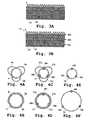
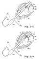
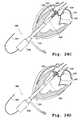
- FIG. 1Ais a perspective view of one embodiment of a valve prosthesis support frame with a plurality of claspers.
- FIG. 1Bis a perspective view of one embodiment of a valve prosthesis support frame with a plurality of valve claspers.
- FIG. 1Cis a perspective view of one embodiment of a valve prosthesis support frame.
- FIG. 1Dis a perspective view of one embodiment of a valve prosthesis support frame in a partially expanded condition.
- FIG. 1Eis a top view of one embodiment of a valve prosthesis support frame with a plurality of valve claspers.
- FIGS. 2A and 2Billustrate a perspective view of a plurality of valve claspers with detents.
- FIG. 3Aillustrates a valve prosthesis support frame in a flat form with a plurality of valve claspers and a covering.
- FIG. 3Billustrates a valve prosthesis support frame in a flat form with a plurality of valve claspers, engagement fasteners and a covering.
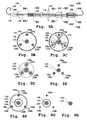
- FIGS. 4A-4Dillustrate a top view of a valve prosthesis support frame with movably connected claspers in which the support frame is in a compact ( FIGS. 4A and 4C ) or an expanded ( FIGS. 4B and 4D ) condition.
- FIGS. 4E and 4Fillustrate a top view of a valve prosthesis support frame with engagement fasteners in a compact ( FIG. 4E ) or expanded ( FIG. 4F ) condition.
- FIG. 5Ais a transverse view of a valve clasper movably connected to a prosthetic valve support frame structure in its compact condition in situ, wherein an apex member connects a leg member and a u-shaped member.
- the valve clasperis in an engagement position.
- FIG. 5Bis a transverse view of a valve clasper movably connected to a prosthetic valve support frame structure in its compact condition in situ, wherein an apex member connects a leg member and a u-shaped member.
- the valve clasperis in an nested position.
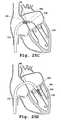
- FIG. 5Cis a transverse view of a valve clasper movably connected to a prosthetic valve support frame structure in the expanded condition in situ, wherein an apex member connects a leg member and a u-shaped member.
- FIG. 5Dis a transverse view of a valve clasper movably connected to a prosthetic valve support frame structure having engagement fasteners and in its compact condition in situ.
- the valve clasperis in an engagement position.
- FIG. 5Eis a transverse view of a valve clasper movably connected to a prosthetic valve support frame structure having engagement fasteners and in its compact condition in situ.
- the valve clasperis in a nested position.
- FIG. 5Fis a transverse view of a valve clasper movably connected to a prosthetic valve support frame structure having engagement fasteners and in the expanded condition in situ.
- FIG. 5Gis a transverse view of one embodiment of a valve clasper movably connected to a prosthetic valve support frame structure in its compact condition in situ.
- the valve clasperis in an engagement position.
- FIG. 5His a transverse view of one embodiment of a valve clasper movably connected to a prosthetic valve support frame structure in its expanded condition in situ.
- the valve clasperis in a nested position.
- FIG. 5Iis a transverse view of one embodiment of a valve clasper movably connected to a prosthetic valve support frame structure in its compact condition in situ.
- FIG. 5Jis a transverse view of one embodiment of a valve clasper movably connected to a prosthetic valve support frame structure in its compact condition in situ.
- the valve clasperis in an engagement position.
- FIG. 5Kis a transverse view of one embodiment of a valve clasper movably connected to a prosthetic valve support frame structure in its expanded condition in situ.
- the valve clasperis in a nested position.
- FIG. 5Lis a transverse view of one embodiment of a valve clasper movably connected to a prosthetic valve support frame structure in its compact condition in situ.
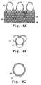
- FIG. 6Aillustrates a valve prosthesis support frame in a flat form with a plurality of valve claspers fixed to the support frame, a plurality of prosthetic leaflet suture lines and a covering.
- FIG. 6Billustrates the top view of a valve prosthesis support frame with a plurality of valve claspers in which the plurality of valve claspers are fixed to the support frame and the valve prosthesis support frame is in its compact condition.
- FIG. 6Cshows the top view of a valve prosthesis support frame with a plurality of valve claspers in which the plurality of valve claspers are fixed to the support frame and the valve prosthesis support frame is in its expanded condition.
- FIG. 7Ashowed a valve prosthesis with a sheath in situ wherein the support frame is in a compact condition and the valve claspers are in a nested position.
- FIG. 7Billustrates a prosthetic valve with movably connected claspers deployed in a native cardiac valve.
- FIGS. 8A-8Hare schematic illustrations of one embodiment of an implantation device and a method for implanting a valve prosthesis in a native valve of a heart.
- FIG. 9A-9Qprovides more detailed views of one embodiment of an implantation device including cross-sectional views showing the placement of the various implantation device components within the implantation device.
- FIGS. 10A-10Cillustrate various embodiments for connecting track wires to valve claspers.
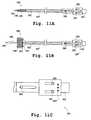
- FIGS. 11A-11Billustrate one embodiment of a valve prosthesis implantation device with control unit, wherein the valve prosthesis is both in a compact condition ( FIG. 11A ) and an expanded condition ( FIG. 11B ).
- FIG. 11Cillustrates one embodiment of an implantation device control unit.
- FIG. 12Aillustrates one embodiment of a valve prosthesis implantation device.
- FIGS. 12B-12Dprovide cross-sectional views of one embodiment of a valve prosthesis implantation device.
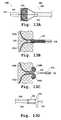
- FIGS. 13A-13Dprovide detailed view of one embodiment of an implantation device.
- FIGS. 14A-14Dillustrate manipulation steps for one embodiment of an implantation device.
- FIGS. 15A-15Cillustrate manipulation steps for one embodiment of an implantation device.
- FIGS. 16A-16Cillustrate an alternative embodiment for a valve prosthesis support frame.
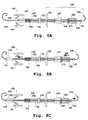
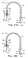
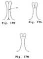
- FIGS. 17A-17Billustrate alternative embodiments for clasper multiplex units.
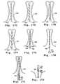
- FIGS. 17C-17Gillustrate alternative embodiments for the leg members of clasper multiplex units.
- FIGS. 17H-17Millustrate alternative embodiments for attachment and release clasper multiplex unit leg members.
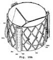
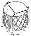
- FIGS. 18A-18Billustrate alternative embodiments for a clasper multiplex unit.
- FIG. 18Cillustrates an alternative embodiment for a clasper multiplex unit leg member.
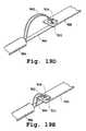
- FIGS. 19A-19Eillustrate an alternative embodiment for reversible attachment of a valve implantation device to a leg member of a clasper multiplex unit.
- FIGS. 20A-20Cillustrate an alternative embodiment for release of a valve delivery device from a leg member of a clasper multiplex unit.
- FIGS. 21A-21Cillustrate an alternative embodiment for reversible attachment of a valve delivery device to a leg member of a clasper multiplex unit.
- FIGS. 22A-22Dillustrate an alternative embodiment for release of a valve delivery device from a leg member of a clasper multiplex unit.
- FIG. 23illustrates an introducer inserted in the thoracoabdominal region.
- FIGS. 24A-24Hare schematic illustrations of a transapical procedure for aortic valve replacement.
- FIGS. 25A-25Lare schematic illustrations of an alternative embodiment for an implantation device and a method for implanting a mitral valve prosthesis in a native mitral valve of a heart.
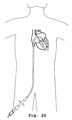
- FIG. 26illustrates a path for delivery of a prosthetic heart valve which includes advancing an implantation device through the inferior vena cava.
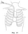
- FIG. 27illustrates a path for delivery of a prosthetic heart valve which includes introducing an implantation device into the jugular vein and advancing the device through the superior vena cava.
- FIG. 28illustrates a path for delivery of a prosthetic pulmonary valve which includes an implantation device into the jugular vein and advancing the device through the superior vena cava.
- FIGS. 29A-29Hillustrates a method of using one embodiment of an implantation device for implanting a prosthetic aortic valve which includes advancing the implantation device through the femoral artery and aortic arch.
- FIGS. 30A-30Cillustrate an alternative embodiment for a method of delivering and deploying a valve prosthesis.
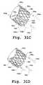
- FIGS. 31A-31Dillustrates a method for deploying and disconnecting from a prosthetic valve.
- the present disclosureprovides devices, systems and methods for valve replacement, preferably using a minimally invasive surgical technique. While the devices and methods will have application in a number of different vessels in various parts of the body, they are particularly well-suited for replacement of a malfunctioning cardiac valve, and in particular an aortic valve, a pulmonary valve or a mitral valve.
- the devices and methodsare particularly advantageous in their ability to provide a more flexible prosthetic heart valve implantation device, ensure accurate and precise placement of the prosthetic heart valve with reduced reliance on imaging, and provide additional anchoring of the prosthetic valve, reducing the incidence of valve migration. Another advantage is the delivery and implantation of a sutureless valve prosthesis as described herein.
- the present disclosurealso provides improved devices and methods for implanting a prosthetic heart valve.
- improved minimally invasive methods and devicesare provided for antegrade, percutaneous or femoral transcatheter implantation of expansible prosthetic heart valves within or adjacent a valved anatomic site within the heart.
- the improved prosthetic heart valve devices and methods of the present disclosureprovide more flexibility in the valve replacement procedure, ensure accurate and precise placement of the prosthetic heart valve with reduced reliance on imaging, and provide additional anchoring of the prosthetic valve, reducing the incidence of valve migration or misalignment.
- One method for deploying an aortic valvegenerally comprises inserting a valve delivery system between the ribs of the patient or subject into the apex of the left ventricle, then delivering the valve prosthesis to the site of the patient's diseased valve (transapical delivery).
- Another method of deploying the aortic valvegenerally comprises gaining access to the aorta through the femoral artery (femoral delivery).
- Another method for deploying a pulmonary or a mitral valvegenerally comprises inserting a valve delivery system into the jugular vein, then guiding the system through the superior vena cava into the right atrium.
- the devicecan then be advanced into the right ventricle and to the pulmonary valve.
- the devicecan be advanced via transeptal puncture into the left atrium, then advanced to the mitral valve.
- Yet another method for deploying a pulmonary or a mitral valvegenerally comprises inserting a valve delivery system into the femoral vein, then guiding the system through the superior vena cava into the right atrium, and advancing the device to the pulmonary or mitral valve as described above.
- the valve delivery system or implantation deviceis of sufficient size and length to pass through a first opening in a patient's body (e.g., an aorta or a femoral artery or vein access point), through a patient's aorta, femoral artery or vein.
- the implantation devicemay alternatively enter through a transthoracic port which provides access through the patient's thoracoabdominal (e.g., intercostal) region and into the left ventricle at or near the apex.
- the transthoracic portaccording to various exemplary embodiments is one of an introducer, trocar, or cannular, as is generally known in the art.
- At least one delivery sheath or catheteris advanced along a guidewire through and past the aortic, mitral or pulmonary valve.
- the access portincludes one or more hemostasis valves or seals.
- the hemostasis valve or sealis adapted to provide a blood tight seal against blood loss or leakage during the procedure, and can be used at the apex, at the aorta, or in both locations.
- the portis configured to allow passage of the implantation device, catheter, or any tools or devices to be delivered to the target site using the implantation device, while at the same time providing a blood tight seal against blood loss or leakage. Such methods are well known to those having ordinary skill in the art.
- the devices and methods described hereinmay be used with subjects including humans and other mammals, including but not limited to rats, rabbits, pigs, dogs, sheep and horses.
- a valve prosthesis 2which in a preferred embodiment is a prosthetic heart valve, is provided.
- the valve prosthesisis configured to be placed in a native diseased valve of a subject, such as a native stenotic aortic, pulmonary or mitral valve, using a minimally-invasive approach such as a beating heart transapical procedure, or a retrograde transaortic procedure.
- a minimally-invasive approachsuch as a beating heart transapical procedure, or a retrograde transaortic procedure.
- the sutureless prosthetic heart valvecomprises a self-expanding support frame, prosthetic valve leaflets (not shown in FIG. 1A ) and one or more valve claspers.
- the valve claspersmay be positioned serially or concentrically with the support frame. Both the support frame and the valve claspers can be made from a shape memory material such that they can be compressed to a radius which allows delivery through, for example, arteries and veins, then expanded as needed for deployment and placement of the valve in the appropriate position.
- valve claspersare movably connected to the support frame such that the valve claspers may be moved from a proximal or distal position from the support frame to a concentric position with the support frame.
- the distance from which the valve claspers may be serially displaced from the support frameis highly variable, such that the valve claspers may be adjacent to the support frame, or potentially inches or feet away from the support frame during the delivery procedure.
- no part of the valve claspersare physically fixed to the support frame, such as by welding or otherwise adhering.
- movably connectedit is understood that while two structural elements may be in physical contact at any given time, they are not irreversibly connected or attached, such as by welding or through an adhesive.
- the valve claspersafter deployment of the prosthetic valve as described herein, while the valve claspers are in physical contact with the prosthetic valve support frame, the valve claspers are able to move longitudinally with respect to the support frame. Also, portions of the valve clasper can move radially from the support frame. Regardless, the valve claspers remain movably connected to the support frame.
- the valve clasperscan freely move along the longitudinal axis in either a proximal or distal direction.
- the valve claspersare movably connected to the support frame in a manner that prevents the entire valve clasper from being radially displaced from the support frame, however, portions of the valve clasper can be radially displaced from the support frame as needed.
- the valve claspersWhen the support frame is deployed or expanded within the native heart valve, the valve claspers become sandwiched between the support frame and the native valve tissue, becoming at least partially, and may be fully immobilized. The valve claspers also function to hold the deployed prosthetic valve in place within the native valve.
- the valve prosthesiscomprises a support frame (e.g., a stent frame) 4 which comprises an outer surface 7 and defines a central orifice 9 about an axis (the longitudinal axis denoted by dashed line 11 in FIG. 1A ) along an inflow-outflow direction.
- the support frameis radially expandable between a compact or compressed condition and an expanded or deployed condition.
- the support framecan be a lattice design which can have different shapes, including but not limited to, diamond and oval shape.
- a support framemay have additional features, such as a plurality of flex-links 18 as shown in support frame 16 depicted in FIG. 1C .
- Design of the support frame with the plurality of flex linksallows expansion of a portion of the valve support frame as illustrated in FIG. 1D .
- the support framecan be self-expanding.
- the self-expanding support framecan be comprised of a shape-memory metal which can change shape at a designated temperature or temperature range.
- the self-expanding framescan include those having a spring-bias.
- the material from which the support frame is fabricatedallows the support frame to automatically expand to its functional size and shape when deployed but also allows the support frame to be radially compressed to a smaller profile for delivery through the patient's vasculature.
- suitable materials for self-expanding framesinclude, but are not limited to, medical grade stainless steel, titanium, tantalum, platinum alloys, niobium alloys, cobalt alloys, alginate, or combinations thereof.
- shape-memory materialsinclude shape memory plastics, polymers, and thermoplastic materials which are inert in the body. Shape memory alloys having superelastic properties generally made from ratios of nickel and titanium, commonly known as Nitinol, are preferred materials.
- FIGS. 1C-1DAn alternative embodiment of the support frame is illustrated in FIGS. 1C-1D .
- support frame 16has a plurality of flexible links 18 .
- the presence and arrangement of flexible links 18allows the portion of the support frame on one side of the flexible links to expand or compress independently of the portion on the other side of the flexible links, as depicted in FIG. 1D .
- the functional significance of this structural featureis described in further detail below.
- the support frameis not self-expanding, and may be expanded, for example, using a balloon catheter as is well known in the art.
- valve prosthesisfurther comprises at least one valve clasper, such as valve clasper 6 which is illustrated in FIG. 1A .
- Valve claspersmay alternatively be referred to as sinus locators, valve positioners, or valve hangers.
- valve claspersare comprised of a shape-memory metal.
- the shape memory alloyis Nitinol.
- the at least one valve clasper 6is movably connected to the valve support frame 4 .
- the at least one valve clasper 6is movably connected to the valve support frame 4 when the valve support frame 4 is in a compact condition prior to delivery and deployment.
- the at least one valve clasper 6is not fixed to the valve support frame 4 . It is understood that each valve clasper of a valve prosthesis described herein is separate from the valve support frame.
- valve claspere.g., the leg member
- the valve claspermay be in contact with or otherwise reversibly attached or connected to the valve support frame
- no part of the valve clasperis fixed, e.g., welded or otherwise irreversibly adhered, to the valve support frame.
- the valve clasperwhich may be in contract with or otherwise reversibly attached to the valve support frame, is not irreversibly fixed to the valve support frame.
- the at least one valve clasperis comprised, in one embodiment, of a u-shaped member 8 and two leg members, such as leg member 10 which is representative.
- each of two leg members 10 of the valve clasperis positioned approximately parallel to the longitudinal axis of the support frame and is attached to u-shaped member 8 by an apex 5 .
- each of the two leg members of the valve clasperhas a first and second end, wherein each of the first ends of the two leg members are joined to the to u-shaped member 8 .
- An apex 5is present between each leg and the u-shaped member.
- an apexe.g., apex 5
- a vertexis defined as a vertex formed by the joining of u-shaped member 8 and one leg member 10 .
- the vertexis curved.
- the vertexis curved such that two leg members 10 are approximately parallel to each other.
- the second ends of the two leg membersare free ends.
- the second terminus or end of one or more of the leg membersterminates in a detent 12 (also referred to as a foot or barb), as shown in FIG. 2A .
- Detent 12may be made of a shape memory alloy such as nitinol.
- the detentsare oriented parallel to a longitudinal axis of the valve prosthesis, while for other applications, the detents are oriented to form an angle with respect to the longitudinal axis.
- the detentsmay be approximately parallel to the longitudinal axis of the valve prosthesis support frame in the compact position and/or when the valve prosthesis is encased in a sheath.
- the detentsmay form an angle with respect to the longitudinal axis of the valve prosthesis or a leg member when the valve prosthesis is in an expanded condition.
- the detentscan have varying lengths.
- the leg membersmay have, for example, a zig-zag or coiled shape after deployment of the valve prosthesis. The detents help to secure the valve claspers to the valve support frame after the valve prosthesis is deployed in the native valve.
- the support framehas a length L and the leg members are at least L in length. In other embodiments, the leg members are equal to or less than length L.
- the shape of the member joining the two leg membersis not limited to being a u-shape.
- the u-shaped membermay have other shapes including, but not limited to, rectangle, square, diamond, triangle, oval, circle, or a combination of these shapes.
- the u-shaped membermay be of any shape that allows it to engage and/or rest against the floor of the native valve sinus or adjacent to the commissure of the native valve leaflets.
- the at least one valve clasperis movable along the longitudinal axis of the support frame.
- the valve clasperWhen the valve clasper is off-set from the support frame, e.g., when the u-shaped member of the valve clasper is in a position distal to the proximal end of the support frame and/or does not approximately fully overlap with the support frame, this position is referred to as the engagement position.
- u-shaped member 8 of a valve claspermay extend radially from a leg member and the longitudinal axis of support frame 4 in its compact condition.
- clasper apex 5is approximately adjacent to the distal end of support frame 4 .
- the valve clasperis in its nesting position when at least a portion of the u-shaped member is in contact or adjacent to the floor of a native sinus or the commissures of the native leaflets of the valve.
- a leg membersuch as leg member 10
- a valve claspersuch as valve clasper 6
- this positionis referred to as the nesting position.
- a valve prosthesis 20comprises valve support frame 22 and a central orifice 32 .
- Support frame 22is radially expandable between a compact condition and an expanded condition.
- Support frame 22has an outer or external surface 30 and defines a central orifice 32 about an axis (the longitudinal axis denoted by dashed line 34 in FIG. 1B ).
- the longitudinal axiscorresponds to the inflow-outflow axis.
- the valve prosthesisfurther comprises a plurality of prosthetic valve leaflets (not shown in FIG. 1B ).
- valve prosthesis 20further comprises at least one valve clasper 24 .
- At least one valve clasper 24comprises a u-shaped member 26 .
- the u-shaped member 26has a curved portion at its proximal end connected to two straight portions, e.g., 28 , each ending in a free end, as seen in FIG. 1B .
- valve clasper 24remains straight following deployment of valve prosthesis 20 .
- at least part of the straight portion of the at least one valve clasper 24which may be made of a shape memory material, may have, for example, a zig-zag or coiled shape after deployment of valve prosthesis 20 as shown in FIG. 2B for clasper 6 .
- the at least one valve clasper 24is movably connected to support frame 22 and movable along the longitudinal axis of support frame 22 .
- valve clasper 24When valve clasper 24 is off-set from the support frame, e.g., when the free ends of valve clasper 24 are in a position proximal to the proximal end of support frame 22 and/or when valve clasper 24 does not fully overlap with the support frame, this position is referred to as the engagement position. In this position, at least one u-shaped member 26 of valve clasper 24 may extend radially from the longitudinal axis of support frame 22 in its compact condition.
- valve clasper 24In situ, when valve clasper 24 is in the nesting position, at least a portion of at least one u-shaped member 26 is in contact with or adjacent to the floor of a native sinus or adjacent to the native valve commissure.
- the plurality of valve claspers 6 or 24 movably connected to support frame 4 or 22 , respectivelycan be two, three, four, five, or more valve claspers, to accommodate different valve replacement procedure or according to the anatomical structure of the native valve that is to be replaced.
- the number of valve claspers in the valve prosthesisis three.
- the plurality of valve claspers 6 movably connected to support frame 4can be joined to generate a single valve clasper comprising multiple u-shaped members 8 and multiple leg members 10 .
- the valve prostheses 2 and 20can further comprise a plurality of prosthetic valve leaflets having surfaces defining a reversibly sealable opening for unidirectional flow of a liquid through the prosthetic valve.
- the prosthetic valvecan include three valve leaflets for a tri-leaflet configuration.
- mono-leaflet, bi-leaflet, and/or multi-leaflet configurationsare also possible.
- the valve leafletscan be coupled to the valve frame so as to span and control fluid flow through the lumen of the prosthetic valve.
- the leafletscomprise synthetic material, engineered biological tissue, biological valvular leaflet tissue, pericardial tissue, cross-linked pericardial tissue, or combinations thereof.
- the pericardial tissueis selected from but not limited to the group consisting of bovine, equine, porcine, ovine, human tissue, or combinations thereof.
- Prosthetic valve leafletsmay be sewed onto valve support frame 4 or 22 along a leaflet suture line, e.g. suture line 19 as shown in FIG. 3A , which is a rolled-out view of a support frame.
- valve leafletsare fixed onto support frame 4 or 22 by other comparable methods understood by those with ordinary skill in the art.
- the support frame of valve prosthesis 2 or 20is at least partially covered by a covering. This is depicted in FIG. 3A for a support frame 4 of valve prosthesis 2 , wherein the support frame is covered by a covering (graft covering) 15 .
- a coveringgraft covering
- Any suitable lightweight, strong, fluid impervious, biocompatible materialmay be utilized.
- the coveringmay be attached in any suitable manner and by any suitable means.
- the coveringmay be reversibly attached or permanently attached to the support frame.
- the coveringmay be positioned on the external and/or internal surface of the valve prosthesis support frame.
- the coveringmay be attached to the frame utilizing sutures, staples, chemical/heat bonding and/or adhesive.
- the coveringis a fabric.
- the fabricis comprised of, for example, a material identified by a tradename selected from Nylon®, Dacron®, or Teflon®, or is expanded polytetrafluoroethylene (ePTFE), and/or other materials.
- the coveringcan further include a sealing material.
- the sealing materialcan be selected from the general class of materials that include polysaccharides, proteins, and biocompatible gels. Specific examples of these polymeric materials can include, but are not limited to, those derived from poly(ethylene oxide) (PEO), poly(ethylene glycol) (PEG), poly(vinyl alcohol) (PVA), poly(vinylpyrrolidone) (PVP), poly(ethyloxazoline) (PEOX) polyaminoacids, pseudopolyamino acids, and polyethyloxazoline, as well as copolymers of these with each other or other water soluble polymers or water insoluble polymers.
- PEOpoly(ethylene oxide)
- PEGpoly(ethylene glycol)
- PVApoly(vinyl alcohol)
- PVPpoly(vinylpyrrolidone)
- PEOXpoly(ethyloxazoline)
- polysaccharideexamples include those derived from alginate, hyaluronic acid, chondroitin sulfate, dextran, dextran sulfate, heparin, heparin sulfate, heparan sulfate, chitosan, gellan gum, xanthan gum, guar gum, water soluble cellulose derivatives, and carrageenan.
- proteinsinclude those derived from gelatin, collagen, elastin, zein, and albumin, whether produced from natural or recombinant sources.
- the materialscan be bioactive agents, including those that modulate thrombosis, those that encourage cellular ingrowth, through-growth, and endothelialization, those that resist infection, and those that reduce calcification.
- the coveringmay be on the inside and/or outside surface of the support frame, and may be disposed to partially cover the support frame or to fully cover the support frame.
- At least a portion of at least one leg member 10 of valve clasper 6is positioned between support frame 4 and the covering on the surface of support frame 4 .
- the coveringcan function at least in part to movably connect valve clasper 6 to support frame 4 .
- the at least one leg member 10 fixed at a first end to the at least one u-shaped member 8are movable parallel to longitudinal axis 11 , wherein at least a portion or substantially of the at least one leg member 10 can be positioned between the covering and support frame 4 .
- the curved portion of the u-shaped member 26 of valve clasper 24 and/or a part of straight portion 28is positioned between support frame 22 and the covering on the surface of the support frame.
- the coveringcan function at least in part to movably connect valve clasper 24 to support frame 22 .
- the two straight portions of the valve clasper 24is movable parallel to longitudinal axis 32 , wherein at least a portion or substantially of the valve clasper is positioned between the covering and support frame.
- support frame 4 or 22may be coated with a material which promotes and/or supports tissue growth in the region in which the valve prosthesis is deployed.
- the material which promotes and/or supports tissue growthmay be imbedded or incorporated in the covering.
- a support frame 14further comprises a plurality of engagement fasteners, such as fastener 46 .
- the engagement fastenerscan be directly fixed on the support frame or can be manufactured as part of the support frame.
- Each set of engagement fastenersare formed by several engagement fasteners that are arranged linearly along the longitudinal axis of the support frame.
- Each engagement fastenermay be a half circle shape, with the open side facing opposite directions in alternating engagement fasteners within each set of engagement fasteners.
- the leg members of the valve claspersare inserted through the openings formed by each set of engagement fasteners.
- FIGS. 3A and 3Balso illustrate an embodiment wherein the support frame is covered with a covering 15 .
- the support frame of prosthetic valveis initially in a compact condition.
- the valve clasper(s)which is/are also compact (not radially extending from the support frame), is/are movable between an engagement position and a nesting position
- the valve clasper(s) during valve deliveryis/are in an engagement position where the valve clasper(s) is/are positioned distally or proximally from the support frame.
- the valve clasperssuch as valve claspers 6 a , 6 b , 6 c in FIG. 4A , are moved to an open or expanded condition, for contact with and seating into a sinus of a native heart valve.
- FIGS. 4A and 4BSupport frame 4 as shown in FIGS. 4A and 4B is then moved to an expanded condition.
- a plurality of valve claspers 6 a , 6 b , 6 c movably connected to the support frame in the compact conditionare shown in FIG. 4A as viewed from the top.
- FIG. 4Bshows the plurality of valve claspers with support frame 4 in its expanded condition.
- FIG. 4Cshows a support frame 14 having engagement fasteners 46 a , 46 b , 46 c wherein the support frame 14 is in a compact condition and the u-shaped members of valve claspers 47 a , 47 b , 47 c are in an open or expanded condition for contact with and seating into a sinus of a native heart valve.
- FIGS. 4E and 4Fshow support frame 14 having engagement fasteners 46 a , 46 b , 46 c , wherein support frame 14 is in a compact condition ( FIG. 4E ) and an expanded condition ( FIG. 4F ).
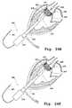
- FIG. 5Aillustrates a valve clasper 6 movably attached to support frame 4 relative to a native heart valve leaflet 30 .
- valve clasper 6is movable from an engagement position ( FIG. 5A ) to a nesting position ( FIG. 5B ), where valve clasper 6 is in a nested or concentric arrangement with the support frame, and wherein u-shaped member 8 approximately contacts the sinus (e.g., aortic, mitral or pulmonary sinus) of the native heart leaflet 30 (see FIG. 5B ).
- sinuse.g., aortic, mitral or pulmonary sinus
- a prosthetic leaflet 36is attached to support frame 4 and extends into the orifice of the prosthetic valve, to provide in conjunction with one or more additional prosthetic leaflets (not shown), a one-way valve in the orifice.
- FIG. 5Cafter support frame 4 is radially enlarged to an expanded condition, at least a portion of native valve leaflet 30 is sandwiched between u-shaped member 8 and support frame 4 .
- covering 15also shown in FIGS. 5A-5C is covering 15 , which in some embodiments, may function in part to hold the leg member adjacent to the support frame.
- FIGS. 5D-5Fshow support frame 14 with engagement fasteners 46 a , 46 b , 46 c , wherein the valve clasper is above the native valve sinus and in an engagement position ( FIG. 5D ), the valve clasper has moved toward the valve sinus to allow u-shaped member 11 to contact the native valve sinus ( FIG. 5E ) and support frame 14 has expanded radially so that at least a portion of native valve leaflet 30 is sandwiched between u-shaped member 11 and support frame 14 ( FIG. 5F ).
- valve clasper 24is movably connected to support frame 22 .
- valve clasper 24in an engagement position, is above the native valve and is radially expanded from support frame 22 .
- valve clasper 24is movable from an engagement position ( FIG. 5G ) to a nesting position ( FIG. 5H ), where valve clasper 24 is in a nested or concentric arrangement with the support frame, and wherein u-shaped member 26 approximately contacts the sinus of native heart leaflet 30 .
- FIG. 5Gvalve clasper 24 in an engagement position, is above the native valve and is radially expanded from support frame 22 .
- FIG. 5Ha nesting position
- valve clasper 24is in a nested or concentric arrangement with the support frame, and wherein u-shaped member 26 approximately contacts the sinus of native heart leaflet 30 .
- support frame 22is then radially enlarged to an expanded condition so that at least a portion of native valve leaflet 30 is sandwiched between valve clasper 24 and support frame 22 .
- support frame covering 15also shown in FIGS. 5G-5I is support frame covering 15 , which in some embodiments, may function in part to properly position the valve clasper relative to the support frame.
- valve clasper 71is fixed (e.g., adhered to or welded to) a support frame 73 of a valve prosthesis.
- FIG. 5Jis a transverse view showing the valve prosthesis with fixed clasper 71 in an engagement position above the native valve.
- FIG. 5Kthe valve prosthesis is moved to a nesting position, while in FIG. 5L , support frame 73 is expanded radially to an expanded condition, and valve clasper 71 is sandwiched between the native valve leaflet and support frame 73 .
- valve clasper 71which is representative
- FIGS. 6A-6CThe alternative embodiment, wherein the plurality of valve claspers, such as valve clasper 71 which is representative, are fixed to the support frame 44 of the valve prosthesis, is shown in FIGS. 6A-6C .
- each valve clasperis directly fixed to the support frame, for example, by welding.
- the valve claspersare manufactured as part of support frame 44 .
- the valve prosthesis, shown in FIG. 6A in a rolled out view,also shows a line 47 at which prosthetic heart valves are secured to the support frame, and an optional covering 48 on the support frame.
- FIG. 6Bis a top view of valve support frame 44 with valve clasper 71 wherein valve clasper 71 is permanently fixed to the support frame and wherein support frame 44 is in a compact condition.
- FIG. 6Cshows the same valve support frame with clasper in which the support frame is in an expanded condition.
- FIGS. 7A and 7Billustrate a sutureless valve prosthesis with movably connected claspers in situ.
- support frame 90is in a compact condition and encased by sheath 96
- valve claspers 92are in a nested position prior to radial expansion of the support frame within the native valve.
- a portion of the implantation deviceis shown as 96 .
- the engaging portion of the valve claspere.g., the u-shaped member or curved portion, has contacted, or engaged, the native valve sinus.
- FIG. 7Bshows the same valve in which the support frame is in its expanded condition, after valve delivery and deployment and after removal of a valve delivery device.
- Native heart valve leaflets 94are sandwiched between the valve claspers and the support frame to facilitate anchoring of the valve prosthesis in the heart annulus. It is understood that the positioning of the support frame in which native heart valve leaflets are sandwiched between valve claspers of a valve prosthesis and the prosthesis support frame is applicable to all coronary valves (i.e., aortic, pulmonary, tricuspid and mitral). It is understood that in some embodiments, the number of valve claspers will equal of the number of native leaflets within the native valve being treated.
- valve prostheses as described hereinmay be used in various aspects of implantation devices described herein or in any method or device known by one with ordinary skill in the art to implant a valve prosthesis into a subject.
- Implantation Devices for Delivery of a Prosthetic Aortic, Pulmonary or Mitral ValveII. Implantation Devices for Delivery of a Prosthetic Aortic, Pulmonary or Mitral Valve
- an implantation device for delivery of a valve prosthesisis provided.
- the implantation deviceis comprised of a valve prosthesis, such as valve prosthesis 2 described above, and a delivery device, now to be described.
- implantation device 100is designed, for example, for apical (antegrade) delivery of an aortic heart valve prosthesis, percutaneous delivery of a pulmonary valve prosthesis through the superior vena cava, or delivery of a mitral valve prosthesis or pulmonary valve prosthesis through the inferior vena cava.
- Implantation device 100is designed for apical delivery of an aortic heart valve prosthesis.
- Implantation device 100includes a control unit, generally indicated in FIG. 8A by 250 , and in one embodiment comprises several separate and independent controllers, described below.
- Delivery device 100comprises a first sheath 120 which fully or partially encases a prosthetic valve support frame, e.g., support frame 102 , in a compact condition and a second sheath 130 which is located distal to first sheath 120 and encases at least one valve clasper, e.g., valve clasper 106 .
- delivery device 100further comprises a track wire controller 200 (alternatively called a track cable controller) which is located proximal to first sheath 120 .
- delivery device 100further comprises at least one track wire 150 (alternatively called a track cable) which extends distally from track wire controller 200 and may contact the proximal ends of the valve clasper leg members.
- track wire controller 200comprises at least one release switch 210 which is attached to the proximal end of the at least one track wire.
- delivery device 100does not have a second sheath.
- the delivery deviceis designed with a hollow center to allow insertion of a guidewire 110 along which the delivery device may be advanced for delivery of the valve prosthesis.
- First sheath 120is cylindrical in shape and is hollow.
- the first sheathmay be straight or curved.
- the length and flexibility of the first sheathwill vary according to the delivery method as would easily be understood by a skilled artisan.
- Delivery of the valve prosthesis through the femoral arteryrequires a flexible sheath which is long enough to extend from the point of entry to the native valve in need of treatment.
- Second sheath 130is hollow and is mostly cylindrical in shape.
- the distal portion of second sheath 130may have different shapes, such as a curved cone, or a pointed tip.
- the distal end of second sheath 130has an opening through with a guidewire may pass.
- the at least one track wire 150is in contact with at least one valve clasper 106 such that the distal end of the at least one track wire 150 contacts the free end of a leg member 107 of valve clasper 106 (see FIGS. 9J-9L ).
- track wire 150is hollow to permit, for example, insertion of one or more other cables or wires.
- hollow track wire 150encases a locking wire 220 , seen best in FIG. 9J-9L , that extends from the approximately proximal end of the control unit to the approximately distal end of a track wire 150 .
- the locking wireis fixed at its proximal end to a locking wire support 190 ( FIG. 9M ).
- the locking wirecomprises a locking member 230 at its distal end ( FIG. 9L ).
- track wire 150encases two of leg members, for example 107 a and 107 b in FIGS. 9K-9L , of two different, independent valve claspers 106 and locking wire 220 .
- this arrangement of leg members and a locking wire having a locking memberresults in a friction fit of the components within the track wire, thus securing leg members of two different valve claspers within a hollow track wire as long as the locking member of the locking wire is adjacent to two leg members at approximately the distal end of the track wire.
- each of the track wiressuch as track wire 150
- the proximal ends of each of track wire 150may be welded or glued to the various components of the control unit.
- the proximal ends of track wire 150may each be wound around or threaded through the various components to allow greater flexibility with respect to the lengths of track wire 150 .
- valve prosthesis support frameis at least partially covered by a covering and a track wire is disposed between the support frame and the covering, to movably secure the track wire to one or more valve claspers and the support frame.
- the delivery devicefurther comprises a valve prosthesis pusher wire 170 (alternatively called a pusher cable) having a proximal end fixed to the control unit and a distal end for contact with the proximal end of valve prosthesis 102 .
- the details of various embodiments of the pusher wireare presented in FIGS. 9M-9Q .
- the implantation devicemay comprise one, two, three, four or more valve prosthesis pusher wires.
- the control unit of the implantation devicefurther comprises a pusher wire controller 165 (alternatively called a pusher cable controller).
- the approximately proximal end of the valve prosthesis pusher wire 170is fixed to pusher wire controller 165 .
- the pusher wireextends from the approximately proximal end of the valve prosthesis proximally to the pusher wire controller.
- the valve prosthesis pusher wiremay be hollow or solid and may be made of wire, plastic or other suitable materials.
- the implantation devicecomprises a pusher wire support member which extends longitudinally and distally from the pusher wire controller.
- the pusher wire support membermay vary in length and functions to allow the user to apply pressure in a distal direction to the proximal end of the valve prosthesis, using the pusher wire controller.
- the pusher wire support memberis cylindrical in shape with a longitudinal axis parallel to that of the first sheath.
- the pusher wire support memberis hollow.
- At least one pusher wireis located on the external side of the pusher wire support member. In an alternative embodiment, the at least one pusher wire is located on the internal surface of the pusher wire support member. In a further embodiment, at least a portion of valve prosthesis pusher wire 170 is secured along its length to the pusher wire support member. This embodiment is shown in FIGS. 8F-8H The pusher wire support is fixed at its proximal end to pusher wire controller 165 .
- valve prosthesis pusher wire 170terminates in a pusher wire engager 175 , for reversibly engaging the proximal end of the valve prosthesis.
- valve prosthesis engaging membermay comprise a variety of configurations, for example, those illustrated in FIGS. 9O-9Q , and may comprise, for example, one, two, three or more prongs.
- each of pusher wiresare fixed to, for example, the control unit or pusher wire controller 165 .
- the proximal ends of each of pusher wiresmay be welded or glued to the various components of the control unit.
- the proximal ends of pusher wiresmay each be wound around or threaded through the various components to allow greater flexibility with respect to the lengths of pusher wires.
- the implantation devicecomprises a second sheath 130 and a second sheath control cable 140 (central control cable) attached at its distal end to the second sheath.
- second sheath 130can take the form of a nose cone and is disposed distal to the first sheath.
- a second sheathis concentric with the first sheath are contemplated.
- the distal end of second sheath control cable 140may be attached to the proximal or distal end of second sheath 130 or at a position between the proximal and distal ends of second sheath 130 .
- second sheath control cable 140is fixed to a second sheath controller 135 .
- the second sheathencases each of the plurality of valve claspers, e.g., valve claspers 106 , in a compact condition.
- the second sheath controllerfunctions to allow the user to move the second sheath in a proximal or distal direction independent of parts of the delivery device which are not fixed to the second sheath.
- the control unitallows the user to independently control various elements of the implantation device as described herein and shown in FIGS. 8A-8H .
- the control unitcomprises a track wire control unit 200 to provide for independent control by a user of track wire 150 .
- the one or more track wires in the deviceis attached at its proximal end to the track wire control unit.
- the distal end of at least one track wire 150can form a contact with a leg member of valve clasper 106 .
- Track wire control unit 200comprises at least one release switch, such as release switch 210 , and the at least one track wire is fixed at approximately its proximal end to the at least one release switch.
- implantation device 100comprises two track wires, each attached at its proximal end to a release switch, such as track wire 150 fixed at its proximal end to release switch 210 .
- implantation device 100comprises three track wires, each attached at its proximal end to a release switch.
- implantation device 100comprises four, five or more track wires, each attached at its proximal end to the same or different release switches.
- Each of the plurality of track wires 150can form a contact at its distal end with one of the valve claspers 106 in the prosthetic valve, as will be described more fully below.
- the implantation devicecomprises a first sheath, such as first sheath 120 , that encases a valve prosthesis in its compact condition.
- control unit 250 of implantation device 100may further comprise a first sheath controller 125 , that, in the exemplary embodiment shown in FIGS. 8A-8H , is fixed to first sheath 120 .
- first sheath controller 125has two members fixed to opposite sides of the approximately proximal end of the first sheath 120 . It is understood that the first sheath controller 125 may have many shapes and one or more members which allow a user to control movement of the first sheath in the proximal or distal direction.
- the first sheath controllermay comprise one, two, three or more members fixed to the first sheath 120 . It will also be appreciated that the first sheath controller can also be positioned proximal to the first sheath, for control of the sheath by a user's hands positioned at a proximal end of the implantation device.
- Valve prosthesis support frame 102 encased in a compact condition within first sheath 120may be positioned anywhere along the longitudinal axis of first sheath 120 . In one embodiment, valve prosthesis support frame 102 is positioned at and fully encased within the approximately distal end of first sheath 120 , as illustrated in FIG. 9A .
- second sheath control cable 140is hollow. In another embodiment, a guidewire 110 can be fed through the hollow second sheath control cable.
- control unit 250comprises second sheath controller 135 , locking wire support 190 , track wire controller 200 with at least one release switch 210 , pusher wire controller 165 and first sheath controller 125 , each of which can be controlled independently of the others.
- FIGS. 10B and 10CThere are multiple alternative embodiments for means of reversibly attaching the distal end of a track wire 150 to the proximal free end of a valve clasper 106 . These include locking mechanisms shown in FIGS. 10B and 10C and are well known in the art.
- FIGS. 8A-8Falso show the configuration of delivery device 100 as it would be used in the positioning and deployment of a valve prosthesis within a native cardiac valve structure.
- FIG. 8Ais delivery device 100 as it is configured prior to inserting the device into the patient.
- the valve prosthesisis packed within the delivery device in a compact condition such that the support frame is packed within the first sheath and the valve clasper(s) are packed within the second sheath which is distal to the first sheath.
- the guidewireis first introduced into the patient, e.g., into the femoral artery or into the left ventricle through a transapical procedure, and advanced to the appropriate heart chamber, past or beyond the native cardiac valve in need of repair.
- FIG. 8Bshows that both the second sheath and encased claspers are moved in a in a distal direction, usually past the native valve in need of repair.
- the second sheath controller 135can be used to move the second sheath, while track wire controller 200 can be used to move the claspers in concert with the second sheath. It is appreciated that in some embodiments, the delivery device may not comprise a second sheath.
- FIG. 8Cshows the release of the valve claspers from the second sheath by moving the second sheath in a distal direction while holding the valve claspers stationary. It is notable that the orientation of the valve claspers as such that when they are moved in a proximal direction toward the native valve, they will “catch” on the sinus of the valve between the native leaflet and the valve annulus. For this reason, it is understood that delivery device 100 is useful in delivering and deploying a valve prosthesis in a native valve wherever the device can be advance through a native valve in which the native leaflets are curved away from the delivery device.
- device 100is useful for implanting an aortic valve through a transapical approach, or implanting a mitral valve when the device has entered the left atrium from the right atrium by way of a transapical puncture. Such methods will be discussed more fully below.
- FIG. 8Dshows the delivery device in which the first sheath with encased valve support frame has been pushed in a distal direction until the distal end of the valve support frame is about adjacent to the apex of the valve claspers.
- the length L of the valve support frame and the length L of the valve clasper leg membersare such that when the distal end of the support frame abuts the apex of the valve clasper, the valve frame with leaflets are in a position ready for deployment.
- the usermay also rotate the device as needed for positioning the valve claspers.
- FIG. 8Eshows the valve prosthesis support frame in an expanded condition.
- the first sheathwas pulled in a proximal direction to uncover the support frame, while the valve pushers and track wires at least partially functioned to hold the valve support frame stationary.
- the first sheathwas pulled in a proximal direction by pulling on the first sheath controller.
- FIG. 8Fshows that the release switches in the track wire controller have been pulled back in a proximal direction while other parts of the control unit were held steady. Pulling the release switches in a proximal direction pulls the track wires in a proximal direction, while the locking wires and locking members are stationary, thus releasing frictional force which held the leg members of the valve claspers within the track wires. At this point, the pusher wires can still be engaged with the valve support frame, as shown in FIG. 8F .
- FIG. 8Gshows that the pusher wire controller has been pulled in a proximal direction, thereby pulling the pusher wires proximally and they no longer are in contact with the valve support frame.
- FIG. 8Galso shows that the first sheath has been pushed in a distal direction until it abuts the proximal edge of the second sheath. This is an optional step which may function to protect the surrounding tissue from possible damaging contact with the proximal edge of the second sheath as the delivery device is removed from the body of the patient.
- FIG. 8Hshows that the second and first sheaths have been moved in a proximal direction by pulling back on the second sheath controller.
- the usermay pull back on the individual components of the delivery device and the components of the delivery device control unit as the delivery device removed from the patient.
- FIGS. 9B-9Hprovide cross-sectional views of delivery device 100 along various positions indicated in FIG. 9A .
- FIGS. 9I-9Lshow detailed views of track member 150 and locking wire 107 .
- FIGS. 31A-31Dillustrate delivery of a prosthetic valve wherein a locking wire and locking member is used to manipulate proximal and distal movements of the valve claspers.
- FIG. 31Arepresents the positioning of prosthetic support frame 960 , claspers 952 a,b,c , hollow track wire 954 a,b,c , and locking member 956 a,b,c prior to delivery and deployment of the prosthetic valve.
- the claspersare positioned distal to the valve support frame.
- support frame 960is in a compacted form within a sheath as described above.
- Claspers 952 a,b,cmay also be compacted within a separate sheath.
- leg coveringdepicted by 958 .
- the leg coveringcan be made from, for example, a flexible fabric as discussed in more detail below. This embodiment may have three leg coverings to cover each pair of leg members which are packed within hollow track wires 954 a,b,c.
- claspers 952 a,b,care properly positioned within the native valve sinus, for example, at the floor of the native valve sinus, support frame 960 with prosthetic leaflets is pushed in a distal direction to abut clasper apices 966 a,b,c , as shown in FIG. 31B .
- the deviceprovides the skilled practitioner with flexibility with respect to positioning the claspers and support frame prior to deployment. In some cases, the claspers may be positioned over the edge of the native leaflet.
- track wires 954 a,b,care pulled in a proximal direction to uncover the free ends of leg members and each of the detents (one of which is depicted in FIGS. 31C-31D as 962 ), which may be made of a shape memory material, reshapes to protrude from the longitudinal axis.
- These detentsfunction to create a more stable connection between the claspers and the deployed valve support frame.
- locking wires( FIG. 31C , 964 a,b,c ) which terminate in locking members 956 a,b,c , respectively, are then pulled in a proximal direction to disconnect from the deployed prosthetic valve.
- FIGS. 10A-10CPossible alternative embodiments for reversibly connecting a track wire to a valve clasper are shown in FIGS. 10A-10C , 17 H- 17 J, 19 A- 19 E, 20 A- 20 C, 21 A- 21 C and 22 A- 22 D. and are appreciated by those with skill in the art.
- a control unit 181comprises a clasper position controller 182 which may control rotational movement of valve claspers 190 to position the valve claspers within the native valve sinus.
- control unit 181further comprises a second sheath controller switch 183 (Step 1 Switch) which controls movement of a second sheath 191 (nose cone), a first sheath controller switch 184 (Step 2 Switch) which controls movement of a first sheath 192 , and a valve release switch 186 (Step 3 Switch) which moves first sheath 192 to uncover the prosthetic valve 193 .
- the first sheathencases a valve prosthesis support frame 195 and at least one track wire 197 .
- a second sheath control cable 198is also shown.
- the delivery devicePrior to deployment of the valve prosthesis, the delivery device is configured as shown in FIG. 11A . After radial expansion of valve prosthesis support frame 195 , but prior to removal of the delivery device from the patient, the delivery device is configured in situ as shown in FIG. 11B .
- control unit 181further comprises at least one release switch 187 .
- Control unit 181is shown in greater detail in FIG. 11C .
- an implantation device 300 for delivery of an aortic valve prosthesis through the femoral arteryis provided.
- Implantation device 300can comprise the valve prosthesis as shown in FIG. 1B and described above, wherein each valve clasper comprises a u-shaped member.
- implantation device 300can be used for femoral delivery of an aortic heart valve prosthesis. In an alternative embodiment, implantation device 300 may provide for apical delivery of a mitral valve.
- Implantation device 300includes a control unit, generally indicated in FIG. 12A by 326 , and in one embodiment, comprises several separate and independent controllers, described below.
- Control unit 326also includes a track wire controller 342 , at least one track wire 344 , and a first sheath 308 .
- the implantation device shown in FIG. 12Ahas three track wires.
- first sheath 308at least partially encases valve clasper 324 and track wires 344 .
- a first sheath controller 338is fixed to the proximal end of first sheath 308 .
- First sheath controller 338can facilitate both proximal and distal (longitudinal) movement of the first sheath, and, optionally, rotational movement of the track wires and attached claspers to allow for proper positioning of the claspers relative to the native valve leaflets.
- the control unitallows the user to independently control various elements of the implantation device as described herein and shown in FIG. 12A .
- the control unitcomprises a track wire controller 342 to provide for independent control by a user of track wire 344 a .
- the one or more track wires in device 300is attached at its proximal end to the track wire controller.
- the distal end of at least one track wire, such as 344 acan form a contact with a free end of valve clasper 324 .
- Track wire controller 342comprises at least one release switch 320 , such as release switch 320 a , and the at least one track wire, such as track wire 344 a , is fixed at approximately its proximal end to the at least one release switch, such as release switch 320 a .
- implantation device 300comprises two track wires 344 a and 344 b , each attached at its proximal end to a release switch, such as track wire 344 b fixed at its proximal end to release switch 320 b .
- implantation device 300comprises three track wires, each attached at its proximal end to a release switch.
- implantation device 300comprises four, five or more track wires, each attached at its proximal end to the same or different release switches.
- Each of the plurality of track wirescan form a contact at its distal end with at least one of the valve claspers in the prosthetic valve, as will be described more fully below.
- Each of the plurality of track wiresmay encase one or more straight portions of a clasper leg member and/or a locking wire as depicted in FIGS. 12C-12D as 322 a,b,c.
- Implantation device 300may further comprise a track wire support 356 which may encase the plurality of track wires 344 .
- the at least one track wireis in contact with the at least one valve clasper such that the distal end of the at least one track wire contacts the valve clasper (see FIG. 13B ).
- the valve clasper of implantation device 300comprises a u-shaped member having a curved portion and two straight portions. Each of the straight portions terminate in one free end.
- track wire 344encases the straight portion and free end of two individual valve claspers 324 a,b .
- the track wireis hollow to permit, for example, insertion of one or more other cables or wires.
- a hollow track wireencases a locking wire 328 , as shown in FIGS.
- the locking wireis fixed at its proximal end to a locking wire support.
- the locking wirecomprises a locking member 329 at its distal end ( FIGS. 13B and 13C ).
- track wire 344encases a locking wire and two straight portions of two different, independent, adjacent valve claspers, such as valve clasper 324 .
- this arrangement of valve claspers and a locking wire having a locking memberresults in a friction fit of the components within the track wire, thus securing the straight portions of two different valve claspers within a hollow track wire as long as the locking wire with the locking member is approximately adjacent to two leg members at the distal end of the track wire.
- Movement of the track wire independent of the locking wiresuch that the track wire is moved proximally in relation to the locking wire, results in loss of the friction fit, allowing the valve claspers to be released from the hollow track wire.
- each of the track wiressuch as track wire 344 a
- the proximal ends of each of track wire 344may be welded or glued to the various components of the control unit.
- the proximal ends of track wire 344may each be wound around or threaded through the various components to allow greater flexibility with respect to the lengths of track wire 344 .
- a valve prosthesis support framesuch as valve prosthesis support frame 305
- the valve clasperis movably fixed to the valve prosthesis support frame by threading the free ends of valve clasper 324 through the covering.
- the curved portion of the valve clasperis external to support frame covering.
- Implantation device 300further comprises a second sheath, such as second sheath 310 , which encases a valve prosthesis support frame in its compact condition.
- Implantation device 300still further comprises a second sheath control cable 334 which is fixed at its distal end to a portion of the internal surface of the distal end of second sheath 310 .
- the approximately proximal end of second sheath control cable 334is fixed to a second sheath controller 336 .
- the second sheath controllerfacilitates the user in moving the second sheath control cable, and thereby the second sheath, in a proximal or distal direction. This movement may or may not be done independently of other parts of the implantation device
- second sheath control cable 334is hollow.
- a guidewirecan be fed through the hollow second sheath control cable.
- the second sheathat least partially encases the curved portion of each of valve claspers 324 in a compact condition prior to deployment of the valve prosthesis.
- FIG. 130shows the embodiment wherein the free ends of the valve claspers terminate in a detent 349 a,b , which can be made of a shape memory material.
- the detentsafter release of the valve claspers 324 a,b from the track wires, the detents coil. This reshaping of the detents provide a structural component which can function to enhance securing of the claspers of the deployed valve prosthesis to the support frame.
- FIGS. 14 A and 29 B- 29 Hshow manipulations of implantation device 300 as it is used to deliver and deploy a valve prosthesis in the patient.
- FIG. 14Ashows the implantation device prior to insertion into the patient.
- Second sheath 310is then advanced through, for example, the femoral artery to the aortic valve until the second sheath, which encases valve prosthesis support frame 305 in a compact condition, is positioned within the native valve.
- This initial positioning of the support framemay be done using an imaging system as is understood by the skilled artisan.
- FIG. 14Billustrates the implantation device wherein the u-shaped members of the valve claspers have been released from the second sheath and the track wires have been pushed in a distal direction.
- the track wirescan be pushed in a distal direction by moving the track wire controller in a distal direction.
- a coveringcovers the valve prosthesis support frame and the straight members of each valve clasper have been threaded through the proximal end of the covering such that the curved portion of the valve clasper which will engage the native valve sinus, is positioned external to the support frame covering. Accordingly, as the track wires are pushed in a distal direction, the valve claspers remain movably attached to the distal end of the valve prosthesis support frame, however, the distal end of each valve clasper can radially extend from the compact support frame.
- FIG. 14Cshows that second sheath 310 is pushed in a distal direction to only partially uncover the valve prosthesis support frame.
- the partial uncoveringis an optional step which may function to minimize undesired movement of the support frame out of the targeted position.
- the second sheathmay be pushed in a distal direction to fully undercover the valve prosthesis support frame.
- the second sheathcan be moved distally by pushing second sheath controller 336 distally.
- FIG. 14Dshows that second sheath 310 has been pushed in a distal direction to fully uncover the valve prosthesis support frame, allowing the support frame to fully expand to its expanded condition.
- the valve claspersare positioned concentric to the support frame, and the native valve leaflets are disposed between the valve claspers and the support frame, thereby further anchoring the valve prosthesis within the native valve.
- an implantation device 400comprising a valve prosthesis support frame 440 with at least one clasper 425 which is movably connected to the valve prosthesis, and a delivery device comprising a control unit 410 , a first sheath 410 encasing the valve prosthesis support frame 440 in a compact condition, a second sheath 430 encasing the valve claspers in a compact condition, a first sheath control cable 411 fixed to a first sheath control switch 445 , and a second sheath control cable 412 fixed to a second sheath control switch 435 , is provided.
- a valve prosthesis with valve claspersis described above. Methods for using the implantation device for femoral delivery of an aortic valve prosthesis is illustrated in FIGS. 15A-15C and discussed in more detail below.
- the control units for the above-described delivery devicesfunction at least in part to facilitate independent control of the various components of the implantation device, including track wires, pusher wires, and/or first and second sheaths.
- each of the various componentse.g., first sheath, second sheath, track wires, locking wires, pusher wires
- each of the various componentswhich may be moved proximally or distally along the longitudinal axis of the implantation device
- the above described embodimentsprovide examples of how the control unit elements are moved by pushing or pulling a portion of the control unit in a distal or proximal direction, respectively. Such pushing and pulling is accomplished by using, for example, a switch connected to a wire, or pushing or pulling a handle which may be part of, for example, a sheath.
- control unitmay comprise one or more dial portions wherein individual movable components of the implantation device (e.g., first sheath, second sheath, track wires, locking wires, pusher wires) may be moved proximally or distally by rotating a dial.
- individual movable components of the implantation devicee.g., first sheath, second sheath, track wires, locking wires, pusher wires
- separate sections of the control unitmay be connected or coupled such each section includes complementary threads for an adjacent section such as to allow for threaded engagement of the two sections. Accordingly, clockwise or counterclockwise rotation of one threaded section will produce distal or proximal longitudinal movement of that section relative to an adjacent threaded section.
- a single implantation device control unitmay comprise both rotational control elements such as the threaded sections, and control elements such as switches and handles that are moved along the longitudinal axis.
- FIG. 16Adepicts a valve prosthesis support frame which can be manufactured in separate units to make a single support frame 95 comprising a distal portion 101 and a proximal portion 103 wherein distal portion 101 can expand independently of proximal portion 103 (see FIG. 16A ).
- a single support frame 97is manufactured as a single unit in such a way that a distal portion 105 can expand independently of a proximal portion 107 . Accordingly, as shown in FIG.
- a first sheath 112is moved in a proximal direction to expose only a portion of valve prosthesis 95 prior to exposing and expanding the full valve prosthesis support frame.
- a first sheathcan be moved in a proximal direction to expose only a portion of valve prosthesis 97 prior to exposing and expanding the full valve prosthesis support frame.
- a prosthetic valve having support frame 16 as illustrated in FIGS. 1C-1Dmay serve as an exemplary embodiment of a support frame which can partially expand upon uncovering of only a portion of the support frame.
- FIGS. 17A-BAn alternative embodiment of the valve claspers is illustrated in FIGS. 17A-B .
- each of a plurality of valve claspersis fixed to another to form a clasper multiplex unit 800 .
- Clasper multiplex unit 800further comprises a plurality of leg members. It is understood that there may be two, three, four or more u-shaped members attached to two, three, four or more leg members to form the clasper multiplex unit having a plurality of valve claspers.
- u-shaped members 802 a and 802 bare each attached to leg member 810 a , through apex 806 b and 806 c , respectively.
- u-shaped members 802 b and 802 care each attached to leg member 810 b , through apex 806 d and 806 e , respectively.
- the proximal end of each leg member 810 a,b,ccan have a hole, as illustrated in FIG. 17A , 825 a,b,c . In other embodiments, there is not a hole through the proximal end of each leg member.
- FIG. 17Ashows an embodiment wherein leg members 810 a,b,c are designed to have a plurality of barbs, such as barbs 820 .
- These barbsmay function to facilitate stabilization of the valve prosthesis after deployment within the native valve.
- the barbsupon deployment of the prosthetic valve, the barbs protrude such that at least one barb pierces the support frame covering and/or the leg covering if present.
- the support frame coveringis attached (e.g., sewed) to the support frame.
- the leg covering, if present,is attached (e.g., sewed) to the support frame covering.
- the barbs of the valve clasperspierce the support frame covering and/or the leg member covering, this will result in anchoring the valve clasper structure to the support frame structure.
- the barbsmay become embedded within the support frame covering and/or the leg member covering to facilitate anchoring of the valve clasper to the support frame structure.
- anchoring elementsmay have any of a number of different shapes. These anchoring elements may or may not be made of a shape memory metal.
- the term, barbmay encompass any structural element which protrudes from the clasper and which may function to facilitate anchoring of the valve prosthesis within the native valve of the patient. It is understood by the ordinary artisan that the pattern of barbs on a leg member can be varied.
- a series of barbsmay be present along a line on one side of a leg member 834 as shown in FIG. 17C .
- a portion of the clasper u-shaped memberis depicted as 832 .
- Protrusion of barbs 836 upon deployment of the prosthetic valveis shown in FIG. 17D .
- one or more leg members, with or without barbs 835is designed to have an opening 833 as depicted in FIG. 17E .
- a portion of the clasper u-shaped memberis depicted as 831 . The size and shape of this opening may vary and is designed to make the clasper more durable. The spacing between each barb may be uniform or varied.
- each of a series of barbs 839 on a leg member 838may be located on alternating sides of the leg member.
- a portion of the clasper u-shaped memberis depicted as 837 .
- the barbsmay be staggered relative to one another.
- FIG. 17Gshows optional features including a hole 844 and protrusions 843 , the size and shape of each which may vary according to the required functions.
- the leg member and barbsare depicted by 841 and 842 , respectively and a portion of the clasper u-shaped member is shown as 840 .
- a clasper multiplex unit 850comprises a plurality of u-shaped members, e.g. 852 a,b,c , which are attached or fixed to each other via apices 856 a - f .
- Clasper multiplex unit 850does not comprise leg members.
- the clasper multiplex unitmay comprise holes as shown in FIG. 17B as 875 a,b,c . Each hole may provide a point of attachment for a removable leg member. In some embodiments, clasper multiplex unit 850 does not have these holes.
- FIGS. 17K-17Mprovide alternative embodiments with respect to the leg members of clasper multiplex units.
- the leg members of the clasper multiplex unitare short so as to provide increased flexibility to the functional features of the claspers.
- FIG. 17Killustrates a leg member connected to a flexible wire or other similar durable filament structure 871 .
- the clasper multiplex units and components thereof as described above and illustrated in FIGS. 17A-17Mmay be comprised of a shape memory metal, such as Nitinol.
- the u-shaped membersmay be capable of radial expansion away from the central axis of the unit.
- FIGS. 18A-18Billustrate how a clasper multiplex unit may be positioned relative to a valve support frame.
- the clasper multiplex unitis not permanently fixed to valve support frame 892 .
- the clasper multiplex unitis movably connected to the valve support frame such that the clasper multiplex unit may move in a proximal and/or distal direction along the longitudinal axis of the valve support frame.
- FIGS. 18A-Balso show the valve prosthesis with a covering 890 on the internal face of valve support frame 892 . In some embodiments, the covering may be on the external face of the valve support frame.
- FIGS. 18A-Bshow an alternative embodiment wherein the valve prosthesis further comprises a leg covering 888 .
- FIG. 18Ashows a leg member 882 which has a plurality of barbs, e.g., barbs 884 .
- FIG. 18Bshows a leg member 895 having a different style of barb as depicted by 896 .
- leg covering 888may or may not be present.
- the leg coveringis preferably made of a flexible material, such that each of the barbs may easily pierce the leg covering upon deployment of the prosthetic valve.
- any suitable lightweight, durable, flexible, fluid impervious, and/or biocompatible materialmay be utilized for the leg covering.
- the leg coveringmay be attached to the frame utilizing sutures, staples, chemical/heat bonding and/or adhesive.
- the coveringis a fabric.
- the fabricis comprised of, for example, a material identified by a tradename selected from Nylon®, Dacron®, or Teflon®, or is expanded polytetrafluoroethylene (ePTFE), and/or other materials.
- FIGS. 17H-17JDelivery of a prosthetic heart valve as using the embodiments illustrated in FIGS. 18A-18B wherein the implantation device utilizes multiplex claspers as shown in FIGS. 18A-18B , may require alternative methods for connecting and disconnecting the multiplex claspers to and from the implantation device (e.g., track wires). While a person having ordinary skill in the art could envision several methods of connection and disconnection, alternative embodiments are provided in FIGS. 17H-17J . For example, as shown in FIG. 17H-17I , protrusions 843 may insert into an opening in a wire 846 as a means for connecting the leg member of multiplex clasper 840 . This connection is stabilized when encased in a hollow track wire such as track wire 847 ( FIG. 17I ).
- FIG. 17Jillustrates yet another structure for connecting and disconnecting the leg member of a multiplex clasper to the appropriate element of the implantation device.
- FIG. 17Jshows that a flexible tension element 848 is fed through a hole at the proximal end of the multiplex clasper leg member and wrapped around the distal end of a lock and release element 849 .
- Flexible tension element 848is pulled in a proximal direction to secure the leg member to the appropriate element of the implantation device (a wire 851 encased by a track wire 853 in FIG. 17J ).
- FIGS. 19-22illustrate alternative embodiments for the reversible attachment of the implantation device to valve claspers.
- FIGS. 19-20show the use of a flexible tension element which runs along the longitudinal length of a lock and release element to provide a means of reversibly attaching a clasper multiplex unit to a valve implantation device.
- flexible tension element 902prior to connecting the valve implantation device to the leg members of a clasper multiplex unit, flexible tension element 902 extends along and beyond lock and release element 904 .
- Flexible tension element 902 and lock and release element 904are at least partially encased within a hollow track wire 906 .
- tension and lock and release elementsare attached to the proximal end of a leg member 908 of a multiplex clasper unit.
- FIG. 19Bshows the proximal end of lock and release element 904 and tension element 902 , which may be attached to the implantation device control unit by any means which would allow independent control of each of the two elements.
- FIGS. 19C-DA method which may be used to attach the clasper multiplex unit to the control unit of a valve implantation device is depicted in FIGS. 19C-D .
- the attachmentis performed prior to packing the valve prosthesis into the implantation device.
- a loop 912 formed at the distal end of flexible tension element 902is fed through a hole 910 at the free end of a leg member 908 of a clasper multiplex unit.
- Lock and release element 904is then moved in a distal direction independently of the flexible tension element until the distal end of the flexible tension element is pushed through loop 912 ( FIG. 19D ).
- Flexible tension element 902can be pulled in a proximal direction in order to tighten and secure the connection between leg member 908 and the implantation device.
- Hollow track wire 906is then moved distally to cover the majority of flexible tension element 902 and lock and release element 902 , such that the distal end of track wire 906 is approximately adjacent to the proximal end of leg member 908 (see FIG. 19E ).
- FIGS. 20A-CRelease of a clasper multiplex unit leg member is illustrated in FIGS. 20A-C .
- lock and release element 904is moved in a proximal direction independently of flexible tension element 902 .
- FIG. 20Cshows how track wire 906 , flexible tension element 902 and lock and release element 904 , are moved together in a proximal direction. Due to the flexibility of the flexible tension element, flexible tension element 902 is easily removed from hole 910 of leg member 908 .
- FIGS. 21-22Yet another structure whereby a valve implantation device is attached to leg members of a clasper multiplex unit is illustrated in FIGS. 21-22 .
- FIG. 21A-Cshows how a flexible leg could be interlocked with a tension element.
- the tension elementmay or may not be made of a flexible material.
- flexible leg 920comprises an apex member 928 which interlocks with tension element 922 at tension element apex member 924 .
- Flexible leg 920 and tension element 922are reversibly connected via this interlock prior to delivery, when the valve prosthesis is packed into the implantation device.
- a hollow track wiree.g., track wire 926
- the track wireprevents the flexible leg from radially expanding prior to and during delivery of the valve prosthesis.
- FIG. 21Cpresents a depiction of the proximal end of this attach-and-release embodiment. It is understood that tension element 922 and track wire 926 are attached at their proximal ends to a point near the proximal end of the valve implantation device or to the valve implantation device control unit is such a manner as to allow independent longitudinal movement of the tension element and the track wire.
- FIGS. 22A-Cshow how flexible leg 920 is released from tension element 922 .
- the track wiremay be pulled back in a proximal direction to uncover the proximal end of the flexible leg (see FIG. 22A ). Due to the flexible nature of flexible leg 920 , pulling tension element 922 in a proximal direction causes flexible leg 920 to straighten at its apex 928 , as shown in FIGS. 22B-C . The user may then pull track wire 926 and tension element 922 in a proximal direction to allow release of flexible leg 920 .
- the flexible tension elementmay be, for example, a monofilament, multifilament or braided multifilament structure. Examples may include wires, threads or monofilaments such as that used in surgical sutures. Monofilaments can be made from natural sources such as catgut, silk or linen, or they may be synthetic. Monofilament nonabsorbable sutures may be made from, for example, nylon or polypropylene.
- the flexible tension elementcan be comprised of a shape memory material Persons of ordinary skill in the art will be able to choose appropriate materials for flexible tension elements based on characteristics such as tensile strength, knot strength, elasticity, memory or stiffness and tissue reactivity.
- the flexible leg as described above and shown in FIGS. 21-22may function as the clasper leg, wherein, for example, flexible leg 920 would be attached to hole 875 of clasper multiplex unit 850 (see FIG. 17B ).
- the flexible legmay function to attach a clasper leg to the tension element of the valve implantation device.
- flexible leg 920 in FIG. 21Acould be interlocked at its proximal end with tension element 922 , and attached at its distal end to the proximal end of clasper leg 810 of clasper multiplex unit 800 (see FIG. 17A ).
- the flexible legmay be attached at its distal end directly to the valve support frame, for example, at a commissure post on the frame.
- a method for delivering the valve prosthesis described herein in a compressed form or compact condition to the heart using implantation device, such as implantation device 100is provided.
- FIGS. 24A-Hshow one procedure for delivering a valve prosthesis to the aortic valve, positioning and deploying the valve prosthesis.
- FIGS. 24A-Hare cross-sectional views through the left side of a patient's heart showing the acts performed in delivering the support structure using a transapical approach. It should be noted that such figures as provided herein are schematic in nature and thus do not necessarily depict a precise representation of the delivery process. For example, the patient's ribcage is not shown for illustrative purposes and the size of the sheaths used with the delivery systems have been altered somewhat in order to better illustrate the procedure. One of ordinary skill in the art, however, will readily understand the range and types of sheaths and catheters that can be used to implement the depicted procedure.
- FIG. 23shows insertion of an introducer 134 into the patient.
- FIGS. 24A-Hillustrate transapical implantation of an aortic valve using an implantation device 600 .
- Implantation device 600shares many features with implantation device 100 .
- Implantation device 600is advanced along the guidewire until second sheath (nose cone) 610 is position past (distal to) the native heart valve.
- a second sheath controller switch within a control unit 670is used to move second sheath 610 (nose cone) distally, to allow u-shaped members 615 of the prosthetic valve claspers to extend radially, as shown in FIG. 24B .
- the method as described below and illustrated in FIGS. 24A-Hcan be used with delivery device 100 and valve prosthesis 2 described above.
- a first sheath controller switch in control box 670is used to move first sheath 620 in a distal direction and partially through the native heart valve, as shown in FIG. 24A .
- First sheath 620encases support frame 625 of the valve prosthesis in a compact condition.
- the valve claspersremain stationary.
- a native valve leafletis shown by 645 .
- FIG. 24Bshows that second sheath 610 is pushed in a distal direction to uncover valve claspers 615 .
- Second sheath 610can be moved in a distal direction by pushing distally a second sheath control cable 655 that is attached at its distal end to the second sheath and at its proximal end to the control unit. Once uncovered, the valve claspers extend radially above the native valve.
- FIG. 24Cshows that the control unit has been manipulated to pull the valve claspers in a proximal direction until the u-shaped members of valve claspers contact or otherwise engage the native valve, such as abutting the floor of the native valve sinus or the base of the native valve leaflets.
- the valve claspersare moved proximally by pulling the track wires in a proximal direction as described above.
- FIG. 24Dshows that first sheath 620 has been advanced until the distal edge of the first sheath, and therefore the distal edge of support frame 625 abuts the apex of the valve claspers. Accordingly, the support frame is now in the proper position within the native valve for expansion of the support frame and implantation of the valve prosthesis. It is understood that prior to expansion of the support frame, the implantation device can still be manipulated to make minor adjustments of the valve prosthesis in terms of distal, proximal and rotational positioning.
- FIG. 24Eshows that first sheath 620 has been pulled back in a proximal direction while holding the support frame stationary in order to uncover support frame 625 allowing support frame 625 to expand radially along the track wires which extend from leg members of the valve claspers and allow the valve claspers to clasp onto leaflets, such as leaflet 645 , of the native valve, as shown in FIG. 24E .
- native valve leafletse.g. 645
- Track wirese.g., track wire 630
- Track wireshelp to guide the correct radial position (commissure to commissure) of the valve prosthesis when it expands or deploys.
- FIG. 24Fshows that the track wires have been pulled back in a proximal direction to release the valve claspers after ensuring that the valve prosthesis is properly placed.
- the track wiresmay be detached from the leg members of the valve claspers by pushing or pulling back on release switches.
- FIG. 24Gshows that first sheath 620 has been pushed in a distal direction to abut the proximal edge of second sheath 610 .
- This stepis option and functions to protect surrounding tissue from possible damage by the proximal edge of the second sheath as the delivery device is removed from the patient.
- the implantation deviceis pulled in a proximal direction along the guidewire to remove the device from the patient, leaving the deployed valve prosthesis in place.
- FIG. 24Hshows removal of the implantation device from the heart while leaving the prosthetic valve in place.
- first sheath 620is moved in a proximal direction to expose only a portion of the valve prosthesis support frame.
- a valve support frame as depicted in FIGS. 1C-1Dcould be implemented for this procedure and encased in first sheath 620 .
- valve leafletsWhen the valve prosthesis is fully deployed in the annulus of the native heart valve, the native valve leaflets become sandwiched in between the u-shaped members and the leg members of each of valve clasper 615 . This provides additional anchoring of the valve prosthesis within the heart.
- a method for delivering a valve prosthesis in a compressed form or compact condition to the heart using an implantation device 100 via delivery through the inferior vena cavais provided.
- the valve prosthesisis a mitral valve prosthesis.
- FIGS. 25A-25LThe method of delivering a mitral valve via the inferior vena cava using implantation device 100 is illustrated in FIGS. 25A-25L .
- the implantation devicecan be inserted into the femoral vein of the patient then advanced to the inferior vena cava as shown in FIG. 26 .
- a guidewire 110can be introduced into the femoral vein and then advanced using imaging through the inferior vena cava, then advanced through the intra-atrial septum with a needle according to methods known to a skilled artisan, into the left atrium and distal through the mitral valve into the right ventricle.
- Implantation device 100is then advanced along guidewire 110 through the intra-atrial septum and through the mitral valve into the left ventricle.
- FIG. 25Bshows the implantation device prior to be advanced along guidewire 110 through the transeptal wall into the left atrium.
- FIG. 25Cshows advancement of the implantation through the transeptal wall into the left atrium.
- FIG. 25Dshows that the distal end of the implantation device has been advanced through the mitral valve such that at least a portion of the first sheath which encases the valve prosthesis support frame is located within the left ventricle.
- the implantation devicemay be advanced distally until the valve prosthesis within the first sheath is positioned within the native valve.
- FIG. 25Eshows that second sheath 130 has been pushed distally while valve claspers, e.g., valve clasper 106 , is held stationary, to uncover the valve claspers, allowing the u-shaped members of the valve claspers to expand radially from the central axis of the delivery device.
- valve clasperse.g., valve clasper 106
- FIG. 25Fshows that the first sheath with encased valve prosthesis support frame 102 in its compact condition is pulled proximally with valve claspers, e.g., valve clasper 106 , until the u-shaped members of the valve claspers contact or otherwise engage the native valve.
- valve clasperse.g., valve clasper 106
- the userdoes not need to rely on imaging for this manipulation as the user is able to feel resistance when the u-shaped members of the valve claspers contact the native valve.
- FIG. 25Gshows that first sheath 122 has been advanced in a distal direction until the distal edge of first sheath 122 abuts or contact the apex of the valve claspers.
- FIG. 25Hshows the implantation device after first sheath 122 has been pulled in a proximal direction to uncover valve prosthesis support frame 102 allowing the support frame to expand or deploy to its expanded condition.
- the native valve leafletsare positioned between the valve claspers and the support frame. More specifically, the valve leg member of the valve clasper is positioned between the native valve leaflet and the support frame, and the native valve leaflet is positioned between the valve clasper leg member and the valve clasper u-shaped member.
- FIG. 25Halso shows track wire 150 still reversibly attached to valve clasper 106 and pusher wire 170 still engaged with support frame 102 .
- FIG. 25Ishows that the track wires have been pulled in a proximal direction to unattach them from the valve claspers. Pusher wires 170 are still engaged with the valve prosthesis support frame, helped to maintain the valve prosthesis in its desired position as the track wires are unattached.
- FIG. 25Jshows that the pusher wires have been pulled in a proximal direction to disengage each pusher wire from the valve prosthesis support frame.
- FIG. 25Kshows that first sheath 122 has been pushed in a distal direction until it abuts the proximal edge of second sheath 130 .
- FIG. 25Lshows proximal movement of the implantation device to remove the device from the patient while leaving the valve prosthesis in the native heart valve.
- valve prosthesisin a eighth aspect, is a method for delivering the valve prosthesis described herein in a compressed form or compact condition to the heart using an implantation device 100 via percutaneous delivery through the superior vena cava is provided and is shown in FIG. 27 .
- the valve prosthesisis a pulmonary valve prosthesis.
- Implantation device 100 for delivery of a pulmonary valve prosthesis through the superior vena cavais inserted into the superior vena cava of the patient.
- a guidewire 110Prior to inserting the implantation device into the heart, a guidewire 110 is introduced into the jugular vein and then advanced using an imaging through the superior vena cava into the right atrium, then through the tricuspid valve into the right ventricle and through the native pulmonary valve annulus into the pulmonary artery.
- an introduceris first inserted into the jugular vein along guidewire 110 and implantation device 100 is inserted through the introducer.
- implantation device 100 as described abovemay be inserted into the jugular vein and advanced through the superior vena cava into the right atrium. The distal end of the implantation device is then advanced through the tricuspid valve into the right ventricle, then through the native pulmonary valve and into the pulmonary artery as shown in FIG. 28 .
- First sheath 120 encasing prosthetic valve support frame 102 in a compact conditionis also advanced to a position approximately adjacent and proximal to (below) the native pulmonary valve. It can be appreciated that the once second sheath 130 encasing the valve claspers is located past the native pulmonary valve and in the pulmonary artery, methods for positioning and deploying the prosthetic pulmonary valve are the same or very similar to those described above for implanting a mitral prosthetic valve using implantation device 100 .
- a method for delivering the valve prosthesis described herein in a compressed form or compact condition to the heart using implantation device 300is provided.
- the valve prosthesisis an aortic valve prosthesis delivered via the femoral artery.
- a guidewireis inserted into the femoral artery according to methods known in the art and advanced through the femoral artery, the aortic arch, and the aortic valve as shown in FIG. 29A .
- FIG. 29Bshows implantation device 300 after it has been inserted into the femoral artery and guided through the aortic arch, then advanced along the guidewire until the distal end of the second sheath positioned above the native aortic valve 302 .
- the first sheathhas a length sufficient to extend from the location at which the implantation device enters the patient past the aortic valve.
- the first sheathis also made of a material flexible enough and with a diameter small enough to be advanced safely through the femoral artery.
- FIG. 29Cshows implantation device 300 after the valve claspers, such as valve claspers 324 a , 324 b , have expanded radially from the central axis of the implantation device.
- the implantation devicecomprises three valve claspers, each with a u-shaped member having a curved portion and a straight portion as described above.
- the curved portion of each valve clasper 324may be uncovered by moving second sheath 310 distal while holding the valve claspers stationary, or moving track wires 344 in a proximal direction.
- the curved portion of the valve claspersPrior to insertion of the implantation device into the patient, the curved portion of the valve claspers are only slightly covered by the proximal end of the second sheath.
- valve clasper 324After the curved portion of valve clasper 324 is uncovered, track wires 344 are moved in a proximal direction to uncover the entirety of each of the valve claspers.
- the straight portions of each valve clasperare encased at least partially in the track wires such that each track wire encases one straight portion of two separate valve claspers.
- the implantation devicecomprises three track wires. Additionally, as shown in FIG. 13B , each track wire can encase a locking wire.
- the delivery devicein one embodiment may comprise a track wire support 356 which may encase the plurality of track wires.
- FIG. 29Cshows the valve claspers in an engagement position.
- FIG. 29Dshows that the track wires are advanced distally until the curved portion of each valve clasper engages the floor of the aortic sinus.
- the valve claspersare in the nested position. This movement may be accomplished by pushing track wire controller 342 in a distal direction.
- FIG. 29Eshows that second sheath 310 is pushed in a distal direction to move second sheath 310 in a distal direction to at least partially uncover prosthetic valve 305 .
- This movementmay be accomplished by second sheath controller 338 in a distal direction.
- prosthetic valve support frame 305partially expands or deploys.
- the straight portions of the valve claspersare still encased by a track wire. Expanding only a portion of the support frame (as indicated in FIGS. 1C-1D ) may help to prevent the support frame from “jumping” out of position upon partial or full deployment of the support frame. Alternatively, the entire support frame may be uncovered and expanded in a single step.
- the straight portions of the valve claspershave been threaded through a covering on the external face of the valve prosthesis support frame such that a minimal portion of the valve clasper is positioned between the covering and the valve support frame.
- FIG. 29Fshows that second sheath 310 has been moved in a distal direction to advance second sheath 310 in a distal direction to fully uncover and deploy valve prosthesis support frame 305 .
- This movement of the second sheathmay be achieved by distally moving second sheath controller 336 .
- straight portions of valve claspers 324are still encased by track wires 344 .
- Track wirescan be detached from the valve claspers by moving at least one release switch, such as release switch 320 a or 320 b in a proximal direction while holding the delivery device stationary so that at least one locking wire 328 is held stationary. In doing so, friction between locking member 329 , the straight portions of two valve claspers 324 , and track wire 344 is removed and at least one track wire and a locking wire may be moved in a proximal direction without applying any pulling force on valve clasper 324 such that the valve claspers 324 are released from the track wires.
- the delivery device after release of the valve claspers from the track wiresis shown in FIG. 29G . In one embodiment, illustrated in FIG. 29G , the track wires are moved in a proximal direction by pulling track wire controller 342 in a proximal direction.
- FIG. 29Hshows that second sheath controller 336 can be pulled in a proximal direction to position second sheath 310 adjacent to first sheath 308 . Delivery device 300 is then removed from the patient while leaving the valve prosthesis deployed within the native aortic valve.
- Implantation device 400can be used to deliver a variety of valve prostheses included those described herein with valve claspers 425 in which the valve claspers are movable along the longitudinal axis of the valve prosthesis or in which the valve claspers are fixed on support frame 470 of the valve prosthesis.
- FIGS. 15A-15CAn embodiment of a method for deploying implantation device 400 by way of the femoral artery is illustrated in FIGS. 15A-15C .
- a guidewire 110is inserted into a femoral artery of a subject and advanced along the guidewire past the malfunctioned aortic heart valve into the left ventricle of the heart under the guidance of an imaging system using methods known to those having ordinary skill in the art.
- Implantation device 400is then inserted into the femoral artery along the guidewire such that first sheath 420 which encases support frame 440 of a valve prosthesis is pushed into the target site in the vicinity of the malfunctioned native heart valve by following the path of the guidewire such that second sheath 430 which encases valve claspers 425 is above the native heart valve.
- This placement of the implantation deviceis guided by an imaging system and by moving the implantation device along the guidewire.
- the implantation deviceis in the vicinity of the malfunctioned native heart valve when the position of the implantation device is such that upon removal of the first sheath, the valve prosthesis will deploy in a position that will allow the valve prosthesis to perform its intended function.
- implantation device 400further comprises a control unit 410 .
- the control unitcomprises a first sheath switch 445 and a second sheath switch 435 .
- the first sheath switchis attached by a wire or comparable member to the first sheath.
- the second sheath switchis attached by a wire or comparable member to the second sheath.
- the implantation devicefurther comprises a clasper pusher 460 located within and/or movably attached to the second sheath.
- a clasper pusher 460located within and/or movably attached to the second sheath.
- the clasper pusherengages the proximal end of the valve claspers such that when the second sheath switch is moved from the proximal position to the distal position (see FIGS. 15B-15C ), the clasper pusher engages the proximal end of the valve claspers to push the valve claspers in a distal direction.
- the valve claspersare pushed down (distal) by the clasper pusher to a position approximately adjacent to the native heart valve sinus. In one embodiment, the valve claspers are pushed down a predefined distance.
- implantation device 400further comprises a valve stopper 450 located within and/or attached to first sheath 420 .
- the valve stopperfunctions to hold the prosthetic valve in place as the valve claspers are pushed in a distal direction.
- first sheath 420is pushed down (in a distal direction, further into the left ventricle) to release support frame 440 of the valve prosthesis from the first sheath by switching first sheath switch 445 from its initial proximal position ( FIG. 15B ) to its distal position ( FIG. 15C ).
- Unsheathed valve support frame 470radially expands, causing the valve claspers to clasp onto the native heart valve leaflets 490 as shown in FIG. 15C .
- first sheath switch 445back from it's distal position to its proximal position. This is done to prepare the implantation device for retrieval. The implantation device is then gently pulled out in a proximal direction from the subject along the guidewire, which is next retrieve.
- the deployed heart prosthesisis held in place by the radial expansion force of valve support frame 440 and by the plurality of valve claspers 425 clasping onto the native heart valve leaflets.
- FIGS. 30A-Cdepict an alternative method of releasing a valve prosthesis support frame 715 from a sheath when positioning the support frame within a native valve.
- valve claspers 700are released from sheath 705 .
- the valve claspersare pushed distally from sheath 705 by pushing release buttons 720 a , 720 b in a distal direction.
- FIG. 30Bshows that only the distal portion of valve prosthesis support frame 715 has been pushed distally out of sheath 705 and only this portion has expanded.
- Pushing support frame 715 distally out of sheath 705may be accomplished by pushing pusher wire controller 710 distally while holding sheath 705 stationary. This method may be accomplished using a valve prosthesis support frame as illustrated in FIGS. 1C-1D .
- Sheath 705is then pushed distally to push partially expanded support frame 715 distally to abut the apex of valve claspers 700 , as shown in FIG. 30C .
- pusher wire controller 710can be moved at the same time.
- Pusher wire controller 710can then be moved in a proximal direction to uncover the distal portion of valve prosthesis support frame 715 , as shown in FIG. 30B .
- the distal portion of support frame 715then radially expands while the proximal portion of valve prosthesis support frame 715 , remains in a compact condition within sheath 705 .
- Pusher wire controller 710 and the first sheathare then moved in a distal direction until the distal end of the valve prosthesis abuts the clasper apex.
- Sheath 705is then moved in a proximal direction to fully expose and deploy the valve prosthesis.
- a device for delivery of a medical prosthesis into a patientcomprises a tubular steering wire extending from a distal end of the device to a proximal end of the device, a control unit at the proximal end of the device, a first sheath comprising an open lumen and positioned distally with respect to the control unit, and at least one track wire.
- the at least one track wiremay be a solid or hollow wire or cable.
- the device for deliveryfurther comprises a track wire controller.
- the track wiremay be fixed to the track wire controller at its proximal end.
- the track wire controlleris fixed at its proximal end to a switch, dial or other movable control or member.
- the movable control or membermay allow an operator to control the movement and/or position of the track wire independently of the device.
- the devicefurther comprises a pusher wire having a proximal end fixed to the control unit and a distal end which may engage the medical prosthesis.
- the devicefurther comprises a second sheath.
- the second sheathis positioned serially with the first sheath.
- the second sheathis positioned proximal to the first sheath.
- the second sheathis positioned distal to the first sheath.
- the second sheathis positioned concentric with the first sheath.
- control unit of the device for deliveryfurther comprises a second sheath controller.
- the second sheath controllercomprises a central control cable (second sheath control cable) that extends from the second sheath to the second sheath controller.
- the second sheath controllermay allow the operator to move the second sheath independently of the other device components.
- the second sheath controllercomprises the tubular steering wire secured at its distal end to the second sheath and affixed at its proximal end to the second sheath controller.
- control unit of the delivery devicefurther comprises a first sheath controller.
Landscapes
- Health & Medical Sciences (AREA)
- Cardiology (AREA)
- Engineering & Computer Science (AREA)
- Biomedical Technology (AREA)
- Heart & Thoracic Surgery (AREA)
- Transplantation (AREA)
- Oral & Maxillofacial Surgery (AREA)
- Vascular Medicine (AREA)
- Life Sciences & Earth Sciences (AREA)
- Animal Behavior & Ethology (AREA)
- General Health & Medical Sciences (AREA)
- Public Health (AREA)
- Veterinary Medicine (AREA)
- Prostheses (AREA)
- Materials For Medical Uses (AREA)
Abstract
Description
Claims (19)
Priority Applications (1)
| Application Number | Priority Date | Filing Date | Title |
|---|---|---|---|
| US12/732,843US8366767B2 (en) | 2009-03-30 | 2010-03-26 | Methods and devices for transapical delivery of a sutureless valve prosthesis |
Applications Claiming Priority (6)
| Application Number | Priority Date | Filing Date | Title |
|---|---|---|---|
| US21143009P | 2009-03-30 | 2009-03-30 | |
| US21143209P | 2009-03-30 | 2009-03-30 | |
| US21143109P | 2009-03-30 | 2009-03-30 | |
| US21143309P | 2009-03-30 | 2009-03-30 | |
| US22842309P | 2009-07-24 | 2009-07-24 | |
| US12/732,843US8366767B2 (en) | 2009-03-30 | 2010-03-26 | Methods and devices for transapical delivery of a sutureless valve prosthesis |
Publications (2)
| Publication Number | Publication Date |
|---|---|
| US20100249916A1 US20100249916A1 (en) | 2010-09-30 |
| US8366767B2true US8366767B2 (en) | 2013-02-05 |
Family
ID=42309854
Family Applications (12)
| Application Number | Title | Priority Date | Filing Date |
|---|---|---|---|
| US12/732,843Active2030-10-26US8366767B2 (en) | 2009-03-30 | 2010-03-26 | Methods and devices for transapical delivery of a sutureless valve prosthesis |
| US12/732,704Active2031-04-23US8444689B2 (en) | 2009-03-30 | 2010-03-26 | Valve prosthesis with movably attached claspers with apex |
| US12/732,980Active2031-02-12US8366768B2 (en) | 2009-03-30 | 2010-03-26 | Methods for delivery of a sutureless pulmonary or mitral valve |
| US12/748,059Active2032-04-18US8540767B2 (en) | 2009-03-30 | 2010-03-26 | Devices and methods for delivery of aortic and mitral valve prostheses |
| US14/033,054ActiveUS9907650B2 (en) | 2009-03-30 | 2013-09-20 | Devices and methods for delivery of valve prostheses |
| US15/912,491Active2030-12-06US10751175B2 (en) | 2009-03-30 | 2018-03-05 | Devices and methods for delivery of valve prostheses |
| US15/913,807Active2030-07-12US10743987B2 (en) | 2009-03-30 | 2018-03-06 | Devices and methods for delivery of valve prostheses |
| US15/913,851Active2031-10-15US11045316B2 (en) | 2009-03-30 | 2018-03-06 | Devices and methods for delivery of valve prostheses |
| US15/913,849ActiveUS11446144B2 (en) | 2009-03-30 | 2018-03-06 | Devices and methods for delivery of valve prostheses |
| US15/913,843Active2030-11-16US10828156B2 (en) | 2009-03-30 | 2018-03-06 | Devices and methods for delivery of valve prostheses |
| US16/996,028Active2031-03-27US11589984B2 (en) | 2009-03-30 | 2020-08-18 | Devices and methods for delivery of valve prostheses |
| US18/115,502PendingUS20230240844A1 (en) | 2009-03-30 | 2023-02-28 | Devices and methods for delivery of valve prostheses |
Family Applications After (11)
| Application Number | Title | Priority Date | Filing Date |
|---|---|---|---|
| US12/732,704Active2031-04-23US8444689B2 (en) | 2009-03-30 | 2010-03-26 | Valve prosthesis with movably attached claspers with apex |
| US12/732,980Active2031-02-12US8366768B2 (en) | 2009-03-30 | 2010-03-26 | Methods for delivery of a sutureless pulmonary or mitral valve |
| US12/748,059Active2032-04-18US8540767B2 (en) | 2009-03-30 | 2010-03-26 | Devices and methods for delivery of aortic and mitral valve prostheses |
| US14/033,054ActiveUS9907650B2 (en) | 2009-03-30 | 2013-09-20 | Devices and methods for delivery of valve prostheses |
| US15/912,491Active2030-12-06US10751175B2 (en) | 2009-03-30 | 2018-03-05 | Devices and methods for delivery of valve prostheses |
| US15/913,807Active2030-07-12US10743987B2 (en) | 2009-03-30 | 2018-03-06 | Devices and methods for delivery of valve prostheses |
| US15/913,851Active2031-10-15US11045316B2 (en) | 2009-03-30 | 2018-03-06 | Devices and methods for delivery of valve prostheses |
| US15/913,849ActiveUS11446144B2 (en) | 2009-03-30 | 2018-03-06 | Devices and methods for delivery of valve prostheses |
| US15/913,843Active2030-11-16US10828156B2 (en) | 2009-03-30 | 2018-03-06 | Devices and methods for delivery of valve prostheses |
| US16/996,028Active2031-03-27US11589984B2 (en) | 2009-03-30 | 2020-08-18 | Devices and methods for delivery of valve prostheses |
| US18/115,502PendingUS20230240844A1 (en) | 2009-03-30 | 2023-02-28 | Devices and methods for delivery of valve prostheses |
Country Status (6)
| Country | Link |
|---|---|
| US (12) | US8366767B2 (en) |
| EP (2) | EP3708123A1 (en) |
| JP (1) | JP5699126B2 (en) |
| CN (4) | CN101919751A (en) |
| CA (1) | CA2757273C (en) |
| WO (1) | WO2010117680A1 (en) |
Cited By (72)
| Publication number | Priority date | Publication date | Assignee | Title |
|---|---|---|---|---|
| US20060253191A1 (en)* | 2003-12-23 | 2006-11-09 | Amr Salahieh | Methods and apparatus for endovascular heart valve replacement comprising tissue grasping elements |
| US20110288626A1 (en)* | 2010-05-20 | 2011-11-24 | Helmut Straubinger | Catheter system for introducing an expandable heart valve stent into the body of a patient, insertion system with a catheter system and medical device for treatment of a heart valve defect |
| US20120016469A1 (en)* | 2003-12-23 | 2012-01-19 | Sadra Medical Inc. | Methods and Apparatus for Endovascularly Replacing a Heart Valve |
| US20140067054A1 (en)* | 2012-09-06 | 2014-03-06 | Edwards Lifesciences Corporation | Heart Valve Sealing Devices |
| US8894703B2 (en) | 2003-12-23 | 2014-11-25 | Sadra Medical, Inc. | Systems and methods for delivering a medical implant |
| US8998976B2 (en) | 2011-07-12 | 2015-04-07 | Boston Scientific Scimed, Inc. | Coupling system for medical devices |
| US9072603B2 (en)* | 2010-02-24 | 2015-07-07 | Medtronic Ventor Technologies, Ltd. | Mitral prosthesis and methods for implantation |
| US9277991B2 (en) | 2003-12-23 | 2016-03-08 | Boston Scientific Scimed, Inc. | Low profile heart valve and delivery system |
| US9358110B2 (en) | 2003-12-23 | 2016-06-07 | Boston Scientific Scimed, Inc. | Medical devices and delivery systems for delivering medical devices |
| US9393113B2 (en) | 2003-12-23 | 2016-07-19 | Boston Scientific Scimed Inc. | Retrievable heart valve anchor and method |
| US9526609B2 (en) | 2003-12-23 | 2016-12-27 | Boston Scientific Scimed, Inc. | Methods and apparatus for endovascularly replacing a patient's heart valve |
| WO2017079698A1 (en) | 2015-11-06 | 2017-05-11 | Micor Limited | Mitral valve prosthesis |
| US9763657B2 (en) | 2010-07-21 | 2017-09-19 | Mitraltech Ltd. | Techniques for percutaneous mitral valve replacement and sealing |
| US9788941B2 (en) | 2010-03-10 | 2017-10-17 | Mitraltech Ltd. | Axially-shortening prosthetic valve |
| USD800908S1 (en) | 2016-08-10 | 2017-10-24 | Mitraltech Ltd. | Prosthetic valve element |
| US9974651B2 (en) | 2015-02-05 | 2018-05-22 | Mitral Tech Ltd. | Prosthetic valve with axially-sliding frames |
| US20180193144A1 (en)* | 2009-03-30 | 2018-07-12 | Suzhou Jiecheng Medical Technology Co., Ltd. | Devices and methods for delivery of valve prostheses |
| US10201416B2 (en) | 2016-05-16 | 2019-02-12 | Boston Scientific Scimed, Inc. | Replacement heart valve implant with invertible leaflets |
| US10201418B2 (en) | 2010-09-10 | 2019-02-12 | Symetis, SA | Valve replacement devices, delivery device for a valve replacement device and method of production of a valve replacement device |
| USD841812S1 (en) | 2017-08-03 | 2019-02-26 | Cardiovalve Ltd. | Prosthetic heart valve element |
| US10226341B2 (en) | 2011-08-05 | 2019-03-12 | Cardiovalve Ltd. | Implant for heart valve |
| US10245143B2 (en) | 2011-08-05 | 2019-04-02 | Cardiovalve Ltd. | Techniques for percutaneous mitral valve replacement and sealing |
| US10258465B2 (en) | 2003-12-23 | 2019-04-16 | Boston Scientific Scimed Inc. | Methods and apparatus for endovascular heart valve replacement comprising tissue grasping elements |
| US10299922B2 (en) | 2005-12-22 | 2019-05-28 | Symetis Sa | Stent-valves for valve replacement and associated methods and systems for surgery |
| US10321992B2 (en) | 2016-02-01 | 2019-06-18 | Medtronic, Inc. | Heart valve prostheses having multiple support arms and methods for percutaneous heart valve replacement |
| US10376361B2 (en) | 2011-08-05 | 2019-08-13 | Cardiovalve Ltd. | Techniques for percutaneous mitral valve replacement and sealing |
| US10390952B2 (en) | 2015-02-05 | 2019-08-27 | Cardiovalve Ltd. | Prosthetic valve with flexible tissue anchor portions |
| US10426608B2 (en) | 2003-12-23 | 2019-10-01 | Boston Scientific Scimed, Inc. | Repositionable heart valve |
| US10456243B2 (en) | 2015-10-09 | 2019-10-29 | Medtronic Vascular, Inc. | Heart valves prostheses and methods for percutaneous heart valve replacement |
| US10492908B2 (en) | 2014-07-30 | 2019-12-03 | Cardiovalve Ltd. | Anchoring of a prosthetic valve |
| US10575948B2 (en) | 2017-08-03 | 2020-03-03 | Cardiovalve Ltd. | Prosthetic heart valve |
| US10631982B2 (en) | 2013-01-24 | 2020-04-28 | Cardiovale Ltd. | Prosthetic valve and upstream support therefor |
| US10660751B2 (en) | 2009-12-08 | 2020-05-26 | Cardiovalve Ltd. | Prosthetic heart valve with upper skirt |
| US10856975B2 (en) | 2016-08-10 | 2020-12-08 | Cardiovalve Ltd. | Prosthetic valve with concentric frames |
| US10888421B2 (en) | 2017-09-19 | 2021-01-12 | Cardiovalve Ltd. | Prosthetic heart valve with pouch |
| US10932906B2 (en)* | 2008-08-22 | 2021-03-02 | Edwards Lifesciences Corporation | Prosthetic heart valve and delivery apparatus |
| US10993805B2 (en) | 2008-02-26 | 2021-05-04 | Jenavalve Technology, Inc. | Stent for the positioning and anchoring of a valvular prosthesis in an implantation site in the heart of a patient |
| US11065138B2 (en) | 2016-05-13 | 2021-07-20 | Jenavalve Technology, Inc. | Heart valve prosthesis delivery system and method for delivery of heart valve prosthesis with introducer sheath and loading system |
| WO2021183610A1 (en)* | 2020-03-13 | 2021-09-16 | Shifamed Holdings, Llc | Prosthetic cardiac valve devices, systems, and methods |
| US11129710B2 (en) | 2011-12-09 | 2021-09-28 | Edwards Lifesciences Corporation | Prosthetic heart valve having improved commissure supports |
| US11185405B2 (en) | 2013-08-30 | 2021-11-30 | Jenavalve Technology, Inc. | Radially collapsible frame for a prosthetic valve and method for manufacturing such a frame |
| US11197754B2 (en) | 2017-01-27 | 2021-12-14 | Jenavalve Technology, Inc. | Heart valve mimicry |
| US11246704B2 (en) | 2017-08-03 | 2022-02-15 | Cardiovalve Ltd. | Prosthetic heart valve |
| US11278406B2 (en) | 2010-05-20 | 2022-03-22 | Jenavalve Technology, Inc. | Catheter system for introducing an expandable heart valve stent into the body of a patient, insertion system with a catheter system and medical device for treatment of a heart valve defect |
| US11278398B2 (en) | 2003-12-23 | 2022-03-22 | Boston Scientific Scimed, Inc. | Methods and apparatus for endovascular heart valve replacement comprising tissue grasping elements |
| US11285002B2 (en) | 2003-12-23 | 2022-03-29 | Boston Scientific Scimed, Inc. | Methods and apparatus for endovascularly replacing a heart valve |
| US11291546B2 (en) | 2011-08-05 | 2022-04-05 | Cardiovalve Ltd. | Leaflet clip with collars |
| US11337800B2 (en) | 2015-05-01 | 2022-05-24 | Jenavalve Technology, Inc. | Device and method with reduced pacemaker rate in heart valve replacement |
| US11357624B2 (en) | 2007-04-13 | 2022-06-14 | Jenavalve Technology, Inc. | Medical device for treating a heart valve insufficiency |
| US11382746B2 (en) | 2017-12-13 | 2022-07-12 | Cardiovalve Ltd. | Prosthetic valve and delivery tool therefor |
| US11471282B2 (en) | 2019-03-19 | 2022-10-18 | Shifamed Holdings, Llc | Prosthetic cardiac valve devices, systems, and methods |
| US11517431B2 (en) | 2005-01-20 | 2022-12-06 | Jenavalve Technology, Inc. | Catheter system for implantation of prosthetic heart valves |
| US11564794B2 (en) | 2008-02-26 | 2023-01-31 | Jenavalve Technology, Inc. | Stent for the positioning and anchoring of a valvular prosthesis in an implantation site in the heart of a patient |
| US11589981B2 (en) | 2010-05-25 | 2023-02-28 | Jenavalve Technology, Inc. | Prosthetic heart valve and transcatheter delivered endoprosthesis comprising a prosthetic heart valve and a stent |
| US11607310B2 (en) | 2017-05-12 | 2023-03-21 | Edwards Lifesciences Corporation | Prosthetic heart valve docking assembly |
| US11633277B2 (en) | 2018-01-10 | 2023-04-25 | Cardiovalve Ltd. | Temperature-control during crimping of an implant |
| US11653910B2 (en) | 2010-07-21 | 2023-05-23 | Cardiovalve Ltd. | Helical anchor implantation |
| US11672657B2 (en) | 2018-10-05 | 2023-06-13 | Shifamed Holdings, Llc | Prosthetic cardiac valve devices, systems, and methods |
| US11793633B2 (en) | 2017-08-03 | 2023-10-24 | Cardiovalve Ltd. | Prosthetic heart valve |
| US11833034B2 (en) | 2016-01-13 | 2023-12-05 | Shifamed Holdings, Llc | Prosthetic cardiac valve devices, systems, and methods |
| US11849937B2 (en) | 2017-02-07 | 2023-12-26 | Edwards Lifesciences Corporation | Transcatheter heart valve leaflet plication |
| US11937795B2 (en) | 2016-02-16 | 2024-03-26 | Cardiovalve Ltd. | Techniques for providing a replacement valve and transseptal communication |
| US12029646B2 (en) | 2017-08-03 | 2024-07-09 | Cardiovalve Ltd. | Prosthetic heart valve |
| US12053379B2 (en) | 2016-08-01 | 2024-08-06 | Cardiovalve Ltd. | Minimally-invasive delivery systems |
| US12053371B2 (en) | 2020-08-31 | 2024-08-06 | Shifamed Holdings, Llc | Prosthetic valve delivery system |
| US12121461B2 (en) | 2015-03-20 | 2024-10-22 | Jenavalve Technology, Inc. | Heart valve prosthesis delivery system and method for delivery of heart valve prosthesis with introducer sheath |
| US12171658B2 (en) | 2022-11-09 | 2024-12-24 | Jenavalve Technology, Inc. | Catheter system for sequential deployment of an expandable implant |
| US12201521B2 (en) | 2021-03-22 | 2025-01-21 | Shifamed Holdings, Llc | Anchor position verification for prosthetic cardiac valve devices |
| US12290456B2 (en) | 2018-08-21 | 2025-05-06 | Shifamed Holdings, Llc | Prosthetic cardiac valve devices, systems, and methods |
| US12329635B2 (en) | 2020-12-04 | 2025-06-17 | Shifamed Holdings, Llc | Flared prosthetic cardiac valve delivery devices and systems |
| US12357459B2 (en) | 2020-12-03 | 2025-07-15 | Cardiovalve Ltd. | Transluminal delivery system |
| US12403008B2 (en) | 2018-10-19 | 2025-09-02 | Shifamed Holdings, Llc | Adjustable medical device |
Families Citing this family (336)
| Publication number | Priority date | Publication date | Assignee | Title |
|---|---|---|---|---|
| US6893460B2 (en)* | 2001-10-11 | 2005-05-17 | Percutaneous Valve Technologies Inc. | Implantable prosthetic valve |
| US8308797B2 (en) | 2002-01-04 | 2012-11-13 | Colibri Heart Valve, LLC | Percutaneously implantable replacement heart valve device and method of making same |
| JP2007527742A (en) | 2004-02-03 | 2007-10-04 | アトリア メディカル インク | Apparatus and method for controlling pressure in a living body |
| US8608797B2 (en) | 2005-03-17 | 2013-12-17 | Valtech Cardio Ltd. | Mitral valve treatment techniques |
| US8951285B2 (en) | 2005-07-05 | 2015-02-10 | Mitralign, Inc. | Tissue anchor, anchoring system and methods of using the same |
| DE102005051849B4 (en) | 2005-10-28 | 2010-01-21 | JenaValve Technology Inc., Wilmington | Device for implantation and attachment of heart valve prostheses |
| CA2881760C (en) | 2005-11-10 | 2017-06-13 | Arshad Quadri | Balloon-expandable, self-expanding, vascular prosthesis connecting stent |
| WO2007083288A2 (en) | 2006-01-23 | 2007-07-26 | Atria Medical Inc. | Heart anchor device |
| WO2008013915A2 (en) | 2006-07-28 | 2008-01-31 | Arshad Quadri | Percutaneous valve prosthesis and system and method for implanting same |
| US11259924B2 (en) | 2006-12-05 | 2022-03-01 | Valtech Cardio Ltd. | Implantation of repair devices in the heart |
| US9883943B2 (en) | 2006-12-05 | 2018-02-06 | Valtech Cardio, Ltd. | Implantation of repair devices in the heart |
| AU2007330338A1 (en) | 2006-12-05 | 2008-06-12 | Valtech Cardio, Ltd. | Segmented ring placement |
| US11660190B2 (en) | 2007-03-13 | 2023-05-30 | Edwards Lifesciences Corporation | Tissue anchors, systems and methods, and devices |
| EP2659861B1 (en) | 2007-05-15 | 2019-03-13 | JenaValve Technology, Inc. | Handle for manipulating a catheter tip, catheter system and medical insertion system for inserting a self-expandable heart valve stent |
| WO2009045334A1 (en) | 2007-09-28 | 2009-04-09 | St. Jude Medical, Inc. | Collapsible/expandable prosthetic heart valves with native calcified leaflet retention features |
| US9089422B2 (en)* | 2008-01-24 | 2015-07-28 | Medtronic, Inc. | Markers for prosthetic heart valves |
| US8398704B2 (en) | 2008-02-26 | 2013-03-19 | Jenavalve Technology, Inc. | Stent for the positioning and anchoring of a valvular prosthesis in an implantation site in the heart of a patient |
| US8465540B2 (en) | 2008-02-26 | 2013-06-18 | Jenavalve Technology, Inc. | Stent for the positioning and anchoring of a valvular prosthesis |
| US8317858B2 (en) | 2008-02-26 | 2012-11-27 | Jenavalve Technology, Inc. | Stent for the positioning and anchoring of a valvular prosthesis in an implantation site in the heart of a patient |
| US9168130B2 (en) | 2008-02-26 | 2015-10-27 | Jenavalve Technology Gmbh | Stent for the positioning and anchoring of a valvular prosthesis in an implantation site in the heart of a patient |
| US8382829B1 (en) | 2008-03-10 | 2013-02-26 | Mitralign, Inc. | Method to reduce mitral regurgitation by cinching the commissure of the mitral valve |
| US20090276040A1 (en)* | 2008-05-01 | 2009-11-05 | Edwards Lifesciences Corporation | Device and method for replacing mitral valve |
| EP2296744B1 (en) | 2008-06-16 | 2019-07-31 | Valtech Cardio, Ltd. | Annuloplasty devices |
| CN102292053A (en) | 2008-09-29 | 2011-12-21 | 卡迪尔克阀门技术公司 | Heart valve |
| WO2010040009A1 (en) | 2008-10-01 | 2010-04-08 | Cardiaq Valve Technologies, Inc. | Delivery system for vascular implant |
| US8241351B2 (en) | 2008-12-22 | 2012-08-14 | Valtech Cardio, Ltd. | Adjustable partial annuloplasty ring and mechanism therefor |
| US9011530B2 (en) | 2008-12-22 | 2015-04-21 | Valtech Cardio, Ltd. | Partially-adjustable annuloplasty structure |
| WO2010073246A2 (en) | 2008-12-22 | 2010-07-01 | Valtech Cardio, Ltd. | Adjustable annuloplasty devices and adjustment mechanisms therefor |
| US10517719B2 (en) | 2008-12-22 | 2019-12-31 | Valtech Cardio, Ltd. | Implantation of repair devices in the heart |
| US8911494B2 (en) | 2009-05-04 | 2014-12-16 | Valtech Cardio, Ltd. | Deployment techniques for annuloplasty ring |
| US8715342B2 (en) | 2009-05-07 | 2014-05-06 | Valtech Cardio, Ltd. | Annuloplasty ring with intra-ring anchoring |
| US8353956B2 (en) | 2009-02-17 | 2013-01-15 | Valtech Cardio, Ltd. | Actively-engageable movement-restriction mechanism for use with an annuloplasty structure |
| CA2961053C (en) | 2009-04-15 | 2019-04-30 | Edwards Lifesciences Cardiaq Llc | Vascular implant and delivery system |
| NZ596179A (en) | 2009-04-29 | 2014-05-30 | Cleveland Clinic Foundation | Apparatus and method for replacing a diseased cardiac valve |
| US12186176B2 (en) | 2009-05-04 | 2025-01-07 | V-Wave Ltd. | Shunt for redistributing atrial blood volume |
| WO2010128501A1 (en) | 2009-05-04 | 2010-11-11 | V-Wave Ltd. | Device and method for regulating pressure in a heart chamber |
| US20210161637A1 (en) | 2009-05-04 | 2021-06-03 | V-Wave Ltd. | Shunt for redistributing atrial blood volume |
| US10076403B1 (en) | 2009-05-04 | 2018-09-18 | V-Wave Ltd. | Shunt for redistributing atrial blood volume |
| US9968452B2 (en) | 2009-05-04 | 2018-05-15 | Valtech Cardio, Ltd. | Annuloplasty ring delivery cathethers |
| US9034034B2 (en) | 2010-12-22 | 2015-05-19 | V-Wave Ltd. | Devices for reducing left atrial pressure, and methods of making and using same |
| US20100292779A1 (en) | 2009-05-15 | 2010-11-18 | Helmut Straubinger | Device for compressing a stent and a system as well as a method for loading a stent into a medical delivery system |
| AU2010286524B2 (en)* | 2009-08-28 | 2014-09-04 | Medtronic 3F Therapeutics, Inc. | Surgical delivery device and method of use |
| US9730790B2 (en) | 2009-09-29 | 2017-08-15 | Edwards Lifesciences Cardiaq Llc | Replacement valve and method |
| US8652203B2 (en) | 2010-09-23 | 2014-02-18 | Cardiaq Valve Technologies, Inc. | Replacement heart valves, delivery devices and methods |
| US9011520B2 (en) | 2009-10-29 | 2015-04-21 | Valtech Cardio, Ltd. | Tissue anchor for annuloplasty device |
| US10098737B2 (en) | 2009-10-29 | 2018-10-16 | Valtech Cardio, Ltd. | Tissue anchor for annuloplasty device |
| US9180007B2 (en) | 2009-10-29 | 2015-11-10 | Valtech Cardio, Ltd. | Apparatus and method for guide-wire based advancement of an adjustable implant |
| US8734467B2 (en) | 2009-12-02 | 2014-05-27 | Valtech Cardio, Ltd. | Delivery tool for implantation of spool assembly coupled to a helical anchor |
| US8449599B2 (en) | 2009-12-04 | 2013-05-28 | Edwards Lifesciences Corporation | Prosthetic valve for replacing mitral valve |
| EP3300695B1 (en)* | 2009-12-08 | 2023-05-24 | Avalon Medical Ltd. | Device and system for transcatheter mitral valve replacement |
| US9522062B2 (en)* | 2010-02-24 | 2016-12-20 | Medtronic Ventor Technologies, Ltd. | Mitral prosthesis and methods for implantation |
| US8876892B2 (en)* | 2010-04-21 | 2014-11-04 | Medtronic, Inc. | Prosthetic heart valve delivery system with spacing |
| US8579964B2 (en) | 2010-05-05 | 2013-11-12 | Neovasc Inc. | Transcatheter mitral valve prosthesis |
| WO2011163275A2 (en) | 2010-06-21 | 2011-12-29 | Cardiaq Valve Technologies, Inc. | Replacement heart valve |
| JP5936610B2 (en) | 2010-06-28 | 2016-06-22 | コリブリ ハート バルブ エルエルシーColibri Heart Valve Llc | Device for intracavity delivery of an intravascular injection device |
| AU2011275468B2 (en) | 2010-07-09 | 2014-02-06 | Highlife Sas | Transcatheter atrio-ventricular valve prosthesis |
| US9132009B2 (en) | 2010-07-21 | 2015-09-15 | Mitraltech Ltd. | Guide wires with commissural anchors to advance a prosthetic valve |
| US8992604B2 (en) | 2010-07-21 | 2015-03-31 | Mitraltech Ltd. | Techniques for percutaneous mitral valve replacement and sealing |
| DK4233795T3 (en)* | 2010-10-05 | 2024-08-26 | Edwards Lifesciences Corp | Prosthetic heart valve |
| AU2011343755A1 (en) | 2010-12-14 | 2013-06-06 | Colibri Heart Valve Llc | Percutaneously deliverable heart valve including folded membrane cusps with integral leaflets |
| CA2822381C (en) | 2010-12-23 | 2019-04-02 | Foundry Newco Xii, Inc. | System for mitral valve repair and replacement |
| US9295435B2 (en) | 2011-02-07 | 2016-03-29 | Koninklijke Philips N.V. | Image representation supporting the accurate positioning of an intervention device in vessel intervention procedures |
| US8454656B2 (en)* | 2011-03-01 | 2013-06-04 | Medtronic Ventor Technologies Ltd. | Self-suturing anchors |
| EP2688516B1 (en) | 2011-03-21 | 2022-08-17 | Cephea Valve Technologies, Inc. | Disk-based valve apparatus |
| US9381082B2 (en)* | 2011-04-22 | 2016-07-05 | Edwards Lifesciences Corporation | Devices, systems and methods for accurate positioning of a prosthetic valve |
| US9554897B2 (en) | 2011-04-28 | 2017-01-31 | Neovasc Tiara Inc. | Methods and apparatus for engaging a valve prosthesis with tissue |
| US9308087B2 (en) | 2011-04-28 | 2016-04-12 | Neovasc Tiara Inc. | Sequentially deployed transcatheter mitral valve prosthesis |
| JP5872692B2 (en) | 2011-06-21 | 2016-03-01 | トゥエルヴ, インコーポレイテッド | Artificial therapy device |
| US10792152B2 (en) | 2011-06-23 | 2020-10-06 | Valtech Cardio, Ltd. | Closed band for percutaneous annuloplasty |
| EP3345573B1 (en) | 2011-06-23 | 2020-01-29 | Valtech Cardio, Ltd. | Closure element for use with annuloplasty structure |
| US11135054B2 (en) | 2011-07-28 | 2021-10-05 | V-Wave Ltd. | Interatrial shunts having biodegradable material, and methods of making and using same |
| US9629715B2 (en) | 2011-07-28 | 2017-04-25 | V-Wave Ltd. | Devices for reducing left atrial pressure having biodegradable constriction, and methods of making and using same |
| CN103917194B (en) | 2011-09-12 | 2017-02-15 | 高品质生活简化股份公司 | Transcatheter valve prosthesis |
| US9387075B2 (en) | 2011-09-12 | 2016-07-12 | Highlife Sas | Transcatheter valve prosthesis |
| JP6184963B2 (en) | 2011-10-05 | 2017-08-23 | ボストン サイエンティフィック サイムド,インコーポレイテッドBoston Scientific Scimed,Inc. | Thin seal material for replacement heart valve and method of forming the same |
| US9763780B2 (en) | 2011-10-19 | 2017-09-19 | Twelve, Inc. | Devices, systems and methods for heart valve replacement |
| JP6133309B2 (en) | 2011-10-19 | 2017-05-24 | トゥエルヴ, インコーポレイテッド | Prosthetic heart valve device |
| US9039757B2 (en) | 2011-10-19 | 2015-05-26 | Twelve, Inc. | Prosthetic heart valve devices, prosthetic mitral valves and associated systems and methods |
| US9655722B2 (en) | 2011-10-19 | 2017-05-23 | Twelve, Inc. | Prosthetic heart valve devices, prosthetic mitral valves and associated systems and methods |
| US11202704B2 (en) | 2011-10-19 | 2021-12-21 | Twelve, Inc. | Prosthetic heart valve devices, prosthetic mitral valves and associated systems and methods |
| EA201400478A1 (en)* | 2011-10-19 | 2014-10-30 | Твелв, Инк. | DEVICES, SYSTEMS AND METHODS OF PROTESIZING THE HEART VALVE |
| US9510947B2 (en) | 2011-10-21 | 2016-12-06 | Jenavalve Technology, Inc. | Catheter system for introducing an expandable heart valve stent into the body of a patient |
| US8858623B2 (en) | 2011-11-04 | 2014-10-14 | Valtech Cardio, Ltd. | Implant having multiple rotational assemblies |
| EP3656434B1 (en) | 2011-11-08 | 2021-10-20 | Valtech Cardio, Ltd. | Controlled steering functionality for implant-delivery tool |
| US9131926B2 (en) | 2011-11-10 | 2015-09-15 | Boston Scientific Scimed, Inc. | Direct connect flush system |
| US8940014B2 (en) | 2011-11-15 | 2015-01-27 | Boston Scientific Scimed, Inc. | Bond between components of a medical device |
| JP2015501680A (en)* | 2011-11-15 | 2015-01-19 | ボストン サイエンティフィック サイムド,インコーポレイテッドBoston Scientific Scimed,Inc. | Medical device with a locking structure fixed with a key |
| US8851286B2 (en) | 2011-11-15 | 2014-10-07 | Boston Scientific Scimed Inc. | Dual sterilization containment vessel |
| US8951243B2 (en) | 2011-12-03 | 2015-02-10 | Boston Scientific Scimed, Inc. | Medical device handle |
| CN103945793B (en) | 2011-12-06 | 2016-05-04 | 俄奥梯科创新有限公司 | For device and the using method thereof of repairing in aorta lumen |
| EP2881083B1 (en) | 2011-12-12 | 2017-03-22 | David Alon | Heart valve repair device |
| US9510945B2 (en)* | 2011-12-20 | 2016-12-06 | Boston Scientific Scimed Inc. | Medical device handle |
| US9277993B2 (en) | 2011-12-20 | 2016-03-08 | Boston Scientific Scimed, Inc. | Medical device delivery systems |
| US9579198B2 (en) | 2012-03-01 | 2017-02-28 | Twelve, Inc. | Hydraulic delivery systems for prosthetic heart valve devices and associated methods |
| ES2535295T3 (en) | 2012-03-23 | 2015-05-08 | Sorin Group Italia S.R.L. | Folding valve prosthesis |
| US20130289391A1 (en)* | 2012-04-27 | 2013-10-31 | Volcano Corporation | System and Method Using Forward Looking Imaging for Valve Therapies |
| AU2013261169B2 (en) | 2012-05-15 | 2016-05-26 | Valve Medical Ltd | System and method for assembling a folded percutaneous valve |
| EP2849678B1 (en) | 2012-05-16 | 2022-08-10 | JenaValve Technology, Inc. | Catheter delivery system for introducing an expandable heart valve prosthesis and medical device for the treatment of a heart valve defect |
| US9345573B2 (en) | 2012-05-30 | 2016-05-24 | Neovasc Tiara Inc. | Methods and apparatus for loading a prosthesis onto a delivery system |
| US9883941B2 (en) | 2012-06-19 | 2018-02-06 | Boston Scientific Scimed, Inc. | Replacement heart valve |
| US20140005776A1 (en) | 2012-06-29 | 2014-01-02 | St. Jude Medical, Cardiology Division, Inc. | Leaflet attachment for function in various shapes and sizes |
| US10376360B2 (en)* | 2012-07-27 | 2019-08-13 | W. L. Gore & Associates, Inc. | Multi-frame prosthetic valve apparatus and methods |
| ES2735536T3 (en) | 2012-08-10 | 2019-12-19 | Sorin Group Italia Srl | A valve prosthesis and a kit |
| US9216018B2 (en) | 2012-09-29 | 2015-12-22 | Mitralign, Inc. | Plication lock delivery system and method of use thereof |
| WO2014064694A2 (en) | 2012-10-23 | 2014-05-01 | Valtech Cardio, Ltd. | Controlled steering functionality for implant-delivery tool |
| EP2911593B1 (en) | 2012-10-23 | 2020-03-25 | Valtech Cardio, Ltd. | Percutaneous tissue anchor techniques |
| US10857274B2 (en) | 2012-11-06 | 2020-12-08 | Queen Mary University Of London | Mechanical circulatory support device with centrifugal impeller designed for implantation in the descending aorta |
| US12151092B2 (en) | 2012-11-06 | 2024-11-26 | Procardia Llc | Mechanical circulatory support device with centrifugal impeller designed for implantation in the descending aorta |
| US10327901B2 (en) | 2012-11-20 | 2019-06-25 | Innovheart S.R.L. | Device for the deployment of a system of guide wires within a cardiac chamber for implanting a prosthetic heart valve |
| WO2014087402A1 (en) | 2012-12-06 | 2014-06-12 | Valtech Cardio, Ltd. | Techniques for guide-wire based advancement of a tool |
| US9439763B2 (en) | 2013-02-04 | 2016-09-13 | Edwards Lifesciences Corporation | Prosthetic valve for replacing mitral valve |
| WO2014128705A1 (en)* | 2013-02-20 | 2014-08-28 | Mvalve Technologies Ltd. | Delivery systems for cardiac valve support devices |
| EP2961351B1 (en) | 2013-02-26 | 2018-11-28 | Mitralign, Inc. | Devices for percutaneous tricuspid valve repair |
| US10583002B2 (en) | 2013-03-11 | 2020-03-10 | Neovasc Tiara Inc. | Prosthetic valve with anti-pivoting mechanism |
| US9730791B2 (en) | 2013-03-14 | 2017-08-15 | Edwards Lifesciences Cardiaq Llc | Prosthesis for atraumatically grasping intralumenal tissue and methods of delivery |
| US11406497B2 (en) | 2013-03-14 | 2022-08-09 | Jc Medical, Inc. | Heart valve prosthesis |
| WO2014153152A1 (en)* | 2013-03-14 | 2014-09-25 | Cardiovantage Medical, Inc. | Sutureless valve prosthesis delivery device and methods of use thereof |
| CA2905422A1 (en)* | 2013-03-14 | 2014-10-02 | Cardiovantage Medical, Inc. | Embolic protection devices and methods of use |
| US20140277427A1 (en) | 2013-03-14 | 2014-09-18 | Cardiaq Valve Technologies, Inc. | Prosthesis for atraumatically grasping intralumenal tissue and methods of delivery |
| US10449333B2 (en) | 2013-03-14 | 2019-10-22 | Valtech Cardio, Ltd. | Guidewire feeder |
| US9681951B2 (en) | 2013-03-14 | 2017-06-20 | Edwards Lifesciences Cardiaq Llc | Prosthesis with outer skirt and anchors |
| US11259923B2 (en) | 2013-03-14 | 2022-03-01 | Jc Medical, Inc. | Methods and devices for delivery of a prosthetic valve |
| CN105283214B (en) | 2013-03-15 | 2018-10-16 | 北京泰德制药股份有限公司 | Translate conduit, system and its application method |
| US9572665B2 (en) | 2013-04-04 | 2017-02-21 | Neovasc Tiara Inc. | Methods and apparatus for delivering a prosthetic valve to a beating heart |
| AU2014268631B2 (en) | 2013-05-20 | 2019-08-01 | Twelve, Inc. | Implantable heart valve devices, mitral valve repair devices and associated systems and methods |
| EP2999412B1 (en) | 2013-05-21 | 2020-05-06 | V-Wave Ltd. | Apparatus for delivering devices for reducing left atrial pressure |
| US9463104B2 (en) | 2013-06-07 | 2016-10-11 | Cedars-Sinai Medical Center | Vascular graft device placement methods |
| US8870948B1 (en) | 2013-07-17 | 2014-10-28 | Cephea Valve Technologies, Inc. | System and method for cardiac valve repair and replacement |
| EP2835112B1 (en) | 2013-08-08 | 2021-01-27 | Sorin Group Italia S.r.l. | Heart valve prosthesis |
| US10070857B2 (en) | 2013-08-31 | 2018-09-11 | Mitralign, Inc. | Devices and methods for locating and implanting tissue anchors at mitral valve commissure |
| WO2015059699A2 (en) | 2013-10-23 | 2015-04-30 | Valtech Cardio, Ltd. | Anchor magazine |
| US10646333B2 (en)* | 2013-10-24 | 2020-05-12 | Medtronic, Inc. | Two-piece valve prosthesis with anchor stent and valve component |
| US9622863B2 (en) | 2013-11-22 | 2017-04-18 | Edwards Lifesciences Corporation | Aortic insufficiency repair device and method |
| US9610162B2 (en) | 2013-12-26 | 2017-04-04 | Valtech Cardio, Ltd. | Implantation of flexible implant |
| US20150190227A1 (en)* | 2014-01-08 | 2015-07-09 | Cook Medical Technologies Llc | Esis heart valve support ring |
| EP3107497B1 (en) | 2014-02-21 | 2020-07-22 | Edwards Lifesciences CardiAQ LLC | Delivery device for controlled deployment of a replacement valve |
| US9763779B2 (en) | 2014-03-11 | 2017-09-19 | Highlife Sas | Transcatheter valve prosthesis |
| USD755384S1 (en) | 2014-03-05 | 2016-05-03 | Edwards Lifesciences Cardiaq Llc | Stent |
| USRE49792E1 (en) | 2014-05-14 | 2024-01-09 | Corcym S.R.L. | Implant device and implantation kit |
| EP4470506A3 (en) | 2014-05-19 | 2025-01-08 | Edwards Lifesciences CardiAQ LLC | Replacement mitral valve with annular flap |
| US9532870B2 (en) | 2014-06-06 | 2017-01-03 | Edwards Lifesciences Corporation | Prosthetic valve for replacing a mitral valve |
| US9180005B1 (en)* | 2014-07-17 | 2015-11-10 | Millipede, Inc. | Adjustable endolumenal mitral valve ring |
| CN105342671B (en)* | 2014-08-20 | 2018-01-05 | 祝金明 | Puncture needle component |
| KR20170066470A (en) | 2014-09-28 | 2017-06-14 | 카디오키네틱스 인크. | Apparatuses for treating cardiac dysfunction |
| EP3922213A1 (en) | 2014-10-14 | 2021-12-15 | Valtech Cardio, Ltd. | Leaflet-restraining techniques |
| US10531951B2 (en) | 2014-11-26 | 2020-01-14 | Edwards Lifesciences Corporation | Transcatheter prosthetic heart valve and delivery system |
| WO2016090308A1 (en) | 2014-12-04 | 2016-06-09 | Edwards Lifesciences Corporation | Percutaneous clip for repairing a heart valve |
| WO2016093877A1 (en) | 2014-12-09 | 2016-06-16 | Cephea Valve Technologies, Inc. | Replacement cardiac valves and methods of use and manufacture |
| US10478297B2 (en) | 2015-01-27 | 2019-11-19 | Medtronic Vascular, Inc. | Delivery system having an integral centering mechanism for positioning a valve prosthesis in situ |
| US10251748B2 (en) | 2015-02-12 | 2019-04-09 | Medtronic Vascular, Inc. | Centering devices for use with a valve prosthesis delivery system and methods of use thereof |
| US20160256269A1 (en) | 2015-03-05 | 2016-09-08 | Mitralign, Inc. | Devices for treating paravalvular leakage and methods use thereof |
| US10426617B2 (en) | 2015-03-06 | 2019-10-01 | Boston Scientific Scimed, Inc. | Low profile valve locking mechanism and commissure assembly |
| US10231827B2 (en) | 2015-03-18 | 2019-03-19 | Medtronic Vascular, Inc. | Valve prostheses having an integral centering mechanism and methods of use thereof |
| WO2016153918A1 (en) | 2015-03-20 | 2016-09-29 | Cardiokinetix, Inc. | Systems and methods for delivering an implantable device |
| US10064718B2 (en)* | 2015-04-16 | 2018-09-04 | Edwards Lifesciences Corporation | Low-profile prosthetic heart valve for replacing a mitral valve |
| US10441416B2 (en) | 2015-04-21 | 2019-10-15 | Edwards Lifesciences Corporation | Percutaneous mitral valve replacement device |
| CN107847320B (en) | 2015-04-30 | 2020-03-17 | 瓦尔泰克卡迪欧有限公司 | Valvuloplasty techniques |
| US10376363B2 (en) | 2015-04-30 | 2019-08-13 | Edwards Lifesciences Cardiaq Llc | Replacement mitral valve, delivery system for replacement mitral valve and methods of use |
| EP3291773A4 (en) | 2015-05-07 | 2019-05-01 | The Medical Research, Infrastructure, And Health Services Fund Of The Tel Aviv Medical Center | TEMPORARY INTERAURICULAR SHUNTS |
| AU2016262564B2 (en) | 2015-05-14 | 2020-11-05 | Cephea Valve Technologies, Inc. | Replacement mitral valves |
| WO2018136959A1 (en) | 2017-01-23 | 2018-07-26 | Cephea Valve Technologies, Inc. | Replacement mitral valves |
| EP3294219B1 (en) | 2015-05-14 | 2020-05-13 | Edwards Lifesciences Corporation | Heart valve sealing devices and delivery devices therefor |
| EP3294220B1 (en) | 2015-05-14 | 2023-12-06 | Cephea Valve Technologies, Inc. | Cardiac valve delivery devices and systems |
| AU2016271473B2 (en)* | 2015-06-05 | 2020-04-23 | Tendyne Holdings, Inc. | Apical control of transvascular delivery of prosthetic mitral valve |
| CA2990872C (en) | 2015-06-22 | 2022-03-22 | Edwards Lifescience Cardiaq Llc | Actively controllable heart valve implant and methods of controlling same |
| US10092400B2 (en) | 2015-06-23 | 2018-10-09 | Edwards Lifesciences Cardiaq Llc | Systems and methods for anchoring and sealing a prosthetic heart valve |
| WO2017019483A1 (en)* | 2015-07-28 | 2017-02-02 | Boston Scientific Scimed, Inc. | Valve delivery system with pinless release mechanism |
| US10327892B2 (en) | 2015-08-11 | 2019-06-25 | Boston Scientific Scimed Inc. | Integrated adaptive seal for prosthetic heart valves |
| US10238490B2 (en) | 2015-08-21 | 2019-03-26 | Twelve, Inc. | Implant heart valve devices, mitral valve repair devices and associated systems and methods |
| US10575951B2 (en) | 2015-08-26 | 2020-03-03 | Edwards Lifesciences Cardiaq Llc | Delivery device and methods of use for transapical delivery of replacement mitral valve |
| US10117744B2 (en) | 2015-08-26 | 2018-11-06 | Edwards Lifesciences Cardiaq Llc | Replacement heart valves and methods of delivery |
| US10350066B2 (en) | 2015-08-28 | 2019-07-16 | Edwards Lifesciences Cardiaq Llc | Steerable delivery system for replacement mitral valve and methods of use |
| US20170056215A1 (en) | 2015-09-01 | 2017-03-02 | Medtronic, Inc. | Stent assemblies including passages to provide blood flow to coronary arteries and methods of delivering and deploying such stent assemblies |
| US10779940B2 (en) | 2015-09-03 | 2020-09-22 | Boston Scientific Scimed, Inc. | Medical device handle |
| JP6854282B2 (en)* | 2015-09-18 | 2021-04-07 | テルモ株式会社 | Pressable implant delivery system |
| US10500046B2 (en) | 2015-12-14 | 2019-12-10 | Medtronic, Inc. | Delivery system having retractable wires as a coupling mechanism and a deployment mechanism for a self-expanding prosthesis |
| CN108472136B (en)* | 2015-12-14 | 2020-11-24 | 美敦力瓦斯科尔勒公司 | Devices and methods for transcatheter valve loading and implantation |
| US10159568B2 (en) | 2015-12-14 | 2018-12-25 | Medtronic, Inc. | Delivery system having retractable wires as a coupling mechanism and a deployment mechanism for a self-expanding prosthesis |
| CA3007660A1 (en) | 2015-12-15 | 2017-06-22 | Neovasc Tiara Inc. | Transseptal delivery system |
| US10751182B2 (en) | 2015-12-30 | 2020-08-25 | Edwards Lifesciences Corporation | System and method for reshaping right heart |
| US10828160B2 (en) | 2015-12-30 | 2020-11-10 | Edwards Lifesciences Corporation | System and method for reducing tricuspid regurgitation |
| US10433952B2 (en) | 2016-01-29 | 2019-10-08 | Neovasc Tiara Inc. | Prosthetic valve for avoiding obstruction of outflow |
| US20170252152A1 (en)* | 2016-03-04 | 2017-09-07 | Boston Scientific Scimed, Inc. | Self-centering guide catheter |
| US11219746B2 (en) | 2016-03-21 | 2022-01-11 | Edwards Lifesciences Corporation | Multi-direction steerable handles for steering catheters |
| US10799677B2 (en) | 2016-03-21 | 2020-10-13 | Edwards Lifesciences Corporation | Multi-direction steerable handles for steering catheters |
| US10835714B2 (en) | 2016-03-21 | 2020-11-17 | Edwards Lifesciences Corporation | Multi-direction steerable handles for steering catheters |
| US10799675B2 (en) | 2016-03-21 | 2020-10-13 | Edwards Lifesciences Corporation | Cam controlled multi-direction steerable handles |
| US10799676B2 (en) | 2016-03-21 | 2020-10-13 | Edwards Lifesciences Corporation | Multi-direction steerable handles for steering catheters |
| USD815744S1 (en)* | 2016-04-28 | 2018-04-17 | Edwards Lifesciences Cardiaq Llc | Valve frame for a delivery system |
| WO2017189276A1 (en) | 2016-04-29 | 2017-11-02 | Medtronic Vascular Inc. | Prosthetic heart valve devices with tethered anchors and associated systems and methods |
| US10245136B2 (en) | 2016-05-13 | 2019-04-02 | Boston Scientific Scimed Inc. | Containment vessel with implant sheathing guide |
| US10583005B2 (en) | 2016-05-13 | 2020-03-10 | Boston Scientific Scimed, Inc. | Medical device handle |
| US10702274B2 (en) | 2016-05-26 | 2020-07-07 | Edwards Lifesciences Corporation | Method and system for closing left atrial appendage |
| US10835394B2 (en) | 2016-05-31 | 2020-11-17 | V-Wave, Ltd. | Systems and methods for making encapsulated hourglass shaped stents |
| US20170340460A1 (en) | 2016-05-31 | 2017-11-30 | V-Wave Ltd. | Systems and methods for making encapsulated hourglass shaped stents |
| WO2017218877A1 (en) | 2016-06-17 | 2017-12-21 | Cephea Valve Technologies, Inc. | Cardiac valve delivery devices and systems |
| US10973638B2 (en) | 2016-07-07 | 2021-04-13 | Edwards Lifesciences Corporation | Device and method for treating vascular insufficiency |
| GB201611910D0 (en) | 2016-07-08 | 2016-08-24 | Valtech Cardio Ltd | Adjustable annuloplasty device with alternating peaks and troughs |
| US10350062B2 (en) | 2016-07-21 | 2019-07-16 | Edwards Lifesciences Corporation | Replacement heart valve prosthesis |
| US10646340B2 (en) | 2016-08-19 | 2020-05-12 | Edwards Lifesciences Corporation | Steerable delivery system for replacement mitral valve |
| WO2018039631A1 (en) | 2016-08-26 | 2018-03-01 | Edwards Lifesciences Corporation | Multi-portion replacement heat valve prosthesis |
| US10357361B2 (en)* | 2016-09-15 | 2019-07-23 | Edwards Lifesciences Corporation | Heart valve pinch devices and delivery systems |
| US12090310B2 (en) | 2016-10-03 | 2024-09-17 | Procardia Llc | Mechanical circulatory support device with axial flow turbomachine optimized for heart failure and cardio-renal syndrome by implantation in the descending aorta |
| US11524153B2 (en) | 2016-10-03 | 2022-12-13 | Queen Mary University Of London | Mechanical circulatory support device with axial flow turbomachine optimized for heart failure and cardio-renal syndrome by implantation in the descending aorta |
| US10758348B2 (en) | 2016-11-02 | 2020-09-01 | Edwards Lifesciences Corporation | Supra and sub-annular mitral valve delivery system |
| US10653862B2 (en) | 2016-11-07 | 2020-05-19 | Edwards Lifesciences Corporation | Apparatus for the introduction and manipulation of multiple telescoping catheters |
| CA3042588A1 (en) | 2016-11-21 | 2018-05-24 | Neovasc Tiara Inc. | Methods and systems for rapid retraction of a transcatheter heart valve delivery system |
| WO2018098210A1 (en)* | 2016-11-22 | 2018-05-31 | Synecor Llc | Guidewireless transseptal delivery system for therapeutic devices of the mitral valve |
| US10905554B2 (en) | 2017-01-05 | 2021-02-02 | Edwards Lifesciences Corporation | Heart valve coaptation device |
| RU177405U1 (en)* | 2017-01-09 | 2018-02-21 | Леонид Семенович Барбараш | AORTIC VALVE PROSTHESIS |
| US10653523B2 (en) | 2017-01-19 | 2020-05-19 | 4C Medical Technologies, Inc. | Systems, methods and devices for delivery systems, methods and devices for implanting prosthetic heart valves |
| AU2018203053B2 (en) | 2017-01-23 | 2020-03-05 | Cephea Valve Technologies, Inc. | Replacement mitral valves |
| US10561495B2 (en) | 2017-01-24 | 2020-02-18 | 4C Medical Technologies, Inc. | Systems, methods and devices for two-step delivery and implantation of prosthetic heart valve |
| WO2018158747A1 (en) | 2017-03-03 | 2018-09-07 | V-Wave Ltd. | Shunt for redistributing atrial blood volume |
| US11291807B2 (en) | 2017-03-03 | 2022-04-05 | V-Wave Ltd. | Asymmetric shunt for redistributing atrial blood volume |
| US12029647B2 (en) | 2017-03-07 | 2024-07-09 | 4C Medical Technologies, Inc. | Systems, methods and devices for prosthetic heart valve with single valve leaflet |
| US10702378B2 (en) | 2017-04-18 | 2020-07-07 | Twelve, Inc. | Prosthetic heart valve device and associated systems and methods |
| US10575950B2 (en) | 2017-04-18 | 2020-03-03 | Twelve, Inc. | Hydraulic systems for delivering prosthetic heart valve devices and associated methods |
| US11045627B2 (en) | 2017-04-18 | 2021-06-29 | Edwards Lifesciences Corporation | Catheter system with linear actuation control mechanism |
| US10433961B2 (en) | 2017-04-18 | 2019-10-08 | Twelve, Inc. | Delivery systems with tethers for prosthetic heart valve devices and associated methods |
| US11224511B2 (en) | 2017-04-18 | 2022-01-18 | Edwards Lifesciences Corporation | Heart valve sealing devices and delivery devices therefor |
| EP4613214A2 (en) | 2017-04-18 | 2025-09-10 | Edwards Lifesciences Corporation | Heart valve sealing devices and delivery devices therefor |
| US10799312B2 (en) | 2017-04-28 | 2020-10-13 | Edwards Lifesciences Corporation | Medical device stabilizing apparatus and method of use |
| US10959846B2 (en) | 2017-05-10 | 2021-03-30 | Edwards Lifesciences Corporation | Mitral valve spacer device |
| US10792151B2 (en) | 2017-05-11 | 2020-10-06 | Twelve, Inc. | Delivery systems for delivering prosthetic heart valve devices and associated methods |
| WO2018217338A1 (en)* | 2017-05-26 | 2018-11-29 | Caisson Interventional, LLC | Systems and methods for heart valve therapy |
| US10646338B2 (en) | 2017-06-02 | 2020-05-12 | Twelve, Inc. | Delivery systems with telescoping capsules for deploying prosthetic heart valve devices and associated methods |
| US10709591B2 (en) | 2017-06-06 | 2020-07-14 | Twelve, Inc. | Crimping device and method for loading stents and prosthetic heart valves |
| US10828154B2 (en) | 2017-06-08 | 2020-11-10 | Boston Scientific Scimed, Inc. | Heart valve implant commissure support structure |
| US12036113B2 (en) | 2017-06-14 | 2024-07-16 | 4C Medical Technologies, Inc. | Delivery of heart chamber prosthetic valve implant |
| ES2975102T3 (en) | 2017-06-30 | 2024-07-03 | Ohio State Innovation Foundation | Three-leaflet cardiac valve prosthesis |
| US10729541B2 (en) | 2017-07-06 | 2020-08-04 | Twelve, Inc. | Prosthetic heart valve devices and associated systems and methods |
| US10786352B2 (en) | 2017-07-06 | 2020-09-29 | Twelve, Inc. | Prosthetic heart valve devices and associated systems and methods |
| EP4112009A1 (en) | 2017-07-06 | 2023-01-04 | Edwards Lifesciences Corporation | Steerable rail delivery system |
| US11666444B2 (en) | 2017-08-03 | 2023-06-06 | The Regents Of The University Of California | Atrial cage for placement, securing and anchoring of atrioventricular valves |
| CA3073834A1 (en) | 2017-08-25 | 2019-02-28 | Neovasc Tiara Inc. | Sequentially deployed transcatheter mitral valve prosthesis |
| US11051940B2 (en) | 2017-09-07 | 2021-07-06 | Edwards Lifesciences Corporation | Prosthetic spacer device for heart valve |
| US11065117B2 (en) | 2017-09-08 | 2021-07-20 | Edwards Lifesciences Corporation | Axisymmetric adjustable device for treating mitral regurgitation |
| WO2019051476A1 (en) | 2017-09-11 | 2019-03-14 | Incubar, LLC | Conduit vascular implant sealing device for reducing endoleak |
| US11040174B2 (en) | 2017-09-19 | 2021-06-22 | Edwards Lifesciences Corporation | Multi-direction steerable handles for steering catheters |
| US10835221B2 (en) | 2017-11-02 | 2020-11-17 | Valtech Cardio, Ltd. | Implant-cinching devices and systems |
| US11135062B2 (en) | 2017-11-20 | 2021-10-05 | Valtech Cardio Ltd. | Cinching of dilated heart muscle |
| CN209864177U (en) | 2018-01-07 | 2019-12-31 | 苏州杰成医疗科技有限公司 | heart valve prosthesis |
| AU2019205321A1 (en)* | 2018-01-07 | 2020-07-23 | Jc Medical, Inc. | Prosthetic heart valve delivery system |
| US10973639B2 (en) | 2018-01-09 | 2021-04-13 | Edwards Lifesciences Corporation | Native valve repair devices and procedures |
| FI3964175T3 (en) | 2018-01-09 | 2024-12-03 | Edwards Lifesciences Corp | Native valve repair devices |
| US10123873B1 (en) | 2018-01-09 | 2018-11-13 | Edwards Lifesciences Corporation | Native valve repair devices and procedures |
| US10231837B1 (en) | 2018-01-09 | 2019-03-19 | Edwards Lifesciences Corporation | Native valve repair devices and procedures |
| US10238493B1 (en) | 2018-01-09 | 2019-03-26 | Edwards Lifesciences Corporation | Native valve repair devices and procedures |
| US10159570B1 (en) | 2018-01-09 | 2018-12-25 | Edwards Lifesciences Corporation | Native valve repair devices and procedures |
| US10076415B1 (en) | 2018-01-09 | 2018-09-18 | Edwards Lifesciences Corporation | Native valve repair devices and procedures |
| US10111751B1 (en) | 2018-01-09 | 2018-10-30 | Edwards Lifesciences Corporation | Native valve repair devices and procedures |
| US10136993B1 (en) | 2018-01-09 | 2018-11-27 | Edwards Lifesciences Corporation | Native valve repair devices and procedures |
| US10507109B2 (en) | 2018-01-09 | 2019-12-17 | Edwards Lifesciences Corporation | Native valve repair devices and procedures |
| US10245144B1 (en) | 2018-01-09 | 2019-04-02 | Edwards Lifesciences Corporation | Native valve repair devices and procedures |
| US11458287B2 (en) | 2018-01-20 | 2022-10-04 | V-Wave Ltd. | Devices with dimensions that can be reduced and increased in vivo, and methods of making and using the same |
| US10898698B1 (en) | 2020-05-04 | 2021-01-26 | V-Wave Ltd. | Devices with dimensions that can be reduced and increased in vivo, and methods of making and using the same |
| WO2019142152A1 (en) | 2018-01-20 | 2019-07-25 | V-Wave Ltd. | Devices and methods for providing passage between heart chambers |
| CN116531147A (en) | 2018-01-24 | 2023-08-04 | 爱德华兹生命科学创新(以色列)有限公司 | Contraction of annuloplasty structures |
| CN117481869A (en) | 2018-01-25 | 2024-02-02 | 爱德华兹生命科学公司 | Delivery system for assisting in recapture and repositioning of replacement valves after deployment |
| EP4248904A3 (en) | 2018-01-26 | 2023-11-29 | Edwards Lifesciences Innovation (Israel) Ltd. | Techniques for facilitating heart valve tethering and chord replacement |
| CN111712217B (en) | 2018-02-19 | 2025-04-18 | 维萨利厄斯心血管公司 | Device for replacing mitral valve and method of use thereof |
| EP3758651B1 (en) | 2018-02-26 | 2022-12-07 | Boston Scientific Scimed, Inc. | Embedded radiopaque marker in adaptive seal |
| US11051934B2 (en) | 2018-02-28 | 2021-07-06 | Edwards Lifesciences Corporation | Prosthetic mitral valve with improved anchors and seal |
| WO2019195860A2 (en) | 2018-04-04 | 2019-10-10 | Vdyne, Llc | Devices and methods for anchoring transcatheter heart valve |
| JP7566724B2 (en) | 2018-04-04 | 2024-10-15 | セオドシオス・アレクサンダー | Removable mechanical circulatory support units for short-term use |
| US11389297B2 (en)* | 2018-04-12 | 2022-07-19 | Edwards Lifesciences Corporation | Mitral valve spacer device |
| US11207181B2 (en) | 2018-04-18 | 2021-12-28 | Edwards Lifesciences Corporation | Heart valve sealing devices and delivery devices therefor |
| AU2018424859B2 (en) | 2018-05-23 | 2024-04-04 | Corcym S.R.L. | A cardiac valve prosthesis |
| JP7074930B2 (en) | 2018-05-23 | 2022-05-24 | コーシム・ソチエタ・ア・レスポンサビリタ・リミタータ | Device for in-situ delivery of heart valve prosthesis |
| EP3820406B1 (en) | 2018-07-12 | 2023-12-20 | Edwards Lifesciences Innovation (Israel) Ltd. | Annuloplasty systems and locking tools therefor |
| US11857441B2 (en) | 2018-09-04 | 2024-01-02 | 4C Medical Technologies, Inc. | Stent loading device |
| US10321995B1 (en) | 2018-09-20 | 2019-06-18 | Vdyne, Llc | Orthogonally delivered transcatheter heart valve replacement |
| US11278437B2 (en) | 2018-12-08 | 2022-03-22 | Vdyne, Inc. | Compression capable annular frames for side delivery of transcatheter heart valve replacement |
| US10595994B1 (en) | 2018-09-20 | 2020-03-24 | Vdyne, Llc | Side-delivered transcatheter heart valve replacement |
| US11071627B2 (en) | 2018-10-18 | 2021-07-27 | Vdyne, Inc. | Orthogonally delivered transcatheter heart valve frame for valve in valve prosthesis |
| US12186187B2 (en) | 2018-09-20 | 2025-01-07 | Vdyne, Inc. | Transcatheter deliverable prosthetic heart valves and methods of delivery |
| US11344413B2 (en) | 2018-09-20 | 2022-05-31 | Vdyne, Inc. | Transcatheter deliverable prosthetic heart valves and methods of delivery |
| US10945844B2 (en) | 2018-10-10 | 2021-03-16 | Edwards Lifesciences Corporation | Heart valve sealing devices and delivery devices therefor |
| US11109969B2 (en) | 2018-10-22 | 2021-09-07 | Vdyne, Inc. | Guidewire delivery of transcatheter heart valve |
| CN113271890B (en) | 2018-11-08 | 2024-08-30 | 内奥瓦斯克迪亚拉公司 | Ventricular deployment of transcatheter mitral valve prosthesis |
| CN113226223A (en) | 2018-11-20 | 2021-08-06 | 爱德华兹生命科学公司 | Deployment tools and methods for delivering devices to native heart valves |
| CA3118988A1 (en) | 2018-11-21 | 2020-05-28 | Edwards Lifesciences Corporation | Heart valve sealing devices, delivery devices therefor, and retrieval devices |
| CR20210312A (en) | 2018-11-29 | 2021-09-14 | Edwards Lifesciences Corp | Catheterization method and apparatus |
| US10653522B1 (en) | 2018-12-20 | 2020-05-19 | Vdyne, Inc. | Proximal tab for side-delivered transcatheter heart valve prosthesis |
| US11253359B2 (en) | 2018-12-20 | 2022-02-22 | Vdyne, Inc. | Proximal tab for side-delivered transcatheter heart valves and methods of delivery |
| WO2020146842A1 (en) | 2019-01-10 | 2020-07-16 | Vdyne, Llc | Anchor hook for side-delivery transcatheter heart valve prosthesis |
| US11185409B2 (en) | 2019-01-26 | 2021-11-30 | Vdyne, Inc. | Collapsible inner flow control component for side-delivered transcatheter heart valve prosthesis |
| US11273032B2 (en) | 2019-01-26 | 2022-03-15 | Vdyne, Inc. | Collapsible inner flow control component for side-deliverable transcatheter heart valve prosthesis |
| ES2969252T3 (en) | 2019-02-14 | 2024-05-17 | Edwards Lifesciences Corp | Heart valve sealing devices and delivery devices therefor |
| WO2020181154A2 (en) | 2019-03-05 | 2020-09-10 | Vdyne, Inc. | Tricuspid regurgitation control devices for orthogonal transcatheter heart valve prosthesis |
| CA3132873A1 (en) | 2019-03-08 | 2020-09-17 | Neovasc Tiara Inc. | Retrievable prosthesis delivery system |
| US10758346B1 (en) | 2019-03-14 | 2020-09-01 | Vdyne, Inc. | A2 clip for side-delivered transcatheter mitral valve prosthesis |
| US11173027B2 (en) | 2019-03-14 | 2021-11-16 | Vdyne, Inc. | Side-deliverable transcatheter prosthetic valves and methods for delivering and anchoring the same |
| US10631983B1 (en) | 2019-03-14 | 2020-04-28 | Vdyne, Inc. | Distal subannular anchoring tab for side-delivered transcatheter valve prosthesis |
| US11076956B2 (en) | 2019-03-14 | 2021-08-03 | Vdyne, Inc. | Proximal, distal, and anterior anchoring tabs for side-delivered transcatheter mitral valve prosthesis |
| CA3135753C (en) | 2019-04-01 | 2023-10-24 | Neovasc Tiara Inc. | Controllably deployable prosthetic valve |
| US11612385B2 (en) | 2019-04-03 | 2023-03-28 | V-Wave Ltd. | Systems and methods for delivering implantable devices across an atrial septum |
| US12226602B2 (en) | 2019-04-03 | 2025-02-18 | V-Wave Ltd. | Systems for delivering implantable devices across an atrial septum |
| US11491006B2 (en) | 2019-04-10 | 2022-11-08 | Neovasc Tiara Inc. | Prosthetic valve with natural blood flow |
| US11452628B2 (en) | 2019-04-15 | 2022-09-27 | 4C Medical Technologies, Inc. | Loading systems for collapsible prosthetic heart valve devices and methods thereof |
| ES2982566T3 (en) | 2019-04-23 | 2024-10-16 | Edwards Lifesciences Corp | Motorized implant delivery system |
| CA3138875A1 (en) | 2019-05-04 | 2020-11-12 | Vdyne, Inc. | Cinch device and method for deployment of a side-delivered prosthetic heart valve in a native annulus |
| US11439504B2 (en) | 2019-05-10 | 2022-09-13 | Boston Scientific Scimed, Inc. | Replacement heart valve with improved cusp washout and reduced loading |
| EP3972499A1 (en) | 2019-05-20 | 2022-03-30 | V-Wave Ltd. | Systems and methods for creating an interatrial shunt |
| US11779742B2 (en) | 2019-05-20 | 2023-10-10 | Neovasc Tiara Inc. | Introducer with hemostasis mechanism |
| SG11202112651QA (en) | 2019-05-29 | 2021-12-30 | Valtech Cardio Ltd | Tissue anchor handling systems and methods |
| JP7520897B2 (en) | 2019-06-20 | 2024-07-23 | ニオバスク ティアラ インコーポレイテッド | Thin prosthetic mitral valve |
| EP3990095A4 (en) | 2019-06-28 | 2023-07-12 | Theodosios Alexander | DETACHABLE MECHANICAL CIRCULATION SUPPORT FOR SHORT-TERM USE |
| US12364606B2 (en) | 2019-07-23 | 2025-07-22 | Edwards Lifesciences Innovation (Israel) Ltd. | Fluoroscopic visualization of heart valve anatomy |
| EP4480458A3 (en) | 2019-08-20 | 2025-04-09 | Vdyne, Inc. | Delivery devices for side-deliverable transcatheter prosthetic valves |
| CN120531525A (en) | 2019-08-26 | 2025-08-26 | 维迪内股份有限公司 | Laterally deliverable transcatheter prosthetic valve and method for its delivery and anchoring |
| JP2022546160A (en) | 2019-08-30 | 2022-11-04 | エドワーズ ライフサイエンシーズ イノベーション (イスラエル) リミテッド | Anchor channel tip |
| EP4034042A1 (en) | 2019-09-25 | 2022-08-03 | Cardiac Implants LLC | Cardiac valve annulus reduction system |
| EP4193934A1 (en) | 2019-10-29 | 2023-06-14 | Edwards Lifesciences Innovation (Israel) Ltd. | Annuloplasty and tissue anchor technologies |
| US20220387201A1 (en)* | 2019-11-19 | 2022-12-08 | Excision Medical, Inc. | Catheter system for engagement with an implanted medical device |
| US11234813B2 (en) | 2020-01-17 | 2022-02-01 | Vdyne, Inc. | Ventricular stability elements for side-deliverable prosthetic heart valves and methods of delivery |
| US12133797B2 (en) | 2020-01-31 | 2024-11-05 | 4C Medical Technologies, Inc. | Prosthetic heart valve delivery system: paddle attachment feature |
| US11931253B2 (en) | 2020-01-31 | 2024-03-19 | 4C Medical Technologies, Inc. | Prosthetic heart valve delivery system: ball-slide attachment |
| US12053375B2 (en) | 2020-03-05 | 2024-08-06 | 4C Medical Technologies, Inc. | Prosthetic mitral valve with improved atrial and/or annular apposition and paravalvular leakage mitigation |
| US11992403B2 (en) | 2020-03-06 | 2024-05-28 | 4C Medical Technologies, Inc. | Devices, systems and methods for improving recapture of prosthetic heart valve device with stent frame having valve support with inwardly stent cells |
| US12023247B2 (en) | 2020-05-20 | 2024-07-02 | Edwards Lifesciences Corporation | Reducing the diameter of a cardiac valve annulus with independent control over each of the anchors that are launched into the annulus |
| CA3182316A1 (en) | 2020-06-19 | 2021-12-23 | Edwards Lifesciences Innovation (Israel) Ltd. | Self-stopping tissue anchors |
| US11173028B1 (en)* | 2020-09-09 | 2021-11-16 | Cardiac Implants Llc | Positioning a medical device in the right atrium or right ventricle using a non-flexible catheter |
| KR102465123B1 (en)* | 2020-09-24 | 2022-11-09 | 주식회사 비씨엠 | Stent for biliary duct |
| US11234702B1 (en) | 2020-11-13 | 2022-02-01 | V-Wave Ltd. | Interatrial shunt having physiologic sensor |
| EP4247297A1 (en) | 2020-12-18 | 2023-09-27 | Edwards Lifesciences Corporation | Storage jar assembly for aprosthetic heart valve |
| CN113456299B (en)* | 2021-07-30 | 2024-01-30 | 上海纽脉医疗科技股份有限公司 | Detachable artificial valve |
| WO2023062551A1 (en) | 2021-10-12 | 2023-04-20 | Laguna Tech Usa, Inc. | Prosthesis heart valve device, delivery system, interventional system and relate method |
| CN116407346A (en)* | 2021-12-31 | 2023-07-11 | 上海蓝帆博奥医疗科技有限公司 | Artificial valve fixation device and valve replacement device comprising same |
| AU2023252664A1 (en) | 2022-04-14 | 2024-10-17 | V-Wave Ltd. | Interatrial shunt with expanded neck region |
| JP2024035142A (en) | 2022-08-31 | 2024-03-13 | オーバスネイチ・メディカル(シェンゼン)・カンパニー・リミテッド | Artificial heart valve prosthesis anchoring device and kit, and method of use |
| CN115486974B (en)* | 2022-11-18 | 2023-03-14 | 上海御瓣医疗科技有限公司 | Detachable tip for assisting valve implantation |
| WO2024206955A1 (en) | 2023-03-30 | 2024-10-03 | Jc Medical, Inc. | Heart valve prosthesis delivery system |
| USD1071198S1 (en) | 2023-06-28 | 2025-04-15 | Edwards Lifesciences Corporation | Cradle |
| US12296122B2 (en) | 2023-10-18 | 2025-05-13 | V-Wave Ltd. | Hybrid devices with dimensions that can be adjusted in vivo and methods of manufacturing thereof |
Citations (26)
| Publication number | Priority date | Publication date | Assignee | Title |
|---|---|---|---|---|
| US20020032481A1 (en) | 2000-09-12 | 2002-03-14 | Shlomo Gabbay | Heart valve prosthesis and sutureless implantation of a heart valve prosthesis |
| US20030036791A1 (en) | 2001-08-03 | 2003-02-20 | Bonhoeffer Philipp | Implant implantation unit and procedure for implanting the unit |
| US20030149478A1 (en) | 2000-02-28 | 2003-08-07 | Hans-Reiner Figulla | Device for fastening and anchoring cardiac valve prostheses |
| WO2004019825A1 (en) | 2002-08-13 | 2004-03-11 | Fraunhofer-Gesellschaft zur Förderung der angewandten Forschung e.V. | Device for the implantation and fixing of heart valve prostheses |
| US20040260394A1 (en) | 2003-06-20 | 2004-12-23 | Medtronic Vascular, Inc. | Cardiac valve annulus compressor system |
| US20050137688A1 (en) | 2003-12-23 | 2005-06-23 | Sadra Medical, A Delaware Corporation | Repositionable heart valve and method |
| US20050251251A1 (en) | 1996-12-31 | 2005-11-10 | Alain Cribier | Valve prosthesis for implantation in body channels |
| US7025780B2 (en) | 2000-09-12 | 2006-04-11 | Shlomo Gabbay | Valvular prosthesis |
| US20060217802A1 (en) | 2004-12-16 | 2006-09-28 | Carlos Ruiz | Heart valve and method for insertion of the heart valve into a bodily vessel |
| US20060259135A1 (en) | 2005-04-20 | 2006-11-16 | The Cleveland Clinic Foundation | Apparatus and method for replacing a cardiac valve |
| US20070016286A1 (en) | 2003-07-21 | 2007-01-18 | Herrmann Howard C | Percutaneous heart valve |
| US20070027533A1 (en) | 2005-07-28 | 2007-02-01 | Medtronic Vascular, Inc. | Cardiac valve annulus restraining device |
| US20070100440A1 (en) | 2005-10-28 | 2007-05-03 | Jen.Cardiotec Gmbh | Device for the implantation and fixation of prosthetic valves |
| US20070244552A1 (en)* | 2003-12-23 | 2007-10-18 | Amr Salahieh | Assessing the location and performance of replacement heart valves |
| US20070250161A1 (en) | 2006-04-25 | 2007-10-25 | Medtronic Vascular, Inc. | Cardiac valve annulus restraining device |
| US20080071361A1 (en) | 2006-09-19 | 2008-03-20 | Yosi Tuval | Leaflet-sensitive valve fixation member |
| US20080082166A1 (en) | 2006-09-28 | 2008-04-03 | Mikolaj Styrc | Implant which is intended to be placed in a blood vessel |
| US7387640B2 (en) | 2001-02-01 | 2008-06-17 | Boston Scientific Scimed, Inc. | Medical device delivery system |
| US20080177381A1 (en) | 2007-01-19 | 2008-07-24 | The Cleveland Clinic Foundation | Method for implanting a cardiovascular valve |
| US20090054976A1 (en) | 2007-08-20 | 2009-02-26 | Yosi Tuval | Stent loading tool and method for use thereof |
| US20090132035A1 (en) | 2004-02-27 | 2009-05-21 | Roth Alex T | Prosthetic Heart Valves, Support Structures and Systems and Methods for Implanting the Same |
| US20090192585A1 (en)* | 2008-01-24 | 2009-07-30 | Medtronic, Inc. | Delivery Systems and Methods of Implantation for Prosthetic Heart Valves |
| US20090216310A1 (en) | 2008-02-26 | 2009-08-27 | Helmut Straubinger | Stent for the positioning and anchoring of a valvular prosthesis in an implantation site in the heart of a patient |
| US20090287299A1 (en) | 2008-01-24 | 2009-11-19 | Charles Tabor | Stents for prosthetic heart valves |
| WO2009155561A2 (en) | 2008-06-20 | 2009-12-23 | Edwards Lifesciences Corporation | Retaining mechanisms for prosthetic valves |
| US7789909B2 (en) | 1990-05-18 | 2010-09-07 | Edwards Lifesciences Ag | System for implanting a valve prosthesis |
Family Cites Families (184)
| Publication number | Priority date | Publication date | Assignee | Title |
|---|---|---|---|---|
| SE445884B (en) | 1982-04-30 | 1986-07-28 | Medinvent Sa | DEVICE FOR IMPLANTATION OF A RODFORM PROTECTION |
| AR229309A1 (en)* | 1983-04-20 | 1983-07-15 | Barone Hector Daniel | MOUNT FOR CARDIAC VALVES |
| US5609627A (en)* | 1994-02-09 | 1997-03-11 | Boston Scientific Technology, Inc. | Method for delivering a bifurcated endoluminal prosthesis |
| ATE186653T1 (en) | 1994-12-15 | 1999-12-15 | Schneider Europ Gmbh | CATHETER |
| CA2360587A1 (en) | 1999-01-15 | 2000-07-20 | Darin C. Gittings | Methods and devices for forming vascular anastomoses |
| US7025773B2 (en) | 1999-01-15 | 2006-04-11 | Medtronic, Inc. | Methods and devices for placing a conduit in fluid communication with a target vessel |
| WO2000042950A2 (en) | 1999-01-26 | 2000-07-27 | Edwards Lifesciences Corporation | Flexible heart valve |
| US6425916B1 (en)* | 1999-02-10 | 2002-07-30 | Michi E. Garrison | Methods and devices for implanting cardiac valves |
| US20050234437A1 (en) | 1999-07-14 | 2005-10-20 | Cardiofocus, Inc. | Deflectable sheath catheters with out-of-plane bent tip |
| US7018406B2 (en) | 1999-11-17 | 2006-03-28 | Corevalve Sa | Prosthetic valve for transluminal delivery |
| US7011671B2 (en) | 2001-07-18 | 2006-03-14 | Atritech, Inc. | Cardiac implant device tether system and method |
| CN100553590C (en) | 2002-10-01 | 2009-10-28 | 安普尔医药公司 | The device of finishing semilunar valve annulus |
| US20070260225A1 (en) | 2002-11-15 | 2007-11-08 | Applied Medical Resources Corporation | Steerable sheath actuator |
| US6849084B2 (en) | 2002-12-31 | 2005-02-01 | Intek Technology L.L.C. | Stent delivery system |
| US7399315B2 (en) | 2003-03-18 | 2008-07-15 | Edwards Lifescience Corporation | Minimally-invasive heart valve with cusp positioners |
| BRPI0412362A (en) | 2003-07-08 | 2006-09-05 | Ventor Technologies Ltd | prosthetic implant devices particularly for transarterial transport in the treatment of aortic stenoses and implantation methods for such devices |
| US7876772B2 (en)* | 2003-08-01 | 2011-01-25 | Foundry Networks, Llc | System, method and apparatus for providing multiple access modes in a data communications network |
| US20050075719A1 (en) | 2003-10-06 | 2005-04-07 | Bjarne Bergheim | Minimally invasive valve replacement system |
| US7347869B2 (en) | 2003-10-31 | 2008-03-25 | Cordis Corporation | Implantable valvular prosthesis |
| US7070616B2 (en) | 2003-10-31 | 2006-07-04 | Cordis Corporation | Implantable valvular prosthesis |
| US7959666B2 (en) | 2003-12-23 | 2011-06-14 | Sadra Medical, Inc. | Methods and apparatus for endovascularly replacing a heart valve |
| US8603160B2 (en)* | 2003-12-23 | 2013-12-10 | Sadra Medical, Inc. | Method of using a retrievable heart valve anchor with a sheath |
| US20050137691A1 (en) | 2003-12-23 | 2005-06-23 | Sadra Medical | Two piece heart valve and anchor |
| US20050137687A1 (en) | 2003-12-23 | 2005-06-23 | Sadra Medical | Heart valve anchor and method |
| US7780725B2 (en) | 2004-06-16 | 2010-08-24 | Sadra Medical, Inc. | Everting heart valve |
| US7748389B2 (en) | 2003-12-23 | 2010-07-06 | Sadra Medical, Inc. | Leaflet engagement elements and methods for use thereof |
| US8828078B2 (en)* | 2003-12-23 | 2014-09-09 | Sadra Medical, Inc. | Methods and apparatus for endovascular heart valve replacement comprising tissue grasping elements |
| US7824443B2 (en)* | 2003-12-23 | 2010-11-02 | Sadra Medical, Inc. | Medical implant delivery and deployment tool |
| US7311730B2 (en)* | 2004-02-13 | 2007-12-25 | Shlomo Gabbay | Support apparatus and heart valve prosthesis for sutureless implantation |
| ITTO20040135A1 (en) | 2004-03-03 | 2004-06-03 | Sorin Biomedica Cardio Spa | CARDIAC VALVE PROSTHESIS |
| US20050288766A1 (en) | 2004-06-28 | 2005-12-29 | Xtent, Inc. | Devices and methods for controlling expandable prostheses during deployment |
| US7152974B2 (en) | 2004-09-02 | 2006-12-26 | Yiling Xie | Detachable shelter frame for spectacles |
| US20060052867A1 (en)* | 2004-09-07 | 2006-03-09 | Medtronic, Inc | Replacement prosthetic heart valve, system and method of implant |
| ITTO20050074A1 (en) | 2005-02-10 | 2006-08-11 | Sorin Biomedica Cardio Srl | CARDIAC VALVE PROSTHESIS |
| US7722666B2 (en) | 2005-04-15 | 2010-05-25 | Boston Scientific Scimed, Inc. | Valve apparatus, system and method |
| SE531468C2 (en) | 2005-04-21 | 2009-04-14 | Edwards Lifesciences Ag | An apparatus for controlling blood flow |
| US7914569B2 (en) | 2005-05-13 | 2011-03-29 | Medtronics Corevalve Llc | Heart valve prosthesis and methods of manufacture and use |
| JP4912395B2 (en) | 2005-05-24 | 2012-04-11 | エドワーズ ライフサイエンシーズ コーポレイション | Rapid placement prosthetic heart valve |
| US20070142907A1 (en) | 2005-12-16 | 2007-06-21 | Micardia Corporation | Adjustable prosthetic valve implant |
| US20070213813A1 (en) | 2005-12-22 | 2007-09-13 | Symetis Sa | Stent-valves for valve replacement and associated methods and systems for surgery |
| EP1991168B1 (en) | 2006-02-16 | 2016-01-27 | Transcatheter Technologies GmbH | Minimally invasive heart valve replacement |
| US7749266B2 (en) | 2006-02-27 | 2010-07-06 | Aortx, Inc. | Methods and devices for delivery of prosthetic heart valves and other prosthetics |
| AU2007266448B2 (en) | 2006-06-01 | 2013-07-18 | Edwards Lifesciences Corporation | Prosthetic insert for improving heart valve function |
| US8271140B2 (en)* | 2006-08-25 | 2012-09-18 | International Business Machines Corporation | Periodic rotational vibration check for storage devices to compensate for varying loads |
| EP2397108B1 (en) | 2006-09-08 | 2013-08-07 | Edwards Lifesciences Corporation | Apparatus for treating a defective heart valve |
| US8834564B2 (en) | 2006-09-19 | 2014-09-16 | Medtronic, Inc. | Sinus-engaging valve fixation member |
| US7789009B1 (en) | 2007-02-08 | 2010-09-07 | Advanced Armament Corp., Llc | Omni indexing mount primarily for attaching a noise suppressor or other auxiliary device to a firearm |
| US7896915B2 (en) | 2007-04-13 | 2011-03-01 | Jenavalve Technology, Inc. | Medical device for treating a heart valve insufficiency |
| US9566178B2 (en) | 2010-06-24 | 2017-02-14 | Edwards Lifesciences Cardiaq Llc | Actively controllable stent, stent graft, heart valve and method of controlling same |
| CA2698388C (en) | 2007-09-07 | 2015-11-24 | Edwards Lifesciences Corporation | Active holder for annuloplasty ring delivery |
| US20090171456A1 (en) | 2007-12-28 | 2009-07-02 | Kveen Graig L | Percutaneous heart valve, system, and method |
| US8313525B2 (en)* | 2008-03-18 | 2012-11-20 | Medtronic Ventor Technologies, Ltd. | Valve suturing and implantation procedures |
| US20100121435A1 (en) | 2008-04-16 | 2010-05-13 | Cardiovascular Technologies, Llc | Percutaneous transvalvular intrannular band for mitral valve repair |
| US20090276040A1 (en) | 2008-05-01 | 2009-11-05 | Edwards Lifesciences Corporation | Device and method for replacing mitral valve |
| EP2119417B2 (en) | 2008-05-16 | 2020-04-29 | Sorin Group Italia S.r.l. | Atraumatic prosthetic heart valve prosthesis |
| EP3238661B1 (en) | 2008-10-10 | 2019-05-22 | Boston Scientific Scimed, Inc. | Medical devices and delivery systems for delivering medical devices |
| US8308798B2 (en)* | 2008-12-19 | 2012-11-13 | Edwards Lifesciences Corporation | Quick-connect prosthetic heart valve and methods |
| EP2682072A1 (en) | 2008-12-23 | 2014-01-08 | Sorin Group Italia S.r.l. | Expandable prosthetic valve having anchoring appendages |
| US8366767B2 (en) | 2009-03-30 | 2013-02-05 | Causper Medical Inc. | Methods and devices for transapical delivery of a sutureless valve prosthesis |
| US9011522B2 (en) | 2009-04-10 | 2015-04-21 | Lon Sutherland ANNEST | Device and method for temporary or permanent suspension of an implantable scaffolding containing an orifice for placement of a prosthetic or bio-prosthetic valve |
| CA2961053C (en) | 2009-04-15 | 2019-04-30 | Edwards Lifesciences Cardiaq Llc | Vascular implant and delivery system |
| US20100274088A1 (en) | 2009-04-23 | 2010-10-28 | Carl Frederic West | Flexible Medical Instrument |
| US8353953B2 (en) | 2009-05-13 | 2013-01-15 | Sorin Biomedica Cardio, S.R.L. | Device for the in situ delivery of heart valves |
| EP2856961A1 (en) | 2009-08-11 | 2015-04-08 | Olympus Medical Systems Corp. | Medical treatment device and medical treatment system |
| US8449599B2 (en) | 2009-12-04 | 2013-05-28 | Edwards Lifesciences Corporation | Prosthetic valve for replacing mitral valve |
| US8870950B2 (en) | 2009-12-08 | 2014-10-28 | Mitral Tech Ltd. | Rotation-based anchoring of an implant |
| US10959840B2 (en) | 2010-01-20 | 2021-03-30 | Micro Interventional Devices, Inc. | Systems and methods for affixing a prosthesis to tissue |
| US20110224785A1 (en) | 2010-03-10 | 2011-09-15 | Hacohen Gil | Prosthetic mitral valve with tissue anchors |
| US8652204B2 (en) | 2010-04-01 | 2014-02-18 | Medtronic, Inc. | Transcatheter valve with torsion spring fixation and related systems and methods |
| US8579964B2 (en) | 2010-05-05 | 2013-11-12 | Neovasc Inc. | Transcatheter mitral valve prosthesis |
| US8657872B2 (en) | 2010-07-19 | 2014-02-25 | Jacques Seguin | Cardiac valve repair system and methods of use |
| US9132009B2 (en) | 2010-07-21 | 2015-09-15 | Mitraltech Ltd. | Guide wires with commissural anchors to advance a prosthetic valve |
| US9763657B2 (en) | 2010-07-21 | 2017-09-19 | Mitraltech Ltd. | Techniques for percutaneous mitral valve replacement and sealing |
| US8992604B2 (en) | 2010-07-21 | 2015-03-31 | Mitraltech Ltd. | Techniques for percutaneous mitral valve replacement and sealing |
| US9326853B2 (en) | 2010-07-23 | 2016-05-03 | Edwards Lifesciences Corporation | Retaining mechanisms for prosthetic valves |
| EP2618779B1 (en) | 2010-09-24 | 2016-08-03 | Symetis SA | Stent valve and delivery apparatus |
| US8845720B2 (en) | 2010-09-27 | 2014-09-30 | Edwards Lifesciences Corporation | Prosthetic heart valve frame with flexible commissures |
| IT1402571B1 (en) | 2010-11-12 | 2013-09-13 | Ht Consultant Di Giovanni Righini | PROSTHETIC SYSTEM FOR CARDIO-VASCULAR VALVE WITH SEPARATE ANCHORAGE STRUCTURE |
| EP2474287A1 (en) | 2011-01-11 | 2012-07-11 | Symetis Sa | Delivery catheter for stent-valve, and sub-assembly therefor |
| US9155619B2 (en) | 2011-02-25 | 2015-10-13 | Edwards Lifesciences Corporation | Prosthetic heart valve delivery apparatus |
| EP2688516B1 (en) | 2011-03-21 | 2022-08-17 | Cephea Valve Technologies, Inc. | Disk-based valve apparatus |
| US9554897B2 (en) | 2011-04-28 | 2017-01-31 | Neovasc Tiara Inc. | Methods and apparatus for engaging a valve prosthesis with tissue |
| US9308087B2 (en) | 2011-04-28 | 2016-04-12 | Neovasc Tiara Inc. | Sequentially deployed transcatheter mitral valve prosthesis |
| US9522064B2 (en) | 2011-05-16 | 2016-12-20 | Hlt, Inc. | Inversion delivery device and method for a prosthesis |
| JP5872692B2 (en) | 2011-06-21 | 2016-03-01 | トゥエルヴ, インコーポレイテッド | Artificial therapy device |
| US8852272B2 (en) | 2011-08-05 | 2014-10-07 | Mitraltech Ltd. | Techniques for percutaneous mitral valve replacement and sealing |
| EP4289398A3 (en) | 2011-08-11 | 2024-03-13 | Tendyne Holdings, Inc. | Improvements for prosthetic valves and related inventions |
| US9039757B2 (en) | 2011-10-19 | 2015-05-26 | Twelve, Inc. | Prosthetic heart valve devices, prosthetic mitral valves and associated systems and methods |
| US9277993B2 (en) | 2011-12-20 | 2016-03-08 | Boston Scientific Scimed, Inc. | Medical device delivery systems |
| EP2793748B1 (en) | 2011-12-20 | 2017-02-22 | Boston Scientific Scimed, Inc. | Apparatus for endovascularly replacing a heart valve |
| US9078747B2 (en) | 2011-12-21 | 2015-07-14 | Edwards Lifesciences Corporation | Anchoring device for replacing or repairing a heart valve |
| EP2620125B1 (en) | 2012-01-24 | 2017-10-11 | Medtentia International Ltd Oy | An arrangement, a loop-shaped support, a prosthetic heart valve and a method of repairing or replacing a native heart valve |
| US9579198B2 (en) | 2012-03-01 | 2017-02-28 | Twelve, Inc. | Hydraulic delivery systems for prosthetic heart valve devices and associated methods |
| US9427315B2 (en) | 2012-04-19 | 2016-08-30 | Caisson Interventional, LLC | Valve replacement systems and methods |
| US9445897B2 (en) | 2012-05-01 | 2016-09-20 | Direct Flow Medical, Inc. | Prosthetic implant delivery device with introducer catheter |
| WO2014021905A1 (en) | 2012-07-30 | 2014-02-06 | Tendyne Holdings, Inc. | Improved delivery systems and methods for transcatheter prosthetic valves |
| ES2735536T3 (en) | 2012-08-10 | 2019-12-19 | Sorin Group Italia Srl | A valve prosthesis and a kit |
| US9468525B2 (en) | 2012-08-13 | 2016-10-18 | Medtronic, Inc. | Heart valve prosthesis |
| US9510946B2 (en) | 2012-09-06 | 2016-12-06 | Edwards Lifesciences Corporation | Heart valve sealing devices |
| US10583002B2 (en) | 2013-03-11 | 2020-03-10 | Neovasc Tiara Inc. | Prosthetic valve with anti-pivoting mechanism |
| WO2014153152A1 (en) | 2013-03-14 | 2014-09-25 | Cardiovantage Medical, Inc. | Sutureless valve prosthesis delivery device and methods of use thereof |
| US10463489B2 (en) | 2013-04-02 | 2019-11-05 | Tendyne Holdings, Inc. | Prosthetic heart valve and systems and methods for delivering the same |
| US9572665B2 (en) | 2013-04-04 | 2017-02-21 | Neovasc Tiara Inc. | Methods and apparatus for delivering a prosthetic valve to a beating heart |
| US10149759B2 (en) | 2013-05-09 | 2018-12-11 | Mitrassist Medical Ltd. | Heart valve assistive prosthesis |
| WO2014204807A1 (en) | 2013-06-19 | 2014-12-24 | Aga Medical Corporation | Collapsible valve having paravalvular leak protection |
| WO2014209232A1 (en) | 2013-06-25 | 2014-12-31 | National University Of Singapore | Stent member, artificial valve, and method of implanting the same |
| US8870948B1 (en) | 2013-07-17 | 2014-10-28 | Cephea Valve Technologies, Inc. | System and method for cardiac valve repair and replacement |
| US9895219B2 (en) | 2013-07-31 | 2018-02-20 | Medtronic Vascular Galway | Mitral valve prosthesis for transcatheter valve implantation |
| EP2835112B1 (en) | 2013-08-08 | 2021-01-27 | Sorin Group Italia S.r.l. | Heart valve prosthesis |
| CA3199859A1 (en) | 2013-08-12 | 2015-02-19 | Mitral Valve Technologies Sarl | Apparatus and methods for implanting a replacement heart valve |
| US9050188B2 (en) | 2013-10-23 | 2015-06-09 | Caisson Interventional, LLC | Methods and systems for heart valve therapy |
| US10646333B2 (en) | 2013-10-24 | 2020-05-12 | Medtronic, Inc. | Two-piece valve prosthesis with anchor stent and valve component |
| US9622863B2 (en) | 2013-11-22 | 2017-04-18 | Edwards Lifesciences Corporation | Aortic insufficiency repair device and method |
| DE102013224298A1 (en) | 2013-11-27 | 2015-05-28 | Deutsches Herzzentrum Berlin | Device for implanting a self-expanding stent into a hollow organ |
| US10314693B2 (en) | 2013-11-27 | 2019-06-11 | St. Jude Medical, Cardiology Division, Inc. | Cuff stitching reinforcement |
| EP3107497B1 (en) | 2014-02-21 | 2020-07-22 | Edwards Lifesciences CardiAQ LLC | Delivery device for controlled deployment of a replacement valve |
| EP3782585B1 (en) | 2014-02-21 | 2023-06-28 | Mitral Valve Technologies Sàrl | Prosthetic mitral valve and anchoring device |
| US9763778B2 (en) | 2014-03-18 | 2017-09-19 | St. Jude Medical, Cardiology Division, Inc. | Aortic insufficiency valve percutaneous valve anchoring |
| US9532870B2 (en) | 2014-06-06 | 2017-01-03 | Edwards Lifesciences Corporation | Prosthetic valve for replacing a mitral valve |
| US9974647B2 (en) | 2014-06-12 | 2018-05-22 | Caisson Interventional, LLC | Two stage anchor and mitral valve assembly |
| US20160067040A1 (en) | 2014-09-09 | 2016-03-10 | Boston Scientific Scimed, Inc. | Valve locking mechanism |
| EP3054893B1 (en) | 2014-09-24 | 2017-04-12 | Sorin Group Italia S.r.l. | A holder for heart valve prostheses, corresponding storage arrangement, delivery instrument and kit |
| US9750605B2 (en) | 2014-10-23 | 2017-09-05 | Caisson Interventional, LLC | Systems and methods for heart valve therapy |
| EP3220856B1 (en) | 2014-11-17 | 2022-01-26 | Mitrassist Medical Ltd. | Heart valve prosthesis |
| WO2016093877A1 (en) | 2014-12-09 | 2016-06-16 | Cephea Valve Technologies, Inc. | Replacement cardiac valves and methods of use and manufacture |
| WO2016115375A1 (en) | 2015-01-16 | 2016-07-21 | Boston Scientific Scimed, Inc. | Displacement based lock and release mechanism |
| US9974651B2 (en) | 2015-02-05 | 2018-05-22 | Mitral Tech Ltd. | Prosthetic valve with axially-sliding frames |
| US20160235525A1 (en) | 2015-02-12 | 2016-08-18 | Medtronic, Inc. | Integrated valve assembly and method of delivering and deploying an integrated valve assembly |
| WO2016133950A1 (en) | 2015-02-17 | 2016-08-25 | Medtronic Vascular Inc. | Methods for anchoring a heart valve prosthesis in a transcatheter valve implantation procedure |
| US10327899B2 (en) | 2015-03-13 | 2019-06-25 | Medtronic Vascular, Inc. | Delivery device for prosthetic heart valve with capsule adjustment device |
| EP3270827B1 (en) | 2015-03-19 | 2023-12-20 | Caisson Interventional, LLC | Systems for heart valve therapy |
| CN104720936B (en) | 2015-03-26 | 2017-07-07 | 杭州启明医疗器械有限公司 | Use of safe valve stents and valve replacement devices incorporating them |
| CA2983002C (en) | 2015-04-16 | 2023-07-04 | Tendyne Holdings, Inc. | Apparatus and methods for delivery, repositioning, and retrieval of transcatheter prosthetic valves |
| US10064718B2 (en) | 2015-04-16 | 2018-09-04 | Edwards Lifesciences Corporation | Low-profile prosthetic heart valve for replacing a mitral valve |
| US10010417B2 (en) | 2015-04-16 | 2018-07-03 | Edwards Lifesciences Corporation | Low-profile prosthetic heart valve for replacing a mitral valve |
| US9782256B2 (en) | 2015-04-27 | 2017-10-10 | Venus Medtech (Hangzhou) Inc | Heart valve assembly |
| AU2016262564B2 (en) | 2015-05-14 | 2020-11-05 | Cephea Valve Technologies, Inc. | Replacement mitral valves |
| USD909581S1 (en) | 2015-05-14 | 2021-02-02 | Venus Medtech (Hangzhou) Inc. | Valve replacement device |
| EP3294220B1 (en) | 2015-05-14 | 2023-12-06 | Cephea Valve Technologies, Inc. | Cardiac valve delivery devices and systems |
| EP3307207A1 (en) | 2015-06-12 | 2018-04-18 | St. Jude Medical, Cardiology Division, Inc. | Heart valve repair and replacement |
| US10413408B2 (en) | 2015-08-06 | 2019-09-17 | Evalve, Inc. | Delivery catheter systems, methods, and devices |
| US10631977B2 (en) | 2015-08-24 | 2020-04-28 | Edwards Lifesciences Corporation | Covering and assembly method for transcatheter valve |
| US10575951B2 (en) | 2015-08-26 | 2020-03-03 | Edwards Lifesciences Cardiaq Llc | Delivery device and methods of use for transapical delivery of replacement mitral valve |
| US10034747B2 (en) | 2015-08-27 | 2018-07-31 | Medtronic Vascular, Inc. | Prosthetic valve system having a docking component and a prosthetic valve component |
| CN109091272B (en) | 2015-11-06 | 2021-10-22 | 麦克尔有限公司 | mitral valve prosthesis |
| US10470876B2 (en) | 2015-11-10 | 2019-11-12 | Edwards Lifesciences Corporation | Transcatheter heart valve for replacing natural mitral valve |
| JP6686138B2 (en) | 2015-11-12 | 2020-04-22 | ヴァルミー ホールディング | Prosthetic heart valve in mitral or tricuspid position |
| US9931204B2 (en) | 2015-12-10 | 2018-04-03 | Medtronic, Inc. | Transcatheter heart valve replacement systems, heart valve prostheses, and methods for percutaneous heart valve replacement |
| WO2017117388A1 (en) | 2015-12-30 | 2017-07-06 | Caisson Interventional, LLC | Systems and methods for heart valve therapy |
| US20170209268A1 (en) | 2016-01-27 | 2017-07-27 | Medtronic, Inc. | Systems and methods for repositioning a fully deployed valve assembly |
| US10433952B2 (en) | 2016-01-29 | 2019-10-08 | Neovasc Tiara Inc. | Prosthetic valve for avoiding obstruction of outflow |
| US10321992B2 (en) | 2016-02-01 | 2019-06-18 | Medtronic, Inc. | Heart valve prostheses having multiple support arms and methods for percutaneous heart valve replacement |
| USD804635S1 (en) | 2016-03-07 | 2017-12-05 | Hunter Fan Company | Ceiling fan |
| US11007057B2 (en) | 2016-03-08 | 2021-05-18 | Dura Llc | Heart valve leaflet replacement system and method for same |
| EP3448317A4 (en) | 2016-04-25 | 2019-11-06 | Valfix Medical Ltd. | REPAIR AND REPLACEMENT OF PERCUTANEOUS VALVE |
| WO2017189276A1 (en) | 2016-04-29 | 2017-11-02 | Medtronic Vascular Inc. | Prosthetic heart valve devices with tethered anchors and associated systems and methods |
| US10583005B2 (en) | 2016-05-13 | 2020-03-10 | Boston Scientific Scimed, Inc. | Medical device handle |
| WO2017195125A1 (en) | 2016-05-13 | 2017-11-16 | Jenavalve Technology, Inc. | Heart valve prosthesis delivery system and method for delivery of heart valve prosthesis with introducer sheath and loading system |
| USD802764S1 (en) | 2016-05-13 | 2017-11-14 | St. Jude Medical, Cardiology Division, Inc. | Surgical stent |
| EP3454788B1 (en) | 2016-05-13 | 2020-02-05 | St. Jude Medical, Cardiology Division, Inc. | Mitral valve delivery device |
| US10828150B2 (en) | 2016-07-08 | 2020-11-10 | Edwards Lifesciences Corporation | Docking station for heart valve prosthesis |
| US10350062B2 (en) | 2016-07-21 | 2019-07-16 | Edwards Lifesciences Corporation | Replacement heart valve prosthesis |
| US20180025311A1 (en) | 2016-07-25 | 2018-01-25 | Dexter Herbert Thomas | System and method for managing one or more inventories |
| US10646340B2 (en) | 2016-08-19 | 2020-05-12 | Edwards Lifesciences Corporation | Steerable delivery system for replacement mitral valve |
| WO2018039631A1 (en) | 2016-08-26 | 2018-03-01 | Edwards Lifesciences Corporation | Multi-portion replacement heat valve prosthesis |
| GB201616092D0 (en) | 2016-09-21 | 2016-11-02 | Imp Innovations Ltd | Apparatus for securing a device in a vascular lumen |
| AU2017369122B2 (en) | 2016-12-02 | 2023-01-12 | Sino Medical Sciences Technology Inc. | Low profile heart valve and delivery system |
| AU2018203053B2 (en) | 2017-01-23 | 2020-03-05 | Cephea Valve Technologies, Inc. | Replacement mitral valves |
| USD867595S1 (en) | 2017-02-01 | 2019-11-19 | Edwards Lifesciences Corporation | Stent |
| WO2018145055A1 (en) | 2017-02-06 | 2018-08-09 | Caisson Interventional Llc | Systems and methods for heart valve therapy |
| EP3372199A1 (en) | 2017-03-08 | 2018-09-12 | Epygon | Delivery system for transcatheter prosthetic heart valves |
| CN110430843B (en) | 2017-03-14 | 2022-06-07 | 波士顿科学国际有限公司 | Medical device shaft including a liner |
| US10716668B2 (en) | 2017-04-05 | 2020-07-21 | Medtronic, Inc. | Delivery system with anchoring nosecone and method of delivery |
| US20200054449A1 (en) | 2017-04-07 | 2020-02-20 | Cornell Universrty | Transcatheter mitral valve |
| US10433961B2 (en) | 2017-04-18 | 2019-10-08 | Twelve, Inc. | Delivery systems with tethers for prosthetic heart valve devices and associated methods |
| US10973634B2 (en) | 2017-04-26 | 2021-04-13 | Edwards Lifesciences Corporation | Delivery apparatus for a prosthetic heart valve |
| CN114631913A (en) | 2017-05-22 | 2022-06-17 | 爱德华兹生命科学公司 | Valve anchor and installation method |
| WO2018217338A1 (en) | 2017-05-26 | 2018-11-29 | Caisson Interventional, LLC | Systems and methods for heart valve therapy |
| CN116196149A (en) | 2017-06-30 | 2023-06-02 | 爱德华兹生命科学公司 | Transcatheter valve docking station |
| US10786352B2 (en) | 2017-07-06 | 2020-09-29 | Twelve, Inc. | Prosthetic heart valve devices and associated systems and methods |
| US10729541B2 (en) | 2017-07-06 | 2020-08-04 | Twelve, Inc. | Prosthetic heart valve devices and associated systems and methods |
| EP4112009A1 (en) | 2017-07-06 | 2023-01-04 | Edwards Lifesciences Corporation | Steerable rail delivery system |
| US20190029854A1 (en) | 2017-07-28 | 2019-01-31 | Boston Scientific Scimed, Inc. | Handle with direct drive mechanism |
| EP3661458A1 (en) | 2017-08-01 | 2020-06-10 | Boston Scientific Scimed, Inc. | Medical implant locking mechanism |
- 2010
- 2010-03-26USUS12/732,843patent/US8366767B2/enactiveActive
- 2010-03-26CNCN201010155676XApatent/CN101919751A/enactivePending
- 2010-03-26USUS12/732,704patent/US8444689B2/enactiveActive
- 2010-03-26EPEP20170346.9Apatent/EP3708123A1/enactivePending
- 2010-03-26EPEP10724605.0Apatent/EP2413843B1/enactiveActive
- 2010-03-26WOPCT/US2010/028843patent/WO2010117680A1/ennot_activeCeased
- 2010-03-26CNCN201010155694.8Apatent/CN101919752B/enactiveActive
- 2010-03-26CACA2757273Apatent/CA2757273C/enactiveActive
- 2010-03-26CNCN2010101556454Apatent/CN101919750A/enactivePending
- 2010-03-26USUS12/732,980patent/US8366768B2/enactiveActive
- 2010-03-26CNCN2010101557067Apatent/CN101919753A/enactivePending
- 2010-03-26USUS12/748,059patent/US8540767B2/enactiveActive
- 2010-03-26JPJP2012503532Apatent/JP5699126B2/enactiveActive
- 2013
- 2013-09-20USUS14/033,054patent/US9907650B2/enactiveActive
- 2018
- 2018-03-05USUS15/912,491patent/US10751175B2/enactiveActive
- 2018-03-06USUS15/913,807patent/US10743987B2/enactiveActive
- 2018-03-06USUS15/913,851patent/US11045316B2/enactiveActive
- 2018-03-06USUS15/913,849patent/US11446144B2/enactiveActive
- 2018-03-06USUS15/913,843patent/US10828156B2/enactiveActive
- 2020
- 2020-08-18USUS16/996,028patent/US11589984B2/enactiveActive
- 2023
- 2023-02-28USUS18/115,502patent/US20230240844A1/enactivePending
Patent Citations (34)
| Publication number | Priority date | Publication date | Assignee | Title |
|---|---|---|---|---|
| US7789909B2 (en) | 1990-05-18 | 2010-09-07 | Edwards Lifesciences Ag | System for implanting a valve prosthesis |
| US20050251251A1 (en) | 1996-12-31 | 2005-11-10 | Alain Cribier | Valve prosthesis for implantation in body channels |
| US20030149478A1 (en) | 2000-02-28 | 2003-08-07 | Hans-Reiner Figulla | Device for fastening and anchoring cardiac valve prostheses |
| US20020032481A1 (en) | 2000-09-12 | 2002-03-14 | Shlomo Gabbay | Heart valve prosthesis and sutureless implantation of a heart valve prosthesis |
| US20030040792A1 (en) | 2000-09-12 | 2003-02-27 | Shlomo Gabbay | Heart valve prosthesis and sutureless implantation of a heart valve prosthesis |
| US7510572B2 (en) | 2000-09-12 | 2009-03-31 | Shlomo Gabbay | Implantation system for delivery of a heart valve prosthesis |
| US7025780B2 (en) | 2000-09-12 | 2006-04-11 | Shlomo Gabbay | Valvular prosthesis |
| US7803185B2 (en) | 2000-09-12 | 2010-09-28 | Shlomo Gabbay | Method of implantation of a heart valve prosthesis through a tubular catheter |
| US7387640B2 (en) | 2001-02-01 | 2008-06-17 | Boston Scientific Scimed, Inc. | Medical device delivery system |
| US20030036791A1 (en) | 2001-08-03 | 2003-02-20 | Bonhoeffer Philipp | Implant implantation unit and procedure for implanting the unit |
| US20090054968A1 (en) | 2001-08-03 | 2009-02-26 | Jenavalve Technology Inc. | Implant implantation unit and procedure for implanting the unit |
| WO2004019825A1 (en) | 2002-08-13 | 2004-03-11 | Fraunhofer-Gesellschaft zur Förderung der angewandten Forschung e.V. | Device for the implantation and fixing of heart valve prostheses |
| US20040260394A1 (en) | 2003-06-20 | 2004-12-23 | Medtronic Vascular, Inc. | Cardiac valve annulus compressor system |
| US7621948B2 (en) | 2003-07-21 | 2009-11-24 | The Trustees Of The University Of Pennsylvania | Percutaneous heart valve |
| US20070016286A1 (en) | 2003-07-21 | 2007-01-18 | Herrmann Howard C | Percutaneous heart valve |
| US20070244552A1 (en)* | 2003-12-23 | 2007-10-18 | Amr Salahieh | Assessing the location and performance of replacement heart valves |
| US20050137688A1 (en) | 2003-12-23 | 2005-06-23 | Sadra Medical, A Delaware Corporation | Repositionable heart valve and method |
| US20090132035A1 (en) | 2004-02-27 | 2009-05-21 | Roth Alex T | Prosthetic Heart Valves, Support Structures and Systems and Methods for Implanting the Same |
| US20060217802A1 (en) | 2004-12-16 | 2006-09-28 | Carlos Ruiz | Heart valve and method for insertion of the heart valve into a bodily vessel |
| US20060259135A1 (en) | 2005-04-20 | 2006-11-16 | The Cleveland Clinic Foundation | Apparatus and method for replacing a cardiac valve |
| US20070027533A1 (en) | 2005-07-28 | 2007-02-01 | Medtronic Vascular, Inc. | Cardiac valve annulus restraining device |
| US20070100440A1 (en) | 2005-10-28 | 2007-05-03 | Jen.Cardiotec Gmbh | Device for the implantation and fixation of prosthetic valves |
| US20070250161A1 (en) | 2006-04-25 | 2007-10-25 | Medtronic Vascular, Inc. | Cardiac valve annulus restraining device |
| US20080071363A1 (en) | 2006-09-19 | 2008-03-20 | Yosi Tuval | Valve prosthesis fixation techniques using sandwiching |
| US20080071361A1 (en) | 2006-09-19 | 2008-03-20 | Yosi Tuval | Leaflet-sensitive valve fixation member |
| US8052750B2 (en)* | 2006-09-19 | 2011-11-08 | Medtronic Ventor Technologies Ltd | Valve prosthesis fixation techniques using sandwiching |
| US20080082166A1 (en) | 2006-09-28 | 2008-04-03 | Mikolaj Styrc | Implant which is intended to be placed in a blood vessel |
| US20080177381A1 (en) | 2007-01-19 | 2008-07-24 | The Cleveland Clinic Foundation | Method for implanting a cardiovascular valve |
| US8105375B2 (en) | 2007-01-19 | 2012-01-31 | The Cleveland Clinic Foundation | Method for implanting a cardiovascular valve |
| US20090054976A1 (en) | 2007-08-20 | 2009-02-26 | Yosi Tuval | Stent loading tool and method for use thereof |
| US20090287299A1 (en) | 2008-01-24 | 2009-11-19 | Charles Tabor | Stents for prosthetic heart valves |
| US20090192585A1 (en)* | 2008-01-24 | 2009-07-30 | Medtronic, Inc. | Delivery Systems and Methods of Implantation for Prosthetic Heart Valves |
| US20090216310A1 (en) | 2008-02-26 | 2009-08-27 | Helmut Straubinger | Stent for the positioning and anchoring of a valvular prosthesis in an implantation site in the heart of a patient |
| WO2009155561A2 (en) | 2008-06-20 | 2009-12-23 | Edwards Lifesciences Corporation | Retaining mechanisms for prosthetic valves |
Non-Patent Citations (1)
| Title |
|---|
| International Search Report and Written Opinion from related PCT patent application No. PCT/US2010/028843 mailed Jul. 19, 2010. |
Cited By (183)
| Publication number | Priority date | Publication date | Assignee | Title |
|---|---|---|---|---|
| US9956075B2 (en) | 2003-12-23 | 2018-05-01 | Boston Scientific Scimed Inc. | Methods and apparatus for endovascularly replacing a heart valve |
| US11278398B2 (en) | 2003-12-23 | 2022-03-22 | Boston Scientific Scimed, Inc. | Methods and apparatus for endovascular heart valve replacement comprising tissue grasping elements |
| US20120016469A1 (en)* | 2003-12-23 | 2012-01-19 | Sadra Medical Inc. | Methods and Apparatus for Endovascularly Replacing a Heart Valve |
| US10426608B2 (en) | 2003-12-23 | 2019-10-01 | Boston Scientific Scimed, Inc. | Repositionable heart valve |
| US8828078B2 (en) | 2003-12-23 | 2014-09-09 | Sadra Medical, Inc. | Methods and apparatus for endovascular heart valve replacement comprising tissue grasping elements |
| US8858620B2 (en)* | 2003-12-23 | 2014-10-14 | Sadra Medical Inc. | Methods and apparatus for endovascularly replacing a heart valve |
| US8894703B2 (en) | 2003-12-23 | 2014-11-25 | Sadra Medical, Inc. | Systems and methods for delivering a medical implant |
| US10413409B2 (en) | 2003-12-23 | 2019-09-17 | Boston Scientific Scimed, Inc. | Systems and methods for delivering a medical implant |
| US10413412B2 (en) | 2003-12-23 | 2019-09-17 | Boston Scientific Scimed, Inc. | Methods and apparatus for endovascularly replacing a heart valve |
| US9277991B2 (en) | 2003-12-23 | 2016-03-08 | Boston Scientific Scimed, Inc. | Low profile heart valve and delivery system |
| US9320599B2 (en) | 2003-12-23 | 2016-04-26 | Boston Scientific Scimed, Inc. | Methods and apparatus for endovascularly replacing a heart valve |
| US9358110B2 (en) | 2003-12-23 | 2016-06-07 | Boston Scientific Scimed, Inc. | Medical devices and delivery systems for delivering medical devices |
| US9393113B2 (en) | 2003-12-23 | 2016-07-19 | Boston Scientific Scimed Inc. | Retrievable heart valve anchor and method |
| US10357359B2 (en) | 2003-12-23 | 2019-07-23 | Boston Scientific Scimed Inc | Methods and apparatus for endovascularly replacing a patient's heart valve |
| US9526609B2 (en) | 2003-12-23 | 2016-12-27 | Boston Scientific Scimed, Inc. | Methods and apparatus for endovascularly replacing a patient's heart valve |
| US9532872B2 (en) | 2003-12-23 | 2017-01-03 | Boston Scientific Scimed, Inc. | Systems and methods for delivering a medical implant |
| US10314695B2 (en) | 2003-12-23 | 2019-06-11 | Boston Scientific Scimed Inc. | Methods and apparatus for endovascular heart valve replacement comprising tissue grasping elements |
| US11185408B2 (en) | 2003-12-23 | 2021-11-30 | Boston Scientific Scimed, Inc. | Methods and apparatus for endovascular heart valve replacement comprising tissue grasping elements |
| US10258465B2 (en) | 2003-12-23 | 2019-04-16 | Boston Scientific Scimed Inc. | Methods and apparatus for endovascular heart valve replacement comprising tissue grasping elements |
| US10206774B2 (en) | 2003-12-23 | 2019-02-19 | Boston Scientific Scimed Inc. | Low profile heart valve and delivery system |
| US11285002B2 (en) | 2003-12-23 | 2022-03-29 | Boston Scientific Scimed, Inc. | Methods and apparatus for endovascularly replacing a heart valve |
| US20060253191A1 (en)* | 2003-12-23 | 2006-11-09 | Amr Salahieh | Methods and apparatus for endovascular heart valve replacement comprising tissue grasping elements |
| US10531952B2 (en) | 2004-11-05 | 2020-01-14 | Boston Scientific Scimed, Inc. | Medical devices and delivery systems for delivering medical devices |
| US11517431B2 (en) | 2005-01-20 | 2022-12-06 | Jenavalve Technology, Inc. | Catheter system for implantation of prosthetic heart valves |
| US10299922B2 (en) | 2005-12-22 | 2019-05-28 | Symetis Sa | Stent-valves for valve replacement and associated methods and systems for surgery |
| US10314701B2 (en) | 2005-12-22 | 2019-06-11 | Symetis Sa | Stent-valves for valve replacement and associated methods and systems for surgery |
| US11357624B2 (en) | 2007-04-13 | 2022-06-14 | Jenavalve Technology, Inc. | Medical device for treating a heart valve insufficiency |
| US11154398B2 (en) | 2008-02-26 | 2021-10-26 | JenaValve Technology. Inc. | Stent for the positioning and anchoring of a valvular prosthesis in an implantation site in the heart of a patient |
| US11564794B2 (en) | 2008-02-26 | 2023-01-31 | Jenavalve Technology, Inc. | Stent for the positioning and anchoring of a valvular prosthesis in an implantation site in the heart of a patient |
| US10993805B2 (en) | 2008-02-26 | 2021-05-04 | Jenavalve Technology, Inc. | Stent for the positioning and anchoring of a valvular prosthesis in an implantation site in the heart of a patient |
| US12232957B2 (en) | 2008-02-26 | 2025-02-25 | Jenavalve Technology, Inc. | Stent for the positioning and anchoring of a valvular prosthesis in an implantation site in the heart of a patient |
| US11957582B2 (en) | 2008-08-22 | 2024-04-16 | Edwards Lifesciences Corporation | Prosthetic heart valve and delivery apparatus |
| US10932906B2 (en)* | 2008-08-22 | 2021-03-02 | Edwards Lifesciences Corporation | Prosthetic heart valve and delivery apparatus |
| US11540918B2 (en)* | 2008-08-22 | 2023-01-03 | Edwards Lifesciences Corporation | Prosthetic heart valve and delivery apparatus |
| US11141270B2 (en)* | 2008-08-22 | 2021-10-12 | Edwards Lifesciences Corporation | Prosthetic heart valve and delivery apparatus |
| US11730597B2 (en)* | 2008-08-22 | 2023-08-22 | Edwards Lifesciences Corporation | Prosthetic heart valve and delivery apparatus |
| US20230172714A1 (en)* | 2008-08-22 | 2023-06-08 | Edwards Lifesciences Corporation | Prosthetic heart valve and delivery apparatus |
| US20210145579A1 (en)* | 2008-08-22 | 2021-05-20 | Edwards Lifesciences Corporation | Prosthetic heart valve and delivery apparatus |
| US11690718B2 (en)* | 2008-08-22 | 2023-07-04 | Edwards Lifesciences Corporation | Prosthetic heart valve and delivery apparatus |
| US20230293297A1 (en)* | 2008-08-22 | 2023-09-21 | Edwards Lifesciences Corporation | Prosthetic heart valve and delivery apparatus |
| US11109970B2 (en) | 2008-08-22 | 2021-09-07 | Edwards Lifesciences Corporation | Prosthetic heart valve and delivery apparatus |
| US11116631B2 (en) | 2008-08-22 | 2021-09-14 | Edwards Lifesciences Corporation | Prosthetic heart valve delivery methods |
| US11116632B2 (en) | 2008-08-22 | 2021-09-14 | Edwards Lifesciences Corporation | Transvascular delivery systems |
| US20180193143A1 (en)* | 2009-03-30 | 2018-07-12 | Suzhou Jiecheng Medical Technology Co., Ltd. | Devices and methods for delivery of valve prostheses |
| US11045316B2 (en) | 2009-03-30 | 2021-06-29 | Jc Medical, Inc. | Devices and methods for delivery of valve prostheses |
| US20180193144A1 (en)* | 2009-03-30 | 2018-07-12 | Suzhou Jiecheng Medical Technology Co., Ltd. | Devices and methods for delivery of valve prostheses |
| US10828156B2 (en)* | 2009-03-30 | 2020-11-10 | Jc Medical, Inc. | Devices and methods for delivery of valve prostheses |
| US10751175B2 (en) | 2009-03-30 | 2020-08-25 | Jc Medical, Inc. | Devices and methods for delivery of valve prostheses |
| US10743987B2 (en) | 2009-03-30 | 2020-08-18 | Jc Medical, Inc. | Devices and methods for delivery of valve prostheses |
| US11589984B2 (en) | 2009-03-30 | 2023-02-28 | Jc Medical, Inc. | Devices and methods for delivery of valve prostheses |
| US11446144B2 (en)* | 2009-03-30 | 2022-09-20 | Jc Medical, Inc. | Devices and methods for delivery of valve prostheses |
| US11351026B2 (en) | 2009-12-08 | 2022-06-07 | Cardiovalve Ltd. | Rotation-based anchoring of an implant |
| US11141268B2 (en) | 2009-12-08 | 2021-10-12 | Cardiovalve Ltd. | Prosthetic heart valve with upper and lower skirts |
| US10660751B2 (en) | 2009-12-08 | 2020-05-26 | Cardiovalve Ltd. | Prosthetic heart valve with upper skirt |
| US11839541B2 (en) | 2009-12-08 | 2023-12-12 | Cardiovalve Ltd. | Prosthetic heart valve with upper skirt |
| US9072603B2 (en)* | 2010-02-24 | 2015-07-07 | Medtronic Ventor Technologies, Ltd. | Mitral prosthesis and methods for implantation |
| US9788941B2 (en) | 2010-03-10 | 2017-10-17 | Mitraltech Ltd. | Axially-shortening prosthetic valve |
| US11109964B2 (en) | 2010-03-10 | 2021-09-07 | Cardiovalve Ltd. | Axially-shortening prosthetic valve |
| US12167963B2 (en) | 2010-03-10 | 2024-12-17 | Cardiovalve Ltd. | Method for use at a heart valve |
| US20110288626A1 (en)* | 2010-05-20 | 2011-11-24 | Helmut Straubinger | Catheter system for introducing an expandable heart valve stent into the body of a patient, insertion system with a catheter system and medical device for treatment of a heart valve defect |
| US12414854B2 (en) | 2010-05-20 | 2025-09-16 | Jenavalve Technology, Inc. | Catheter system for introducing an expandable stent into the body of a patient |
| US10856978B2 (en)* | 2010-05-20 | 2020-12-08 | Jenavalve Technology, Inc. | Catheter system |
| US11278406B2 (en) | 2010-05-20 | 2022-03-22 | Jenavalve Technology, Inc. | Catheter system for introducing an expandable heart valve stent into the body of a patient, insertion system with a catheter system and medical device for treatment of a heart valve defect |
| US11589981B2 (en) | 2010-05-25 | 2023-02-28 | Jenavalve Technology, Inc. | Prosthetic heart valve and transcatheter delivered endoprosthesis comprising a prosthetic heart valve and a stent |
| US10925595B2 (en) | 2010-07-21 | 2021-02-23 | Cardiovalve Ltd. | Valve prosthesis configured for deployment in annular spacer |
| US11653910B2 (en) | 2010-07-21 | 2023-05-23 | Cardiovalve Ltd. | Helical anchor implantation |
| US9763657B2 (en) | 2010-07-21 | 2017-09-19 | Mitraltech Ltd. | Techniques for percutaneous mitral valve replacement and sealing |
| US12310575B2 (en) | 2010-07-21 | 2025-05-27 | Cardiovalve Ltd. | Helical anchor implantation |
| US11426155B2 (en) | 2010-07-21 | 2022-08-30 | Cardiovalve Ltd. | Helical anchor implantation |
| US10512456B2 (en) | 2010-07-21 | 2019-12-24 | Cardiovalve Ltd. | Techniques for percutaneous mitral valve replacement and sealing |
| US10531872B2 (en) | 2010-07-21 | 2020-01-14 | Cardiovalve Ltd. | Valve prosthesis configured for deployment in annular spacer |
| US11969163B2 (en) | 2010-07-21 | 2024-04-30 | Cardiovalve Ltd. | Valve prosthesis configured for deployment in annular spacer |
| US10201418B2 (en) | 2010-09-10 | 2019-02-12 | Symetis, SA | Valve replacement devices, delivery device for a valve replacement device and method of production of a valve replacement device |
| US10869760B2 (en) | 2010-09-10 | 2020-12-22 | Symetis Sa | Valve replacement devices, delivery device for a valve replacement device and method of production of a valve replacement device |
| US8998976B2 (en) | 2011-07-12 | 2015-04-07 | Boston Scientific Scimed, Inc. | Coupling system for medical devices |
| US11517429B2 (en) | 2011-08-05 | 2022-12-06 | Cardiovalve Ltd. | Apparatus for use at a heart valve |
| US11291546B2 (en) | 2011-08-05 | 2022-04-05 | Cardiovalve Ltd. | Leaflet clip with collars |
| US11291545B2 (en) | 2011-08-05 | 2022-04-05 | Cardiovalve Ltd. | Implant for heart valve |
| US11291547B2 (en) | 2011-08-05 | 2022-04-05 | Cardiovalve Ltd. | Leaflet clip with collars |
| US11344410B2 (en) | 2011-08-05 | 2022-05-31 | Cardiovalve Ltd. | Implant for heart valve |
| US10702385B2 (en) | 2011-08-05 | 2020-07-07 | Cardiovalve Ltd. | Implant for heart valve |
| US10695173B2 (en) | 2011-08-05 | 2020-06-30 | Cardiovalve Ltd. | Techniques for percutaneous mitral valve replacement and sealing |
| US11369469B2 (en) | 2011-08-05 | 2022-06-28 | Cardiovalve Ltd. | Method for use at a heart valve |
| US12396848B2 (en) | 2011-08-05 | 2025-08-26 | Cardiovalve Ltd. | Method for use at a heart valve |
| US11517436B2 (en) | 2011-08-05 | 2022-12-06 | Cardiovalve Ltd. | Implant for heart valve |
| US11951005B2 (en) | 2011-08-05 | 2024-04-09 | Cardiovalve Ltd. | Implant for heart valve |
| US11690712B2 (en) | 2011-08-05 | 2023-07-04 | Cardiovalve Ltd. | Clip-secured implant for heart valve |
| US10226341B2 (en) | 2011-08-05 | 2019-03-12 | Cardiovalve Ltd. | Implant for heart valve |
| US10245143B2 (en) | 2011-08-05 | 2019-04-02 | Cardiovalve Ltd. | Techniques for percutaneous mitral valve replacement and sealing |
| US11864995B2 (en) | 2011-08-05 | 2024-01-09 | Cardiovalve Ltd. | Implant for heart valve |
| US10376361B2 (en) | 2011-08-05 | 2019-08-13 | Cardiovalve Ltd. | Techniques for percutaneous mitral valve replacement and sealing |
| US11129710B2 (en) | 2011-12-09 | 2021-09-28 | Edwards Lifesciences Corporation | Prosthetic heart valve having improved commissure supports |
| US12295832B2 (en) | 2011-12-09 | 2025-05-13 | Edwards Lifesciences Corporation | Prosthetic heart valve having improved commissure supports |
| US11666434B2 (en) | 2011-12-09 | 2023-06-06 | Edwards Lifesciences Corporation | Prosthetic heart valve having improved commissure supports |
| US11690710B2 (en) | 2011-12-09 | 2023-07-04 | Edwards Lifesciences Corporation | Prosthetic heart valve having improved commissure supports |
| US20140067054A1 (en)* | 2012-09-06 | 2014-03-06 | Edwards Lifesciences Corporation | Heart Valve Sealing Devices |
| US9510946B2 (en)* | 2012-09-06 | 2016-12-06 | Edwards Lifesciences Corporation | Heart valve sealing devices |
| US11844691B2 (en) | 2013-01-24 | 2023-12-19 | Cardiovalve Ltd. | Partially-covered prosthetic valves |
| US10631982B2 (en) | 2013-01-24 | 2020-04-28 | Cardiovale Ltd. | Prosthetic valve and upstream support therefor |
| US11135059B2 (en) | 2013-01-24 | 2021-10-05 | Cardiovalve Ltd. | Prosthetic valve and upstream support therefor |
| US12318281B2 (en) | 2013-08-30 | 2025-06-03 | Jenavalve Technology, Inc. | Radially collapsible frame for a prosthetic valve and method for manufacturing such a frame |
| US11185405B2 (en) | 2013-08-30 | 2021-11-30 | Jenavalve Technology, Inc. | Radially collapsible frame for a prosthetic valve and method for manufacturing such a frame |
| US11872130B2 (en) | 2014-07-30 | 2024-01-16 | Cardiovalve Ltd. | Prosthetic heart valve implant |
| US11701225B2 (en) | 2014-07-30 | 2023-07-18 | Cardiovalve Ltd. | Delivery of a prosthetic valve |
| US12053380B2 (en) | 2014-07-30 | 2024-08-06 | Cardiovalve Ltd. | Anchoring of a prosthetic valve |
| US10492908B2 (en) | 2014-07-30 | 2019-12-03 | Cardiovalve Ltd. | Anchoring of a prosthetic valve |
| US10524910B2 (en) | 2014-07-30 | 2020-01-07 | Mitraltech Ltd. 3 Ariel Sharon Avenue | Articulatable prosthetic valve |
| US10426610B2 (en) | 2015-02-05 | 2019-10-01 | Cardiovalve Ltd. | Prosthetic valve with radially-deflectable tissue anchors |
| US11672658B2 (en) | 2015-02-05 | 2023-06-13 | Cardiovalve Ltd. | Prosthetic valve with aligned inner and outer frames |
| US10722360B2 (en) | 2015-02-05 | 2020-07-28 | Cardiovalve Ltd. | Prosthetic valve with radially-deflectable tissue anchors |
| US9974651B2 (en) | 2015-02-05 | 2018-05-22 | Mitral Tech Ltd. | Prosthetic valve with axially-sliding frames |
| US10695177B2 (en) | 2015-02-05 | 2020-06-30 | Cardiovalve Ltd. | Prosthetic valve with aligned inner and outer frames |
| US10357360B2 (en) | 2015-02-05 | 2019-07-23 | Cardiovalve Ltd. | Prosthetic valve with aligned inner and outer frames |
| US10682227B2 (en) | 2015-02-05 | 2020-06-16 | Cardiovalve Ltd. | Prosthetic valve with pivoting tissue anchor portions |
| US10667908B2 (en) | 2015-02-05 | 2020-06-02 | Cardiovalve Ltd. | Prosthetic valve with S-shaped tissue anchors |
| US12396851B2 (en) | 2015-02-05 | 2025-08-26 | Cardiovalve Ltd. | Prosthetic valve with arms and flanges |
| US11801135B2 (en) | 2015-02-05 | 2023-10-31 | Cardiovalve Ltd. | Techniques for deployment of a prosthetic valve |
| US11793638B2 (en) | 2015-02-05 | 2023-10-24 | Cardiovalve Ltd. | Prosthetic valve with pivoting tissue anchor portions |
| US11793635B2 (en) | 2015-02-05 | 2023-10-24 | Cardiovalve Ltd. | Prosthetic valve with angularly offset frames |
| US11534298B2 (en) | 2015-02-05 | 2022-12-27 | Cardiovalve Ltd. | Prosthetic valve with s-shaped tissue anchors |
| US10524903B2 (en) | 2015-02-05 | 2020-01-07 | Cardiovalve Ltd. | Prosthetic valve with aligned inner and outer frames |
| US10758344B2 (en) | 2015-02-05 | 2020-09-01 | Cardiovalve Ltd. | Prosthetic valve with angularly offset frames |
| US10973636B2 (en) | 2015-02-05 | 2021-04-13 | Cardiovalve Ltd. | Prosthetic valve with tissue anchors free from lateral interconnections |
| US10507105B2 (en) | 2015-02-05 | 2019-12-17 | Cardiovalve Ltd. | Prosthetic valve with tissue anchors free from lateral interconnections |
| US10849748B2 (en) | 2015-02-05 | 2020-12-01 | Cardiovalve Ltd. | Prosthetic valve delivery system with independently-movable capsule portions |
| US10736742B2 (en) | 2015-02-05 | 2020-08-11 | Cardiovalve Ltd. | Prosthetic valve with atrial arms |
| US10390952B2 (en) | 2015-02-05 | 2019-08-27 | Cardiovalve Ltd. | Prosthetic valve with flexible tissue anchor portions |
| US10463487B2 (en) | 2015-02-05 | 2019-11-05 | Cardiovalve Ltd. | Prosthetic valve delivery system with independently-movable capsule portions |
| US10888422B2 (en) | 2015-02-05 | 2021-01-12 | Cardiovalve Ltd. | Prosthetic valve with flexible tissue anchor portions |
| US10463488B2 (en) | 2015-02-05 | 2019-11-05 | Cardiovalve Ltd. | Prosthetic valve with separably-deployable valve body and tissue anchors |
| US10449047B2 (en) | 2015-02-05 | 2019-10-22 | Cardiovalve Ltd. | Prosthetic heart valve with compressible frames |
| US10918481B2 (en) | 2015-02-05 | 2021-02-16 | Cardiovalve Ltd. | Techniques for deployment of a prosthetic valve |
| US10864078B2 (en) | 2015-02-05 | 2020-12-15 | Cardiovalve Ltd. | Prosthetic valve with separably-deployable valve body and tissue anchors |
| US12121461B2 (en) | 2015-03-20 | 2024-10-22 | Jenavalve Technology, Inc. | Heart valve prosthesis delivery system and method for delivery of heart valve prosthesis with introducer sheath |
| US11337800B2 (en) | 2015-05-01 | 2022-05-24 | Jenavalve Technology, Inc. | Device and method with reduced pacemaker rate in heart valve replacement |
| US12343255B2 (en) | 2015-05-01 | 2025-07-01 | Jenavalve Technology, Inc. | Device and method with reduced pacemaker rate in heart valve replacement |
| US10456243B2 (en) | 2015-10-09 | 2019-10-29 | Medtronic Vascular, Inc. | Heart valves prostheses and methods for percutaneous heart valve replacement |
| US11744699B2 (en) | 2015-10-09 | 2023-09-05 | Medtronic Vascular, Inc. | Heart valve prostheses and methods for percutaneous heart valve replacement |
| WO2017079698A1 (en) | 2015-11-06 | 2017-05-11 | Micor Limited | Mitral valve prosthesis |
| US11833034B2 (en) | 2016-01-13 | 2023-12-05 | Shifamed Holdings, Llc | Prosthetic cardiac valve devices, systems, and methods |
| US10321992B2 (en) | 2016-02-01 | 2019-06-18 | Medtronic, Inc. | Heart valve prostheses having multiple support arms and methods for percutaneous heart valve replacement |
| US11278397B2 (en) | 2016-02-01 | 2022-03-22 | Medtronic, Inc. | Heart valve prostheses having multiple support arms and methods for percutaneous heart valve replacement |
| US11937795B2 (en) | 2016-02-16 | 2024-03-26 | Cardiovalve Ltd. | Techniques for providing a replacement valve and transseptal communication |
| US11065138B2 (en) | 2016-05-13 | 2021-07-20 | Jenavalve Technology, Inc. | Heart valve prosthesis delivery system and method for delivery of heart valve prosthesis with introducer sheath and loading system |
| US10709552B2 (en) | 2016-05-16 | 2020-07-14 | Boston Scientific Scimed, Inc. | Replacement heart valve implant with invertible leaflets |
| US10201416B2 (en) | 2016-05-16 | 2019-02-12 | Boston Scientific Scimed, Inc. | Replacement heart valve implant with invertible leaflets |
| US12053379B2 (en) | 2016-08-01 | 2024-08-06 | Cardiovalve Ltd. | Minimally-invasive delivery systems |
| US10856975B2 (en) | 2016-08-10 | 2020-12-08 | Cardiovalve Ltd. | Prosthetic valve with concentric frames |
| US11779458B2 (en) | 2016-08-10 | 2023-10-10 | Cardiovalve Ltd. | Prosthetic valve with leaflet connectors |
| USD800908S1 (en) | 2016-08-10 | 2017-10-24 | Mitraltech Ltd. | Prosthetic valve element |
| US12433745B2 (en) | 2017-01-27 | 2025-10-07 | Jenavalve Technology, Inc. | Heart valve mimicry |
| US11197754B2 (en) | 2017-01-27 | 2021-12-14 | Jenavalve Technology, Inc. | Heart valve mimicry |
| US11849937B2 (en) | 2017-02-07 | 2023-12-26 | Edwards Lifesciences Corporation | Transcatheter heart valve leaflet plication |
| US12245762B2 (en) | 2017-02-07 | 2025-03-11 | Edwards Lifesciences Corporation | Transcatheter heart valve leaflet plication |
| US11607310B2 (en) | 2017-05-12 | 2023-03-21 | Edwards Lifesciences Corporation | Prosthetic heart valve docking assembly |
| US11793633B2 (en) | 2017-08-03 | 2023-10-24 | Cardiovalve Ltd. | Prosthetic heart valve |
| US10575948B2 (en) | 2017-08-03 | 2020-03-03 | Cardiovalve Ltd. | Prosthetic heart valve |
| US12029646B2 (en) | 2017-08-03 | 2024-07-09 | Cardiovalve Ltd. | Prosthetic heart valve |
| USD841813S1 (en) | 2017-08-03 | 2019-02-26 | Cardiovalve Ltd. | Prosthetic heart valve element |
| US10537426B2 (en) | 2017-08-03 | 2020-01-21 | Cardiovalve Ltd. | Prosthetic heart valve |
| US11571298B2 (en) | 2017-08-03 | 2023-02-07 | Cardiovalve Ltd. | Prosthetic valve with appendages |
| US12064347B2 (en) | 2017-08-03 | 2024-08-20 | Cardiovalve Ltd. | Prosthetic heart valve |
| US12090048B2 (en) | 2017-08-03 | 2024-09-17 | Cardiovalve Ltd. | Prosthetic heart valve |
| US11246704B2 (en) | 2017-08-03 | 2022-02-15 | Cardiovalve Ltd. | Prosthetic heart valve |
| USD841812S1 (en) | 2017-08-03 | 2019-02-26 | Cardiovalve Ltd. | Prosthetic heart valve element |
| US12232958B2 (en) | 2017-08-03 | 2025-02-25 | Cardiovalve Ltd. | Prosthetic heart valve |
| US10888421B2 (en) | 2017-09-19 | 2021-01-12 | Cardiovalve Ltd. | Prosthetic heart valve with pouch |
| US11382746B2 (en) | 2017-12-13 | 2022-07-12 | Cardiovalve Ltd. | Prosthetic valve and delivery tool therefor |
| US11872131B2 (en) | 2017-12-13 | 2024-01-16 | Cardiovalve Ltd. | Prosthetic valve and delivery tool therefor |
| US11633277B2 (en) | 2018-01-10 | 2023-04-25 | Cardiovalve Ltd. | Temperature-control during crimping of an implant |
| US11872124B2 (en) | 2018-01-10 | 2024-01-16 | Cardiovalve Ltd. | Temperature-control during crimping of an implant |
| US12290456B2 (en) | 2018-08-21 | 2025-05-06 | Shifamed Holdings, Llc | Prosthetic cardiac valve devices, systems, and methods |
| US11986389B2 (en) | 2018-10-05 | 2024-05-21 | Shifamed Holdings, Llc | Prosthetic cardiac valve devices, systems, and methods |
| US11672657B2 (en) | 2018-10-05 | 2023-06-13 | Shifamed Holdings, Llc | Prosthetic cardiac valve devices, systems, and methods |
| US12419743B2 (en) | 2018-10-05 | 2025-09-23 | Shifamed Holdings, Llc | Prosthetic cardiac valve devices, systems, and methods |
| US12403008B2 (en) | 2018-10-19 | 2025-09-02 | Shifamed Holdings, Llc | Adjustable medical device |
| US11471282B2 (en) | 2019-03-19 | 2022-10-18 | Shifamed Holdings, Llc | Prosthetic cardiac valve devices, systems, and methods |
| WO2021183610A1 (en)* | 2020-03-13 | 2021-09-16 | Shifamed Holdings, Llc | Prosthetic cardiac valve devices, systems, and methods |
| US12053371B2 (en) | 2020-08-31 | 2024-08-06 | Shifamed Holdings, Llc | Prosthetic valve delivery system |
| US12357459B2 (en) | 2020-12-03 | 2025-07-15 | Cardiovalve Ltd. | Transluminal delivery system |
| US12329635B2 (en) | 2020-12-04 | 2025-06-17 | Shifamed Holdings, Llc | Flared prosthetic cardiac valve delivery devices and systems |
| US12201521B2 (en) | 2021-03-22 | 2025-01-21 | Shifamed Holdings, Llc | Anchor position verification for prosthetic cardiac valve devices |
| US12171658B2 (en) | 2022-11-09 | 2024-12-24 | Jenavalve Technology, Inc. | Catheter system for sequential deployment of an expandable implant |
Also Published As
Similar Documents
| Publication | Publication Date | Title |
|---|---|---|
| US11589984B2 (en) | Devices and methods for delivery of valve prostheses | |
| US11833041B2 (en) | Transcatheter valve with torsion spring fixation and related systems and methods | |
| US20190083239A1 (en) | Heart and peripheral vascular valve replacement in conjunction with a support ring | |
| JP2021518775A (en) | Heart valve docking devices and systems | |
| US11793628B2 (en) | Transcatheter bio-prosthesis member and support structure | |
| HK40030592A (en) | Sutureless valve prostheses and devices and methods for delivery | |
| HK1168268B (en) | Sutureless valve prostheses and devices for delivery | |
| HK1168268A (en) | Sutureless valve prostheses and devices for delivery |
Legal Events
| Date | Code | Title | Description |
|---|---|---|---|
| AS | Assignment | Owner name:CARDIOVANTAGE MEDICAL, INC., CALIFORNIA Free format text:ASSIGNMENT OF ASSIGNORS INTEREST;ASSIGNOR:ZHANG, JI;REEL/FRAME:024649/0320 Effective date:20100524 | |
| AS | Assignment | Owner name:CAUSPER MEDICAL INC., CAYMAN ISLANDS Free format text:ASSIGNMENT OF ASSIGNORS INTEREST;ASSIGNOR:CARDIOVANTAGE MEDICAL, INC.;REEL/FRAME:029439/0939 Effective date:20121207 | |
| STCF | Information on status: patent grant | Free format text:PATENTED CASE | |
| FPAY | Fee payment | Year of fee payment:4 | |
| AS | Assignment | Owner name:SUZHOU JIECHENG MEDICAL TECHNOLOGY CO., LTD., CHIN Free format text:ASSIGNMENT OF ASSIGNORS INTEREST;ASSIGNOR:CAUSPER MEDICAL INC.;REEL/FRAME:042940/0176 Effective date:20170701 | |
| AS | Assignment | Owner name:JC MEDICAL, INC., CALIFORNIA Free format text:ASSIGNMENT OF ASSIGNORS INTEREST;ASSIGNOR:SUZHOU JIECHENG MEDICAL TECHNOLOGY CO., LTD.;REEL/FRAME:053123/0660 Effective date:20200609 | |
| MAFP | Maintenance fee payment | Free format text:PAYMENT OF MAINTENANCE FEE, 8TH YR, SMALL ENTITY (ORIGINAL EVENT CODE: M2552); ENTITY STATUS OF PATENT OWNER: SMALL ENTITY Year of fee payment:8 | |
| MAFP | Maintenance fee payment | Free format text:PAYMENT OF MAINTENANCE FEE, 12TH YR, SMALL ENTITY (ORIGINAL EVENT CODE: M2553); ENTITY STATUS OF PATENT OWNER: SMALL ENTITY Year of fee payment:12 |