US8366753B2 - Polyaxial bone screw assembly with fixed retaining structure - Google Patents
Polyaxial bone screw assembly with fixed retaining structureDownload PDFInfo
- Publication number
- US8366753B2 US8366753B2US11/474,577US47457706AUS8366753B2US 8366753 B2US8366753 B2US 8366753B2US 47457706 AUS47457706 AUS 47457706AUS 8366753 B2US8366753 B2US 8366753B2
- Authority
- US
- United States
- Prior art keywords
- shank
- receiver
- upper portion
- cavity
- retaining structure
- Prior art date
- Legal status (The legal status is an assumption and is not a legal conclusion. Google has not performed a legal analysis and makes no representation as to the accuracy of the status listed.)
- Expired - Fee Related, expires
Links
- 210000000988bone and boneAnatomy0.000titleclaimsabstractdescription112
- 230000000717retained effectEffects0.000claimsabstract8
- 230000013011matingEffects0.000claimsdescription24
- 238000002513implantationMethods0.000claimsdescription14
- 239000007943implantSubstances0.000claimsdescription13
- 230000015572biosynthetic processEffects0.000claimsdescription5
- 238000009434installationMethods0.000description11
- 238000000034methodMethods0.000description11
- 208000027418Wounds and injuryDiseases0.000description10
- 238000001356surgical procedureMethods0.000description8
- 238000003780insertionMethods0.000description7
- 230000037431insertionEffects0.000description7
- 230000006835compressionEffects0.000description3
- 238000007906compressionMethods0.000description3
- 230000002708enhancing effectEffects0.000description3
- 230000000712assemblyEffects0.000description2
- 238000000429assemblyMethods0.000description2
- 230000008901benefitEffects0.000description2
- 230000000149penetrating effectEffects0.000description2
- 230000004323axial lengthEffects0.000description1
- 230000004888barrier functionEffects0.000description1
- 230000006378damageEffects0.000description1
- 201000010099diseaseDiseases0.000description1
- 208000037265diseases, disorders, signs and symptomsDiseases0.000description1
- 230000000694effectsEffects0.000description1
- 208000014674injuryDiseases0.000description1
- 239000000463materialSubstances0.000description1
- 238000007788rougheningMethods0.000description1
- 125000006850spacer groupChemical group0.000description1
Images


Classifications
- A—HUMAN NECESSITIES
- A61—MEDICAL OR VETERINARY SCIENCE; HYGIENE
- A61B—DIAGNOSIS; SURGERY; IDENTIFICATION
- A61B17/00—Surgical instruments, devices or methods
- A61B17/56—Surgical instruments or methods for treatment of bones or joints; Devices specially adapted therefor
- A61B17/58—Surgical instruments or methods for treatment of bones or joints; Devices specially adapted therefor for osteosynthesis, e.g. bone plates, screws or setting implements
- A61B17/68—Internal fixation devices, including fasteners and spinal fixators, even if a part thereof projects from the skin
- A61B17/84—Fasteners therefor or fasteners being internal fixation devices
- A61B17/86—Pins or screws or threaded wires; nuts therefor
- A61B17/8605—Heads, i.e. proximal ends projecting from bone
- A—HUMAN NECESSITIES
- A61—MEDICAL OR VETERINARY SCIENCE; HYGIENE
- A61B—DIAGNOSIS; SURGERY; IDENTIFICATION
- A61B17/00—Surgical instruments, devices or methods
- A61B17/56—Surgical instruments or methods for treatment of bones or joints; Devices specially adapted therefor
- A61B17/58—Surgical instruments or methods for treatment of bones or joints; Devices specially adapted therefor for osteosynthesis, e.g. bone plates, screws or setting implements
- A61B17/68—Internal fixation devices, including fasteners and spinal fixators, even if a part thereof projects from the skin
- A61B17/70—Spinal positioners or stabilisers, e.g. stabilisers comprising fluid filler in an implant
- A61B17/7001—Screws or hooks combined with longitudinal elements which do not contact vertebrae
- A61B17/7032—Screws or hooks with U-shaped head or back through which longitudinal rods pass
- A—HUMAN NECESSITIES
- A61—MEDICAL OR VETERINARY SCIENCE; HYGIENE
- A61B—DIAGNOSIS; SURGERY; IDENTIFICATION
- A61B17/00—Surgical instruments, devices or methods
- A61B17/56—Surgical instruments or methods for treatment of bones or joints; Devices specially adapted therefor
- A61B17/58—Surgical instruments or methods for treatment of bones or joints; Devices specially adapted therefor for osteosynthesis, e.g. bone plates, screws or setting implements
- A61B17/68—Internal fixation devices, including fasteners and spinal fixators, even if a part thereof projects from the skin
- A61B17/70—Spinal positioners or stabilisers, e.g. stabilisers comprising fluid filler in an implant
- A61B17/7001—Screws or hooks combined with longitudinal elements which do not contact vertebrae
- A61B17/7035—Screws or hooks, wherein a rod-clamping part and a bone-anchoring part can pivot relative to each other
- A61B17/7037—Screws or hooks, wherein a rod-clamping part and a bone-anchoring part can pivot relative to each other wherein pivoting is blocked when the rod is clamped
- A—HUMAN NECESSITIES
- A61—MEDICAL OR VETERINARY SCIENCE; HYGIENE
- A61B—DIAGNOSIS; SURGERY; IDENTIFICATION
- A61B17/00—Surgical instruments, devices or methods
- A61B17/56—Surgical instruments or methods for treatment of bones or joints; Devices specially adapted therefor
- A61B17/58—Surgical instruments or methods for treatment of bones or joints; Devices specially adapted therefor for osteosynthesis, e.g. bone plates, screws or setting implements
- A61B17/68—Internal fixation devices, including fasteners and spinal fixators, even if a part thereof projects from the skin
- A61B17/84—Fasteners therefor or fasteners being internal fixation devices
- A61B17/86—Pins or screws or threaded wires; nuts therefor
- A61B17/8625—Shanks, i.e. parts contacting bone tissue
- A61B17/863—Shanks, i.e. parts contacting bone tissue with thread interrupted or changing its form along shank, other than constant taper
- A—HUMAN NECESSITIES
- A61—MEDICAL OR VETERINARY SCIENCE; HYGIENE
- A61B—DIAGNOSIS; SURGERY; IDENTIFICATION
- A61B17/00—Surgical instruments, devices or methods
- A61B17/56—Surgical instruments or methods for treatment of bones or joints; Devices specially adapted therefor
- A61B17/58—Surgical instruments or methods for treatment of bones or joints; Devices specially adapted therefor for osteosynthesis, e.g. bone plates, screws or setting implements
- A61B17/68—Internal fixation devices, including fasteners and spinal fixators, even if a part thereof projects from the skin
- A61B17/70—Spinal positioners or stabilisers, e.g. stabilisers comprising fluid filler in an implant
- A61B17/7001—Screws or hooks combined with longitudinal elements which do not contact vertebrae
- A61B17/7002—Longitudinal elements, e.g. rods
- A61B17/7011—Longitudinal element being non-straight, e.g. curved, angled or branched
- A—HUMAN NECESSITIES
- A61—MEDICAL OR VETERINARY SCIENCE; HYGIENE
- A61B—DIAGNOSIS; SURGERY; IDENTIFICATION
- A61B17/00—Surgical instruments, devices or methods
- A61B17/56—Surgical instruments or methods for treatment of bones or joints; Devices specially adapted therefor
- A61B17/58—Surgical instruments or methods for treatment of bones or joints; Devices specially adapted therefor for osteosynthesis, e.g. bone plates, screws or setting implements
- A61B17/68—Internal fixation devices, including fasteners and spinal fixators, even if a part thereof projects from the skin
- A61B17/84—Fasteners therefor or fasteners being internal fixation devices
- A61B17/86—Pins or screws or threaded wires; nuts therefor
- A61B17/864—Pins or screws or threaded wires; nuts therefor hollow, e.g. with socket or cannulated
- A—HUMAN NECESSITIES
- A61—MEDICAL OR VETERINARY SCIENCE; HYGIENE
- A61B—DIAGNOSIS; SURGERY; IDENTIFICATION
- A61B90/00—Instruments, implements or accessories specially adapted for surgery or diagnosis and not covered by any of the groups A61B1/00 - A61B50/00, e.g. for luxation treatment or for protecting wound edges
- A61B90/03—Automatic limiting or abutting means, e.g. for safety
- A61B2090/037—Automatic limiting or abutting means, e.g. for safety with a frangible part, e.g. by reduced diameter
Definitions
- the present inventionis directed to polyaxial bone screws for use in bone surgery, particularly spinal surgery.
- Such screwshave a rod receiver that can swivel about a shank of the bone screw, allowing the receiver to be positioned in any of a number of angular configurations relative to the shank.
- elongate rodsare often utilized that extend along the spine to provide support to vertebrae that have been damaged or weakened due to injury or disease. Such rods must be supported by certain vertebrae and support other vertebrae.
- Bone screws of this typemay have a fixed head or receiver relative to a shank thereof.
- the receivercannot be moved relative to the shank and the rod must be favorably positioned in order for it to be placed within the receiver. This is sometimes very difficult or impossible to do. Therefore, polyaxial bone screws are commonly preferred.
- Polyaxial bone screwsallow rotation of the receiver about the shank until a desired rotational position of the receiver is achieved relative to the shank. Thereafter, a rod can be inserted into the receiver and eventually the receiver is locked or fixed in a particular position relative to the shank.
- a variety of polyaxial or swivel-head bone screw assembliesare available.
- One type of bone screw assemblyincludes an open receiver that allows for placement of a rod within the receiver.
- a closure top or plugis then used to capture the rod in the receiver of the screw.
- a polyaxial bone screw assembly of the present inventionincludes a shank having a body for fixation to a bone and an upper portion receivable in a cavity of a receiver.
- a retaining structurepreferably a collar-like retaining ring is also receivable in the cavity.
- the retaining structureis resilient and open, including first and second spaced ends being movable toward and away from one another.
- the shank upper portion and the retaining structureare sized and shaped to be bottom loadable into the receiver, with the retaining structure being compressed during insertion.
- the retaining structureengages the receiver and captures the shank upper portion within a cavity of the receiver.
- the illustrated receiverincludes an open channel communicating with the cavity that receives the shank upper portion and the retaining structure.
- the channelis sized and shaped for receiving a rod or other structural member and includes arms with a discontinuous guide and advancement structure for mating with a guide and advancement structure of a closure structure.
- the guide and advancement structureis preferably a flange form or other splay resistant guide and advancement structure.
- the shank upper portionis sized and shaped for frictional contact with a rod seated in the channel.
- a closure structureoperably urges the rod into direct contact with the upper portion of the bone screw shank which in turn frictionally engages the retaining structure, fixing the bone screw shank body in a selected angular orientation with respect to the receiver.
- FIG. 1is an exploded perspective view of a polyaxial bone screw assembly according to the present invention having a shank, a receiver, and a retaining structure, and shown with a rod and a closure structure.
- FIG. 2is an enlarged top plan view of the retaining structure of FIG. 1 .
- FIG. 3is a cross-sectional view taken along the line 3 - 3 of FIG. 2 .
- FIG. 4is an enlarged cross-sectional view of the receiver, taken along the line 4 - 4 of FIG. 1 .
- FIG. 5is an enlarged front elevational view of the shank of FIG. 1 .
- FIG. 6is a cross-sectional view taken along the line 6 - 6 of FIG. 5 .
- FIG. 7is an enlarged top plan view of the shank of FIG. 5 .
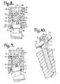
- FIG. 8is an enlarged partial front elevational view of the shank of FIG. 1 shown fully assembled with the retaining structure, receiver, rod and closure structure of FIG. 1 , with portions broken away to show the detail thereof.
- FIG. 9is a partial front elevational view with portions broken away similar to FIG. 8 , showing an articulation of the shank with respect to the receiver.
- FIG. 10is a partial perspective view, showing the shank, receiver, retaining structure, rod and closure structure of FIG. 1 fully assembled and implanted in a vertebra, shown in cross-section.
- FIG. 11is an exploded perspective view of a second embodiment of a polyaxial bone screw assembly according to the present invention having a shank, a receiver, and a retaining structure, and shown with a rod and a closure structure.
- FIG. 12is an enlarged front elevational view of the shank of FIG. 11 .
- FIG. 13is a cross-sectional view taken along the line 13 - 13 of FIG. 12 .
- FIG. 14is an enlarged top plan view of the shank of FIG. 12 .
- FIG. 15is an enlarged partial front elevational view of the shank of FIG. 11 shown fully assembled with the retaining structure, receiver, rod and closure structure of FIG. 11 , with portions broken away to show the detail thereof.
- FIG. 16is a partial front elevational view with portions broken away similar to FIG. 15 , showing an articulation of the shank with respect to the receiver.
- FIG. 17is a partial perspective view, showing the shank, receiver, retaining structure, rod and closure structure of FIG. 11 fully assembled and implanted in a vertebra, shown in cross-section.
- FIG. 18is an exploded perspective view of a third embodiment of a polyaxial bone screw assembly according to the present invention having a shank, a receiver, and a retaining structure, and shown with a rod and a closure structure.
- FIG. 19is an enlarged top plan view of the retaining structure of FIG. 18 .
- FIG. 20is a cross-sectional view taken along the line 20 - 20 of FIG. 19 .
- FIG. 21is an enlarged cross-sectional view of the receiver, taken along the line 21 - 21 of FIG. 18 .
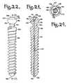
- FIG. 22is an enlarged front elevational view of the shank of FIG. 18 .
- FIG. 23is a cross-sectional view taken along the line 23 - 23 of FIG. 22 .
- FIG. 24is an enlarged top plan view of the shank of FIG. 22 .
- FIG. 25is an enlarged partial front elevational view of the shank of FIG. 18 shown fully assembled with the retaining structure, receiver, rod and closure structure of FIG. 18 , with portions broken away to show the detail thereof.
- FIG. 26is a partial front elevational view with portions broken away similar to FIG. 25 , showing an articulation of the shank with respect to the receiver.
- FIG. 27is a partial perspective view, showing the shank, receiver, retaining structure, rod and closure structure of FIG. 18 fully assembled and implanted in a vertebra, shown in cross-section.
- FIG. 28is an exploded perspective view of a fourth embodiment of a polyaxial bone screw assembly according to the present invention having a shank, a receiver, and a retaining structure, and shown with a rod and a closure structure.
- FIG. 29is an enlarged front elevational view of the shank of FIG. 28 .
- FIG. 30is a cross-sectional view taken along the line 30 - 30 of FIG. 29 .
- FIG. 31is an enlarged top plan view of the shank of FIG. 29 .
- FIG. 32is an enlarged partial front elevational view of the shank of FIG. 28 shown fully assembled with the retaining structure, receiver, rod and closure structure of FIG. 28 , with portions broken away to show the detail thereof.
- FIG. 33is a partial front elevational view with portions broken away similar to FIG. 32 , showing an articulation of the shank with respect to the receiver.
- the reference numeral 1generally represents a polyaxial bone screw assembly according to the present invention.
- the assembly 1includes a shank 4 that further includes a body 6 integral with an upwardly extending upper portion or capture structure 8 ; a receiver 10 ; and an independent open retaining structure 12 .
- the shank 4 , the receiver 10 and the retaining structure 12preferably are assembled prior to implantation of the shank body 6 into a vertebra 15 .
- FIGS. 1 and 8 - 10further show a closure structure 18 for compressing and biasing a longitudinal member such as a rod 21 against the shank upper portion 8 biasing the upper portion 8 into fixed frictional contact with the retaining structure 12 installed in the receiver 10 , so as to fix the rod 21 relative to the vertebra 15 .
- the receiver 10 , the retaining structure 12 and the shank 4cooperate in such a manner that the receiver 10 and the shank 4 can be secured at any of a plurality of angles, articulations or rotational alignments relative to one another and within a selected range of angles both from side to side and from front to rear, to enable flexible or articulated engagement of the receiver 10 with the shank 4 until both are locked or fixed relative to each other near an end of an implantation procedure.
- the shank 4is elongate, with the shank body 6 having a helically wound bone implantable thread 24 extending from near a neck 26 located adjacent to the capture structure 8 to a tip 28 of the body 6 and extending radially outwardly therefrom.
- the body 6utilizing the thread 24 for gripping and advancement is implanted into the vertebra 15 leading with the tip 28 and driven down into the vertebra 15 with an installation or driving tool (not shown), so as to be implanted in the vertebra 15 to near the neck 26 , as shown in FIG. 10 , and as is described more fully in the paragraphs below.
- the shank 4has an elongate axis of rotation generally identified by the reference letter A. It is noted that any reference to the words top, bottom, up and down, and the like, in this application refers to the alignment shown in the various drawings, as well as the normal connotations applied to such devices, and is not intended to restrict positioning of the assembly 1 in actual use.
- the neck 26extends axially outwardly and upwardly from the shank body 6 .
- the illustrated neck 26is of reduced radius as compared to the shank body 6 and an outer diameter of the thread 24 .
- the shank upper portion 8Further extending axially and outwardly from the neck 26 is the shank upper portion 8 that provides a connective or capture structure disposed at a distance from the thread 24 and thus at a distance from the vertebra 15 when the body 6 is implanted in the vertebra 15 .
- the shank upper portion 8is configured for connecting the shank 4 to the receiver 10 and capturing the shank 4 in the receiver 10 .
- the upper portion 8has an outer, convex and partially spherical or hemispherical surface 34 that extends outwardly and upwardly from the neck 26 and terminates at a substantially annular surface 38 .
- the spherical surface 34has an outer radius configured for sliding cooperation and ultimate frictional mating with a concave surface of the retaining structure 12 and a partially spherical inner surface of the receiver 10 , having a substantially similar radius, discussed more fully in the paragraphs below.
- the flat surface 38is substantially perpendicular to the axis A.
- the spherical surface 34 shown in the present embodimentis smooth, but it is foreseen that such surface may include a roughened or textured surface or surface finish, or may be scored, knurled, or the like, for enhancing frictional engagement with the retaining structure 12 and the receiver 10 .
- a counter sunk substantially planar base or seating surface 40also is disposed perpendicular to the axis A and extends radially from a centrally located tool engagement structure 41 .
- the sunken seating surface 40is disposed between the tool engagement structure and the surface 38 .
- the structure 41has a top 42 and six driving faces 43 that form a hexagonal extension head driving structure mateable with a socket driving tool (not shown).
- the base 40also includes a hexagonal outer perimeter 44 defined by outer driving faces that are parallel to the axis A and terminate at the surface 38 .
- the tool engagement structure 41is coaxial with the bone screw body 6 and extends along the axis A.
- a driving toolfits about and engages the tool engagement structure 41 at the faces 43 for both driving and rotating the shank body 6 into the vertebra 15 .
- a bottom of the driving toolmay abut against the base 40 and also the faces defining the outer hexagonal perimeter 44 , providing additional surfaces for engagement with the driving tool.
- the driving features of the bone screw shankmay take a variety of forms, including internal and external drives of different shapes and sized.
- a curved, concave surfacemay extend from the tool engagement structure to the outer spherical surface, allowing for the tool engagement structure to be designed with a somewhat longer axial length and thus providing a greater surface area for engagement with a driving tool, but without the planar seating surface 40 and additional planar driving faces because of the limitation of the small size of such a bone screw.
- the top end surface 42 of the shank 4is preferably curved or dome-shaped as shown in the drawings, for simple smooth contact engagement or positive mating engagement with the rod 21 , when the bone screw assembly 1 is assembled, as shown in FIGS. 8 and 9 and in any angular arrangement of the shank 4 relative to the receiver 10 .
- the surface 42is smooth. While not required in accordance with the practice of the invention, the surface 42 may be scored, knurled or the like to further increase frictional positive mating engagement between the surface 42 and the rod 21 .
- the shank 4 shown in the drawingsis cannulated, having a small central bore 45 extending an entire length of the shank 4 along the axis A, coaxial with the threaded body 6 .
- the bore 45has a first circular opening 46 at the shank tip 28 and a second circular opening 48 at the top surface 42 .
- the bore 45provides a passage through the shank 4 interior for a length of wire (not shown) inserted into the vertebra 15 prior to the insertion of the shank body 6 , the wire providing a guide for insertion of the shank body 6 into the vertebra 15 .
- the receiver 10has a generally U-shaped appearance with a discontinuous partially cylindrical inner profile and a faceted outer profile.
- the receiver 10includes a base 50 integral with a pair of upstanding arms 52 and 54 forming a U-shaped cradle and defining a U-shaped channel 56 between the arms 52 and 54 with an upper opening 57 and a lower seat 58 having substantially the same radius as the rod 21 for operably snugly receiving the rod 21 .
- Each of the arms 52 and 54has an interior surface 60 that in part defines the inner cylindrical profile and includes a partial helically wound guide and advancement structure 62 having an axis of rotation B.
- the guide and advancement structure 62is a partial helically wound interlocking flangeform configured to mate under rotation with a similar structure on the closure structure 18 , as described more fully below.
- the guide and advancement structure 62could alternatively be another type of splay preventing structure such as a buttress thread, a square thread, a reverse angle thread or other thread like or non-thread like helically wound discontinuous advancement structure for operably guiding under rotation and advancing the closure structure 18 downward between the arms 52 and 54 , as well as eventual torquing when the closure structure 18 abuts against the rod 21 .
- Tool engaging apertures or grip bores 64are formed within the arms 52 and 54 and may be used for holding the receiver 10 during assembly with the shank 4 and the retaining structure 12 and also during the implantation of the shank body 6 into a vertebra 15 .
- a holding tool(not shown) and the apertures 64 can be configured for a snap on/spring off, snap on/twist off, twist on/twist off, twist on/pry off or other flexible engagement wherein the holding tool has flexible legs which splay outwardly to position the tool for engagement in the apertures 64 .
- the apertures 64 the cooperating holding toolmay be configured to be of a variety of sizes and locations along any of the surfaces of the arms 52 and 54 .
- the apertures 64communicate with upwardly projecting hidden recesses 66 to further aid in securely holding the receiver 10 to a holding tool.
- a chamber or cavity 78substantially defined by an inner, substantially spherical or partially cylindrical surface 80 of the base 50 and an inner substantially spherical concave surface 82 that communicates with the U-shaped channel 56 .
- the spherical surface 82is disposed between the channel 56 and the inner surface 80 .
- a circumferential ridge 83is formed at the intersection of the inner surface 60 and the inner substantially spherical surface 82 .
- the substantially spherical surface 82is sized and shaped for slidable mating and eventual frictional engagement with the shank upper portion 8 , having a radius that is approximately the same as a radius of the convex surface 34 of the shank upper portion 8 as described more fully below.
- the concave spherical surface 82opens or widens at the lower surface 80 , the surface 80 being sized to receive a shank upper portion 8 bottom loaded at a lower opening 84 of the receiver 10 where the surface 80 opens to an exterior 85 of the base 50 . It is foreseen that if desired, some of the lower surface 80 may be cylindrical in nature (similar to the surface 280 of the assembly 201 ), rather than partially spherical as shown in FIG. 4 .
- the spherical surface 82provides a stop, upper shoulder or barrier near and at the ridge 83 prohibiting the shank upper portion 8 from being removable through the channel 56 .
- the lower inner surface that opens to the exterior 85 of the base 50is coaxially aligned with respect to the rotational axis B of the receiver 10 and is sized and shaped to receive the shank upper portion 8 therethrough and also receive the retaining structure 12 when the structure 12 is in a compressed configuration as will be described in greater detail below.
- a circumferential recess or groove 86Formed in a portion of the surface 80 near the spherical inner surface 82 is a circumferential recess or groove 86 that is sized and shaped to receive the retaining structure 12 when the structure 12 is in an uncompressed position as will also be discussed further below, so as to form a restriction at the location of the groove 86 to prevent the uncompressed retaining structure 12 from passing from the cavity 78 and out the lower opening 84 of the receiver 10 when the retaining structure 12 is loaded and seated in the groove 86 , thereby also retaining the shank upper portion 8 within the cavity 78 .
- the receiverBetween the groove 86 and the opening 84 communicating with the base exterior 85 , the receiver includes a chamfer or conical surface 88 . As illustrated in FIG. 9 , the surface 88 provides additional clearance for an angled or articulated bone screw shank 4 with respect to the receiver 10 .
- the retaining structure or collar 12 that is used to retain the capture structure 8 of the shank 4 within the receiver 10is best illustrated by FIGS. 1-3 .
- the structure 12has a central axis C that is operationally the same as the axis B associated with the receiver 10 when the capture structure 8 and the retaining structure 12 are installed within the receiver 10 .
- the retaining structure 12has a central channel or hollow 91 that passes entirely through the structure 12 from a top surface 92 to a bottom surface 94 thereof.
- Surfaces that define the channel 91include a discontinuous inner spherical surface 95 adjacent the top surface 92 ; an edge 97 adjacent the surface 95 and coaxial with the axis C; and a discontinuous conical surface, bevel or chamfer 98 sloping away from the axis C, adjacent the edge 97 and terminating at the bottom surface 94 .
- the spherical surface 95has a radius sized and shaped to cooperate with a radius of the substantially spherical surface 34 of the shank upper portion 8 such that the surface 95 slidingly and pivotally mates with the spherical surface 34 as described more fully below.
- the surface 95may include a roughening or surface finish for providing additional frictional contact between the surface 95 and the surface 34 , once a desired angle of articulation of the shank 4 with respect to the receiver 10 is reached.
- the resilient retaining structure 12includes first and second end surfaces, 100 and 101 disposed in spaced relation to one another and an outer substantially cylindrical surface 104 . Both end surfaces 100 and 101 are disposed substantially perpendicular to the top surface 92 and the bottom surface 94 .
- a width X between the surfaces 100 and 101is determined by a desired amount of compressibility of the open retaining structure 12 when loaded into the receiver 10 .
- the space X shown in FIG. 2provides adequate space between the surfaces 100 and 101 for the retaining structure 12 to be pinched, with the surfaces 100 and 101 compressed toward one another to an almost touching or touching configuration, to an extent that the compressed retaining structure 12 is up or bottom loadable through the opening 84 .
- the retaining structure 12After passing through the opening 84 and along a portion of the lower inner surface, the retaining structure 12 expands or springs back to an original uncompressed, rounded or collar-like configuration of FIG. 2 once in the groove 86 .
- the embodiment shown in FIG. 2illustrates the surfaces 100 and 101 as substantially parallel and vertical, however, it is foreseen that it may be desirable to orient the surfaces obliquely or at a slight angle depending upon the amount of compression desired during loading of the retaining and articulating structure 12 into the receiver 10 .
- FIGS. 8 and 9illustrate the structure 12 installed in the groove 86 of the receiver 10 and in engagement with the shank upper portion 8 .
- FIG. 8illustrates the shank 4 , receiver 10 and retaining structure 12 in co-axial alignment. In other words, axes A, B and C are aligned.
- FIG. 9illustrates an articulating or swiveling relationship between the upper portion 8 and the installed retaining structure 12 wherein the bone screw upper portion 8 is slidable with respect to the retaining structure 12 at the surface 95 , resulting in an orientation wherein the axis A of the shank 4 is not axially aligned with, but rather disposed at an angle with respect to the axes B and C of the receiver 10 and the retaining structure 12 respectively.
- the elongate rod or longitudinal member 21 that is utilized with the assembly 1can be any of a variety of implants utilized in reconstructive spinal surgery, but is normally a cylindrical elongate structure having a smooth cylindrical surface 116 of uniform diameter.
- the rod 21is preferably sized and shaped to snugly seat near the bottom of the U-shaped channel 56 of the receiver 10 and, during normal operation, is positioned slightly above the bottom of the channel 56 at the lower seat 58 .
- the rod 21normally directly or abutingly engages the shank top surface 42 , as shown in FIGS. 8 and 9 and is biased against the domed shank top surface 42 , consequently biasing the shank 4 downwardly in a direction toward the base 50 of the receiver 10 when the assembly 1 is fully assembled.
- the shank top surface 42must extend at least slightly into the space of the channel 56 when engaging the retaining structure 12 .
- the shank 4is thereby locked or held in position relative to the receiver 10 by the rod 21 firmly pushing downward on the shank top surface 42 .
- the closure structure or closure top 18can be any of a variety of different types of closure structures for use in conjunction with the present invention with suitable mating structure on the upstanding arms 52 and 54 .
- the closure top 18is rotatably received between the spaced arms 52 and 54 . It is foreseen that a mating and advancement structure could be located on the external surfaces of the arms 52 and 54 for mating with a closure top.
- the illustrated closure top 18has a generally cylindrical shaped base 128 with an upwardly extending break-off head 130 .
- the base 128includes a helically wound guide and advancement structure 131 that is sized, shaped and positioned so as to engage the guide and advancement structure 62 on the arms 52 and 54 to provide for rotating advancement of the closure structure 18 into the receiver 10 when rotated clockwise and, in particular, to cover the top or upwardly open portion 57 of the U-shaped channel 56 to capture the rod 21 , preferably without splaying of the arms 52 and 54 .
- the base 128has a lower or bottom surface 132 with a centrally located pointed projection 133 for engaging and penetrating the rod 21 at the rod surface 116 .
- a circumferential rimmay also extend from the bottom surface 132 , the rim providing additional engagement points with the rod surface 116 .
- the closure structure 18operably biases against the rod 21 by advancement and applies pressure to the rod 21 under torquing, so that the rod 21 is urged downwardly against the shank top end surface 42 that extends into the channel 56 .
- Downward biasing of the shank top surface 42operably produces a frictional engagement between the rod 21 and the surface 42 and also urges the shank upper portion 8 toward the retaining structure 12 that has been loaded into the receiver 10 and expanded into the groove 86 , so as to frictionally engage the spherical surface 34 of the shank upper portion 8 with the spherical surface 95 of the retaining structure 12 fixing the shank 4 in a selected, rigid position relative to the receiver 10 .
- a closure structure for use with the assembly 1may not include a break-off head, but rather simply have a cylindrical body with a guide and advancement structure thereon and a top surface with an internal tool engagement structure formed therein, such as a hex aperture or a variety of internal tool-engaging forms of various shapes, such as a multi-lobular aperture sold under the trademark TORX, or the like.
- the illustrated closure structure 18also includes an internal drive removal tool engagement structure 140 in the form of an axially aligned aperture having a hex shape, disposed in the base 128 .
- the internal drive or aperture 140is accessible after the break-off head 130 breaks away from the base 128 .
- the drive 140is designed to receive a hex tool, of an Allen wrench type, for rotating the closure structure base 128 subsequent to installation so as to provide for removal thereof, if necessary.
- Such a tool engagement structuremay take a variety of tool-engaging forms and may include one or more apertures of various shapes, such as a pair of spaced apart apertures, or a left hand threaded bore, or an easyout engageable step down bore, or a multi-lobular aperture, such as those sold under the trademark TORX, or the like.
- the retaining structure 12is preferably first inserted about the bone screw shaft 6 . This may be accomplished by either placing the structure 12 over the tip 28 and moving the structure 12 toward the upper portion 8 with the shaft 6 extending through the central channel 91 or inserting the structure 12 on the bone screw 4 at the neck 26 of the shank body 6 , with the end surfaces 100 and 101 being pulled away from one another and pressed against and about the neck 26 until the surfaces 100 and 101 expand around the neck 26 and then spring back into a first position with the inner surface 95 facing the surface 34 of the shank upper portion 8 .
- the shank upper portion 8 and the connected structure 12are then simultaneously up or bottom-loaded into the receiver through the opening 84 with the upper portion 8 being placed into the cavity 78 .
- the structure 12is manually compressed by pinching the surfaces 100 and 101 toward one another as the neck 26 is placed into the opening 84 until the structure 12 is aligned with the groove 86 .
- the compressive forceis then removed and the structure 12 resiliently springs back and returns to the original ring-like or collar-like orientation. Then, as illustrated in FIGS.
- the top surface 92 , bottom surface 94 and outer cylindrical surface 104 of the structure 12frictionally engage the groove 86 , fixing the retaining structure 12 in the receiver 10 and capturing the shank upper portion 8 within the receiver and in sliding, pivotal relationship with the spherical surface 95 of the retaining structure 12 , and in certain angular orientations or articulations, with the spherical surface 82 of the receiver 10 .
- the bone screw shank upper portion 8is first placed in the receiver 10 by inserting the upper portion 8 through the opening 84 and into the cavity 78 .
- the retaining structure 12may then be placed over the shank body 6 at the tip 28 and moved toward the shank upper portion 8 .
- the structure 12is manually compressed by pinching the surfaces 100 and 101 toward one another as the structure 12 is placed in the opening 84 until the structure 12 is aligned with the groove 86 .
- the compressive forceis then removed and the structure 12 resiliently springs back and returns to the original ring-like or collar-like orientation, fixing the structure 12 in the receiver 10 and capturing the shank upper portion 8 within the receiver cavity 78 .
- the capture structure 8may then be manipulated into a position substantially coaxial with the receiver 10 in readiness for bone implantation.
- the assembly 1is typically screwed into a bone, such as the vertebra 15 , by rotation of the shank 4 using a driving tool (not shown) that operably drives and rotates the shank 4 by engagement thereof with the faces 43 of the hexagonally shaped tool engagement structure 41 of the shank 4 .
- a driving tool(not shown) that operably drives and rotates the shank 4 by engagement thereof with the faces 43 of the hexagonally shaped tool engagement structure 41 of the shank 4 .
- a bottom or end portion thereofabuts the countersunk planar seating surface 40 and outer surfaces of the driving tool engage the walls that define the outer perimeter 44 , providing an additional driving interface.
- the receiver 10 and the retaining structure 12are assembled on the shank 4 before inserting the shank body 6 into the vertebra 15 as previously described hereon.
- the shank body 6can be first partially implanted with the capture structure 8 extending proud to allow placement of the retaining structure 12 about the neck 26 , followed by assembly with the receiver 10 . Then the shank body 6 can be further driven into the vertebra 15 .
- the vertebra 15may be pre-drilled to minimize stressing the bone and have a guide wire (not shown) inserted to provide a guide for the placement and angle of the shank 4 with respect to the vertebra 15 .
- a further tap holemay be made using a tap with the guide wire as a guide.
- the assembly 1 or the solitary shank 4is threaded onto the guide wire utilizing the cannulation bore 45 by first threading the wire into the bottom opening 46 and then out of the top opening 48 .
- the shank 4is then driven into the vertebra 15 , using the wire as a placement guide.
- the rod 21is eventually positioned within the receiver U-shaped channel 56 , and the closure structure or top 18 is then inserted into and advanced between the arms 52 and 54 so as to bias or push against the rod 21 .
- the break-off head 130 of the closure structure 18is twisted to a preselected torque, for example 90 to 120 inch pounds, to urge the rod 21 downwardly.
- the shank top end surface 42because it is rounded to approximately equally extend upward into the channel 56 approximately the same amount no matter what degree of rotation exists between the shank 4 and receiver 10 and because the surface 42 is sized to extend upwardly into the U-shaped channel 56 , the surface 42 is engaged by the rod 21 and pushed downwardly toward the base 50 of the receiver 10 when the closure structure 18 biases downwardly toward and onto the rod 21 .
- the downward pressure on the shank 4urges the shank top portion 8 downward toward the retaining structure 12 and possibly against the receiver seating surface 82 .
- the rod 21presses against the shank upper portion 8 that becomes frictionally, rigidly attached to the receiver 10 at the retaining structure 12 .
- FIG. 8illustrates the polyaxial bone screw assembly 1 and including the rod 21 and the closure structure 18 positioned at a level or extent of articulation in which the axis A of the bone screw shank and the axis B of the receiver are coaxial.
- FIGS. 9 and 10illustrate the assembly 1 with the axis A of the bone shank 4 at an angle with respect to the axis B of the receiver 10 , and with the shank 4 being fixed in such angular locked configuration and implanted in the vertebra 15 .
- disassemblyis accomplished by using a driving tool (not shown) mating with driving surfaces of the aperture 140 on the closure structure 18 to rotate the base 138 and reverse the advancement thereof in the receiver 10 . Then, disassembly of the assembly 1 is accomplished in reverse order to the procedure described previously herein for assembly.
- the reference numeral 201generally represents a second or alternative embodiment of a bone screw assembly according to the present invention.
- the assembly 201includes a shank 204 that further includes a body 206 integral with an upwardly extending upper portion or capture structure 208 ; a receiver 210 ; and an independent open retaining structure 212 .
- the shank 204 , the receiver 210 and the retaining structure 212preferably are assembled prior to implantation of the shank body 206 into a vertebra 215 .
- FIGS. 11 and 15 - 17further show a closure structure 218 for compressing and biasing a longitudinal member such as a rod 221 against the shank upper portion 208 biasing the upper portion 208 into fixed frictional contact with the retaining structure 212 installed in the receiver 210 , so as to fix the rod 221 relative to the vertebra 215 .
- a closure structure 218for compressing and biasing a longitudinal member such as a rod 221 against the shank upper portion 208 biasing the upper portion 208 into fixed frictional contact with the retaining structure 212 installed in the receiver 210 , so as to fix the rod 221 relative to the vertebra 215 .
- the receiver 210 , the retaining structure 212 and the shank 204cooperate in such a manner that the receiver 210 and the shank 204 can be secured at any of a plurality of angles, articulations or rotational alignments relative to one another and within a selected range of angles both from side to side and from front to rear, to enable flexible or articulated engagement of the receiver 210 with the shank 204 until both are locked or fixed relative to each other near an end of an implantation procedure.
- the shank 204is elongate, with the shank body 206 having a helically wound bone implantable thread 224 extending from near a neck 226 located adjacent to the shank upper portion 208 to a tip 228 of the body 206 and extending radially outwardly therefrom.
- the body 206utilizing the thread 224 for gripping and advancement is implanted into the vertebra 215 leading with the tip 228 and driven down into the vertebra 215 with an installation or driving tool (not shown), so as to be implanted in the vertebra 215 to near the neck 226 , as shown in FIG. 17 , and as is described more fully in the paragraphs below.
- the shank 204has an elongate axis of rotation generally identified by the reference letter D.
- the neck 226extends axially outwardly and upwardly from the shank body 206 .
- the illustrated neck 226is of reduced radius as compared to the shank body 206 and an outer diameter of the thread 224 .
- the shank upper portion 208that provides a connective or capture structure disposed at a distance from the thread 224 and thus at a distance from the vertebra 215 when the body 206 is implanted in the vertebra 215 .
- the shank upper portion 208is configured for connecting the shank 204 to the receiver 210 and capturing the shank 204 in the receiver 210 .
- the upper portion 208has an outer, convex and substantially spherical surface 234 that extends outwardly and upwardly from the neck 226 and terminates at a substantially planar top surface 238 .
- the spherical surface 234has an outer radius configured for sliding cooperation and ultimate frictional mating with a concave surface of the retaining structure 212 and a substantially spherical inner surface of the receiver 210 , having a substantially similar radius, discussed more fully in the paragraphs below.
- the flat surface 238is substantially perpendicular to the axis D.
- the spherical surface 234 shown in the present embodimentis smooth, but it is foreseen that the surface 234 may include a roughened or textured surface or surface finish, or may be scored, knurled, or the like, for enhancing frictional engagement with the retaining structure 212 and the receiver 210 .
- a counter sunk substantially planar base or seating surface 240partially defines an internal drive feature or imprint 241 .
- the illustrated internal drive feature 241is an aperture formed in the top 238 and has a hex shape designed to receive a hex tool of an Allen wrench type, into the aperture for rotating and driving the bone screw shank 204 .
- such an internal tool engagement structuremay take a variety of tool-engaging forms and may include one or more apertures of various shapes, such as a pair of spaced apart apertures or a multi-lobular aperture, such as those sold under the trademark TORX, or the like.
- the seat or base 240 of the drive feature 241is disposed perpendicular to the axis D with the drive feature 241 otherwise being coaxial with the axis D.
- Six driving faces or walls 242each disposed parallel to the axis D also define the feature 241 .
- the planar top surface 238extends from a hexagonal outer perimeter 244 defined by the driving faces 242 and terminates at a circular edge 243 .
- the circular edge 243also defines a top or terminating upper edge of the spherical outer surface 234 .
- a driving tool(not shown) is received in the internal drive feature 241 , being seated at the base 240 and engaging the faces 242 for both driving and rotating the shank body 206 into the vertebra 215 .
- the shank 204 shown in the drawingsis cannulated, having a small central bore 245 extending an entire length of the shank 204 along the axis D, coaxial with the threaded body 206 .
- the bore 245has a first circular opening 246 at the shank tip 228 and a second circular opening 248 at the driving feature seating surface 240 .
- the bore 245provides a passage through the shank 204 interior for a length of wire (not shown) inserted into the vertebra 215 prior to the insertion of the shank body 206 , the wire providing a guide for insertion of the shank body 206 into the vertebra 215 .
- the receiver 210has an axis of rotation E and is substantially similar to the receiver 10 previously described herein.
- the description of the receiver 10is incorporated by reference with respect to the receiver 210 .
- the receiver 210includes a receiver base 250 , arms 252 and 254 , a U-shaped channel 256 with an upper opening 257 , a lower seat 258 , an interior surface 260 , guide and advancement structure 262 , grip bores 264 , recesses 266 , a chamber or cavity 278 , a lower inner surface 280 , an inner spherical surface 282 , a ridge 283 , a lower opening 284 , a base exterior 285 and a groove 286 the same or substantially similar to the respective base 50 , arms 52 and 54 , U-shaped channel 56 with upper opening 57 , lower seat 58 , interior surface 60 , guide and advancement structure 62 , grip bores 64 , recesses 66
- the retaining structure or collar 212 that is used to retain the capture structure 208 of the shank 204 within the receiver 210is best illustrated in FIGS. 11 and 15 - 16 .
- the structure 212has a central axis F that is operationally the same as the axis E associated with the receiver 210 when the capture structure 208 and the retaining structure 212 are installed within the receiver 210 .
- the retaining structure 212is the same or substantially similar to the retaining structure 12 previously described herein and thus the description of the structure 12 is incorporated by reference herein with respect to the structure 212 .
- the structure 212includes a central channel 291 , a top 292 , a bottom 294 , a partially spherical inner surface 295 , a conical surface or chamfer 298 , end surfaces 300 and 301 and an outer cylindrical surface 304 , the same or substantially similar to respective central channel 91 , top 92 , bottom 94 , spherical inner surface 95 , conical surface 98 , end surfaces 100 and 101 and outer cylindrical surface 104 of the retaining structure 12 .
- a width or space between the surfaces 300 and 301is determined by a desired amount of compressibility of the open retaining structure 212 when loaded into the receiver 210 .
- the space shown in FIG. 11 between the surfaces 300 and 301provides an adequate distance between the surfaces 300 and 301 for the retaining structure 212 to be pinched, with the surfaces 300 and 301 compressed toward one another to an almost touching or touching configuration, to an extent that the compressed retaining structure 212 is up or bottom loadable through the opening 284 . As illustrated in FIG.
- the surfaces 300 and 301are substantially parallel and vertical, however, it is foreseen that it may be desirable to orient the surfaces obliquely or at a slight angle depending upon the amount of compression desired during loading of the retaining and articulating structure 212 into the receiver 210 .
- the retaining structure 212After passing through the opening 284 and along a portion of the cylindrical inner surface 280 , the retaining structure 212 expands or springs back to an original uncompressed, rounded or collar-like configuration once in the groove 286 .
- 15 and 16illustrate the structure 212 in a fully installed position in the receiver 210 and having an articulating or swiveling relationship with the upper portion 208 of the bone screw shank 204 wherein the bone screw upper portion 208 is slidable with respect to the retaining structure 212 at the surface 295 .
- the elongate rod or longitudinal member 221 that is utilized with the assembly 201can be any of a variety of implants utilized in reconstructive spinal surgery, but is normally a cylindrical elongate structure having a smooth cylindrical surface 316 of uniform diameter.
- the rod 221is preferably sized and shaped to snugly seat near the bottom of the U-shaped channel 256 of the receiver 210 and, during normal operation, is positioned slightly above the bottom of the channel 256 at the lower seat 258 .
- the rod 221directly or abutingly engages the upper portion 208 of the shank 204 either at the top 238 , the circular edge 243 or the spherical surface 234 , as shown in FIGS.
- the shank upper portion 208must extend at least slightly into the space of the channel 256 when engaging the retaining structure 212 .
- the shank 204is thereby locked or held in position relative to the receiver 210 by the rod 221 firmly pushing downward on the shank upper portion 208 .
- the closure structure or closure top 218can be any of a variety of different types of closure structures for use in conjunction with the present invention with suitable mating structure on the upstanding arms 252 and 254 .
- the closure top 218is rotatably received between the spaced arms 252 and 254 . It is foreseen that a mating and advancement structure could be located on the external surfaces of the arms 252 and 254 for mating with a closure top.
- the illustrated closure structure 218is substantially cylindrical, having a top 328 and a bottom 329 .
- the closure structure 218further includes a helically wound guide and advancement structure 331 that is sized, shaped and positioned so as to engage the guide and advancement structure 262 on the arms 252 and 254 to provide for rotating advancement of the closure structure 218 into the receiver 210 when rotated clockwise and, in particular, to cover the top or upwardly open portion 257 of the U-shaped channel 256 to capture the rod 221 , preferably without splaying of the arms 252 and 254 .
- the closure structure bottom 329includes a centrally located pointed projection 333 for engaging and penetrating the rod 221 at the rod surface 316 .
- a circumferential rimmay also extend from the bottom surface 329 , the rim providing additional engagement points with the rod surface 316 .
- the closure structure 218operably biases against the rod 221 by advancement and applies pressure to the rod 221 , so that the rod 221 is urged downwardly against the shank upper portion 208 that extends into the channel 256 .
- Downward biasing of the shank upper portion 208operably produces a frictional engagement between the rod 221 and the upper portion 208 and also urges the shank upper portion 208 toward the retaining structure 212 that has been loaded into the receiver 210 and expanded into the groove 286 , so as to frictionally engage the spherical surface 234 of the shank upper portion 208 with the spherical surface 295 of the retaining structure 212 fixing the shank 204 in a selected, rigid position relative to the receiver 210 .
- the illustrated shank upper portion 208includes the flat surface 238 , circular edge 243 and spherical surface 234 and the rod 221 may engage any of such surfaces, the rod 221 may be seated at a distance from the receiver lower seat 258 and the closure structure 218 may not be disposed flush to a top of the receiver 210 when fully engaged with the rod 221 biasing the rod 221 into locking engagement with the shank 204 .
- Such placement of the closure structure 218 and the rod 221does not hinder the closure structure 218 from seating in the receiver 210 and fixing the rod 221 in a locked position within the receiver 210 .
- an internal drive feature 336Formed in the closure structure 218 top surface 328 is an internal drive feature 336 sized and shaped to receive a mating driving tool (not shown) to rotate and torque the closure structure 218 against the rod 221 .
- the illustrated drive feature 336is multi-lobular, but it is foreseen that the internal drive feature may be a hex aperture or a variety of internal tool-engaging forms of various shapes.
- the drive feature 336may also be used to remove the closure structure 218 from the receiver 210 subsequent to installation, if desired or necessary.
- the retaining structure 212is preferably first inserted about the bone screw shaft 206 . This may be accomplished by either placing the structure 212 over the tip 228 and moving the structure 212 toward the upper portion 208 with the shaft 206 extending through the central channel 291 or inserting the structure 212 on the bone screw 204 at the neck 226 of the shank body 206 , with the end surfaces 300 and 301 being pulled away from one another and pressed against and about the neck 226 until the surfaces 300 and 301 expand around the neck 226 and then spring back into a first position with the inner surface 295 facing the surface 234 of the shank upper portion 208 .
- the shank upper portion 208 and the connected structure 212are then simultaneously up or bottom-loaded into the receiver through the opening 284 with the upper portion 208 being placed into the cavity 278 .
- the structure 212is manually compressed by pinching the surfaces 300 and 301 toward one another as the neck 226 is placed into the opening 284 until the structure 212 is aligned with the groove 286 .
- the compressive forceis then removed and the structure 212 resiliently springs back and returns to the original ring-like or collar-like orientation. Then, as illustrated in FIG.
- the top surface 292 , bottom surface 294 and outer cylindrical surface 304 of the structure 212frictionally engage the groove 286 , fixing the retaining structure 212 in the receiver 210 and capturing the shank upper portion 208 within the receiver and in sliding, pivotal relationship with the spherical surface 295 of the retaining structure 212 and with the spherical surface 282 of the receiver 210 .
- the bone screw shank upper portion 208is first placed in the receiver 210 by inserting the upper portion 208 through the opening 284 and into the cavity 278 .
- the retaining structure 212may then be placed over the shank body 206 at the tip 228 and moved toward the shank upper portion 208 .
- the structure 212is manually compressed by pinching the surfaces 300 and 301 toward one another as the structure 212 is placed in the opening 284 until the structure 212 is aligned with the groove 286 .
- the compressive forceis then removed and the structure 212 resiliently springs back and returns to the original ring-like or collar-like orientation, fixing the structure 212 in the receiver 210 and capturing the shank upper portion 208 within the receiver cavity 278 .
- the capture structure 208may then be manipulated into a position substantially coaxial with the receiver 210 in readiness for bone implantation.
- the assembly 201is typically screwed into a bone, such as the vertebra 215 , by rotation of the shank 204 using a driving tool (not shown) that operably drives and rotates the shank 204 by engagement thereof with the base 240 and the faces 242 of the internal drive feature 241 .
- the receiver 210 and the retaining structure 212are assembled on the shank 204 before inserting the shank body 206 into the vertebra 215 as previously described hereon.
- the shank body 206can be first partially implanted with the capture structure 208 extending proud to allow placement of the retaining structure 212 about the neck 226 , followed by assembly with the receiver 210 . Then the shank body 206 can be further driven into the vertebra 215 .
- the vertebra 215may be pre-drilled to minimize stressing the bone and have a guide wire (not shown) inserted to provide a guide for the placement and angle of the shank 204 with respect to the vertebra 215 .
- a further tap holemay be made using a tap with the guide wire as a guide.
- the assembly 201 or the solitary shank 204is threaded onto the guide wire utilizing the cannulation bore 245 by first threading the wire into the bottom opening 246 , then out of the top opening 248 and then through and out of the driving feature 241 .
- the shank 204is then driven into the vertebra 215 , using the wire as a placement guide.
- the rod 221is eventually positioned within the receiver U-shaped channel 256 , and the closure structure or top 218 is then inserted into and advanced between the arms 252 and 254 so as to bias or push against the rod 221 and urge the rod 221 downwardly.
- the rod 221comes into contacted with the planar top surface 238 (shown in FIG. 15 ), the circular edge 243 (shown in FIG.
- the closure structure 218biases downwardly toward and onto the rod 221 .
- the downward pressure on the shank 204urges the shank top portion 208 downward toward the retaining structure 212 and typically against the receiver seating surface 282 .
- the rod 221presses against the shank upper portion 208 that becomes frictionally, rigidly attached to the receiver 210 at the retaining structure 212 .
- FIGS. 15-17illustrates the polyaxial bone screw assembly 201 and including the rod 221 and the closure structure 218 positioned at various articulations or locked angular orientations in which the axis D of the bone screw shank and the axis E of the receiver are not coaxial.
- FIG. 17also shows the shank 204 implanted in the vertebra 15 .
- full locking installationis obtainable when the rod 221 engages the rim 243 or the spherical surface 234 , even though such engagement places the rod 221 higher in the channel 256 and therefore the closure structure 218 does not seat in a manner that is flush with the top surface of the receiver 210 .
- disassemblyis accomplished by using a driving tool (not shown) mating with the internal drive 336 on the closure structure 218 to rotate the structure 218 and reverse the advancement thereof in the receiver 210 . Then, disassembly of the assembly 201 is accomplished in reverse order to the procedure described previously herein for assembly.
- the reference numeral 401generally represents a third or alternative embodiment of a bone screw assembly according to the present invention.
- the assembly 401includes a shank 404 that further includes a body 406 integral with an upwardly extending upper portion or capture structure 408 ; a receiver 410 ; and an independent open retaining structure 412 .
- the shank 404 , the receiver 410 and the retaining structure 412preferably are assembled prior to implantation of the shank body 406 into a vertebra 415 .
- FIGS. 18 and 25 - 27further show a closure structure 418 for compressing and biasing a longitudinal member such as a rod 421 against the shank upper portion 408 biasing the upper portion 408 into fixed frictional contact with the retaining structure 412 installed in the receiver 410 , so as to fix the rod 421 relative to the vertebra 415 .
- a closure structure 418for compressing and biasing a longitudinal member such as a rod 421 against the shank upper portion 408 biasing the upper portion 408 into fixed frictional contact with the retaining structure 412 installed in the receiver 410 , so as to fix the rod 421 relative to the vertebra 415 .
- the receiver 410 , the retaining structure 412 and the shank 404cooperate in such a manner that the receiver 410 and the shank 404 can be secured at any of a plurality of angles, articulations or rotational alignments relative to one another and within a selected range of angles both from side to side and from front to rear, to enable flexible or articulated engagement of the receiver 410 with the shank 404 until both are locked or fixed relative to each other near an end of an implantation procedure.
- the shank 404is elongate, with the shank body 406 having a helically wound bone implantable thread 424 extending from near a neck 426 located adjacent to the shank upper portion 408 to a tip 428 of the body 406 and extending radially outwardly therefrom.
- the body 406utilizing the thread 424 for gripping and advancement is implanted into the vertebra 415 leading with the tip 428 and driven down into the vertebra 415 with an installation or driving tool (not shown), so as to be implanted in the vertebra 415 to near the neck 426 , as shown in FIG. 27 , and similar to what has been described previously with respect to the similar bone screw assemblies 1 and 201 .
- the shank 404has an elongate axis of rotation generally identified by the reference letter G.
- the neck 426extends axially outwardly and upwardly from the shank body 406 .
- the illustrated neck 426is of reduced radius as compared to the shank body 406 and an outer diameter of the thread 424 .
- the shank upper portion 408Further extending axially and outwardly from the neck 426 is the shank upper portion 408 that provides a connective or capture structure disposed at a distance from the thread 424 and thus at a distance from the vertebra 415 when the body 406 is implanted in the vertebra 415 .
- the shank upper portion 408is configured for connecting the shank 404 to the receiver 410 and capturing the shank 404 in the receiver 410 .
- the upper portion 408has an outer, lower, convex and partially spherical surface 434 that extends outwardly and upwardly from the neck 426 and terminates at a substantially planar annular surface 436 .
- a second, upper convex partially spherical surface 437extends from the planar surface 436 to a planar and annular top surface 438 .
- the lower spherical surface 434is substantially hemispherical and has an outer radius configured for sliding cooperation and ultimate frictional mating with a concave surface of the retaining structure 412 and a substantially spherical inner surface of the receiver 410 , having a substantially similar radius, discussed more fully below.
- the planar or flat surfaces 436 and 438are both substantially perpendicular to the shank axis G.
- the partially spherical surface 434 shown in the present embodimentis smooth, but it is foreseen that the surface 434 may include a roughened or textured surface or surface finish, or may be scored, knurled, or the like, for enhancing frictional engagement with the retaining structure 412 and the receiver 410 .
- the upper, partially spherical surface 437has a radius that is smaller than the radius of the lower spherical surface 434 .
- the pair of spherical surfaces 434 and 437 of the shank upper portion 408cooperate with the smaller upper spherical surface 437 providing a more compact structure with greater clearance between the upper spherical surface 437 and the inner walls of the receiver 410 than available to the single spherical surface 234 , allowing for ease in articulation and a slightly greater degree of angulation of the shank 408 with respect to the receiver 410 than provided by the assembly 201 .
- a counter sunk substantially planar base or seating surface 440partially defines an internal drive feature or imprint 441 .
- the illustrated internal drive feature 441is an aperture formed in the top 438 and has a hex shape designed to receive a hex tool of an Allen wrench type, into the aperture for rotating and driving the bone screw shank 404 .
- an internal tool engagement structuremay take a variety of tool-engaging forms and may include one or more apertures of various shapes, such as a pair of spaced apart apertures or a multi-lobular aperture, such as those sold under the trademark TORX, or the like.
- the seat or base 440 of the drive feature 441is disposed perpendicular to the axis G with the drive feature 441 otherwise being coaxial with the axis G.
- Six driving faces or walls 442each disposed parallel to the axis G also define the feature 441 .
- the planar top surface 438extends from a hexagonal outer perimeter 444 defined by the driving faces 442 and terminates at a circular edge 443 .
- the circular edge 443also defines a top or terminating upper edge of the upper spherical outer surface 437 .
- a driving tool(not shown) is received in the internal drive feature 441 , being seated at the base 440 and engaging the faces 442 for both driving and rotating the shank body 406 into the vertebra 415 .
- the shank 404 shown in the drawingsis cannulated, having a small central bore 445 extending an entire length of the shank 404 along the axis G, coaxial with the threaded body 406 .
- the bore 445has a first circular opening 446 at the shank tip 428 and a second circular opening 448 at the driving feature seating surface 440 .
- the bore 445provides a passage through the shank 404 interior for a length of wire (not shown) inserted into the vertebra 415 prior to the insertion of the shank body 406 , the wire providing a guide for insertion of the shank body 406 into the vertebra 415 .
- the receiver 410is substantially similar to the receivers 10 and 210 previously described herein and thus those descriptions are incorporated by reference herein with respect to the receiver 410 .
- the receiver 410has an axis of rotation H and further includes a receiver base 450 , arms 452 and 454 , a U-shaped channel 456 with an upper opening 457 , a lower seat 458 , an interior surface 460 , guide and advancement structure 462 , grip bores 464 , a chamber or cavity 478 , a lower inner surface 480 , an upper inner spherical surface 482 , a ridge 483 , a lower opening 484 , a base exterior 485 and a groove 486 the same or substantially similar to the respective base 50 , arms 52 and 54 , U-shaped channel 56 with upper opening 57 , lower seat 58 , interior surface 60 , guide and advancement structure 62 , grip bores 64 , cavity 78 , lower inner surface 80 ,
- the grip bores 464may include recesses similar to the recesses 66 described herein with respect to the assembly 1 .
- the surfaceis substantially cylindrical, having a radius sufficient to allow for the uploading of the shank upper portion 408 through the opening 484 and beyond the groove 486 and into the chamber 478 in slidable engagement with the surfaces 480 and 482 , with the ridge 483 providing a stop so that the upper portion 408 is prohibited from passing through the U-shaped channel 456 .
- the lower inner surface 480 disposed above and adjacent the groove 486may be a continuation of the spherical surface 482 as shown in FIG. 21 or in some embodiments, the lower inner surface 480 may be substantially cylindrical in form as illustrated in FIGS. 15 and 16 with respect to the assembly 201 .
- the receiver 410also differs slightly from the previously described receivers 10 and 210 in outward configuration or form.
- the base 450is substantially cylindrical in outer form and the arms 452 and 454 include added outwardly extending material or thickness, providing the same basic functions as the bases and arms of the receivers 10 and 210 , but advantageously reducing bulk where not necessary at the base, and adding bulk, and thus strength, at the arms 452 and 454 .
- the retaining structure or collar 412 that is used to retain the capture structure 408 of the shank 404 within the receiver 410is best illustrated in FIGS. 18-20 .
- the structure 412has a central axis I that is operationally the same as the axis H associated with the receiver 410 when the capture structure 408 and the retaining structure 412 are installed within the receiver 410 .
- the retaining structure 412is the same or substantially similar to the retaining structure 12 previously described herein and thus the description of the structure 12 is incorporated by reference herein with respect to the structure 412 .
- the structure 412includes a central channel 491 , a top 492 , a bottom 494 , a substantially spherical inner surface 495 , end surfaces 500 and 501 and an outer cylindrical surface 504 , the same or substantially similar to respective central channel 91 , top 92 , bottom 94 , spherical inner surface 95 , end surfaces 100 and 101 and outer cylindrical surface 104 of the retaining structure 12 .
- the structure 412does not include a lower inner chamfer.
- the entire inner surface of the structure 412is substantially spherical. However, it is foreseen that the structure 412 may include such a sloping or conical chamfer or bevel.
- a width or space between the surfaces 500 and 501is determined by a desired amount of compressibility of the open retaining structure 512 when loaded into the receiver 510 .
- the space or distance between the surfaces 500 and 501 shown in FIG. 19provides adequate space between the surfaces 500 and 501 for the retaining structure 412 to be pinched, with the surfaces 500 and 501 compressed toward one another to an almost touching or touching configuration, to an extent that the compressed retaining structure 412 is up or bottom loadable through the opening 484 .
- FIGS. 25 and 26illustrate the structure 412 in a fully installed position in the receiver 410 and having an articulating or swiveling relationship with the lower spherical portion 434 of the bone screw shank 404 .
- the elongate rod or longitudinal member 421 that is utilized with the assembly 401can be any of a variety of implants utilized in reconstructive spinal surgery, but is normally a cylindrical elongate structure having a smooth cylindrical surface 516 of uniform diameter.
- the rod 421is the same or substantially similar to the rods 21 and 221 previously described herein. With reference to FIGS. 25 and 26 , the rod 421 directly or abutingly engages the upper portion 408 of the shank 404 either at the top 438 , the circular edge 443 or the upper spherical surface 437 , and is biased against the upper portion 408 , consequently biasing the shank 404 downwardly in a direction toward the base 450 of the receiver 410 when the assembly 401 is fully assembled.
- the shank upper portion 408must extend at least slightly into the space of the channel 456 when engaging the retaining structure 412 .
- the shank 404is thereby locked or held in position relative to the receiver 410 by the rod 421 firmly pushing downward on the shank upper portion 408 .
- the closure structure or closure top 418can be any of a variety of different types of closure structures for use in conjunction with the present invention with suitable mating structure on the upstanding arms 452 and 454 .
- the closure top 418is rotatably received between the spaced arms 452 and 454 . It is foreseen that a mating and advancement structure could be located on the external surfaces of the arms 452 and 454 for mating with a closure top.
- the illustrated closure structure 418is substantially similar to the break-off closure structure 18 previously described herein.
- the structure 418includes a base 528 , a break-off head 530 , a guide and advancement structure 531 , a bottom surface 532 having a projection or point 533 , a neck 534 , and external faceted surface 535 , a central bore 537 and an internal drive 540 in the base 528 substantially similar to the respective base 128 , break-off head 130 , guide and advancement structure 131 , bottom surface 132 , point 133 , neck 134 , external faceted surface 135 , central bore 137 and internal drive 140 in the base 128 of the closure structure 18 .
- the closure structure 418When installed, the closure structure 418 operably biases against the rod 421 by advancement and applies pressure to the rod 421 , so that the rod 421 is urged downwardly against the shank upper portion 408 that extends into the channel 456 . Downward biasing of the shank upper portion 408 operably produces a frictional engagement between the rod 421 and the shank upper portion 408 and also urges the shank upper portion 408 toward the retaining structure 412 that has been loaded into the receiver 410 and expanded into the groove 486 , so as to frictionally engage the lower spherical surface 434 of the shank upper portion 408 with the spherical surface 495 of the retaining structure 412 fixing the shank 404 in a selected, rigid position relative to the receiver 410 .
- the illustrated shank upper portion 408includes the flat surface 438 , circular edge 443 and spherical surface 437 and the rod 421 may engage any of such surfaces, the rod 421 may be seated at a distance from the receiver lower seat 458 and the closure structure base 528 may not be disposed flush to a top of the receiver 410 when the break-off head 530 has been broken off and the base 528 is fully engaged with the rod 421 biasing the rod 421 into locking engagement with the shank 404 .
- Such placement of the closure structure 418 and the rod 421does not hinder the closure structure 418 from seating in the receiver 410 and fixing the rod 421 in a locked position within the receiver 410 .
- the assembly 401is assembled, implanted, utilized, disassembled and removed identically or substantially similarly to what has been previously described herein with respect to the assembly 1 . Therefore such discussion is incorporated by reference herein with respect to the assembly 401 .
- FIGS. 25 and 26illustrate the polyaxial bone screw assembly 401 and including the rod 421 and the closure structure 418 positioned at various articulations or locked angular orientations: one in which the axis G of the bone screw shank is coaxial with the axis H of the receiver ( FIG. 25 ); and one in which the axis G of the bone screw shank and the axis H of the receiver are not coaxial ( FIG. 26 ).
- FIG. 27also shows the shank 404 implanted in the vertebra 415 .
- the reference numeral 601generally represents a fourth embodiment of a bone screw assembly according to the present invention.
- the assembly 601includes a shank 604 having an axis of rotation J that further includes a body 606 integral with an upwardly extending upper portion or capture structure 608 ; a receiver 610 having an axis of rotation K; and an independent open retaining structure 612 having an axis of rotation L.
- the shank 604 , the receiver 610 and the retaining structure 612preferably are assembled prior to implantation of the shank body 606 into a vertebra.
- a closure structure 618for compressing and biasing a longitudinal member such as a rod 621 against the shank upper portion 608 biasing the upper portion 608 into fixed frictional contact with the retaining structure 612 installed in the receiver 610 , so as to fix the rod 621 relative to the vertebra 615 .
- the receiver 610 , the retaining structure 612 and the shank 604cooperate in such a manner that the receiver 610 and the shank 604 can be secured at any of a plurality of angles, articulations or rotational alignments relative to one another and within a selected range of angles both from side to side and from front to rear, to enable flexible or articulated engagement of the receiver 610 with the shank 604 until both are locked or fixed relative to each other near an end of an implantation procedure.
- the shank 604is elongate, with the shank body 606 and the upper portion 608 being substantially similar to the shank body 6 and upper portion 8 of the shank 4 previously described herein.
- the shank 605includes a thread 624 , a neck 626 , a tip 628 , an upper portion partially spherical surface 634 , seating surface 640 , a tool engagement structure 641 , a top 642 and a cannulation bore 645 identical or substantially similar to the thread 24 , neck 26 , tip 28 , upper portion spherical surface 34 , seating surface 40 , tool engagement structure 41 , top 42 and cannulation bore 45 of the shank 4 .
- the shank upper portion 608does not include an annular surface 38 cooperating with the recessed seating surface 40 described herein with respect to the shank upper portion 8 . Rather, the seating surface 640 of the shank upper portion 608 extends or slopes outwardly and upwardly from the tool engagement structure 641 to the substantially spherical surface 634 as best illustrated in FIG. 30 . It is noted that in smaller embodiments of bone screws according to the invention, it may be difficult to machine or otherwise form the recessed surface 38 into the bone screw upper portion 8 (illustrated in FIGS. 6 and 7 ). In such embodiments, the more easily formable sloping seating surface 640 provides adequate seating surface about the tool engagement structure 641 and a slightly elongated tool engagement structure 641 for rotating and implantation of the bone screw shank body 606 into a vertebra.
- the receiver 610is substantially similar to the receiver 410 previously described herein with one exception, the type of helically wound guide and advancement structure for use in cooperation with the closure structure 618 .
- the receiver 610includes a receiver base 650 , arms 652 and 654 , a U-shaped channel 656 with an upper opening 657 , a lower seat 658 , and an interior surface 660 identical or substantially similar to the receiver base 450 , arms 452 and 454 , U-shaped channel 456 with an upper opening 457 , lower seat 458 , and the interior surface 460 of the receiver 410 .
- the receiver 610includes a guide and advancement structure 662 that is located within the receiver 610 similarly to the guide and advancement structure 462 of the receiver 410 .
- the guide and advancement structure 462is a flange form while the guide and advancement structure 662 is a reverse angle form, best illustrated in FIGS. 32 and 33 .
- the receiver 610further includes grip bores 664 , an inner chamber or cavity 678 having a spherical surface and a groove 686 that is identical or substantially similar to the respective grip bores 464 , and inner chamber 678 features, including the groove 486 of the receiver 410 of the assembly 401 .
- the retaining structure or collar 612 that is used to retain the capture structure 608 of the shank 604 within the receiver 610is best illustrated in FIGS. 28 and 32 - 33 .
- the structure 612is identical or substantially similar to the retaining structure 412 previously described herein.
- the elongate rod or longitudinal member 621 that is utilized with the assembly 601can be any of a variety of implants utilized in reconstructive spinal surgery, but is normally a cylindrical elongate structure having a smooth cylindrical surface 687 of uniform diameter.
- the rod 621is substantially similar in form and function to the rods 21 , 221 and 421 previously described herein.
- the closure structure or closure top 618can be any of a variety of different types of closure structures for use in conjunction with the present invention with suitable mating structure on the upstanding arms 652 and 654 .
- the closure top 618is rotatably received between the spaced arms 652 and 654 . It is foreseen that a mating and advancement structure could be located on the external surfaces of the arms 652 and 654 for mating with a closure top.
- the illustrated closure structure 618is substantially similar to the break-off closure structure 418 previously described herein with the exception that the structure 618 has a reverse angle helical form guide and advancement structure 691 , rather than the flange form guide and advancement structure 531 of the closure structure 418 .
- the structure 618includes a base 688 , a break-off head 690 , a bottom surface 692 having a projection or point 693 , a neck 694 , and external faceted surface 695 , a central bore 697 and an internal drive 698 in the base 688 substantially similar to the respective base 528 , break-off head 530 , bottom surface 532 , point 533 , neck 534 , external faceted surface 535 , central bore 537 and internal drive 540 in the base 528 of the closure structure 418 .
- the closure structure 618When installed, the closure structure 618 operably biases against the rod 621 by advancement and applies pressure to the rod 621 , so that the rod 621 is urged downwardly against the shank upper portion 608 that extends into the channel 656 . Downward biasing of the shank upper portion 608 operably produces a frictional engagement between the rod 621 and the shank upper portion 608 and also urges the shank upper portion 608 toward the retaining structure 612 that has been loaded into the receiver 610 and expanded into the groove 686 , so as to frictionally engage the spherical surface 634 of the shank upper portion 608 with the inner spherical surface of the retaining structure 612 fixing the shank 604 in a selected, rigid position relative to the receiver 610 .
- the assembly 601is assembled, implanted, utilized, disassembled and removed identically or substantially similarly to what has been previously described herein with respect to the assembly 1 . Therefore such discussion is incorporated by reference herein with respect to the assembly 601 .
- FIGS. 32 and 33illustrate the polyaxial bone screw assembly 601 and including the rod 621 and the closure structure 618 positioned at various articulations or locked angular orientations: one in which the axis J of the bone screw shank is coaxial with the axis K of the receiver ( FIG. 32 ); and one in which the axis J of the bone screw shank and the axis K of the receiver are not coaxial ( FIG. 33 ).
Landscapes
- Health & Medical Sciences (AREA)
- Orthopedic Medicine & Surgery (AREA)
- Life Sciences & Earth Sciences (AREA)
- Surgery (AREA)
- Neurology (AREA)
- Heart & Thoracic Surgery (AREA)
- Engineering & Computer Science (AREA)
- Biomedical Technology (AREA)
- Nuclear Medicine, Radiotherapy & Molecular Imaging (AREA)
- Medical Informatics (AREA)
- Molecular Biology (AREA)
- Animal Behavior & Ethology (AREA)
- General Health & Medical Sciences (AREA)
- Public Health (AREA)
- Veterinary Medicine (AREA)
- Surgical Instruments (AREA)
Abstract
Description
This application claims the benefit of U.S. Provisional Application No. 60/699,092 filed Jul. 14, 2005. The present application is a continuation-in-part of U.S. patent application Ser. No. 10/818,554, filed Apr. 5, 2004, now U.S. Pat. No. 7,662,175, which was a continuation of U.S. patent application Ser. No. 10/464,633, filed Jun. 18, 2003, now U.S. Pat. No. 6,716,214 and a continuation-in-part of U.S. patent application Ser. No. 10/651,003, filed Aug. 28, 2003, now U.S. Pat. No. 8,137,386.
The present invention is directed to polyaxial bone screws for use in bone surgery, particularly spinal surgery. Such screws have a rod receiver that can swivel about a shank of the bone screw, allowing the receiver to be positioned in any of a number of angular configurations relative to the shank.
Many spinal surgery procedures require securing various implants to bone and especially to vertebrae along the spine. For example, elongate rods are often utilized that extend along the spine to provide support to vertebrae that have been damaged or weakened due to injury or disease. Such rods must be supported by certain vertebrae and support other vertebrae.
The most common mechanism for providing vertebral support is to implant bone screws into certain bones which then in turn support the rod or are supported by the rod. Bone screws of this type may have a fixed head or receiver relative to a shank thereof. In the fixed bone screws, the receiver cannot be moved relative to the shank and the rod must be favorably positioned in order for it to be placed within the receiver. This is sometimes very difficult or impossible to do. Therefore, polyaxial bone screws are commonly preferred.
Polyaxial bone screws allow rotation of the receiver about the shank until a desired rotational position of the receiver is achieved relative to the shank. Thereafter, a rod can be inserted into the receiver and eventually the receiver is locked or fixed in a particular position relative to the shank.
A variety of polyaxial or swivel-head bone screw assemblies are available. One type of bone screw assembly includes an open receiver that allows for placement of a rod within the receiver. A closure top or plug is then used to capture the rod in the receiver of the screw.
Because such implants are for placement within the human body, it is desirable for the implant to have as little effect on the body as possible. Consequently, heavy, bulky implants are undesirable and lighter implants with a relatively small profile both in height and width are more desirable. However, a drawback to smaller, lighter implants is that they may be more difficult to rigidly fix to each other and into a desired angular position. Lack of bulk may also mean lack of strength, resulting in slippage under high loading. Also, more component parts may be required to rigidly fix the implant in a desired position. A further drawback of smaller components is that they may be difficult to handle during surgery because of their small size or fail to provide adequate driving or gripping surfaces for tools used to drive the shank into bone or drive the closure top into the screw head.
A polyaxial bone screw assembly of the present invention includes a shank having a body for fixation to a bone and an upper portion receivable in a cavity of a receiver. A retaining structure, preferably a collar-like retaining ring is also receivable in the cavity. The retaining structure is resilient and open, including first and second spaced ends being movable toward and away from one another. The shank upper portion and the retaining structure are sized and shaped to be bottom loadable into the receiver, with the retaining structure being compressed during insertion. Upon expanding to an original form, the retaining structure engages the receiver and captures the shank upper portion within a cavity of the receiver.
Another aspect of the invention is a tool engagement formation on the shank upper portion, allowing for non-slip engagement by a tool for driving the bone screw shank into bone. The tool engagement formation may be in the form of an axial projection or an internal drive. The illustrated receiver includes an open channel communicating with the cavity that receives the shank upper portion and the retaining structure. The channel is sized and shaped for receiving a rod or other structural member and includes arms with a discontinuous guide and advancement structure for mating with a guide and advancement structure of a closure structure. The guide and advancement structure is preferably a flange form or other splay resistant guide and advancement structure. The shank upper portion is sized and shaped for frictional contact with a rod seated in the channel. In operation, a closure structure operably urges the rod into direct contact with the upper portion of the bone screw shank which in turn frictionally engages the retaining structure, fixing the bone screw shank body in a selected angular orientation with respect to the receiver.
Therefore, objects of the present invention include providing a polyaxial bone screw assembly with features that may be readily, securely fastened to each other and to bone. Furthermore, it is an object of the invention to provide a lightweight, low profile polyaxial bone screw assembly that may be assembled prior to implantation and also assembles in such a manner that the components cooperate to create an overall structure that prevents unintentional disassembly. Another object of the invention is to provide a polyaxial bone screw assembly with a reduced number of components; specifically a bone screw assembly that does not require spacers, compression transfer members or other inserts for placement between a rod and the bone screw shank portion captured within the receiver. A further object of the invention is to provide a polyaxial bone screw assembly that is relatively easy to use, inexpensive to produce and especially well adapted for the intended usage thereof.
Other objects and advantages of the invention will become apparent from the following description taken in conjunction with the accompanying drawings wherein are set forth, by way of illustration and example, certain embodiments of this invention. The drawings constitute a part of this specification and include exemplary embodiments of the present invention and illustrate various objects and features thereof.
As required, detailed embodiments of the present invention are disclosed herein; however, it is to be understood that the disclosed embodiments are merely exemplary of the invention, which may be embodied in various forms. Therefore, specific structural and functional details disclosed herein are not to be interpreted as limiting, but merely as a basis for the claims and as a representative basis for teaching one skilled in the art to variously employ the present invention in virtually any appropriately detailed structure.
With reference toFIGS. 1-10 , thereference numeral 1 generally represents a polyaxial bone screw assembly according to the present invention. Theassembly 1 includes ashank 4 that further includes abody 6 integral with an upwardly extending upper portion or capturestructure 8; areceiver 10; and an independentopen retaining structure 12. Theshank 4, thereceiver 10 and the retainingstructure 12 preferably are assembled prior to implantation of theshank body 6 into avertebra 15.
FIGS.1 and8-10 further show a closure structure18 for compressing and biasing a longitudinal member such as arod 21 against the shankupper portion 8 biasing theupper portion 8 into fixed frictional contact with the retainingstructure 12 installed in thereceiver 10, so as to fix therod 21 relative to thevertebra 15. Thereceiver 10, the retainingstructure 12 and theshank 4 cooperate in such a manner that thereceiver 10 and theshank 4 can be secured at any of a plurality of angles, articulations or rotational alignments relative to one another and within a selected range of angles both from side to side and from front to rear, to enable flexible or articulated engagement of thereceiver 10 with theshank 4 until both are locked or fixed relative to each other near an end of an implantation procedure.
Theshank 4, best illustrated in FIGS.1 and5-7, is elongate, with theshank body 6 having a helically wound boneimplantable thread 24 extending from near aneck 26 located adjacent to thecapture structure 8 to atip 28 of thebody 6 and extending radially outwardly therefrom. During use, thebody 6 utilizing thethread 24 for gripping and advancement is implanted into thevertebra 15 leading with thetip 28 and driven down into thevertebra 15 with an installation or driving tool (not shown), so as to be implanted in thevertebra 15 to near theneck 26, as shown inFIG. 10 , and as is described more fully in the paragraphs below. Theshank 4 has an elongate axis of rotation generally identified by the reference letter A. It is noted that any reference to the words top, bottom, up and down, and the like, in this application refers to the alignment shown in the various drawings, as well as the normal connotations applied to such devices, and is not intended to restrict positioning of theassembly 1 in actual use.
Theneck 26 extends axially outwardly and upwardly from theshank body 6. With particular reference toFIGS. 5 and 6 , the illustratedneck 26 is of reduced radius as compared to theshank body 6 and an outer diameter of thethread 24. Further extending axially and outwardly from theneck 26 is the shankupper portion 8 that provides a connective or capture structure disposed at a distance from thethread 24 and thus at a distance from thevertebra 15 when thebody 6 is implanted in thevertebra 15.
The shankupper portion 8 is configured for connecting theshank 4 to thereceiver 10 and capturing theshank 4 in thereceiver 10. With particular reference to FIGS.1 and5-7, theupper portion 8 has an outer, convex and partially spherical orhemispherical surface 34 that extends outwardly and upwardly from theneck 26 and terminates at a substantiallyannular surface 38. Thespherical surface 34 has an outer radius configured for sliding cooperation and ultimate frictional mating with a concave surface of the retainingstructure 12 and a partially spherical inner surface of thereceiver 10, having a substantially similar radius, discussed more fully in the paragraphs below. Theflat surface 38 is substantially perpendicular to the axis A. Thespherical surface 34 shown in the present embodiment is smooth, but it is foreseen that such surface may include a roughened or textured surface or surface finish, or may be scored, knurled, or the like, for enhancing frictional engagement with the retainingstructure 12 and thereceiver 10. A counter sunk substantially planar base or seatingsurface 40 also is disposed perpendicular to the axis A and extends radially from a centrally locatedtool engagement structure 41. Thesunken seating surface 40 is disposed between the tool engagement structure and thesurface 38. Thestructure 41 has a top42 and six driving faces43 that form a hexagonal extension head driving structure mateable with a socket driving tool (not shown). The base40 also includes a hexagonalouter perimeter 44 defined by outer driving faces that are parallel to the axis A and terminate at thesurface 38. Thetool engagement structure 41 is coaxial with thebone screw body 6 and extends along the axis A. In operation, a driving tool (not shown) fits about and engages thetool engagement structure 41 at thefaces 43 for both driving and rotating theshank body 6 into thevertebra 15. A bottom of the driving tool may abut against thebase 40 and also the faces defining the outerhexagonal perimeter 44, providing additional surfaces for engagement with the driving tool. It is foreseen that in other embodiments according to the invention, the driving features of the bone screw shank may take a variety of forms, including internal and external drives of different shapes and sized. As will be described with respect to thebone screw assembly 601 below, in smaller embodiments, a curved, concave surface may extend from the tool engagement structure to the outer spherical surface, allowing for the tool engagement structure to be designed with a somewhat longer axial length and thus providing a greater surface area for engagement with a driving tool, but without theplanar seating surface 40 and additional planar driving faces because of the limitation of the small size of such a bone screw.
Thetop end surface 42 of theshank 4 is preferably curved or dome-shaped as shown in the drawings, for simple smooth contact engagement or positive mating engagement with therod 21, when thebone screw assembly 1 is assembled, as shown inFIGS. 8 and 9 and in any angular arrangement of theshank 4 relative to thereceiver 10. In the illustrated embodiment thesurface 42 is smooth. While not required in accordance with the practice of the invention, thesurface 42 may be scored, knurled or the like to further increase frictional positive mating engagement between thesurface 42 and therod 21.
Theshank 4 shown in the drawings is cannulated, having a smallcentral bore 45 extending an entire length of theshank 4 along the axis A, coaxial with the threadedbody 6. Thebore 45 has a firstcircular opening 46 at theshank tip 28 and a secondcircular opening 48 at thetop surface 42. Thebore 45 provides a passage through theshank 4 interior for a length of wire (not shown) inserted into thevertebra 15 prior to the insertion of theshank body 6, the wire providing a guide for insertion of theshank body 6 into thevertebra 15.
Referring toFIGS. 1 and 4 , thereceiver 10 has a generally U-shaped appearance with a discontinuous partially cylindrical inner profile and a faceted outer profile. Thereceiver 10 includes a base50 integral with a pair ofupstanding arms U-shaped channel 56 between thearms upper opening 57 and alower seat 58 having substantially the same radius as therod 21 for operably snugly receiving therod 21.
Each of thearms interior surface 60 that in part defines the inner cylindrical profile and includes a partial helically wound guide andadvancement structure 62 having an axis of rotation B. In the illustrated embodiment, the guide andadvancement structure 62 is a partial helically wound interlocking flangeform configured to mate under rotation with a similar structure on the closure structure18, as described more fully below. However, it is foreseen that the guide andadvancement structure 62 could alternatively be another type of splay preventing structure such as a buttress thread, a square thread, a reverse angle thread or other thread like or non-thread like helically wound discontinuous advancement structure for operably guiding under rotation and advancing the closure structure18 downward between thearms rod 21.
Tool engaging apertures or grip bores64 are formed within thearms receiver 10 during assembly with theshank 4 and the retainingstructure 12 and also during the implantation of theshank body 6 into avertebra 15. A holding tool (not shown) and theapertures 64 can be configured for a snap on/spring off, snap on/twist off, twist on/twist off, twist on/pry off or other flexible engagement wherein the holding tool has flexible legs which splay outwardly to position the tool for engagement in theapertures 64. It is noted that theapertures 64 the cooperating holding tool may be configured to be of a variety of sizes and locations along any of the surfaces of thearms apertures 64 communicate with upwardly projectinghidden recesses 66 to further aid in securely holding thereceiver 10 to a holding tool.
Communicating with and located beneath theU-shaped channel 56 of thereceiver 10 is a chamber orcavity 78 substantially defined by an inner, substantially spherical or partiallycylindrical surface 80 of thebase 50 and an inner substantially sphericalconcave surface 82 that communicates with theU-shaped channel 56. Thespherical surface 82 is disposed between thechannel 56 and theinner surface 80. Acircumferential ridge 83 is formed at the intersection of theinner surface 60 and the inner substantiallyspherical surface 82. The substantiallyspherical surface 82 is sized and shaped for slidable mating and eventual frictional engagement with the shankupper portion 8, having a radius that is approximately the same as a radius of theconvex surface 34 of the shankupper portion 8 as described more fully below. The concavespherical surface 82 opens or widens at thelower surface 80, thesurface 80 being sized to receive a shankupper portion 8 bottom loaded at alower opening 84 of thereceiver 10 where thesurface 80 opens to anexterior 85 of thebase 50. It is foreseen that if desired, some of thelower surface 80 may be cylindrical in nature (similar to thesurface 280 of the assembly201), rather than partially spherical as shown inFIG. 4 . Thespherical surface 82 provides a stop, upper shoulder or barrier near and at theridge 83 prohibiting the shankupper portion 8 from being removable through thechannel 56. The lower inner surface that opens to theexterior 85 of thebase 50 is coaxially aligned with respect to the rotational axis B of thereceiver 10 and is sized and shaped to receive the shankupper portion 8 therethrough and also receive the retainingstructure 12 when thestructure 12 is in a compressed configuration as will be described in greater detail below. Formed in a portion of thesurface 80 near the sphericalinner surface 82 is a circumferential recess or groove86 that is sized and shaped to receive the retainingstructure 12 when thestructure 12 is in an uncompressed position as will also be discussed further below, so as to form a restriction at the location of thegroove 86 to prevent theuncompressed retaining structure 12 from passing from thecavity 78 and out thelower opening 84 of thereceiver 10 when the retainingstructure 12 is loaded and seated in thegroove 86, thereby also retaining the shankupper portion 8 within thecavity 78. Between thegroove 86 and theopening 84 communicating with thebase exterior 85, the receiver includes a chamfer orconical surface 88. As illustrated inFIG. 9 , thesurface 88 provides additional clearance for an angled or articulatedbone screw shank 4 with respect to thereceiver 10.
The retaining structure orcollar 12 that is used to retain thecapture structure 8 of theshank 4 within thereceiver 10 is best illustrated byFIGS. 1-3 . Thestructure 12 has a central axis C that is operationally the same as the axis B associated with thereceiver 10 when thecapture structure 8 and the retainingstructure 12 are installed within thereceiver 10. The retainingstructure 12 has a central channel or hollow91 that passes entirely through thestructure 12 from atop surface 92 to abottom surface 94 thereof. Surfaces that define thechannel 91 include a discontinuous innerspherical surface 95 adjacent thetop surface 92; anedge 97 adjacent thesurface 95 and coaxial with the axis C; and a discontinuous conical surface, bevel orchamfer 98 sloping away from the axis C, adjacent theedge 97 and terminating at thebottom surface 94. Thespherical surface 95 has a radius sized and shaped to cooperate with a radius of the substantiallyspherical surface 34 of the shankupper portion 8 such that thesurface 95 slidingly and pivotally mates with thespherical surface 34 as described more fully below. Thesurface 95 may include a roughening or surface finish for providing additional frictional contact between thesurface 95 and thesurface 34, once a desired angle of articulation of theshank 4 with respect to thereceiver 10 is reached.
Theresilient retaining structure 12 includes first and second end surfaces,100 and101 disposed in spaced relation to one another and an outer substantiallycylindrical surface 104. Both end surfaces100 and101 are disposed substantially perpendicular to thetop surface 92 and thebottom surface 94. A width X between thesurfaces open retaining structure 12 when loaded into thereceiver 10. The space X shown inFIG. 2 provides adequate space between thesurfaces structure 12 to be pinched, with thesurfaces compressed retaining structure 12 is up or bottom loadable through theopening 84. After passing through theopening 84 and along a portion of the lower inner surface, the retainingstructure 12 expands or springs back to an original uncompressed, rounded or collar-like configuration ofFIG. 2 once in thegroove 86. The embodiment shown inFIG. 2 illustrates thesurfaces structure 12 into thereceiver 10.
The elongate rod orlongitudinal member 21 that is utilized with theassembly 1 can be any of a variety of implants utilized in reconstructive spinal surgery, but is normally a cylindrical elongate structure having a smoothcylindrical surface 116 of uniform diameter. Therod 21 is preferably sized and shaped to snugly seat near the bottom of theU-shaped channel 56 of thereceiver 10 and, during normal operation, is positioned slightly above the bottom of thechannel 56 at thelower seat 58. In particular, therod 21 normally directly or abutingly engages theshank top surface 42, as shown inFIGS. 8 and 9 and is biased against the domedshank top surface 42, consequently biasing theshank 4 downwardly in a direction toward thebase 50 of thereceiver 10 when theassembly 1 is fully assembled. For this to occur, theshank top surface 42 must extend at least slightly into the space of thechannel 56 when engaging the retainingstructure 12. Theshank 4 is thereby locked or held in position relative to thereceiver 10 by therod 21 firmly pushing downward on theshank top surface 42.
With reference to FIGS.1 and8-10, the closure structure or closure top18 can be any of a variety of different types of closure structures for use in conjunction with the present invention with suitable mating structure on theupstanding arms arms arms
The illustrated closure top18 has a generally cylindrical shapedbase 128 with an upwardly extending break-offhead 130. Thebase 128 includes a helically wound guide andadvancement structure 131 that is sized, shaped and positioned so as to engage the guide andadvancement structure 62 on thearms receiver 10 when rotated clockwise and, in particular, to cover the top or upwardlyopen portion 57 of theU-shaped channel 56 to capture therod 21, preferably without splaying of thearms base 128 has a lower orbottom surface 132 with a centrally located pointedprojection 133 for engaging and penetrating therod 21 at therod surface 116. In certain embodiments according to the invention, a circumferential rim (not shown) may also extend from thebottom surface 132, the rim providing additional engagement points with therod surface 116. The closure structure18 operably biases against therod 21 by advancement and applies pressure to therod 21 under torquing, so that therod 21 is urged downwardly against the shanktop end surface 42 that extends into thechannel 56. Downward biasing of theshank top surface 42 operably produces a frictional engagement between therod 21 and thesurface 42 and also urges the shankupper portion 8 toward the retainingstructure 12 that has been loaded into thereceiver 10 and expanded into thegroove 86, so as to frictionally engage thespherical surface 34 of the shankupper portion 8 with thespherical surface 95 of the retainingstructure 12 fixing theshank 4 in a selected, rigid position relative to thereceiver 10.
The closure structure break-offhead 130 is secured to the base128 at aneck 134 that is sized and shaped so as to break away at a preselected torque that is designed to properly seat the shankupper portion 8 in thereceiver 10. The break-offhead 130 includes an externalfaceted surface 135 that is sized and shaped to receive a conventional mating socket type head of a driving tool (not shown) to rotate and torque the closure structure18. The break-offhead 130 also includes acentral bore 137 and one ormore grooves 138 for operably receiving manipulating tools. Alternatively, a closure structure for use with theassembly 1 may not include a break-off head, but rather simply have a cylindrical body with a guide and advancement structure thereon and a top surface with an internal tool engagement structure formed therein, such as a hex aperture or a variety of internal tool-engaging forms of various shapes, such as a multi-lobular aperture sold under the trademark TORX, or the like.
The illustrated closure structure18 also includes an internal drive removaltool engagement structure 140 in the form of an axially aligned aperture having a hex shape, disposed in thebase 128. The internal drive oraperture 140 is accessible after the break-offhead 130 breaks away from thebase 128. Thedrive 140 is designed to receive a hex tool, of an Allen wrench type, for rotating theclosure structure base 128 subsequent to installation so as to provide for removal thereof, if necessary. Such a tool engagement structure may take a variety of tool-engaging forms and may include one or more apertures of various shapes, such as a pair of spaced apart apertures, or a left hand threaded bore, or an easyout engageable step down bore, or a multi-lobular aperture, such as those sold under the trademark TORX, or the like.
Prior to the polyaxialbone screw assembly 1 being placed in use according to the invention, the retainingstructure 12 is preferably first inserted about thebone screw shaft 6. This may be accomplished by either placing thestructure 12 over thetip 28 and moving thestructure 12 toward theupper portion 8 with theshaft 6 extending through thecentral channel 91 or inserting thestructure 12 on thebone screw 4 at theneck 26 of theshank body 6, with the end surfaces100 and101 being pulled away from one another and pressed against and about theneck 26 until thesurfaces neck 26 and then spring back into a first position with theinner surface 95 facing thesurface 34 of the shankupper portion 8. The shankupper portion 8 and theconnected structure 12 are then simultaneously up or bottom-loaded into the receiver through theopening 84 with theupper portion 8 being placed into thecavity 78. Thestructure 12 is manually compressed by pinching thesurfaces neck 26 is placed into theopening 84 until thestructure 12 is aligned with thegroove 86. The compressive force is then removed and thestructure 12 resiliently springs back and returns to the original ring-like or collar-like orientation. Then, as illustrated inFIGS. 8 and 9 , thetop surface 92,bottom surface 94 and outercylindrical surface 104 of thestructure 12 frictionally engage thegroove 86, fixing the retainingstructure 12 in thereceiver 10 and capturing the shankupper portion 8 within the receiver and in sliding, pivotal relationship with thespherical surface 95 of the retainingstructure 12, and in certain angular orientations or articulations, with thespherical surface 82 of thereceiver 10.
In an alternative method of installation, the bone screw shankupper portion 8 is first placed in thereceiver 10 by inserting theupper portion 8 through theopening 84 and into thecavity 78. The retainingstructure 12 may then be placed over theshank body 6 at thetip 28 and moved toward the shankupper portion 8. As with the previously described installation method, thestructure 12 is manually compressed by pinching thesurfaces structure 12 is placed in theopening 84 until thestructure 12 is aligned with thegroove 86. The compressive force is then removed and thestructure 12 resiliently springs back and returns to the original ring-like or collar-like orientation, fixing thestructure 12 in thereceiver 10 and capturing the shankupper portion 8 within thereceiver cavity 78.
Thecapture structure 8 may then be manipulated into a position substantially coaxial with thereceiver 10 in readiness for bone implantation. Theassembly 1 is typically screwed into a bone, such as thevertebra 15, by rotation of theshank 4 using a driving tool (not shown) that operably drives and rotates theshank 4 by engagement thereof with thefaces 43 of the hexagonally shapedtool engagement structure 41 of theshank 4. Preferably, when the driving tool engages thestructure 41, a bottom or end portion thereof abuts the countersunkplanar seating surface 40 and outer surfaces of the driving tool engage the walls that define theouter perimeter 44, providing an additional driving interface.
Typically, thereceiver 10 and the retainingstructure 12 are assembled on theshank 4 before inserting theshank body 6 into thevertebra 15 as previously described hereon. However, it is foreseen that in certain circumstances, theshank body 6 can be first partially implanted with thecapture structure 8 extending proud to allow placement of the retainingstructure 12 about theneck 26, followed by assembly with thereceiver 10. Then theshank body 6 can be further driven into thevertebra 15.
Thevertebra 15 may be pre-drilled to minimize stressing the bone and have a guide wire (not shown) inserted to provide a guide for the placement and angle of theshank 4 with respect to thevertebra 15. A further tap hole may be made using a tap with the guide wire as a guide. Then, theassembly 1 or thesolitary shank 4, is threaded onto the guide wire utilizing the cannulation bore45 by first threading the wire into thebottom opening 46 and then out of thetop opening 48. Theshank 4 is then driven into thevertebra 15, using the wire as a placement guide.
With reference toFIGS. 8 and 9 , therod 21 is eventually positioned within the receiverU-shaped channel 56, and the closure structure or top18 is then inserted into and advanced between thearms rod 21. The break-offhead 130 of the closure structure18 is twisted to a preselected torque, for example 90 to 120 inch pounds, to urge therod 21 downwardly. The shanktop end surface 42, because it is rounded to approximately equally extend upward into thechannel 56 approximately the same amount no matter what degree of rotation exists between theshank 4 andreceiver 10 and because thesurface 42 is sized to extend upwardly into theU-shaped channel 56, thesurface 42 is engaged by therod 21 and pushed downwardly toward thebase 50 of thereceiver 10 when the closure structure18 biases downwardly toward and onto therod 21. The downward pressure on theshank 4 urges theshank top portion 8 downward toward the retainingstructure 12 and possibly against thereceiver seating surface 82. As the closure structure18 presses against therod 21, therod 21 presses against the shankupper portion 8 that becomes frictionally, rigidly attached to thereceiver 10 at the retainingstructure 12.
As previously described,FIG. 8 illustrates the polyaxialbone screw assembly 1 and including therod 21 and the closure structure18 positioned at a level or extent of articulation in which the axis A of the bone screw shank and the axis B of the receiver are coaxial.FIGS. 9 and 10 illustrate theassembly 1 with the axis A of thebone shank 4 at an angle with respect to the axis B of thereceiver 10, and with theshank 4 being fixed in such angular locked configuration and implanted in thevertebra 15.
If removal of theassembly 1 and the associatedrod 21 and the closure structure18 is necessary, disassembly is accomplished by using a driving tool (not shown) mating with driving surfaces of theaperture 140 on the closure structure18 to rotate thebase 138 and reverse the advancement thereof in thereceiver 10. Then, disassembly of theassembly 1 is accomplished in reverse order to the procedure described previously herein for assembly.
With reference toFIGS. 11-17 , thereference numeral 201 generally represents a second or alternative embodiment of a bone screw assembly according to the present invention. Theassembly 201 includes ashank 204 that further includes abody 206 integral with an upwardly extending upper portion or capturestructure 208; areceiver 210; and an independentopen retaining structure 212. Theshank 204, thereceiver 210 and the retainingstructure 212 preferably are assembled prior to implantation of theshank body 206 into avertebra 215.
FIGS.11 and15-17 further show aclosure structure 218 for compressing and biasing a longitudinal member such as arod 221 against the shankupper portion 208 biasing theupper portion 208 into fixed frictional contact with the retainingstructure 212 installed in thereceiver 210, so as to fix therod 221 relative to thevertebra 215. Thereceiver 210, the retainingstructure 212 and theshank 204 cooperate in such a manner that thereceiver 210 and theshank 204 can be secured at any of a plurality of angles, articulations or rotational alignments relative to one another and within a selected range of angles both from side to side and from front to rear, to enable flexible or articulated engagement of thereceiver 210 with theshank 204 until both are locked or fixed relative to each other near an end of an implantation procedure.
Theshank 204, best illustrated inFIGS. 11-14 , is elongate, with theshank body 206 having a helically wound boneimplantable thread 224 extending from near aneck 226 located adjacent to the shankupper portion 208 to atip 228 of thebody 206 and extending radially outwardly therefrom. During use, thebody 206 utilizing thethread 224 for gripping and advancement is implanted into thevertebra 215 leading with thetip 228 and driven down into thevertebra 215 with an installation or driving tool (not shown), so as to be implanted in thevertebra 215 to near theneck 226, as shown inFIG. 17 , and as is described more fully in the paragraphs below. Theshank 204 has an elongate axis of rotation generally identified by the reference letter D.
Theneck 226 extends axially outwardly and upwardly from theshank body 206. With particular reference toFIG. 12-13 , the illustratedneck 226 is of reduced radius as compared to theshank body 206 and an outer diameter of thethread 224. Further extending axially and outwardly from theneck 226 is the shankupper portion 208 that provides a connective or capture structure disposed at a distance from thethread 224 and thus at a distance from thevertebra 215 when thebody 206 is implanted in thevertebra 215.
The shankupper portion 208 is configured for connecting theshank 204 to thereceiver 210 and capturing theshank 204 in thereceiver 210. With particular reference toFIGS. 12-14 , theupper portion 208 has an outer, convex and substantiallyspherical surface 234 that extends outwardly and upwardly from theneck 226 and terminates at a substantially planartop surface 238. Thespherical surface 234 has an outer radius configured for sliding cooperation and ultimate frictional mating with a concave surface of the retainingstructure 212 and a substantially spherical inner surface of thereceiver 210, having a substantially similar radius, discussed more fully in the paragraphs below. Theflat surface 238 is substantially perpendicular to the axis D. Thespherical surface 234 shown in the present embodiment is smooth, but it is foreseen that thesurface 234 may include a roughened or textured surface or surface finish, or may be scored, knurled, or the like, for enhancing frictional engagement with the retainingstructure 212 and thereceiver 210. A counter sunk substantially planar base or seatingsurface 240 partially defines an internal drive feature orimprint 241. The illustratedinternal drive feature 241 is an aperture formed in the top238 and has a hex shape designed to receive a hex tool of an Allen wrench type, into the aperture for rotating and driving thebone screw shank 204. It is foreseen that such an internal tool engagement structure may take a variety of tool-engaging forms and may include one or more apertures of various shapes, such as a pair of spaced apart apertures or a multi-lobular aperture, such as those sold under the trademark TORX, or the like. The seat orbase 240 of thedrive feature 241 is disposed perpendicular to the axis D with thedrive feature 241 otherwise being coaxial with the axis D. Six driving faces orwalls 242, each disposed parallel to the axis D also define thefeature 241. The planartop surface 238 extends from a hexagonalouter perimeter 244 defined by the driving faces242 and terminates at acircular edge 243. Thecircular edge 243 also defines a top or terminating upper edge of the sphericalouter surface 234. In operation, a driving tool (not shown) is received in theinternal drive feature 241, being seated at thebase 240 and engaging thefaces 242 for both driving and rotating theshank body 206 into thevertebra 215.
Theshank 204 shown in the drawings is cannulated, having a smallcentral bore 245 extending an entire length of theshank 204 along the axis D, coaxial with the threadedbody 206. Thebore 245 has a firstcircular opening 246 at theshank tip 228 and a secondcircular opening 248 at the drivingfeature seating surface 240. Thebore 245 provides a passage through theshank 204 interior for a length of wire (not shown) inserted into thevertebra 215 prior to the insertion of theshank body 206, the wire providing a guide for insertion of theshank body 206 into thevertebra 215.
Referring to FIGS.11 and15-16, thereceiver 210 has an axis of rotation E and is substantially similar to thereceiver 10 previously described herein. Thus, the description of thereceiver 10 is incorporated by reference with respect to thereceiver 210. Specifically, thereceiver 210 includes areceiver base 250,arms U-shaped channel 256 with anupper opening 257, alower seat 258, aninterior surface 260, guide andadvancement structure 262, grip bores264, recesses266, a chamber orcavity 278, a lowerinner surface 280, an innerspherical surface 282, aridge 283, alower opening 284, abase exterior 285 and agroove 286 the same or substantially similar to therespective base 50,arms U-shaped channel 56 withupper opening 57,lower seat 58,interior surface 60, guide andadvancement structure 62, grip bores64, recesses66,cavity 78, lowerinner surface 80, innerspherical surface 82,ridge 83,lower opening 84,base exterior 85 andgroove 86 previously described herein with respect to thereceiver 10 of theassembly 1. As discussed earlier with respect to theassembly 1, as compared to thereceiver 10, thereceiver 210lower surface 280 is substantially cylindrical while thelower surface 80 is mostly spherical.
The retaining structure orcollar 212 that is used to retain thecapture structure 208 of theshank 204 within thereceiver 210 is best illustrated in FIGS.11 and15-16. Thestructure 212 has a central axis F that is operationally the same as the axis E associated with thereceiver 210 when thecapture structure 208 and the retainingstructure 212 are installed within thereceiver 210. The retainingstructure 212 is the same or substantially similar to the retainingstructure 12 previously described herein and thus the description of thestructure 12 is incorporated by reference herein with respect to thestructure 212. Specifically, thestructure 212 includes acentral channel 291, a top292, a bottom294, a partially sphericalinner surface 295, a conical surface orchamfer 298, end surfaces300 and301 and an outercylindrical surface 304, the same or substantially similar to respectivecentral channel 91, top92, bottom94, sphericalinner surface 95,conical surface 98, end surfaces100 and101 and outercylindrical surface 104 of the retainingstructure 12.
A width or space between the surfaces300 and301 is determined by a desired amount of compressibility of theopen retaining structure 212 when loaded into thereceiver 210. The space shown inFIG. 11 between the surfaces300 and301 provides an adequate distance between the surfaces300 and301 for the retainingstructure 212 to be pinched, with the surfaces300 and301 compressed toward one another to an almost touching or touching configuration, to an extent that thecompressed retaining structure 212 is up or bottom loadable through theopening 284. As illustrated inFIG. 11 , the surfaces300 and301 are substantially parallel and vertical, however, it is foreseen that it may be desirable to orient the surfaces obliquely or at a slight angle depending upon the amount of compression desired during loading of the retaining and articulatingstructure 212 into thereceiver 210. After passing through theopening 284 and along a portion of the cylindricalinner surface 280, the retainingstructure 212 expands or springs back to an original uncompressed, rounded or collar-like configuration once in thegroove 286.FIGS. 15 and 16 illustrate thestructure 212 in a fully installed position in thereceiver 210 and having an articulating or swiveling relationship with theupper portion 208 of thebone screw shank 204 wherein the bone screwupper portion 208 is slidable with respect to the retainingstructure 212 at thesurface 295.
The elongate rod orlongitudinal member 221 that is utilized with theassembly 201 can be any of a variety of implants utilized in reconstructive spinal surgery, but is normally a cylindrical elongate structure having a smoothcylindrical surface 316 of uniform diameter. Therod 221 is preferably sized and shaped to snugly seat near the bottom of theU-shaped channel 256 of thereceiver 210 and, during normal operation, is positioned slightly above the bottom of thechannel 256 at thelower seat 258. In particular, therod 221 directly or abutingly engages theupper portion 208 of theshank 204 either at the top238, thecircular edge 243 or thespherical surface 234, as shown inFIGS. 15 and 16 , and is biased against theupper portion 208, consequently biasing theshank 204 downwardly in a direction toward thebase 250 of thereceiver 210 when theassembly 201 is fully assembled. For this to occur, the shankupper portion 208 must extend at least slightly into the space of thechannel 256 when engaging the retainingstructure 212. Theshank 204 is thereby locked or held in position relative to thereceiver 210 by therod 221 firmly pushing downward on the shankupper portion 208.
With reference to FIGS.11 and15-17, the closure structure or closure top218 can be any of a variety of different types of closure structures for use in conjunction with the present invention with suitable mating structure on theupstanding arms closure top 218 is rotatably received between the spacedarms arms
The illustratedclosure structure 218 is substantially cylindrical, having a top328 and a bottom329. Theclosure structure 218 further includes a helically wound guide andadvancement structure 331 that is sized, shaped and positioned so as to engage the guide andadvancement structure 262 on thearms closure structure 218 into thereceiver 210 when rotated clockwise and, in particular, to cover the top or upwardlyopen portion 257 of theU-shaped channel 256 to capture therod 221, preferably without splaying of thearms closure structure bottom 329 includes a centrally located pointedprojection 333 for engaging and penetrating therod 221 at therod surface 316. In certain embodiments according to the invention, a circumferential rim (not shown) may also extend from thebottom surface 329, the rim providing additional engagement points with therod surface 316. Theclosure structure 218 operably biases against therod 221 by advancement and applies pressure to therod 221, so that therod 221 is urged downwardly against the shankupper portion 208 that extends into thechannel 256. Downward biasing of the shankupper portion 208 operably produces a frictional engagement between therod 221 and theupper portion 208 and also urges the shankupper portion 208 toward the retainingstructure 212 that has been loaded into thereceiver 210 and expanded into thegroove 286, so as to frictionally engage thespherical surface 234 of the shankupper portion 208 with thespherical surface 295 of the retainingstructure 212 fixing theshank 204 in a selected, rigid position relative to thereceiver 210. It is noted that because the illustrated shankupper portion 208 includes theflat surface 238,circular edge 243 andspherical surface 234 and therod 221 may engage any of such surfaces, therod 221 may be seated at a distance from the receiverlower seat 258 and theclosure structure 218 may not be disposed flush to a top of thereceiver 210 when fully engaged with therod 221 biasing therod 221 into locking engagement with theshank 204. Such placement of theclosure structure 218 and therod 221 does not hinder theclosure structure 218 from seating in thereceiver 210 and fixing therod 221 in a locked position within thereceiver 210.
Formed in theclosure structure 218top surface 328 is aninternal drive feature 336 sized and shaped to receive a mating driving tool (not shown) to rotate and torque theclosure structure 218 against therod 221. The illustrateddrive feature 336 is multi-lobular, but it is foreseen that the internal drive feature may be a hex aperture or a variety of internal tool-engaging forms of various shapes. Thedrive feature 336 may also be used to remove theclosure structure 218 from thereceiver 210 subsequent to installation, if desired or necessary.
Prior to the polyaxialbone screw assembly 201 being placed in use according to the invention, the retainingstructure 212 is preferably first inserted about thebone screw shaft 206. This may be accomplished by either placing thestructure 212 over thetip 228 and moving thestructure 212 toward theupper portion 208 with theshaft 206 extending through thecentral channel 291 or inserting thestructure 212 on thebone screw 204 at theneck 226 of theshank body 206, with the end surfaces300 and301 being pulled away from one another and pressed against and about theneck 226 until the surfaces300 and301 expand around theneck 226 and then spring back into a first position with theinner surface 295 facing thesurface 234 of the shankupper portion 208. The shankupper portion 208 and theconnected structure 212 are then simultaneously up or bottom-loaded into the receiver through theopening 284 with theupper portion 208 being placed into thecavity 278. Thestructure 212 is manually compressed by pinching the surfaces300 and301 toward one another as theneck 226 is placed into theopening 284 until thestructure 212 is aligned with thegroove 286. The compressive force is then removed and thestructure 212 resiliently springs back and returns to the original ring-like or collar-like orientation. Then, as illustrated inFIG. 15 , thetop surface 292,bottom surface 294 and outercylindrical surface 304 of thestructure 212 frictionally engage thegroove 286, fixing the retainingstructure 212 in thereceiver 210 and capturing the shankupper portion 208 within the receiver and in sliding, pivotal relationship with thespherical surface 295 of the retainingstructure 212 and with thespherical surface 282 of thereceiver 210.
In an alternative method of installation, the bone screw shankupper portion 208 is first placed in thereceiver 210 by inserting theupper portion 208 through theopening 284 and into thecavity 278. The retainingstructure 212 may then be placed over theshank body 206 at thetip 228 and moved toward the shankupper portion 208. As with the previously described installation method, thestructure 212 is manually compressed by pinching the surfaces300 and301 toward one another as thestructure 212 is placed in theopening 284 until thestructure 212 is aligned with thegroove 286. The compressive force is then removed and thestructure 212 resiliently springs back and returns to the original ring-like or collar-like orientation, fixing thestructure 212 in thereceiver 210 and capturing the shankupper portion 208 within thereceiver cavity 278.
Thecapture structure 208 may then be manipulated into a position substantially coaxial with thereceiver 210 in readiness for bone implantation. Theassembly 201 is typically screwed into a bone, such as thevertebra 215, by rotation of theshank 204 using a driving tool (not shown) that operably drives and rotates theshank 204 by engagement thereof with thebase 240 and thefaces 242 of theinternal drive feature 241.
Typically, thereceiver 210 and the retainingstructure 212 are assembled on theshank 204 before inserting theshank body 206 into thevertebra 215 as previously described hereon. However, it is foreseen that in certain circumstances, theshank body 206 can be first partially implanted with thecapture structure 208 extending proud to allow placement of the retainingstructure 212 about theneck 226, followed by assembly with thereceiver 210. Then theshank body 206 can be further driven into thevertebra 215.
Thevertebra 215 may be pre-drilled to minimize stressing the bone and have a guide wire (not shown) inserted to provide a guide for the placement and angle of theshank 204 with respect to thevertebra 215. A further tap hole may be made using a tap with the guide wire as a guide. Then, theassembly 201 or thesolitary shank 204, is threaded onto the guide wire utilizing the cannulation bore245 by first threading the wire into thebottom opening 246, then out of thetop opening 248 and then through and out of thedriving feature 241. Theshank 204 is then driven into thevertebra 215, using the wire as a placement guide.
With reference toFIGS. 15-17 , therod 221 is eventually positioned within the receiverU-shaped channel 256, and the closure structure or top218 is then inserted into and advanced between thearms rod 221 and urge therod 221 downwardly. Depending on a desired amount of articulation between theshank body 206 and thereceiver 210, therod 221 comes into contacted with the planar top surface238 (shown inFIG. 15 ), the circular edge243 (shown inFIG. 16 ) or thespherical surface 234 of the shankupper portion 208 and such surface is engaged by therod 221 and pushed downwardly toward thebase 250 of thereceiver 210 when theclosure structure 218 biases downwardly toward and onto therod 221. The downward pressure on theshank 204 urges theshank top portion 208 downward toward the retainingstructure 212 and typically against thereceiver seating surface 282. As theclosure structure 218 presses against therod 221, therod 221 presses against the shankupper portion 208 that becomes frictionally, rigidly attached to thereceiver 210 at the retainingstructure 212.
If removal of theassembly 201 and the associatedrod 221 and theclosure structure 218 is necessary, disassembly is accomplished by using a driving tool (not shown) mating with theinternal drive 336 on theclosure structure 218 to rotate thestructure 218 and reverse the advancement thereof in thereceiver 210. Then, disassembly of theassembly 201 is accomplished in reverse order to the procedure described previously herein for assembly.
With reference toFIGS. 18-27 , thereference numeral 401 generally represents a third or alternative embodiment of a bone screw assembly according to the present invention. Theassembly 401 includes ashank 404 that further includes abody 406 integral with an upwardly extending upper portion or capturestructure 408; areceiver 410; and an independentopen retaining structure 412. Theshank 404, thereceiver 410 and the retainingstructure 412 preferably are assembled prior to implantation of theshank body 406 into avertebra 415.
FIGS.18 and25-27 further show aclosure structure 418 for compressing and biasing a longitudinal member such as arod 421 against the shankupper portion 408 biasing theupper portion 408 into fixed frictional contact with the retainingstructure 412 installed in thereceiver 410, so as to fix therod 421 relative to thevertebra 415. Thereceiver 410, the retainingstructure 412 and theshank 404 cooperate in such a manner that thereceiver 410 and theshank 404 can be secured at any of a plurality of angles, articulations or rotational alignments relative to one another and within a selected range of angles both from side to side and from front to rear, to enable flexible or articulated engagement of thereceiver 410 with theshank 404 until both are locked or fixed relative to each other near an end of an implantation procedure.
Theshank 404, best illustrated in FIGS.18 and22-24, is elongate, with theshank body 406 having a helically wound boneimplantable thread 424 extending from near aneck 426 located adjacent to the shankupper portion 408 to atip 428 of thebody 406 and extending radially outwardly therefrom. During use, thebody 406 utilizing thethread 424 for gripping and advancement is implanted into thevertebra 415 leading with thetip 428 and driven down into thevertebra 415 with an installation or driving tool (not shown), so as to be implanted in thevertebra 415 to near theneck 426, as shown inFIG. 27 , and similar to what has been described previously with respect to the similarbone screw assemblies shank 404 has an elongate axis of rotation generally identified by the reference letter G.
Theneck 426 extends axially outwardly and upwardly from theshank body 406. With particular reference toFIGS. 22-23 , the illustratedneck 426 is of reduced radius as compared to theshank body 406 and an outer diameter of thethread 424. Further extending axially and outwardly from theneck 426 is the shankupper portion 408 that provides a connective or capture structure disposed at a distance from thethread 424 and thus at a distance from thevertebra 415 when thebody 406 is implanted in thevertebra 415.
The shankupper portion 408 is configured for connecting theshank 404 to thereceiver 410 and capturing theshank 404 in thereceiver 410. Theupper portion 408 has an outer, lower, convex and partiallyspherical surface 434 that extends outwardly and upwardly from theneck 426 and terminates at a substantially planarannular surface 436. A second, upper convex partiallyspherical surface 437 extends from theplanar surface 436 to a planar and annulartop surface 438.
The lowerspherical surface 434 is substantially hemispherical and has an outer radius configured for sliding cooperation and ultimate frictional mating with a concave surface of the retainingstructure 412 and a substantially spherical inner surface of thereceiver 410, having a substantially similar radius, discussed more fully below. The planar orflat surfaces spherical surface 434 shown in the present embodiment is smooth, but it is foreseen that thesurface 434 may include a roughened or textured surface or surface finish, or may be scored, knurled, or the like, for enhancing frictional engagement with the retainingstructure 412 and thereceiver 410.
The upper, partiallyspherical surface 437 has a radius that is smaller than the radius of the lowerspherical surface 434. A compared to theassembly 201 that has theshank 204 with the substantiallyspherical surface 234, the pair ofspherical surfaces upper portion 408 cooperate with the smaller upperspherical surface 437 providing a more compact structure with greater clearance between the upperspherical surface 437 and the inner walls of thereceiver 410 than available to the singlespherical surface 234, allowing for ease in articulation and a slightly greater degree of angulation of theshank 408 with respect to thereceiver 410 than provided by theassembly 201.
A counter sunk substantially planar base or seatingsurface 440 partially defines an internal drive feature orimprint 441. The illustratedinternal drive feature 441 is an aperture formed in the top438 and has a hex shape designed to receive a hex tool of an Allen wrench type, into the aperture for rotating and driving thebone screw shank 404. It is foreseen that such an internal tool engagement structure may take a variety of tool-engaging forms and may include one or more apertures of various shapes, such as a pair of spaced apart apertures or a multi-lobular aperture, such as those sold under the trademark TORX, or the like. The seat orbase 440 of thedrive feature 441 is disposed perpendicular to the axis G with thedrive feature 441 otherwise being coaxial with the axis G. Six driving faces orwalls 442, each disposed parallel to the axis G also define thefeature 441. The planartop surface 438 extends from a hexagonal outer perimeter444 defined by the driving faces442 and terminates at acircular edge 443. Thecircular edge 443 also defines a top or terminating upper edge of the upper sphericalouter surface 437. In operation, a driving tool (not shown) is received in theinternal drive feature 441, being seated at thebase 440 and engaging thefaces 442 for both driving and rotating theshank body 406 into thevertebra 415.
Theshank 404 shown in the drawings is cannulated, having a smallcentral bore 445 extending an entire length of theshank 404 along the axis G, coaxial with the threadedbody 406. Thebore 445 has a firstcircular opening 446 at theshank tip 428 and a secondcircular opening 448 at the drivingfeature seating surface 440. Thebore 445 provides a passage through theshank 404 interior for a length of wire (not shown) inserted into thevertebra 415 prior to the insertion of theshank body 406, the wire providing a guide for insertion of theshank body 406 into thevertebra 415.
Referring to FIGS.21 and25-26, thereceiver 410 is substantially similar to thereceivers receiver 410. Thereceiver 410 has an axis of rotation H and further includes areceiver base 450,arms U-shaped channel 456 with anupper opening 457, a lower seat458, aninterior surface 460, guide andadvancement structure 462, grip bores464, a chamber orcavity 478, a lowerinner surface 480, an upper inner spherical surface482, aridge 483, alower opening 484, abase exterior 485 and agroove 486 the same or substantially similar to therespective base 50,arms U-shaped channel 56 withupper opening 57,lower seat 58,interior surface 60, guide andadvancement structure 62, grip bores64,cavity 78, lowerinner surface 80, upper innerspherical surface 82,ridge 83,lower opening 84,base exterior 85 andgroove 86 previously described herein with respect to thereceiver 10 of theassembly 1.
Although not shown, the grip bores464 may include recesses similar to therecesses 66 described herein with respect to theassembly 1. Also at theopening 484, the surface is substantially cylindrical, having a radius sufficient to allow for the uploading of the shankupper portion 408 through theopening 484 and beyond thegroove 486 and into thechamber 478 in slidable engagement with thesurfaces 480 and482, with theridge 483 providing a stop so that theupper portion 408 is prohibited from passing through theU-shaped channel 456. As with the previously described embodiments, the lowerinner surface 480 disposed above and adjacent thegroove 486 may be a continuation of the spherical surface482 as shown inFIG. 21 or in some embodiments, the lowerinner surface 480 may be substantially cylindrical in form as illustrated inFIGS. 15 and 16 with respect to theassembly 201.
Thereceiver 410 also differs slightly from the previously describedreceivers base 450 is substantially cylindrical in outer form and thearms receivers arms
The retaining structure orcollar 412 that is used to retain thecapture structure 408 of theshank 404 within thereceiver 410 is best illustrated inFIGS. 18-20 . Thestructure 412 has a central axis I that is operationally the same as the axis H associated with thereceiver 410 when thecapture structure 408 and the retainingstructure 412 are installed within thereceiver 410. The retainingstructure 412 is the same or substantially similar to the retainingstructure 12 previously described herein and thus the description of thestructure 12 is incorporated by reference herein with respect to thestructure 412. Specifically, thestructure 412 includes acentral channel 491, a top492, a bottom494, a substantially sphericalinner surface 495, end surfaces500 and501 and an outercylindrical surface 504, the same or substantially similar to respectivecentral channel 91, top92, bottom94, sphericalinner surface 95, end surfaces100 and101 and outercylindrical surface 104 of the retainingstructure 12. Unlike thestructure 12, thestructure 412 does not include a lower inner chamfer. The entire inner surface of thestructure 412 is substantially spherical. However, it is foreseen that thestructure 412 may include such a sloping or conical chamfer or bevel.
Similar to what has been previously described herein with respect to the width X of thestructure 12 and the width between surfaces300 and301 of thestructure 212, a width or space between thesurfaces surfaces FIG. 19 provides adequate space between thesurfaces structure 412 to be pinched, with thesurfaces compressed retaining structure 412 is up or bottom loadable through theopening 484. After passing through theopening 484 and along a portion of the cylindrical inner surface, the retainingstructure 412 expands or springs back to an original uncompressed, rounded or collar-like configuration once in thegroove 486. FIGS.25 and26 illustrate thestructure 412 in a fully installed position in thereceiver 410 and having an articulating or swiveling relationship with the lowerspherical portion 434 of thebone screw shank 404.
The elongate rod orlongitudinal member 421 that is utilized with theassembly 401 can be any of a variety of implants utilized in reconstructive spinal surgery, but is normally a cylindrical elongate structure having a smoothcylindrical surface 516 of uniform diameter. Therod 421 is the same or substantially similar to therods FIGS. 25 and 26 , therod 421 directly or abutingly engages theupper portion 408 of theshank 404 either at the top438, thecircular edge 443 or the upperspherical surface 437, and is biased against theupper portion 408, consequently biasing theshank 404 downwardly in a direction toward thebase 450 of thereceiver 410 when theassembly 401 is fully assembled. For this to occur, the shankupper portion 408 must extend at least slightly into the space of thechannel 456 when engaging the retainingstructure 412. Theshank 404 is thereby locked or held in position relative to thereceiver 410 by therod 421 firmly pushing downward on the shankupper portion 408.
With reference to FIGS.18 and25-27, the closure structure or closure top418 can be any of a variety of different types of closure structures for use in conjunction with the present invention with suitable mating structure on theupstanding arms closure top 418 is rotatably received between the spacedarms arms
The illustratedclosure structure 418 is substantially similar to the break-off closure structure18 previously described herein. Thestructure 418 includes abase 528, a break-offhead 530, a guide andadvancement structure 531, abottom surface 532 having a projection orpoint 533, aneck 534, and externalfaceted surface 535, acentral bore 537 and aninternal drive 540 in the base528 substantially similar to therespective base 128, break-offhead 130, guide andadvancement structure 131,bottom surface 132,point 133,neck 134, externalfaceted surface 135,central bore 137 andinternal drive 140 in thebase 128 of the closure structure18. When installed, theclosure structure 418 operably biases against therod 421 by advancement and applies pressure to therod 421, so that therod 421 is urged downwardly against the shankupper portion 408 that extends into thechannel 456. Downward biasing of the shankupper portion 408 operably produces a frictional engagement between therod 421 and the shankupper portion 408 and also urges the shankupper portion 408 toward the retainingstructure 412 that has been loaded into thereceiver 410 and expanded into thegroove 486, so as to frictionally engage the lowerspherical surface 434 of the shankupper portion 408 with thespherical surface 495 of the retainingstructure 412 fixing theshank 404 in a selected, rigid position relative to thereceiver 410. Similar to theassembly 201 previously described herein, it is noted that because the illustrated shankupper portion 408 includes theflat surface 438,circular edge 443 andspherical surface 437 and therod 421 may engage any of such surfaces, therod 421 may be seated at a distance from the receiver lower seat458 and theclosure structure base 528 may not be disposed flush to a top of thereceiver 410 when the break-offhead 530 has been broken off and thebase 528 is fully engaged with therod 421 biasing therod 421 into locking engagement with theshank 404. Such placement of theclosure structure 418 and therod 421 does not hinder theclosure structure 418 from seating in thereceiver 410 and fixing therod 421 in a locked position within thereceiver 410.
In use, theassembly 401 is assembled, implanted, utilized, disassembled and removed identically or substantially similarly to what has been previously described herein with respect to theassembly 1. Therefore such discussion is incorporated by reference herein with respect to theassembly 401.
With reference toFIGS. 28-33 , thereference numeral 601 generally represents a fourth embodiment of a bone screw assembly according to the present invention. Theassembly 601 includes ashank 604 having an axis of rotation J that further includes abody 606 integral with an upwardly extending upper portion or capturestructure 608; areceiver 610 having an axis of rotation K; and an independentopen retaining structure 612 having an axis of rotation L. Theshank 604, thereceiver 610 and the retainingstructure 612 preferably are assembled prior to implantation of theshank body 606 into a vertebra.FIGS. 28 ,32 and33 further show aclosure structure 618 for compressing and biasing a longitudinal member such as arod 621 against the shankupper portion 608 biasing theupper portion 608 into fixed frictional contact with the retainingstructure 612 installed in thereceiver 610, so as to fix therod 621 relative to the vertebra615. Thereceiver 610, the retainingstructure 612 and theshank 604 cooperate in such a manner that thereceiver 610 and theshank 604 can be secured at any of a plurality of angles, articulations or rotational alignments relative to one another and within a selected range of angles both from side to side and from front to rear, to enable flexible or articulated engagement of thereceiver 610 with theshank 604 until both are locked or fixed relative to each other near an end of an implantation procedure.
Theshank 604, best illustrated inFIGS. 29-31 , is elongate, with theshank body 606 and theupper portion 608 being substantially similar to theshank body 6 andupper portion 8 of theshank 4 previously described herein. Furthermore, the shank605 includes athread 624, aneck 626, atip 628, an upper portion partiallyspherical surface 634, seatingsurface 640, atool engagement structure 641, a top642 and acannulation bore 645 identical or substantially similar to thethread 24,neck 26,tip 28, upper portionspherical surface 34, seatingsurface 40,tool engagement structure 41, top42 and cannulation bore45 of theshank 4. Therefore a description of these features will not be repeated here with the exception of theseating surface 640. The shankupper portion 608 does not include anannular surface 38 cooperating with the recessedseating surface 40 described herein with respect to the shankupper portion 8. Rather, theseating surface 640 of the shankupper portion 608 extends or slopes outwardly and upwardly from thetool engagement structure 641 to the substantiallyspherical surface 634 as best illustrated inFIG. 30 . It is noted that in smaller embodiments of bone screws according to the invention, it may be difficult to machine or otherwise form the recessedsurface 38 into the bone screw upper portion8 (illustrated inFIGS. 6 and 7 ). In such embodiments, the more easily formable slopingseating surface 640 provides adequate seating surface about thetool engagement structure 641 and a slightly elongatedtool engagement structure 641 for rotating and implantation of the bonescrew shank body 606 into a vertebra.
Referring toFIGS. 28 ,32 and33, thereceiver 610 is substantially similar to thereceiver 410 previously described herein with one exception, the type of helically wound guide and advancement structure for use in cooperation with theclosure structure 618. Specifically, thereceiver 610 includes areceiver base 650,arms U-shaped channel 656 with anupper opening 657, alower seat 658, and an interior surface660 identical or substantially similar to thereceiver base 450,arms U-shaped channel 456 with anupper opening 457, lower seat458, and theinterior surface 460 of thereceiver 410. Thereceiver 610 includes a guide andadvancement structure 662 that is located within thereceiver 610 similarly to the guide andadvancement structure 462 of thereceiver 410. However, the guide andadvancement structure 462 is a flange form while the guide andadvancement structure 662 is a reverse angle form, best illustrated inFIGS. 32 and 33 . Thereceiver 610 further includes grip bores664, an inner chamber orcavity 678 having a spherical surface and agroove 686 that is identical or substantially similar to the respective grip bores464, andinner chamber 678 features, including thegroove 486 of thereceiver 410 of theassembly 401.
The retaining structure orcollar 612 that is used to retain thecapture structure 608 of theshank 604 within thereceiver 610 is best illustrated in FIGS.28 and32-33. Thestructure 612 is identical or substantially similar to the retainingstructure 412 previously described herein.
The elongate rod orlongitudinal member 621 that is utilized with theassembly 601 can be any of a variety of implants utilized in reconstructive spinal surgery, but is normally a cylindrical elongate structure having a smoothcylindrical surface 687 of uniform diameter. Therod 621 is substantially similar in form and function to therods
With reference to FIGS.28 and32-33, the closure structure or closure top618 can be any of a variety of different types of closure structures for use in conjunction with the present invention with suitable mating structure on theupstanding arms closure top 618 is rotatably received between the spacedarms arms
The illustratedclosure structure 618 is substantially similar to the break-offclosure structure 418 previously described herein with the exception that thestructure 618 has a reverse angle helical form guide andadvancement structure 691, rather than the flange form guide andadvancement structure 531 of theclosure structure 418.
Specifically, thestructure 618 includes abase 688, a break-offhead 690, abottom surface 692 having a projection orpoint 693, aneck 694, and externalfaceted surface 695, acentral bore 697 and aninternal drive 698 in the base688 substantially similar to therespective base 528, break-offhead 530,bottom surface 532,point 533,neck 534, externalfaceted surface 535,central bore 537 andinternal drive 540 in thebase 528 of theclosure structure 418.
When installed, theclosure structure 618 operably biases against therod 621 by advancement and applies pressure to therod 621, so that therod 621 is urged downwardly against the shankupper portion 608 that extends into thechannel 656. Downward biasing of the shankupper portion 608 operably produces a frictional engagement between therod 621 and the shankupper portion 608 and also urges the shankupper portion 608 toward the retainingstructure 612 that has been loaded into thereceiver 610 and expanded into thegroove 686, so as to frictionally engage thespherical surface 634 of the shankupper portion 608 with the inner spherical surface of the retainingstructure 612 fixing theshank 604 in a selected, rigid position relative to thereceiver 610.
In use, theassembly 601 is assembled, implanted, utilized, disassembled and removed identically or substantially similarly to what has been previously described herein with respect to theassembly 1. Therefore such discussion is incorporated by reference herein with respect to theassembly 601.
It is to be understood that while certain forms of the present invention have been illustrated and described herein, it is not to be limited to the specific forms or arrangement of parts described and shown.
Claims (30)
1. A polyaxial bone screw assembly comprising:
a) a bone screw shank having an upper portion with a capture structure having a lower convex partially spherically shaped first surface;
b) a receiver having a pair of arms forming a channel, the receiver also having a cavity with a concave partially spherically shaped second surface adapted to receive and allow pivotal movement of the shank first surface during positioning and an opening to an exterior of the receiver opposite the pair of arms, the cavity communicating with the channel, the bone screw upper portion being uploaded and received in the cavity through the opening; the receiver having a lower groove within the cavity;
c) a retaining structure being receivable in the cavity and securable to the receiver in fixed relation thereto when the shank upper portion is in the receiver, the retaining structure being outwardly biased and received in the receiver lower groove; the retaining structure having a third surface sized and shaped to receive a portion of the shank first surface, the retaining structure being sized and shaped to retain the shank upper portion within the receiver cavity, the shank upper portion sized and shaped to extend above the retaining structure and receive direct downward force from direct forceful engaging contact between the rod and the shank when the shank upper portion is retained in the cavity by the retaining structure such that all downward force from the rod is applied directly to the shank and so as to lock the angular position of the receiver relative to the shank in a locked position due to the direct forceful contact between the rod and the shank, the assembly having an unlocked position wherein the shank upper portion is in sliding, pivotable relation with the retaining structure and a locked position wherein the shank first surface is in direct frictional engagement with the receiver second surface and the retaining structure third surface; and
d) the second surface of the receiver and the third surface of the retainer cooperating to receive the first surface of the shank capture structure to allow polyaxial rotation of the shank relative to the receiver in the unlocked configuration during assembly.
2. The assembly ofclaim 1 wherein the shank upper portion has an upper curved dome surface that extends into a rod-receiving channel in the receiver to directly engage a rod in the rod-receiving channel.
3. The assembly ofclaim 1 wherein the first surface of the shank upper portion slidably matingly engages the second surface of the receiver cavity in the unlocked position.
4. The assembly ofclaim 1 wherein the shank upper portion has a top rounded surface for engagement with a rod.
5. The assembly ofclaim 4 wherein the shank upper portion further includes a substantially flat upper surface and an edge disposed between the flat upper surface and the rounded surface, each of the rounded surface, the flat surface and the edge sized and shaped for engagement with the rod.
6. The assembly ofclaim 1 wherein the shank upper portion has a tool engagement formation disposed thereon adapted for non-slip engagement by a tool for driving the bone screw shank into bone.
7. The assembly ofclaim 6 wherein the tool engagement formation is an axial projection having a hexagonal profile.
8. The assembly ofclaim 6 wherein the tool engagement formation is an internal driving feature.
9. The assembly ofclaim 8 wherein the driving feature has a hexagonal profile.
10. The assembly ofclaim 1 wherein the retaining structure further comprises first and second spaced ends, the retaining structure being compressible and expandible with the first and second ends being movable toward and away from one another.
11. The assembly ofclaim 1 wherein the retaining structure is bottom-loadable into the receiver.
12. The assembly ofclaim 1 wherein the bone screw shank has a body for fixation to bone, the shank body being integral with the shank upper portion.
13. The assembly ofclaim 1 wherein the bone screw shank is cannulated.
14. The assembly ofclaim 1 further comprising a closure structure with a lower end and that is insertable into the receiver so as to engage the rod and apply a downward force to the rod, the closure structure for operably urging the bone screw shank through the rod in a direction to frictionally lock the position of the shank upper portion with respect to the retaining structure and the receiver, thereby locking the shank in a selected angle with respect to the receiver.
15. The assembly ofclaim 14 wherein:
(a) the receiver arms each have a guide and advancement structure on inside surfaces thereof; and
(b) the closure structure is sized and shaped to be positionable between the arms for closing the channel, the closure structure having a splay-resistant guide and advancement structure for rotatably mating with the guide and advancement structures on the arms, biasing the closure structure upon advancement rotation against a rod disposed in the channel.
16. The assembly ofclaim 14 wherein the closure structure is adapted to operably urge the rod against the shank upper portion upon the closure structure being positioned in the receiver.
17. The assembly ofclaim 1 wherein the receiver defines a recess for receiving and retaining the retaining structure within the receiver cavity.
18. The assembly ofclaim 17 wherein the recess is a circumferential groove.
19. In a polyaxial bone screw assembly for surgical implantation, the assembly including a rod receiver and a shank swivelable with respect to the receiver, the improvement wherein:
a) the shank is bottom-loadable into the receiver and has an integral upper portion with a first convex surface with a first radius that is sized and shaped for direct contact with the rod to receive direct downward force from direct engagement with the rod; the shank having a second lower convex surface for polyaxial contact with the receiver and having a second radius that is larger than the first radius; and further comprising
b) the receiver having a lower groove and a retaining structure that is outwardly biased and received within the receiver groove for retaining the shank upper portion in a cavity in the receiver, the cavity being sized and shaped to allow polvaxial movement of the shank relative to the receiver during positioning of the shank, wherein when assembled the retaining structure is located at a lower end of the shank upper portion so as to directly engage the shank and the rod frictionally engageable therewith when a rod is positioned above the shank upper portion and applies a direct downward locking force to the shank upper portion and not to the retaining structure, so as to frictionally engage the retaining structure and the shank.
20. The assembly according toclaim 19 wherein:
a) the shank upper portion having a lower convex partially spherically shaped surface that is sized and positioned such that, when the shank is assembled in the receiver, the shank upper portion pivots within the retaining structure when the assembly is in a positioning configuration and frictionally engages the retaining structure when the assembly is in a locking configuration.
21. The assembly according toclaim 20 wherein:
a) when the assembly is in a locking configuration the shank receives a downward force from the rod.
22. A medical implant comprising:
a) a receiver having a cavity, a lower portion with a lower opening, a lower groove near the lower opening within the cavity and an upper portion with a rod-receiving channel;
b) a bone screw shank having an upper portion structured for up-loading through the receiver lower opening into the cavity; the upper portion including a lower convex surface that is sized and shaped to polyaxially rotate relative to the receiver during positioning and that has a first radius; the upper portion having a second convex surface that is adapted to engage a rod in the channel and that has a second radius smaller than the first radius;
c) a retaining member securable to the receiver at a lower end of the shank upper portion by positioning in the groove, the retaining member being sized and shaped for preventing the shank upper portion from passing out of the receiver through the lower opening; and
d) a rod positionable within the rod receiving channel, the rod directly contacting and applying a direct downward force only on the shank upper portion for operably locking the shank in a position relative to the receiver.
23. The assembly according toclaim 22 wherein:
a) the shank extends into a rod-receiving channel in the receiver so as to receive downward force directly from the rod.
24. A polyaxial bone screw assembly comprising:
a) a bone screw shank having an upper portion;
b) a receiver having a an upper rod channel adapted to receive a rod lower cavity with an inner spherical surface and a lower groove; the cavity being sized and shaped to allow polyaxial movement of the shank relative to the receiver during positioning of the shank;
c) a retainer positioned within the groove in said receiver cavity and having an inner spherical surface complimentary to that of the receiver cavity spherical surface, such that said spherical surfaces are substantially continuous and contiguous when said retainer is coupled to said receiver, so as to hold said shank upper portion within said cavity and thereby allow polyaxial motion between said shank and said cooperating receiver and retainer during positioning; and
d) the shank being uploaded into the receiver cavity and extending into the channel after the assembly is assembled so as to be adapted to receive all downward locking force from the rod to frictionally lock the position of the shank relative to the receiver during use.
25. A polyaxial bone screw assembly comprising:
a) a bone screw shank having an upper portion with a capture structure having a lower convex partially spherically shaped surface with a first radius and a second upper convex surface having a second radius smaller than the first radius;
b) a receiver having a pair of arms forming a channel, the receiver also having a cavity with an interior surface and an opening to an exterior of the receiver opposite the pair of arms, the cavity communicating with the channel, the bone screw upper portion being received in the cavity through the opening; and
c) a retaining structure being receivable in the cavity and positionable within a recess in the cavity surface and held there by outward biasing of the retainer structure when the shank upper portion is in the receiver, the retaining structure being sized and shaped to retain the shank upper portion within the receiver cavity and hold the upper portion in spaced relation from the cavity surface; the shank upper portion being sized and shaped to extend above the retaining structure and receive direct downward force from direct forceful contact between the rod and the shank when the shank upper portion is retained in the cavity by the retaining structure so that the shank receives all downward force from the rod directly so as to lock the angular position of the receiver relative to the shank in a locked position due to the direct forceful contact between the rod and the shank, the assembly having an unlocked position wherein the shank upper portion is in sliding, pivotable relation with the retaining structure and a locked position wherein the shank capture structure is in direct frictional engagement with the retaining structure.
26. A polyaxial bone screw assembly comprising:
a) a bone screw shank having an upper portion with a capture structure having a lower convex partially spherically shaped first surface with a first radius and a top convex surface with a second radius smaller than the first radius;
b) a receiver having a pair of arms forming a channel, the receiver also having a cavity adapted to receive and allow pivotal movement of the shank first surface during positioning and an opening to an exterior of the receiver opposite the pair of arms, the cavity communicating with the channel, the bone screw upper portion being received in the cavity through the opening;
c) a retaining structure being receivable in a lower end of the cavity and held therein by outward spring biasing of the retainer structure, the retaining structure being sized and shaped to retain the shank upper portion within the receiver cavity, the shank upper portion being sized and shaped to extend above the retaining structure and receive all downward force from the rod by direct forceful contact between the rod and the shank when the shank upper portion is retained in the cavity by the retaining structure so as to lock the angular position of the receiver relative to the shank in a locked position due to the direct forceful contact between the rod and the shank, the assembly having an unlocked position wherein the shank upper portion is in sliding, pivotable relation with the retaining structure and a locked position wherein the shank is in direct frictional locking engagement with the retaining structure.
27. A polyaxial bone screw assembly comprising:
a) a bone screw shank having an upper portion with a capture structure having a lower convex partially spherically shaped surface with a first radius and an upper convex surface with a second radius smaller than the first radius;
b) a receiver having a pair of arms forming a channel, the receiver also having a cavity with an interior surface and an opening to an exterior of the receiver opposite the pair of arms, the cavity communicating with the channel, the bone screw upper portion being received in the cavity through the opening; and
c) a retaining structure being receivable in a lower end of the cavity and secured therein by outward spring biasing of the retaining structure, the retaining structure being positioned within a recess in the cavity surface and having a non-pivotal relation with respect to the receiver, the retaining structure being sized and shaped to retain the shank upper portion within the receiver cavity and hold the upper portion in spaced relation from the cavity surface; the shank upper portion being sized and shaped to extend above the retaining structure and receive direct downward force from direct forceful contact between a rod positioned in the channel and the shank when the shank upper portion is retained in the cavity by the retaining structure and the retaining structure being spaced from the rod so that the downward force from the rod to the shank locks the angular position of the receiver relative to the shank in a locked position due to the direct forceful contact between the rod and the shank, the assembly having an unlocked position wherein the shank upper portion is in sliding, pivotable relation with the retaining structure and a locked position wherein the shank capture structure is in direct frictional engagement with the retaining structure.
28. A polyaxial bone screw assembly comprising:
a) a bone screw shank having an upper portion with a capture structure having a lower convex partially spherically shaped first surface with a first radius and a top convex surface with a second radius smaller than the first radius;
b) a receiver having a pair of arms forming a channel, the receiver also having a cavity adapted to receive and allow pivotal movement of the shank first surface during positioning and an opening to an exterior of the receiver opposite the pair of arms, the cavity communicating with the channel, the bone screw upper portion being uploaded and received in the cavity through the opening;
c) a retaining structure being receivable in a lower part of the cavity and held in position by an outward biasing of the retaining structure, the retaining structure being sized and shaped to retain the shank upper portion within the receiver cavity and to have a non-pivotal relation with respect to the receiver, the shank upper portion being sized and shaped to extend above the retaining structure and receive direct downward force from direct forceful contact between a rod positioned in the channel and the shank and the retaining structure being spaced from the rod when the shank upper portion is retained in the cavity by the retaining structure so as to lock the angular position of the receiver relative to the shank in a locked position due to the direct forceful contact between the rod and the shank, the assembly having an unlocked position wherein the shank upper portion is in sliding, pivotable relation with the retaining structure and a locked position wherein the shank is in direct frictional locking engagement with the retaining structure.
29. A polyaxial bone screw assembly comprising:
a) a bone screw shank having an upper portion with a capture structure having a lower convex partially spherically shaped surface with a first radius and an upper convex surface with a second radius;
b) a receiver having a pair of arms forming a channel, the receiver also having a cavity with an interior surface and an opening to an exterior of the receiver opposite the pair of arms, the cavity communicating with the channel, the bone screw upper portion being received in the cavity through the opening; and
c) a retaining structure being receivable in a lower portion of the cavity, positionable within a recess in the cavity surface and having a non-pivotal relation with respect to the receiver, the retaining structure being sized and shaped to retain the shank upper portion within the receiver cavity and hold the upper portion in spaced relation from the cavity surface; the shank upper portion being sized and shaped to extend above the retaining structure and only receive a direct downward force when the shank upper portion is retained in the cavity by the retaining structure so as to lock the angular position of the receiver relative to the shank in a locked position and so that the retaining structure receives the locking force only through the shank, the assembly having an unlocked position wherein the shank upper portion is in sliding, pivotable relation with the retaining structure and a locked position wherein the shank capture structure is in direct frictional engagement with the retaining structure; wherein the first and second radii are different.
30. A polyaxial bone screw assembly comprising:
a) a bone screw shank having an upper portion with a capture structure having a lower convex partially spherically shaped first surface with a first radius and a top convex surface with a second radius;
b) a receiver having a pair of arms forming a channel, the receiver also having a cavity adapted to receive and allow pivotal movement of the shank first surface during positioning and an opening to an exterior of the receiver opposite the pair of arms, the cavity communicating with the channel, the bone screw upper portion being received in the cavity through the opening;
c) a retaining structure being receivable and secured in a lower portion of the cavity, the retaining structure being sized and shaped to retain the shank upper portion within the receiver cavity and to have a non-pivotal relation with respect to the receiver, the shank upper portion being sized and shaped to extend above the retaining structure so that only the shank upper portion receives a direct downward force when the shank upper portion is retained in the cavity by the retaining structure so as to lock the angular position of the receiver relative to the shank in a locked position, the assembly having an unlocked position wherein the shank upper portion is in sliding, pivotable relation with the retaining structure and a locked position wherein the shank is in direct frictional locking engagement with the retaining structure; wherein the first radius is larger than the second radius.
Priority Applications (6)
| Application Number | Priority Date | Filing Date | Title |
|---|---|---|---|
| US11/474,577US8366753B2 (en) | 2003-06-18 | 2006-06-26 | Polyaxial bone screw assembly with fixed retaining structure |
| PCT/US2006/026342WO2007011535A2 (en) | 2003-06-18 | 2006-07-07 | Polyaxial bone screw assembly with fixed retaining structure |
| US12/587,677US11234745B2 (en) | 2005-07-14 | 2009-10-09 | Polyaxial bone screw assembly with partially spherical screw head and twist in place pressure insert |
| US13/694,983US20130138161A1 (en) | 2003-06-18 | 2013-01-23 | Polyaxial bone screw assembly with fixed retaining structure |
| US16/576,526US20200022738A1 (en) | 2003-06-18 | 2019-09-19 | Bone anchor assembly with pivotable retainer and independently rotatable shank |
| US17/372,813US20210338295A1 (en) | 2005-07-14 | 2021-07-12 | Pivotal bone anchor assembly with a bottom loaded cannulated shank having a planar top surface |
Applications Claiming Priority (5)
| Application Number | Priority Date | Filing Date | Title |
|---|---|---|---|
| US10/464,633US6716214B1 (en) | 2003-06-18 | 2003-06-18 | Polyaxial bone screw with spline capture connection |
| US10/651,003US8137386B2 (en) | 2003-08-28 | 2003-08-28 | Polyaxial bone screw apparatus |
| US10/818,554US7662175B2 (en) | 2003-06-18 | 2004-04-05 | Upload shank swivel head bone screw spinal implant |
| US69909205P | 2005-07-14 | 2005-07-14 | |
| US11/474,577US8366753B2 (en) | 2003-06-18 | 2006-06-26 | Polyaxial bone screw assembly with fixed retaining structure |
Related Parent Applications (1)
| Application Number | Title | Priority Date | Filing Date |
|---|---|---|---|
| US10/818,554Continuation-In-PartUS7662175B2 (en) | 2003-06-18 | 2004-04-05 | Upload shank swivel head bone screw spinal implant |
Related Child Applications (2)
| Application Number | Title | Priority Date | Filing Date |
|---|---|---|---|
| US12/587,677Continuation-In-PartUS11234745B2 (en) | 2003-06-18 | 2009-10-09 | Polyaxial bone screw assembly with partially spherical screw head and twist in place pressure insert |
| US13/694,983ContinuationUS20130138161A1 (en) | 2003-06-18 | 2013-01-23 | Polyaxial bone screw assembly with fixed retaining structure |
Publications (2)
| Publication Number | Publication Date |
|---|---|
| US20060241603A1 US20060241603A1 (en) | 2006-10-26 |
| US8366753B2true US8366753B2 (en) | 2013-02-05 |
Family
ID=78292122
Family Applications (6)
| Application Number | Title | Priority Date | Filing Date |
|---|---|---|---|
| US11/474,577Expired - Fee RelatedUS8366753B2 (en) | 2003-06-18 | 2006-06-26 | Polyaxial bone screw assembly with fixed retaining structure |
| US12/587,677ActiveUS11234745B2 (en) | 2003-06-18 | 2009-10-09 | Polyaxial bone screw assembly with partially spherical screw head and twist in place pressure insert |
| US13/694,983AbandonedUS20130138161A1 (en) | 2003-06-18 | 2013-01-23 | Polyaxial bone screw assembly with fixed retaining structure |
| US16/576,526AbandonedUS20200022738A1 (en) | 2003-06-18 | 2019-09-19 | Bone anchor assembly with pivotable retainer and independently rotatable shank |
| US17/372,813AbandonedUS20210338295A1 (en) | 2005-07-14 | 2021-07-12 | Pivotal bone anchor assembly with a bottom loaded cannulated shank having a planar top surface |
| US18/393,928ActiveUS12376894B2 (en) | 2005-07-14 | 2023-12-22 | Pivotal bone anchor assembly with ring retainer and twist-in-place pressure insert |
Family Applications After (5)
| Application Number | Title | Priority Date | Filing Date |
|---|---|---|---|
| US12/587,677ActiveUS11234745B2 (en) | 2003-06-18 | 2009-10-09 | Polyaxial bone screw assembly with partially spherical screw head and twist in place pressure insert |
| US13/694,983AbandonedUS20130138161A1 (en) | 2003-06-18 | 2013-01-23 | Polyaxial bone screw assembly with fixed retaining structure |
| US16/576,526AbandonedUS20200022738A1 (en) | 2003-06-18 | 2019-09-19 | Bone anchor assembly with pivotable retainer and independently rotatable shank |
| US17/372,813AbandonedUS20210338295A1 (en) | 2005-07-14 | 2021-07-12 | Pivotal bone anchor assembly with a bottom loaded cannulated shank having a planar top surface |
| US18/393,928ActiveUS12376894B2 (en) | 2005-07-14 | 2023-12-22 | Pivotal bone anchor assembly with ring retainer and twist-in-place pressure insert |
Country Status (2)
| Country | Link |
|---|---|
| US (6) | US8366753B2 (en) |
| WO (1) | WO2007011535A2 (en) |
Cited By (12)
| Publication number | Priority date | Publication date | Assignee | Title |
|---|---|---|---|---|
| US10610265B1 (en) | 2017-07-31 | 2020-04-07 | K2M, Inc. | Polyaxial bone screw with increased angulation |
| US20200179016A1 (en)* | 2015-12-03 | 2020-06-11 | Nuvasive, Inc. | Bone Anchor |
| US11737789B2 (en) | 2004-11-23 | 2023-08-29 | Roger P. Jackson | Pivotal bone anchor assembly with pre-loaded retainer and bottom loaded cannulated screw having a planar top surface |
| US11751915B2 (en) | 2021-07-09 | 2023-09-12 | Roger P. Jackson | Modular spinal fixation system with bottom-loaded universal shank heads |
| US11751916B2 (en) | 2009-06-15 | 2023-09-12 | Roger P. Jackson | Pivotal bone anchor assembly with polyaxial screw having frusto-conical upper surface |
| US11925392B2 (en) | 2007-05-23 | 2024-03-12 | Roger P. Jackson | Pivotal bone anchor assembly with bottom loaded spherical shank head having a planar upper surface |
| US12102357B2 (en) | 2005-02-22 | 2024-10-01 | Roger P. Jackson | Pivotal bone anchor assembly with cannulated shank having a planar top surface and method of assembly |
| US12167872B2 (en) | 2014-10-21 | 2024-12-17 | Roger P. Jackson | Bottom loaded pivotal bone anchor assembly with locking and blocking rings and insert tool deployment |
| US12185984B2 (en) | 2005-05-27 | 2025-01-07 | Roger P. Jackson | Method of assembling a pivotal bone anchor screw with insert tool deployment |
| US12357348B2 (en) | 2005-09-30 | 2025-07-15 | Roger P. Jackson | Method of assembling a pivotal bone anchor assembly with press-in-place insert |
| US12376886B2 (en) | 2008-08-01 | 2025-08-05 | Roger P. Jackson | Pivotal bone anchor assembly with retainer pre-positioned in expansion chamber and tool-deployable insert |
| US12414801B2 (en) | 2022-11-03 | 2025-09-16 | Roger P. Jackson | Spinal fixation system with modular receiver sub-assemblies for connecting with bi-spherical universal shank heads |
Families Citing this family (135)
| Publication number | Priority date | Publication date | Assignee | Title |
|---|---|---|---|---|
| US7833250B2 (en) | 2004-11-10 | 2010-11-16 | Jackson Roger P | Polyaxial bone screw with helically wound capture connection |
| US8353932B2 (en) | 2005-09-30 | 2013-01-15 | Jackson Roger P | Polyaxial bone anchor assembly with one-piece closure, pressure insert and plastic elongate member |
| US10729469B2 (en) | 2006-01-09 | 2020-08-04 | Roger P. Jackson | Flexible spinal stabilization assembly with spacer having off-axis core member |
| US10258382B2 (en) | 2007-01-18 | 2019-04-16 | Roger P. Jackson | Rod-cord dynamic connection assemblies with slidable bone anchor attachment members along the cord |
| US6740086B2 (en) | 2002-04-18 | 2004-05-25 | Spinal Innovations, Llc | Screw and rod fixation assembly and device |
| US7377923B2 (en) | 2003-05-22 | 2008-05-27 | Alphatec Spine, Inc. | Variable angle spinal screw assembly |
| US7766915B2 (en) | 2004-02-27 | 2010-08-03 | Jackson Roger P | Dynamic fixation assemblies with inner core and outer coil-like member |
| US8366753B2 (en) | 2003-06-18 | 2013-02-05 | Jackson Roger P | Polyaxial bone screw assembly with fixed retaining structure |
| US8926670B2 (en) | 2003-06-18 | 2015-01-06 | Roger P. Jackson | Polyaxial bone screw assembly |
| US7967850B2 (en) | 2003-06-18 | 2011-06-28 | Jackson Roger P | Polyaxial bone anchor with helical capture connection, insert and dual locking assembly |
| AU2004266737B2 (en)* | 2003-08-20 | 2010-05-13 | Warsaw Orthopedic, Inc. | Multi-axial orthopedic device and system, e.g. for spinal surgery |
| US7527638B2 (en) | 2003-12-16 | 2009-05-05 | Depuy Spine, Inc. | Methods and devices for minimally invasive spinal fixation element placement |
| US8475495B2 (en) | 2004-04-08 | 2013-07-02 | Globus Medical | Polyaxial screw |
| US7503924B2 (en) | 2004-04-08 | 2009-03-17 | Globus Medical, Inc. | Polyaxial screw |
| DE202004020396U1 (en) | 2004-08-12 | 2005-07-07 | Columbus Trading-Partners Pos und Brendel GbR (vertretungsberechtigte Gesellschafter Karin Brendel, 95503 Hummeltal und Bohumila Pos, 95445 Bayreuth) | Child seat for motor vehicles |
| WO2006047711A2 (en) | 2004-10-25 | 2006-05-04 | Alphaspine, Inc. | Pedicle screw systems and methods |
| US7604655B2 (en) | 2004-10-25 | 2009-10-20 | X-Spine Systems, Inc. | Bone fixation system and method for using the same |
| US8926672B2 (en) | 2004-11-10 | 2015-01-06 | Roger P. Jackson | Splay control closure for open bone anchor |
| US9168069B2 (en) | 2009-06-15 | 2015-10-27 | Roger P. Jackson | Polyaxial bone anchor with pop-on shank and winged insert with lower skirt for engaging a friction fit retainer |
| US9980753B2 (en) | 2009-06-15 | 2018-05-29 | Roger P Jackson | pivotal anchor with snap-in-place insert having rotation blocking extensions |
| US9216041B2 (en) | 2009-06-15 | 2015-12-22 | Roger P. Jackson | Spinal connecting members with tensioned cords and rigid sleeves for engaging compression inserts |
| US7901437B2 (en) | 2007-01-26 | 2011-03-08 | Jackson Roger P | Dynamic stabilization member with molded connection |
| US8403962B2 (en) | 2005-02-22 | 2013-03-26 | Roger P. Jackson | Polyaxial bone screw assembly |
| US7717943B2 (en) | 2005-07-29 | 2010-05-18 | X-Spine Systems, Inc. | Capless multiaxial screw and spinal fixation assembly and method |
| WO2007041702A2 (en) | 2005-10-04 | 2007-04-12 | Alphaspine, Inc. | Pedicle screw system with provisional locking aspects |
| US8097025B2 (en)* | 2005-10-25 | 2012-01-17 | X-Spine Systems, Inc. | Pedicle screw system configured to receive a straight or curved rod |
| US7833252B2 (en) | 2006-01-27 | 2010-11-16 | Warsaw Orthopedic, Inc. | Pivoting joints for spinal implants including designed resistance to motion and methods of use |
| US8057519B2 (en) | 2006-01-27 | 2011-11-15 | Warsaw Orthopedic, Inc. | Multi-axial screw assembly |
| US7722652B2 (en) | 2006-01-27 | 2010-05-25 | Warsaw Orthopedic, Inc. | Pivoting joints for spinal implants including designed resistance to motion and methods of use |
| US20080058808A1 (en) | 2006-06-14 | 2008-03-06 | Spartek Medical, Inc. | Implant system and method to treat degenerative disorders of the spine |
| US8636783B2 (en) | 2006-12-29 | 2014-01-28 | Zimmer Spine, Inc. | Spinal stabilization systems and methods |
| US8475498B2 (en) | 2007-01-18 | 2013-07-02 | Roger P. Jackson | Dynamic stabilization connecting member with cord connection |
| US10792074B2 (en) | 2007-01-22 | 2020-10-06 | Roger P. Jackson | Pivotal bone anchor assemly with twist-in-place friction fit insert |
| US20090105762A1 (en)* | 2007-10-23 | 2009-04-23 | Jackson Roger P | Dynamic stabilization member with fin supported segment |
| US8926669B2 (en)* | 2007-02-27 | 2015-01-06 | The Center For Orthopedic Research And Education, Inc. | Modular polyaxial pedicle screw system |
| US8167912B2 (en) | 2007-02-27 | 2012-05-01 | The Center for Orthopedic Research and Education, Inc | Modular pedicle screw system |
| US8979904B2 (en) | 2007-05-01 | 2015-03-17 | Roger P Jackson | Connecting member with tensioned cord, low profile rigid sleeve and spacer with torsion control |
| US10383660B2 (en) | 2007-05-01 | 2019-08-20 | Roger P. Jackson | Soft stabilization assemblies with pretensioned cords |
| US7942909B2 (en) | 2009-08-13 | 2011-05-17 | Ortho Innovations, Llc | Thread-thru polyaxial pedicle screw system |
| US7942910B2 (en) | 2007-05-16 | 2011-05-17 | Ortho Innovations, Llc | Polyaxial bone screw |
| US8197518B2 (en) | 2007-05-16 | 2012-06-12 | Ortho Innovations, Llc | Thread-thru polyaxial pedicle screw system |
| US7951173B2 (en) | 2007-05-16 | 2011-05-31 | Ortho Innovations, Llc | Pedicle screw implant system |
| US7942911B2 (en) | 2007-05-16 | 2011-05-17 | Ortho Innovations, Llc | Polyaxial bone screw |
| US7947065B2 (en) | 2008-11-14 | 2011-05-24 | Ortho Innovations, Llc | Locking polyaxial ball and socket fastener |
| US8021396B2 (en) | 2007-06-05 | 2011-09-20 | Spartek Medical, Inc. | Configurable dynamic spinal rod and method for dynamic stabilization of the spine |
| US8092501B2 (en) | 2007-06-05 | 2012-01-10 | Spartek Medical, Inc. | Dynamic spinal rod and method for dynamic stabilization of the spine |
| US8109970B2 (en) | 2007-06-05 | 2012-02-07 | Spartek Medical, Inc. | Deflection rod system with a deflection contouring shield for a spine implant and method |
| US8048128B2 (en) | 2007-06-05 | 2011-11-01 | Spartek Medical, Inc. | Revision system and method for a dynamic stabilization and motion preservation spinal implantation system and method |
| US8083772B2 (en) | 2007-06-05 | 2011-12-27 | Spartek Medical, Inc. | Dynamic spinal rod assembly and method for dynamic stabilization of the spine |
| US8114134B2 (en) | 2007-06-05 | 2012-02-14 | Spartek Medical, Inc. | Spinal prosthesis having a three bar linkage for motion preservation and dynamic stabilization of the spine |
| US8048123B2 (en) | 2007-06-05 | 2011-11-01 | Spartek Medical, Inc. | Spine implant with a deflection rod system and connecting linkages and method |
| US8048115B2 (en) | 2007-06-05 | 2011-11-01 | Spartek Medical, Inc. | Surgical tool and method for implantation of a dynamic bone anchor |
| US8052722B2 (en) | 2007-06-05 | 2011-11-08 | Spartek Medical, Inc. | Dual deflection rod system for a dynamic stabilization and motion preservation spinal implantation system and method |
| US20090005815A1 (en)* | 2007-06-28 | 2009-01-01 | Scott Ely | Dynamic stabilization system |
| US20100160980A1 (en)* | 2007-07-26 | 2010-06-24 | Biotechni America Spine Group, Inc. | Spinal fixation assembly |
| US8911477B2 (en) | 2007-10-23 | 2014-12-16 | Roger P. Jackson | Dynamic stabilization member with end plate support and cable core extension |
| US20090105756A1 (en)* | 2007-10-23 | 2009-04-23 | Marc Richelsoph | Spinal implant |
| US8998958B2 (en)* | 2007-12-20 | 2015-04-07 | Aesculap Implant Systems, Llc | Locking device introducer instrument |
| US8333792B2 (en) | 2008-02-26 | 2012-12-18 | Spartek Medical, Inc. | Load-sharing bone anchor having a deflectable post and method for dynamic stabilization of the spine |
| US8007518B2 (en) | 2008-02-26 | 2011-08-30 | Spartek Medical, Inc. | Load-sharing component having a deflectable post and method for dynamic stabilization of the spine |
| US8057517B2 (en) | 2008-02-26 | 2011-11-15 | Spartek Medical, Inc. | Load-sharing component having a deflectable post and centering spring and method for dynamic stabilization of the spine |
| US8048125B2 (en) | 2008-02-26 | 2011-11-01 | Spartek Medical, Inc. | Versatile offset polyaxial connector and method for dynamic stabilization of the spine |
| US8267979B2 (en) | 2008-02-26 | 2012-09-18 | Spartek Medical, Inc. | Load-sharing bone anchor having a deflectable post and axial spring and method for dynamic stabilization of the spine |
| US8097024B2 (en) | 2008-02-26 | 2012-01-17 | Spartek Medical, Inc. | Load-sharing bone anchor having a deflectable post and method for stabilization of the spine |
| US8211155B2 (en) | 2008-02-26 | 2012-07-03 | Spartek Medical, Inc. | Load-sharing bone anchor having a durable compliant member and method for dynamic stabilization of the spine |
| US8083775B2 (en) | 2008-02-26 | 2011-12-27 | Spartek Medical, Inc. | Load-sharing bone anchor having a natural center of rotation and method for dynamic stabilization of the spine |
| US8337536B2 (en) | 2008-02-26 | 2012-12-25 | Spartek Medical, Inc. | Load-sharing bone anchor having a deflectable post with a compliant ring and method for stabilization of the spine |
| US9060813B1 (en) | 2008-02-29 | 2015-06-23 | Nuvasive, Inc. | Surgical fixation system and related methods |
| ES2375526T3 (en)* | 2008-06-19 | 2012-03-01 | Biedermann Motech Gmbh | BONE ANCHORAGE ASSEMBLY. |
| US9339320B2 (en) | 2008-09-02 | 2016-05-17 | Bhdl Holdings, Llc | Modular pedicle screw system with tap and screw driver device |
| US9603629B2 (en) | 2008-09-09 | 2017-03-28 | Intelligent Implant Systems Llc | Polyaxial screw assembly |
| US8388659B1 (en) | 2008-10-17 | 2013-03-05 | Theken Spine, Llc | Spondylolisthesis screw and instrument for implantation |
| US8075603B2 (en) | 2008-11-14 | 2011-12-13 | Ortho Innovations, Llc | Locking polyaxial ball and socket fastener |
| CN103826560A (en) | 2009-06-15 | 2014-05-28 | 罗杰.P.杰克逊 | Polyaxial Bone Anchor with Socket Stem and Winged Inserts with Friction Fit Compression Collars |
| US11229457B2 (en) | 2009-06-15 | 2022-01-25 | Roger P. Jackson | Pivotal bone anchor assembly with insert tool deployment |
| US9668771B2 (en) | 2009-06-15 | 2017-06-06 | Roger P Jackson | Soft stabilization assemblies with off-set connector |
| US8876869B1 (en) | 2009-06-19 | 2014-11-04 | Nuvasive, Inc. | Polyaxial bone screw assembly |
| DE112010004338B4 (en) | 2009-11-10 | 2019-06-27 | Nuvasive, Inc. | DEVICE FOR IMPLEMENTING SPINE SURGERY |
| CN102695465A (en) | 2009-12-02 | 2012-09-26 | 斯帕泰克医疗股份有限公司 | Low profile spinal prosthesis incorporating a bone anchor having a deflectable post and a compound spinal rod |
| US8636655B1 (en) | 2010-01-19 | 2014-01-28 | Ronald Childs | Tissue retraction system and related methods |
| EP2606842B1 (en)* | 2010-03-29 | 2018-08-29 | Biedermann Technologies GmbH & Co. KG | Bone anchoring device |
| US12383311B2 (en) | 2010-05-14 | 2025-08-12 | Roger P. Jackson | Pivotal bone anchor assembly and method for use thereof |
| US20110307015A1 (en) | 2010-06-10 | 2011-12-15 | Spartek Medical, Inc. | Adaptive spinal rod and methods for stabilization of the spine |
| WO2012030712A1 (en) | 2010-08-30 | 2012-03-08 | Zimmer Spine, Inc. | Polyaxial pedicle screw |
| AU2011299558A1 (en) | 2010-09-08 | 2013-05-02 | Roger P. Jackson | Dynamic stabilization members with elastic and inelastic sections |
| AU2011324058A1 (en)* | 2010-11-02 | 2013-06-20 | Roger P. Jackson | Polyaxial bone anchor with pop-on shank and pivotable retainer |
| ES2523579T3 (en)* | 2010-12-17 | 2014-11-27 | Stryker Trauma Gmbh | Bone fixation and manufacturing procedure |
| US9198692B1 (en) | 2011-02-10 | 2015-12-01 | Nuvasive, Inc. | Spinal fixation anchor |
| US9504495B2 (en)* | 2011-02-11 | 2016-11-29 | Blackstone Medical, Inc. | Multi-axial pedicle fixation assembly and method for use |
| US9387013B1 (en) | 2011-03-01 | 2016-07-12 | Nuvasive, Inc. | Posterior cervical fixation system |
| JP5865479B2 (en)* | 2011-03-24 | 2016-02-17 | ロジャー・ピー・ジャクソン | Multiaxial bone anchor with compound joint and pop-mounted shank |
| US9307972B2 (en) | 2011-05-10 | 2016-04-12 | Nuvasive, Inc. | Method and apparatus for performing spinal fusion surgery |
| US8888827B2 (en) | 2011-07-15 | 2014-11-18 | Globus Medical, Inc. | Orthopedic fixation devices and methods of installation thereof |
| US11076887B2 (en)* | 2011-07-15 | 2021-08-03 | Globus Medical, Inc. | Orthopedic fixation devices and methods of installation thereof |
| US9358047B2 (en) | 2011-07-15 | 2016-06-07 | Globus Medical, Inc. | Orthopedic fixation devices and methods of installation thereof |
| US9186187B2 (en) | 2011-07-15 | 2015-11-17 | Globus Medical, Inc. | Orthopedic fixation devices and methods of installation thereof |
| US9993269B2 (en) | 2011-07-15 | 2018-06-12 | Globus Medical, Inc. | Orthopedic fixation devices and methods of installation thereof |
| US9198694B2 (en) | 2011-07-15 | 2015-12-01 | Globus Medical, Inc. | Orthopedic fixation devices and methods of installation thereof |
| WO2013013218A2 (en) | 2011-07-20 | 2013-01-24 | Horwitz Michael H | Minimal incision removable bone screw, driver, and method of use |
| FR2978343B1 (en)* | 2011-07-25 | 2013-08-23 | Medicrea International | ANCHORING BODY FOR VERTEBRAL OSTEOSYNTHESIS EQUIPMENT |
| US9107703B2 (en)* | 2011-08-25 | 2015-08-18 | Alphatec Spine, Inc. | Apparatus and method for connecting surgical rods |
| US9060818B2 (en) | 2011-09-01 | 2015-06-23 | DePuy Synthes Products, Inc. | Bone implants |
| US9060814B2 (en) | 2011-10-28 | 2015-06-23 | Ortho Innovations, Llc | Spring clip bottom loading polyaxial ball and socket fastener |
| US8663290B2 (en)* | 2011-10-28 | 2014-03-04 | Ortho Innovations, Llc | Top loading polyaxial ball and socket fastener with saddle |
| US8663291B2 (en)* | 2011-10-28 | 2014-03-04 | Ortho Innovations, Llc | Top loading polyaxial ball and socket fastener |
| US8956361B2 (en) | 2011-12-19 | 2015-02-17 | Amendia, Inc. | Extended tab bone screw system |
| US8911479B2 (en) | 2012-01-10 | 2014-12-16 | Roger P. Jackson | Multi-start closures for open implants |
| US8430916B1 (en) | 2012-02-07 | 2013-04-30 | Spartek Medical, Inc. | Spinal rod connectors, methods of use, and spinal prosthesis incorporating spinal rod connectors |
| FR2990840B1 (en) | 2012-05-28 | 2017-01-20 | Safe Orthopaedics | INSTRUMENTATION SYSTEM FOR REALIZING A SURGICAL INTERVENTION ON VERTEBRATES COMPRISING MEANS OF TEMPORARY BLOCKING |
| ES2552987T3 (en) | 2012-07-03 | 2015-12-03 | Biedermann Technologies Gmbh & Co. Kg | Polyaxial bone anchoring device |
| US8911478B2 (en) | 2012-11-21 | 2014-12-16 | Roger P. Jackson | Splay control closure for open bone anchor |
| US10058354B2 (en) | 2013-01-28 | 2018-08-28 | Roger P. Jackson | Pivotal bone anchor assembly with frictional shank head seating surfaces |
| US8852239B2 (en) | 2013-02-15 | 2014-10-07 | Roger P Jackson | Sagittal angle screw with integral shank and receiver |
| US9453526B2 (en) | 2013-04-30 | 2016-09-27 | Degen Medical, Inc. | Bottom-loading anchor assembly |
| EP3021771A1 (en)* | 2013-07-18 | 2016-05-25 | Ortho Innovations, LLC | Spring clip bottom loading polyaxial ball and socket fastener |
| US9044273B2 (en) | 2013-10-07 | 2015-06-02 | Intelligent Implant Systems, Llc | Polyaxial plate rod system and surgical procedure |
| US9566092B2 (en) | 2013-10-29 | 2017-02-14 | Roger P. Jackson | Cervical bone anchor with collet retainer and outer locking sleeve |
| US9717533B2 (en) | 2013-12-12 | 2017-08-01 | Roger P. Jackson | Bone anchor closure pivot-splay control flange form guide and advancement structure |
| US9451993B2 (en) | 2014-01-09 | 2016-09-27 | Roger P. Jackson | Bi-radial pop-on cervical bone anchor |
| US10918419B2 (en)* | 2014-04-01 | 2021-02-16 | K2M, Inc. | Spinal fixation device |
| US10064658B2 (en) | 2014-06-04 | 2018-09-04 | Roger P. Jackson | Polyaxial bone anchor with insert guides |
| US9597119B2 (en) | 2014-06-04 | 2017-03-21 | Roger P. Jackson | Polyaxial bone anchor with polymer sleeve |
| EP4183356B1 (en) | 2014-06-13 | 2025-04-30 | OrthoPediatrics Corp. | Bottom loaded pedicle screw |
| US9795370B2 (en) | 2014-08-13 | 2017-10-24 | Nuvasive, Inc. | Minimally disruptive retractor and associated methods for spinal surgery |
| US10028770B2 (en)* | 2014-10-20 | 2018-07-24 | Warsaw Orthopedic, Inc. | Spinal implant system and methods of use |
| US11219471B2 (en) | 2014-10-21 | 2022-01-11 | Roger P. Jackson | Pivotal bone anchor receiver having an insert with post-placement tool deployment |
| US10888357B2 (en)* | 2016-02-29 | 2021-01-12 | Warsaw Orthopedic, Inc. | Spinal implant system and method |
| EP3536271B1 (en) | 2018-03-06 | 2022-05-04 | Biedermann Technologies GmbH & Co. KG | Polyaxial bone anchoring device and system of an instrument and a polyaxial bone anchoring device |
| US11596449B2 (en) | 2018-09-13 | 2023-03-07 | Roger P. Jackson | Pivotal bone anchor assembly with modular receiver and universal shank head |
| US11490932B2 (en) | 2018-11-01 | 2022-11-08 | Next Orthosurgical, Inc. | Polyaxial pedicle screw system |
| US11571244B2 (en)* | 2019-05-22 | 2023-02-07 | Nuvasive, Inc. | Posterior spinal fixation screws |
| US11399965B2 (en) | 2019-09-09 | 2022-08-02 | Warsaw Orthopedic, Inc. | Spinal implant system and methods of use |
| WO2021127251A1 (en) | 2019-12-17 | 2021-06-24 | Jackson Roger P | Bone anchor assembly with closed ring retainer and internal snap ring |
| US11801074B1 (en)* | 2022-05-16 | 2023-10-31 | Warsaw Orthopedic, Inc. | Spinal implant system and method |
| JP2024144191A (en)* | 2023-03-30 | 2024-10-11 | ビーダーマン・テクノロジーズ・ゲゼルシャフト・ミット・ベシュレンクテル・ハフツング・ウント・コンパニー・コマンディートゲゼルシャフト | Coupling device for connecting a rod to a bone anchor and a system consisting of such a coupling device and at least two bone anchors - Patents.com |
Citations (369)
| Publication number | Priority date | Publication date | Assignee | Title |
|---|---|---|---|---|
| US791548A (en) | 1903-05-23 | 1905-06-06 | Hollow Screw Company | Set-screw. |
| US1300275A (en) | 1914-09-03 | 1919-04-15 | Johnson Service Co | Screw-threaded fastening. |
| US1330673A (en) | 1919-07-16 | 1920-02-10 | Anderson Ross | Drift for staybolt-sleeves |
| DE373809C (en) | 1923-04-16 | Willy Seck | Fuel sucker | |
| GB203508A (en) | 1922-08-24 | 1923-09-13 | Thomas Turner Hindle | Improvements in and relating to set screws for securing wheels, bosses, collars, and the like, upon shafts and the like |
| US2083092A (en) | 1936-01-20 | 1937-06-08 | Joseph R Richer | Screw |
| US2201087A (en) | 1938-04-28 | 1940-05-14 | Standard Pressed Steel Co | Self-locking setscrew |
| US2239352A (en) | 1939-02-23 | 1941-04-22 | Economy Screw Corp | Setscrew and method of producing same |
| US2295314A (en) | 1940-05-04 | 1942-09-08 | Ernest C Whitney | Setscrew |
| US2445978A (en) | 1945-05-07 | 1948-07-27 | Domnic V Stellin | Socket head screw |
| US2532815A (en) | 1947-08-29 | 1950-12-05 | Hagerstown Engineering Company | Special lock screw |
| US2537029A (en) | 1946-08-06 | 1951-01-09 | Phillips Screw Co | Method for manufacturing screw drivers |
| US2553337A (en) | 1948-09-21 | 1951-05-15 | Julius E Shafer | Bearing assembly |
| US2778265A (en) | 1953-06-15 | 1957-01-22 | Set Screw & Mfg Company | Solid cup-point set screw |
| US2877681A (en) | 1954-04-16 | 1959-03-17 | Set Screw & Mfg Company | Screw having deformable temporary head disposed in a groove |
| US2927332A (en) | 1957-11-12 | 1960-03-08 | Moore Harrington | Method of making a setscrew |
| US2969250A (en) | 1959-01-05 | 1961-01-24 | Standard Pressed Steel Co | Socket drive |
| US3143029A (en) | 1960-03-28 | 1964-08-04 | Set Screw & Mfg Company | Set screw with center of gravity located to permit orientation |
| US3370341A (en) | 1965-12-20 | 1968-02-27 | G K N Serews & Fasteners Ltd | Method of and apparatus for use in tightening a nut and bolt assembly |
| US3498174A (en) | 1968-11-19 | 1970-03-03 | Hi Shear Corp | Inherently torque-limited bolt having removal means |
| US3584667A (en) | 1966-09-19 | 1971-06-15 | Textron Inc | Coupling arrangement and tools for same |
| US3640416A (en) | 1970-10-16 | 1972-02-08 | John J Temple | Reverse angle thread system for containers |
| SU371359A1 (en) | 1971-06-15 | 1973-02-22 | В. И. Соколовский, В. П. Банков , В. С. Паршин Уральский политехнический институт С. М. Кирова | SCREW PAIR |
| US3812757A (en) | 1969-11-04 | 1974-05-28 | Textron Inc | Threaded fastener with torque control head |
| US3963322A (en) | 1975-01-23 | 1976-06-15 | Ite Imperial Corporation | Torque controlling set screw for use with the cable of solderless connectors, or the like |
| US4103422A (en) | 1975-03-07 | 1978-08-01 | Oratronics, Inc. | Threaded self-tapping endodontic stabilizer |
| US4269246A (en) | 1979-05-10 | 1981-05-26 | Textron Inc. | Fastener and driver assembly |
| GB2082709A (en) | 1980-08-23 | 1982-03-10 | Robinson Derek Hugh | Disc nut and disc-headed bolt |
| US4373754A (en) | 1978-08-09 | 1983-02-15 | Hydril Company | Threaded connector |
| FR2467312B1 (en) | 1979-10-08 | 1984-08-10 | Boulay Ste Indle | |
| GB2140523A (en) | 1983-05-17 | 1984-11-28 | Hepworth Electrical Developmen | Shear head screws or bolts, or shear head adapter |
| US4492500A (en) | 1983-02-10 | 1985-01-08 | Ewing Peter D | Torque limiting set screw |
| US4506917A (en) | 1982-07-22 | 1985-03-26 | Interfit, Inc. | Pipe connection fitting |
| US4577448A (en) | 1981-06-17 | 1986-03-25 | The British Picker Company, Ltd. | Floors |
| US4600224A (en) | 1983-12-23 | 1986-07-15 | Interlock Technologies Corporation | Tubular connection having a chevron wedge thread |
| US4641636A (en) | 1983-05-04 | 1987-02-10 | Cotrel Yves P C A | Device for supporting the rachis |
| US4703954A (en) | 1985-11-08 | 1987-11-03 | Hydril Company | Threaded pipe connection having wedge threads |
| US4707001A (en) | 1986-06-20 | 1987-11-17 | Seal-Tech, Inc. | Liner connection |
| DE3630863A1 (en) | 1986-09-08 | 1988-03-17 | Mecron Med Prod Gmbh | Bone screw |
| US4764068A (en) | 1987-03-06 | 1988-08-16 | Sps Technologies, Inc. | Knurled cup-point set screw |
| US4763644A (en) | 1984-02-28 | 1988-08-16 | Webb Peter J | Spinal fixation |
| US4790297A (en) | 1987-07-24 | 1988-12-13 | Biotechnology, Inc. | Spinal fixation method and system |
| US4805602A (en) | 1986-11-03 | 1989-02-21 | Danninger Medical Technology | Transpedicular screw and rod system |
| US4838264A (en) | 1987-08-18 | 1989-06-13 | Bremer Orthopedics, Inc. | Torque limiting device for use with bone penetrating pins |
| US4850775A (en) | 1988-04-26 | 1989-07-25 | Lee Jae B | Screw-type fastening device |
| EP0276153A3 (en) | 1987-01-22 | 1989-09-27 | Ethicon, Inc. | Bone screw |
| US4946458A (en) | 1986-04-25 | 1990-08-07 | Harms Juergen | Pedicle screw |
| US5005562A (en) | 1988-06-24 | 1991-04-09 | Societe De Fabrication De Material Orthopedique | Implant for spinal osteosynthesis device, in particular in traumatology |
| US5022791A (en) | 1989-02-06 | 1991-06-11 | H. Weidmann Ag | Process, anchoring member, and clamping device for clamping a rod |
| US5026373A (en) | 1988-10-17 | 1991-06-25 | Surgical Dynamics, Inc. | Surgical method and apparatus for fusing adjacent bone structures |
| US5067955A (en) | 1989-04-13 | 1991-11-26 | Societe De Fabrication De Material Orthopedique | Vertebral implant for osteosynthesis device |
| US5073074A (en) | 1990-07-26 | 1991-12-17 | Sps Technologies, Inc. | Set screw |
| US5092635A (en) | 1990-04-27 | 1992-03-03 | Baker Hughes Incorporated | Buttress thread form |
| US5129388A (en) | 1989-02-09 | 1992-07-14 | Vignaud Jean Louis | Device for supporting the spinal column |
| US5147360A (en) | 1990-02-19 | 1992-09-15 | Societe De Fabrication De Materiel Orthopedique | Osteosynthesis device for the correction of spinal curvatures |
| US5154719A (en) | 1990-02-19 | 1992-10-13 | Societe De Fabrication De Materiel Orthopedique - Sofamor | Implant for a device for osteosynthesis, in particular of the spine |
| US5176483A (en) | 1991-01-21 | 1993-01-05 | Inq. Walter Hengst Gmbh & Co. | Detachment lock for a bolt connection |
| US5207678A (en) | 1989-07-20 | 1993-05-04 | Prufer | Pedicle screw and receiver member therefore |
| US5217497A (en) | 1990-07-04 | 1993-06-08 | Mehdian Seyed M H | Apparatus for use in the treatment of spinal disorders |
| US5261912A (en) | 1990-08-21 | 1993-11-16 | Synthes (U.S.A.) | Implant for an osteosynthesis device, in particular for spinal column correction |
| US5261907A (en) | 1991-05-17 | 1993-11-16 | Vignaud Jean L | Interconnecting device able to lock spinal osteosynthesis fasteners |
| US5275601A (en) | 1991-09-03 | 1994-01-04 | Synthes (U.S.A) | Self-locking resorbable screws and plates for internal fixation of bone fractures and tendon-to-bone attachment |
| US5282707A (en) | 1993-02-22 | 1994-02-01 | Detroit Tool Industries Corporation | Fastening system for locking nut with torque indicating marks |
| US5312404A (en) | 1990-07-24 | 1994-05-17 | Acromed Corporation | Spinal column retaining apparatus |
| US5321901A (en) | 1990-04-03 | 1994-06-21 | Trisport Limited | Studs and sockets for studded footwear |
| US5334203A (en) | 1992-09-30 | 1994-08-02 | Amei Technologies Inc. | Spinal fixation system and methods |
| US5346493A (en) | 1991-10-04 | 1994-09-13 | Acromed Corporation | Top-entry rod retainer |
| US5354299A (en) | 1992-12-07 | 1994-10-11 | Linvatec Corporation | Method of revising a screw in a tunnel |
| US5358289A (en) | 1992-03-13 | 1994-10-25 | Nkk Corporation | Buttress-threaded tubular connection |
| US5360431A (en) | 1990-04-26 | 1994-11-01 | Cross Medical Products | Transpedicular screw system and method of use |
| US5364400A (en) | 1992-02-14 | 1994-11-15 | American Cyanamid Co. | Interference implant |
| US5382248A (en) | 1992-09-10 | 1995-01-17 | H. D. Medical, Inc. | System and method for stabilizing bone segments |
| US5385583A (en) | 1991-08-19 | 1995-01-31 | Sofamor | Implant for an osteosynthesis device, particular for the spine |
| US5387212A (en) | 1993-01-26 | 1995-02-07 | Yuan; Hansen A. | Vertebral locking and retrieving system with central locking rod |
| US5395371A (en) | 1991-07-15 | 1995-03-07 | Danek Group, Inc. | Spinal fixation system |
| US5427418A (en) | 1986-07-18 | 1995-06-27 | Watts; John D. | High strength, low torque threaded tubular connection |
| US5429639A (en)* | 1993-05-17 | 1995-07-04 | Tornier S.A. | Spine fixator for holding a vertebral column |
| US5443467A (en)* | 1993-03-10 | 1995-08-22 | Biedermann Motech Gmbh | Bone screw |
| US5466237A (en) | 1993-11-19 | 1995-11-14 | Cross Medical Products, Inc. | Variable locking stabilizer anchor seat and screw |
| US5476464A (en) | 1993-02-25 | 1995-12-19 | Howmedica Gmbh | Device for setting a spine |
| US5476462A (en) | 1992-06-30 | 1995-12-19 | Zimmer, Inc. | Spinal implant system |
| US5487742A (en) | 1990-03-08 | 1996-01-30 | Sofamore Danek Group | Transverse fixation device for a spinal osteosynthesis system |
| US5496321A (en) | 1993-11-19 | 1996-03-05 | Cross Medical Products, Inc. | Rod anchor seat having a sliding interlocking rod connector |
| US5499892A (en) | 1993-06-16 | 1996-03-19 | Lock-N-Stitch International | Apparatus for repairing cracks |
| US5507747A (en) | 1994-03-09 | 1996-04-16 | Yuan; Hansen A. | Vertebral fixation device |
| DE4425392C2 (en) | 1994-04-28 | 1996-04-25 | Schaefer Micomed Gmbh | Bone surgery holding device |
| US5545165A (en) | 1992-10-09 | 1996-08-13 | Biedermann Motech Gmbh | Anchoring member |
| US5554157A (en)* | 1995-07-13 | 1996-09-10 | Fastenetix, L.L.C. | Rod securing polyaxial locking screw and coupling element assembly |
| US5562663A (en) | 1995-06-07 | 1996-10-08 | Danek Medical, Inc. | Implant interconnection mechanism |
| US5569247A (en) | 1995-03-27 | 1996-10-29 | Smith & Nephew Richards, Inc. | Enhanced variable angle bone bolt |
| US5584834A (en) | 1995-07-13 | 1996-12-17 | Fastenetix, L.L.C. | Polyaxial locking screw and coupling element assembly for use with side loading rod fixation apparatus |
| US5586984A (en) | 1995-07-13 | 1996-12-24 | Fastenetix, L.L.C. | Polyaxial locking screw and coupling element assembly for use with rod fixation apparatus |
| US5591166A (en) | 1995-03-27 | 1997-01-07 | Smith & Nephew Richards, Inc. | Multi angle bone bolt |
| US5591235A (en) | 1995-03-15 | 1997-01-07 | Kuslich; Stephen D. | Spinal fixation device |
| US5601553A (en) | 1994-10-03 | 1997-02-11 | Synthes (U.S.A.) | Locking plate and bone screw |
| US5607304A (en) | 1995-04-17 | 1997-03-04 | Crystal Medical Technology, A Division Of Folsom Metal Products, Inc. | Implant connector |
| US5607426A (en) | 1995-04-13 | 1997-03-04 | Fastenletix, L.L.C. | Threaded polyaxial locking screw plate assembly |
| US5630817A (en) | 1992-11-18 | 1997-05-20 | Eurosurgical | Rod attachment device for rachidian orthopaedy |
| US5641256A (en) | 1994-06-09 | 1997-06-24 | Npc, Inc. | Anchoring device for a threaded member |
| US5643261A (en) | 1994-03-10 | 1997-07-01 | Schafer Micomed Gmbh | Osteosynthesis device |
| US5643260A (en) | 1995-02-14 | 1997-07-01 | Smith & Nephew, Inc. | Orthopedic fixation system |
| US5653710A (en) | 1993-11-23 | 1997-08-05 | Haerle; Anton | Osteosynthetic force transmitting member |
| US5662652A (en) | 1994-04-28 | 1997-09-02 | Schafer Micomed Gmbh | Bone surgery holding apparatus |
| FR2729291B1 (en) | 1995-01-12 | 1997-09-19 | Euros Sa | RACHIDIAN IMPLANT |
| US5669911A (en)* | 1995-04-13 | 1997-09-23 | Fastenetix, L.L.C. | Polyaxial pedicle screw |
| US5672176A (en) | 1995-03-15 | 1997-09-30 | Biedermann; Lutz | Anchoring member |
| US5681319A (en) | 1995-03-01 | 1997-10-28 | Biedermann; Lutz | Locking tool |
| US5683390A (en) | 1994-02-22 | 1997-11-04 | Howmedica Gmbh | Correcting a spinal column |
| US5697929A (en) | 1995-10-18 | 1997-12-16 | Cross Medical Products, Inc. | Self-limiting set screw for use with spinal implant systems |
| DE19509331C2 (en) | 1995-03-15 | 1998-01-15 | Juergen Harms | Element for stabilizing the cervical vertebrae |
| US5713705A (en) | 1996-03-01 | 1998-02-03 | Gruenbichler; Carl | Fastener bolt with limited torque head |
| US5713898A (en) | 1993-05-18 | 1998-02-03 | Schafer Micomed Gmbh | Orthopedic surgical holding device |
| US5716356A (en) | 1994-07-18 | 1998-02-10 | Biedermann; Lutz | Anchoring member and adjustment tool therefor |
| US5725528A (en) | 1997-02-12 | 1998-03-10 | Third Millennium Engineering, Llc | Modular polyaxial locking pedicle screw |
| US5728098A (en) | 1996-11-07 | 1998-03-17 | Sdgi Holdings, Inc. | Multi-angle bone screw assembly using shape-memory technology |
| US5733286A (en) | 1997-02-12 | 1998-03-31 | Third Millennium Engineering, Llc | Rod securing polyaxial locking screw and coupling element assembly |
| US5738685A (en) | 1993-05-18 | 1998-04-14 | Schafer Micomed Gmbh | Osteosynthesis device |
| US5741254A (en) | 1993-04-19 | 1998-04-21 | Stryker Corporation | Implant for an ostheosynthesis device, in particular for the spine |
| US5782833A (en) | 1996-12-20 | 1998-07-21 | Haider; Thomas T. | Pedicle screw system for osteosynthesis |
| US5797911A (en) | 1996-09-24 | 1998-08-25 | Sdgi Holdings, Inc. | Multi-axial bone screw assembly |
| US5800547A (en) | 1994-08-20 | 1998-09-01 | Schafer Micomed Gmbh | Ventral intervertebral implant |
| US5800435A (en) | 1996-10-09 | 1998-09-01 | Techsys, Llc | Modular spinal plate for use with modular polyaxial locking pedicle screws |
| US5863293A (en) | 1996-10-18 | 1999-01-26 | Spinal Innovations | Spinal implant fixation assembly |
| US5879351A (en) | 1998-04-03 | 1999-03-09 | Eurosurgical | Spinal osteosynthesis device adaptable to differences of alignment, angulation and depth of penetration of pedicle screws |
| US5879350A (en) | 1996-09-24 | 1999-03-09 | Sdgi Holdings, Inc. | Multi-axial bone screw assembly |
| US5882350A (en) | 1995-04-13 | 1999-03-16 | Fastenetix, Llc | Polyaxial pedicle screw having a threaded and tapered compression locking mechanism |
| US5885286A (en) | 1996-09-24 | 1999-03-23 | Sdgi Holdings, Inc. | Multi-axial bone screw assembly |
| USD407302S (en) | 1997-05-15 | 1999-03-30 | R & B, Inc. | Supplemental restraint system (SRS) anti-theft fastener |
| US5891145A (en) | 1997-07-14 | 1999-04-06 | Sdgi Holdings, Inc. | Multi-axial screw |
| US5902303A (en) | 1997-01-23 | 1999-05-11 | Aesculap Ag & Co. Kg | Pin-type holding element for an orthopaedic holding system |
| US5944465A (en) | 1997-08-04 | 1999-08-31 | Janitzki; Bernhard M. | Low tolerance threaded fastener |
| US5961517A (en) | 1994-07-18 | 1999-10-05 | Biedermann; Lutz | Anchoring member and adjustment tool therefor |
| US5964760A (en) | 1996-10-18 | 1999-10-12 | Spinal Innovations | Spinal implant fixation assembly |
| DE29810798U1 (en) | 1998-06-17 | 1999-10-28 | SCHÄFER micomed GmbH, 73035 Göppingen | Osteosynthesis device |
| US6001098A (en) | 1997-01-17 | 1999-12-14 | Howmedica Gmbh | Connecting element for spinal stabilizing system |
| US6004349A (en) | 1997-01-06 | 1999-12-21 | Jackson; Roger P. | Set screw for use with osteosynthesis apparatus |
| US6010503A (en) | 1998-04-03 | 2000-01-04 | Spinal Innovations, Llc | Locking mechanism |
| US6019759A (en) | 1996-07-29 | 2000-02-01 | Rogozinski; Chaim | Multi-Directional fasteners or attachment devices for spinal implant elements |
| US6022350A (en) | 1996-05-13 | 2000-02-08 | Stryker France S.A. | Bone fixing device, in particular for fixing to the sacrum during osteosynthesis of the backbone |
| US6053078A (en) | 1996-09-18 | 2000-04-25 | Pst Products, Inc. | Wrench for soft golf spikes |
| US6056753A (en) | 1998-07-13 | 2000-05-02 | Jackson; Roger P. | Set screw for use with osteosynthesis apparatus |
| US6059786A (en) | 1998-10-22 | 2000-05-09 | Jackson; Roger P. | Set screw for medical implants |
| US6063090A (en)* | 1996-12-12 | 2000-05-16 | Synthes (U.S.A.) | Device for connecting a longitudinal support to a pedicle screw |
| US6074391A (en) | 1997-06-16 | 2000-06-13 | Howmedica Gmbh | Receiving part for a retaining component of a vertebral column implant |
| US6077262A (en) | 1993-06-04 | 2000-06-20 | Synthes (U.S.A.) | Posterior spinal implant |
| US6086588A (en) | 1997-05-07 | 2000-07-11 | Aesculap Ag & Co. Kg | Osteosynthesis system for vertebra arthrodesis |
| US6090110A (en) | 1992-03-02 | 2000-07-18 | Howmedica Gmbh | Apparatus for bracing vertebrae |
| US6090111A (en) | 1998-06-17 | 2000-07-18 | Surgical Dynamics, Inc. | Device for securing spinal rods |
| US6099528A (en) | 1997-05-29 | 2000-08-08 | Sofamor S.N.C. | Vertebral rod for spinal osteosynthesis instrumentation and osteosynthesis instrumentation, including said rod |
| US6110172A (en) | 1998-07-31 | 2000-08-29 | Jackson; Roger P. | Closure system for open ended osteosynthesis apparatus |
| US6113601A (en) | 1998-06-12 | 2000-09-05 | Bones Consulting, Llc | Polyaxial pedicle screw having a loosely coupled locking cap |
| US6117137A (en) | 1998-04-07 | 2000-09-12 | Schafer Micomed Gmbh | Osteosynthesis device |
| US6132431A (en) | 1996-04-18 | 2000-10-17 | Tresona Instrument Ab | Device and method for correcting and stabilizing a deviating curvature of a spinal column |
| US6139550A (en) | 1997-02-11 | 2000-10-31 | Michelson; Gary K. | Skeletal plating system |
| US6143032A (en) | 1997-11-12 | 2000-11-07 | Schafer Micomed Gmbh | Intervertebral implant |
| US6146383A (en) | 1998-02-02 | 2000-11-14 | Sulzer Orthopadie Ag | Pivotal securing system at a bone screw |
| US6149533A (en) | 1996-09-13 | 2000-11-21 | Finn; Charles A. | Golf club |
| US6183472B1 (en) | 1998-04-09 | 2001-02-06 | Howmedica Gmbh | Pedicle screw and an assembly aid therefor |
| US6187005B1 (en) | 1998-09-11 | 2001-02-13 | Synthes (Usa) | Variable angle spinal fixation system |
| US6193719B1 (en) | 1995-08-24 | 2001-02-27 | Sofamor S.N.C. | Threaded clamping plug for interconnecting two implants of a spinal osteosynthesis instrumentation or other implants |
| US6224598B1 (en) | 2000-02-16 | 2001-05-01 | Roger P. Jackson | Bone screw threaded plug closure with central set screw |
| US6224596B1 (en) | 1997-01-06 | 2001-05-01 | Roger P. Jackson | Set screw for use with osteosynthesis apparatus |
| USRE37161E1 (en) | 1995-06-07 | 2001-05-01 | Gary Karlin Michelson | Anterior spinal instrumentation and method for implantation and revision |
| US20010001119A1 (en) | 1999-09-27 | 2001-05-10 | Alan Lombardo | Surgical screw system and related methods |
| US6235034B1 (en) | 1997-10-24 | 2001-05-22 | Robert S. Bray | Bone plate and bone screw guide mechanism |
| US6248105B1 (en) | 1997-05-17 | 2001-06-19 | Synthes (U.S.A.) | Device for connecting a longitudinal support with a pedicle screw |
| US6254602B1 (en) | 1999-05-28 | 2001-07-03 | Sdgi Holdings, Inc. | Advanced coupling device using shape-memory technology |
| US6254146B1 (en) | 1999-04-23 | 2001-07-03 | John Gandy Corporation | Thread form with multifacited flanks |
| US6261039B1 (en) | 1996-10-02 | 2001-07-17 | Gary Jack Reed | Thread repair insert |
| US6273888B1 (en) | 1999-05-28 | 2001-08-14 | Sdgi Holdings, Inc. | Device and method for selectively preventing the locking of a shape-memory alloy coupling system |
| US6280442B1 (en) | 1999-09-01 | 2001-08-28 | Sdgi Holdings, Inc. | Multi-axial bone screw assembly |
| US6280445B1 (en) | 1999-04-16 | 2001-08-28 | Sdgi Holdings, Inc. | Multi-axial bone anchor system |
| US6287308B1 (en) | 1997-07-14 | 2001-09-11 | Sdgi Holdings, Inc. | Methods and apparatus for fusionless treatment of spinal deformities |
| US6296642B1 (en) | 1998-11-09 | 2001-10-02 | Sdgi Holdings, Inc. | Reverse angle thread for preventing splaying in medical devices |
| US6302888B1 (en) | 1999-03-19 | 2001-10-16 | Interpore Cross International | Locking dovetail and self-limiting set screw assembly for a spinal stabilization member |
| US6309391B1 (en) | 2000-03-15 | 2001-10-30 | Sdgi Holding, Inc. | Multidirectional pivoting bone screw and fixation system |
| US6315564B1 (en) | 2000-03-21 | 2001-11-13 | Ricardo Levisman | Bone implant |
| US6322108B1 (en) | 1998-09-12 | 2001-11-27 | Hewing Gmbh | Pipe fitting |
| US6331179B1 (en) | 2000-01-06 | 2001-12-18 | Spinal Concepts, Inc. | System and method for stabilizing the human spine with a bone plate |
| US6349794B2 (en) | 1999-04-30 | 2002-02-26 | R. Wilson Spencer | Protection plug |
| FR2796545B1 (en) | 1999-07-22 | 2002-03-15 | Dimso Sa | POLY-AXIAL LINK FOR OSTEOSYNTHESIS SYSTEM, ESPECIALLY FOR THE RACHIS |
| US20020035366A1 (en) | 2000-09-18 | 2002-03-21 | Reto Walder | Pedicle screw for intervertebral support elements |
| US6368321B1 (en) | 2000-12-04 | 2002-04-09 | Roger P. Jackson | Lockable swivel head bone screw |
| US6402752B2 (en) | 2000-02-07 | 2002-06-11 | Ulrich Gmbh & Co. Kg | Polyaxial pedicle-screw |
| US20020082602A1 (en) | 2000-12-22 | 2002-06-27 | Lutz Biedermann | Fixing element |
| GB2365345B (en) | 2000-07-22 | 2002-07-31 | Corin Spinal Systems Ltd | A pedicle attachment assembly |
| US20020111626A1 (en) | 2001-02-15 | 2002-08-15 | Ralph James D. | Polyaxial pedicle screw having a rotating locking element |
| US6440135B2 (en) | 2000-02-01 | 2002-08-27 | Hand Innovations, Inc. | Volar fixation system with articulating stabilization pegs |
| US6440137B1 (en) | 2000-04-18 | 2002-08-27 | Andres A. Horvath | Medical fastener cap system |
| US6443953B1 (en) | 2000-02-08 | 2002-09-03 | Cross Medical Products, Inc. | Self-aligning cap nut for use with a spinal rod anchor |
| US20020133158A1 (en) | 2001-03-15 | 2002-09-19 | Saint Martin Pierre Henri | Anchoring member with packer |
| US6454772B1 (en) | 2000-12-08 | 2002-09-24 | Roger P. Jackson | Set screw for medical implant with gripping side slots |
| US20020143341A1 (en) | 2001-03-27 | 2002-10-03 | Lutz Biedermann | Anchoring element |
| US6471703B1 (en) | 1999-04-21 | 2002-10-29 | Sdgi Holdings, Inc. | Variable angle connection assembly for a spinal implant system |
| US6471705B1 (en) | 1999-08-02 | 2002-10-29 | Lutz Biedermann | Bone screw |
| US20020173789A1 (en) | 2001-05-17 | 2002-11-21 | Howland Robert S. | Spinal fixation apparatus and methods for use |
| US6485492B1 (en) | 1998-08-08 | 2002-11-26 | Bernd Schafer | Osteosynthesis device |
| US6488681B2 (en) | 2001-01-05 | 2002-12-03 | Stryker Spine S.A. | Pedicle screw assembly |
| US20020193795A1 (en) | 1995-01-25 | 2002-12-19 | Stanley Gertzbein | Spinal rod transverse connectors |
| US6508818B2 (en) | 1998-08-21 | 2003-01-21 | Synthes (U.S.A.) | Bone anchoring assembly with a snap-in ballhead |
| US20030023243A1 (en) | 2001-07-27 | 2003-01-30 | Biedermann Motech Gmbh | Bone screw and fastening tool for same |
| US20030028191A1 (en)* | 2001-08-02 | 2003-02-06 | Endius Incorporated | Apparatus for retaining bone portions in a desired spatial relationship |
| DE10157969C1 (en) | 2001-11-27 | 2003-02-06 | Biedermann Motech Gmbh | Element used in spinal and accident surgery comprises a shaft joined to a holding element having a U-shaped recess with two free arms having an internal thread with flanks lying at right angles to the central axis of the holding element |
| US6520963B1 (en)* | 2001-08-13 | 2003-02-18 | Mckinley Lawrence M. | Vertebral alignment and fixation assembly |
| US6520962B1 (en) | 2000-10-23 | 2003-02-18 | Sdgi Holdings, Inc. | Taper-locked adjustable connector |
| US6527804B1 (en) | 1998-12-11 | 2003-03-04 | Dimso (Distribution Medicale Du Sud-Quest) | Intervertebral disk prosthesis |
| US6530929B1 (en) | 1999-10-20 | 2003-03-11 | Sdgi Holdings, Inc. | Instruments for stabilization of bony structures |
| US6533786B1 (en) | 1999-10-13 | 2003-03-18 | Sdgi Holdings, Inc. | Anterior cervical plating system |
| US6540749B2 (en) | 2001-02-17 | 2003-04-01 | Bernd Schäfer | Bone screw |
| US6547790B2 (en) | 2000-08-08 | 2003-04-15 | Depuy Acromed, Inc. | Orthopaedic rod/plate locking mechanisms and surgical methods |
| US20030073996A1 (en) | 2001-10-17 | 2003-04-17 | Doubler Robert L. | Split ring bone screw for a spinal fixation system |
| US6551323B2 (en) | 2000-03-14 | 2003-04-22 | Hammill Manufacturing | Method of making a bonescrew |
| US6551320B2 (en) | 2000-11-08 | 2003-04-22 | The Cleveland Clinic Foundation | Method and apparatus for correcting spinal deformity |
| US6554834B1 (en) | 1999-10-07 | 2003-04-29 | Stryker Spine | Slotted head pedicle screw assembly |
| US6554832B2 (en) | 2001-04-02 | 2003-04-29 | Endius Incorporated | Polyaxial transverse connector |
| US6558387B2 (en) | 2001-01-30 | 2003-05-06 | Fastemetix, Llc | Porous interbody fusion device having integrated polyaxial locking interference screws |
| US6562040B1 (en) | 1996-10-24 | 2003-05-13 | Spinal Concepts, Inc. | Spinal fixation system |
| US20030093078A1 (en) | 2001-09-28 | 2003-05-15 | Stephen Ritland | Connection rod for screw or hook polyaxial system and method of use |
| US6565565B1 (en) | 1998-06-17 | 2003-05-20 | Howmedica Osteonics Corp. | Device for securing spinal rods |
| US20030105460A1 (en) | 2000-03-15 | 2003-06-05 | Dennis Crandall | Multidirectional pivoting bone screw and fixation system |
| US6582436B2 (en) | 1998-09-29 | 2003-06-24 | Synthes (U.S.A.) | Device for connecting a longitudinal support to a bone anchor |
| US6582466B1 (en) | 1998-12-11 | 2003-06-24 | Stryker Spine | Intervertebral disc prosthesis with reduced friction |
| US6585740B2 (en) | 1998-11-26 | 2003-07-01 | Synthes (U.S.A.) | Bone screw |
| US20030125741A1 (en) | 2001-12-28 | 2003-07-03 | Biedermann Motech Gmbh | Locking device for securing a rod-shaped element in a holding element connected to a shank |
| US6595993B2 (en) | 2000-05-12 | 2003-07-22 | Suler Orthopedics Ltd. | Connection of a bone screw to a bone plate |
| US6602255B1 (en)* | 2000-06-26 | 2003-08-05 | Stryker Spine | Bone screw retaining system |
| US20030149432A1 (en) | 2000-08-24 | 2003-08-07 | Robert Frigg | Apparatus for connecting a bone fastener to a longitudinal rod |
| WO2003068088A1 (en) | 2002-02-13 | 2003-08-21 | Cross Medical Products, Inc. | Posterior polyaxial system for the spine |
| US6610063B2 (en) | 2000-07-28 | 2003-08-26 | Synthes (Usa) | Spinal fixation system |
| US20030163133A1 (en) | 2002-02-13 | 2003-08-28 | Moti Altarac | Posterior rod system |
| US6613050B1 (en) | 1996-10-24 | 2003-09-02 | Spinal Concepts, Inc. | Method and apparatus for spinal fixation |
| EP1277444A3 (en) | 2001-07-20 | 2003-09-24 | Werner Hermann | Threaded bolt, threaded nut and threaded connection |
| US6626907B2 (en) | 1998-05-19 | 2003-09-30 | Alphatec Manufacturing, Inc. | Anterior cervical plate and fixation system |
| US6626908B2 (en) | 2000-07-22 | 2003-09-30 | Corin Spinal Systems Limited | Pedicle attachment assembly |
| US6635059B2 (en)* | 2001-01-03 | 2003-10-21 | Bernard L. Randall | Cannulated locking screw system especially for transiliac implant |
| US20030199873A1 (en) | 2002-04-18 | 2003-10-23 | Marc Richelsoph | Screw and rod fixation assembly and device |
| US20030208204A1 (en) | 2001-04-17 | 2003-11-06 | Bailey Kirk J. | Anterior cervical plating system |
| DE19951145C2 (en) | 1999-10-23 | 2003-11-13 | Schaefer Micomed Gmbh | osteosynthesis |
| US6648887B2 (en) | 2002-01-23 | 2003-11-18 | Richard B. Ashman | Variable angle spinal implant connection assembly |
| US6648885B1 (en) | 1998-11-12 | 2003-11-18 | Sdgi Holdings, Inc. | Device for the osteosynthesis of a spinal segment |
| US20030216735A1 (en) | 2002-05-15 | 2003-11-20 | Moti Altarac | Variable locking spinal screw having a knurled collar |
| US6656181B2 (en) | 2000-11-22 | 2003-12-02 | Robert A Dixon | Method and device utilizing tapered screw shanks for spinal stabilization |
| US6656179B1 (en) | 1999-10-18 | 2003-12-02 | Bernd Schaefer | Bone plate |
| US6663635B2 (en) | 1999-07-07 | 2003-12-16 | Synthes (U.S.A.) | Bone screw with two-part screw head |
| US6663632B1 (en) | 1998-05-19 | 2003-12-16 | Synthes (U.S.A.) | Osteosynthetic implant with an embedded hinge joint |
| US6673073B1 (en) | 1999-11-29 | 2004-01-06 | Schaefer Bernd | Transverse connector |
| US20040006342A1 (en) | 2002-02-13 | 2004-01-08 | Moti Altarac | Posterior polyaxial plate system for the spine |
| US6676661B1 (en) | 1999-07-23 | 2004-01-13 | Antonio Martin Benlloch | Multiaxial connector for spinal implant |
| US6679833B2 (en) | 1996-03-22 | 2004-01-20 | Sdgi Holdings, Inc. | Devices and methods for percutaneous surgery |
| US6682529B2 (en) | 2002-06-11 | 2004-01-27 | Stahurski Consulting, Inc. | Connector assembly with multidimensional accommodation and associated method |
| US6689134B2 (en) | 2002-02-13 | 2004-02-10 | Third Millennium Engineering, Llc | Longitudinal plate assembly having an adjustable length |
| US6689133B2 (en) | 1999-04-16 | 2004-02-10 | Sdgi Holdings, Inc. | Multi-axial bone anchor system |
| US6695851B2 (en) | 1995-03-27 | 2004-02-24 | Sdgi Holdings, Inc. | Methods and instruments for interbody fusion |
| US6699249B2 (en) | 1999-05-14 | 2004-03-02 | Synthes (U.S.A.) | Bone fixation device with a rotation joint |
| US6706045B2 (en) | 1997-05-15 | 2004-03-16 | Howmedica Osteonics Corp. | Clamping connector for spinal fixation systems |
| WO2004021900A1 (en) | 2002-09-06 | 2004-03-18 | Jackson Roger P | Helical wound mechanically interlocking mating guide and advancement structure |
| US6712818B1 (en) | 1997-02-11 | 2004-03-30 | Gary K. Michelson | Method for connecting adjacent vertebral bodies of a human spine with a plating system |
| US6716213B2 (en) | 2000-04-28 | 2004-04-06 | Hideo Shitoto | Spinal-rod connecting apparatus and a connector thereof |
| US6716214B1 (en) | 2003-06-18 | 2004-04-06 | Roger P. Jackson | Polyaxial bone screw with spline capture connection |
| US6716247B2 (en) | 2000-02-04 | 2004-04-06 | Gary K. Michelson | Expandable push-in interbody spinal fusion implant |
| US6730127B2 (en) | 2000-07-10 | 2004-05-04 | Gary K. Michelson | Flanged interbody spinal fusion implants |
| US20040092934A1 (en) | 2002-04-24 | 2004-05-13 | Howland Robert S. | Multi selective axis spinal fixation system |
| US6736816B2 (en) | 2000-06-30 | 2004-05-18 | Stephen Ritland | Polyaxial connection device and method |
| US6736820B2 (en) | 2000-11-10 | 2004-05-18 | Biedermann Motech Gmbh | Bone screw |
| US20040097933A1 (en) | 2002-11-19 | 2004-05-20 | Rodolphe Lourdel | Vertebral anchoring device and its blocking device on a polyaxial screw |
| WO2004041100A1 (en) | 2002-10-30 | 2004-05-21 | Spinal Concepts, Inc. | Spinal stabilization system insertion and methods |
| US6746449B2 (en) | 2001-09-12 | 2004-06-08 | Spinal Concepts, Inc. | Spinal rod translation instrument |
| US6755829B1 (en) | 2000-09-22 | 2004-06-29 | Depuy Acromed, Inc. | Lock cap anchor assembly for orthopaedic fixation |
| US6755836B1 (en) | 2002-12-20 | 2004-06-29 | High Plains Technology Group, Llc | Bone screw fastener and apparatus for inserting and removing same |
| US6755835B2 (en) | 1999-08-14 | 2004-06-29 | Aesculap Ag & Co. Kg | Bone screw |
| US6761723B2 (en) | 2002-01-14 | 2004-07-13 | Dynamic Spine, Inc. | Apparatus and method for performing spinal surgery |
| US6767351B2 (en) | 2000-02-01 | 2004-07-27 | Hand Innovations, Inc. | Fixation system with multidirectional stabilization pegs |
| US20040147929A1 (en) | 2002-12-20 | 2004-07-29 | Biedermann Motech Gmbh | Tubular element for an implant for use in spine or bone surgery and implant having such an element |
| US6770075B2 (en) | 2001-05-17 | 2004-08-03 | Robert S. Howland | Spinal fixation apparatus with enhanced axial support and methods for use |
| US20040158247A1 (en) | 2003-02-07 | 2004-08-12 | Arthit Sitiso | Polyaxial pedicle screw system |
| US20040162560A1 (en) | 2003-02-19 | 2004-08-19 | Raynor Donald E. | Implant device including threaded locking mechanism |
| US6780186B2 (en) | 1995-04-13 | 2004-08-24 | Third Millennium Engineering Llc | Anterior cervical plate having polyaxial locking screws and sliding coupling elements |
| US20040172032A1 (en) | 2002-09-06 | 2004-09-02 | Jackson Roger P. | Anti-splay medical implant closure with multi-surface removal aperture |
| US20040176766A1 (en) | 2002-02-13 | 2004-09-09 | Shluzas Alan E. | Apparatus for connecting a longitudinal member to a bone portion |
| US6790209B2 (en) | 2001-07-03 | 2004-09-14 | Sdgi Holdings, Inc. | Rod reducer instruments and methods |
| US20040186473A1 (en) | 2003-03-21 | 2004-09-23 | Cournoyer John R. | Spinal fixation devices of improved strength and rigidity |
| US20040210216A1 (en) | 2003-04-17 | 2004-10-21 | Farris Robert A | Spinal fixation system and method |
| US20040225289A1 (en) | 2003-05-07 | 2004-11-11 | Biedermann Motech Gmbh | Dynamic anchoring device and dynamic stabilization device for bones, in particular for vertebrae, with such an anchoring device |
| US20040236330A1 (en) | 2003-05-22 | 2004-11-25 | Thomas Purcell | Variable angle spinal screw assembly |
| US20040249380A1 (en) | 2001-01-12 | 2004-12-09 | Craig Glascott | Polyaxial screw with improved locking |
| US6830571B2 (en) | 2000-07-31 | 2004-12-14 | Sdgi Holdings, Inc. | Contourable spinal staple with centralized and unilateral prongs |
| US20040267264A1 (en) | 2003-06-27 | 2004-12-30 | Konieczynski David D. | Polyaxial bone screw |
| WO2005000136A1 (en) | 2003-06-27 | 2005-01-06 | Medicrea Technologies | Vertebral osteosynthesis equipment |
| WO2005000137A1 (en) | 2003-06-27 | 2005-01-06 | Medicrea Technologies | Vertebral osteosynthesis equipment |
| US6843791B2 (en) | 2003-01-10 | 2005-01-18 | Depuy Acromed, Inc. | Locking cap assembly for spinal fixation instrumentation |
| US20050027296A1 (en) | 2002-06-24 | 2005-02-03 | Jeffrey Thramann | Cervical plate with backout protection |
| US20050049589A1 (en) | 2003-08-28 | 2005-03-03 | Jackson Roger P. | Polyaxial bone screw apparatus |
| WO2005020829A1 (en) | 2003-09-01 | 2005-03-10 | Ldr Medical | Osseous anchoring implant with a polyaxial head and method for installing the implant |
| US20050055026A1 (en) | 2002-10-02 | 2005-03-10 | Biedermann Motech Gmbh | Bone anchoring element |
| US6869432B2 (en) | 2000-04-19 | 2005-03-22 | Synthes (U.S.A.) | Device for the articulated connection of two bodies |
| US6872208B1 (en) | 2000-10-06 | 2005-03-29 | Spinal Concepts, Inc. | Adjustable transverse connector |
| US20050070899A1 (en) | 2003-09-26 | 2005-03-31 | Doubler Robert L. | Polyaxial bone screw with torqueless fastening |
| US20050080415A1 (en) | 2003-10-14 | 2005-04-14 | Keyer Thomas R. | Polyaxial bone anchor and method of spinal fixation |
| US20050096653A1 (en) | 2003-11-03 | 2005-05-05 | Doubler Robert L. | Bone fixation system with low profile fastener |
| EP1210914B1 (en) | 1999-08-05 | 2005-05-11 | Traiber, S.A. | Intervertebral fixing system used in treatments of the spinal column |
| US20050107788A1 (en) | 2001-12-12 | 2005-05-19 | Jacques Beaurain | Implant for osseous anchoring with polyaxial head |
| US20050113927A1 (en) | 2003-11-25 | 2005-05-26 | Malek Michel H. | Spinal stabilization systems |
| US20050131413A1 (en) | 2003-06-20 | 2005-06-16 | O'driscoll Shawn W. | Bone plate with interference fit screw |
| US20050131404A1 (en) | 2002-02-25 | 2005-06-16 | Keyvan Mazda | Device for the connection between a shaft and a screw head with spherical symmetry |
| US20050149023A1 (en) | 2001-09-28 | 2005-07-07 | Stephen Ritland | Adjustable rod and connector device and method of use |
| US20050154389A1 (en) | 2003-12-16 | 2005-07-14 | Depuy Spine, Inc. | Methods and devices for minimally invasive spinal fixation element placement |
| US20050154391A1 (en) | 2003-12-30 | 2005-07-14 | Thomas Doherty | Bone anchor assemblies |
| US20050159750A1 (en) | 2003-12-30 | 2005-07-21 | Thomas Doherty | Bone anchor assemblies and methods of manufacturing bone anchor assemblies |
| US20050165400A1 (en) | 2004-01-26 | 2005-07-28 | Fernandez Alberto A. | Variable angle locked bone fixation system |
| US20050171540A1 (en) | 2004-01-30 | 2005-08-04 | Roy Lim | Instruments and methods for minimally invasive spinal stabilization |
| WO2005072632A1 (en) | 2004-01-27 | 2005-08-11 | Medicrea International | Vertebral osteosynthesis equipment |
| FR2857850B1 (en) | 2003-06-27 | 2005-08-19 | Medicrea International | MATERIAL OF VERTEBRAL OSTEOSYNTHESIS |
| US6932817B2 (en) | 2002-02-01 | 2005-08-23 | Innovative Spinal Design | Polyaxial modular skeletal hook |
| US20050187548A1 (en) | 2004-01-13 | 2005-08-25 | Butler Michael S. | Pedicle screw constructs for spine fixation systems |
| US20050187555A1 (en) | 2004-02-24 | 2005-08-25 | Biedermann Motech Gmbh | Bone anchoring element |
| US20050192580A1 (en) | 2004-02-26 | 2005-09-01 | Dalton Brian E. | Polyaxial locking screw plate assembly |
| US20050203511A1 (en) | 2004-03-02 | 2005-09-15 | Wilson-Macdonald James | Orthopaedics device and system |
| US20050203516A1 (en) | 2004-03-03 | 2005-09-15 | Biedermann Motech Gmbh | Anchoring element and stabilization device for the dynamic stabilization of vertebrae or bones using such anchoring elements |
| US20050216003A1 (en) | 2004-03-03 | 2005-09-29 | Biedermann Motech Gmbh | Bone anchoring element for anchoring in a bone or vertebra, and stabilization device with such a bone anchoring element |
| US6953462B2 (en) | 2000-10-05 | 2005-10-11 | The Cleveland Clinic Foundation | Apparatus for implantation into bone |
| US20050228501A1 (en) | 2003-09-15 | 2005-10-13 | Sdgi Holdings, Inc. | Spinal implant system |
| US6955677B2 (en) | 2002-10-15 | 2005-10-18 | The University Of North Carolina At Chapel Hill | Multi-angular fastening apparatus and method for surgical bone screw/plate systems |
| US20050234450A1 (en) | 2004-04-15 | 2005-10-20 | Barker B T | Transfer ring for offset tapered 3D connector |
| US20050234451A1 (en) | 2004-04-16 | 2005-10-20 | Markworth Aaron D | Pedicle screw assembly |
| US20050234452A1 (en) | 2004-04-16 | 2005-10-20 | Malandain Hugues F | Subcutaneous support |
| US6958065B2 (en) | 2000-09-22 | 2005-10-25 | Showa Ika Kohgyo Co., Ltd. | Rod for cervical vertebra and connecting system thereof |
| US20050240183A1 (en) | 2001-10-03 | 2005-10-27 | Vaughan Medical Technologies, Inc. | Vertebral stabilization assembly and method |
| US20050240181A1 (en) | 2004-04-23 | 2005-10-27 | Boomer Mark C | Spinal implant connectors |
| US20050251137A1 (en) | 2003-12-12 | 2005-11-10 | Kinetikos Medical Inc. | Apparatuses, systems and methods for bone fixation |
| US6964665B2 (en) | 2000-12-29 | 2005-11-15 | Thomas James C | Vertebral alignment system |
| US20050261687A1 (en) | 2004-04-20 | 2005-11-24 | Laszlo Garamszegi | Pedicle screw assembly |
| US20050267474A1 (en) | 2003-07-07 | 2005-12-01 | Dalton Brian E | Bone fixation assembly and method of securement |
| US20050273101A1 (en) | 2004-05-28 | 2005-12-08 | Aesculap Ag & Co. Kg | Bone screw and osteosynthesis device |
| US20050273099A1 (en) | 2002-10-07 | 2005-12-08 | Christian Baccelli | Plate fixing system |
| US6974460B2 (en) | 2001-09-14 | 2005-12-13 | Stryker Spine | Biased angulation bone fixation assembly |
| US20050277928A1 (en) | 2004-06-14 | 2005-12-15 | Boschert Paul F | Spinal implant fixation assembly |
| US20050277919A1 (en) | 2004-05-28 | 2005-12-15 | Depuy Spine, Inc. | Anchoring systems and methods for correcting spinal deformities |
| US20050277925A1 (en) | 2004-06-09 | 2005-12-15 | Mujwid James R | Spinal fixation device with internal drive structure |
| US20050283152A1 (en) | 2004-06-17 | 2005-12-22 | Lindemann Gary S | Method and apparatus for retaining screws in a plate |
| US20050283238A1 (en) | 1999-10-22 | 2005-12-22 | Reiley Mark A | Facet arthroplasty devices and methods |
| US20050283157A1 (en) | 2004-06-17 | 2005-12-22 | Coates Bradley J | Multi-axial bone attachment assembly |
| US20050288669A1 (en) | 2004-06-14 | 2005-12-29 | Abdou M S | Occipito fixation system and method of use |
| US20050288673A1 (en) | 2003-12-19 | 2005-12-29 | Adrian Catbagan | Low profile anterior thoracic and thoracolumbar plate |
| US6981973B2 (en) | 2003-08-11 | 2006-01-03 | Mckinley Laurence M | Low profile vertebral alignment and fixation assembly |
| US20060004359A1 (en) | 2002-09-04 | 2006-01-05 | Aesculap Ag & Co. Kg | Orthopedic fixation device |
| US20060004357A1 (en) | 2004-04-08 | 2006-01-05 | Andrew Lee | Polyaxial screw |
| US20060004360A1 (en) | 2002-09-04 | 2006-01-05 | Aesculap Ag & Co. Kg | Orthopedic fixation device |
| US20060004363A1 (en) | 2004-05-25 | 2006-01-05 | University Of Utah Research Foundation | Occipitocervical plate |
| US20060009770A1 (en) | 2003-11-18 | 2006-01-12 | Andrew Speirs | Bone plate and bone screw system |
| US20060025767A1 (en) | 2002-11-04 | 2006-02-02 | Khalili Farid B | Orthopedic rod system |
| WO2006012088A1 (en) | 2004-06-25 | 2006-02-02 | Kingsley Richard Chin | Multi-axial screw with a spherical landing |
| US20060025770A1 (en) | 2002-12-06 | 2006-02-02 | Fridolin Schlapfer | Device for stabilizing bones |
| US20060025768A1 (en) | 2003-07-03 | 2006-02-02 | Andy Iott | Top loading spinal fixation device and instruments for loading and handling the same |
| US20060036252A1 (en) | 2004-08-12 | 2006-02-16 | Baynham Bret O | Polyaxial screw |
| WO2006017616A1 (en) | 2004-08-05 | 2006-02-16 | Zimmer Spine, Inc. | Spinal fixation assembly |
| US20060036242A1 (en) | 2004-08-10 | 2006-02-16 | Nilsson C M | Screw and rod fixation system |
| FR2865373B1 (en) | 2004-01-27 | 2006-03-03 | Medicrea International | MATERIAL OF VERTEBRAL OSTEOSYNTHESIS |
| US20060052783A1 (en) | 2004-08-17 | 2006-03-09 | Dant Jack A | Polyaxial device for spine stabilization during osteosynthesis |
| US20060052786A1 (en) | 2004-08-17 | 2006-03-09 | Zimmer Spine, Inc. | Polyaxial device for spine stabilization during osteosynthesis |
| US20060052784A1 (en) | 2004-08-17 | 2006-03-09 | Zimmer Spine, Inc. | Polyaxial device for spine stabilization during osteosynthesis |
| US20060058788A1 (en) | 2004-08-27 | 2006-03-16 | Hammer Michael A | Multi-axial connection system |
| FR2856578B1 (en) | 2003-06-27 | 2006-03-17 | Medicrea | MATERIAL OF VERTEBRAL OSTEOSYNTHESIS |
| USRE39035E1 (en) | 1994-11-18 | 2006-03-21 | Howmedica Osteonics Corp. | Universal coupler for spinal fixation |
| US7018378B2 (en) | 2000-12-27 | 2006-03-28 | Biedermann Motech Gmbh | Screw |
| US7018379B2 (en) | 2001-10-30 | 2006-03-28 | Sdgi Holdings, Inc. | Flexible spinal stabilization system and method |
| FR2865377B1 (en) | 2004-01-27 | 2006-10-20 | Medicrea | MATERIAL OF VERTEBRAL OSTEOSYNTHESIS |
| EP1634537B1 (en) | 1996-10-09 | 2007-11-28 | K2 Medical, L.L.C. | A modular polyaxial locking pedicle screw |
| US7306606B2 (en) | 2004-12-15 | 2007-12-11 | Orthopaedic Innovations, Inc. | Multi-axial bone screw mechanism |
| EP1570795B1 (en) | 2004-03-05 | 2008-08-06 | BIEDERMANN MOTECH GmbH | Apparatus for dynamic stabilisation of the spine or bones and rod-like element for same |
Family Cites Families (732)
| Publication number | Priority date | Publication date | Assignee | Title |
|---|---|---|---|---|
| US154864A (en) | 1874-09-08 | Improvement in bolts and nuts | ||
| US1472464A (en) | 1922-06-13 | 1923-10-30 | David F Murphy | Inside pipe wrench |
| US1646143A (en)* | 1926-01-05 | 1927-10-18 | Forster Merle | Piston ring |
| US2243717A (en) | 1938-09-20 | 1941-05-27 | Moreira Franciseo Elias Godoy | Surgical device |
| US2376089A (en)* | 1943-11-11 | 1945-05-15 | Frederick L Savageau | Fastening device |
| US3236275A (en) | 1962-10-24 | 1966-02-22 | Robert D Smith | Screw driver with an h-shaped drawing bit |
| US3444775A (en) | 1968-02-16 | 1969-05-20 | Lockheed Aircraft Corp | Nut formed with multiple torque-off collars |
| US3604487A (en) | 1969-03-10 | 1971-09-14 | Richard S Gilbert | Orthopedic screw driving means |
| JPS4867159A (en) | 1971-12-20 | 1973-09-13 | ||
| JPS50106061A (en) | 1974-01-29 | 1975-08-21 | ||
| GB1519139A (en) | 1974-06-18 | 1978-07-26 | Crock H V And Pericic L | L securing elongate members to structurs more especially in surgical procedures |
| IL46030A0 (en) | 1974-11-11 | 1975-02-10 | Rosenberg L | Orthopaedic screw |
| US3989284A (en) | 1975-04-23 | 1976-11-02 | Hydril Company | Tubular connection |
| GB1551706A (en) | 1975-04-28 | 1979-08-30 | Downs Surgical Ltd | Surgical implant |
| US4190091A (en) | 1978-09-26 | 1980-02-26 | Sebastian Zuppichin | Screw, screwdriver and screw-holding attachment therefor |
| US4409968A (en) | 1980-02-04 | 1983-10-18 | Drummond Denis S | Method and apparatus for engaging a hook assembly to a spinal column |
| CH648197A5 (en) | 1980-05-28 | 1985-03-15 | Synthes Ag | IMPLANT AND SCREW FASTENING ON ITS BONE. |
| US4369769A (en) | 1980-06-13 | 1983-01-25 | Edwards Charles C | Spinal fixation device and method |
| US4347845A (en) | 1981-03-23 | 1982-09-07 | Mayfield Jack K | Hook inserter device |
| US4448191A (en) | 1981-07-07 | 1984-05-15 | Rodnyansky Lazar I | Implantable correctant of a spinal curvature and a method for treatment of a spinal curvature |
| US4600225A (en) | 1983-12-23 | 1986-07-15 | Interlock Technologies Corporation | Tubular connection having a parallel chevron thread |
| US4653486A (en) | 1984-04-12 | 1987-03-31 | Coker Tom P | Fastener, particularly suited for orthopedic use |
| DE8418588U1 (en) | 1984-06-15 | 1984-10-04 | Mecron Medizinische Produkte Gmbh, 1000 Berlin | screw |
| US4877020A (en) | 1984-11-30 | 1989-10-31 | Vich Jose M O | Apparatus for bone graft |
| JPH0712339B2 (en) | 1985-03-22 | 1995-02-15 | コドマン・アンド・シヤートレフ・インコーポレイテツド | Skull screw |
| US4743260A (en) | 1985-06-10 | 1988-05-10 | Burton Charles V | Method for a flexible stabilization system for a vertebral column |
| US4653481A (en) | 1985-07-24 | 1987-03-31 | Howland Robert S | Advanced spine fixation system and method |
| US4748260A (en) | 1986-12-22 | 1988-05-31 | Ethyl Corporation | Preparation of amine alanes |
| US4836196A (en) | 1988-01-11 | 1989-06-06 | Acromed Corporation | Surgically implantable spinal correction system |
| US5468241A (en) | 1988-02-18 | 1995-11-21 | Howmedica Gmbh | Support device for the human vertebral column |
| US4887596A (en) | 1988-03-02 | 1989-12-19 | Synthes (U.S.A.) | Open backed pedicle screw |
| DE3811345C1 (en) | 1988-04-02 | 1989-09-07 | Aesculap Ag, 7200 Tuttlingen, De | |
| US4917606A (en) | 1988-05-09 | 1990-04-17 | Ipco Corporation | Threaded dental anchor |
| US5484437A (en) | 1988-06-13 | 1996-01-16 | Michelson; Gary K. | Apparatus and method of inserting spinal implants |
| US5015247A (en) | 1988-06-13 | 1991-05-14 | Michelson Gary K | Threaded spinal implant |
| US4950269A (en) | 1988-06-13 | 1990-08-21 | Acromed Corporation | Spinal column fixation device |
| US5201734A (en) | 1988-12-21 | 1993-04-13 | Zimmer, Inc. | Spinal locking sleeve assembly |
| USRE36221E (en) | 1989-02-03 | 1999-06-01 | Breard; Francis Henri | Flexible inter-vertebral stabilizer as well as process and apparatus for determining or verifying its tension before installation on the spinal column |
| FR2642645B1 (en) | 1989-02-03 | 1992-08-14 | Breard Francis | FLEXIBLE INTERVERTEBRAL STABILIZER AND METHOD AND APPARATUS FOR CONTROLLING ITS VOLTAGE BEFORE PLACEMENT ON THE RACHIS |
| CH678803A5 (en) | 1989-07-12 | 1991-11-15 | Sulzer Ag | |
| DE3942326A1 (en) | 1989-12-21 | 1991-06-27 | Haerle Anton | SCREW AS AN OSTEOSYNTHESIS TOOL |
| CA2035348C (en) | 1990-02-08 | 2000-05-16 | Jean-Louis Vignaud | Adjustable fastening device with spinal osteosynthesis rods |
| DE9006646U1 (en) | 1990-06-13 | 1990-08-23 | Howmedica GmbH, 2314 Schönkirchen | Device for bracing vertebrae of the human spine |
| US5102412A (en) | 1990-06-19 | 1992-04-07 | Chaim Rogozinski | System for instrumentation of the spine in the treatment of spinal deformities |
| JP2942389B2 (en) | 1990-06-23 | 1999-08-30 | 住友電気工業株式会社 | Fluororesin coating |
| US5034011A (en) | 1990-08-09 | 1991-07-23 | Advanced Spine Fixation Systems Incorporated | Segmental instrumentation of the posterior spine |
| FR2666981B1 (en) | 1990-09-21 | 1993-06-25 | Commarmond Jacques | SYNTHETIC LIGAMENT VERTEBRAL. |
| US5067428A (en) | 1990-09-21 | 1991-11-26 | Dickerson Mack F | Portable boat dock |
| US5176678A (en) | 1991-03-14 | 1993-01-05 | Tsou Paul M | Orthopaedic device with angularly adjustable anchor attachments to the vertebrae |
| US5129899A (en) | 1991-03-27 | 1992-07-14 | Smith & Nephew Richards Inc. | Bone fixation apparatus |
| FR2676911B1 (en) | 1991-05-30 | 1998-03-06 | Psi Ste Civile Particuliere | INTERVERTEBRAL STABILIZATION DEVICE WITH SHOCK ABSORBERS. |
| US5282862A (en) | 1991-12-03 | 1994-02-01 | Artifex Ltd. | Spinal implant system and a method for installing the implant onto a vertebral column |
| US5263953A (en) | 1991-12-31 | 1993-11-23 | Spine-Tech, Inc. | Apparatus and system for fusing bone joints |
| DK0637944T3 (en) | 1992-04-28 | 1998-12-28 | Donald R Huene | Absorbable bone screw and device for mounting such |
| AU4630393A (en) | 1992-06-08 | 1994-01-04 | Robert M. Campbell Jr. | Segmental rib carriage instrumentation and associated methods |
| JP3308271B2 (en) | 1992-06-25 | 2002-07-29 | ジンテーズ アクチエンゲゼルシャフト,クール | Osteosynthesis fixation device |
| FR2692952B1 (en) | 1992-06-25 | 1996-04-05 | Psi | IMPROVED SHOCK ABSORBER WITH MOVEMENT LIMIT. |
| US5484440A (en) | 1992-11-03 | 1996-01-16 | Zimmer, Inc. | Bone screw and screwdriver |
| US5306275A (en) | 1992-12-31 | 1994-04-26 | Bryan Donald W | Lumbar spine fixation apparatus and method |
| US5409489A (en) | 1993-01-12 | 1995-04-25 | Sioufi; Georges | Surgical instrument for cone-shaped sub-trochanteric rotational osteotomy |
| US5725577A (en)* | 1993-01-13 | 1998-03-10 | Saxon; Allen | Prosthesis for the repair of soft tissue defects |
| DE4303770C1 (en) | 1993-02-09 | 1994-05-26 | Plus Endoprothetik Ag Rotkreuz | Stiffening and correction system for spinal vertebrae - comprises screw-ended holders with connecting rod supporting clamped distance pieces. |
| CA2155422C (en) | 1993-02-10 | 2005-07-12 | Stephen D. Kuslich | Spinal stabilization surgical method |
| FR2701650B1 (en) | 1993-02-17 | 1995-05-24 | Psi | Double shock absorber for intervertebral stabilization. |
| US5549607A (en) | 1993-02-19 | 1996-08-27 | Alphatec Manufacturing, Inc, | Apparatus for spinal fixation system |
| US5354292A (en) | 1993-03-02 | 1994-10-11 | Braeuer Harry L | Surgical mesh introduce with bone screw applicator for the repair of an inguinal hernia |
| US5387211B1 (en) | 1993-03-10 | 1996-12-31 | Trimedyne Inc | Multi-head laser assembly |
| US5415661A (en) | 1993-03-24 | 1995-05-16 | University Of Miami | Implantable spinal assist device |
| EP0650344B1 (en) | 1993-05-11 | 1998-02-18 | Synthes AG, Chur | Osteo-synthetic securing component and manipulation aid therefor |
| EP0708619A4 (en) | 1993-07-16 | 1997-04-23 | Artifex Ltd | Implant device and method of installing |
| US5423816A (en) | 1993-07-29 | 1995-06-13 | Lin; Chih I. | Intervertebral locking device |
| FR2709246B1 (en) | 1993-08-27 | 1995-09-29 | Martin Jean Raymond | Dynamic implanted spinal orthosis. |
| FR2709412B1 (en) | 1993-09-01 | 1995-11-24 | Tornier Sa | Screw for lumbo-sacral fixator. |
| WO1995010238A1 (en) | 1993-10-08 | 1995-04-20 | Chaim Rogozinski | Spinal treatment apparatus and method including multi-directional attachment member |
| US5628740A (en) | 1993-12-23 | 1997-05-13 | Mullane; Thomas S. | Articulating toggle bolt bone screw |
| FR2715825A1 (en) | 1994-02-09 | 1995-08-11 | Soprane Sa | Self-aligning rod for spinal osteosynthesis apparatus |
| NL9400210A (en) | 1994-02-10 | 1995-09-01 | Acromed Bv | Implantation device for limiting movements between two vertebrae. |
| US5611800A (en) | 1994-02-15 | 1997-03-18 | Alphatec Manufacturing, Inc. | Spinal fixation system |
| US5507745A (en) | 1994-02-18 | 1996-04-16 | Sofamor, S.N.C. | Occipito-cervical osteosynthesis instrumentation |
| ATE180402T1 (en) | 1994-02-28 | 1999-06-15 | Sulzer Orthopaedie Ag | STABILIZATION OF ADJACENT BACK VERTEBRATE |
| FR2717370A1 (en) | 1994-03-18 | 1995-09-22 | Moreau Patrice | Intervertebral stabilising prosthesis for spinal reinforcement inserted during spinal surgery |
| EP0677277A3 (en) | 1994-03-18 | 1996-02-28 | Patrice Moreau | Spinal prosthetic assembly. |
| FR2718944B1 (en) | 1994-04-20 | 1996-08-30 | Pierre Roussouly | Orthopedic anchoring stabilization device. |
| FR2718946B1 (en) | 1994-04-25 | 1996-09-27 | Soprane Sa | Flexible rod for lumbosacral osteosynthesis fixator. |
| JP3509103B2 (en) | 1994-05-23 | 2004-03-22 | スルザー スパイン−テック インコーポレイテッド | Intervertebral fusion implant |
| US5490750A (en) | 1994-06-09 | 1996-02-13 | Gundy; William P. | Anchoring device for a threaded member |
| FR2721819B1 (en) | 1994-07-04 | 1996-10-04 | Amp Dev | SELF-DRILLING AND SELF-TAPPING ANKLE DEVICE WITH A SHRINKABLE END CAP, FOR LOCKING AN OSTEOSYNTHESIS PLATE OR COAPTING TWO BONE FRAGMENTS |
| US6652765B1 (en) | 1994-11-30 | 2003-11-25 | Implant Innovations, Inc. | Implant surface preparation |
| FR2730158B1 (en) | 1995-02-06 | 1999-11-26 | Jbs Sa | DEVICE FOR MAINTAINING A NORMAL SPACING BETWEEN VERTEBRES AND FOR THE REPLACEMENT OF MISSING VERTEBRES |
| WO1996025104A1 (en) | 1995-02-15 | 1996-08-22 | Stone Kevin R | Improved suture anchor assembly |
| US5605458A (en) | 1995-03-06 | 1997-02-25 | Crystal Medical Technology, A Division Of Folsom Metal Products, Inc. | Negative load flank implant connector |
| AU2101495A (en) | 1995-03-13 | 1996-10-02 | Steven D. Gelbard | Spinal stabilization implant system |
| US5562661A (en) | 1995-03-16 | 1996-10-08 | Alphatec Manufacturing Incorporated | Top tightening bone fixation apparatus |
| US5782919A (en) | 1995-03-27 | 1998-07-21 | Sdgi Holdings, Inc. | Interbody fusion device and method for restoration of normal spinal anatomy |
| US5607428A (en) | 1995-05-01 | 1997-03-04 | Lin; Kwan C. | Orthopedic fixation device having a double-threaded screw |
| WO1996039090A1 (en) | 1995-06-06 | 1996-12-12 | Sdgi Holdings, Inc. | Device for linking adjacent rods in spinal instrumentation |
| FR2735351B1 (en) | 1995-06-13 | 1997-09-12 | Sofamor | IMPLANT FOR THE SURGICAL TREATMENT OF A VERTEBRAL ISTHMIC FRACTURE |
| US5676665A (en) | 1995-06-23 | 1997-10-14 | Bryan; Donald W. | Spinal fixation apparatus and method |
| US5609593A (en) | 1995-07-13 | 1997-03-11 | Fastenetix, Llc | Advanced polyaxial locking hook and coupling element device for use with top loading rod fixation devices |
| US5609594A (en) | 1995-07-13 | 1997-03-11 | Fastenetix Llc | Extending hook and polyaxial coupling element device for use with side loading road fixation devices |
| US5549608A (en) | 1995-07-13 | 1996-08-27 | Fastenetix, L.L.C. | Advanced polyaxial locking screw and coupling element device for use with rod fixation apparatus |
| US5578033A (en) | 1995-07-13 | 1996-11-26 | Fastenetix, L.L.C. | Advanced polyaxial locking hook and coupling element device for use with side loading rod fixation devices |
| US5683392A (en) | 1995-10-17 | 1997-11-04 | Wright Medical Technology, Inc. | Multi-planar locking mechanism for bone fixation |
| FR2742040B1 (en) | 1995-12-07 | 1998-01-23 | Groupe Lepine | ASSEMBLY DEVICE FOR EXTENDED PARTS OF OSTEOSYNTHESIS MATERIAL, ESPECIALLY SPINAL |
| US5899906A (en) | 1996-01-18 | 1999-05-04 | Synthes (U.S.A.) | Threaded washer |
| DE19603410C2 (en) | 1996-01-31 | 1999-02-18 | Kirsch Axel | Screw for insertion into a bone and unscrewing tool therefor |
| US5702397A (en) | 1996-02-20 | 1997-12-30 | Medicinelodge, Inc. | Ligament bone anchor and method for its use |
| US5662653A (en) | 1996-02-22 | 1997-09-02 | Pioneer Laboratories, Inc. | Surgical rod-to-bone attachment |
| DE19607517C1 (en) | 1996-02-28 | 1997-04-10 | Lutz Biedermann | Bone screw for osteosynthesis |
| US5711709A (en) | 1996-03-07 | 1998-01-27 | Douville-Johnston Corporation | Self-aligning rod end coupler |
| AU5403196A (en) | 1996-04-03 | 1997-10-29 | Jbs Sa | Cap for locking a member into a groove |
| DE29606468U1 (en) | 1996-04-09 | 1997-08-07 | Waldemar Link GmbH & Co, 22339 Hamburg | Spinal fixator |
| US5667508A (en) | 1996-05-01 | 1997-09-16 | Fastenetix, Llc | Unitary locking cap for use with a pedicle screw |
| FR2753368B1 (en) | 1996-09-13 | 1999-01-08 | Chauvin Jean Luc | EXPANSIONAL OSTEOSYNTHESIS CAGE |
| US6063088A (en) | 1997-03-24 | 2000-05-16 | United States Surgical Corporation | Method and instrumentation for implant insertion |
| FR2755844B1 (en) | 1996-11-15 | 1999-01-29 | Stryker France Sa | OSTEOSYNTHESIS SYSTEM WITH ELASTIC DEFORMATION FOR SPINE |
| US5720751A (en) | 1996-11-27 | 1998-02-24 | Jackson; Roger P. | Tools for use in seating spinal rods in open ended implants |
| US6371957B1 (en) | 1997-01-22 | 2002-04-16 | Synthes (Usa) | Device for connecting a longitudinal bar to a pedicle screw |
| US5752957A (en) | 1997-02-12 | 1998-05-19 | Third Millennium Engineering, Llc | Polyaxial mechanism for use with orthopaedic implant devices |
| US5910141A (en) | 1997-02-12 | 1999-06-08 | Sdgi Holdings, Inc. | Rod introduction apparatus |
| US5897593A (en) | 1997-03-06 | 1999-04-27 | Sulzer Spine-Tech Inc. | Lordotic spinal implant |
| JP2992878B2 (en) | 1997-04-09 | 1999-12-20 | 茂夫 佐野 | Artificial facet joint |
| US5810819A (en) | 1997-05-15 | 1998-09-22 | Spinal Concepts, Inc. | Polyaxial pedicle screw having a compression locking rod gripping mechanism |
| IES77331B2 (en) | 1997-06-03 | 1997-12-03 | Tecos Holdings Inc | Pluridirectional and modulable vertebral osteosynthesis device of small overall size |
| US5951553A (en) | 1997-07-14 | 1999-09-14 | Sdgi Holdings, Inc. | Methods and apparatus for fusionless treatment of spinal deformities |
| EP0999795A1 (en) | 1997-07-31 | 2000-05-17 | Plus Endoprothetik Ag | Device for stiffening and/or correcting a vertebral column or such like |
| US5964767A (en) | 1997-09-12 | 1999-10-12 | Tapia; Eduardo Armando | Hollow sealable device for temporary or permanent surgical placement through a bone to provide a passageway into a cavity or internal anatomic site in a mammal |
| US6226548B1 (en) | 1997-09-24 | 2001-05-01 | Surgical Navigation Technologies, Inc. | Percutaneous registration apparatus and method for use in computer-assisted surgical navigation |
| FR2771280B1 (en) | 1997-11-26 | 2001-01-26 | Albert P Alby | RESILIENT VERTEBRAL CONNECTION DEVICE |
| GB9727053D0 (en) | 1997-12-22 | 1998-02-18 | Edko Trading Representation | Pharmaceutical compositions |
| US5941880A (en) | 1998-01-02 | 1999-08-24 | The J7 Summit Medical Group, Lll | Coupling member for cross-linking intervertebral cage devices |
| US6224631B1 (en) | 1998-03-20 | 2001-05-01 | Sulzer Spine-Tech Inc. | Intervertebral implant with reduced contact area and method |
| FR2776500B1 (en) | 1998-03-31 | 2000-09-29 | Bianchi | CONNECTION DEVICE FOR OSTEOSYNTHESIS |
| US6241731B1 (en) | 1998-08-11 | 2001-06-05 | Daniel Fiz | Plate and screw assembly for fixing bones |
| US6527748B1 (en) | 1998-08-17 | 2003-03-04 | Yutaka Suzuki | Method of gastrostomy, and an infection preventive cover, kit or catheter kit, and a gastrostomy catheter kit |
| US7641670B2 (en) | 1998-08-20 | 2010-01-05 | Zimmer Spine, Inc. | Cannula for receiving surgical instruments |
| US5910142A (en) | 1998-10-19 | 1999-06-08 | Bones Consulting, Llc | Polyaxial pedicle screw having a rod clamping split ferrule coupling element |
| DE19851370C2 (en) | 1998-11-07 | 2000-09-21 | Aesculap Ag & Co Kg | Endoscopic insertion instruments |
| US6193720B1 (en) | 1998-11-30 | 2001-02-27 | Depuy Orthopaedics, Inc. | Cervical spine stabilization method and system |
| US6050997A (en) | 1999-01-25 | 2000-04-18 | Mullane; Thomas S. | Spinal fixation system |
| US6136002A (en) | 1999-02-05 | 2000-10-24 | Industrial Technology Research Institute | Anterior spinal fixation system |
| US6402757B1 (en) | 1999-03-12 | 2002-06-11 | Biomet, Inc. | Cannulated fastener system for repair of bone fracture |
| US6162223A (en) | 1999-04-09 | 2000-12-19 | Smith & Nephew, Inc. | Dynamic wrist fixation apparatus for early joint motion in distal radius fractures |
| US6296643B1 (en) | 1999-04-23 | 2001-10-02 | Sdgi Holdings, Inc. | Device for the correction of spinal deformities through vertebral body tethering without fusion |
| US6299613B1 (en) | 1999-04-23 | 2001-10-09 | Sdgi Holdings, Inc. | Method for the correction of spinal deformities through vertebral body tethering without fusion |
| US6328739B1 (en) | 1999-05-04 | 2001-12-11 | Industrial Technology Research Institute | Enhanced spine fixation apparatus |
| AU4988700A (en) | 1999-05-05 | 2000-11-17 | Gary K. Michelson | Spinal fusion implants with opposed locking screws |
| JP3025265B1 (en) | 1999-05-17 | 2000-03-27 | 株式会社ロバート・リード商会 | Wire rod fixing device |
| DE19928449C1 (en) | 1999-06-23 | 2001-03-08 | Geot Ges Fuer Elektro Oseto Th | Bone screw with device for electrical stimulation |
| US6277122B1 (en) | 1999-10-15 | 2001-08-21 | Sdgi Holdings, Inc. | Distraction instrument with fins for maintaining insertion location |
| FR2799949B1 (en) | 1999-10-22 | 2002-06-28 | Abder Benazza | SPINAL OSTETHOSYNTHESIS DEVICE |
| JP2001146916A (en) | 1999-11-22 | 2001-05-29 | Minebea Co Ltd | Universal spherical ball bearing |
| DE50007759D1 (en) | 1999-11-25 | 2004-10-21 | Sulzer Orthopedics Ltd | Surgical instrument for tensioning a cable-like tensioning element |
| ES2270888T3 (en) | 1999-12-01 | 2007-04-16 | Henry Graf | INTERVERTEBRAL STABILIZATION DEVICE. |
| MXPA02004117A (en) | 1999-12-20 | 2002-10-17 | Synthes Ag | Device for the stabilisation of two adjacent verterbral bodies of the spine. |
| US6235028B1 (en) | 2000-02-14 | 2001-05-22 | Sdgi Holdings, Inc. | Surgical guide rod |
| US7601171B2 (en) | 2003-10-23 | 2009-10-13 | Trans1 Inc. | Spinal motion preservation assemblies |
| US6293949B1 (en) | 2000-03-01 | 2001-09-25 | Sdgi Holdings, Inc. | Superelastic spinal stabilization system and method |
| US6572618B1 (en) | 2000-03-15 | 2003-06-03 | Sdgi Holdings, Inc. | Spinal implant connection assembly |
| KR200200582Y1 (en) | 2000-03-15 | 2000-10-16 | 최길운 | Prosthesis for connecting bone |
| US6562038B1 (en) | 2000-03-15 | 2003-05-13 | Sdgi Holdings, Inc. | Spinal implant connection assembly |
| US6248107B1 (en) | 2000-03-15 | 2001-06-19 | Sdgi Holdings, Inc. | System for reducing the displacement of a vertebra |
| US6402750B1 (en) | 2000-04-04 | 2002-06-11 | Spinlabs, Llc | Devices and methods for the treatment of spinal disorders |
| US6251112B1 (en) | 2000-04-18 | 2001-06-26 | Roger P. Jackson | Thin profile closure cap for open ended medical implant |
| US6379356B1 (en) | 2000-04-26 | 2002-04-30 | Roger P. Jackson | Closure for open ended medical implant |
| US6645207B2 (en) | 2000-05-08 | 2003-11-11 | Robert A. Dixon | Method and apparatus for dynamized spinal stabilization |
| US20050267477A1 (en) | 2000-06-06 | 2005-12-01 | Jackson Roger P | Removable medical implant closure |
| EP1292239B1 (en) | 2000-06-23 | 2013-02-13 | University Of Southern California | Percutaneous vertebral fusion system |
| US6964667B2 (en) | 2000-06-23 | 2005-11-15 | Sdgi Holdings, Inc. | Formed in place fixation system with thermal acceleration |
| US6749614B2 (en) | 2000-06-23 | 2004-06-15 | Vertelink Corporation | Formable orthopedic fixation system with cross linking |
| AU2001270720B2 (en) | 2000-06-30 | 2007-02-08 | Henry Graf | Intervertebral linking device |
| GB0016681D0 (en)* | 2000-07-06 | 2000-08-23 | Merck Sharp & Dohme | Therapeutic compounds |
| FR2812186B1 (en) | 2000-07-25 | 2003-02-28 | Spine Next Sa | FLEXIBLE CONNECTION PIECE FOR SPINAL STABILIZATION |
| FR2812185B1 (en) | 2000-07-25 | 2003-02-28 | Spine Next Sa | SEMI-RIGID CONNECTION PIECE FOR RACHIS STABILIZATION |
| US7056321B2 (en) | 2000-08-01 | 2006-06-06 | Endius, Incorporated | Method of securing vertebrae |
| JP2002052030A (en) | 2000-08-07 | 2002-02-19 | Peter Muller | Stem screw |
| US20060025771A1 (en) | 2000-08-23 | 2006-02-02 | Jackson Roger P | Helical reverse angle guide and advancement structure with break-off extensions |
| US7833250B2 (en) | 2004-11-10 | 2010-11-16 | Jackson Roger P | Polyaxial bone screw with helically wound capture connection |
| US6554831B1 (en) | 2000-09-01 | 2003-04-29 | Hopital Sainte-Justine | Mobile dynamic system for treating spinal disorder |
| US6485491B1 (en) | 2000-09-15 | 2002-11-26 | Sdgi Holdings, Inc. | Posterior fixation system |
| US6443956B1 (en) | 2000-09-22 | 2002-09-03 | Mekanika, Inc. | Vertebral drill bit and inserter |
| US6743231B1 (en) | 2000-10-02 | 2004-06-01 | Sulzer Spine-Tech Inc. | Temporary spinal fixation apparatuses and methods |
| FR2814936B1 (en) | 2000-10-11 | 2003-02-07 | Frederic Fortin | MULTIDIRECTIONALLY OPERATING FLEXIBLE VERTEBRAL CONNECTION DEVICE |
| FR2815535B1 (en) | 2000-10-23 | 2003-01-24 | Patrice Moreau | PEDICULAR IMPLANT |
| US6626906B1 (en) | 2000-10-23 | 2003-09-30 | Sdgi Holdings, Inc. | Multi-planar adjustable connector |
| FR2817929B1 (en) | 2000-12-07 | 2003-03-21 | Spine Next Sa | DEVICE FOR FIXING A ROD AND A SPHERICAL SYMMETRY SCREW HEAD |
| US6997927B2 (en) | 2000-12-08 | 2006-02-14 | Jackson Roger P | closure for rod receiving orthopedic implant having a pair of spaced apertures for removal |
| DE10101478C2 (en) | 2001-01-12 | 2003-03-27 | Biedermann Motech Gmbh | connecting element |
| US6557832B2 (en) | 2001-01-22 | 2003-05-06 | Construction Specialties, Inc. | Handrail and end member assembly |
| FR2819711B1 (en) | 2001-01-23 | 2003-08-01 | Stryker Spine Sa | POSITION ADJUSTMENT SYSTEM FOR A SPINAL SURGERY INSTRUMENT |
| US8858564B2 (en) | 2001-02-15 | 2014-10-14 | Spinecore, Inc. | Wedge plate inserter/impactor and related methods for use in implanting an artificial intervertebral disc |
| US6652585B2 (en) | 2001-02-28 | 2003-11-25 | Sdgi Holdings, Inc. | Flexible spine stabilization system |
| US7229441B2 (en) | 2001-02-28 | 2007-06-12 | Warsaw Orthopedic, Inc. | Flexible systems for spinal stabilization and fixation |
| FR2822053B1 (en)* | 2001-03-15 | 2003-06-20 | Stryker Spine Sa | ANCHORING MEMBER WITH SAFETY RING FOR SPINAL OSTEOSYNTHESIS SYSTEM |
| US6802844B2 (en) | 2001-03-26 | 2004-10-12 | Nuvasive, Inc | Spinal alignment apparatus and methods |
| US6641583B2 (en) | 2001-03-29 | 2003-11-04 | Endius Incorporated | Apparatus for retaining bone portions in a desired spatial relationship |
| US8353932B2 (en) | 2005-09-30 | 2013-01-15 | Jackson Roger P | Polyaxial bone anchor assembly with one-piece closure, pressure insert and plastic elongate member |
| US8292926B2 (en) | 2005-09-30 | 2012-10-23 | Jackson Roger P | Dynamic stabilization connecting member with elastic core and outer sleeve |
| US10258382B2 (en) | 2007-01-18 | 2019-04-16 | Roger P. Jackson | Rod-cord dynamic connection assemblies with slidable bone anchor attachment members along the cord |
| US7862587B2 (en) | 2004-02-27 | 2011-01-04 | Jackson Roger P | Dynamic stabilization assemblies, tool set and method |
| US6478797B1 (en) | 2001-05-16 | 2002-11-12 | Kamaljit S. Paul | Spinal fixation device |
| US20060064092A1 (en) | 2001-05-17 | 2006-03-23 | Howland Robert S | Selective axis serrated rod low profile spinal fixation system |
| TW517574U (en) | 2001-05-30 | 2003-01-11 | Ind Tech Res Inst | New device for fastening the inside of rear spine |
| JP4283665B2 (en) | 2001-06-04 | 2009-06-24 | ウォーソー・オーソペディック・インコーポレーテッド | Dynamic plate for anterior cervical spine with movable segments |
| GB0114783D0 (en) | 2001-06-16 | 2001-08-08 | Sengupta Dilip K | A assembly for the stabilisation of vertebral bodies of the spine |
| US6579292B2 (en) | 2001-06-18 | 2003-06-17 | Sdgi Holdings, Inc. | Connection assembly for spinal implant systems |
| US6511484B2 (en) | 2001-06-29 | 2003-01-28 | Depuy Acromed, Inc. | Tool and system for aligning and applying fastener to implanted anchor |
| FR2827498B1 (en) | 2001-07-18 | 2004-05-14 | Frederic Fortin | FLEXIBLE VERTEBRAL CONNECTION DEVICE CONSISTING OF PALLIANT ELEMENTS OF THE RACHIS |
| JP4755781B2 (en) | 2001-08-01 | 2011-08-24 | 昭和医科工業株式会社 | Jointing member for osteosynthesis |
| FR2829014B1 (en) | 2001-09-03 | 2005-04-08 | Stryker Spine | SPINAL OSTEOSYNTHESIS SYSTEM COMPRISING A SUPPORT SKATE |
| US20090177283A9 (en) | 2001-10-01 | 2009-07-09 | Ralph James D | Intervertebral spacer device utilizing a spirally slotted belleville washer and a rotational mounting |
| FR2830433B1 (en) | 2001-10-04 | 2005-07-01 | Stryker Spine | ASSEMBLY FOR OSTEOSYNTHESIS OF THE SPINACH COMPRISING AN ANCHORING MEMBER HEAD AND A TOOL FOR HEAD FIXING |
| US6652526B1 (en) | 2001-10-05 | 2003-11-25 | Ruben P. Arafiles | Spinal stabilization rod fastener |
| GB2382304A (en) | 2001-10-10 | 2003-05-28 | Dilip Kumar Sengupta | An assembly for soft stabilisation of vertebral bodies of the spine |
| US6692500B2 (en) | 2001-10-15 | 2004-02-17 | Gary Jack Reed | Orthopedic stabilization device and method |
| US7766947B2 (en) | 2001-10-31 | 2010-08-03 | Ortho Development Corporation | Cervical plate for stabilizing the human spine |
| KR100379194B1 (en) | 2001-10-31 | 2003-04-08 | U & I Co Ltd | Apparatus for fixing bone |
| US7094242B2 (en) | 2001-10-31 | 2006-08-22 | K2M, Inc. | Polyaxial drill guide |
| DE10157814B4 (en) | 2001-11-27 | 2004-12-02 | Biedermann Motech Gmbh | Closure device for securing a rod-shaped element in a holding element connected to a shaft |
| IL162363A0 (en) | 2001-12-07 | 2005-11-20 | Mathys Medizinaltechnik Ag | Damping element |
| US20030125749A1 (en) | 2001-12-27 | 2003-07-03 | Ethicon, Inc. | Cannulated screw and associated driver system |
| CA2479233C (en) | 2001-12-31 | 2009-11-03 | Synthes (U.S.A.) | Device for a ball-and-socket type connection of two parts |
| US6932820B2 (en) | 2002-01-08 | 2005-08-23 | Said G. Osman | Uni-directional dynamic spinal fixation device |
| US6740089B2 (en) | 2002-01-10 | 2004-05-25 | Thomas T. Haider | Orthopedic hook system |
| US6682530B2 (en) | 2002-01-14 | 2004-01-27 | Robert A Dixon | Dynamized vertebral stabilizer using an outrigger implant |
| CN1432343A (en) | 2002-01-17 | 2003-07-30 | 英属维京群岛商冠亚生技控股集团股份有限公司 | Rotary controlled vertebra fixture |
| CN1221217C (en)* | 2002-01-24 | 2005-10-05 | 英属维京群岛商冠亚生技控股集团股份有限公司 | Rotary button fixator for vertebration fixing |
| US6641586B2 (en) | 2002-02-01 | 2003-11-04 | Depuy Acromed, Inc. | Closure system for spinal fixation instrumentation |
| US6837889B2 (en) | 2002-03-01 | 2005-01-04 | Endius Incorporated | Apparatus for connecting a longitudinal member to a bone portion |
| JP2002221218A (en) | 2002-02-21 | 2002-08-09 | Maruzen Seisakusho:Kk | Resin-made ball joint |
| US7530992B2 (en) | 2002-03-27 | 2009-05-12 | Biedermann Motech Gmbh | Bone anchoring device for stabilising bone segments and seat part of a bone anchoring device |
| FR2838041B1 (en) | 2002-04-04 | 2004-07-02 | Kiscomedica | SPINAL OSTEOSYNTHESIS SYSTEM |
| US6966910B2 (en) | 2002-04-05 | 2005-11-22 | Stephen Ritland | Dynamic fixation device and method of use |
| US6660006B2 (en) | 2002-04-17 | 2003-12-09 | Stryker Spine | Rod persuader |
| US7842073B2 (en) | 2002-04-18 | 2010-11-30 | Aesculap Ii, Inc. | Screw and rod fixation assembly and device |
| ATE552789T1 (en) | 2002-05-08 | 2012-04-15 | Stephen Ritland | DYNAMIC FIXATION DEVICE |
| US6699248B2 (en) | 2002-05-09 | 2004-03-02 | Roger P. Jackson | Multiple diameter tangential set screw |
| DE20207850U1 (en) | 2002-05-21 | 2002-10-10 | Metz-Stavenhagen, Peter, Dr.med., 34537 Bad Wildungen | Anchoring element for fastening a rod of a device for setting up a human or animal spine to a vertebral bone |
| EP1364622B1 (en) | 2002-05-21 | 2005-07-20 | Spinelab GmbH | Elastical system for stabilising the spine |
| WO2003099148A2 (en) | 2002-05-21 | 2003-12-04 | Sdgi Holdings, Inc. | Vertebrae bone anchor and cable for coupling it to a rod |
| US20030220643A1 (en) | 2002-05-24 | 2003-11-27 | Ferree Bret A. | Devices to prevent spinal extension |
| US7278995B2 (en) | 2002-06-04 | 2007-10-09 | Howmedica Osteonics Corp. | Apparatus for securing a spinal rod system |
| US7004947B2 (en) | 2002-06-24 | 2006-02-28 | Endius Incorporated | Surgical instrument for moving vertebrae |
| US7001389B1 (en) | 2002-07-05 | 2006-02-21 | Navarro Richard R | Fixed and variable locking fixation assembly |
| DE10236691B4 (en) | 2002-08-09 | 2005-12-01 | Biedermann Motech Gmbh | Dynamic stabilization device for bones, in particular for vertebrae |
| ES2308011T3 (en)* | 2002-08-14 | 2008-12-01 | Koninklijke Philips Electronics N.V. | DEPILATION DEVICE WITH A DEPILATORY TAPE. |
| US7306603B2 (en) | 2002-08-21 | 2007-12-11 | Innovative Spinal Technologies | Device and method for percutaneous placement of lumbar pedicle screws and connecting rods |
| US6730089B2 (en) | 2002-08-26 | 2004-05-04 | Roger P. Jackson | Nested closure plug and set screw with break-off heads |
| US20040167525A1 (en) | 2002-09-06 | 2004-08-26 | Jackson Roger P. | Anti-splay medical implant closure with multi-stepped removal counterbore |
| US6648888B1 (en) | 2002-09-06 | 2003-11-18 | Endius Incorporated | Surgical instrument for moving a vertebra |
| US8876868B2 (en) | 2002-09-06 | 2014-11-04 | Roger P. Jackson | Helical guide and advancement flange with radially loaded lip |
| FR2844180B1 (en) | 2002-09-11 | 2005-08-05 | Spinevision | CONNECTING ELEMENT FOR THE DYNAMIC STABILIZATION OF A SPINAL FIXING SYSTEM AND SPINAL FASTENING SYSTEM COMPRISING SUCH A MEMBER |
| JP4047112B2 (en) | 2002-09-12 | 2008-02-13 | 昭和医科工業株式会社 | Rod part fixing structure of vertebra connecting member |
| US7563275B2 (en) | 2002-10-10 | 2009-07-21 | U.S. Spinal Technologies, Llc | Bone fixation implant system and method |
| US7476228B2 (en) | 2002-10-11 | 2009-01-13 | Abdou M Samy | Distraction screw for skeletal surgery and method of use |
| FR2845587B1 (en) | 2002-10-14 | 2005-01-21 | Scient X | DYNAMIC DEVICE FOR INTERVERTEBRAL CONNECTION WITH MULTIDIRECTIONALLY CONTROLLED DEBATMENT |
| FR2846223B1 (en) | 2002-10-24 | 2006-04-14 | Frederic Fortin | FLEXIBLE AND MODULAR INTERVERTEBRAL CONNECTION DEVICE HAVING MULTIDIRECTIONAL WORKING ELEMENT |
| US20060095035A1 (en) | 2004-11-03 | 2006-05-04 | Jones Robert J | Instruments and methods for reduction of vertebral bodies |
| US20040087952A1 (en) | 2002-10-31 | 2004-05-06 | Amie Borgstrom | Universal polyaxial washer assemblies |
| US7306602B2 (en) | 2002-10-31 | 2007-12-11 | Depuy Actomed, Inc. | Snap-in washers and assemblies thereof |
| FR2846869B1 (en) | 2002-11-08 | 2005-02-18 | Scient X | TIGHTENING NUT FOR OSTEOSYNTHESIS DEVICE |
| KR100495876B1 (en) | 2002-11-25 | 2005-06-16 | 유앤아이 주식회사 | bone fixation appratus and assembling method and tool |
| US7175625B2 (en) | 2002-11-25 | 2007-02-13 | Triage Medical | Soft tissue anchor and method of using same |
| DE10256095B4 (en) | 2002-12-02 | 2004-11-18 | Biedermann Motech Gmbh | Element with a shaft and an associated holding element for connecting to a rod |
| US6835093B1 (en) | 2002-12-13 | 2004-12-28 | Pic Wire & Cable/The Angelus Corporation | Multiple jack bulkhead feedthrough adapter |
| US7048739B2 (en) | 2002-12-31 | 2006-05-23 | Depuy Spine, Inc. | Bone plate and resilient screw system allowing bi-directional assembly |
| US7887539B2 (en) | 2003-01-24 | 2011-02-15 | Depuy Spine, Inc. | Spinal rod approximators |
| US7582107B2 (en) | 2003-02-03 | 2009-09-01 | Integra Lifesciences Corporation | Compression screw apparatuses, systems and methods |
| US7141051B2 (en)* | 2003-02-05 | 2006-11-28 | Pioneer Laboratories, Inc. | Low profile spinal fixation system |
| US7282064B2 (en) | 2003-02-11 | 2007-10-16 | Spinefrontier Lls | Apparatus and method for connecting spinal vertebrae |
| US20040158254A1 (en) | 2003-02-12 | 2004-08-12 | Sdgi Holdings, Inc. | Instrument and method for milling a path into bone |
| US7090680B2 (en) | 2003-02-12 | 2006-08-15 | Bonati Alfred O | Method for removing orthopaedic hardware |
| US7044953B2 (en) | 2003-02-27 | 2006-05-16 | Stryker Leibinger Gmbh & Co. Kg | Compression bone screw |
| US6908484B2 (en) | 2003-03-06 | 2005-06-21 | Spinecore, Inc. | Cervical disc replacement |
| US7588589B2 (en) | 2003-03-20 | 2009-09-15 | Medical Designs Llc | Posterior spinal reconstruction system |
| US20060200128A1 (en) | 2003-04-04 | 2006-09-07 | Richard Mueller | Bone anchor |
| US7621918B2 (en) | 2004-11-23 | 2009-11-24 | Jackson Roger P | Spinal fixation tool set and method |
| US20070016200A1 (en) | 2003-04-09 | 2007-01-18 | Jackson Roger P | Dynamic stabilization medical implant assemblies and methods |
| DE50310484D1 (en) | 2003-04-15 | 2008-10-23 | Synthes | DEVICE FOR BONE FIXATION |
| US7473267B2 (en) | 2003-04-25 | 2009-01-06 | Warsaw Orthopedic, Inc. | System and method for minimally invasive posterior fixation |
| WO2004096066A2 (en) | 2003-04-25 | 2004-11-11 | Kitchen Michael S | Spinal curvature correction device |
| US7615068B2 (en) | 2003-05-02 | 2009-11-10 | Applied Spine Technologies, Inc. | Mounting mechanisms for pedicle screws and related assemblies |
| US20050171543A1 (en) | 2003-05-02 | 2005-08-04 | Timm Jens P. | Spine stabilization systems and associated devices, assemblies and methods |
| US7713287B2 (en) | 2003-05-02 | 2010-05-11 | Applied Spine Technologies, Inc. | Dynamic spine stabilizer |
| US20050182401A1 (en) | 2003-05-02 | 2005-08-18 | Timm Jens P. | Systems and methods for spine stabilization including a dynamic junction |
| CA2524145A1 (en) | 2003-05-02 | 2004-11-18 | Yale University | Dynamic spine stabilizer |
| US7645232B2 (en) | 2003-05-16 | 2010-01-12 | Zimmer Spine, Inc. | Access device for minimally invasive surgery |
| JP5078355B2 (en) | 2003-05-23 | 2012-11-21 | グローバス メディカル インコーポレイティッド | Spine stabilization system |
| US6986771B2 (en) | 2003-05-23 | 2006-01-17 | Globus Medical, Inc. | Spine stabilization system |
| FR2855392B1 (en) | 2003-05-28 | 2005-08-05 | Spinevision | CONNECTION DEVICE FOR SPINAL OSTESYNTHESIS |
| US7270665B2 (en) | 2003-06-11 | 2007-09-18 | Sdgi Holdings, Inc. | Variable offset spinal fixation system |
| DE10326517A1 (en) | 2003-06-12 | 2005-01-05 | Stratec Medical | Device for the dynamic stabilization of bones or bone fragments, in particular vertebrae |
| US7967850B2 (en) | 2003-06-18 | 2011-06-28 | Jackson Roger P | Polyaxial bone anchor with helical capture connection, insert and dual locking assembly |
| US7776067B2 (en) | 2005-05-27 | 2010-08-17 | Jackson Roger P | Polyaxial bone screw with shank articulation pressure insert and method |
| US20110040338A1 (en) | 2003-08-28 | 2011-02-17 | Jackson Roger P | Polyaxial bone anchor having an open retainer with conical, cylindrical or curvate capture |
| US7204838B2 (en) | 2004-12-20 | 2007-04-17 | Jackson Roger P | Medical implant fastener with nested set screw and method |
| US8366753B2 (en) | 2003-06-18 | 2013-02-05 | Jackson Roger P | Polyaxial bone screw assembly with fixed retaining structure |
| US7766915B2 (en) | 2004-02-27 | 2010-08-03 | Jackson Roger P | Dynamic fixation assemblies with inner core and outer coil-like member |
| US7322981B2 (en) | 2003-08-28 | 2008-01-29 | Jackson Roger P | Polyaxial bone screw with split retainer ring |
| JP4357486B2 (en) | 2003-06-18 | 2009-11-04 | ロジャー・ピー・ジャクソン | Polyaxial bone screw with spline capture connection |
| US8377102B2 (en) | 2003-06-18 | 2013-02-19 | Roger P. Jackson | Polyaxial bone anchor with spline capture connection and lower pressure insert |
| US8257398B2 (en) | 2003-06-18 | 2012-09-04 | Jackson Roger P | Polyaxial bone screw with cam capture |
| US20040260283A1 (en) | 2003-06-19 | 2004-12-23 | Shing-Cheng Wu | Multi-axis spinal fixation device |
| US7204853B2 (en) | 2003-08-05 | 2007-04-17 | Flexuspine, Inc. | Artificial functional spinal unit assemblies |
| US7753958B2 (en) | 2003-08-05 | 2010-07-13 | Gordon Charles R | Expandable intervertebral implant |
| US7794476B2 (en) | 2003-08-08 | 2010-09-14 | Warsaw Orthopedic, Inc. | Implants formed of shape memory polymeric material for spinal fixation |
| AU2004266737B2 (en) | 2003-08-20 | 2010-05-13 | Warsaw Orthopedic, Inc. | Multi-axial orthopedic device and system, e.g. for spinal surgery |
| DE602004018342D1 (en) | 2003-08-26 | 2009-01-22 | Zimmer Spine Inc | ACCESS SYSTEMS FOR MINIMALLY INVASIVE SURGERY |
| FR2859376B1 (en) | 2003-09-04 | 2006-05-19 | Spine Next Sa | SPINAL IMPLANT |
| US8002798B2 (en) | 2003-09-24 | 2011-08-23 | Stryker Spine | System and method for spinal implant placement |
| US8979900B2 (en) | 2003-09-24 | 2015-03-17 | DePuy Synthes Products, LLC | Spinal stabilization device |
| US7763052B2 (en) | 2003-12-05 | 2010-07-27 | N Spine, Inc. | Method and apparatus for flexible fixation of a spine |
| US7137985B2 (en) | 2003-09-24 | 2006-11-21 | N Spine, Inc. | Marking and guidance method and system for flexible fixation of a spine |
| US7955355B2 (en) | 2003-09-24 | 2011-06-07 | Stryker Spine | Methods and devices for improving percutaneous access in minimally invasive surgeries |
| US20050203513A1 (en) | 2003-09-24 | 2005-09-15 | Tae-Ahn Jahng | Spinal stabilization device |
| US7815665B2 (en) | 2003-09-24 | 2010-10-19 | N Spine, Inc. | Adjustable spinal stabilization system |
| FR2860138A1 (en) | 2003-09-26 | 2005-04-01 | Stryker Spine | ASSEMBLY AND METHOD OF FIXING BONES |
| BR0318485A (en) | 2003-09-29 | 2006-09-12 | Synthes Gmbh | dynamic damping element for two bones |
| CN100435746C (en) | 2003-09-29 | 2008-11-26 | 斯恩蒂斯有限公司 | Device for elastically stabilizing vertebral bodies |
| WO2005030067A1 (en) | 2003-09-29 | 2005-04-07 | Synthes Gmbh | Damping element |
| WO2005037150A1 (en) | 2003-10-16 | 2005-04-28 | Osteotech, Inc. | System and method for flexible correction of bony motion segment |
| DE10348329B3 (en) | 2003-10-17 | 2005-02-17 | Biedermann Motech Gmbh | Rod-shaped element used in spinal column and accident surgery for connecting two bone-anchoring elements comprises a rigid section and an elastic section that are made in one piece |
| DE102004021861A1 (en) | 2004-05-04 | 2005-11-24 | Biedermann Motech Gmbh | Implant for temporary or permanent replacement of vertebra or intervertebral disk, comprising solid central element and outer elements with openings |
| US7699879B2 (en) | 2003-10-21 | 2010-04-20 | Warsaw Orthopedic, Inc. | Apparatus and method for providing dynamizable translations to orthopedic implants |
| US7588588B2 (en) | 2003-10-21 | 2009-09-15 | Innovative Spinal Technologies | System and method for stabilizing of internal structures |
| US7588575B2 (en) | 2003-10-21 | 2009-09-15 | Innovative Spinal Technologies | Extension for use with stabilization systems for internal structures |
| US7744633B2 (en) | 2003-10-22 | 2010-06-29 | Pioneer Surgical Technology, Inc. | Crosslink for securing spinal rods |
| US7066062B2 (en) | 2003-10-24 | 2006-06-27 | Flesher Robert W | Torque-setting, tamper-resistant fastener and method and tool for use with same |
| US20050096652A1 (en) | 2003-10-31 | 2005-05-05 | Burton Charles V. | Integral flexible spine stabilization device and method |
| US8632570B2 (en) | 2003-11-07 | 2014-01-21 | Biedermann Technologies Gmbh & Co. Kg | Stabilization device for bones comprising a spring element and manufacturing method for said spring element |
| US7553320B2 (en) | 2003-12-10 | 2009-06-30 | Warsaw Orthopedic, Inc. | Method and apparatus for replacing the function of facet joints |
| US20050131406A1 (en) | 2003-12-15 | 2005-06-16 | Archus Orthopedics, Inc. | Polyaxial adjustment of facet joint prostheses |
| US7179261B2 (en) | 2003-12-16 | 2007-02-20 | Depuy Spine, Inc. | Percutaneous access devices and bone anchor assemblies |
| US20050131407A1 (en) | 2003-12-16 | 2005-06-16 | Sicvol Christopher W. | Flexible spinal fixation elements |
| US7648506B2 (en) | 2003-12-16 | 2010-01-19 | Depuy Acromed, Inc. | Pivoting implant holder |
| US7666188B2 (en) | 2003-12-16 | 2010-02-23 | Depuy Spine, Inc. | Methods and devices for spinal fixation element placement |
| US20050137713A1 (en) | 2003-12-17 | 2005-06-23 | Bertram Morton Iii | Anti-backout arthroscopic uni-compartmental prosthesis |
| ATE441376T1 (en) | 2003-12-17 | 2009-09-15 | Depuy Spine Inc | INSTRUMENTS AND PROCEDURES FOR BONE ANCHOR PROCEDURES AND SPINAL BAR REDUCTION |
| US8182518B2 (en) | 2003-12-22 | 2012-05-22 | Life Spine, Inc. | Static and dynamic cervical plates and cervical plate constructs |
| US20050143737A1 (en) | 2003-12-31 | 2005-06-30 | John Pafford | Dynamic spinal stabilization system |
| US7806914B2 (en) | 2003-12-31 | 2010-10-05 | Spine Wave, Inc. | Dynamic spinal stabilization system |
| US7833251B1 (en) | 2004-01-06 | 2010-11-16 | Nuvasive, Inc. | System and method for performing spinal fixation |
| US7815664B2 (en) | 2005-01-04 | 2010-10-19 | Warsaw Orthopedic, Inc. | Systems and methods for spinal stabilization with flexible elements |
| US7476240B2 (en) | 2004-02-06 | 2009-01-13 | Depuy Spine, Inc. | Devices and methods for inserting a spinal fixation element |
| US7815666B2 (en) | 2004-02-10 | 2010-10-19 | Atlas Spine, Inc. | Dynamic cervical plate |
| US7819902B2 (en) | 2004-02-27 | 2010-10-26 | Custom Spine, Inc. | Medialised rod pedicle screw assembly |
| US7789896B2 (en) | 2005-02-22 | 2010-09-07 | Jackson Roger P | Polyaxial bone screw assembly |
| US7470279B2 (en) | 2004-02-27 | 2008-12-30 | Jackson Roger P | Orthopedic implant rod reduction tool set and method |
| US7163539B2 (en) | 2004-02-27 | 2007-01-16 | Custom Spine, Inc. | Biased angle polyaxial pedicle screw assembly |
| US7862594B2 (en) | 2004-02-27 | 2011-01-04 | Custom Spine, Inc. | Polyaxial pedicle screw assembly |
| FR2867057B1 (en) | 2004-03-02 | 2007-06-01 | Spinevision | DYNAMIC BONDING ELEMENT FOR A SPINAL FIXING SYSTEM AND FIXING SYSTEM COMPRISING SUCH A CONNECTING MEMBER |
| DE102004011685A1 (en) | 2004-03-09 | 2005-09-29 | Biedermann Motech Gmbh | Spine supporting element, comprising spiraled grooves at outer surface and three plain areas |
| US7547318B2 (en) | 2004-03-19 | 2009-06-16 | Depuy Spine, Inc. | Spinal fixation element and methods |
| US7214227B2 (en) | 2004-03-22 | 2007-05-08 | Innovative Spinal Technologies | Closure member for a medical implant device |
| US7491221B2 (en) | 2004-03-23 | 2009-02-17 | Stryker Spine | Modular polyaxial bone screw and plate |
| US7226453B2 (en) | 2004-03-31 | 2007-06-05 | Depuy Spine, Inc. | Instrument for inserting, adjusting and removing pedicle screws and other orthopedic implants |
| US7645294B2 (en) | 2004-03-31 | 2010-01-12 | Depuy Spine, Inc. | Head-to-head connector spinal fixation system |
| US7717939B2 (en) | 2004-03-31 | 2010-05-18 | Depuy Spine, Inc. | Rod attachment for head to head cross connector |
| US7051451B2 (en) | 2004-04-22 | 2006-05-30 | Archus Orthopedics, Inc. | Facet joint prosthesis measurement and implant tools |
| EP1740111B1 (en) | 2004-04-28 | 2009-08-05 | Synthes GmbH | Device for dynamic bone stabilization |
| US20070093833A1 (en) | 2004-05-03 | 2007-04-26 | Kuiper Mark K | Crossbar spinal prosthesis having a modular design and related implantation methods |
| US7494489B2 (en) | 2004-05-07 | 2009-02-24 | Jeffrey S. Roh | Systems and methods that facilitate minimally invasive spine surgery |
| US20050267470A1 (en) | 2004-05-13 | 2005-12-01 | Mcbride Duncan Q | Spinal stabilization system to flexibly connect vertebrae |
| US7938848B2 (en) | 2004-06-09 | 2011-05-10 | Life Spine, Inc. | Spinal fixation system |
| US8858599B2 (en) | 2004-06-09 | 2014-10-14 | Warsaw Orthopedic, Inc. | Systems and methods for flexible spinal stabilization |
| US7935135B2 (en) | 2004-06-09 | 2011-05-03 | Zimmer Spine, Inc. | Spinal fixation device |
| US7744635B2 (en) | 2004-06-09 | 2010-06-29 | Spinal Generations, Llc | Spinal fixation system |
| US20050277934A1 (en) | 2004-06-10 | 2005-12-15 | Vardiman Arnold B | Rod delivery device and method |
| US20050278023A1 (en) | 2004-06-10 | 2005-12-15 | Zwirkoski Paul A | Method and apparatus for filling a cavity |
| US7731736B2 (en) | 2004-06-14 | 2010-06-08 | Zimmer Spine, Inc. | Fastening system for spinal stabilization system |
| US7931675B2 (en) | 2004-06-23 | 2011-04-26 | Yale University | Dynamic stabilization device including overhanging stabilizing member |
| US7955357B2 (en) | 2004-07-02 | 2011-06-07 | Ellipse Technologies, Inc. | Expandable rod system to treat scoliosis and method of using the same |
| US7485133B2 (en) | 2004-07-14 | 2009-02-03 | Warsaw Orthopedic, Inc. | Force diffusion spinal hook |
| US7651496B2 (en) | 2004-07-23 | 2010-01-26 | Zimmer Spine, Inc. | Methods and apparatuses for percutaneous implant delivery |
| US20060036323A1 (en) | 2004-08-03 | 2006-02-16 | Carl Alan L | Facet device and method |
| WO2006017641A2 (en) | 2004-08-03 | 2006-02-16 | Vertech Innovations, L.L.C. | Spinous process reinforcement device and method |
| US7658753B2 (en) | 2004-08-03 | 2010-02-09 | K Spine, Inc. | Device and method for correcting a spinal deformity |
| US20060036259A1 (en) | 2004-08-03 | 2006-02-16 | Carl Allen L | Spine treatment devices and methods |
| US7854752B2 (en) | 2004-08-09 | 2010-12-21 | Theken Spine, Llc | System and method for dynamic skeletal stabilization |
| CA2574277A1 (en) | 2004-08-09 | 2006-02-23 | Innovative Spinal Technologies, Inc. | System and method for dynamic skeletal stabilization |
| US7462182B2 (en) | 2004-08-10 | 2008-12-09 | Warsaw Orthopedic, Inc. | Reducing instrument for spinal surgery |
| US7846184B2 (en) | 2004-08-13 | 2010-12-07 | Sasso Ricardo C | Replacement facet joint and method |
| US8951290B2 (en) | 2004-08-27 | 2015-02-10 | Blackstone Medical, Inc. | Multi-axial connection system |
| JP4499789B2 (en) | 2004-09-22 | 2010-07-07 | パク、キュン−ウ | Bioflexible spinal fixation device using shape memory alloy |
| US7651502B2 (en) | 2004-09-24 | 2010-01-26 | Jackson Roger P | Spinal fixation tool set and method for rod reduction and fastener insertion |
| US7396360B2 (en) | 2004-09-29 | 2008-07-08 | The Cleveland Clinic Foundation | Minimally invasive method and apparatus for fusing adjacent vertebrae |
| US8092496B2 (en) | 2004-09-30 | 2012-01-10 | Depuy Spine, Inc. | Methods and devices for posterior stabilization |
| US7896906B2 (en) | 2004-12-30 | 2011-03-01 | Depuy Spine, Inc. | Artificial facet joint |
| US20060084976A1 (en) | 2004-09-30 | 2006-04-20 | Depuy Spine, Inc. | Posterior stabilization systems and methods |
| US7794477B2 (en) | 2004-10-05 | 2010-09-14 | Warsaw Orthopedic, Inc. | Spinal implants and methods with extended multi-axial anchor assemblies |
| DE102004048938B4 (en) | 2004-10-07 | 2015-04-02 | Synthes Gmbh | Device for the dynamic stabilization of vertebral bodies |
| US8167944B2 (en) | 2004-10-20 | 2012-05-01 | The Board Of Trustees Of The Leland Stanford Junior University | Systems and methods for posterior dynamic stabilization of the spine |
| US8012207B2 (en) | 2004-10-20 | 2011-09-06 | Vertiflex, Inc. | Systems and methods for posterior dynamic stabilization of the spine |
| US8162985B2 (en) | 2004-10-20 | 2012-04-24 | The Board Of Trustees Of The Leland Stanford Junior University | Systems and methods for posterior dynamic stabilization of the spine |
| US8425559B2 (en) | 2004-10-20 | 2013-04-23 | Vertiflex, Inc. | Systems and methods for posterior dynamic stabilization of the spine |
| US8152837B2 (en) | 2004-10-20 | 2012-04-10 | The Board Of Trustees Of The Leland Stanford Junior University | Systems and methods for posterior dynamic stabilization of the spine |
| US8409282B2 (en) | 2004-10-20 | 2013-04-02 | Vertiflex, Inc. | Systems and methods for posterior dynamic stabilization of the spine |
| US8317864B2 (en) | 2004-10-20 | 2012-11-27 | The Board Of Trustees Of The Leland Stanford Junior University | Systems and methods for posterior dynamic stabilization of the spine |
| US20090228045A1 (en) | 2004-10-20 | 2009-09-10 | Stanley Kyle Hayes | Dynamic rod |
| US8123807B2 (en) | 2004-10-20 | 2012-02-28 | Vertiflex, Inc. | Systems and methods for posterior dynamic stabilization of the spine |
| US7604655B2 (en) | 2004-10-25 | 2009-10-20 | X-Spine Systems, Inc. | Bone fixation system and method for using the same |
| WO2006047711A2 (en) | 2004-10-25 | 2006-05-04 | Alphaspine, Inc. | Pedicle screw systems and methods |
| WO2006047555A2 (en) | 2004-10-25 | 2006-05-04 | Alphaspine, Inc. | Bone fixation systems and methods |
| WO2006047742A2 (en) | 2004-10-26 | 2006-05-04 | Concept Matrix, Llc | An internal fixation system for spine surgery |
| US7513905B2 (en) | 2004-11-03 | 2009-04-07 | Jackson Roger P | Polyaxial bone screw |
| JP4975291B2 (en) | 2004-11-09 | 2012-07-11 | 株式会社ダイヘン | Impedance matching device |
| US8075591B2 (en) | 2004-11-09 | 2011-12-13 | Depuy Spine, Inc. | Minimally invasive spinal fixation guide systems and methods |
| US7572279B2 (en) | 2004-11-10 | 2009-08-11 | Jackson Roger P | Polyaxial bone screw with discontinuous helically wound capture connection |
| US7569061B2 (en) | 2004-11-16 | 2009-08-04 | Innovative Spinal Technologies, Inc. | Off-axis anchor guidance system |
| DE102004055454A1 (en) | 2004-11-17 | 2006-05-24 | Biedermann Motech Gmbh | Flexible element for setting of bones e.g. spinal cord has loop-shaped staff which runs along the connecting axle from one end to another end on two opposite sides of axle |
| US20060106381A1 (en) | 2004-11-18 | 2006-05-18 | Ferree Bret A | Methods and apparatus for treating spinal stenosis |
| GB0425546D0 (en) | 2004-11-20 | 2004-12-22 | Wang Dajue | Spinal prostheses |
| ATE536821T1 (en) | 2004-11-23 | 2011-12-15 | Roger P Jackson | POLYAXIAL BONE SCREW WITH MULTIPLE SHAFT FIXATION |
| US8308782B2 (en) | 2004-11-23 | 2012-11-13 | Jackson Roger P | Bone anchors with longitudinal connecting member engaging inserts and closures for fixation and optional angulation |
| US9980753B2 (en) | 2009-06-15 | 2018-05-29 | Roger P Jackson | pivotal anchor with snap-in-place insert having rotation blocking extensions |
| US7875065B2 (en) | 2004-11-23 | 2011-01-25 | Jackson Roger P | Polyaxial bone screw with multi-part shank retainer and pressure insert |
| US8444681B2 (en) | 2009-06-15 | 2013-05-21 | Roger P. Jackson | Polyaxial bone anchor with pop-on shank, friction fit retainer and winged insert |
| US7811288B2 (en) | 2004-12-02 | 2010-10-12 | Zimmer Spine, Inc. | Instruments and methods for adjusting separation distance of vertebral bodies with a minimally invasive spinal stabilization procedure |
| US8172877B2 (en) | 2004-12-13 | 2012-05-08 | Kyphon Sarl | Inter-cervical facet implant with surface enhancements |
| US7655044B2 (en) | 2004-12-13 | 2010-02-02 | Depuy Spine, Inc. | Artificial facet joint device having a compression spring |
| WO2006066053A1 (en) | 2004-12-15 | 2006-06-22 | Stryker Spine | Spinal rods having segments of different elastic properties and methods of using them |
| EP1719468A1 (en) | 2004-12-17 | 2006-11-08 | Zimmer GmbH | Intervertebral stabilization system |
| US7207493B2 (en) | 2004-12-20 | 2007-04-24 | Ncr Corporation | Document stacker apparatus and method of stacking documents |
| US7527640B2 (en) | 2004-12-22 | 2009-05-05 | Ebi, Llc | Bone fixation system |
| CA2591848C (en) | 2004-12-27 | 2012-08-07 | N Spine, Inc. | Adjustable spinal stabilization system |
| US20060229613A1 (en) | 2004-12-31 | 2006-10-12 | Timm Jens P | Sheath assembly for spinal stabilization device |
| WO2006079531A1 (en) | 2005-01-26 | 2006-08-03 | Aesculap Ag & Co. Kg | Self-contouring spinal rod |
| US7445627B2 (en) | 2005-01-31 | 2008-11-04 | Alpinespine, Llc | Polyaxial pedicle screw assembly |
| US20070088359A1 (en) | 2005-02-07 | 2007-04-19 | Woods Richard W | Universal dynamic spine stabilization device and method of use |
| US7799031B2 (en) | 2005-02-09 | 2010-09-21 | Warsaw Orthopedic, Inc. | Reducing instrument for spinal surgery |
| US20060189985A1 (en) | 2005-02-09 | 2006-08-24 | Lewis David W | Device for providing a combination of flexibility and variable force to the spinal column for the treatment of scoliosis |
| US20060195090A1 (en) | 2005-02-10 | 2006-08-31 | Loubert Suddaby | Apparatus for and method of aligning a spine |
| US7294129B2 (en) | 2005-02-18 | 2007-11-13 | Ebi, L.P. | Spinal fixation device and associated method |
| US7604654B2 (en) | 2005-02-22 | 2009-10-20 | Stryker Spine | Apparatus and method for dynamic vertebral stabilization |
| US10076361B2 (en) | 2005-02-22 | 2018-09-18 | Roger P. Jackson | Polyaxial bone screw with spherical capture, compression and alignment and retention structures |
| US7901437B2 (en) | 2007-01-26 | 2011-03-08 | Jackson Roger P | Dynamic stabilization member with molded connection |
| US7556639B2 (en) | 2005-03-03 | 2009-07-07 | Accelerated Innovation, Llc | Methods and apparatus for vertebral stabilization using sleeved springs |
| US20060212033A1 (en) | 2005-03-03 | 2006-09-21 | Accin Corporation | Vertebral stabilization using flexible rods |
| WO2006096351A1 (en) | 2005-03-03 | 2006-09-14 | Accelerated Innovation, Llc | Spinal stabilization using bone anchor and anchor seat with tangential locking feature |
| US7951175B2 (en) | 2005-03-04 | 2011-05-31 | Depuy Spine, Inc. | Instruments and methods for manipulating a vertebra |
| US20060200023A1 (en) | 2005-03-04 | 2006-09-07 | Sdgi Holdings, Inc. | Instruments and methods for nerve monitoring in spinal surgical procedures |
| US7951172B2 (en) | 2005-03-04 | 2011-05-31 | Depuy Spine Sarl | Constrained motion bone screw assembly |
| US7914536B2 (en) | 2005-03-11 | 2011-03-29 | Aesculap Ag | Bone repair device and method |
| US20060229608A1 (en) | 2005-03-17 | 2006-10-12 | Foster Thomas A | Apparatus and methods for spinal implant with dynamic stabilization system |
| US20060229609A1 (en) | 2005-03-18 | 2006-10-12 | Chao-Jan Wang | Microadjustment spinal joint fixture |
| US7338491B2 (en) | 2005-03-22 | 2008-03-04 | Spinefrontier Inc | Spinal fixation locking mechanism |
| US7909826B2 (en) | 2005-03-24 | 2011-03-22 | Depuy Spine, Inc. | Low profile spinal tethering methods |
| US7727260B2 (en) | 2005-03-24 | 2010-06-01 | Accelerated Innovation, Llc | Method and apparatus for bone stabilization |
| JP4976371B2 (en) | 2005-03-25 | 2012-07-18 | ブラックストーン メディカル,インコーポレイティド | Multi-axis connection system |
| ES2556111T3 (en) | 2005-04-08 | 2016-01-13 | Paradigm Spine, Llc | Interspinous vertebral and lumbosacral stabilization devices |
| US7708762B2 (en) | 2005-04-08 | 2010-05-04 | Warsaw Orthopedic, Inc. | Systems, devices and methods for stabilization of the spinal column |
| WO2006116119A2 (en) | 2005-04-21 | 2006-11-02 | Spine Wave, Inc. | Dynamic stabilization system for the spine |
| TWI375545B (en) | 2005-04-25 | 2012-11-01 | Synthes Gmbh | Bone anchor with locking cap and method of spinal fixation |
| US7758617B2 (en) | 2005-04-27 | 2010-07-20 | Globus Medical, Inc. | Percutaneous vertebral stabilization system |
| US20060247631A1 (en) | 2005-04-27 | 2006-11-02 | Ahn Sae Y | Spinal pedicle screw assembly |
| US7491208B2 (en) | 2005-04-28 | 2009-02-17 | Warsaw Orthopedic, Inc. | Instrument and method for guiding surgical implants and instruments during surgery |
| US20060264935A1 (en) | 2005-05-04 | 2006-11-23 | White Patrick M | Orthopedic stabilization device |
| US7811310B2 (en) | 2005-05-04 | 2010-10-12 | Spinefrontier, Inc | Multistage spinal fixation locking mechanism |
| US20060264937A1 (en) | 2005-05-04 | 2006-11-23 | White Patrick M | Mobile spine stabilization device |
| DE102005021879B4 (en) | 2005-05-04 | 2007-04-12 | Aesculap Ag & Co. Kg | Orthopedic anchoring element and osteosynthesis device |
| US7828830B2 (en) | 2005-05-12 | 2010-11-09 | Lanx, Inc. | Dynamic spinal stabilization |
| US8177817B2 (en) | 2005-05-18 | 2012-05-15 | Stryker Spine | System and method for orthopedic implant configuration |
| WO2008137933A1 (en) | 2005-05-25 | 2008-11-13 | Alpinespine Llc | Low rider pedicle screw system |
| US7749233B2 (en) | 2005-06-08 | 2010-07-06 | Innovative Spine, Llc | Sleeve assembly for spinal stabilization system and methods of use |
| US20060282080A1 (en) | 2005-06-08 | 2006-12-14 | Accin Corporation | Vertebral facet stabilizer |
| US7951169B2 (en) | 2005-06-10 | 2011-05-31 | Depuy Spine, Inc. | Posterior dynamic stabilization cross connectors |
| US7828825B2 (en) | 2005-06-20 | 2010-11-09 | Warsaw Orthopedic, Inc. | Multi-level multi-functional spinal stabilization systems and methods |
| US7799060B2 (en) | 2005-06-20 | 2010-09-21 | Warsaw Orthopedic, Inc. | Multi-directional spinal stabilization systems and methods |
| JP5435943B2 (en) | 2005-06-22 | 2014-03-05 | スティーブン リットランド | Dynamic fixing device |
| US7563283B2 (en) | 2005-06-30 | 2009-07-21 | Depuy Spine, Inc. | Non-linear artificial ligament system |
| EP1741396B1 (en) | 2005-07-08 | 2009-09-23 | BIEDERMANN MOTECH GmbH | Bone anchoring device |
| KR101145415B1 (en) | 2005-07-08 | 2012-05-15 | 비이더만 모테크 게엠베하 & 코. 카게 | Bone Anchoring Element |
| US20070016190A1 (en) | 2005-07-14 | 2007-01-18 | Medical Device Concepts Llc | Dynamic spinal stabilization system |
| US7811309B2 (en) | 2005-07-26 | 2010-10-12 | Applied Spine Technologies, Inc. | Dynamic spine stabilization device with travel-limiting functionality |
| US7699875B2 (en) | 2006-04-17 | 2010-04-20 | Applied Spine Technologies, Inc. | Spinal stabilization device with weld cap |
| JP5084195B2 (en) | 2005-08-03 | 2012-11-28 | ビーダーマン・モテーク・ゲゼルシャフト・ミット・ベシュレンクタ・ハフツング | Bone anchoring device |
| US7713288B2 (en) | 2005-08-03 | 2010-05-11 | Applied Spine Technologies, Inc. | Spring junction and assembly methods for spinal device |
| US7909830B2 (en) | 2005-08-25 | 2011-03-22 | Synthes Usa, Llc | Methods of spinal fixation and instrumentation |
| US7695475B2 (en) | 2005-08-26 | 2010-04-13 | Warsaw Orthopedic, Inc. | Instruments for minimally invasive stabilization of bony structures |
| CA2620615A1 (en) | 2005-08-26 | 2007-03-01 | Innovative Spinal Technologies, Inc. | Alignment instrument for dynamic spinal stabilization systems |
| US7799057B2 (en) | 2005-09-02 | 2010-09-21 | Zimmer Spine, Inc. | Translaminar facet augmentation and flexible spinal stabilization |
| US7695497B2 (en) | 2005-09-12 | 2010-04-13 | Seaspine, Inc. | Implant system for osteosynthesis |
| US20070073290A1 (en) | 2005-09-13 | 2007-03-29 | Boehm Frank H Jr | Insertion of artificial/prosthetic facet joints with ballotable/compressible joint space component |
| EP1767161A1 (en) | 2005-09-22 | 2007-03-28 | Zimmer Spine, Inc. | Spinal fixation rod contouring system |
| EP1926443B1 (en) | 2005-09-23 | 2013-04-03 | Synthes GmbH | Bone support apparatus |
| WO2007038429A1 (en) | 2005-09-27 | 2007-04-05 | Endius, Inc. | Methods and apparatuses for stabilizing the spine through an access device |
| US7879074B2 (en) | 2005-09-27 | 2011-02-01 | Depuy Spine, Inc. | Posterior dynamic stabilization systems and methods |
| US7771430B2 (en) | 2005-09-29 | 2010-08-10 | K2M, Inc. | Single action anti-torque rod reducer |
| US7988694B2 (en) | 2005-09-29 | 2011-08-02 | K2M, Inc. | Spinal fixation system having locking and unlocking devices for use with a multi-planar, taper lock screw |
| US20080140076A1 (en) | 2005-09-30 | 2008-06-12 | Jackson Roger P | Dynamic stabilization connecting member with slitted segment and surrounding external elastomer |
| WO2007041702A2 (en) | 2005-10-04 | 2007-04-12 | Alphaspine, Inc. | Pedicle screw system with provisional locking aspects |
| US20070093814A1 (en) | 2005-10-11 | 2007-04-26 | Callahan Ronald Ii | Dynamic spinal stabilization systems |
| US20070093813A1 (en) | 2005-10-11 | 2007-04-26 | Callahan Ronald Ii | Dynamic spinal stabilizer |
| US20070093815A1 (en) | 2005-10-11 | 2007-04-26 | Callahan Ronald Ii | Dynamic spinal stabilizer |
| US8002806B2 (en) | 2005-10-20 | 2011-08-23 | Warsaw Orthopedic, Inc. | Bottom loading multi-axial screw assembly |
| US8097025B2 (en) | 2005-10-25 | 2012-01-17 | X-Spine Systems, Inc. | Pedicle screw system configured to receive a straight or curved rod |
| US8137385B2 (en) | 2005-10-31 | 2012-03-20 | Stryker Spine | System and method for dynamic vertebral stabilization |
| ES2313189T3 (en) | 2005-11-17 | 2009-03-01 | Biedermann Motech Gmbh | POLIAXIAL SCREW FOR FLEXIBLE BAR. |
| CN101365392B (en) | 2005-11-17 | 2011-02-02 | K·R·秦 | Systems and methods for implanting a spinal stabilization device |
| WO2007061960A2 (en) | 2005-11-18 | 2007-05-31 | Life Spine, Inc. | Dynamic spinal stabilization devices and systems |
| US20070118119A1 (en) | 2005-11-18 | 2007-05-24 | Zimmer Spine, Inc. | Methods and device for dynamic stabilization |
| US8100946B2 (en) | 2005-11-21 | 2012-01-24 | Synthes Usa, Llc | Polyaxial bone anchors with increased angulation |
| US8182513B2 (en) | 2005-11-24 | 2012-05-22 | Lanx, S.R.L. | Modular vertebral stabilizer |
| WO2007114864A2 (en) | 2005-12-07 | 2007-10-11 | Blackstone Medical, Inc. | Device and method for holding and inserting one or more components of a pedicle screw assembly |
| WO2007075454A1 (en) | 2005-12-19 | 2007-07-05 | Synthes (U.S.A) | Polyaxial bone anchor with headless pedicle screw |
| ES2323008T3 (en) | 2005-12-23 | 2009-07-03 | Biedermann Motech Gmbh | DEVICE OF DYNAMIC STABILIZATION OF BONES OR VERTEBRAS. |
| DE602005008265D1 (en) | 2005-12-23 | 2008-08-28 | Biedermann Motech Gmbh | Flexible stabilization device for the dynamic stabilization of bones or vertebrae |
| US7575587B2 (en) | 2005-12-30 | 2009-08-18 | Warsaw Orthopedic, Inc. | Top-tightening side-locking spinal connector assembly |
| US7922745B2 (en) | 2006-01-09 | 2011-04-12 | Zimmer Spine, Inc. | Posterior dynamic stabilization of the spine |
| US20070173822A1 (en) | 2006-01-13 | 2007-07-26 | Sdgi Holdings, Inc. | Use of a posterior dynamic stabilization system with an intradiscal device |
| US7927360B2 (en) | 2006-01-26 | 2011-04-19 | Warsaw Orthopedic, Inc. | Spinal anchor assemblies having extended receivers |
| US8057519B2 (en) | 2006-01-27 | 2011-11-15 | Warsaw Orthopedic, Inc. | Multi-axial screw assembly |
| US7722652B2 (en) | 2006-01-27 | 2010-05-25 | Warsaw Orthopedic, Inc. | Pivoting joints for spinal implants including designed resistance to motion and methods of use |
| US20070191841A1 (en) | 2006-01-27 | 2007-08-16 | Sdgi Holdings, Inc. | Spinal rods having different flexural rigidities about different axes and methods of use |
| US7815663B2 (en) | 2006-01-27 | 2010-10-19 | Warsaw Orthopedic, Inc. | Vertebral rods and methods of use |
| US7655026B2 (en) | 2006-01-31 | 2010-02-02 | Warsaw Orthopedic, Inc. | Expandable spinal rods and methods of use |
| US7776075B2 (en) | 2006-01-31 | 2010-08-17 | Warsaw Orthopedic, Inc. | Expandable spinal rods and methods of use |
| EP1981422B1 (en) | 2006-02-06 | 2018-10-24 | Stryker European Holdings I, LLC | Rod contouring apparatus for percutaneous pedicle screw extension |
| US7520879B2 (en) | 2006-02-07 | 2009-04-21 | Warsaw Orthopedic, Inc. | Surgical instruments and techniques for percutaneous placement of spinal stabilization elements |
| US20080269804A1 (en) | 2006-02-17 | 2008-10-30 | Holt Development L.L.C. | Apparatus and method for flexible spinal fixation |
| US20070233064A1 (en) | 2006-02-17 | 2007-10-04 | Holt Development L.L.C. | Apparatus and method for flexible spinal fixation |
| US20070233089A1 (en) | 2006-02-17 | 2007-10-04 | Endius, Inc. | Systems and methods for reducing adjacent level disc disease |
| US8088148B2 (en) | 2006-02-24 | 2012-01-03 | Medical Design, LLC | Dynamic/static facet fixation device and method |
| US20070233073A1 (en) | 2006-03-02 | 2007-10-04 | Sdgi Holdings, Inc. | Spinal rod characterized by a time-varying stiffness |
| US8118869B2 (en) | 2006-03-08 | 2012-02-21 | Flexuspine, Inc. | Dynamic interbody device |
| US7842072B2 (en) | 2006-03-16 | 2010-11-30 | Zimmer Spine, Inc. | Spinal fixation device with variable stiffness |
| US8025681B2 (en) | 2006-03-29 | 2011-09-27 | Theken Spine, Llc | Dynamic motion spinal stabilization system |
| ES2318603T3 (en) | 2006-03-31 | 2009-05-01 | Biedermann Motech Gmbh | FIXING SYSTEM TO INSURE A ROD IN A RECEPTION PART INTENDED TO BE USED IN VERTEBRAL OR TRAUMATOLOGICAL SURGERY, BEAR ANCHORAGE DEVICE THAT INCLUDES SUCH ASSOCIATED FIXING AND TOOL SYSTEM. |
| WO2007114834A1 (en) | 2006-04-05 | 2007-10-11 | Dong Myung Jeon | Multi-axial, double locking bone screw assembly |
| US20070270807A1 (en) | 2006-04-10 | 2007-11-22 | Sdgi Holdings, Inc. | Multi-piece circumferential retaining ring |
| US7789897B2 (en) | 2006-04-11 | 2010-09-07 | Warsaw Orthopedic, Inc. | Pedicle screw spinal rod connector arrangement |
| WO2007121271A2 (en) | 2006-04-11 | 2007-10-25 | Synthes (U.S.A) | Minimally invasive fixation system |
| US20070270813A1 (en) | 2006-04-12 | 2007-11-22 | Laszlo Garamszegi | Pedicle screw assembly |
| US7588593B2 (en) | 2006-04-18 | 2009-09-15 | International Spinal Innovations, Llc | Pedicle screw with vertical adjustment |
| EP2012686B1 (en) | 2006-04-18 | 2013-10-02 | Joseph Nicholas Logan | Spinal rod system |
| US7942905B2 (en) | 2006-04-20 | 2011-05-17 | Warsaw Orthopedic, Inc. | Vertebral stabilizer |
| US20070288012A1 (en) | 2006-04-21 | 2007-12-13 | Dennis Colleran | Dynamic motion spinal stabilization system and device |
| US7722617B2 (en) | 2006-04-25 | 2010-05-25 | Warsaw Orthopedic, Inc. | Surgical instrumentation for rod reduction |
| US7563274B2 (en) | 2006-04-25 | 2009-07-21 | Warsaw Orthopedic, Inc. | Surgical instruments and techniques for controlling spinal motion segments with positioning of spinal stabilization elements |
| US8979903B2 (en) | 2006-04-26 | 2015-03-17 | Warsaw Orthopedic, Inc. | Revision fixation plate and method of use |
| US7731735B2 (en) | 2006-04-28 | 2010-06-08 | Warsaw Orthopedic, Inc. | Open axle surgical implant |
| US8361129B2 (en) | 2006-04-28 | 2013-01-29 | Depuy Spine, Inc. | Large diameter bone anchor assembly |
| US20080015597A1 (en) | 2006-04-28 | 2008-01-17 | Whipple Dale E | Large diameter bone anchor assembly |
| US20070270821A1 (en) | 2006-04-28 | 2007-11-22 | Sdgi Holdings, Inc. | Vertebral stabilizer |
| US8012179B2 (en) | 2006-05-08 | 2011-09-06 | Warsaw Orthopedic, Inc. | Dynamic spinal stabilization members and methods |
| US7785350B2 (en) | 2006-05-08 | 2010-08-31 | Warsaw Orthopedic, Inc. | Load bearing flexible spinal connecting element |
| US20070270838A1 (en) | 2006-05-08 | 2007-11-22 | Sdgi Holdings, Inc. | Dynamic spinal stabilization device with dampener |
| EP2308402A3 (en) | 2006-05-15 | 2011-04-27 | Biomet Spain Orthopaedics S.L. | Surgical screw system |
| DE602006016407D1 (en) | 2006-05-16 | 2010-10-07 | Biedermann Motech Gmbh | Longitudinal part for spine or trauma surgery |
| GB0610630D0 (en) | 2006-05-26 | 2006-07-05 | Ness Malcolm G | A bone fixation device |
| EP2078506A4 (en) | 2006-06-05 | 2011-11-09 | Traiber S L | Device for vertebral attachment and tool for fitting of the said device |
| ATE505145T1 (en) | 2006-06-07 | 2011-04-15 | Disc Motion Technologies Inc | PEDICLE SCREW |
| US7922748B2 (en) | 2006-06-16 | 2011-04-12 | Zimmer Spine, Inc. | Removable polyaxial housing for a pedicle screw |
| US7799055B2 (en) | 2006-07-07 | 2010-09-21 | Warsaw Orthopedic, Inc. | Minimal spacing spinal stabilization device and method |
| US7927356B2 (en) | 2006-07-07 | 2011-04-19 | Warsaw Orthopedic, Inc. | Dynamic constructs for spinal stabilization |
| WO2008008511A2 (en) | 2006-07-14 | 2008-01-17 | Laszlo Garamszegi | Pedicle screw assembly with inclined surface seat |
| US20080021465A1 (en) | 2006-07-20 | 2008-01-24 | Shadduck John H | Spine treatment devices and methods |
| EP2049030A4 (en) | 2006-07-24 | 2012-07-18 | Nuvasive Inc | Systems and methods for dynamic spinal stabilization |
| US7976546B2 (en) | 2006-08-04 | 2011-07-12 | Magrod, Llc | Magnetic targeting system for facilitating navigation |
| US9526525B2 (en) | 2006-08-22 | 2016-12-27 | Neuropro Technologies, Inc. | Percutaneous system for dynamic spinal stabilization |
| US8663292B2 (en) | 2006-08-22 | 2014-03-04 | DePuy Synthes Products, LLC | Reduction sleeve |
| EP1891904B1 (en) | 2006-08-24 | 2013-12-25 | Biedermann Technologies GmbH & Co. KG | Bone anchoring device |
| US7766942B2 (en) | 2006-08-31 | 2010-08-03 | Warsaw Orthopedic, Inc. | Polymer rods for spinal applications |
| KR100817788B1 (en) | 2006-09-07 | 2008-03-31 | 박경우 | Apparatus and method for manufacturing a pedicle fixation rod and a rod manufactured through the apparatus |
| US8425601B2 (en) | 2006-09-11 | 2013-04-23 | Warsaw Orthopedic, Inc. | Spinal stabilization devices and methods of use |
| US8267978B2 (en) | 2006-09-14 | 2012-09-18 | Warsaw Orthopedic, Inc. | Hybrid bone fixation apparatus |
| ES2336815T5 (en) | 2006-09-15 | 2013-05-16 | Biedermann Technologies Gmbh & Co. Kg | Bone anchoring device |
| US7988711B2 (en) | 2006-09-21 | 2011-08-02 | Warsaw Orthopedic, Inc. | Low profile vertebral stabilization systems and methods |
| US20080097431A1 (en) | 2006-09-22 | 2008-04-24 | Paul Peter Vessa | Flexible spinal stabilization |
| US7686809B2 (en) | 2006-09-25 | 2010-03-30 | Stryker Spine | Rod inserter and rod with reduced diameter end |
| WO2008039790A1 (en) | 2006-09-25 | 2008-04-03 | Zimmer Spine, Inc. | Apparatus for connecting a longitudinal member to a bone portion |
| US8162952B2 (en) | 2006-09-26 | 2012-04-24 | Ebi, Llc | Percutaneous instrument assembly |
| CA2664591C (en) | 2006-09-26 | 2014-12-02 | Synthes Usa, Llc | Transconnector |
| US8016862B2 (en) | 2006-09-27 | 2011-09-13 | Innovasis, Inc. | Spinal stabilizing system |
| US7766067B2 (en) | 2006-09-28 | 2010-08-03 | 3-L Ludvigsen A/S | Rotary ultrasonic sealer |
| JP2010505541A (en) | 2006-10-05 | 2010-02-25 | ジャヴィン・ピアス | Anchor assembly for spinal implant system |
| US7947045B2 (en) | 2006-10-06 | 2011-05-24 | Zimmer Spine, Inc. | Spinal stabilization system with flexible guides |
| US20080147122A1 (en) | 2006-10-12 | 2008-06-19 | Jackson Roger P | Dynamic stabilization connecting member with molded inner segment and surrounding external elastomer |
| US8167910B2 (en) | 2006-10-16 | 2012-05-01 | Innovative Delta Technology Llc | Bone screw and associated assembly and methods of use thereof |
| US20080177327A1 (en) | 2006-10-17 | 2008-07-24 | Hugues Malandain | Central rod connector and T-rod |
| US7976567B2 (en) | 2006-10-18 | 2011-07-12 | Warsaw Orthopedic, Inc. | Orthopedic revision connector |
| US8414628B2 (en) | 2006-10-26 | 2013-04-09 | Warsaw Orthopedic, Inc. | Bone screw |
| US8052720B2 (en) | 2006-11-09 | 2011-11-08 | Zimmer Spine, Inc. | Minimally invasive pedicle screw access system and associated method |
| US8066744B2 (en) | 2006-11-10 | 2011-11-29 | Warsaw Orthopedic, Inc. | Keyed crown orientation for multi-axial screws |
| US8162990B2 (en) | 2006-11-16 | 2012-04-24 | Spine Wave, Inc. | Multi-axial spinal fixation system |
| ES2334811T3 (en) | 2006-11-17 | 2010-03-16 | Biedermann Motech Gmbh | OSEO ANCHORAGE DEVICE. |
| US8262662B2 (en) | 2006-11-20 | 2012-09-11 | Depuy Spine, Inc. | Break-off screw extensions |
| ES2373770T3 (en) | 2006-11-22 | 2012-02-08 | Biedermann Motech Gmbh | BONE ANCHORAGE DEVICE. |
| US20080125787A1 (en) | 2006-11-27 | 2008-05-29 | Doubler Robert L | Dynamic rod |
| US20080125777A1 (en) | 2006-11-27 | 2008-05-29 | Warsaw Orthopedic, Inc. | Vertebral Stabilizer Having Adjustable Rigidity |
| US20080177316A1 (en) | 2006-11-30 | 2008-07-24 | Bergeron Brian J | Apparatus and methods for spinal implant |
| US7993375B2 (en) | 2006-12-05 | 2011-08-09 | Spine Wave, Inc. | Dynamic stabilization devices and methods |
| KR100829338B1 (en) | 2006-12-07 | 2008-05-13 | 김수경 | Spinal fixture |
| CA2670988C (en) | 2006-12-08 | 2014-03-25 | Roger P. Jackson | Tool system for dynamic spinal implants |
| US7824430B2 (en) | 2006-12-08 | 2010-11-02 | Warsaw Orthopedic, Inc. | Methods and devices for treating a multi-level spinal deformity |
| DE102007055745A1 (en) | 2006-12-10 | 2008-07-31 | Paradigm Spine, Llc | Spinal stabilization unit for treating spinal pathologies in patient, has anchoring system with anchors to cooperate with arms of coupler to attach coupler to bone, where one arm is connected to body of coupler at connection |
| US7828824B2 (en) | 2006-12-15 | 2010-11-09 | Depuy Spine, Inc. | Facet joint prosthesis |
| FR2910267B1 (en) | 2006-12-21 | 2009-01-23 | Ldr Medical Soc Par Actions Si | VERTEBRAL SUPPORT DEVICE |
| US7998144B2 (en) | 2006-12-22 | 2011-08-16 | Aesculap Ag | Surgical instrument and osteosynthesis device |
| ES2395948T3 (en) | 2006-12-22 | 2013-02-18 | Biedermann Technologies Gmbh & Co. Kg | Bone anchoring device |
| US8029544B2 (en) | 2007-01-02 | 2011-10-04 | Zimmer Spine, Inc. | Spine stiffening device |
| US20080167687A1 (en) | 2007-01-03 | 2008-07-10 | Dennis Colleran | Dynamic linking member for spine stabilization system |
| US20080172091A1 (en) | 2007-01-12 | 2008-07-17 | Warsaw Orthopedic, Inc. | Spinal Stabilization System |
| US8075596B2 (en) | 2007-01-12 | 2011-12-13 | Warsaw Orthopedic, Inc. | Spinal prosthesis systems |
| US8747445B2 (en) | 2007-01-15 | 2014-06-10 | Ebi, Llc | Spinal fixation device |
| US7875059B2 (en) | 2007-01-18 | 2011-01-25 | Warsaw Orthopedic, Inc. | Variable stiffness support members |
| US8475498B2 (en) | 2007-01-18 | 2013-07-02 | Roger P. Jackson | Dynamic stabilization connecting member with cord connection |
| US10792074B2 (en) | 2007-01-22 | 2020-10-06 | Roger P. Jackson | Pivotal bone anchor assemly with twist-in-place friction fit insert |
| US8029547B2 (en) | 2007-01-30 | 2011-10-04 | Warsaw Orthopedic, Inc. | Dynamic spinal stabilization assembly with sliding collars |
| US8109975B2 (en) | 2007-01-30 | 2012-02-07 | Warsaw Orthopedic, Inc. | Collar bore configuration for dynamic spinal stabilization assembly |
| US20080195153A1 (en) | 2007-02-08 | 2008-08-14 | Matthew Thompson | Dynamic spinal deformity correction |
| US20080195155A1 (en) | 2007-02-12 | 2008-08-14 | Jeffrey Hoffman | Locking instrument for implantable fixation device |
| US20080200918A1 (en) | 2007-02-12 | 2008-08-21 | James Spitler | Pedicle screw driver |
| US9138263B2 (en) | 2007-02-14 | 2015-09-22 | William R. Krause | Flexible spine components |
| US8740944B2 (en) | 2007-02-28 | 2014-06-03 | Warsaw Orthopedic, Inc. | Vertebral stabilizer |
| US20080221681A1 (en) | 2007-03-09 | 2008-09-11 | Warsaw Orthopedic, Inc. | Methods for Improving Fatigue Performance of Implants With Osteointegrating Coatings |
| US8007519B2 (en) | 2007-03-13 | 2011-08-30 | Zimmer Spine, Inc. | Dynamic spinal stabilization system and method of using the same |
| US7648521B2 (en) | 2007-03-15 | 2010-01-19 | Zimmer Spine, Inc. | System and method for minimally invasive spinal surgery |
| US8292929B2 (en) | 2007-03-16 | 2012-10-23 | Zimmer Spine, Inc. | Dynamic spinal stabilization system and method of using the same |
| US8057516B2 (en) | 2007-03-21 | 2011-11-15 | Zimmer Spine, Inc. | Spinal stabilization system with rigid and flexible elements |
| US8052727B2 (en) | 2007-03-23 | 2011-11-08 | Zimmer Gmbh | System and method for insertion of flexible spinal stabilization element |
| US7993344B2 (en) | 2007-03-26 | 2011-08-09 | Warsaw Orthopedic, Inc. | Guide and method for inserting an elongated member into a patient |
| WO2008118295A2 (en) | 2007-03-26 | 2008-10-02 | Laszlo Garamszegi | Bottom-loading pedicle screw assembly |
| KR20100014881A (en) | 2007-04-09 | 2010-02-11 | 신세스 게엠바하 | Bone fixation element |
| US7922725B2 (en) | 2007-04-19 | 2011-04-12 | Zimmer Spine, Inc. | Method and associated instrumentation for installation of spinal dynamic stabilization system |
| US20080269805A1 (en) | 2007-04-25 | 2008-10-30 | Warsaw Orthopedic, Inc. | Methods for correcting spinal deformities |
| WO2008134703A2 (en) | 2007-04-30 | 2008-11-06 | Globus Medical, Inc. | Flexible spine stabilization system |
| US8016832B2 (en) | 2007-05-02 | 2011-09-13 | Zimmer Spine, Inc. | Installation systems for spinal stabilization system and related methods |
| US20080275504A1 (en) | 2007-05-02 | 2008-11-06 | Bonin Henry K | Constructs for dynamic spinal stabilization |
| US8197517B1 (en) | 2007-05-08 | 2012-06-12 | Theken Spine, Llc | Frictional polyaxial screw assembly |
| WO2008140756A2 (en) | 2007-05-09 | 2008-11-20 | Vertiflex, Inc. | Systems and methods for posterior dynamic stabilization of the spine |
| US8197518B2 (en) | 2007-05-16 | 2012-06-12 | Ortho Innovations, Llc | Thread-thru polyaxial pedicle screw system |
| US7951173B2 (en) | 2007-05-16 | 2011-05-31 | Ortho Innovations, Llc | Pedicle screw implant system |
| US7947065B2 (en) | 2008-11-14 | 2011-05-24 | Ortho Innovations, Llc | Locking polyaxial ball and socket fastener |
| US7942909B2 (en) | 2009-08-13 | 2011-05-17 | Ortho Innovations, Llc | Thread-thru polyaxial pedicle screw system |
| US8221471B2 (en) | 2007-05-24 | 2012-07-17 | Aesculap Implant Systems, Llc | Pedicle screw fixation system |
| WO2008153747A2 (en) | 2007-05-25 | 2008-12-18 | Vertiflex, Inc. | Dynamic rod |
| CA2690038C (en) | 2007-05-31 | 2012-11-27 | Roger P. Jackson | Dynamic stabilization connecting member with pre-tensioned solid core |
| FR2916623B1 (en) | 2007-05-31 | 2009-07-17 | Phusis Soc Par Actions Simplif | DEVICE AND ASSEMBLY FOR DYNAMIC GUIDANCE AFTER THE RACHIS AND TREATMENT SYSTEM FOR THE RACHIS COMPRISING SUCH A DIPOSITIVE |
| NL1033910C1 (en) | 2007-05-31 | 2008-12-02 | Baat Holding B V | Medical device for positioning bone parts, in particular spine, relative to each other, as well as a tool for fitting such a medical device component by component. |
| US8048123B2 (en) | 2007-06-05 | 2011-11-01 | Spartek Medical, Inc. | Spine implant with a deflection rod system and connecting linkages and method |
| US8109970B2 (en) | 2007-06-05 | 2012-02-07 | Spartek Medical, Inc. | Deflection rod system with a deflection contouring shield for a spine implant and method |
| US8048128B2 (en) | 2007-06-05 | 2011-11-01 | Spartek Medical, Inc. | Revision system and method for a dynamic stabilization and motion preservation spinal implantation system and method |
| US8043333B2 (en) | 2007-06-08 | 2011-10-25 | Synthes Usa, Llc | Dynamic stabilization system |
| US20080312704A1 (en) | 2007-06-12 | 2008-12-18 | Zimmer Spine, Inc. | Instrumentation and associated techniques for minimally invasive spinal construct installation |
| US8460300B2 (en) | 2007-06-12 | 2013-06-11 | Zimmer Spine, Inc. | Instrumentation and associated techniques for minimally invasive vertebral rod installation |
| US20080312655A1 (en) | 2007-06-14 | 2008-12-18 | X-Spine Systems, Inc. | Polyaxial screw system and method having a hinged receiver |
| US8292925B2 (en) | 2007-06-19 | 2012-10-23 | Zimmer Spine, Inc. | Flexible member with variable flexibility for providing dynamic stability to a spine |
| US8460341B2 (en) | 2007-06-27 | 2013-06-11 | Spinefrontier Inc | Dynamic facet replacement system |
| JP5085730B2 (en) | 2007-06-28 | 2012-11-28 | スピナル エレメンツ,インク. | Spine stabilization device |
| US8317843B2 (en) | 2007-07-11 | 2012-11-27 | Perumala Corporation | Multi-axis connection and methods for internal spinal stabilizers |
| US20090018583A1 (en) | 2007-07-12 | 2009-01-15 | Vermillion Technologies, Llc | Dynamic spinal stabilization system incorporating a wire rope |
| WO2009011845A1 (en) | 2007-07-13 | 2009-01-22 | George Frey | Systems and methods for spinal stabilization |
| US8177810B2 (en) | 2007-07-17 | 2012-05-15 | Anova Corporation | Methods of annulus and ligament reconstruction using flexible devices |
| PL2170192T3 (en) | 2007-07-20 | 2011-07-29 | Synthes Gmbh | Polyaxial bone fixation element |
| US20100160980A1 (en) | 2007-07-26 | 2010-06-24 | Biotechni America Spine Group, Inc. | Spinal fixation assembly |
| WO2009018086A2 (en) | 2007-07-27 | 2009-02-05 | The Cleveland Clinic Foundation | Oblique lumbar interbody fusion |
| US8048129B2 (en) | 2007-08-15 | 2011-11-01 | Zimmer Spine, Inc. | MIS crosslink apparatus and methods for spinal implant |
| US8080038B2 (en) | 2007-08-17 | 2011-12-20 | Jmea Corporation | Dynamic stabilization device for spine |
| WO2009029928A1 (en) | 2007-08-31 | 2009-03-05 | University Of South Florida | Translational manipulation polyaxial screw head |
| US20090088803A1 (en) | 2007-10-01 | 2009-04-02 | Warsaw Orthopedic, Inc. | Flexible members for correcting spinal deformities |
| US20090093846A1 (en) | 2007-10-04 | 2009-04-09 | Zimmer Spine Inc. | Pre-Curved Flexible Member For Providing Dynamic Stability To A Spine |
| US8414588B2 (en) | 2007-10-04 | 2013-04-09 | Depuy Spine, Inc. | Methods and devices for minimally invasive spinal connection element delivery |
| US20090093820A1 (en) | 2007-10-09 | 2009-04-09 | Warsaw Orthopedic, Inc. | Adjustable spinal stabilization systems |
| EP2047810B1 (en) | 2007-10-11 | 2011-09-28 | BIEDERMANN MOTECH GmbH | Modular rod system for spinal stabilization |
| US20090099608A1 (en) | 2007-10-12 | 2009-04-16 | Aesculap Implant Systems, Inc. | Rod assembly for dynamic posterior stabilization |
| US20090099606A1 (en) | 2007-10-16 | 2009-04-16 | Zimmer Spine Inc. | Flexible member with variable flexibility for providing dynamic stability to a spine |
| US20090125071A1 (en) | 2007-10-23 | 2009-05-14 | Skinlo David M | Shape-changing anatomical anchor |
| JP5651472B2 (en) | 2007-10-23 | 2015-01-14 | ケー2エム, インコーポレイテッド | Posterior pedicle screw with taper lock |
| WO2009055400A1 (en) | 2007-10-23 | 2009-04-30 | K2M, Inc. | Polyaxial screw assembly |
| US8398683B2 (en) | 2007-10-23 | 2013-03-19 | Pioneer Surgical Technology, Inc. | Rod coupling assembly and methods for bone fixation |
| US8911477B2 (en) | 2007-10-23 | 2014-12-16 | Roger P. Jackson | Dynamic stabilization member with end plate support and cable core extension |
| EP2211742A4 (en) | 2007-10-24 | 2012-12-19 | Nuvasive Inc | Surgical fixation system and related methods |
| US8043339B2 (en) | 2007-10-24 | 2011-10-25 | Zimmer Spine, Inc. | Flexible member for use in a spinal column and method for making |
| WO2009055356A1 (en) | 2007-10-24 | 2009-04-30 | The Cleveland Clinic Foundation | Apparatus and method for affixing body structures |
| US20090112266A1 (en) | 2007-10-25 | 2009-04-30 | Industrial Technology Research Institute | Spinal dynamic stabilization device |
| US7789900B2 (en) | 2007-12-04 | 2010-09-07 | Expanding Orthopedics, Inc. | Double collet connector assembly for bone anchoring element |
| US20090171392A1 (en) | 2007-12-04 | 2009-07-02 | Javier Garcia-Bengochea | Guide wire mounting collar for spinal fixation using minimally invasive surgical techniques |
| US8491590B2 (en) | 2007-12-05 | 2013-07-23 | Depuy Spine, Inc. | System and method of manipulating spinal constructs |
| US8202300B2 (en) | 2007-12-10 | 2012-06-19 | Custom Spine, Inc. | Spinal flexion and extension motion damper |
| US8021400B2 (en) | 2007-12-13 | 2011-09-20 | Trinity Orthopedics Llc | Spinal transverse connector |
| US8252028B2 (en) | 2007-12-19 | 2012-08-28 | Depuy Spine, Inc. | Posterior dynamic stabilization device |
| US8249696B2 (en) | 2007-12-19 | 2012-08-21 | Depuy Spine, Inc. | Smart pedicle tool |
| US20090171395A1 (en) | 2007-12-28 | 2009-07-02 | Jeon Dong M | Dynamic spinal rod system |
| US8425564B2 (en) | 2008-01-03 | 2013-04-23 | P. Douglas Kiester | Spine reconstruction rod extender |
| US20090177237A1 (en) | 2008-01-04 | 2009-07-09 | Spartek Medical, Inc. | Cervical spine implant system and method |
| US8414651B2 (en) | 2008-01-16 | 2013-04-09 | Aesculap Implant Systems, Llc | Dynamic interbody |
| DE202008001405U1 (en) | 2008-01-24 | 2008-04-03 | Bort Gmbh | Orthopedic ankle brace |
| US9277940B2 (en) | 2008-02-05 | 2016-03-08 | Zimmer Spine, Inc. | System and method for insertion of flexible spinal stabilization element |
| US8439922B1 (en) | 2008-02-06 | 2013-05-14 | NiVasive, Inc. | Systems and methods for holding and implanting bone anchors |
| US20090216278A1 (en) | 2008-02-25 | 2009-08-27 | Dr. John K. Song | Method and device for stabilization |
| US8932210B2 (en) | 2008-02-28 | 2015-01-13 | K2M, Inc. | Minimally invasive retraction device having detachable blades |
| US9095386B2 (en) | 2008-03-21 | 2015-08-04 | Life Spine, Inc. | Spinal rod guide for a vertebral screw spinal rod connector assembly |
| US20090248083A1 (en) | 2008-03-26 | 2009-10-01 | Warsaw Orthopedic, Inc. | Elongated connecting element with varying modulus of elasticity |
| US20090248077A1 (en) | 2008-03-31 | 2009-10-01 | Derrick William Johns | Hybrid dynamic stabilization |
| US20100010540A1 (en) | 2008-07-09 | 2010-01-14 | Gi-Hoon Park | Device for vertebral stabilization |
| AU2010260521C1 (en) | 2008-08-01 | 2013-08-01 | Roger P. Jackson | Longitudinal connecting member with sleeved tensioned cords |
| EP2355725B1 (en) | 2008-09-05 | 2017-03-08 | Synthes GmbH | Bone fixation assembly |
| KR20110081208A (en) | 2008-09-29 | 2011-07-13 | 신세스 게엠바하 | Multi-Axis Bottom-Loading Screw and Rod Assemblies |
| EP2174608B1 (en) | 2008-10-08 | 2012-08-01 | Biedermann Technologies GmbH & Co. KG | Bone anchoring device and stabilization device for bone parts or vertebrae |
| US8506601B2 (en) | 2008-10-14 | 2013-08-13 | Pioneer Surgical Technology, Inc. | Low profile dual locking fixation system and offset anchor member |
| CA2742399A1 (en) | 2008-11-03 | 2010-06-03 | Dustin M. Harvey | Uni-planar bone fixation assembly |
| US8328817B2 (en) | 2008-11-05 | 2012-12-11 | K2M, Inc. | Multiplanar taper lock screw and lock indicator gauge |
| US8075603B2 (en) | 2008-11-14 | 2011-12-13 | Ortho Innovations, Llc | Locking polyaxial ball and socket fastener |
| US8603145B2 (en) | 2008-12-16 | 2013-12-10 | Zimmer Spine, Inc. | Coaxially lockable poly-axial bone fastener assemblies |
| ES2548580T3 (en) | 2009-02-20 | 2015-10-19 | Biedermann Technologies Gmbh & Co. Kg | Receiving part for housing a rod for coupling to a bone anchoring element and bone anchoring device that includes such receiving part |
| US8382805B2 (en) | 2009-06-02 | 2013-02-26 | Alphatec Spine, Inc. | Bone screw assembly for limited angulation |
| US11229457B2 (en) | 2009-06-15 | 2022-01-25 | Roger P. Jackson | Pivotal bone anchor assembly with insert tool deployment |
| CN103826560A (en) | 2009-06-15 | 2014-05-28 | 罗杰.P.杰克逊 | Polyaxial Bone Anchor with Socket Stem and Winged Inserts with Friction Fit Compression Collars |
| US11464549B2 (en) | 2009-06-15 | 2022-10-11 | Roger P. Jackson | Pivotal bone anchor assembly with horizontal tool engagement grooves and insert with upright arms having flared outer portions |
| US8998959B2 (en) | 2009-06-15 | 2015-04-07 | Roger P Jackson | Polyaxial bone anchors with pop-on shank, fully constrained friction fit retainer and lock and release insert |
| US20130131730A1 (en) | 2009-06-15 | 2013-05-23 | Roger P. Jackson | Polyaxial bone anchor with articulating retainer and multi-start closure |
| US8876869B1 (en) | 2009-06-19 | 2014-11-04 | Nuvasive, Inc. | Polyaxial bone screw assembly |
| EP2283786B1 (en) | 2009-08-12 | 2015-06-17 | Biedermann Technologies GmbH & Co. KG | A receiving part for receiving a rod for coupling the rod to a bone anchoring element |
| EP2286748B1 (en) | 2009-08-20 | 2014-05-28 | Biedermann Technologies GmbH & Co. KG | Bone anchoring device |
| EP2548525B1 (en) | 2009-09-25 | 2014-04-02 | Biedermann Technologies GmbH & Co. KG | Bone anchoring device |
| EP2485654B1 (en) | 2009-10-05 | 2021-05-05 | Jackson P. Roger | Polyaxial bone anchor with non-pivotable retainer and pop-on shank, some with friction fit |
| US8361123B2 (en) | 2009-10-16 | 2013-01-29 | Depuy Spine, Inc. | Bone anchor assemblies and methods of manufacturing and use thereof |
| US8449578B2 (en) | 2009-11-09 | 2013-05-28 | Ebi, Llc | Multiplanar bone anchor system |
| US8986349B1 (en) | 2009-11-11 | 2015-03-24 | Nuvasive, Inc. | Systems and methods for correcting spinal deformities |
| US10172647B2 (en) | 2009-11-16 | 2019-01-08 | Nexxt Spine, LLC | Poly-axial implant fixation system |
| ES2525046T3 (en) | 2009-12-21 | 2014-12-16 | Biedermann Technologies Gmbh & Co. Kg | Bone anchoring device |
| US20110270321A1 (en) | 2010-04-30 | 2011-11-03 | Warsaw Orthopedic, Inc. | Engaging Member With a Cavity-Base for Engaging a Connecting Element to a Bone Anchor |
| US8882817B2 (en) | 2010-08-20 | 2014-11-11 | K2M, Inc. | Spinal fixation system |
| WO2012030712A1 (en) | 2010-08-30 | 2012-03-08 | Zimmer Spine, Inc. | Polyaxial pedicle screw |
| AU2011324058A1 (en) | 2010-11-02 | 2013-06-20 | Roger P. Jackson | Polyaxial bone anchor with pop-on shank and pivotable retainer |
| ES2461843T3 (en) | 2010-12-23 | 2014-05-21 | Biedermann Technologies Gmbh & Co. Kg | Bone anchoring device |
| US8663291B2 (en) | 2011-10-28 | 2014-03-04 | Ortho Innovations, Llc | Top loading polyaxial ball and socket fastener |
| US9060814B2 (en) | 2011-10-28 | 2015-06-23 | Ortho Innovations, Llc | Spring clip bottom loading polyaxial ball and socket fastener |
| US8663290B2 (en) | 2011-10-28 | 2014-03-04 | Ortho Innovations, Llc | Top loading polyaxial ball and socket fastener with saddle |
| US10064658B2 (en) | 2014-06-04 | 2018-09-04 | Roger P. Jackson | Polyaxial bone anchor with insert guides |
| US10028770B2 (en) | 2014-10-20 | 2018-07-24 | Warsaw Orthopedic, Inc. | Spinal implant system and methods of use |
- 2006
- 2006-06-26USUS11/474,577patent/US8366753B2/ennot_activeExpired - Fee Related
- 2006-07-07WOPCT/US2006/026342patent/WO2007011535A2/enactiveApplication Filing
- 2009
- 2009-10-09USUS12/587,677patent/US11234745B2/enactiveActive
- 2013
- 2013-01-23USUS13/694,983patent/US20130138161A1/ennot_activeAbandoned
- 2019
- 2019-09-19USUS16/576,526patent/US20200022738A1/ennot_activeAbandoned
- 2021
- 2021-07-12USUS17/372,813patent/US20210338295A1/ennot_activeAbandoned
- 2023
- 2023-12-22USUS18/393,928patent/US12376894B2/enactiveActive
Patent Citations (426)
| Publication number | Priority date | Publication date | Assignee | Title |
|---|---|---|---|---|
| DE373809C (en) | 1923-04-16 | Willy Seck | Fuel sucker | |
| US791548A (en) | 1903-05-23 | 1905-06-06 | Hollow Screw Company | Set-screw. |
| US1300275A (en) | 1914-09-03 | 1919-04-15 | Johnson Service Co | Screw-threaded fastening. |
| US1330673A (en) | 1919-07-16 | 1920-02-10 | Anderson Ross | Drift for staybolt-sleeves |
| GB203508A (en) | 1922-08-24 | 1923-09-13 | Thomas Turner Hindle | Improvements in and relating to set screws for securing wheels, bosses, collars, and the like, upon shafts and the like |
| US2083092A (en) | 1936-01-20 | 1937-06-08 | Joseph R Richer | Screw |
| US2201087A (en) | 1938-04-28 | 1940-05-14 | Standard Pressed Steel Co | Self-locking setscrew |
| US2239352A (en) | 1939-02-23 | 1941-04-22 | Economy Screw Corp | Setscrew and method of producing same |
| US2295314A (en) | 1940-05-04 | 1942-09-08 | Ernest C Whitney | Setscrew |
| US2445978A (en) | 1945-05-07 | 1948-07-27 | Domnic V Stellin | Socket head screw |
| US2537029A (en) | 1946-08-06 | 1951-01-09 | Phillips Screw Co | Method for manufacturing screw drivers |
| US2532815A (en) | 1947-08-29 | 1950-12-05 | Hagerstown Engineering Company | Special lock screw |
| US2553337A (en) | 1948-09-21 | 1951-05-15 | Julius E Shafer | Bearing assembly |
| US2778265A (en) | 1953-06-15 | 1957-01-22 | Set Screw & Mfg Company | Solid cup-point set screw |
| US2877681A (en) | 1954-04-16 | 1959-03-17 | Set Screw & Mfg Company | Screw having deformable temporary head disposed in a groove |
| US2927332A (en) | 1957-11-12 | 1960-03-08 | Moore Harrington | Method of making a setscrew |
| US2969250A (en) | 1959-01-05 | 1961-01-24 | Standard Pressed Steel Co | Socket drive |
| US3143029A (en) | 1960-03-28 | 1964-08-04 | Set Screw & Mfg Company | Set screw with center of gravity located to permit orientation |
| US3370341A (en) | 1965-12-20 | 1968-02-27 | G K N Serews & Fasteners Ltd | Method of and apparatus for use in tightening a nut and bolt assembly |
| US3584667A (en) | 1966-09-19 | 1971-06-15 | Textron Inc | Coupling arrangement and tools for same |
| US3498174A (en) | 1968-11-19 | 1970-03-03 | Hi Shear Corp | Inherently torque-limited bolt having removal means |
| US3812757A (en) | 1969-11-04 | 1974-05-28 | Textron Inc | Threaded fastener with torque control head |
| US3640416A (en) | 1970-10-16 | 1972-02-08 | John J Temple | Reverse angle thread system for containers |
| SU371359A1 (en) | 1971-06-15 | 1973-02-22 | В. И. Соколовский, В. П. Банков , В. С. Паршин Уральский политехнический институт С. М. Кирова | SCREW PAIR |
| US3963322A (en) | 1975-01-23 | 1976-06-15 | Ite Imperial Corporation | Torque controlling set screw for use with the cable of solderless connectors, or the like |
| US4103422A (en) | 1975-03-07 | 1978-08-01 | Oratronics, Inc. | Threaded self-tapping endodontic stabilizer |
| US4373754A (en) | 1978-08-09 | 1983-02-15 | Hydril Company | Threaded connector |
| US4269246A (en) | 1979-05-10 | 1981-05-26 | Textron Inc. | Fastener and driver assembly |
| FR2467312B1 (en) | 1979-10-08 | 1984-08-10 | Boulay Ste Indle | |
| GB2082709A (en) | 1980-08-23 | 1982-03-10 | Robinson Derek Hugh | Disc nut and disc-headed bolt |
| US4577448A (en) | 1981-06-17 | 1986-03-25 | The British Picker Company, Ltd. | Floors |
| US4506917A (en) | 1982-07-22 | 1985-03-26 | Interfit, Inc. | Pipe connection fitting |
| US4492500A (en) | 1983-02-10 | 1985-01-08 | Ewing Peter D | Torque limiting set screw |
| US4641636A (en) | 1983-05-04 | 1987-02-10 | Cotrel Yves P C A | Device for supporting the rachis |
| US4815453A (en) | 1983-05-04 | 1989-03-28 | Societe De Fabrication De Materiel Orthopedique (Sofamor) | Device for supporting the rachis |
| GB2140523A (en) | 1983-05-17 | 1984-11-28 | Hepworth Electrical Developmen | Shear head screws or bolts, or shear head adapter |
| US4600224A (en) | 1983-12-23 | 1986-07-15 | Interlock Technologies Corporation | Tubular connection having a chevron wedge thread |
| US4763644A (en) | 1984-02-28 | 1988-08-16 | Webb Peter J | Spinal fixation |
| US4703954A (en) | 1985-11-08 | 1987-11-03 | Hydril Company | Threaded pipe connection having wedge threads |
| US4946458A (en) | 1986-04-25 | 1990-08-07 | Harms Juergen | Pedicle screw |
| US4707001A (en) | 1986-06-20 | 1987-11-17 | Seal-Tech, Inc. | Liner connection |
| US5427418A (en) | 1986-07-18 | 1995-06-27 | Watts; John D. | High strength, low torque threaded tubular connection |
| DE3630863A1 (en) | 1986-09-08 | 1988-03-17 | Mecron Med Prod Gmbh | Bone screw |
| US4805602A (en) | 1986-11-03 | 1989-02-21 | Danninger Medical Technology | Transpedicular screw and rod system |
| EP0276153A3 (en) | 1987-01-22 | 1989-09-27 | Ethicon, Inc. | Bone screw |
| US4764068A (en) | 1987-03-06 | 1988-08-16 | Sps Technologies, Inc. | Knurled cup-point set screw |
| US4790297A (en) | 1987-07-24 | 1988-12-13 | Biotechnology, Inc. | Spinal fixation method and system |
| US4838264A (en) | 1987-08-18 | 1989-06-13 | Bremer Orthopedics, Inc. | Torque limiting device for use with bone penetrating pins |
| US4850775A (en) | 1988-04-26 | 1989-07-25 | Lee Jae B | Screw-type fastening device |
| US5005562A (en) | 1988-06-24 | 1991-04-09 | Societe De Fabrication De Material Orthopedique | Implant for spinal osteosynthesis device, in particular in traumatology |
| US5026373A (en) | 1988-10-17 | 1991-06-25 | Surgical Dynamics, Inc. | Surgical method and apparatus for fusing adjacent bone structures |
| US5022791A (en) | 1989-02-06 | 1991-06-11 | H. Weidmann Ag | Process, anchoring member, and clamping device for clamping a rod |
| US5129388A (en) | 1989-02-09 | 1992-07-14 | Vignaud Jean Louis | Device for supporting the spinal column |
| US5067955A (en) | 1989-04-13 | 1991-11-26 | Societe De Fabrication De Material Orthopedique | Vertebral implant for osteosynthesis device |
| US5207678A (en) | 1989-07-20 | 1993-05-04 | Prufer | Pedicle screw and receiver member therefore |
| US5147360A (en) | 1990-02-19 | 1992-09-15 | Societe De Fabrication De Materiel Orthopedique | Osteosynthesis device for the correction of spinal curvatures |
| US5154719A (en) | 1990-02-19 | 1992-10-13 | Societe De Fabrication De Materiel Orthopedique - Sofamor | Implant for a device for osteosynthesis, in particular of the spine |
| US5487742A (en) | 1990-03-08 | 1996-01-30 | Sofamore Danek Group | Transverse fixation device for a spinal osteosynthesis system |
| US5321901A (en) | 1990-04-03 | 1994-06-21 | Trisport Limited | Studs and sockets for studded footwear |
| US5624442A (en) | 1990-04-26 | 1997-04-29 | Cross Medical Products, Inc. | Transverse link for use with a spinal implant system |
| US5474555A (en) | 1990-04-26 | 1995-12-12 | Cross Medical Products | Spinal implant system |
| US5360431A (en) | 1990-04-26 | 1994-11-01 | Cross Medical Products | Transpedicular screw system and method of use |
| US5092635A (en) | 1990-04-27 | 1992-03-03 | Baker Hughes Incorporated | Buttress thread form |
| US5217497A (en) | 1990-07-04 | 1993-06-08 | Mehdian Seyed M H | Apparatus for use in the treatment of spinal disorders |
| US5312404A (en) | 1990-07-24 | 1994-05-17 | Acromed Corporation | Spinal column retaining apparatus |
| US5073074A (en) | 1990-07-26 | 1991-12-17 | Sps Technologies, Inc. | Set screw |
| US5261912A (en) | 1990-08-21 | 1993-11-16 | Synthes (U.S.A.) | Implant for an osteosynthesis device, in particular for spinal column correction |
| US5176483A (en) | 1991-01-21 | 1993-01-05 | Inq. Walter Hengst Gmbh & Co. | Detachment lock for a bolt connection |
| US5261907A (en) | 1991-05-17 | 1993-11-16 | Vignaud Jean L | Interconnecting device able to lock spinal osteosynthesis fasteners |
| US5395371A (en) | 1991-07-15 | 1995-03-07 | Danek Group, Inc. | Spinal fixation system |
| US5385583A (en) | 1991-08-19 | 1995-01-31 | Sofamor | Implant for an osteosynthesis device, particular for the spine |
| US5275601A (en) | 1991-09-03 | 1994-01-04 | Synthes (U.S.A) | Self-locking resorbable screws and plates for internal fixation of bone fractures and tendon-to-bone attachment |
| US5346493A (en) | 1991-10-04 | 1994-09-13 | Acromed Corporation | Top-entry rod retainer |
| US5364400A (en) | 1992-02-14 | 1994-11-15 | American Cyanamid Co. | Interference implant |
| US6090110A (en) | 1992-03-02 | 2000-07-18 | Howmedica Gmbh | Apparatus for bracing vertebrae |
| US5358289A (en) | 1992-03-13 | 1994-10-25 | Nkk Corporation | Buttress-threaded tubular connection |
| US5476462A (en) | 1992-06-30 | 1995-12-19 | Zimmer, Inc. | Spinal implant system |
| US5382248A (en) | 1992-09-10 | 1995-01-17 | H. D. Medical, Inc. | System and method for stabilizing bone segments |
| US5725527A (en) | 1992-09-10 | 1998-03-10 | Biedermann Motech Gmbh | Anchoring member |
| US5334203A (en) | 1992-09-30 | 1994-08-02 | Amei Technologies Inc. | Spinal fixation system and methods |
| US5545165A (en) | 1992-10-09 | 1996-08-13 | Biedermann Motech Gmbh | Anchoring member |
| US5630817A (en) | 1992-11-18 | 1997-05-20 | Eurosurgical | Rod attachment device for rachidian orthopaedy |
| US5354299A (en) | 1992-12-07 | 1994-10-11 | Linvatec Corporation | Method of revising a screw in a tunnel |
| US5387212A (en) | 1993-01-26 | 1995-02-07 | Yuan; Hansen A. | Vertebral locking and retrieving system with central locking rod |
| US5282707A (en) | 1993-02-22 | 1994-02-01 | Detroit Tool Industries Corporation | Fastening system for locking nut with torque indicating marks |
| US5476464A (en) | 1993-02-25 | 1995-12-19 | Howmedica Gmbh | Device for setting a spine |
| US5443467A (en)* | 1993-03-10 | 1995-08-22 | Biedermann Motech Gmbh | Bone screw |
| US5741254A (en) | 1993-04-19 | 1998-04-21 | Stryker Corporation | Implant for an ostheosynthesis device, in particular for the spine |
| US5429639A (en)* | 1993-05-17 | 1995-07-04 | Tornier S.A. | Spine fixator for holding a vertebral column |
| US5738685A (en) | 1993-05-18 | 1998-04-14 | Schafer Micomed Gmbh | Osteosynthesis device |
| US5713898A (en) | 1993-05-18 | 1998-02-03 | Schafer Micomed Gmbh | Orthopedic surgical holding device |
| US6077262A (en) | 1993-06-04 | 2000-06-20 | Synthes (U.S.A.) | Posterior spinal implant |
| US5499892A (en) | 1993-06-16 | 1996-03-19 | Lock-N-Stitch International | Apparatus for repairing cracks |
| US5466237A (en) | 1993-11-19 | 1995-11-14 | Cross Medical Products, Inc. | Variable locking stabilizer anchor seat and screw |
| US5496321A (en) | 1993-11-19 | 1996-03-05 | Cross Medical Products, Inc. | Rod anchor seat having a sliding interlocking rod connector |
| US5653710A (en) | 1993-11-23 | 1997-08-05 | Haerle; Anton | Osteosynthetic force transmitting member |
| US5683390A (en) | 1994-02-22 | 1997-11-04 | Howmedica Gmbh | Correcting a spinal column |
| US5507747A (en) | 1994-03-09 | 1996-04-16 | Yuan; Hansen A. | Vertebral fixation device |
| US5643261A (en) | 1994-03-10 | 1997-07-01 | Schafer Micomed Gmbh | Osteosynthesis device |
| US5662652A (en) | 1994-04-28 | 1997-09-02 | Schafer Micomed Gmbh | Bone surgery holding apparatus |
| DE4425392C2 (en) | 1994-04-28 | 1996-04-25 | Schaefer Micomed Gmbh | Bone surgery holding device |
| US5641256A (en) | 1994-06-09 | 1997-06-24 | Npc, Inc. | Anchoring device for a threaded member |
| US5716356A (en) | 1994-07-18 | 1998-02-10 | Biedermann; Lutz | Anchoring member and adjustment tool therefor |
| US5961517A (en) | 1994-07-18 | 1999-10-05 | Biedermann; Lutz | Anchoring member and adjustment tool therefor |
| US5800547A (en) | 1994-08-20 | 1998-09-01 | Schafer Micomed Gmbh | Ventral intervertebral implant |
| US5601553A (en) | 1994-10-03 | 1997-02-11 | Synthes (U.S.A.) | Locking plate and bone screw |
| USRE39035E1 (en) | 1994-11-18 | 2006-03-21 | Howmedica Osteonics Corp. | Universal coupler for spinal fixation |
| FR2729291B1 (en) | 1995-01-12 | 1997-09-19 | Euros Sa | RACHIDIAN IMPLANT |
| US20020193795A1 (en) | 1995-01-25 | 2002-12-19 | Stanley Gertzbein | Spinal rod transverse connectors |
| US5643260A (en) | 1995-02-14 | 1997-07-01 | Smith & Nephew, Inc. | Orthopedic fixation system |
| US5681319A (en) | 1995-03-01 | 1997-10-28 | Biedermann; Lutz | Locking tool |
| DE19507141B4 (en) | 1995-03-01 | 2004-12-23 | Harms, Jürgen, Prof. Dr.med. | Locking |
| DE19509331C2 (en) | 1995-03-15 | 1998-01-15 | Juergen Harms | Element for stabilizing the cervical vertebrae |
| US5672176A (en) | 1995-03-15 | 1997-09-30 | Biedermann; Lutz | Anchoring member |
| US5591235A (en) | 1995-03-15 | 1997-01-07 | Kuslich; Stephen D. | Spinal fixation device |
| US5569247A (en) | 1995-03-27 | 1996-10-29 | Smith & Nephew Richards, Inc. | Enhanced variable angle bone bolt |
| US6695851B2 (en) | 1995-03-27 | 2004-02-24 | Sdgi Holdings, Inc. | Methods and instruments for interbody fusion |
| US5591166A (en) | 1995-03-27 | 1997-01-07 | Smith & Nephew Richards, Inc. | Multi angle bone bolt |
| US5647873A (en) | 1995-04-13 | 1997-07-15 | Fastenetix, L.L.C. | Bicentric polyaxial locking screw and coupling element |
| US5876402A (en) | 1995-04-13 | 1999-03-02 | Errico; Joseph P. | Anterior spinal polyaxial locking screw plate assembly having recessed retaining rings |
| US5690630A (en) | 1995-04-13 | 1997-11-25 | Fastenetix, Llc | Polyaxial pedicle screw |
| US5607426A (en) | 1995-04-13 | 1997-03-04 | Fastenletix, L.L.C. | Threaded polyaxial locking screw plate assembly |
| USRE37665E1 (en) | 1995-04-13 | 2002-04-16 | Fastenetix, Llc | Polyaxial pedicle screw having a threaded and tapered compression locking mechanism |
| US5669911A (en)* | 1995-04-13 | 1997-09-23 | Fastenetix, L.L.C. | Polyaxial pedicle screw |
| US6780186B2 (en) | 1995-04-13 | 2004-08-24 | Third Millennium Engineering Llc | Anterior cervical plate having polyaxial locking screws and sliding coupling elements |
| US5817094A (en) | 1995-04-13 | 1998-10-06 | Fastenetix, Llc | Polyaxial locking screw and coupling element |
| US5882350A (en) | 1995-04-13 | 1999-03-16 | Fastenetix, Llc | Polyaxial pedicle screw having a threaded and tapered compression locking mechanism |
| US5607304A (en) | 1995-04-17 | 1997-03-04 | Crystal Medical Technology, A Division Of Folsom Metal Products, Inc. | Implant connector |
| USRE37161E1 (en) | 1995-06-07 | 2001-05-01 | Gary Karlin Michelson | Anterior spinal instrumentation and method for implantation and revision |
| US5562663A (en) | 1995-06-07 | 1996-10-08 | Danek Medical, Inc. | Implant interconnection mechanism |
| US5586984A (en) | 1995-07-13 | 1996-12-24 | Fastenetix, L.L.C. | Polyaxial locking screw and coupling element assembly for use with rod fixation apparatus |
| US5554157A (en)* | 1995-07-13 | 1996-09-10 | Fastenetix, L.L.C. | Rod securing polyaxial locking screw and coupling element assembly |
| US5584834A (en) | 1995-07-13 | 1996-12-17 | Fastenetix, L.L.C. | Polyaxial locking screw and coupling element assembly for use with side loading rod fixation apparatus |
| US6193719B1 (en) | 1995-08-24 | 2001-02-27 | Sofamor S.N.C. | Threaded clamping plug for interconnecting two implants of a spinal osteosynthesis instrumentation or other implants |
| US5697929A (en) | 1995-10-18 | 1997-12-16 | Cross Medical Products, Inc. | Self-limiting set screw for use with spinal implant systems |
| US5713705A (en) | 1996-03-01 | 1998-02-03 | Gruenbichler; Carl | Fastener bolt with limited torque head |
| US6679833B2 (en) | 1996-03-22 | 2004-01-20 | Sdgi Holdings, Inc. | Devices and methods for percutaneous surgery |
| US6132431A (en) | 1996-04-18 | 2000-10-17 | Tresona Instrument Ab | Device and method for correcting and stabilizing a deviating curvature of a spinal column |
| US6022350A (en) | 1996-05-13 | 2000-02-08 | Stryker France S.A. | Bone fixing device, in particular for fixing to the sacrum during osteosynthesis of the backbone |
| US6019759A (en) | 1996-07-29 | 2000-02-01 | Rogozinski; Chaim | Multi-Directional fasteners or attachment devices for spinal implant elements |
| US6149533A (en) | 1996-09-13 | 2000-11-21 | Finn; Charles A. | Golf club |
| US6053078A (en) | 1996-09-18 | 2000-04-25 | Pst Products, Inc. | Wrench for soft golf spikes |
| US5797911A (en) | 1996-09-24 | 1998-08-25 | Sdgi Holdings, Inc. | Multi-axial bone screw assembly |
| US5879350A (en) | 1996-09-24 | 1999-03-09 | Sdgi Holdings, Inc. | Multi-axial bone screw assembly |
| US6053917A (en) | 1996-09-24 | 2000-04-25 | Sdgi Holdings, Inc. | Multi-axial bone screw assembly |
| US5885286A (en) | 1996-09-24 | 1999-03-23 | Sdgi Holdings, Inc. | Multi-axial bone screw assembly |
| US6261039B1 (en) | 1996-10-02 | 2001-07-17 | Gary Jack Reed | Thread repair insert |
| EP1634537B1 (en) | 1996-10-09 | 2007-11-28 | K2 Medical, L.L.C. | A modular polyaxial locking pedicle screw |
| US5800435A (en) | 1996-10-09 | 1998-09-01 | Techsys, Llc | Modular spinal plate for use with modular polyaxial locking pedicle screws |
| US6132432A (en) | 1996-10-18 | 2000-10-17 | Spinal Innovations Llc | Spinal implant fixation assembly |
| US5964760A (en) | 1996-10-18 | 1999-10-12 | Spinal Innovations | Spinal implant fixation assembly |
| US5863293A (en) | 1996-10-18 | 1999-01-26 | Spinal Innovations | Spinal implant fixation assembly |
| US6595992B1 (en) | 1996-10-24 | 2003-07-22 | Spinal Concepts, Inc. | Method and apparatus for spinal fixation |
| US6562040B1 (en) | 1996-10-24 | 2003-05-13 | Spinal Concepts, Inc. | Spinal fixation system |
| US6613050B1 (en) | 1996-10-24 | 2003-09-02 | Spinal Concepts, Inc. | Method and apparatus for spinal fixation |
| US5954725A (en) | 1996-11-07 | 1999-09-21 | Sdgi Holdings, Inc. | Multi-angle bone screw assembly using shape memory technology |
| US6287311B1 (en) | 1996-11-07 | 2001-09-11 | Sdgi Holdings, Inc. | Multi-angle bone screw assembly using shape-memory technology |
| US5728098A (en) | 1996-11-07 | 1998-03-17 | Sdgi Holdings, Inc. | Multi-angle bone screw assembly using shape-memory technology |
| US6132434A (en) | 1996-11-07 | 2000-10-17 | Sdgi Holdings, Inc. | Multi-angle bone screw assembly using shape-memory technology |
| US6063090A (en)* | 1996-12-12 | 2000-05-16 | Synthes (U.S.A.) | Device for connecting a longitudinal support to a pedicle screw |
| US6565567B1 (en) | 1996-12-20 | 2003-05-20 | Thomas T. Haider | Pedicle screw for osteosynthesis |
| US5782833A (en) | 1996-12-20 | 1998-07-21 | Haider; Thomas T. | Pedicle screw system for osteosynthesis |
| US6485494B1 (en) | 1996-12-20 | 2002-11-26 | Thomas T. Haider | Pedicle screw system for osteosynthesis |
| US6224596B1 (en) | 1997-01-06 | 2001-05-01 | Roger P. Jackson | Set screw for use with osteosynthesis apparatus |
| US6004349A (en) | 1997-01-06 | 1999-12-21 | Jackson; Roger P. | Set screw for use with osteosynthesis apparatus |
| US6001098A (en) | 1997-01-17 | 1999-12-14 | Howmedica Gmbh | Connecting element for spinal stabilizing system |
| US5902303A (en) | 1997-01-23 | 1999-05-11 | Aesculap Ag & Co. Kg | Pin-type holding element for an orthopaedic holding system |
| US6712818B1 (en) | 1997-02-11 | 2004-03-30 | Gary K. Michelson | Method for connecting adjacent vertebral bodies of a human spine with a plating system |
| US6139550A (en) | 1997-02-11 | 2000-10-31 | Michelson; Gary K. | Skeletal plating system |
| US5725528A (en) | 1997-02-12 | 1998-03-10 | Third Millennium Engineering, Llc | Modular polyaxial locking pedicle screw |
| US5733286A (en) | 1997-02-12 | 1998-03-31 | Third Millennium Engineering, Llc | Rod securing polyaxial locking screw and coupling element assembly |
| US6086588A (en) | 1997-05-07 | 2000-07-11 | Aesculap Ag & Co. Kg | Osteosynthesis system for vertebra arthrodesis |
| USD407302S (en) | 1997-05-15 | 1999-03-30 | R & B, Inc. | Supplemental restraint system (SRS) anti-theft fastener |
| US6706045B2 (en) | 1997-05-15 | 2004-03-16 | Howmedica Osteonics Corp. | Clamping connector for spinal fixation systems |
| US6248105B1 (en) | 1997-05-17 | 2001-06-19 | Synthes (U.S.A.) | Device for connecting a longitudinal support with a pedicle screw |
| US6099528A (en) | 1997-05-29 | 2000-08-08 | Sofamor S.N.C. | Vertebral rod for spinal osteosynthesis instrumentation and osteosynthesis instrumentation, including said rod |
| US6074391A (en) | 1997-06-16 | 2000-06-13 | Howmedica Gmbh | Receiving part for a retaining component of a vertebral column implant |
| EP0885598B1 (en) | 1997-06-16 | 2005-04-27 | Stryker Trauma GmbH | Pedicle screw with a receiving part for a retaining component of a vertebral column implant |
| US5891145A (en) | 1997-07-14 | 1999-04-06 | Sdgi Holdings, Inc. | Multi-axial screw |
| US6287308B1 (en) | 1997-07-14 | 2001-09-11 | Sdgi Holdings, Inc. | Methods and apparatus for fusionless treatment of spinal deformities |
| US5944465A (en) | 1997-08-04 | 1999-08-31 | Janitzki; Bernhard M. | Low tolerance threaded fastener |
| US6235034B1 (en) | 1997-10-24 | 2001-05-22 | Robert S. Bray | Bone plate and bone screw guide mechanism |
| US6143032A (en) | 1997-11-12 | 2000-11-07 | Schafer Micomed Gmbh | Intervertebral implant |
| US6146383A (en) | 1998-02-02 | 2000-11-14 | Sulzer Orthopadie Ag | Pivotal securing system at a bone screw |
| US6355040B1 (en) | 1998-04-03 | 2002-03-12 | Spinal Innovations, L.L.C. | Locking mechanism |
| US5879351A (en) | 1998-04-03 | 1999-03-09 | Eurosurgical | Spinal osteosynthesis device adaptable to differences of alignment, angulation and depth of penetration of pedicle screws |
| US6010503A (en) | 1998-04-03 | 2000-01-04 | Spinal Innovations, Llc | Locking mechanism |
| US6117137A (en) | 1998-04-07 | 2000-09-12 | Schafer Micomed Gmbh | Osteosynthesis device |
| US6183472B1 (en) | 1998-04-09 | 2001-02-06 | Howmedica Gmbh | Pedicle screw and an assembly aid therefor |
| US6626907B2 (en) | 1998-05-19 | 2003-09-30 | Alphatec Manufacturing, Inc. | Anterior cervical plate and fixation system |
| US6663632B1 (en) | 1998-05-19 | 2003-12-16 | Synthes (U.S.A.) | Osteosynthetic implant with an embedded hinge joint |
| US6113601A (en) | 1998-06-12 | 2000-09-05 | Bones Consulting, Llc | Polyaxial pedicle screw having a loosely coupled locking cap |
| US6090111A (en) | 1998-06-17 | 2000-07-18 | Surgical Dynamics, Inc. | Device for securing spinal rods |
| DE29810798U1 (en) | 1998-06-17 | 1999-10-28 | SCHÄFER micomed GmbH, 73035 Göppingen | Osteosynthesis device |
| US20050288671A1 (en) | 1998-06-17 | 2005-12-29 | Hansen Yuan | Methods for securing spinal rods |
| US6565565B1 (en) | 1998-06-17 | 2003-05-20 | Howmedica Osteonics Corp. | Device for securing spinal rods |
| US6056753A (en) | 1998-07-13 | 2000-05-02 | Jackson; Roger P. | Set screw for use with osteosynthesis apparatus |
| US6110172A (en) | 1998-07-31 | 2000-08-29 | Jackson; Roger P. | Closure system for open ended osteosynthesis apparatus |
| US6485492B1 (en) | 1998-08-08 | 2002-11-26 | Bernd Schafer | Osteosynthesis device |
| US6508818B2 (en) | 1998-08-21 | 2003-01-21 | Synthes (U.S.A.) | Bone anchoring assembly with a snap-in ballhead |
| US6187005B1 (en) | 1998-09-11 | 2001-02-13 | Synthes (Usa) | Variable angle spinal fixation system |
| US6322108B1 (en) | 1998-09-12 | 2001-11-27 | Hewing Gmbh | Pipe fitting |
| US6582436B2 (en) | 1998-09-29 | 2003-06-24 | Synthes (U.S.A.) | Device for connecting a longitudinal support to a bone anchor |
| US6059786A (en) | 1998-10-22 | 2000-05-09 | Jackson; Roger P. | Set screw for medical implants |
| US6296642B1 (en) | 1998-11-09 | 2001-10-02 | Sdgi Holdings, Inc. | Reverse angle thread for preventing splaying in medical devices |
| US6648885B1 (en) | 1998-11-12 | 2003-11-18 | Sdgi Holdings, Inc. | Device for the osteosynthesis of a spinal segment |
| US6585740B2 (en) | 1998-11-26 | 2003-07-01 | Synthes (U.S.A.) | Bone screw |
| US6582466B1 (en) | 1998-12-11 | 2003-06-24 | Stryker Spine | Intervertebral disc prosthesis with reduced friction |
| US6527804B1 (en) | 1998-12-11 | 2003-03-04 | Dimso (Distribution Medicale Du Sud-Quest) | Intervertebral disk prosthesis |
| US6302888B1 (en) | 1999-03-19 | 2001-10-16 | Interpore Cross International | Locking dovetail and self-limiting set screw assembly for a spinal stabilization member |
| US6280445B1 (en) | 1999-04-16 | 2001-08-28 | Sdgi Holdings, Inc. | Multi-axial bone anchor system |
| US6689133B2 (en) | 1999-04-16 | 2004-02-10 | Sdgi Holdings, Inc. | Multi-axial bone anchor system |
| US6858031B2 (en) | 1999-04-16 | 2005-02-22 | Sdgi Holdings, Inc. | Multi-axial bone anchor system |
| US6471703B1 (en) | 1999-04-21 | 2002-10-29 | Sdgi Holdings, Inc. | Variable angle connection assembly for a spinal implant system |
| US6254146B1 (en) | 1999-04-23 | 2001-07-03 | John Gandy Corporation | Thread form with multifacited flanks |
| US6349794B2 (en) | 1999-04-30 | 2002-02-26 | R. Wilson Spencer | Protection plug |
| US6699249B2 (en) | 1999-05-14 | 2004-03-02 | Synthes (U.S.A.) | Bone fixation device with a rotation joint |
| US6273888B1 (en) | 1999-05-28 | 2001-08-14 | Sdgi Holdings, Inc. | Device and method for selectively preventing the locking of a shape-memory alloy coupling system |
| US6254602B1 (en) | 1999-05-28 | 2001-07-03 | Sdgi Holdings, Inc. | Advanced coupling device using shape-memory technology |
| US6663635B2 (en) | 1999-07-07 | 2003-12-16 | Synthes (U.S.A.) | Bone screw with two-part screw head |
| FR2796545B1 (en) | 1999-07-22 | 2002-03-15 | Dimso Sa | POLY-AXIAL LINK FOR OSTEOSYNTHESIS SYSTEM, ESPECIALLY FOR THE RACHIS |
| US6676661B1 (en) | 1999-07-23 | 2004-01-13 | Antonio Martin Benlloch | Multiaxial connector for spinal implant |
| US6471705B1 (en) | 1999-08-02 | 2002-10-29 | Lutz Biedermann | Bone screw |
| EP1210914B1 (en) | 1999-08-05 | 2005-05-11 | Traiber, S.A. | Intervertebral fixing system used in treatments of the spinal column |
| US6755835B2 (en) | 1999-08-14 | 2004-06-29 | Aesculap Ag & Co. Kg | Bone screw |
| US6660004B2 (en) | 1999-09-01 | 2003-12-09 | Sdgi Holdings, Inc. | Multi-axial bone screw assembly |
| US20040116929A1 (en) | 1999-09-01 | 2004-06-17 | Barker B. Thomas | Multi-axial bone screw assembly |
| US6280442B1 (en) | 1999-09-01 | 2001-08-28 | Sdgi Holdings, Inc. | Multi-axial bone screw assembly |
| US20020026193A1 (en)* | 1999-09-01 | 2002-02-28 | B. Thomas Barker | Multi-axial bone screw assembly |
| US20010001119A1 (en) | 1999-09-27 | 2001-05-10 | Alan Lombardo | Surgical screw system and related methods |
| US6554834B1 (en) | 1999-10-07 | 2003-04-29 | Stryker Spine | Slotted head pedicle screw assembly |
| EP1090595B1 (en) | 1999-10-07 | 2003-12-17 | Stryker Spine | Slotted head pedicle screw assembly |
| US6533786B1 (en) | 1999-10-13 | 2003-03-18 | Sdgi Holdings, Inc. | Anterior cervical plating system |
| US6656179B1 (en) | 1999-10-18 | 2003-12-02 | Bernd Schaefer | Bone plate |
| US6530929B1 (en) | 1999-10-20 | 2003-03-11 | Sdgi Holdings, Inc. | Instruments for stabilization of bony structures |
| US20050283238A1 (en) | 1999-10-22 | 2005-12-22 | Reiley Mark A | Facet arthroplasty devices and methods |
| DE19951145C2 (en) | 1999-10-23 | 2003-11-13 | Schaefer Micomed Gmbh | osteosynthesis |
| US6673073B1 (en) | 1999-11-29 | 2004-01-06 | Schaefer Bernd | Transverse connector |
| US6964664B2 (en) | 2000-01-06 | 2005-11-15 | Spinal Concepts Inc. | System and method for stabilizing the human spine with a bone plate |
| US20020045898A1 (en) | 2000-01-06 | 2002-04-18 | Spinal Concepts, Inc. | System and method for stabilizing the human spine with a bone plate |
| US6331179B1 (en) | 2000-01-06 | 2001-12-18 | Spinal Concepts, Inc. | System and method for stabilizing the human spine with a bone plate |
| US6767351B2 (en) | 2000-02-01 | 2004-07-27 | Hand Innovations, Inc. | Fixation system with multidirectional stabilization pegs |
| US6440135B2 (en) | 2000-02-01 | 2002-08-27 | Hand Innovations, Inc. | Volar fixation system with articulating stabilization pegs |
| US6716247B2 (en) | 2000-02-04 | 2004-04-06 | Gary K. Michelson | Expandable push-in interbody spinal fusion implant |
| EP1121902B1 (en) | 2000-02-07 | 2004-09-22 | Ulrich GmbH & Co. KG | Pedicle screw |
| US6402752B2 (en) | 2000-02-07 | 2002-06-11 | Ulrich Gmbh & Co. Kg | Polyaxial pedicle-screw |
| US6443953B1 (en) | 2000-02-08 | 2002-09-03 | Cross Medical Products, Inc. | Self-aligning cap nut for use with a spinal rod anchor |
| US6224598B1 (en) | 2000-02-16 | 2001-05-01 | Roger P. Jackson | Bone screw threaded plug closure with central set screw |
| US6551323B2 (en) | 2000-03-14 | 2003-04-22 | Hammill Manufacturing | Method of making a bonescrew |
| US20030105460A1 (en) | 2000-03-15 | 2003-06-05 | Dennis Crandall | Multidirectional pivoting bone screw and fixation system |
| US6309391B1 (en) | 2000-03-15 | 2001-10-30 | Sdgi Holding, Inc. | Multidirectional pivoting bone screw and fixation system |
| US6315564B1 (en) | 2000-03-21 | 2001-11-13 | Ricardo Levisman | Bone implant |
| US6440137B1 (en) | 2000-04-18 | 2002-08-27 | Andres A. Horvath | Medical fastener cap system |
| US6869432B2 (en) | 2000-04-19 | 2005-03-22 | Synthes (U.S.A.) | Device for the articulated connection of two bodies |
| US6716213B2 (en) | 2000-04-28 | 2004-04-06 | Hideo Shitoto | Spinal-rod connecting apparatus and a connector thereof |
| US6595993B2 (en) | 2000-05-12 | 2003-07-22 | Suler Orthopedics Ltd. | Connection of a bone screw to a bone plate |
| US6602255B1 (en)* | 2000-06-26 | 2003-08-05 | Stryker Spine | Bone screw retaining system |
| US6736816B2 (en) | 2000-06-30 | 2004-05-18 | Stephen Ritland | Polyaxial connection device and method |
| US6730127B2 (en) | 2000-07-10 | 2004-05-04 | Gary K. Michelson | Flanged interbody spinal fusion implants |
| GB2365345B (en) | 2000-07-22 | 2002-07-31 | Corin Spinal Systems Ltd | A pedicle attachment assembly |
| US6626908B2 (en) | 2000-07-22 | 2003-09-30 | Corin Spinal Systems Limited | Pedicle attachment assembly |
| US6610063B2 (en) | 2000-07-28 | 2003-08-26 | Synthes (Usa) | Spinal fixation system |
| US6830571B2 (en) | 2000-07-31 | 2004-12-14 | Sdgi Holdings, Inc. | Contourable spinal staple with centralized and unilateral prongs |
| US6547790B2 (en) | 2000-08-08 | 2003-04-15 | Depuy Acromed, Inc. | Orthopaedic rod/plate locking mechanisms and surgical methods |
| US20050251141A1 (en) | 2000-08-24 | 2005-11-10 | Synthes Usa | Apparatus for connecting a bone fastener to a longitudinal rod |
| US20030149432A1 (en) | 2000-08-24 | 2003-08-07 | Robert Frigg | Apparatus for connecting a bone fastener to a longitudinal rod |
| US6945972B2 (en) | 2000-08-24 | 2005-09-20 | Synthes | Apparatus for connecting a bone fastener to a longitudinal rod |
| US20020035366A1 (en) | 2000-09-18 | 2002-03-21 | Reto Walder | Pedicle screw for intervertebral support elements |
| US6755829B1 (en) | 2000-09-22 | 2004-06-29 | Depuy Acromed, Inc. | Lock cap anchor assembly for orthopaedic fixation |
| US6958065B2 (en) | 2000-09-22 | 2005-10-25 | Showa Ika Kohgyo Co., Ltd. | Rod for cervical vertebra and connecting system thereof |
| EP1190678B1 (en) | 2000-09-22 | 2008-06-11 | DePuy Spine, Inc. | Lock cap anchor assembly for orthopaedic fixation |
| US6953462B2 (en) | 2000-10-05 | 2005-10-11 | The Cleveland Clinic Foundation | Apparatus for implantation into bone |
| US20060009769A1 (en) | 2000-10-05 | 2006-01-12 | The Cleveland Clinic Foundation | Apparatus for implantation into bone |
| US6872208B1 (en) | 2000-10-06 | 2005-03-29 | Spinal Concepts, Inc. | Adjustable transverse connector |
| US6520962B1 (en) | 2000-10-23 | 2003-02-18 | Sdgi Holdings, Inc. | Taper-locked adjustable connector |
| US20030176862A1 (en) | 2000-10-23 | 2003-09-18 | Taylor Harold Sparr | Taper-locked adjustable connector |
| US6551320B2 (en) | 2000-11-08 | 2003-04-22 | The Cleveland Clinic Foundation | Method and apparatus for correcting spinal deformity |
| US6736820B2 (en) | 2000-11-10 | 2004-05-18 | Biedermann Motech Gmbh | Bone screw |
| US6656181B2 (en) | 2000-11-22 | 2003-12-02 | Robert A Dixon | Method and device utilizing tapered screw shanks for spinal stabilization |
| US6368321B1 (en) | 2000-12-04 | 2002-04-09 | Roger P. Jackson | Lockable swivel head bone screw |
| US6454772B1 (en) | 2000-12-08 | 2002-09-24 | Roger P. Jackson | Set screw for medical implant with gripping side slots |
| US20020082602A1 (en) | 2000-12-22 | 2002-06-27 | Lutz Biedermann | Fixing element |
| US6695843B2 (en) | 2000-12-22 | 2004-02-24 | Biedermann Motech Gmbh | Fixing element |
| US7018378B2 (en) | 2000-12-27 | 2006-03-28 | Biedermann Motech Gmbh | Screw |
| US6964665B2 (en) | 2000-12-29 | 2005-11-15 | Thomas James C | Vertebral alignment system |
| US6635059B2 (en)* | 2001-01-03 | 2003-10-21 | Bernard L. Randall | Cannulated locking screw system especially for transiliac implant |
| US6488681B2 (en) | 2001-01-05 | 2002-12-03 | Stryker Spine S.A. | Pedicle screw assembly |
| US6869433B2 (en) | 2001-01-12 | 2005-03-22 | Depuy Acromed, Inc. | Polyaxial screw with improved locking |
| US20040249380A1 (en) | 2001-01-12 | 2004-12-09 | Craig Glascott | Polyaxial screw with improved locking |
| US6558387B2 (en) | 2001-01-30 | 2003-05-06 | Fastemetix, Llc | Porous interbody fusion device having integrated polyaxial locking interference screws |
| US20020111626A1 (en) | 2001-02-15 | 2002-08-15 | Ralph James D. | Polyaxial pedicle screw having a rotating locking element |
| US6827719B2 (en) | 2001-02-15 | 2004-12-07 | K2 Medical, Llc | Polyaxial pedicle screw having a rotating locking element |
| US6840940B2 (en) | 2001-02-15 | 2005-01-11 | K2 Medical, Llc | Polyaxial pedicle screw having a rotating locking element |
| US6451021B1 (en) | 2001-02-15 | 2002-09-17 | Third Millennium Engineering, Llc | Polyaxial pedicle screw having a rotating locking element |
| US6540749B2 (en) | 2001-02-17 | 2003-04-01 | Bernd Schäfer | Bone screw |
| US6730093B2 (en) | 2001-03-15 | 2004-05-04 | Stryker Spine | Anchoring member with packer |
| US20020133158A1 (en) | 2001-03-15 | 2002-09-19 | Saint Martin Pierre Henri | Anchoring member with packer |
| US20020143341A1 (en) | 2001-03-27 | 2002-10-03 | Lutz Biedermann | Anchoring element |
| US6835196B2 (en) | 2001-03-27 | 2004-12-28 | Biedermann Motech Gmbh | Anchoring element |
| US6554832B2 (en) | 2001-04-02 | 2003-04-29 | Endius Incorporated | Polyaxial transverse connector |
| US20030208204A1 (en) | 2001-04-17 | 2003-11-06 | Bailey Kirk J. | Anterior cervical plating system |
| US6770075B2 (en) | 2001-05-17 | 2004-08-03 | Robert S. Howland | Spinal fixation apparatus with enhanced axial support and methods for use |
| US20020173789A1 (en) | 2001-05-17 | 2002-11-21 | Howland Robert S. | Spinal fixation apparatus and methods for use |
| US6790209B2 (en) | 2001-07-03 | 2004-09-14 | Sdgi Holdings, Inc. | Rod reducer instruments and methods |
| EP1277444A3 (en) | 2001-07-20 | 2003-09-24 | Werner Hermann | Threaded bolt, threaded nut and threaded connection |
| US6723100B2 (en) | 2001-07-27 | 2004-04-20 | Biedermann Motech Gmbh | Bone screw and fastening tool for same |
| US20030023243A1 (en) | 2001-07-27 | 2003-01-30 | Biedermann Motech Gmbh | Bone screw and fastening tool for same |
| US20030028191A1 (en)* | 2001-08-02 | 2003-02-06 | Endius Incorporated | Apparatus for retaining bone portions in a desired spatial relationship |
| US6520963B1 (en)* | 2001-08-13 | 2003-02-18 | Mckinley Lawrence M. | Vertebral alignment and fixation assembly |
| US6746449B2 (en) | 2001-09-12 | 2004-06-08 | Spinal Concepts, Inc. | Spinal rod translation instrument |
| US6974460B2 (en) | 2001-09-14 | 2005-12-13 | Stryker Spine | Biased angulation bone fixation assembly |
| US20050149023A1 (en) | 2001-09-28 | 2005-07-07 | Stephen Ritland | Adjustable rod and connector device and method of use |
| US20030093078A1 (en) | 2001-09-28 | 2003-05-15 | Stephen Ritland | Connection rod for screw or hook polyaxial system and method of use |
| US20050240183A1 (en) | 2001-10-03 | 2005-10-27 | Vaughan Medical Technologies, Inc. | Vertebral stabilization assembly and method |
| US6623485B2 (en) | 2001-10-17 | 2003-09-23 | Hammill Manufacturing Company | Split ring bone screw for a spinal fixation system |
| US20030073996A1 (en) | 2001-10-17 | 2003-04-17 | Doubler Robert L. | Split ring bone screw for a spinal fixation system |
| US7018379B2 (en) | 2001-10-30 | 2006-03-28 | Sdgi Holdings, Inc. | Flexible spinal stabilization system and method |
| DE10157969C1 (en) | 2001-11-27 | 2003-02-06 | Biedermann Motech Gmbh | Element used in spinal and accident surgery comprises a shaft joined to a holding element having a U-shaped recess with two free arms having an internal thread with flanks lying at right angles to the central axis of the holding element |
| US20030100896A1 (en) | 2001-11-27 | 2003-05-29 | Lutz Biedermann | Element with a shank and a holding element connected to it for connecting to a rod |
| US20050107788A1 (en) | 2001-12-12 | 2005-05-19 | Jacques Beaurain | Implant for osseous anchoring with polyaxial head |
| US20030125741A1 (en) | 2001-12-28 | 2003-07-03 | Biedermann Motech Gmbh | Locking device for securing a rod-shaped element in a holding element connected to a shank |
| US6761723B2 (en) | 2002-01-14 | 2004-07-13 | Dynamic Spine, Inc. | Apparatus and method for performing spinal surgery |
| US6648887B2 (en) | 2002-01-23 | 2003-11-18 | Richard B. Ashman | Variable angle spinal implant connection assembly |
| US6932817B2 (en) | 2002-02-01 | 2005-08-23 | Innovative Spinal Design | Polyaxial modular skeletal hook |
| US20030163133A1 (en) | 2002-02-13 | 2003-08-28 | Moti Altarac | Posterior rod system |
| US20040006342A1 (en) | 2002-02-13 | 2004-01-08 | Moti Altarac | Posterior polyaxial plate system for the spine |
| WO2003068088A1 (en) | 2002-02-13 | 2003-08-21 | Cross Medical Products, Inc. | Posterior polyaxial system for the spine |
| US6689134B2 (en) | 2002-02-13 | 2004-02-10 | Third Millennium Engineering, Llc | Longitudinal plate assembly having an adjustable length |
| US20040176766A1 (en) | 2002-02-13 | 2004-09-09 | Shluzas Alan E. | Apparatus for connecting a longitudinal member to a bone portion |
| US20050131404A1 (en) | 2002-02-25 | 2005-06-16 | Keyvan Mazda | Device for the connection between a shaft and a screw head with spherical symmetry |
| US6740086B2 (en) | 2002-04-18 | 2004-05-25 | Spinal Innovations, Llc | Screw and rod fixation assembly and device |
| US20030199873A1 (en) | 2002-04-18 | 2003-10-23 | Marc Richelsoph | Screw and rod fixation assembly and device |
| US20040193160A1 (en) | 2002-04-18 | 2004-09-30 | Marc Richelsoph | Screw and rod fixation asembly and device |
| US20040092934A1 (en) | 2002-04-24 | 2004-05-13 | Howland Robert S. | Multi selective axis spinal fixation system |
| US20030216735A1 (en) | 2002-05-15 | 2003-11-20 | Moti Altarac | Variable locking spinal screw having a knurled collar |
| US6733502B2 (en) | 2002-05-15 | 2004-05-11 | Cross Medical Products, Inc. | Variable locking spinal screw having a knurled collar |
| US6682529B2 (en) | 2002-06-11 | 2004-01-27 | Stahurski Consulting, Inc. | Connector assembly with multidimensional accommodation and associated method |
| US20050027296A1 (en) | 2002-06-24 | 2005-02-03 | Jeffrey Thramann | Cervical plate with backout protection |
| US20060004360A1 (en) | 2002-09-04 | 2006-01-05 | Aesculap Ag & Co. Kg | Orthopedic fixation device |
| US20060004359A1 (en) | 2002-09-04 | 2006-01-05 | Aesculap Ag & Co. Kg | Orthopedic fixation device |
| WO2004021900A1 (en) | 2002-09-06 | 2004-03-18 | Jackson Roger P | Helical wound mechanically interlocking mating guide and advancement structure |
| US20040172032A1 (en) | 2002-09-06 | 2004-09-02 | Jackson Roger P. | Anti-splay medical implant closure with multi-surface removal aperture |
| US20050055026A1 (en) | 2002-10-02 | 2005-03-10 | Biedermann Motech Gmbh | Bone anchoring element |
| US20050273099A1 (en) | 2002-10-07 | 2005-12-08 | Christian Baccelli | Plate fixing system |
| US6955677B2 (en) | 2002-10-15 | 2005-10-18 | The University Of North Carolina At Chapel Hill | Multi-angular fastening apparatus and method for surgical bone screw/plate systems |
| US20040138662A1 (en) | 2002-10-30 | 2004-07-15 | Landry Michael E. | Spinal stabilization systems and methods |
| US20040143265A1 (en) | 2002-10-30 | 2004-07-22 | Landry Michael E. | Spinal stabilization systems and methods using minimally invasive surgical procedures |
| WO2004041100A1 (en) | 2002-10-30 | 2004-05-21 | Spinal Concepts, Inc. | Spinal stabilization system insertion and methods |
| US20040172022A1 (en) | 2002-10-30 | 2004-09-02 | Landry Michael E. | Bone fastener assembly for a spinal stabilization system |
| US20060025767A1 (en) | 2002-11-04 | 2006-02-02 | Khalili Farid B | Orthopedic rod system |
| US20040097933A1 (en) | 2002-11-19 | 2004-05-20 | Rodolphe Lourdel | Vertebral anchoring device and its blocking device on a polyaxial screw |
| US20060025770A1 (en) | 2002-12-06 | 2006-02-02 | Fridolin Schlapfer | Device for stabilizing bones |
| US20040147929A1 (en) | 2002-12-20 | 2004-07-29 | Biedermann Motech Gmbh | Tubular element for an implant for use in spine or bone surgery and implant having such an element |
| US6755836B1 (en) | 2002-12-20 | 2004-06-29 | High Plains Technology Group, Llc | Bone screw fastener and apparatus for inserting and removing same |
| US6843791B2 (en) | 2003-01-10 | 2005-01-18 | Depuy Acromed, Inc. | Locking cap assembly for spinal fixation instrumentation |
| US20040158247A1 (en) | 2003-02-07 | 2004-08-12 | Arthit Sitiso | Polyaxial pedicle screw system |
| EP1449486A1 (en) | 2003-02-19 | 2004-08-25 | Spinal Innovations, LLC | Implant device including threaded locking profilesm |
| US20040162560A1 (en) | 2003-02-19 | 2004-08-19 | Raynor Donald E. | Implant device including threaded locking mechanism |
| US20040186473A1 (en) | 2003-03-21 | 2004-09-23 | Cournoyer John R. | Spinal fixation devices of improved strength and rigidity |
| US20040210216A1 (en) | 2003-04-17 | 2004-10-21 | Farris Robert A | Spinal fixation system and method |
| US20040225289A1 (en) | 2003-05-07 | 2004-11-11 | Biedermann Motech Gmbh | Dynamic anchoring device and dynamic stabilization device for bones, in particular for vertebrae, with such an anchoring device |
| US20040236330A1 (en) | 2003-05-22 | 2004-11-25 | Thomas Purcell | Variable angle spinal screw assembly |
| US6716214B1 (en) | 2003-06-18 | 2004-04-06 | Roger P. Jackson | Polyaxial bone screw with spline capture connection |
| US20050131413A1 (en) | 2003-06-20 | 2005-06-16 | O'driscoll Shawn W. | Bone plate with interference fit screw |
| FR2857850B1 (en) | 2003-06-27 | 2005-08-19 | Medicrea International | MATERIAL OF VERTEBRAL OSTEOSYNTHESIS |
| WO2005000137A1 (en) | 2003-06-27 | 2005-01-06 | Medicrea Technologies | Vertebral osteosynthesis equipment |
| FR2856578B1 (en) | 2003-06-27 | 2006-03-17 | Medicrea | MATERIAL OF VERTEBRAL OSTEOSYNTHESIS |
| WO2005000136A1 (en) | 2003-06-27 | 2005-01-06 | Medicrea Technologies | Vertebral osteosynthesis equipment |
| US20040267264A1 (en) | 2003-06-27 | 2004-12-30 | Konieczynski David D. | Polyaxial bone screw |
| US20060025768A1 (en) | 2003-07-03 | 2006-02-02 | Andy Iott | Top loading spinal fixation device and instruments for loading and handling the same |
| US6979334B2 (en) | 2003-07-07 | 2005-12-27 | Aesculap, Inc. | Bone fixation assembly and method of securement |
| US20060015104A1 (en) | 2003-07-07 | 2006-01-19 | Dalton Brian E | Bone fixation assembly and method of securement |
| US20050267474A1 (en) | 2003-07-07 | 2005-12-01 | Dalton Brian E | Bone fixation assembly and method of securement |
| US6981973B2 (en) | 2003-08-11 | 2006-01-03 | Mckinley Laurence M | Low profile vertebral alignment and fixation assembly |
| US20050049589A1 (en) | 2003-08-28 | 2005-03-03 | Jackson Roger P. | Polyaxial bone screw apparatus |
| WO2005020829A1 (en) | 2003-09-01 | 2005-03-10 | Ldr Medical | Osseous anchoring implant with a polyaxial head and method for installing the implant |
| US20050228501A1 (en) | 2003-09-15 | 2005-10-13 | Sdgi Holdings, Inc. | Spinal implant system |
| US20050070899A1 (en) | 2003-09-26 | 2005-03-31 | Doubler Robert L. | Polyaxial bone screw with torqueless fastening |
| US20050080415A1 (en) | 2003-10-14 | 2005-04-14 | Keyer Thomas R. | Polyaxial bone anchor and method of spinal fixation |
| US20050096653A1 (en) | 2003-11-03 | 2005-05-05 | Doubler Robert L. | Bone fixation system with low profile fastener |
| US20060009770A1 (en) | 2003-11-18 | 2006-01-12 | Andrew Speirs | Bone plate and bone screw system |
| US20050113927A1 (en) | 2003-11-25 | 2005-05-26 | Malek Michel H. | Spinal stabilization systems |
| US20050251137A1 (en) | 2003-12-12 | 2005-11-10 | Kinetikos Medical Inc. | Apparatuses, systems and methods for bone fixation |
| US20050154389A1 (en) | 2003-12-16 | 2005-07-14 | Depuy Spine, Inc. | Methods and devices for minimally invasive spinal fixation element placement |
| US20050288673A1 (en) | 2003-12-19 | 2005-12-29 | Adrian Catbagan | Low profile anterior thoracic and thoracolumbar plate |
| US20050159750A1 (en) | 2003-12-30 | 2005-07-21 | Thomas Doherty | Bone anchor assemblies and methods of manufacturing bone anchor assemblies |
| US20050154391A1 (en) | 2003-12-30 | 2005-07-14 | Thomas Doherty | Bone anchor assemblies |
| US20050187548A1 (en) | 2004-01-13 | 2005-08-25 | Butler Michael S. | Pedicle screw constructs for spine fixation systems |
| US20050165400A1 (en) | 2004-01-26 | 2005-07-28 | Fernandez Alberto A. | Variable angle locked bone fixation system |
| FR2865375B1 (en) | 2004-01-27 | 2006-12-15 | Medicrea International | MATERIAL OF VERTEBRAL OSTEOSYNTHESIS |
| FR2865377B1 (en) | 2004-01-27 | 2006-10-20 | Medicrea | MATERIAL OF VERTEBRAL OSTEOSYNTHESIS |
| FR2865373B1 (en) | 2004-01-27 | 2006-03-03 | Medicrea International | MATERIAL OF VERTEBRAL OSTEOSYNTHESIS |
| WO2005072632A1 (en) | 2004-01-27 | 2005-08-11 | Medicrea International | Vertebral osteosynthesis equipment |
| FR2865378B1 (en) | 2004-01-27 | 2006-03-31 | Medicrea International | VERTEBRAL OSTEOSYNTHESIS EQUIPMENT |
| US20050171540A1 (en) | 2004-01-30 | 2005-08-04 | Roy Lim | Instruments and methods for minimally invasive spinal stabilization |
| US20050187555A1 (en) | 2004-02-24 | 2005-08-25 | Biedermann Motech Gmbh | Bone anchoring element |
| US20050192580A1 (en) | 2004-02-26 | 2005-09-01 | Dalton Brian E. | Polyaxial locking screw plate assembly |
| US20050203511A1 (en) | 2004-03-02 | 2005-09-15 | Wilson-Macdonald James | Orthopaedics device and system |
| US20050203516A1 (en) | 2004-03-03 | 2005-09-15 | Biedermann Motech Gmbh | Anchoring element and stabilization device for the dynamic stabilization of vertebrae or bones using such anchoring elements |
| US20050216003A1 (en) | 2004-03-03 | 2005-09-29 | Biedermann Motech Gmbh | Bone anchoring element for anchoring in a bone or vertebra, and stabilization device with such a bone anchoring element |
| EP1579816A1 (en) | 2004-03-03 | 2005-09-28 | BIEDERMANN MOTECH GmbH | Enchoring element and dynamic stabilisation device for vertebral bodies or bones |
| EP1570795B1 (en) | 2004-03-05 | 2008-08-06 | BIEDERMANN MOTECH GmbH | Apparatus for dynamic stabilisation of the spine or bones and rod-like element for same |
| US20060004357A1 (en) | 2004-04-08 | 2006-01-05 | Andrew Lee | Polyaxial screw |
| US20050234450A1 (en) | 2004-04-15 | 2005-10-20 | Barker B T | Transfer ring for offset tapered 3D connector |
| US20050234451A1 (en) | 2004-04-16 | 2005-10-20 | Markworth Aaron D | Pedicle screw assembly |
| US20050234452A1 (en) | 2004-04-16 | 2005-10-20 | Malandain Hugues F | Subcutaneous support |
| US20050261687A1 (en) | 2004-04-20 | 2005-11-24 | Laszlo Garamszegi | Pedicle screw assembly |
| US20050240181A1 (en) | 2004-04-23 | 2005-10-27 | Boomer Mark C | Spinal implant connectors |
| US20060004363A1 (en) | 2004-05-25 | 2006-01-05 | University Of Utah Research Foundation | Occipitocervical plate |
| US20050273101A1 (en) | 2004-05-28 | 2005-12-08 | Aesculap Ag & Co. Kg | Bone screw and osteosynthesis device |
| US20050277919A1 (en) | 2004-05-28 | 2005-12-15 | Depuy Spine, Inc. | Anchoring systems and methods for correcting spinal deformities |
| US20050277925A1 (en) | 2004-06-09 | 2005-12-15 | Mujwid James R | Spinal fixation device with internal drive structure |
| US20050277928A1 (en) | 2004-06-14 | 2005-12-15 | Boschert Paul F | Spinal implant fixation assembly |
| US20050288669A1 (en) | 2004-06-14 | 2005-12-29 | Abdou M S | Occipito fixation system and method of use |
| US20050283157A1 (en) | 2004-06-17 | 2005-12-22 | Coates Bradley J | Multi-axial bone attachment assembly |
| US20050283152A1 (en) | 2004-06-17 | 2005-12-22 | Lindemann Gary S | Method and apparatus for retaining screws in a plate |
| WO2006012088A1 (en) | 2004-06-25 | 2006-02-02 | Kingsley Richard Chin | Multi-axial screw with a spherical landing |
| WO2006017616A1 (en) | 2004-08-05 | 2006-02-16 | Zimmer Spine, Inc. | Spinal fixation assembly |
| US20060036242A1 (en) | 2004-08-10 | 2006-02-16 | Nilsson C M | Screw and rod fixation system |
| US20060036252A1 (en) | 2004-08-12 | 2006-02-16 | Baynham Bret O | Polyaxial screw |
| US20060052786A1 (en) | 2004-08-17 | 2006-03-09 | Zimmer Spine, Inc. | Polyaxial device for spine stabilization during osteosynthesis |
| US20060052783A1 (en) | 2004-08-17 | 2006-03-09 | Dant Jack A | Polyaxial device for spine stabilization during osteosynthesis |
| US20060052784A1 (en) | 2004-08-17 | 2006-03-09 | Zimmer Spine, Inc. | Polyaxial device for spine stabilization during osteosynthesis |
| US20060058788A1 (en) | 2004-08-27 | 2006-03-16 | Hammer Michael A | Multi-axial connection system |
| WO2006028537B1 (en) | 2004-09-01 | 2006-11-16 | Lanx Llc | Cervical plate with backout protection |
| US7306606B2 (en) | 2004-12-15 | 2007-12-11 | Orthopaedic Innovations, Inc. | Multi-axial bone screw mechanism |
Non-Patent Citations (14)
| Title |
|---|
| Brochure of Tyco/Healthcare/Surgical Dynamics on Spiral Radius 90D, Publication Date: Sep. 2001, pp. 1-8. |
| CD Horizon M8 Multi Axial Screw Spinal System Brochure, Medtronic Sofamor Danek, no publish date. |
| Claris Instrumentation Brochure, G Med, pub. 1997. |
| Contour Spinal System Brochure, Ortho Development, no publish date. |
| EBI Omega 21 Brochure, EBI Spine Systems, pub. 1999. |
| SDRS Surgical Dynamics Rod System Brochure, Surgical Dynamics, pub. 1998-99. |
| Silhouette Spinal Fixation System Brochure, Sulzer Medica Spine-Tech, no publish date. |
| Spine, Lipcott, Williams & Wilkins, Inc. vol. 24, No. 15, p. 1495. |
| The Moss Miami 6.0mm System Advertisement, author unknown, no publish date. |
| The Rod Plate System Brochure, Stryker Howmedica Osteonics, pub. Oct. 1999. |
| The Strength of Innovation Advertisement, Blackstone Medical Inc., no publish date. |
| Versalok Low Back Fixation System Brochure, Wright Medical Technology, Inc., pub. 1997. |
| VLS System Variable Locking Screw Brochure, Interpore Cross Internationa1, 1999. |
| Xia Spinal System Brochure, Stryker Howmedica Osteonics, no publish date. |
Cited By (17)
| Publication number | Priority date | Publication date | Assignee | Title |
|---|---|---|---|---|
| US11737789B2 (en) | 2004-11-23 | 2023-08-29 | Roger P. Jackson | Pivotal bone anchor assembly with pre-loaded retainer and bottom loaded cannulated screw having a planar top surface |
| US12102357B2 (en) | 2005-02-22 | 2024-10-01 | Roger P. Jackson | Pivotal bone anchor assembly with cannulated shank having a planar top surface and method of assembly |
| US12185984B2 (en) | 2005-05-27 | 2025-01-07 | Roger P. Jackson | Method of assembling a pivotal bone anchor screw with insert tool deployment |
| US12357348B2 (en) | 2005-09-30 | 2025-07-15 | Roger P. Jackson | Method of assembling a pivotal bone anchor assembly with press-in-place insert |
| US11925392B2 (en) | 2007-05-23 | 2024-03-12 | Roger P. Jackson | Pivotal bone anchor assembly with bottom loaded spherical shank head having a planar upper surface |
| US12376886B2 (en) | 2008-08-01 | 2025-08-05 | Roger P. Jackson | Pivotal bone anchor assembly with retainer pre-positioned in expansion chamber and tool-deployable insert |
| US11751916B2 (en) | 2009-06-15 | 2023-09-12 | Roger P. Jackson | Pivotal bone anchor assembly with polyaxial screw having frusto-conical upper surface |
| US12167872B2 (en) | 2014-10-21 | 2024-12-17 | Roger P. Jackson | Bottom loaded pivotal bone anchor assembly with locking and blocking rings and insert tool deployment |
| US20200179016A1 (en)* | 2015-12-03 | 2020-06-11 | Nuvasive, Inc. | Bone Anchor |
| US11653954B2 (en)* | 2015-12-03 | 2023-05-23 | Nuvasive, Inc. | Bone anchor |
| US12364517B2 (en) | 2015-12-03 | 2025-07-22 | Nuvasive, Inc. | Bone anchor |
| US12262923B2 (en) | 2017-07-31 | 2025-04-01 | K2M, Inc. | Polyaxial bone screw with increased angulation |
| US10610265B1 (en) | 2017-07-31 | 2020-04-07 | K2M, Inc. | Polyaxial bone screw with increased angulation |
| US11229459B2 (en) | 2017-07-31 | 2022-01-25 | K2M, Inc. | Polyaxial bone screw with increased angulation |
| US12096964B2 (en) | 2021-07-09 | 2024-09-24 | Roger P. Jackson | Modular bone anchor system with bottom loaded shank heads having a single shank head shape |
| US11751915B2 (en) | 2021-07-09 | 2023-09-12 | Roger P. Jackson | Modular spinal fixation system with bottom-loaded universal shank heads |
| US12414801B2 (en) | 2022-11-03 | 2025-09-16 | Roger P. Jackson | Spinal fixation system with modular receiver sub-assemblies for connecting with bi-spherical universal shank heads |
Also Published As
| Publication number | Publication date |
|---|---|
| US11234745B2 (en) | 2022-02-01 |
| US20200022738A1 (en) | 2020-01-23 |
| US12376894B2 (en) | 2025-08-05 |
| US20130138161A1 (en) | 2013-05-30 |
| US20240122634A1 (en) | 2024-04-18 |
| WO2007011535A2 (en) | 2007-01-25 |
| US20100036433A1 (en) | 2010-02-11 |
| US20060241603A1 (en) | 2006-10-26 |
| US20210338295A1 (en) | 2021-11-04 |
| WO2007011535A3 (en) | 2007-03-08 |
Similar Documents
| Publication | Publication Date | Title |
|---|---|---|
| US12376894B2 (en) | Pivotal bone anchor assembly with ring retainer and twist-in-place pressure insert | |
| EP1887984B1 (en) | Polyaxial bone screw with compound articulation | |
| US12076052B2 (en) | Methods for securing rods in spinal stabilization implant assemblies with interchangeable threaded closures | |
| US11013537B2 (en) | Pivotal bone anchor assembly with bottom loaded shank and insert engaging retainer | |
| US7572279B2 (en) | Polyaxial bone screw with discontinuous helically wound capture connection | |
| US8034087B2 (en) | Polyaxial bone screw | |
| US10952777B2 (en) | Pivotal bone screw assembly with receiver having threaded open channel and lower opening | |
| US8257398B2 (en) | Polyaxial bone screw with cam capture | |
| US7789896B2 (en) | Polyaxial bone screw assembly |
Legal Events
| Date | Code | Title | Description |
|---|---|---|---|
| REMI | Maintenance fee reminder mailed | ||
| LAPS | Lapse for failure to pay maintenance fees | ||
| STCH | Information on status: patent discontinuation | Free format text:PATENT EXPIRED DUE TO NONPAYMENT OF MAINTENANCE FEES UNDER 37 CFR 1.362 | |
| FP | Lapsed due to failure to pay maintenance fee | Effective date:20170205 |