US8366730B2 - Cocking mechanism for lancing device - Google Patents
Cocking mechanism for lancing deviceDownload PDFInfo
- Publication number
- US8366730B2 US8366730B2US13/222,242US201113222242AUS8366730B2US 8366730 B2US8366730 B2US 8366730B2US 201113222242 AUS201113222242 AUS 201113222242AUS 8366730 B2US8366730 B2US 8366730B2
- Authority
- US
- United States
- Prior art keywords
- housing
- lancet holder
- lancing device
- projection
- lancet
- Prior art date
- Legal status (The legal status is an assumption and is not a legal conclusion. Google has not performed a legal analysis and makes no representation as to the accuracy of the status listed.)
- Expired - Fee Related
Links
- 230000007935neutral effectEffects0.000claimsdescription6
- 238000010304firingMethods0.000claimsdescription4
- 238000000034methodMethods0.000abstractdescription4
- 230000000694effectsEffects0.000abstractdescription2
- 230000006835compressionEffects0.000description3
- 238000007906compressionMethods0.000description3
- 238000005192partitionMethods0.000description3
- 239000008280bloodSubstances0.000description2
- 210000004369bloodAnatomy0.000description2
- 238000012986modificationMethods0.000description2
- 230000004048modificationEffects0.000description2
- 238000010276constructionMethods0.000description1
- 230000000994depressogenic effectEffects0.000description1
- 238000003780insertionMethods0.000description1
- 230000037431insertionEffects0.000description1
Images


Classifications
- A—HUMAN NECESSITIES
- A61—MEDICAL OR VETERINARY SCIENCE; HYGIENE
- A61B—DIAGNOSIS; SURGERY; IDENTIFICATION
- A61B5/00—Measuring for diagnostic purposes; Identification of persons
- A61B5/15—Devices for taking samples of blood
- A61B5/151—Devices specially adapted for taking samples of capillary blood, e.g. by lancets, needles or blades
- A61B5/15186—Devices loaded with a single lancet, i.e. a single lancet with or without a casing is loaded into a reusable drive device and then discarded after use; drive devices reloadable for multiple use
- A61B5/15188—Constructional features of reusable driving devices
- A61B5/15192—Constructional features of reusable driving devices comprising driving means, e.g. a spring, for retracting the lancet unit into the driving device housing
- A61B5/15194—Constructional features of reusable driving devices comprising driving means, e.g. a spring, for retracting the lancet unit into the driving device housing fully automatically retracted, i.e. the retraction does not require a deliberate action by the user, e.g. by terminating the contact with the patient's skin
- A—HUMAN NECESSITIES
- A61—MEDICAL OR VETERINARY SCIENCE; HYGIENE
- A61B—DIAGNOSIS; SURGERY; IDENTIFICATION
- A61B5/00—Measuring for diagnostic purposes; Identification of persons
- A61B5/15—Devices for taking samples of blood
- A61B5/150007—Details
- A61B5/150015—Source of blood
- A61B5/150022—Source of blood for capillary blood or interstitial fluid
- A—HUMAN NECESSITIES
- A61—MEDICAL OR VETERINARY SCIENCE; HYGIENE
- A61B—DIAGNOSIS; SURGERY; IDENTIFICATION
- A61B5/00—Measuring for diagnostic purposes; Identification of persons
- A61B5/15—Devices for taking samples of blood
- A61B5/150007—Details
- A61B5/150206—Construction or design features not otherwise provided for; manufacturing or production; packages; sterilisation of piercing element, piercing device or sampling device
- A61B5/150305—Packages specially adapted for piercing devices or blood sampling devices
- A—HUMAN NECESSITIES
- A61—MEDICAL OR VETERINARY SCIENCE; HYGIENE
- A61B—DIAGNOSIS; SURGERY; IDENTIFICATION
- A61B5/00—Measuring for diagnostic purposes; Identification of persons
- A61B5/15—Devices for taking samples of blood
- A61B5/150007—Details
- A61B5/150374—Details of piercing elements or protective means for preventing accidental injuries by such piercing elements
- A61B5/150381—Design of piercing elements
- A61B5/150412—Pointed piercing elements, e.g. needles, lancets for piercing the skin
- A—HUMAN NECESSITIES
- A61—MEDICAL OR VETERINARY SCIENCE; HYGIENE
- A61B—DIAGNOSIS; SURGERY; IDENTIFICATION
- A61B5/00—Measuring for diagnostic purposes; Identification of persons
- A61B5/15—Devices for taking samples of blood
- A61B5/150007—Details
- A61B5/150374—Details of piercing elements or protective means for preventing accidental injuries by such piercing elements
- A61B5/150381—Design of piercing elements
- A61B5/150503—Single-ended needles
- A—HUMAN NECESSITIES
- A61—MEDICAL OR VETERINARY SCIENCE; HYGIENE
- A61B—DIAGNOSIS; SURGERY; IDENTIFICATION
- A61B5/00—Measuring for diagnostic purposes; Identification of persons
- A61B5/15—Devices for taking samples of blood
- A61B5/151—Devices specially adapted for taking samples of capillary blood, e.g. by lancets, needles or blades
- A61B5/15101—Details
- A61B5/15103—Piercing procedure
- A61B5/15107—Piercing being assisted by a triggering mechanism
- A61B5/15113—Manually triggered, i.e. the triggering requires a deliberate action by the user such as pressing a drive button
- A—HUMAN NECESSITIES
- A61—MEDICAL OR VETERINARY SCIENCE; HYGIENE
- A61B—DIAGNOSIS; SURGERY; IDENTIFICATION
- A61B5/00—Measuring for diagnostic purposes; Identification of persons
- A61B5/15—Devices for taking samples of blood
- A61B5/151—Devices specially adapted for taking samples of capillary blood, e.g. by lancets, needles or blades
- A61B5/15101—Details
- A61B5/15115—Driving means for propelling the piercing element to pierce the skin, e.g. comprising mechanisms based on shape memory alloys, magnetism, solenoids, piezoelectric effect, biased elements, resilient elements, vacuum or compressed fluids
- A61B5/15117—Driving means for propelling the piercing element to pierce the skin, e.g. comprising mechanisms based on shape memory alloys, magnetism, solenoids, piezoelectric effect, biased elements, resilient elements, vacuum or compressed fluids comprising biased elements, resilient elements or a spring, e.g. a helical spring, leaf spring, or elastic strap
- A—HUMAN NECESSITIES
- A61—MEDICAL OR VETERINARY SCIENCE; HYGIENE
- A61B—DIAGNOSIS; SURGERY; IDENTIFICATION
- A61B5/00—Measuring for diagnostic purposes; Identification of persons
- A61B5/15—Devices for taking samples of blood
- A61B5/151—Devices specially adapted for taking samples of capillary blood, e.g. by lancets, needles or blades
- A61B5/15101—Details
- A61B5/15126—Means for controlling the lancing movement, e.g. 2D- or 3D-shaped elements, tooth-shaped elements or sliding guides
- A61B5/1513—Means for controlling the lancing movement, e.g. 2D- or 3D-shaped elements, tooth-shaped elements or sliding guides comprising linear sliding guides
- A—HUMAN NECESSITIES
- A61—MEDICAL OR VETERINARY SCIENCE; HYGIENE
- A61B—DIAGNOSIS; SURGERY; IDENTIFICATION
- A61B5/00—Measuring for diagnostic purposes; Identification of persons
- A61B5/15—Devices for taking samples of blood
- A61B5/151—Devices specially adapted for taking samples of capillary blood, e.g. by lancets, needles or blades
- A61B5/15186—Devices loaded with a single lancet, i.e. a single lancet with or without a casing is loaded into a reusable drive device and then discarded after use; drive devices reloadable for multiple use
- A61B5/15188—Constructional features of reusable driving devices
- A61B5/1519—Constructional features of reusable driving devices comprising driving means, e.g. a spring, for propelling the piercing unit
Definitions
- Lancing devicesare typically handheld units that permit users to draw blood for testing and diagnostic purposes. These devices include a housing with a piercing aperture, a lancet that contains one or more needles, and a firing mechanism.
- the firing mechanismtypically includes a spring or other biasing means which can be cocked either by insertion of the lancet or by movement of a cocking member. Once the lancing device is cocked, it is placed against the user's skin, often the fingertip. The user can then press a trigger to actuate the firing mechanism, which momentarily drives the sharp tip of the needle through the piercing aperture to puncture the user's skin and draw blood.
- Embodiments disclosed hereinconcern a lancing device of the type including an elongated housing; a lancet holder receiving the lancet and mounted for axial movement in the housing between a retracted position and operative position and a cocked position; a cocking mechanism operative to move the lancet holder from its retracted position to its cocked position; and a trigger mounted on the housing and operative to release the lancet holder for movement from the cocked position to the operative position.
- a lancing devicecomprising an elongated housing, a lancet, a lancet holder receiving the lancet and configured to move axially in the housing between a retracted position, an extended position, and a cocked position, and a cocking mechanism mounted on the housing and configured to move first inward relative to the housing and subsequently outward relative to the housing.
- the lancet holderis further configured to move from its retracted position to its cocked position in response to the outward movement of the cocking mechanism.
- the devicealso comprises a trigger mounted on the housing and operative to release the lancet holder for movement from the cocked position to the extended position.
- a lancing devicecomprising a lancet, a lancet holder configured to receive the lancet and mounted for axial movement in the housing between a retracted position, an extended position, and a cocked position, a lancet storage compartment defined within the housing and sized to accommodate a plurality of lancets, a door configured to move between an open position allowing access to the storage compartment and a closed position preventing access to the storage compartment, a cocking mechanism engaged with the door and configured to move the lancet holder from its retracted position to its cocked position when the door is moved from the open position to the closed position and a trigger mounted on the housing and configured to release the lancet holder to move from the cocked position to the extended position.
- a method of cocking a lancing devicefor use with a housing having a lancet holder disposed therein and a storage compartment to accommodate a plurality of lancets, comprises opening a door of the storage compartment to remove or deposit one or more of the plurality of lancets, and closing the door of the storage compartment to cock the lancing device, wherein closing the door of the storage compartment moves the lancet holder from a neutral position to a cocked position.
- FIG. 1is a perspective view of a lancing device according to a first embodiment of the invention
- FIGS. 2 , 3 , 4 , 5 and 6are schematic cross-sectional views of the lancing device of FIG. 1 showing successive steps in the usage of the invention lancing device;
- FIG. 7is an exploded perspective view showing a cocking mechanism, a lancet holder, and a trigger employed in the FIG. 1 embodiment;
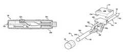
- FIG. 8is a perspective view of a second embodiment of the invention.
- FIG. 9is a somewhat schematic longitudinal cross-sectional view of the lancing device of FIG. 8 ;
- FIG. 10is a somewhat schematic cross-sectional view taken on line 10 - 10 of FIG. 9 ;
- FIG. 11is a perspective view of a third embodiment of the invention.
- FIG. 12is a somewhat schematic cross-sectional view of the lancing device of FIG. 11 .
- the lancing device 10 seen in FIGS. 1-7broadly considered, includes a housing 12 , a lancet 16 , a lancet holder 18 , a cocking mechanism 20 and a trigger mechanism 22 .
- Housing 10includes a main body housing member 24 and a front cap 26 .
- Main body housing member 24is elongated, has a generally rectangular cross-sectional configuration, and includes a top wall 24 a , a bottom wall 24 b , side walls 24 c , 24 d and a rear end wall 24 e .
- Top wall 24 aincludes an aperture 24 f to accommodate the trigger mechanism.
- Front cap 26is sized to be secured to the front end of housing member 24 and includes a front wall 26 a defining a piercing aperture 26 b.
- Lancet 16is of known form and includes a generally cylindrical body 16 a carrying one or more needles 16 b.
- Lancet holder 18comprises a rod suitably mounted for axial movement in the housing and having a notch 18 a.
- Cocking mechanism 20includes a button 28 mounted in housing end wall 24 e for inward and outward movement relative to the housing end wall and an actuator 30 .
- Actuator 30includes a rearward rod portion 30 a , a forward guide portion 30 b and a central resilient portion 30 c.
- the rear end 30 b of rod portion 36is fixedly secured in a socket 28 a of button 28 .
- Guide portion 30 bhas a generally planar configuration.
- Resilient portion 30 cincludes an upper resilient arm 30 e interconnecting rod portion 30 a and guide portion 30 b and a lower resilient arm structure 30 f further interconnecting rod portion 30 a and guide portion 30 b .
- Lower resilient arm structure 30 fdefines a button 30 g and is bifurcated at its forward end to form a window 30 h to accommodate axial movement of lancet holder 18 .
- Trigger mechanism 22is in the form of a trigger button sized to fit in housing aperture 24 f and defining guide structure 22 a on the underface of the button for slidable receipt of guide portion 30 b of actuator 30 .
- button 28is slidably received in end wall 24 e
- lancet 16is suitably mounted on the front end of lancet holder 18
- the rear end of actuator rod portion 30 ais coupled to button 28
- the front planar guide portion 30 b of actuator 30is slidably received in guide structure 22 a of trigger 22
- button 30 gis resiliently positioned proximate the underside of lancet holder 18 .
- Lancet holder 18is suitably slidably guided in housing 12 for axial movement between a retracted position seen in FIGS. 2 , 3 and 6 , a cocked position seen in FIG. 4 , and an operative puncturing position seen in FIG. 5 .
- button 28is slidably mounted in housing end wall 24 e , the upper face 22 b of trigger 22 is flush with the upper face of housing upper wall 24 a , and button 30 g of actuator 30 is resiliently pressed against the underface of lancet holder 18 rearwardly of notch 18 a.
- button 28has been pressed inwardly or forwardly to move button 30 g into alignment with notch 18 a with this forward movement of the actuator accommodated by sliding movement of actuator guide portion 30 b in trigger guide structure 22 a.
- This rearward movement of the lancet holderis accompanied by compression of a suitable compression spring mechanism such as shown schematically at 34 , the spring device 34 being understood to exert a lesser biasing force than the spring 32 so as not to impede the rearward movement of the actuator and the lancet holder under the bias of spring 32 .
- trigger 22may be depressed as seen in FIG. 5 to resiliently displace knob 13 g from notch 13 a and allow the lancet holder and lancet to be fired forwardly under the impetus of spring device 34 to achieve the piercing or puncture position of FIG. 5 wherein a needle 16 b extends marginally forwardly of the front wall 26 a of cap 26 to achieve the patient piercing function whereafter the lancet and lancet holder retreat to the retracted position seen in FIG. 6 , corresponding to the initial position of FIG. 2 .
- actuator 30 and button 28undergo a slight rebound movement but thereafter return to their initial retracted position of FIGS. 2 and 6 .
- the lancing device of the FIGS. 1-7 of the embodimentwill be seen to provide a simple effective and inexpensive cocking mechanism.
- the lancing device 40 of the FIGS. 8-10 embodimentbroadly considered, includes a housing 42 , a lancet 16 , a lancet holder 44 , a cocking mechanism 46 , and a trigger mechanism 48 .
- Housing mechanism 42includes a main body housing member 50 and a front cap 52 defining a piercing aperture 52 a.
- Main body housing member 24includes a top wall 50 a , a bottom wall 50 b , side walls 50 c , 50 d , and an end wall 50 e .
- Top wall 50 aincludes an aperture 50 f to accommodate trigger mechanism 48 .
- Main body housing member 50defines a lancet storage compartment 50 g defined by end wall 50 e , a longitudinal partition 50 h , a transverse partition 50 i , and overlying and underlying portions 50 a , 50 b of top wall 50 a and bottom wall 50 b , respectively.
- compartment 50 gis of a size to accommodate a large plurality of lancets 16 .
- Main body housing member 50further defines a door 54 pivotally mounted about a vertical axis 56 proximate a rear end of the lancing device for movement between an open position, as seen in FIGS. 8 and 9 and a closed position in which access to the lancets is precluded.
- Lancet holder 44has a rod configuration and includes a detent notch 44 a and a radial arm 44 b.
- Lancet holder 44is suitably mounted for axial movement within housing 42 between a retracted position seen in solid lines, a cocked position, and an operative or piercing position.
- Cocking mechanism 46includes an arcuate rack 60 and a pinion 62 mounted for rotation in housing member 50 by a post 50 j and having an eccentric portion 62 a for coaction with radial arm 44 b of lancet holder 44 .
- Trigger mechanism 48is schematically illustrated and may, for example, include a trigger member 66 positioned in housing aperture 50 f and a detent mechanism 68 biased downwardly against lancet holder 44 via a suitable spring mechanism 70 .
- a trigger member 66positioned in housing aperture 50 f
- a detent mechanism 68biased downwardly against lancet holder 44 via a suitable spring mechanism 70 .
- closing movement of door 54has the effect of moving the lancet holder to its cocked position.
- arcuate rack 60meshingly engages pinion 62 to rotate the pinion and bring eccentric portions 62 a into engagement with lancet holder radial arm 44 b to move the lancet holder rearwardly within the housing against the resistance of a coil spring 72 .
- the parameters of the deviceare chosen such that as eccentric portion 62 a clears radial arm 44 b , detent 68 moves into detented engagement with notch 44 a so that the lancet holder is held in its cocked position whereafter, upon depression of trigger mechanism 66 to release detent 68 from engagement with notch 44 a , the lancet holder is free to move forwardly under the urging of spring 72 to achieve the piercing position.
- the lancing device of the FIGS. 8-10 embodimentwill be seen to provide a convenient arrangement for storing lancets, allow access to the storage compartment to be coordinated with cocking of the lancet holder, and provide a safety feature in the sense that unauthorized or inadvertent access to the stored lancets is discouraged by requiring a specific user operation to allow unlocking of the access door to the lancet storage compartment.
- the lancing device of the FIGS. 11 and 12 embodimentis generally similar to the FIG. 8-10 embodiment with the exception that the lancet storage compartment, rather than being defined within the housing by walls of the housing, is defined as an integral part of the door 54 and moves inwardly and outwardly with the door.
- the lancet storage compartment 80 of the FIGS. 11 and 12 embodimentis constituted as a drawer carried by the door 54 and is defined by the door, as the drawer face, by a floor 82 , an arcuate end wall 84 , and a partition 86 .
- the lancets positioned in the storage compartment 80are moved outwardly of the housing to a position wherein they can be readily accessed from the open upper end of compartment 80 .
- a method of cocking the lancing device 40 disclosed with reference to FIGS. 8-12comprises opening a door 54 of the storage compartment 50 g to remove or deposit one or more of the plurality of lancets 16 and closing the door 54 of the storage compartment 50 g to cock the lancing device 40 , wherein closing the door 54 of the storage compartment 50 g moves the lancet holder 44 from a neutral position to a cocked position.
- the step of closing the doorcan operate a cocking mechanism 46 , for example, having a rack mounted within the housing on the door and a pinion driven by the rack engaging the lancet holder.
- the door 54can be configured to pivot between the open and closed positions.
- the door 54can be further configured to pivot about an axis on one edge of the door proximate a rear end wall of the housing.
- the lancet storage compartment 50 gcan be a drawer and the door 54 can be the drawer face.
Landscapes
- Health & Medical Sciences (AREA)
- Life Sciences & Earth Sciences (AREA)
- Engineering & Computer Science (AREA)
- Heart & Thoracic Surgery (AREA)
- Molecular Biology (AREA)
- Physics & Mathematics (AREA)
- Veterinary Medicine (AREA)
- Biophysics (AREA)
- Pathology (AREA)
- Biomedical Technology (AREA)
- Public Health (AREA)
- Medical Informatics (AREA)
- Hematology (AREA)
- Surgery (AREA)
- Animal Behavior & Ethology (AREA)
- General Health & Medical Sciences (AREA)
- Diabetes (AREA)
- Manufacturing & Machinery (AREA)
- Dermatology (AREA)
- Measurement Of The Respiration, Hearing Ability, Form, And Blood Characteristics Of Living Organisms (AREA)
Abstract
Description
Claims (13)
Priority Applications (1)
| Application Number | Priority Date | Filing Date | Title |
|---|---|---|---|
| US13/222,242US8366730B2 (en) | 2008-08-14 | 2011-08-31 | Cocking mechanism for lancing device |
Applications Claiming Priority (2)
| Application Number | Priority Date | Filing Date | Title |
|---|---|---|---|
| US12/191,879US8029526B2 (en) | 2008-08-14 | 2008-08-14 | Cocking mechanism for lancing device |
| US13/222,242US8366730B2 (en) | 2008-08-14 | 2011-08-31 | Cocking mechanism for lancing device |
Related Parent Applications (1)
| Application Number | Title | Priority Date | Filing Date |
|---|---|---|---|
| US12/191,879DivisionUS8029526B2 (en) | 2008-08-14 | 2008-08-14 | Cocking mechanism for lancing device |
Publications (2)
| Publication Number | Publication Date |
|---|---|
| US20110319919A1 US20110319919A1 (en) | 2011-12-29 |
| US8366730B2true US8366730B2 (en) | 2013-02-05 |
Family
ID=41202496
Family Applications (2)
| Application Number | Title | Priority Date | Filing Date |
|---|---|---|---|
| US12/191,879Expired - Fee RelatedUS8029526B2 (en) | 2008-08-14 | 2008-08-14 | Cocking mechanism for lancing device |
| US13/222,242Expired - Fee RelatedUS8366730B2 (en) | 2008-08-14 | 2011-08-31 | Cocking mechanism for lancing device |
Family Applications Before (1)
| Application Number | Title | Priority Date | Filing Date |
|---|---|---|---|
| US12/191,879Expired - Fee RelatedUS8029526B2 (en) | 2008-08-14 | 2008-08-14 | Cocking mechanism for lancing device |
Country Status (2)
| Country | Link |
|---|---|
| US (2) | US8029526B2 (en) |
| WO (1) | WO2010019741A1 (en) |
Families Citing this family (42)
| Publication number | Priority date | Publication date | Assignee | Title |
|---|---|---|---|---|
| BRPI0817907B8 (en) | 2007-10-02 | 2021-06-22 | Lamodel Ltd | apparatus for administering a substance to an individual |
| US7967795B1 (en) | 2010-01-19 | 2011-06-28 | Lamodel Ltd. | Cartridge interface assembly with driving plunger |
| US10420880B2 (en) | 2007-10-02 | 2019-09-24 | West Pharma. Services IL, Ltd. | Key for securing components of a drug delivery system during assembly and/or transport and methods of using same |
| US9345836B2 (en) | 2007-10-02 | 2016-05-24 | Medimop Medical Projects Ltd. | Disengagement resistant telescoping assembly and unidirectional method of assembly for such |
| US9656019B2 (en) | 2007-10-02 | 2017-05-23 | Medimop Medical Projects Ltd. | Apparatuses for securing components of a drug delivery system during transport and methods of using same |
| US12097357B2 (en) | 2008-09-15 | 2024-09-24 | West Pharma. Services IL, Ltd. | Stabilized pen injector |
| US9393369B2 (en) | 2008-09-15 | 2016-07-19 | Medimop Medical Projects Ltd. | Stabilized pen injector |
| US10071196B2 (en) | 2012-05-15 | 2018-09-11 | West Pharma. Services IL, Ltd. | Method for selectively powering a battery-operated drug-delivery device and device therefor |
| US8157769B2 (en) | 2009-09-15 | 2012-04-17 | Medimop Medical Projects Ltd. | Cartridge insertion assembly for drug delivery system |
| US10071198B2 (en) | 2012-11-02 | 2018-09-11 | West Pharma. Servicees IL, Ltd. | Adhesive structure for medical device |
| US8348898B2 (en) | 2010-01-19 | 2013-01-08 | Medimop Medical Projects Ltd. | Automatic needle for drug pump |
| EP2569031B1 (en) | 2010-05-10 | 2017-10-11 | Medimop Medical Projects Ltd. | Low volume accurate injector |
| USD702834S1 (en) | 2011-03-22 | 2014-04-15 | Medimop Medical Projects Ltd. | Cartridge for use in injection device |
| EP2809375B1 (en) | 2012-01-31 | 2021-08-11 | Medimop Medical Projects Ltd. | Time dependent drug delivery apparatus |
| US10668213B2 (en) | 2012-03-26 | 2020-06-02 | West Pharma. Services IL, Ltd. | Motion activated mechanisms for a drug delivery device |
| US9463280B2 (en) | 2012-03-26 | 2016-10-11 | Medimop Medical Projects Ltd. | Motion activated septum puncturing drug delivery device |
| US9072827B2 (en) | 2012-03-26 | 2015-07-07 | Medimop Medical Projects Ltd. | Fail safe point protector for needle safety flap |
| EP2836123B1 (en)* | 2012-04-09 | 2017-05-10 | Facet Technologies, LLC | Push-to-charge lancing device |
| EP2836125B1 (en) | 2012-04-12 | 2016-06-08 | Facet Technologies, LLC | Lancing device with side activated charge and eject mechanisms |
| DE102012019404B4 (en)* | 2012-10-04 | 2015-12-31 | Gerresheimer Regensburg Gmbh | Lancing device for blood sampling |
| US9421323B2 (en) | 2013-01-03 | 2016-08-23 | Medimop Medical Projects Ltd. | Door and doorstop for portable one use drug delivery apparatus |
| WO2014116688A1 (en)* | 2013-01-23 | 2014-07-31 | Facet Technologies, Llc | Push-to-charge lancing device |
| US9011164B2 (en) | 2013-04-30 | 2015-04-21 | Medimop Medical Projects Ltd. | Clip contact for easy installation of printed circuit board PCB |
| US9889256B2 (en) | 2013-05-03 | 2018-02-13 | Medimop Medical Projects Ltd. | Sensing a status of an infuser based on sensing motor control and power input |
| US9795534B2 (en) | 2015-03-04 | 2017-10-24 | Medimop Medical Projects Ltd. | Compliant coupling assembly for cartridge coupling of a drug delivery device |
| US10251813B2 (en) | 2015-03-04 | 2019-04-09 | West Pharma. Services IL, Ltd. | Flexibly mounted cartridge alignment collar for drug delivery device |
| US10293120B2 (en) | 2015-04-10 | 2019-05-21 | West Pharma. Services IL, Ltd. | Redundant injection device status indication |
| US9744297B2 (en) | 2015-04-10 | 2017-08-29 | Medimop Medical Projects Ltd. | Needle cannula position as an input to operational control of an injection device |
| US10149943B2 (en) | 2015-05-29 | 2018-12-11 | West Pharma. Services IL, Ltd. | Linear rotation stabilizer for a telescoping syringe stopper driverdriving assembly |
| CN113181477B (en) | 2015-06-04 | 2023-07-14 | 麦迪麦珀医疗工程有限公司 | Cartridge insertion for drug delivery device |
| US10576207B2 (en) | 2015-10-09 | 2020-03-03 | West Pharma. Services IL, Ltd. | Angled syringe patch injector |
| US9987432B2 (en) | 2015-09-22 | 2018-06-05 | West Pharma. Services IL, Ltd. | Rotation resistant friction adapter for plunger driver of drug delivery device |
| US11318254B2 (en) | 2015-10-09 | 2022-05-03 | West Pharma. Services IL, Ltd. | Injector needle cap remover |
| JP6885960B2 (en) | 2016-01-21 | 2021-06-16 | ウェスト ファーマ サービシーズ イスラエル リミテッド | Drug delivery device with visual indicators |
| US10646643B2 (en) | 2016-01-21 | 2020-05-12 | West Pharma. Services IL, Ltd. | Needle insertion and retraction mechanism |
| EP3711793B1 (en) | 2016-01-21 | 2021-12-01 | West Pharma Services IL, Ltd. | A method of connecting a cartridge to an automatic injector |
| US11389597B2 (en) | 2016-03-16 | 2022-07-19 | West Pharma. Services IL, Ltd. | Staged telescopic screw assembly having different visual indicators |
| CN109310831B (en) | 2016-06-02 | 2021-11-23 | 西医药服务以色列有限公司 | Three position needle retraction |
| JP7059251B2 (en) | 2016-08-01 | 2022-04-25 | ウェスト ファーマ サービシーズ イスラエル リミテッド | A spring that prevents the door from closing halfway |
| US11338090B2 (en) | 2016-08-01 | 2022-05-24 | West Pharma. Services IL, Ltd. | Anti-rotation cartridge pin |
| EP3630226A1 (en) | 2017-05-30 | 2020-04-08 | West Pharma. Services Il, Ltd. | Modular drive train for wearable injector |
| JP7402799B2 (en) | 2017-12-22 | 2023-12-21 | ウェスト ファーマ サービシーズ イスラエル リミテッド | Syringes available with different cartridge sizes |
Citations (2)
| Publication number | Priority date | Publication date | Assignee | Title |
|---|---|---|---|---|
| US6156051A (en)* | 1998-06-11 | 2000-12-05 | Stat Medical Devices Inc. | Lancet having adjustable penetration depth |
| US20080195132A1 (en)* | 2007-02-08 | 2008-08-14 | Stat Medical Devices, Inc. | Push-button lance device and method |
Family Cites Families (47)
| Publication number | Priority date | Publication date | Assignee | Title |
|---|---|---|---|---|
| CH500707A (en) | 1968-07-26 | 1970-12-31 | Micromedic Systems Inc | Device for performing percutaneous and digital blood sampling |
| US4577630A (en) | 1984-02-14 | 1986-03-25 | Becton, Dickinson And Co. | Reusable breach loading target pressure activated lancet firing device |
| US4895147A (en) | 1988-10-28 | 1990-01-23 | Sherwood Medical Company | Lancet injector |
| DE4212315A1 (en) | 1992-04-13 | 1993-10-14 | Boehringer Mannheim Gmbh | Blood lancet device for drawing blood for diagnostic purposes |
| SE9502285D0 (en) | 1995-06-22 | 1995-06-22 | Pharmacia Ab | Improvements related to injections |
| WO1997004707A1 (en) | 1995-07-28 | 1997-02-13 | Apls Co., Ltd. | Assembly for adjusting piercing depth of lancet |
| US6015392A (en) | 1996-05-17 | 2000-01-18 | Mercury Diagnostics, Inc. | Apparatus for sampling body fluid |
| US5613978A (en) | 1996-06-04 | 1997-03-25 | Palco Laboratories | Adjustable tip for lancet device |
| US5741288A (en) | 1996-06-27 | 1998-04-21 | Chemtrak, Inc. | Re-armable single-user safety finger stick device having reset for multiple use by a single patient |
| US5984940A (en) | 1997-05-29 | 1999-11-16 | Atrion Medical Products, Inc. | Lancet device |
| US5944700A (en) | 1997-09-26 | 1999-08-31 | Becton, Dickinson And Company | Adjustable injection length pen needle |
| US5871494A (en) | 1997-12-04 | 1999-02-16 | Hewlett-Packard Company | Reproducible lancing for sampling blood |
| US6036924A (en) | 1997-12-04 | 2000-03-14 | Hewlett-Packard Company | Cassette of lancet cartridges for sampling blood |
| US6949111B2 (en) | 1998-02-13 | 2005-09-27 | Steven Schraga | Lancet device |
| US5908434A (en) | 1998-02-13 | 1999-06-01 | Schraga; Steven | Lancet device |
| US6346114B1 (en) | 1998-06-11 | 2002-02-12 | Stat Medical Devices, Inc. | Adjustable length member such as a cap of a lancet device for adjusting penetration depth |
| US7175641B1 (en) | 1998-06-11 | 2007-02-13 | Stat Medical Devices, Inc. | Lancet having adjustable penetration depth |
| US6045567A (en) | 1999-02-23 | 2000-04-04 | Lifescan Inc. | Lancing device causing reduced pain |
| US6558402B1 (en) | 1999-08-03 | 2003-05-06 | Becton, Dickinson And Company | Lancer |
| US6283982B1 (en) | 1999-10-19 | 2001-09-04 | Facet Technologies, Inc. | Lancing device and method of sample collection |
| US6228100B1 (en) | 1999-10-25 | 2001-05-08 | Steven Schraga | Multi-use lancet device |
| US6530937B1 (en) | 2000-01-28 | 2003-03-11 | Stat Medical Devices, Inc. | Adjustable tip for a lancet device and method |
| TW495353B (en) | 2000-09-01 | 2002-07-21 | Bayer Ag | Adjustable endcap for lancing device |
| CN1313052C (en) | 2001-01-12 | 2007-05-02 | 爱科来株式会社 | piercing device |
| US6645219B2 (en) | 2001-09-07 | 2003-11-11 | Amira Medical | Rotatable penetration depth adjusting arrangement |
| US20030100913A1 (en) | 2001-10-09 | 2003-05-29 | Guoping Shi | Depth adjustable cap of lancing device |
| US7357808B2 (en) | 2002-01-31 | 2008-04-15 | Facet Technologies, Llc | Single use device for blood microsampling |
| KR200283543Y1 (en) | 2002-04-22 | 2002-07-26 | 김용필 | Automatic Lancing Device |
| DE10223558A1 (en) | 2002-05-28 | 2003-12-11 | Roche Diagnostics Gmbh | System useful in withdrawing blood for diagnostic purposes, has housing, lancet guide and lancet drive provided with drive spring, cocking device, drive rotor and outputs side coupling mechanism |
| JP3650819B2 (en) | 2002-07-15 | 2005-05-25 | 独立行政法人産業技術総合研究所 | Cutting method of carbon nanotube |
| US6852119B1 (en) | 2002-09-09 | 2005-02-08 | Ramzi F. Abulhaj | Adjustable disposable lancet and method |
| FR2845266B1 (en) | 2002-10-03 | 2004-12-17 | Porges Sa | DEVICE FOR TAKING A BODY SAMPLE |
| JPWO2004043258A1 (en)* | 2002-10-28 | 2006-03-09 | 積水化学工業株式会社 | Puncture tool |
| US20040127818A1 (en) | 2002-12-27 | 2004-07-01 | Roe Steven N. | Precision depth control lancing tip |
| US7621931B2 (en) | 2003-05-20 | 2009-11-24 | Stat Medical Devices, Inc. | Adjustable lancet device and method |
| DE10336933B4 (en) | 2003-08-07 | 2007-04-26 | Roche Diagnostics Gmbh | Blood Collection system |
| US7105006B2 (en) | 2003-08-15 | 2006-09-12 | Stat Medical Devices, Inc. | Adjustable lancet device and method |
| US7905898B2 (en) | 2003-08-15 | 2011-03-15 | Stat Medical Devices, Inc. | Adjustable lancet device and method |
| WO2005018454A2 (en) | 2003-08-20 | 2005-03-03 | Facet Technologies, Llc | Multi-lancet device with sterility cap repositioning mechanism |
| EP1684634A2 (en) | 2003-11-12 | 2006-08-02 | Facet Technologies, LLC | Lancing device and multi-lancet cartridge |
| US20070156225A1 (en)* | 2003-12-23 | 2007-07-05 | Xtent, Inc. | Automated control mechanisms and methods for custom length stent apparatus |
| US20050159768A1 (en) | 2004-01-15 | 2005-07-21 | Home Diagnostics, Inc. | Lancing device |
| US7837633B2 (en) | 2004-06-30 | 2010-11-23 | Facet Technologies, Llc | Lancing device and multi-lancet cartridge |
| CN101179991B (en) | 2005-04-07 | 2010-11-03 | 贝克顿·迪金森公司 | Push activation lancet device |
| US20070083222A1 (en) | 2005-06-16 | 2007-04-12 | Stat Medical Devices, Inc. | Lancet device, removal system for lancet device, and method |
| US7775991B2 (en) | 2005-08-31 | 2010-08-17 | Kimberly-Clark Worldwide, Inc. | Device for sampling blood |
| GB2434103B (en) | 2006-01-12 | 2009-11-25 | Owen Mumford Ltd | Lancet firing device |
- 2008
- 2008-08-14USUS12/191,879patent/US8029526B2/ennot_activeExpired - Fee Related
- 2009
- 2009-08-13WOPCT/US2009/053652patent/WO2010019741A1/enactiveApplication Filing
- 2011
- 2011-08-31USUS13/222,242patent/US8366730B2/ennot_activeExpired - Fee Related
Patent Citations (2)
| Publication number | Priority date | Publication date | Assignee | Title |
|---|---|---|---|---|
| US6156051A (en)* | 1998-06-11 | 2000-12-05 | Stat Medical Devices Inc. | Lancet having adjustable penetration depth |
| US20080195132A1 (en)* | 2007-02-08 | 2008-08-14 | Stat Medical Devices, Inc. | Push-button lance device and method |
Also Published As
| Publication number | Publication date |
|---|---|
| US20100042131A1 (en) | 2010-02-18 |
| US20110319919A1 (en) | 2011-12-29 |
| US8029526B2 (en) | 2011-10-04 |
| WO2010019741A1 (en) | 2010-02-18 |
Similar Documents
| Publication | Publication Date | Title |
|---|---|---|
| US8366730B2 (en) | Cocking mechanism for lancing device | |
| US6197040B1 (en) | Lancing device having a releasable connector | |
| US8568434B2 (en) | Lancing device | |
| EP2187811B1 (en) | Lancing devices | |
| US6045567A (en) | Lancing device causing reduced pain | |
| US7144404B2 (en) | Lancing device | |
| US8574255B2 (en) | Narrow-profile lancing device | |
| EP1219242B1 (en) | Body fluid sampling apparatus | |
| EP2050393B1 (en) | Lancing device | |
| US9078604B2 (en) | Lancing devices | |
| US8308748B2 (en) | Collapsible lancing device | |
| CN101518450B (en) | piercing device | |
| EP2381847B1 (en) | Skin pricking device | |
| JPH08140980A (en) | Biopsy device | |
| MXPA00001859A (en) | Lancing device having a releasable connector |
Legal Events
| Date | Code | Title | Description |
|---|---|---|---|
| AS | Assignment | Owner name:FACET TECHNOLOGIES, LLC, GEORGIA Free format text:ASSIGNMENT OF ASSIGNORS INTEREST;ASSIGNOR:LATHROP, RAY ADAMS;REEL/FRAME:026837/0129 Effective date:20080930 Owner name:ABBOTT DIABETES CARE INC., CALIFORNIA Free format text:ASSIGNMENT OF ASSIGNORS INTEREST;ASSIGNOR:FACET TECHNOLOGIES, LLC;REEL/FRAME:026837/0470 Effective date:20080922 Owner name:ABBOTT DIABETES CARE INC., CALIFORNIA Free format text:ASSIGNMENT OF ASSIGNORS INTEREST;ASSIGNOR:CURRY, SAMUEL MASON;REEL/FRAME:026837/0009 Effective date:20080805 | |
| STCF | Information on status: patent grant | Free format text:PATENTED CASE | |
| FPAY | Fee payment | Year of fee payment:4 | |
| FEPP | Fee payment procedure | Free format text:MAINTENANCE FEE REMINDER MAILED (ORIGINAL EVENT CODE: REM.); ENTITY STATUS OF PATENT OWNER: LARGE ENTITY | |
| LAPS | Lapse for failure to pay maintenance fees | Free format text:PATENT EXPIRED FOR FAILURE TO PAY MAINTENANCE FEES (ORIGINAL EVENT CODE: EXP.); ENTITY STATUS OF PATENT OWNER: LARGE ENTITY | |
| STCH | Information on status: patent discontinuation | Free format text:PATENT EXPIRED DUE TO NONPAYMENT OF MAINTENANCE FEES UNDER 37 CFR 1.362 | |
| FP | Lapsed due to failure to pay maintenance fee | Effective date:20210205 |