US8366720B2 - Interventional medical device system having an elongation retarding portion and method of using the same - Google Patents
Interventional medical device system having an elongation retarding portion and method of using the sameDownload PDFInfo
- Publication number
- US8366720B2 US8366720B2US11/461,231US46123106AUS8366720B2US 8366720 B2US8366720 B2US 8366720B2US 46123106 AUS46123106 AUS 46123106AUS 8366720 B2US8366720 B2US 8366720B2
- Authority
- US
- United States
- Prior art keywords
- proximal
- distal
- helical
- helical section
- section
- Prior art date
- Legal status (The legal status is an assumption and is not a legal conclusion. Google has not performed a legal analysis and makes no representation as to the accuracy of the status listed.)
- Active, expires
Links
Images


Classifications
- A—HUMAN NECESSITIES
- A61—MEDICAL OR VETERINARY SCIENCE; HYGIENE
- A61B—DIAGNOSIS; SURGERY; IDENTIFICATION
- A61B17/00—Surgical instruments, devices or methods
- A61B17/12—Surgical instruments, devices or methods for ligaturing or otherwise compressing tubular parts of the body, e.g. blood vessels or umbilical cord
- A61B17/12022—Occluding by internal devices, e.g. balloons or releasable wires
- A61B2017/1205—Introduction devices
- A61B2017/12054—Details concerning the detachment of the occluding device from the introduction device
- A—HUMAN NECESSITIES
- A61—MEDICAL OR VETERINARY SCIENCE; HYGIENE
- A61B—DIAGNOSIS; SURGERY; IDENTIFICATION
- A61B90/00—Instruments, implements or accessories specially adapted for surgery or diagnosis and not covered by any of the groups A61B1/00 - A61B50/00, e.g. for luxation treatment or for protecting wound edges
- A61B90/03—Automatic limiting or abutting means, e.g. for safety
- A61B2090/037—Automatic limiting or abutting means, e.g. for safety with a frangible part, e.g. by reduced diameter
Definitions
- This inventiongenerally relates to interventional medical device systems that are navigable through body vessels of a human subject. More particularly, this invention relates to tubular devices having a frangible elongation retarding feature and methods of using the same.
- catheter delivery systemsfor positioning and deploying therapeutic devices, such as dilation balloons, stents and embolic coils, in the vasculature of the human body has become a standard procedure for treating vascular diseases. It has been found that such devices are particularly useful in treating areas where traditional operational procedures are impossible or pose a great risk to the patient, for example in the treatment of intracranial aneurysms. Due to the delicate tissue surrounding intracranial blood vessels, especially for example brain tissue, it is very difficult and often risky to perform surgical procedures to treat defects of the intracranial blood vessels. Advancements in catheter deployment systems have provided an alternative treatment in such cases. Some of the advantages of catheter delivery systems are that they provide methods for treating blood vessels by an approach that has been found to reduce the risk of trauma to the surrounding tissue, and they also allow for treatment of blood vessels that in the past would have been considered inoperable.
- these proceduresinvolve inserting the distal end of a delivery catheter into the vasculature of a patient and guiding it through the vasculature to a predetermined delivery site.
- a vascular occlusion devicesuch as an embolic coil
- embolic coilis attached to the end of a delivery member which pushes the coil through the catheter and out of the distal end of the catheter into the delivery site.
- Another coil deployment systememploys a pusher member having an embolic coil attached to the pusher member by a connector fiber which is capable of being broken by heat, as disclosed in Lucas et al. U.S. Pat. No. 6,478,773.
- the pusher member of this arrangementincludes an electrical resistance heating coil through which the connector fiber is passed. Electrical current is supplied to the heating coil by a power source connected to the heating coil via wires extending through an internal lumen of the pusher. The power source is activated to increase the temperature of the heating coil which breaks the connector fiber.
- One drawbackis that connecting the resistance heating coil to the power source requires running multiple wires through the pusher member. Additionally, the electrical current traveling through the wires may create stray electromagnetic fields that have the potential to interfere with other surgical and monitoring equipment.
- the above-identified delivery systemstypically require electronic equipment powered by a power source. If the electronic equipment is defective or the power source fails, the procedure may be prolonged while the equipment is repaired or replaced. Prolonging the procedure may expose the patient to additional risk.
- a separate handle componentsuch as an attachable handle, a peelable sheath system, a syringe, that is manipulated by the medical professional to release the implantable device.
- Attachable handle componentsoften require the use of additional components, such as a re-zip sheath, for proper operation including as an introducer component. This tends to increase the time and complexity of releasing the implantable device, as well as increasing the component and packaging costs.
- a needremains for a rapid release vascular occlusion deployment system or method that can function without electrical equipment or a power supply, does not develop chemical debris, is simple to manufacture, flexible and easy to guide through the vasculature of the body, provides excellent control over the occlusion device, and reduces the possibility of interference with other surgical and/or monitoring equipment. Further advantages could be realized with a handle system that has a low profile such as having the same outer diameter dimension as the overall delivery system.
- an interventional medical device system operable while within a body vesselis provided with a generally hollow tubular proximal portion, distal portion, and intermediate portion.
- the proximal portionremains outside of the body in use, while at least a portion of the distal portion is positioned within the body during use.
- the intermediate portionwhich typically remains outside of the body during use of the system, includes a spiral ribbon having adjacent turns, with at least one frangible bridge member between two adjacent turns. The proximal and distal portions are movable away from each other by elongating the spiral ribbon and, eventually, breaking the frangible bridge member.
- an interventional medical device system operable while within a body vesselis provided with a proximal portion handle, a distal portion, and an intermediate portion. At least a portion of the distal portion is positioned within the body during use.
- the intermediate portionincludes a proximal helical section adjacent to the proximal handle portion, a distal helical section adjacent to the distal portion, and an intermediate helical section between the other two helical sections.
- the intermediate helical sectionincludes a plurality of adjacent turns, with a frangible bridge member between two adjacent turns. The proximal and distal portions are movable away from each other by elongating the intermediate portion and, eventually, breaking the frangible bridge member.
- an actuation memberis connected to the proximal portion, and an implantable medical device is associated with a deployment end of the actuation member. Movement of the proximal portion of the system away from the distal portion disengages the implantable device at a target location within the vasculature. The bridge member retards axial extension of the turns for improved control when releasing the implantable device.
- a method of using an interventional medical device system in a body vesselincludes providing a generally hollow tubular system.
- the tubular systemincludes a distal end portion, a proximal end handle portion, an intermediate portion, and an actuation member.
- the intermediate portioncomprises a spiral having a plurality of turns and at least one bridge member between two adjacent turns.
- the actuation memberis fixedly connected to the proximal end handle portion and extends to the distal end portion of the system. At least a portion of the distal end portion of the system is introduced into a body vessel and positioned generally adjacent to a target location within the vessel.
- proximal end handle portionis then moved proximally with respect to the distal end portion, thereby breaking the bridge member and proximally moving the actuation member. If provided, an implantable medical device associated with a deployment end portion of the actuation member is released into the target location upon proximal movement of the actuation member.
- FIG. 1is a front elevational view of a medical device portion according to an aspect of the present invention, in a pre-actuation condition;
- FIG. 2is a front elevational view of the medical device portion of FIG. 1 , in a post-actuation condition;
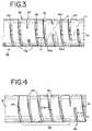
- FIG. 3is a detail view of an intermediate helical section of the medical device portion of FIG. 1 ;
- FIG. 4is a detail view of a proximal helical section of the medical device portion of FIG. 1 .
- FIGS. 1 and 2illustrate a generally hollow or tubular structure according to the present invention.
- tubularand “tube” are to be construed broadly and are not limited to a structure that is a right cylinder or strictly circumferential in cross-section or of a uniform cross-section throughout its length.
- the tubular device or systemis generally designated at 10 and shown as a substantially right cylindrical structure.
- the tubular systemmay have a tapered or curved outer surface without departing from the scope of the present invention.
- a proximal portion 12 of the system 10may be used as a handle to manipulate the system 10 , so it may be relatively large, tapered, and/or otherwise shaped for improved gripping without departing from the scope of the present invention.
- the system 10is comprised of a generally hollow tubular proximal portion or proximal portion handle or proximal end handle portion 12 , distal portion or distal end portion 14 , and intermediate portion 16 .
- the proximal and distal portions 12 and 14are substantially non-compressible, non-elongatable metal hypotubes or portions of the same single hypotube.
- the intermediate portion 16includes a plurality of spiral turns 18 and is elongatable, as illustrated in FIGS. 1 and 2 .
- the system 10is provided as an elongated metal hypotube, with the intermediate portion 16 comprising a spiral-cut portion thereof. The structure of the intermediate portion 16 is described in greater detail herein.
- the proximal portion 12remains outside of the body during use and may be used as a handle of the system 10 to be gripped and manipulated by a user.
- the proximal portion 12may include a plug member 20 fixedly connected to an anchored end 22 of an elongated actuation member 24 , which actuation member 24 extends at least from an interior lumen of the proximal portion 12 to an interior lumen of the distal portion 14 .
- the actuation member 24may be comprised of a metal or polymer and formed as a wire, tube, or other elongated structure.
- the anchored end 22may be connected to the plug member 20 by any suitable means, including (but not limited to) adhesive, metallic bonding, and heat fusing. The function of the actuation member 24 is described in greater detail herein.
- the distal portion 14 of the system 10is adapted to be received by a body vessel. It will be appreciated that only a small section of the distal portion 14 is illustrated in FIGS. 1 and 2 , as the distal portion 14 is preferably relatively lengthy with respect to the proximal portion 12 , so that it can extend through the vasculature to reach a target location.
- the system 10has a length in the range of approximately 180 and 200 cm, with the proximal portion 12 and the intermediate portion 16 collectively accounting for approximately 15 cm of the total length.
- the actuation member 24extends into an interior lumen of the distal portion 14 , with a deployment end (not illustrated) of the actuation member 24 adjacent to or extending beyond the end of the distal portion 14 .
- the proximal and distal portions 12 and 14are separated by the intermediate portion 16 , which preferably remains outside of the body during use. Sections of a preferred intermediate portion 16 are shown in greater detail in FIGS. 3 and 4 .
- the intermediate portion 16includes at least an interrupted spiral section 26 ( FIG. 3 ), also referred to herein as an intermediate helical section.
- the intermediate helical section 26comprises a spiral ribbon 28 having adjacent turns 18 , similar to a typical wound wire or spiral-cut tube. However, while the turns of a typical wound wire or spiral-cut tube are defined and separated by a continuous helical opening, the turns 18 of the intermediate helical section 26 are separated by an interrupted spiral 30 .
- the interrupted spiralis characterized by an open or cut section 32 and at least one uncut section or frangible bridge member 34 between two adjacent turns 18 .
- the intermediate helical section 26includes a plurality of alternating cut and uncut sections 32 and 34 .
- the alternating cut and uncut sections 32 and 34preferably define a single substantially helical pattern, which may simplify manufacture of the intermediate helical section 26 .
- Each bridge member 34may be formed according to the teachings of an application entitled “Interventional Medical Device Component Having An Interrupted Spiral Section And Method Of Making The Same” Ser. No. 11/461,219, filed herewith on Jul. 31, 2006, which is hereby incorporated herein by reference.
- This applicationalso provides details of bridge member distribution that may be suitable for some embodiments of the present disclosure.
- the intermediate helical section 26may be formed by spiral-cutting a portion of a hypotube. The cutting member is deactivated at selected intervals, while still moving in a helical path with respect to the hypotube, in order to create frangible bridge members 34 .
- the intermediate helical section 26may be provided as a wound wire, with welds between adjacent turns of the wire serving as frangible bridge members 34 .
- the bridge memberstypically are designed to be frangible as discussed herein.
- Other methods of manufacturing the intermediate helical section 26may also be practiced without departing from the scope of the present invention.
- each frangible bridge memberis out of axial alignment with any and each frangible bridge member immediately adjacent thereto.
- FIG. 3illustrates an exemplary bridge member 34 a out of axial alignment with the adjacent bridge members 34 b , 34 c .
- the bridge members 34 of FIG. 3are arranged in a generally helical pattern “H”, which provides an advantageous distribution that promotes substantially uniform performance characteristics (e.g., flexibility, rigidity, and stretch resistance) along the intermediate helical section 26 .
- a regular, non-axially aligned distributionmay also be preferred to prevent preferential bending of the intermediate helical section 26 before or after the frangible bridge members 34 are broken.
- the intermediate portion 16is axially elongatable from a pre-actuation condition ( FIG. 1 ) to a post-actuation condition ( FIG. 2 ) by proximally moving the proximal portion 16 away from the distal portion 14 .
- the total elongation lengthis represented in FIG. 1 at “D”.
- the presence of the frangible bridge members 34makes the system 10 more stretch resistant than a typical wound ribbon or spiral cut tube, so the elongation of the intermediate portion 16 is more controlled.
- Each frangible bridge member 34preferably is adapted to break after the turns 18 of the intermediate helical section 26 begin to elongate, but before the post-actuation condition of FIG. 2 .
- the intermediate helical section 26will begin to elongate, at least nominally, when subjected to any longitudinally directed tensile force, but the frangible bridge members 34 may be adapted to break at a greater threshold pull force.
- the frangible bridgesmay be adapted to break at a pull force in the range of approximately 0.2 and 0.6 lbf, preferably at a pull force of approximately 0.4 lbf.
- other threshold pull forcesmay be used, and may even be preferred for applications outside of the neurovasculature.
- the minimum breaking forceis greater than the force required to withdraw the system 10 from the vasculature; otherwise the bridge member or members 34 may break during repositioning or removal of the system.
- the required breaking force of the bridge member 34is determined by a number of factors and can be calibrated to break at a pre-selected pull force by adjusting the number, width, thickness, arcuate extent, and/or constituent material of the bridge members 34 .
- a plurality of bridge members 34are provided, they need not be identical, but can be differently configured from each other to allow, for example, breaking and elongation at different pull forces and in stages.
- the intermediate helical section 26is bracketed by a proximal helical section 36 and a distal helical section 38 .
- the illustrated proximal helical section 36is shown in greater detail in FIG. 4 , with the distal helical section 38 preferably being a mirror image thereof.
- the proximal and distal helical sections 36 and 38are preferably comprised of a plurality of turns 40 of a typical wound wire or spiral-cut tube, the turns 40 being defined and separated by a continuous helical opening 42 .
- the proximal and distal helical sections 36 and 38each act as a transition or buffer between the interrupted spiral section 26 and the proximal and distal portions 12 and 14 of the system 10 . If the interrupted spiral 30 is positioned adjacent to the substantially tubular proximal and/or distal portions 12 and 14 , then there is a risk that large stress concentrations can develop at the interfaces between the intermediate helical section 26 and the uncut proximal and distal portions 12 and 14 , which may lead to fracture of the system 10 at the interfaces. The presence of the proximal and/or distal helical sections 36 and 38 reduces this risk.
- the width of an exemplary turn of the proximal helical section 36is designated in FIG. 4 as “W”, while the width of an exemplary turn of the intermediate helical section 26 is designated in FIGS. 3 and 4 as “ ⁇ ”.
- the width “W” of at least one turn 40 of one of the proximal and distal helical sections 36 and 38is greater than the width “ ⁇ ” of at least one turn 18 of the intermediate helical section 26 .
- the turns 40 of the proximal and distal helical sections 36 and 38are substantially identical to each other, the turns 18 of the intermediate helical section 26 are identical to each other, and the width “W” of the turns 40 of the proximal and distal helical sections 36 and 38 is greater than the width “ ⁇ ” of the turns 18 of the intermediate helical section 26 .
- the turns 40may be provided with frangible or non-frangible bridge members (not illustrated) between adjacent turns 40 .
- frangible or non-frangible bridge membersnot illustrated
- an interrupted spiralaccording to the foregoing description is created, with the bridge members of the proximal and distal helical sections 36 and 38 being wider and stronger than the frangible bridge members 34 of the intermediate helical section 26 , such that they do not break during normal use or only break after the frangible bridge members 34 of the intermediate helical section 26 .
- bridge members of the proximal and/or distal helical sectionsmay be arranged in a regular, non axially aligned distribution to avoid creating a bending preference.
- an implantis operatively connected to a deployment end of the actuation member 24 .
- the implantis initially positioned adjacent to the end of the distal end portion 14 of the system 10 , and connected and oriented such that proximal movement of the actuation member 24 with respect to the distal end portion 14 will release the implant.
- Thismay be accomplished in any of a number of ways, such as by positioning the implant in abutment with the end of the distal end portion 14 , in which case proximal relative movement of the actuation member 24 will cause the implant to bear against the distal end portion 14 , thereby disengaging a connection such as a bond or joint between the actuation member 24 and the implant and releasing the implant.
- part of the distal end portion 14 of the system 10is inserted into a body vessel in the pre-actuation condition of FIG. 1 .
- the distal end portion 14may be delivered in a separate introducer or catheter, or can be fed through a catheter already placed within the vessel.
- the distal end portion 14is positioned adjacent to a target location of the body vessel and held in place.
- the proximal end handle portion 12 and the intermediate portion 16remain outside of the body, along with part of the distal end portion 14 .
- the proximal end handle portion 12is moved proximally with respect to the distal end portion 14 , causing the intermediate portion 16 to begin to elongate by stretching the turns 18 .
- the intermediate portion 16continues to elongate by either stretching the turns 40 (if provided) or breaking a frangible bridge member 34 , the order of elongation depending on the relative strengths of the frangible bridge member or members 34 and (if provided) the turns 40 of the proximal and distal helical sections 36 and 38 .
- Elongating the intermediate portion 16thusly also causes the actuation member 24 , which is fixed to the proximal end handle portion 12 , to move proximally.
- the frangible bridge members 34will break and the intermediate portion 16 will elongate into the post-actuation condition of FIG. 2 . If the proximal and distal helical sections 36 and 38 are also provided with frangible bridge members, then sufficient force must be provided to break all of the bridge members of the intermediate section 16 before the system 10 achieves the post-actuation condition.
- the actuation member 24has been moved proximally to such a degree that the implant (not shown) is released from the deployment end into the target location of the body vessel.
- Deployment end and implant details for a particular embodiment suitable for use with the present handle arrangementare found in an application entitled “Implantable Medical Device Detachment System and Methods of Using the Same” Ser. No. 11/461,245, filed herewith on Jul. 31, 2006, which is hereby incorporated herein by reference.
- the system 10may be adapted such that the actuation member 24 will not release the implantable medical device until the frangible bridge members 34 break. This may be achieved, for example, by preventing release of the implant until a pre-selected actuation member displacement “D” ( FIG. 1 ) that can only be achieved when the frangible bridge members 34 have been broken. At a pull force below the breaking force, the actuation member 24 is only partially retracted, so the implant remains connected to the actuation member 24 and the system 10 may be repositioned before deploying the implant.
- delivery devices incorporating systems according to the present inventioneliminate numerous problems associated with known devices.
- no power sourceis required to release the implant, so the system is less vulnerable to power outages.
- a separate handle memberis not required, because one is inherent in the system, which decreases costs, complexity, and the time needed to release an implant.
Landscapes
- Health & Medical Sciences (AREA)
- Surgery (AREA)
- Life Sciences & Earth Sciences (AREA)
- Heart & Thoracic Surgery (AREA)
- Molecular Biology (AREA)
- Vascular Medicine (AREA)
- Engineering & Computer Science (AREA)
- Biomedical Technology (AREA)
- Reproductive Health (AREA)
- Medical Informatics (AREA)
- Nuclear Medicine, Radiotherapy & Molecular Imaging (AREA)
- Animal Behavior & Ethology (AREA)
- General Health & Medical Sciences (AREA)
- Public Health (AREA)
- Veterinary Medicine (AREA)
- Surgical Instruments (AREA)
- Media Introduction/Drainage Providing Device (AREA)
Abstract
Description
Claims (7)
Priority Applications (2)
| Application Number | Priority Date | Filing Date | Title |
|---|---|---|---|
| US11/461,231US8366720B2 (en) | 2006-07-31 | 2006-07-31 | Interventional medical device system having an elongation retarding portion and method of using the same |
| US13/608,532US8425537B2 (en) | 2006-07-31 | 2012-09-10 | Method of using interventional medical device system having an elongation retarding portion |
Applications Claiming Priority (1)
| Application Number | Priority Date | Filing Date | Title |
|---|---|---|---|
| US11/461,231US8366720B2 (en) | 2006-07-31 | 2006-07-31 | Interventional medical device system having an elongation retarding portion and method of using the same |
Related Child Applications (1)
| Application Number | Title | Priority Date | Filing Date |
|---|---|---|---|
| US13/608,532DivisionUS8425537B2 (en) | 2006-07-31 | 2012-09-10 | Method of using interventional medical device system having an elongation retarding portion |
Publications (2)
| Publication Number | Publication Date |
|---|---|
| US20080027561A1 US20080027561A1 (en) | 2008-01-31 |
| US8366720B2true US8366720B2 (en) | 2013-02-05 |
Family
ID=38987377
Family Applications (2)
| Application Number | Title | Priority Date | Filing Date |
|---|---|---|---|
| US11/461,231Active2030-02-09US8366720B2 (en) | 2006-07-31 | 2006-07-31 | Interventional medical device system having an elongation retarding portion and method of using the same |
| US13/608,532ActiveUS8425537B2 (en) | 2006-07-31 | 2012-09-10 | Method of using interventional medical device system having an elongation retarding portion |
Family Applications After (1)
| Application Number | Title | Priority Date | Filing Date |
|---|---|---|---|
| US13/608,532ActiveUS8425537B2 (en) | 2006-07-31 | 2012-09-10 | Method of using interventional medical device system having an elongation retarding portion |
Country Status (1)
| Country | Link |
|---|---|
| US (2) | US8366720B2 (en) |
Cited By (4)
| Publication number | Priority date | Publication date | Assignee | Title |
|---|---|---|---|---|
| US20120203311A1 (en)* | 2011-02-07 | 2012-08-09 | Roger Clemente | Helical air distribution system |
| US11364363B2 (en) | 2016-12-08 | 2022-06-21 | Abiomed, Inc. | Overmold technique for peel-away introducer design |
| WO2022132571A1 (en)* | 2020-12-14 | 2022-06-23 | Cardiac Dimensions Pty. Ltd. | Modular pre-loaded medical implants and delivery systems |
| US11793977B2 (en) | 2018-05-16 | 2023-10-24 | Abiomed, Inc. | Peel-away sheath assembly |
Families Citing this family (32)
| Publication number | Priority date | Publication date | Assignee | Title |
|---|---|---|---|---|
| US8197442B2 (en) | 2007-04-27 | 2012-06-12 | Codman & Shurtleff, Inc. | Interventional medical device system having a slotted section and radiopaque marker and method of making the same |
| US9364640B2 (en) | 2012-05-07 | 2016-06-14 | St. Jude Medical Atrial Fibrillation Division, Inc. | Medical device guidewire with helical cutout and coating |
| US9968762B2 (en)* | 2012-08-08 | 2018-05-15 | Cook Medical Technologies Llc | Wire guide with multiple tips |
| US9918718B2 (en) | 2014-08-08 | 2018-03-20 | DePuy Synthes Products, Inc. | Embolic coil delivery system with retractable mechanical release mechanism |
| US10390950B2 (en) | 2014-10-03 | 2019-08-27 | St. Jude Medical, Cardiology Division, Inc. | Flexible catheters and methods of forming same |
| US10374299B1 (en)* | 2015-02-06 | 2019-08-06 | First Rf Corporation | Method for making a radiator structure for a helical antenna |
| US10610308B2 (en)* | 2017-02-01 | 2020-04-07 | Acclarent, Inc. | Navigation guidewire with interlocked coils |
| US10806462B2 (en) | 2017-12-21 | 2020-10-20 | DePuy Synthes Products, Inc. | Implantable medical device detachment system with split tube and cylindrical coupling |
| US10806461B2 (en)* | 2018-04-27 | 2020-10-20 | DePuy Synthes Products, Inc. | Implantable medical device detachment system with split tube |
| US11147562B2 (en) | 2018-12-12 | 2021-10-19 | DePuy Synthes Products, Inc. | Systems and methods for embolic implant detachment |
| US11253265B2 (en)* | 2019-06-18 | 2022-02-22 | DePuy Synthes Products, Inc. | Pull wire detachment for intravascular devices |
| US11207494B2 (en)* | 2019-07-03 | 2021-12-28 | DePuy Synthes Products, Inc. | Medical device delivery member with flexible stretch resistant distal portion |
| US11426174B2 (en) | 2019-10-03 | 2022-08-30 | DePuy Synthes Products, Inc. | Medical device delivery member with flexible stretch resistant mechanical release |
| US11446073B2 (en)* | 2019-08-26 | 2022-09-20 | DePuy Synthes Products, Inc. | Flexible shaft support rod |
| US12376859B2 (en) | 2019-09-17 | 2025-08-05 | DePuy Synthes Products, Inc. | Embolic coil proximal connecting element and stretch resistant fiber |
| US11439403B2 (en) | 2019-09-17 | 2022-09-13 | DePuy Synthes Products, Inc. | Embolic coil proximal connecting element and stretch resistant fiber |
| US11376013B2 (en) | 2019-11-18 | 2022-07-05 | DePuy Synthes Products, Inc. | Implant delivery system with braid cup formation |
| US11457922B2 (en) | 2020-01-22 | 2022-10-04 | DePuy Synthes Products, Inc. | Medical device delivery member with flexible stretch resistant distal portion |
| US11432822B2 (en) | 2020-02-14 | 2022-09-06 | DePuy Synthes Products, Inc. | Intravascular implant deployment system |
| US11951026B2 (en) | 2020-06-30 | 2024-04-09 | DePuy Synthes Products, Inc. | Implantable medical device detachment system with flexible braid section |
| US11653966B2 (en) | 2020-08-14 | 2023-05-23 | Acumed Llc | Targeted torque relief for torque-based instruments |
| CN113143384B (en)* | 2021-05-18 | 2025-09-12 | 上海佐心医疗科技有限公司 | Conveying system |
| US11998213B2 (en) | 2021-07-14 | 2024-06-04 | DePuy Synthes Products, Inc. | Implant delivery with modified detachment feature and pull wire engagement |
| KR20230037457A (en)* | 2021-09-09 | 2023-03-16 | 디퍼이 신테스 프로덕츠, 인코포레이티드 | Implantable medical device detachment system with split tube and cylindrical coupling |
| US11937824B2 (en) | 2021-12-30 | 2024-03-26 | DePuy Synthes Products, Inc. | Implant detachment systems with a modified pull wire |
| US11844490B2 (en) | 2021-12-30 | 2023-12-19 | DePuy Synthes Products, Inc. | Suture linkage for inhibiting premature embolic implant deployment |
| US12011171B2 (en) | 2022-01-06 | 2024-06-18 | DePuy Synthes Products, Inc. | Systems and methods for inhibiting premature embolic implant deployment |
| US11937825B2 (en) | 2022-03-02 | 2024-03-26 | DePuy Synthes Products, Inc. | Hook wire for preventing premature embolic implant detachment |
| US12137915B2 (en) | 2022-03-03 | 2024-11-12 | DePuy Synthes Products, Inc. | Elongating wires for inhibiting premature implant detachment |
| US11937826B2 (en) | 2022-03-14 | 2024-03-26 | DePuy Synthes Products, Inc. | Proximal link wire for preventing premature implant detachment |
| US12402886B2 (en) | 2022-06-23 | 2025-09-02 | DePuy Synthes Products, Inc. | Detachment indicator for implant deployment |
| US12396730B2 (en) | 2022-09-28 | 2025-08-26 | DePuy Synthes Products, Inc. | Braided implant with detachment mechanism |
Citations (138)
| Publication number | Priority date | Publication date | Assignee | Title |
|---|---|---|---|---|
| US1294284A (en) | 1918-11-14 | 1919-02-11 | Charles Frederick Logeman | Tweezers for surgical operations. |
| US2549731A (en) | 1944-12-18 | 1951-04-17 | Vincent E Wattley | Flexible test prod |
| US2638365A (en) | 1949-08-04 | 1953-05-12 | John A Jones | Coupling |
| US3429408A (en) | 1967-04-25 | 1969-02-25 | Associated Spring Corp | Actuator sleeves for spring clutch |
| US3547103A (en) | 1965-10-29 | 1970-12-15 | William A Cook | Coil spring guide |
| US3963322A (en) | 1975-01-23 | 1976-06-15 | Ite Imperial Corporation | Torque controlling set screw for use with the cable of solderless connectors, or the like |
| US4655219A (en) | 1983-07-22 | 1987-04-07 | American Hospital Supply Corporation | Multicomponent flexible grasping device |
| US4830002A (en) | 1986-09-04 | 1989-05-16 | Wisap, Gesellschaft Fur Wissenschaftlichen Apparatebau Mbh | Instrument grip |
| US5108407A (en) | 1990-06-08 | 1992-04-28 | Rush-Presbyterian St. Luke's Medical Center | Method and apparatus for placement of an embolic coil |
| US5117838A (en) | 1990-04-18 | 1992-06-02 | Cordis Corporation | Rotating guidewire extension system |
| US5122136A (en) | 1990-03-13 | 1992-06-16 | The Regents Of The University Of California | Endovascular electrolytically detachable guidewire tip for the electroformation of thrombus in arteries, veins, aneurysms, vascular malformations and arteriovenous fistulas |
| US5156430A (en) | 1990-12-19 | 1992-10-20 | Yoshida Kogyo K.K. | Coupling device |
| US5171262A (en)* | 1989-06-15 | 1992-12-15 | Cordis Corporation | Non-woven endoprosthesis |
| US5217438A (en) | 1992-07-20 | 1993-06-08 | Dlp, Inc. | Needle stop and safety sheath |
| US5217484A (en) | 1991-06-07 | 1993-06-08 | Marks Michael P | Retractable-wire catheter device and method |
| US5234437A (en) | 1991-12-12 | 1993-08-10 | Target Therapeutics, Inc. | Detachable pusher-vasoocclusion coil assembly with threaded coupling |
| US5250071A (en)* | 1992-09-22 | 1993-10-05 | Target Therapeutics, Inc. | Detachable embolic coil assembly using interlocking clasps and method of use |
| US5261916A (en) | 1991-12-12 | 1993-11-16 | Target Therapeutics | Detachable pusher-vasoocclusive coil assembly with interlocking ball and keyway coupling |
| US5263964A (en) | 1992-05-06 | 1993-11-23 | Coil Partners Ltd. | Coaxial traction detachment apparatus and method |
| US5304195A (en) | 1991-12-12 | 1994-04-19 | Target Therapeutics, Inc. | Detachable pusher-vasoocclusive coil assembly with interlocking coupling |
| US5334210A (en) | 1993-04-09 | 1994-08-02 | Cook Incorporated | Vascular occlusion assembly |
| US5350397A (en) | 1992-11-13 | 1994-09-27 | Target Therapeutics, Inc. | Axially detachable embolic coil assembly |
| US5354295A (en) | 1990-03-13 | 1994-10-11 | Target Therapeutics, Inc. | In an endovascular electrolytically detachable wire and tip for the formation of thrombus in arteries, veins, aneurysms, vascular malformations and arteriovenous fistulas |
| US5382259A (en) | 1992-10-26 | 1995-01-17 | Target Therapeutics, Inc. | Vasoocclusion coil with attached tubular woven or braided fibrous covering |
| US5397304A (en) | 1992-04-10 | 1995-03-14 | Medtronic Cardiorhythm | Shapable handle for steerable electrode catheter |
| US5427118A (en) | 1993-10-04 | 1995-06-27 | Baxter International Inc. | Ultrasonic guidewire |
| US5499995A (en)* | 1994-05-25 | 1996-03-19 | Teirstein; Paul S. | Body passageway closure apparatus and method of use |
| US5571089A (en) | 1993-06-30 | 1996-11-05 | Cardiovascular Dynamics, Inc. | Low profile perfusion catheter |
| US5582619A (en) | 1995-06-30 | 1996-12-10 | Target Therapeutics, Inc. | Stretch resistant vaso-occlusive coils |
| US5601600A (en) | 1995-09-08 | 1997-02-11 | Conceptus, Inc. | Endoluminal coil delivery system having a mechanical release mechanism |
| US5601500A (en) | 1992-05-06 | 1997-02-11 | Shipley; Barry E. | Golf putter head |
| US5624449A (en) | 1993-11-03 | 1997-04-29 | Target Therapeutics | Electrolytically severable joint for endovascular embolic devices |
| US5725546A (en) | 1994-06-24 | 1998-03-10 | Target Therapeutics, Inc. | Detachable microcoil delivery catheter |
| US5725549A (en) | 1994-03-11 | 1998-03-10 | Advanced Cardiovascular Systems, Inc. | Coiled stent with locking ends |
| US5749894A (en)* | 1996-01-18 | 1998-05-12 | Target Therapeutics, Inc. | Aneurysm closure method |
| US5765449A (en) | 1995-02-27 | 1998-06-16 | Electric Hardware Corporation | Spring locking and release apparatus for knobs and knob-like structures |
| US5782747A (en) | 1996-04-22 | 1998-07-21 | Zimmon Science Corporation | Spring based multi-purpose medical instrument |
| US5800455A (en) | 1993-04-19 | 1998-09-01 | Target Therapeutics, Inc. | Detachable embolic coil assembly |
| US5853418A (en) | 1995-06-30 | 1998-12-29 | Target Therapeutics, Inc. | Stretch resistant vaso-occlusive coils (II) |
| US5891128A (en)* | 1994-12-30 | 1999-04-06 | Target Therapeutics, Inc. | Solderless electrolytically severable joint for detachable devices placed within the mammalian body |
| US5895411A (en) | 1995-01-27 | 1999-04-20 | Scimed Life Systems Inc. | Embolizing system |
| US5895391A (en) | 1996-09-27 | 1999-04-20 | Target Therapeutics, Inc. | Ball lock joint and introducer for vaso-occlusive member |
| US5910144A (en) | 1998-01-09 | 1999-06-08 | Endovascular Technologies, Inc. | Prosthesis gripping system and method |
| US5925059A (en) | 1993-04-19 | 1999-07-20 | Target Therapeutics, Inc. | Detachable embolic coil assembly |
| US5989242A (en) | 1995-06-26 | 1999-11-23 | Trimedyne, Inc. | Therapeutic appliance releasing device |
| US6027863A (en) | 1991-09-05 | 2000-02-22 | Intratherapeutics, Inc. | Method for manufacturing a tubular medical device |
| US6107004A (en) | 1991-09-05 | 2000-08-22 | Intra Therapeutics, Inc. | Method for making a tubular stent for use in medical applications |
| US6113622A (en) | 1998-03-10 | 2000-09-05 | Cordis Corporation | Embolic coil hydraulic deployment system |
| US6123720A (en) | 1996-08-19 | 2000-09-26 | Scimed Life Systems, Inc. | Stent delivery system with storage sleeve |
| US6126685A (en)* | 1994-06-08 | 2000-10-03 | Medtronic, Inc. | Apparatus and methods for placement and repositioning of intraluminal prostheses |
| US6193728B1 (en) | 1995-06-30 | 2001-02-27 | Target Therapeutics, Inc. | Stretch resistant vaso-occlusive coils (II) |
| US6203547B1 (en) | 1997-12-19 | 2001-03-20 | Target Therapeutics, Inc. | Vaso-occlusion apparatus having a manipulable mechanical detachment joint and a method for using the apparatus |
| USRE37117E1 (en) | 1992-09-22 | 2001-03-27 | Target Therapeutics, Inc. | Detachable embolic coil assembly using interlocking clasps and method of use |
| US6217566B1 (en) | 1997-10-02 | 2001-04-17 | Target Therapeutics, Inc. | Peripheral vascular delivery catheter |
| US6238415B1 (en) | 1994-12-22 | 2001-05-29 | Target Therapeutics, Inc | Implant delivery assembly with expandable coupling/decoupling mechanism |
| US6277125B1 (en) | 1998-10-05 | 2001-08-21 | Cordis Neurovascular, Inc. | Embolic coil deployment system with retaining jaws |
| US6277126B1 (en)* | 1998-10-05 | 2001-08-21 | Cordis Neurovascular Inc. | Heated vascular occlusion coil development system |
| US6296622B1 (en) | 1998-12-21 | 2001-10-02 | Micrus Corporation | Endoluminal device delivery system using axially recovering shape memory material |
| US20010044633A1 (en) | 2000-01-28 | 2001-11-22 | Klint Henrik Sonderskov | Endovascular medical device with plurality of wires |
| US6338736B1 (en) | 1996-05-14 | 2002-01-15 | PFM PRODUKTE FüR DIE MEDIZIN AKTIENGESELLSCHAFT | Strengthened implant for bodily ducts |
| US6346091B1 (en)* | 1998-02-13 | 2002-02-12 | Stephen C. Jacobsen | Detachable coil for aneurysm therapy |
| US20020022837A1 (en) | 2000-06-19 | 2002-02-21 | Mazzocchi Rudy A. | System and method of minimally-invasive exovascular aneurysm treatment |
| US20020099408A1 (en) | 1999-06-02 | 2002-07-25 | Marks Michael P. | Method and apparatus for detaching an intracorporeal occlusive device |
| US6428489B1 (en) | 1995-12-07 | 2002-08-06 | Precision Vascular Systems, Inc. | Guidewire system |
| US20020111647A1 (en) | 1999-11-08 | 2002-08-15 | Khairkhahan Alexander K. | Adjustable left atrial appendage occlusion device |
| US6451026B1 (en) | 1999-12-21 | 2002-09-17 | Advanced Cardiovascular Systems, Inc. | Dock exchange system for composite guidewires |
| US20020151915A1 (en) | 1998-03-10 | 2002-10-17 | Grant Hieshima | Small diameter embolic coil hydraulic deployment system |
| US20020165569A1 (en) | 1998-12-21 | 2002-11-07 | Kamal Ramzipoor | Intravascular device deployment mechanism incorporating mechanical detachment |
| US6478773B1 (en)* | 1998-12-21 | 2002-11-12 | Micrus Corporation | Apparatus for deployment of micro-coil using a catheter |
| US6500149B2 (en) | 1998-08-31 | 2002-12-31 | Deepak Gandhi | Apparatus for deployment of micro-coil using a catheter |
| US6537314B2 (en) | 2000-01-31 | 2003-03-25 | Ev3 Santa Rosa, Inc. | Percutaneous mitral annuloplasty and cardiac reinforcement |
| US6544225B1 (en) | 2000-02-29 | 2003-04-08 | Cordis Neurovascular, Inc. | Embolic coil hydraulic deployment system with purge mechanism |
| US20030078649A1 (en)* | 1999-04-15 | 2003-04-24 | Mayo Foundation For Medical Education And Research, A Minnesota Corporation | Multi-section stent |
| US6554849B1 (en) | 2000-09-11 | 2003-04-29 | Cordis Corporation | Intravascular embolization device |
| US6561988B1 (en) | 1994-02-01 | 2003-05-13 | Symbiosis Corporation | Endoscopic multiple sample bioptome with enhanced biting action |
| US6562064B1 (en)* | 2000-10-27 | 2003-05-13 | Vascular Architects, Inc. | Placement catheter assembly |
| US6585718B2 (en) | 2001-05-02 | 2003-07-01 | Cardiac Pacemakers, Inc. | Steerable catheter with shaft support system for resisting axial compressive loads |
| US20030125709A1 (en) | 2001-12-28 | 2003-07-03 | Eidenschink Tracee E.J. | Hypotube with improved strain relief |
| US6607538B1 (en) | 2000-10-18 | 2003-08-19 | Microvention, Inc. | Mechanism for the deployment of endovascular implants |
| US6638293B1 (en) | 1996-02-02 | 2003-10-28 | Transvascular, Inc. | Methods and apparatus for blocking flow through blood vessels |
| US20030220666A1 (en) | 2002-05-24 | 2003-11-27 | Scimed Life Systems, Inc. | Solid embolic material with variable expansion |
| US6660020B2 (en) | 1996-12-30 | 2003-12-09 | Target Therapeutics, Inc. | Vaso-occlusive coil with conical end |
| US20040006363A1 (en) | 2002-07-02 | 2004-01-08 | Dean Schaefer | Coaxial stretch-resistant vaso-occlusive device |
| US6685653B2 (en) | 2001-12-19 | 2004-02-03 | Scimed Life Systems, Inc. | Extension system for pressure-sensing guidewires |
| US6689141B2 (en) | 2000-10-18 | 2004-02-10 | Microvention, Inc. | Mechanism for the deployment of endovascular implants |
| US20040034363A1 (en)* | 2002-07-23 | 2004-02-19 | Peter Wilson | Stretch resistant therapeutic device |
| US20040044361A1 (en) | 1998-11-06 | 2004-03-04 | Frazier Andrew G.C. | Detachable atrial appendage occlusion balloon |
| US20040073230A1 (en) | 1999-01-28 | 2004-04-15 | Ansamed Limited | Catheter with an expandable end portion |
| US20040111095A1 (en) | 2002-12-05 | 2004-06-10 | Cardiac Dimensions, Inc. | Medical device delivery system |
| US6749560B1 (en) | 1999-10-26 | 2004-06-15 | Circon Corporation | Endoscope shaft with slotted tube |
| US20040127918A1 (en) | 1995-06-07 | 2004-07-01 | Conceptus, Inc. | Contraceptive transcervical fallopian tube occlusion devices and methods |
| US6761733B2 (en) | 2001-04-11 | 2004-07-13 | Trivascular, Inc. | Delivery system and method for bifurcated endovascular graft |
| US6793673B2 (en) | 2002-12-26 | 2004-09-21 | Cardiac Dimensions, Inc. | System and method to effect mitral valve annulus of a heart |
| US6797001B2 (en) | 2002-03-11 | 2004-09-28 | Cardiac Dimensions, Inc. | Device, assembly and method for mitral valve repair |
| US20040199175A1 (en)* | 2003-04-03 | 2004-10-07 | Scimed Life Systems, Inc. | Flexible embolic device delivery system |
| US6811561B2 (en) | 2001-11-15 | 2004-11-02 | Cordis Neurovascular, Inc. | Small diameter deployment system with improved headpiece |
| US6849303B2 (en) | 2000-06-29 | 2005-02-01 | Vipul Bhupendra Dave | Method for electrostatically coating a fiber substrate |
| US20050038470A1 (en) | 2003-08-15 | 2005-02-17 | Van Der Burg Erik J. | System and method for delivering a left atrial appendage containment device |
| US6902572B2 (en) | 2003-04-02 | 2005-06-07 | Scimed Life Systems, Inc. | Anchoring mechanisms for intravascular devices |
| US6911016B2 (en) | 2001-08-06 | 2005-06-28 | Scimed Life Systems, Inc. | Guidewire extension system |
| US20050171572A1 (en) | 2002-07-31 | 2005-08-04 | Microvention, Inc. | Multi-layer coaxial vaso-occlusive device |
| US20050177132A1 (en) | 2004-02-09 | 2005-08-11 | Lentz David J. | Catheter articulation segment with alternating cuts |
| US20050216018A1 (en) | 2004-03-29 | 2005-09-29 | Sennett Andrew R | Orthopedic surgery access devices |
| US6953472B2 (en) | 2000-10-31 | 2005-10-11 | Endovascular Technologies, Inc. | Intrasaccular embolic device |
| US6966914B2 (en) | 2001-05-17 | 2005-11-22 | The Regents Of The University Of California | Retrieval catheter |
| US20060004346A1 (en) | 2004-06-17 | 2006-01-05 | Begg John D | Bend relief |
| US20060069424A1 (en)* | 2004-09-27 | 2006-03-30 | Xtent, Inc. | Self-constrained segmented stents and methods for their deployment |
| US7033374B2 (en) | 2000-09-26 | 2006-04-25 | Microvention, Inc. | Microcoil vaso-occlusive device with multi-axis secondary configuration |
| US20060100687A1 (en)* | 2004-11-10 | 2006-05-11 | Creganna Technologies Limited | Elongate tubular member for use in medical device shafts |
| US20060116714A1 (en) | 2004-11-26 | 2006-06-01 | Ivan Sepetka | Coupling and release devices and methods for their assembly and use |
| US20060121218A1 (en) | 2004-11-24 | 2006-06-08 | Obara Robert Z | Medical devices with highly flexible coated hypotube |
| US20060189896A1 (en) | 1995-12-07 | 2006-08-24 | Davis Clark C | Medical device with collapse-resistant liner and mehtod of making same |
| US20060200047A1 (en) | 2004-03-06 | 2006-09-07 | Galdonik Jason A | Steerable device having a corewire within a tube and combination with a functional medical component |
| US20060276832A1 (en) | 2005-06-02 | 2006-12-07 | Keith Balgobin | Stretch resistant embolic coil delivery system with spring release mechanism |
| US20060276825A1 (en) | 2005-06-02 | 2006-12-07 | Vladimir Mitelberg | Stretch resistant embolic coil delivery system with mechanical release mechanism |
| US20060276828A1 (en) | 2005-06-02 | 2006-12-07 | Keith Balgobin | Stretch resistant embolic coil delivery system with mechanical release mechanism |
| US20060276823A1 (en) | 2005-06-02 | 2006-12-07 | Vladimir Mitelberg | Embolic coil delivery system with mechanical release mechanism |
| US20060276833A1 (en) | 2005-06-02 | 2006-12-07 | Keith Balgobin | Stretch resistant embolic coil delivery system with spring assisted release mechanism |
| US20060276824A1 (en) | 2005-06-02 | 2006-12-07 | Vladimir Mitelberg | Stretch resistant embolic coil delivery system with mechanical release mechanism |
| US20060276830A1 (en) | 2005-06-02 | 2006-12-07 | Keith Balgobin | Stretch resistant embolic coil delivery system with mechanical release mechanism |
| US20060276827A1 (en) | 2005-06-02 | 2006-12-07 | Vladimir Mitelberg | Stretch resistant embolic coil delivery system with mechanical release mechanism |
| US20060276834A1 (en) | 2005-06-02 | 2006-12-07 | Keith Balgobin | Stretch resistant embolic coil delivery system with spring release mechanism |
| US20060276829A1 (en) | 2005-06-02 | 2006-12-07 | Keith Balgobin | Stretch resistant embolic coil delivery system with mechanical release mechanism |
| US20070010849A1 (en) | 2005-06-02 | 2007-01-11 | Keith Balgobin | Embolic coil delivery system with spring wire release mechanism |
| US20070010850A1 (en) | 2005-06-02 | 2007-01-11 | Keith Balgobin | Stretch resistant embolic coil delivery system with mechanical release mechanism |
| US7201768B2 (en) | 2001-05-25 | 2007-04-10 | Cordis Neurovascular, Inc. | Method and device for retrieving embolic coils |
| US20070118172A1 (en) | 2005-06-02 | 2007-05-24 | Keith Balgobin | Embolic coil delivery system with spring wire release mechanism |
| US20070123928A1 (en)* | 2005-11-30 | 2007-05-31 | Farnan Robert C | Embolic device delivery system with torque fracture characteristic |
| US20070203519A1 (en)* | 2006-02-28 | 2007-08-30 | Lorenzo Juan A | Embolic device delivery system |
| US20070239191A1 (en) | 2006-04-05 | 2007-10-11 | Kamal Ramzipoor | Method and apparatus for the deployment of vaso-occlusive coils |
| US20070299422A1 (en) | 1999-06-21 | 2007-12-27 | Olle Inganas | Surgical device, method for operation thereof and body-implantable device |
| US7323000B2 (en) | 1999-10-30 | 2008-01-29 | Dendron Gmbh | Device for implanting of occlusion spirals |
| US20080097398A1 (en) | 2006-07-31 | 2008-04-24 | Vladimir Mitelberg | Interventional medical device component having an interrupted spiral section and method of making the same |
| US20080097462A1 (en) | 2006-07-31 | 2008-04-24 | Vladimir Mitelberg | Implantable medical device detachment system and methods of using the same |
| US7473266B2 (en) | 2003-03-14 | 2009-01-06 | Nmt Medical, Inc. | Collet-based delivery system |
| US7582101B2 (en) | 2006-02-28 | 2009-09-01 | Cordis Development Corporation | Heated mechanical detachment for delivery of therapeutic devices |
| US7708755B2 (en) | 2005-06-02 | 2010-05-04 | Codman & Shurtleff Inc. | Stretch resistant embolic coil delivery system with combined mechanical and pressure release mechanism |
| US7708754B2 (en) | 2005-06-02 | 2010-05-04 | Codman & Shurtleff, Pc | Stretch resistant embolic coil delivery system with mechanical release mechanism |
Family Cites Families (31)
| Publication number | Priority date | Publication date | Assignee | Title |
|---|---|---|---|---|
| US3390546A (en)* | 1966-05-13 | 1968-07-02 | Jewell Hollis | Flexible coupling member |
| US5113872A (en)* | 1990-04-18 | 1992-05-19 | Cordis Corporation | Guidewire extension system with connectors |
| US5147317A (en)* | 1990-06-04 | 1992-09-15 | C.R. Bard, Inc. | Low friction varied radiopacity guidewire |
| US5304131A (en)* | 1991-07-15 | 1994-04-19 | Paskar Larry D | Catheter |
| US5282478A (en)* | 1991-08-21 | 1994-02-01 | Baxter International, Inc. | Guidewire extension system with coil connectors |
| US5378236A (en)* | 1992-05-15 | 1995-01-03 | C. R. Bard, Inc. | Balloon dilatation catheter with integral detachable guidewire |
| US5330491A (en)* | 1992-09-18 | 1994-07-19 | Ethicon, Inc. | Endoscopic suturing device |
| US5312415A (en)* | 1992-09-22 | 1994-05-17 | Target Therapeutics, Inc. | Assembly for placement of embolic coils using frictional placement |
| BR9405969A (en)* | 1993-03-11 | 1996-02-06 | Medinol Ltd | Process of making a stent-type device from a wire stent-type device process to install a stent-type device and process of heating a nitinol-stent-type device |
| US5405338A (en)* | 1993-08-19 | 1995-04-11 | Cordis Corporation | Helically wound catheters |
| US5421348A (en)* | 1993-11-29 | 1995-06-06 | Cordis Corporation | Rotating guidewire extension system with mechanically locking extension wire |
| US5683412A (en)* | 1994-12-23 | 1997-11-04 | Symbiosis Corporation | Force-limiting control member for endoscopic instruments and endoscopic instruments incorporating same |
| US5749883A (en)* | 1995-08-30 | 1998-05-12 | Halpern; David Marcos | Medical instrument |
| US5762615A (en)* | 1996-06-04 | 1998-06-09 | Cordis Corporation | Guideware having a distal tip with variable flexibility |
| US5980514A (en)* | 1996-07-26 | 1999-11-09 | Target Therapeutics, Inc. | Aneurysm closure device assembly |
| US6217585B1 (en)* | 1996-08-16 | 2001-04-17 | Converge Medical, Inc. | Mechanical stent and graft delivery system |
| US5984929A (en)* | 1997-08-29 | 1999-11-16 | Target Therapeutics, Inc. | Fast detaching electronically isolated implant |
| US6048338A (en)* | 1997-10-15 | 2000-04-11 | Scimed Life Systems, Inc. | Catheter with spiral cut transition member |
| US6036670A (en)* | 1997-12-23 | 2000-03-14 | Cordis Corporation | Coiled transition balloon catheter, assembly and procedure |
| US5935145A (en)* | 1998-02-13 | 1999-08-10 | Target Therapeutics, Inc. | Vaso-occlusive device with attached polymeric materials |
| US6077260A (en)* | 1998-02-19 | 2000-06-20 | Target Therapeutics, Inc. | Assembly containing an electrolytically severable joint for endovascular embolic devices |
| US6048339A (en)* | 1998-06-29 | 2000-04-11 | Endius Incorporated | Flexible surgical instruments with suction |
| US6102932A (en)* | 1998-12-15 | 2000-08-15 | Micrus Corporation | Intravascular device push wire delivery system |
| US6443926B1 (en)* | 2000-02-01 | 2002-09-03 | Harold D. Kletschka | Embolic protection device having expandable trap |
| US20030125711A1 (en)* | 2001-10-04 | 2003-07-03 | Eidenschink Tracee E.J. | Flexible marker band |
| US20030135266A1 (en)* | 2001-12-03 | 2003-07-17 | Xtent, Inc. | Apparatus and methods for delivery of multiple distributed stents |
| US7192440B2 (en)* | 2003-10-15 | 2007-03-20 | Xtent, Inc. | Implantable stent delivery devices and methods |
| US20070104752A1 (en)* | 2003-12-10 | 2007-05-10 | Lee Jeffrey A | Aneurysm embolization material and device |
| US20080109057A1 (en)* | 2003-12-10 | 2008-05-08 | Calabria Marie F | Multiple point detacher system |
| US7527606B2 (en)* | 2004-05-27 | 2009-05-05 | Abbott Laboratories | Catheter having main body portion with coil-defined guidewire passage |
| US20070208405A1 (en)* | 2006-03-06 | 2007-09-06 | Boston Scientific Scimed, Inc. | Stent delivery catheter |
- 2006
- 2006-07-31USUS11/461,231patent/US8366720B2/enactiveActive
- 2012
- 2012-09-10USUS13/608,532patent/US8425537B2/enactiveActive
Patent Citations (160)
| Publication number | Priority date | Publication date | Assignee | Title |
|---|---|---|---|---|
| US1294284A (en) | 1918-11-14 | 1919-02-11 | Charles Frederick Logeman | Tweezers for surgical operations. |
| US2549731A (en) | 1944-12-18 | 1951-04-17 | Vincent E Wattley | Flexible test prod |
| US2638365A (en) | 1949-08-04 | 1953-05-12 | John A Jones | Coupling |
| US3547103A (en) | 1965-10-29 | 1970-12-15 | William A Cook | Coil spring guide |
| US3429408A (en) | 1967-04-25 | 1969-02-25 | Associated Spring Corp | Actuator sleeves for spring clutch |
| US3963322A (en) | 1975-01-23 | 1976-06-15 | Ite Imperial Corporation | Torque controlling set screw for use with the cable of solderless connectors, or the like |
| US4655219A (en) | 1983-07-22 | 1987-04-07 | American Hospital Supply Corporation | Multicomponent flexible grasping device |
| US4830002A (en) | 1986-09-04 | 1989-05-16 | Wisap, Gesellschaft Fur Wissenschaftlichen Apparatebau Mbh | Instrument grip |
| US5171262A (en)* | 1989-06-15 | 1992-12-15 | Cordis Corporation | Non-woven endoprosthesis |
| US5122136A (en) | 1990-03-13 | 1992-06-16 | The Regents Of The University Of California | Endovascular electrolytically detachable guidewire tip for the electroformation of thrombus in arteries, veins, aneurysms, vascular malformations and arteriovenous fistulas |
| US5540680A (en) | 1990-03-13 | 1996-07-30 | The Regents Of The University Of California | Endovascular electrolytically detachable wire and tip for the formation of thrombus in arteries, veins, aneurysms, vascular malformations and arteriovenous fistulas |
| US5354295A (en) | 1990-03-13 | 1994-10-11 | Target Therapeutics, Inc. | In an endovascular electrolytically detachable wire and tip for the formation of thrombus in arteries, veins, aneurysms, vascular malformations and arteriovenous fistulas |
| US5117838A (en) | 1990-04-18 | 1992-06-02 | Cordis Corporation | Rotating guidewire extension system |
| US5108407A (en) | 1990-06-08 | 1992-04-28 | Rush-Presbyterian St. Luke's Medical Center | Method and apparatus for placement of an embolic coil |
| US5156430A (en) | 1990-12-19 | 1992-10-20 | Yoshida Kogyo K.K. | Coupling device |
| US5217484A (en) | 1991-06-07 | 1993-06-08 | Marks Michael P | Retractable-wire catheter device and method |
| US6107004A (en) | 1991-09-05 | 2000-08-22 | Intra Therapeutics, Inc. | Method for making a tubular stent for use in medical applications |
| US6027863A (en) | 1991-09-05 | 2000-02-22 | Intratherapeutics, Inc. | Method for manufacturing a tubular medical device |
| US5234437A (en) | 1991-12-12 | 1993-08-10 | Target Therapeutics, Inc. | Detachable pusher-vasoocclusion coil assembly with threaded coupling |
| US5304195A (en) | 1991-12-12 | 1994-04-19 | Target Therapeutics, Inc. | Detachable pusher-vasoocclusive coil assembly with interlocking coupling |
| US5261916A (en) | 1991-12-12 | 1993-11-16 | Target Therapeutics | Detachable pusher-vasoocclusive coil assembly with interlocking ball and keyway coupling |
| US5397304A (en) | 1992-04-10 | 1995-03-14 | Medtronic Cardiorhythm | Shapable handle for steerable electrode catheter |
| US5263964A (en) | 1992-05-06 | 1993-11-23 | Coil Partners Ltd. | Coaxial traction detachment apparatus and method |
| US5601500A (en) | 1992-05-06 | 1997-02-11 | Shipley; Barry E. | Golf putter head |
| US5217438A (en) | 1992-07-20 | 1993-06-08 | Dlp, Inc. | Needle stop and safety sheath |
| USRE37117E1 (en) | 1992-09-22 | 2001-03-27 | Target Therapeutics, Inc. | Detachable embolic coil assembly using interlocking clasps and method of use |
| US5250071A (en)* | 1992-09-22 | 1993-10-05 | Target Therapeutics, Inc. | Detachable embolic coil assembly using interlocking clasps and method of use |
| US5382259A (en) | 1992-10-26 | 1995-01-17 | Target Therapeutics, Inc. | Vasoocclusion coil with attached tubular woven or braided fibrous covering |
| US6190373B1 (en) | 1992-11-13 | 2001-02-20 | Scimed Life Systems, Inc. | Axially detachable embolic coil assembly |
| US5350397A (en) | 1992-11-13 | 1994-09-27 | Target Therapeutics, Inc. | Axially detachable embolic coil assembly |
| US5334210A (en) | 1993-04-09 | 1994-08-02 | Cook Incorporated | Vascular occlusion assembly |
| US5925059A (en) | 1993-04-19 | 1999-07-20 | Target Therapeutics, Inc. | Detachable embolic coil assembly |
| US5800455A (en) | 1993-04-19 | 1998-09-01 | Target Therapeutics, Inc. | Detachable embolic coil assembly |
| US5571089A (en) | 1993-06-30 | 1996-11-05 | Cardiovascular Dynamics, Inc. | Low profile perfusion catheter |
| US5427118A (en) | 1993-10-04 | 1995-06-27 | Baxter International Inc. | Ultrasonic guidewire |
| US5624449A (en) | 1993-11-03 | 1997-04-29 | Target Therapeutics | Electrolytically severable joint for endovascular embolic devices |
| US6561988B1 (en) | 1994-02-01 | 2003-05-13 | Symbiosis Corporation | Endoscopic multiple sample bioptome with enhanced biting action |
| US5725549A (en) | 1994-03-11 | 1998-03-10 | Advanced Cardiovascular Systems, Inc. | Coiled stent with locking ends |
| US5499995A (en)* | 1994-05-25 | 1996-03-19 | Teirstein; Paul S. | Body passageway closure apparatus and method of use |
| US5499995C1 (en)* | 1994-05-25 | 2002-03-12 | Paul S Teirstein | Body passageway closure apparatus and method of use |
| US6126685A (en)* | 1994-06-08 | 2000-10-03 | Medtronic, Inc. | Apparatus and methods for placement and repositioning of intraluminal prostheses |
| US5725546A (en) | 1994-06-24 | 1998-03-10 | Target Therapeutics, Inc. | Detachable microcoil delivery catheter |
| US6849081B2 (en) | 1994-12-22 | 2005-02-01 | Scimed Life Systems, Inc. | Implant delivery assembly with expandable coupling/decoupling mechanism |
| US20010002438A1 (en) | 1994-12-22 | 2001-05-31 | Ivan Sepetka | Implant delivery assembly with expandable coupling/decoupling mechanism |
| US6238415B1 (en) | 1994-12-22 | 2001-05-29 | Target Therapeutics, Inc | Implant delivery assembly with expandable coupling/decoupling mechanism |
| US5891128A (en)* | 1994-12-30 | 1999-04-06 | Target Therapeutics, Inc. | Solderless electrolytically severable joint for detachable devices placed within the mammalian body |
| US5895411A (en) | 1995-01-27 | 1999-04-20 | Scimed Life Systems Inc. | Embolizing system |
| US5765449A (en) | 1995-02-27 | 1998-06-16 | Electric Hardware Corporation | Spring locking and release apparatus for knobs and knob-like structures |
| US20040127918A1 (en) | 1995-06-07 | 2004-07-01 | Conceptus, Inc. | Contraceptive transcervical fallopian tube occlusion devices and methods |
| US5989242A (en) | 1995-06-26 | 1999-11-23 | Trimedyne, Inc. | Therapeutic appliance releasing device |
| US5853418A (en) | 1995-06-30 | 1998-12-29 | Target Therapeutics, Inc. | Stretch resistant vaso-occlusive coils (II) |
| US5582619A (en) | 1995-06-30 | 1996-12-10 | Target Therapeutics, Inc. | Stretch resistant vaso-occlusive coils |
| US6193728B1 (en) | 1995-06-30 | 2001-02-27 | Target Therapeutics, Inc. | Stretch resistant vaso-occlusive coils (II) |
| US5746769A (en) | 1995-09-08 | 1998-05-05 | Conceptus, Inc. | Endoluminal coil delivery system having a mechanical release mechanism |
| US5601600A (en) | 1995-09-08 | 1997-02-11 | Conceptus, Inc. | Endoluminal coil delivery system having a mechanical release mechanism |
| US6428489B1 (en) | 1995-12-07 | 2002-08-06 | Precision Vascular Systems, Inc. | Guidewire system |
| US20060189896A1 (en) | 1995-12-07 | 2006-08-24 | Davis Clark C | Medical device with collapse-resistant liner and mehtod of making same |
| US5749894A (en)* | 1996-01-18 | 1998-05-12 | Target Therapeutics, Inc. | Aneurysm closure method |
| US6638293B1 (en) | 1996-02-02 | 2003-10-28 | Transvascular, Inc. | Methods and apparatus for blocking flow through blood vessels |
| US5782747A (en) | 1996-04-22 | 1998-07-21 | Zimmon Science Corporation | Spring based multi-purpose medical instrument |
| US6338736B1 (en) | 1996-05-14 | 2002-01-15 | PFM PRODUKTE FüR DIE MEDIZIN AKTIENGESELLSCHAFT | Strengthened implant for bodily ducts |
| US6123720A (en) | 1996-08-19 | 2000-09-26 | Scimed Life Systems, Inc. | Stent delivery system with storage sleeve |
| US5895391A (en) | 1996-09-27 | 1999-04-20 | Target Therapeutics, Inc. | Ball lock joint and introducer for vaso-occlusive member |
| US6660020B2 (en) | 1996-12-30 | 2003-12-09 | Target Therapeutics, Inc. | Vaso-occlusive coil with conical end |
| US6217566B1 (en) | 1997-10-02 | 2001-04-17 | Target Therapeutics, Inc. | Peripheral vascular delivery catheter |
| US6203547B1 (en) | 1997-12-19 | 2001-03-20 | Target Therapeutics, Inc. | Vaso-occlusion apparatus having a manipulable mechanical detachment joint and a method for using the apparatus |
| US5910144A (en) | 1998-01-09 | 1999-06-08 | Endovascular Technologies, Inc. | Prosthesis gripping system and method |
| US6280464B1 (en) | 1998-01-09 | 2001-08-28 | Endovascular Technologies, Inc. | Prosthesis gripping system and method |
| US6346091B1 (en)* | 1998-02-13 | 2002-02-12 | Stephen C. Jacobsen | Detachable coil for aneurysm therapy |
| US20020082499A1 (en) | 1998-02-13 | 2002-06-27 | Precision Vascular Systems, Inc. | Detachable coil for aneurysm therapy |
| US6958068B2 (en) | 1998-03-10 | 2005-10-25 | Cordis Corporation | Embolic coil hydraulic deployment system |
| US6361547B1 (en) | 1998-03-10 | 2002-03-26 | Cordis Corporation | Embolic coil hydraulic deployment system |
| US6113622A (en) | 1998-03-10 | 2000-09-05 | Cordis Corporation | Embolic coil hydraulic deployment system |
| US20020151915A1 (en) | 1998-03-10 | 2002-10-17 | Grant Hieshima | Small diameter embolic coil hydraulic deployment system |
| US6994711B2 (en) | 1998-03-10 | 2006-02-07 | Cordis Corporation | Small diameter embolic coil hydraulic deployment system |
| US6500149B2 (en) | 1998-08-31 | 2002-12-31 | Deepak Gandhi | Apparatus for deployment of micro-coil using a catheter |
| US6277125B1 (en) | 1998-10-05 | 2001-08-21 | Cordis Neurovascular, Inc. | Embolic coil deployment system with retaining jaws |
| US6277126B1 (en)* | 1998-10-05 | 2001-08-21 | Cordis Neurovascular Inc. | Heated vascular occlusion coil development system |
| US20040044361A1 (en) | 1998-11-06 | 2004-03-04 | Frazier Andrew G.C. | Detachable atrial appendage occlusion balloon |
| US6296622B1 (en) | 1998-12-21 | 2001-10-02 | Micrus Corporation | Endoluminal device delivery system using axially recovering shape memory material |
| US20050113863A1 (en) | 1998-12-21 | 2005-05-26 | Kamal Ramzipoor | Intravascular device deployment mechanism incorporating mechanical detachment |
| US6478773B1 (en)* | 1998-12-21 | 2002-11-12 | Micrus Corporation | Apparatus for deployment of micro-coil using a catheter |
| US20020165569A1 (en) | 1998-12-21 | 2002-11-07 | Kamal Ramzipoor | Intravascular device deployment mechanism incorporating mechanical detachment |
| US6835185B2 (en)* | 1998-12-21 | 2004-12-28 | Micrus Corporation | Intravascular device deployment mechanism incorporating mechanical detachment |
| US20040073230A1 (en) | 1999-01-28 | 2004-04-15 | Ansamed Limited | Catheter with an expandable end portion |
| US20030078649A1 (en)* | 1999-04-15 | 2003-04-24 | Mayo Foundation For Medical Education And Research, A Minnesota Corporation | Multi-section stent |
| US20020099408A1 (en) | 1999-06-02 | 2002-07-25 | Marks Michael P. | Method and apparatus for detaching an intracorporeal occlusive device |
| US20070299422A1 (en) | 1999-06-21 | 2007-12-27 | Olle Inganas | Surgical device, method for operation thereof and body-implantable device |
| US6749560B1 (en) | 1999-10-26 | 2004-06-15 | Circon Corporation | Endoscope shaft with slotted tube |
| US7323000B2 (en) | 1999-10-30 | 2008-01-29 | Dendron Gmbh | Device for implanting of occlusion spirals |
| US7044134B2 (en) | 1999-11-08 | 2006-05-16 | Ev3 Sunnyvale, Inc | Method of implanting a device in the left atrial appendage |
| US20020111647A1 (en) | 1999-11-08 | 2002-08-15 | Khairkhahan Alexander K. | Adjustable left atrial appendage occlusion device |
| US6451026B1 (en) | 1999-12-21 | 2002-09-17 | Advanced Cardiovascular Systems, Inc. | Dock exchange system for composite guidewires |
| US20010044633A1 (en) | 2000-01-28 | 2001-11-22 | Klint Henrik Sonderskov | Endovascular medical device with plurality of wires |
| US6537314B2 (en) | 2000-01-31 | 2003-03-25 | Ev3 Santa Rosa, Inc. | Percutaneous mitral annuloplasty and cardiac reinforcement |
| US20050113864A1 (en) | 2000-02-09 | 2005-05-26 | Deepak Gandhi | Apparatus for deployment of micro-coil using a catheter |
| US6544225B1 (en) | 2000-02-29 | 2003-04-08 | Cordis Neurovascular, Inc. | Embolic coil hydraulic deployment system with purge mechanism |
| US20020022837A1 (en) | 2000-06-19 | 2002-02-21 | Mazzocchi Rudy A. | System and method of minimally-invasive exovascular aneurysm treatment |
| US6849303B2 (en) | 2000-06-29 | 2005-02-01 | Vipul Bhupendra Dave | Method for electrostatically coating a fiber substrate |
| US6554849B1 (en) | 2000-09-11 | 2003-04-29 | Cordis Corporation | Intravascular embolization device |
| US7033374B2 (en) | 2000-09-26 | 2006-04-25 | Microvention, Inc. | Microcoil vaso-occlusive device with multi-axis secondary configuration |
| US6689141B2 (en) | 2000-10-18 | 2004-02-10 | Microvention, Inc. | Mechanism for the deployment of endovascular implants |
| US6607538B1 (en) | 2000-10-18 | 2003-08-19 | Microvention, Inc. | Mechanism for the deployment of endovascular implants |
| US6562064B1 (en)* | 2000-10-27 | 2003-05-13 | Vascular Architects, Inc. | Placement catheter assembly |
| US6953472B2 (en) | 2000-10-31 | 2005-10-11 | Endovascular Technologies, Inc. | Intrasaccular embolic device |
| US6761733B2 (en) | 2001-04-11 | 2004-07-13 | Trivascular, Inc. | Delivery system and method for bifurcated endovascular graft |
| US6585718B2 (en) | 2001-05-02 | 2003-07-01 | Cardiac Pacemakers, Inc. | Steerable catheter with shaft support system for resisting axial compressive loads |
| US6966914B2 (en) | 2001-05-17 | 2005-11-22 | The Regents Of The University Of California | Retrieval catheter |
| US7201768B2 (en) | 2001-05-25 | 2007-04-10 | Cordis Neurovascular, Inc. | Method and device for retrieving embolic coils |
| US6911016B2 (en) | 2001-08-06 | 2005-06-28 | Scimed Life Systems, Inc. | Guidewire extension system |
| US6811561B2 (en) | 2001-11-15 | 2004-11-02 | Cordis Neurovascular, Inc. | Small diameter deployment system with improved headpiece |
| US6685653B2 (en) | 2001-12-19 | 2004-02-03 | Scimed Life Systems, Inc. | Extension system for pressure-sensing guidewires |
| US20030125709A1 (en) | 2001-12-28 | 2003-07-03 | Eidenschink Tracee E.J. | Hypotube with improved strain relief |
| US6797001B2 (en) | 2002-03-11 | 2004-09-28 | Cardiac Dimensions, Inc. | Device, assembly and method for mitral valve repair |
| US20030220666A1 (en) | 2002-05-24 | 2003-11-27 | Scimed Life Systems, Inc. | Solid embolic material with variable expansion |
| US20040006363A1 (en) | 2002-07-02 | 2004-01-08 | Dean Schaefer | Coaxial stretch-resistant vaso-occlusive device |
| US20040034363A1 (en)* | 2002-07-23 | 2004-02-19 | Peter Wilson | Stretch resistant therapeutic device |
| US20050043755A1 (en) | 2002-07-23 | 2005-02-24 | Peter Wilson | Vasoocclusive coil with enhanced therapeutic strand structure |
| US20050171572A1 (en) | 2002-07-31 | 2005-08-04 | Microvention, Inc. | Multi-layer coaxial vaso-occlusive device |
| US20040111095A1 (en) | 2002-12-05 | 2004-06-10 | Cardiac Dimensions, Inc. | Medical device delivery system |
| US6793673B2 (en) | 2002-12-26 | 2004-09-21 | Cardiac Dimensions, Inc. | System and method to effect mitral valve annulus of a heart |
| US7473266B2 (en) | 2003-03-14 | 2009-01-06 | Nmt Medical, Inc. | Collet-based delivery system |
| US6902572B2 (en) | 2003-04-02 | 2005-06-07 | Scimed Life Systems, Inc. | Anchoring mechanisms for intravascular devices |
| US20040199175A1 (en)* | 2003-04-03 | 2004-10-07 | Scimed Life Systems, Inc. | Flexible embolic device delivery system |
| US20050038470A1 (en) | 2003-08-15 | 2005-02-17 | Van Der Burg Erik J. | System and method for delivering a left atrial appendage containment device |
| US20050177132A1 (en) | 2004-02-09 | 2005-08-11 | Lentz David J. | Catheter articulation segment with alternating cuts |
| US20060200047A1 (en) | 2004-03-06 | 2006-09-07 | Galdonik Jason A | Steerable device having a corewire within a tube and combination with a functional medical component |
| US20050216018A1 (en) | 2004-03-29 | 2005-09-29 | Sennett Andrew R | Orthopedic surgery access devices |
| US20060004346A1 (en) | 2004-06-17 | 2006-01-05 | Begg John D | Bend relief |
| US20060069424A1 (en)* | 2004-09-27 | 2006-03-30 | Xtent, Inc. | Self-constrained segmented stents and methods for their deployment |
| US20060100687A1 (en)* | 2004-11-10 | 2006-05-11 | Creganna Technologies Limited | Elongate tubular member for use in medical device shafts |
| US20060121218A1 (en) | 2004-11-24 | 2006-06-08 | Obara Robert Z | Medical devices with highly flexible coated hypotube |
| US20060116714A1 (en) | 2004-11-26 | 2006-06-01 | Ivan Sepetka | Coupling and release devices and methods for their assembly and use |
| US20070118172A1 (en) | 2005-06-02 | 2007-05-24 | Keith Balgobin | Embolic coil delivery system with spring wire release mechanism |
| US7371251B2 (en) | 2005-06-02 | 2008-05-13 | Cordis Neurovascular, Inc. | Stretch resistant embolic coil delivery system with mechanical release mechanism |
| US20060276830A1 (en) | 2005-06-02 | 2006-12-07 | Keith Balgobin | Stretch resistant embolic coil delivery system with mechanical release mechanism |
| US20060276827A1 (en) | 2005-06-02 | 2006-12-07 | Vladimir Mitelberg | Stretch resistant embolic coil delivery system with mechanical release mechanism |
| US20060276834A1 (en) | 2005-06-02 | 2006-12-07 | Keith Balgobin | Stretch resistant embolic coil delivery system with spring release mechanism |
| US20060276829A1 (en) | 2005-06-02 | 2006-12-07 | Keith Balgobin | Stretch resistant embolic coil delivery system with mechanical release mechanism |
| US20060276826A1 (en) | 2005-06-02 | 2006-12-07 | Vladimir Mitelberg | Stretch resistant embolic coil delivery system with mechanical release mechanism |
| US20070010849A1 (en) | 2005-06-02 | 2007-01-11 | Keith Balgobin | Embolic coil delivery system with spring wire release mechanism |
| US20070010850A1 (en) | 2005-06-02 | 2007-01-11 | Keith Balgobin | Stretch resistant embolic coil delivery system with mechanical release mechanism |
| US20060276833A1 (en) | 2005-06-02 | 2006-12-07 | Keith Balgobin | Stretch resistant embolic coil delivery system with spring assisted release mechanism |
| US20060276823A1 (en) | 2005-06-02 | 2006-12-07 | Vladimir Mitelberg | Embolic coil delivery system with mechanical release mechanism |
| US7708754B2 (en) | 2005-06-02 | 2010-05-04 | Codman & Shurtleff, Pc | Stretch resistant embolic coil delivery system with mechanical release mechanism |
| US7708755B2 (en) | 2005-06-02 | 2010-05-04 | Codman & Shurtleff Inc. | Stretch resistant embolic coil delivery system with combined mechanical and pressure release mechanism |
| US20060276832A1 (en) | 2005-06-02 | 2006-12-07 | Keith Balgobin | Stretch resistant embolic coil delivery system with spring release mechanism |
| US20060276828A1 (en) | 2005-06-02 | 2006-12-07 | Keith Balgobin | Stretch resistant embolic coil delivery system with mechanical release mechanism |
| US20060276825A1 (en) | 2005-06-02 | 2006-12-07 | Vladimir Mitelberg | Stretch resistant embolic coil delivery system with mechanical release mechanism |
| US7377932B2 (en) | 2005-06-02 | 2008-05-27 | Cordis Neurovascular, Inc. | Embolic coil delivery system with mechanical release mechanism |
| US7371252B2 (en) | 2005-06-02 | 2008-05-13 | Cordis Neurovascular, Inc. | Stretch resistant embolic coil delivery system with mechanical release mechanism |
| US7367987B2 (en) | 2005-06-02 | 2008-05-06 | Cordis Neurovascular, Inc. | Stretch resistant embolic coil delivery system with mechanical release mechanism |
| US20060276824A1 (en) | 2005-06-02 | 2006-12-07 | Vladimir Mitelberg | Stretch resistant embolic coil delivery system with mechanical release mechanism |
| US20070123928A1 (en)* | 2005-11-30 | 2007-05-31 | Farnan Robert C | Embolic device delivery system with torque fracture characteristic |
| US7722636B2 (en)* | 2005-11-30 | 2010-05-25 | Codman & Shurtleff, Inc. | Embolic device delivery system with torque fracture characteristic |
| US7582101B2 (en) | 2006-02-28 | 2009-09-01 | Cordis Development Corporation | Heated mechanical detachment for delivery of therapeutic devices |
| US20070203519A1 (en)* | 2006-02-28 | 2007-08-30 | Lorenzo Juan A | Embolic device delivery system |
| US20070239191A1 (en) | 2006-04-05 | 2007-10-11 | Kamal Ramzipoor | Method and apparatus for the deployment of vaso-occlusive coils |
| US20080097462A1 (en) | 2006-07-31 | 2008-04-24 | Vladimir Mitelberg | Implantable medical device detachment system and methods of using the same |
| US20080097398A1 (en) | 2006-07-31 | 2008-04-24 | Vladimir Mitelberg | Interventional medical device component having an interrupted spiral section and method of making the same |
Cited By (8)
| Publication number | Priority date | Publication date | Assignee | Title |
|---|---|---|---|---|
| US20120203311A1 (en)* | 2011-02-07 | 2012-08-09 | Roger Clemente | Helical air distribution system |
| US9308121B2 (en)* | 2011-02-07 | 2016-04-12 | Roger Clemente | Helical air distribution system |
| US11364363B2 (en) | 2016-12-08 | 2022-06-21 | Abiomed, Inc. | Overmold technique for peel-away introducer design |
| US11717640B2 (en) | 2016-12-08 | 2023-08-08 | Abiomed, Inc. | Overmold technique for peel-away introducer design |
| US12076497B2 (en) | 2016-12-08 | 2024-09-03 | Abiomed, Inc. | Overmold technique for peel-away introducer design |
| US11793977B2 (en) | 2018-05-16 | 2023-10-24 | Abiomed, Inc. | Peel-away sheath assembly |
| WO2022132571A1 (en)* | 2020-12-14 | 2022-06-23 | Cardiac Dimensions Pty. Ltd. | Modular pre-loaded medical implants and delivery systems |
| US11596771B2 (en) | 2020-12-14 | 2023-03-07 | Cardiac Dimensions Pty. Ltd. | Modular pre-loaded medical implants and delivery systems |
Also Published As
| Publication number | Publication date |
|---|---|
| US8425537B2 (en) | 2013-04-23 |
| US20130006345A1 (en) | 2013-01-03 |
| US20080027561A1 (en) | 2008-01-31 |
Similar Documents
| Publication | Publication Date | Title |
|---|---|---|
| US8366720B2 (en) | Interventional medical device system having an elongation retarding portion and method of using the same | |
| US8795316B2 (en) | Implantable medical device delivery system with a frangible portion and methods of making and using the same | |
| US12376858B2 (en) | Delivery and detachment systems and methods for vascular implants | |
| JP5154069B2 (en) | Delivery system for embolic devices with torque breaking characteristics | |
| EP1813213B1 (en) | Embolic device delivery system | |
| US7344558B2 (en) | Embolic device delivery system | |
| US20210196281A1 (en) | Systems and methods for embolic implant detachment | |
| US9700322B2 (en) | Mechanical embolization delivery apparatus and methods | |
| US8062325B2 (en) | Implantable medical device detachment system and methods of using the same | |
| EP1738693B1 (en) | Laser-based vascular occlusion device detachment system | |
| JP7123811B2 (en) | Systems and methods for delivering intravascular implants | |
| US7048719B1 (en) | Endovascular catheter resheathing apparatus and related methods | |
| US20240156459A1 (en) | Implant Delivery System With Multiple Detachment Mechanisms | |
| EP4059446A1 (en) | Systems and methods for embolic implant detachment | |
| CN120303027A (en) | Optical cutting catheter coil system |
Legal Events
| Date | Code | Title | Description |
|---|---|---|---|
| AS | Assignment | Owner name:CORDIS DEVELOPMENT CORPORATION, FLORIDA Free format text:ASSIGNMENT OF ASSIGNORS INTEREST;ASSIGNORS:MITELBERG, VLADIMIR;THINNES, JOHN H., JR.;BALGOBIN, KEITH;AND OTHERS;REEL/FRAME:018284/0497;SIGNING DATES FROM 20060825 TO 20060831 Owner name:CORDIS DEVELOPMENT CORPORATION, FLORIDA Free format text:ASSIGNMENT OF ASSIGNORS INTEREST;ASSIGNORS:MITELBERG, VLADIMIR;THINNES, JOHN H., JR.;BALGOBIN, KEITH;AND OTHERS;SIGNING DATES FROM 20060825 TO 20060831;REEL/FRAME:018284/0497 | |
| AS | Assignment | Owner name:CORDIS NEUROVASCULAR, INC., FLORIDA Free format text:MERGER;ASSIGNORS:CORDIS DEVELOPMENT CORPORATION;CORDIS NEUROVASCULAR, INC.;REEL/FRAME:023085/0329 Effective date:20081229 Owner name:CODMAN & SHURTLEFF, INC., MASSACHUSETTS Free format text:MERGER;ASSIGNORS:CORDIS DEVELOPMENT CORPORATION;CORDIS NEUROVASCULAR, INC.;REEL/FRAME:023085/0329 Effective date:20081229 Owner name:CORDIS NEUROVASCULAR, INC.,FLORIDA Free format text:MERGER;ASSIGNORS:CORDIS DEVELOPMENT CORPORATION;CORDIS NEUROVASCULAR, INC.;REEL/FRAME:023085/0329 Effective date:20081229 Owner name:CODMAN & SHURTLEFF, INC.,MASSACHUSETTS Free format text:MERGER;ASSIGNORS:CORDIS DEVELOPMENT CORPORATION;CORDIS NEUROVASCULAR, INC.;REEL/FRAME:023085/0329 Effective date:20081229 | |
| AS | Assignment | Owner name:CODMAN & SHURTLEFF, INC., MASSACHUSETTS Free format text:CORRECTIVE ASSIGNMENT TO CORRECT THE RE-RECORDING ASSIGNMENTS TO REMOVE INCORRECT DATA RECORDED ON 08/12/2009. PREVIOUSLY RECORDED ON REEL 023085 FRAME 0329. ASSIGNOR(S) HEREBY CONFIRMS THE MERGER OF CORDIS DEVELOPMENT CORP. AND CORDIS NEUROVASCULAR, INC. INTO CODMAN & SHURTLEFF;ASSIGNORS:CORDIS DEVELOPMENT CORPORATION;CORDIS NEUROVASCULAR, INC.;REEL/FRAME:024776/0472 Effective date:20081229 | |
| STCF | Information on status: patent grant | Free format text:PATENTED CASE | |
| FPAY | Fee payment | Year of fee payment:4 | |
| MAFP | Maintenance fee payment | Free format text:PAYMENT OF MAINTENANCE FEE, 8TH YEAR, LARGE ENTITY (ORIGINAL EVENT CODE: M1552); ENTITY STATUS OF PATENT OWNER: LARGE ENTITY Year of fee payment:8 | |
| MAFP | Maintenance fee payment | Free format text:PAYMENT OF MAINTENANCE FEE, 12TH YEAR, LARGE ENTITY (ORIGINAL EVENT CODE: M1553); ENTITY STATUS OF PATENT OWNER: LARGE ENTITY Year of fee payment:12 |