US8366699B2 - Double helix reinforced catheter - Google Patents
Double helix reinforced catheterDownload PDFInfo
- Publication number
- US8366699B2 US8366699B2US13/046,687US201113046687AUS8366699B2US 8366699 B2US8366699 B2US 8366699B2US 201113046687 AUS201113046687 AUS 201113046687AUS 8366699 B2US8366699 B2US 8366699B2
- Authority
- US
- United States
- Prior art keywords
- stiffness
- proximal
- distal
- wire
- reinforcing jacket
- Prior art date
- Legal status (The legal status is an assumption and is not a legal conclusion. Google has not performed a legal analysis and makes no representation as to the accuracy of the status listed.)
- Active
Links
- 230000003014reinforcing effectEffects0.000claimsabstractdescription66
- 239000010410layerSubstances0.000claimsabstractdescription57
- 239000000463materialSubstances0.000claimsabstractdescription17
- 239000002356single layerSubstances0.000claimsabstractdescription8
- 239000003550markerSubstances0.000claimsdescription17
- 229920000642polymerPolymers0.000claimsdescription10
- BASFCYQUMIYNBI-UHFFFAOYSA-NplatinumChemical compound[Pt]BASFCYQUMIYNBI-UHFFFAOYSA-N0.000abstractdescription40
- 229910001220stainless steelInorganic materials0.000abstractdescription29
- 238000000034methodMethods0.000abstractdescription20
- 229910052697platinumInorganic materials0.000abstractdescription20
- 239000010935stainless steelSubstances0.000abstractdescription19
- 229910052721tungstenInorganic materials0.000abstractdescription11
- 239000010937tungstenSubstances0.000abstractdescription11
- 239000000835fiberSubstances0.000abstractdescription6
- 238000000137annealingMethods0.000abstractdescription4
- OKTJSMMVPCPJKN-UHFFFAOYSA-NCarbonChemical compound[C]OKTJSMMVPCPJKN-UHFFFAOYSA-N0.000abstractdescription2
- 239000002355dual-layerSubstances0.000abstractdescription2
- 239000011521glassSubstances0.000abstractdescription2
- KDLHZDBZIXYQEI-UHFFFAOYSA-NPalladiumChemical compound[Pd]KDLHZDBZIXYQEI-UHFFFAOYSA-N0.000abstract1
- 229910052799carbonInorganic materials0.000abstract1
- 230000006835compressionEffects0.000abstract1
- 238000007906compressionMethods0.000abstract1
- HHIQWSQEUZDONT-UHFFFAOYSA-NtungstenChemical compound[W].[W].[W]HHIQWSQEUZDONT-UHFFFAOYSA-N0.000abstract1
- 230000002787reinforcementEffects0.000description22
- 229920002614Polyether block amidePolymers0.000description17
- 238000004804windingMethods0.000description17
- 208000027418Wounds and injuryDiseases0.000description16
- 210000005166vasculatureAnatomy0.000description12
- WFKWXMTUELFFGS-UHFFFAOYSA-NtungstenChemical compound[W]WFKWXMTUELFFGS-UHFFFAOYSA-N0.000description11
- 210000004556brainAnatomy0.000description10
- 210000004204blood vesselAnatomy0.000description9
- 238000013461designMethods0.000description9
- 239000004810polytetrafluoroethyleneSubstances0.000description9
- 229920001343polytetrafluoroethylenePolymers0.000description9
- 230000001681protective effectEffects0.000description8
- 230000002792vascularEffects0.000description8
- 229910001252Pd alloyInorganic materials0.000description6
- 229910001080W alloyInorganic materials0.000description6
- ZONODCCBXBRQEZ-UHFFFAOYSA-Nplatinum tungstenChemical compound[W].[Pt]ZONODCCBXBRQEZ-UHFFFAOYSA-N0.000description6
- 239000003795chemical substances by applicationSubstances0.000description5
- 229940079593drugDrugs0.000description5
- 239000003814drugSubstances0.000description5
- 230000003073embolic effectEffects0.000description5
- 230000008569processEffects0.000description5
- 208000007536ThrombosisDiseases0.000description4
- 230000006872improvementEffects0.000description4
- 230000007704transitionEffects0.000description4
- 208000022211Arteriovenous MalformationsDiseases0.000description3
- 230000005744arteriovenous malformationEffects0.000description3
- 230000002457bidirectional effectEffects0.000description3
- 238000010276constructionMethods0.000description3
- 208000014674injuryDiseases0.000description3
- 238000004519manufacturing processMethods0.000description3
- 230000002093peripheral effectEffects0.000description3
- 230000000704physical effectEffects0.000description3
- 230000000750progressive effectEffects0.000description3
- 229920001169thermoplasticPolymers0.000description3
- 239000004416thermosoftening plasticSubstances0.000description3
- 230000008733traumaEffects0.000description3
- 206010046798Uterine leiomyomaDiseases0.000description2
- 238000002583angiographyMethods0.000description2
- 239000002872contrast mediaSubstances0.000description2
- 229940039231contrast mediaDrugs0.000description2
- 230000009977dual effectEffects0.000description2
- 239000010408filmSubstances0.000description2
- 229920002313fluoropolymerPolymers0.000description2
- 238000001802infusionMethods0.000description2
- 201000010260leiomyomaDiseases0.000description2
- 229910000975Carbon steelInorganic materials0.000description1
- RYGMFSIKBFXOCR-UHFFFAOYSA-NCopperChemical compound[Cu]RYGMFSIKBFXOCR-UHFFFAOYSA-N0.000description1
- 108020004414DNAProteins0.000description1
- 102000053602DNAHuman genes0.000description1
- 208000031481Pathologic ConstrictionDiseases0.000description1
- 210000003484anatomyAnatomy0.000description1
- 239000002246antineoplastic agentSubstances0.000description1
- 238000005452bendingMethods0.000description1
- 239000010962carbon steelSubstances0.000description1
- 230000000747cardiac effectEffects0.000description1
- 230000008859changeEffects0.000description1
- 230000000295complement effectEffects0.000description1
- 229910052802copperInorganic materials0.000description1
- 239000010949copperSubstances0.000description1
- 208000029078coronary artery diseaseDiseases0.000description1
- 210000004351coronary vesselAnatomy0.000description1
- 229940127089cytotoxic agentDrugs0.000description1
- 230000007423decreaseEffects0.000description1
- 238000002224dissectionMethods0.000description1
- 230000010102embolizationEffects0.000description1
- 230000001747exhibiting effectEffects0.000description1
- 238000001125extrusionMethods0.000description1
- PCHJSUWPFVWCPO-UHFFFAOYSA-NgoldChemical compound[Au]PCHJSUWPFVWCPO-UHFFFAOYSA-N0.000description1
- 229910052737goldInorganic materials0.000description1
- 239000010931goldSubstances0.000description1
- 210000002216heartAnatomy0.000description1
- 230000000004hemodynamic effectEffects0.000description1
- 229910052738indiumInorganic materials0.000description1
- APFVFJFRJDLVQX-UHFFFAOYSA-Nindium atomChemical compound[In]APFVFJFRJDLVQX-UHFFFAOYSA-N0.000description1
- 239000007924injectionSubstances0.000description1
- 238000002347injectionMethods0.000description1
- 229940090044injectionDrugs0.000description1
- LQBJWKCYZGMFEV-UHFFFAOYSA-Nlead tinChemical compound[Sn].[Pb]LQBJWKCYZGMFEV-UHFFFAOYSA-N0.000description1
- 238000012986modificationMethods0.000description1
- 230000004048modificationEffects0.000description1
- 230000007425progressive declineEffects0.000description1
- 229910000679solderInorganic materials0.000description1
- 208000037804stenosisDiseases0.000description1
- 230000036262stenosisEffects0.000description1
- 208000011580syndromic diseaseDiseases0.000description1
- 239000012815thermoplastic materialSubstances0.000description1
- 239000010409thin filmSubstances0.000description1
- 230000000472traumatic effectEffects0.000description1
- 208000010579uterine corpus leiomyomaDiseases0.000description1
- 201000007954uterine fibroidDiseases0.000description1
- 210000001835visceraAnatomy0.000description1
- 238000012800visualizationMethods0.000description1
Images


Classifications
- A—HUMAN NECESSITIES
- A61—MEDICAL OR VETERINARY SCIENCE; HYGIENE
- A61M—DEVICES FOR INTRODUCING MEDIA INTO, OR ONTO, THE BODY; DEVICES FOR TRANSDUCING BODY MEDIA OR FOR TAKING MEDIA FROM THE BODY; DEVICES FOR PRODUCING OR ENDING SLEEP OR STUPOR
- A61M25/00—Catheters; Hollow probes
- A61M25/0043—Catheters; Hollow probes characterised by structural features
- A61M25/005—Catheters; Hollow probes characterised by structural features with embedded materials for reinforcement, e.g. wires, coils, braids
- A61M25/0053—Catheters; Hollow probes characterised by structural features with embedded materials for reinforcement, e.g. wires, coils, braids having a variable stiffness along the longitudinal axis, e.g. by varying the pitch of the coil or braid
- A—HUMAN NECESSITIES
- A61—MEDICAL OR VETERINARY SCIENCE; HYGIENE
- A61M—DEVICES FOR INTRODUCING MEDIA INTO, OR ONTO, THE BODY; DEVICES FOR TRANSDUCING BODY MEDIA OR FOR TAKING MEDIA FROM THE BODY; DEVICES FOR PRODUCING OR ENDING SLEEP OR STUPOR
- A61M25/00—Catheters; Hollow probes
- A61M25/0009—Making of catheters or other medical or surgical tubes
- A61M25/0012—Making of catheters or other medical or surgical tubes with embedded structures, e.g. coils, braids, meshes, strands or radiopaque coils
- A—HUMAN NECESSITIES
- A61—MEDICAL OR VETERINARY SCIENCE; HYGIENE
- A61M—DEVICES FOR INTRODUCING MEDIA INTO, OR ONTO, THE BODY; DEVICES FOR TRANSDUCING BODY MEDIA OR FOR TAKING MEDIA FROM THE BODY; DEVICES FOR PRODUCING OR ENDING SLEEP OR STUPOR
- A61M25/00—Catheters; Hollow probes
- A61M25/0043—Catheters; Hollow probes characterised by structural features
- A61M25/005—Catheters; Hollow probes characterised by structural features with embedded materials for reinforcement, e.g. wires, coils, braids
- A—HUMAN NECESSITIES
- A61—MEDICAL OR VETERINARY SCIENCE; HYGIENE
- A61M—DEVICES FOR INTRODUCING MEDIA INTO, OR ONTO, THE BODY; DEVICES FOR TRANSDUCING BODY MEDIA OR FOR TAKING MEDIA FROM THE BODY; DEVICES FOR PRODUCING OR ENDING SLEEP OR STUPOR
- A61M25/00—Catheters; Hollow probes
- A61M25/0043—Catheters; Hollow probes characterised by structural features
- A61M25/0054—Catheters; Hollow probes characterised by structural features with regions for increasing flexibility
- A—HUMAN NECESSITIES
- A61—MEDICAL OR VETERINARY SCIENCE; HYGIENE
- A61M—DEVICES FOR INTRODUCING MEDIA INTO, OR ONTO, THE BODY; DEVICES FOR TRANSDUCING BODY MEDIA OR FOR TAKING MEDIA FROM THE BODY; DEVICES FOR PRODUCING OR ENDING SLEEP OR STUPOR
- A61M25/00—Catheters; Hollow probes
- A61M25/01—Introducing, guiding, advancing, emplacing or holding catheters
- A61M25/0105—Steering means as part of the catheter or advancing means; Markers for positioning
- A61M25/0108—Steering means as part of the catheter or advancing means; Markers for positioning using radio-opaque or ultrasound markers
- B—PERFORMING OPERATIONS; TRANSPORTING
- B29—WORKING OF PLASTICS; WORKING OF SUBSTANCES IN A PLASTIC STATE IN GENERAL
- B29C—SHAPING OR JOINING OF PLASTICS; SHAPING OF MATERIAL IN A PLASTIC STATE, NOT OTHERWISE PROVIDED FOR; AFTER-TREATMENT OF THE SHAPED PRODUCTS, e.g. REPAIRING
- B29C48/00—Extrusion moulding, i.e. expressing the moulding material through a die or nozzle which imparts the desired form; Apparatus therefor
- B29C48/03—Extrusion moulding, i.e. expressing the moulding material through a die or nozzle which imparts the desired form; Apparatus therefor characterised by the shape of the extruded material at extrusion
- B29C48/06—Rod-shaped
- B—PERFORMING OPERATIONS; TRANSPORTING
- B29—WORKING OF PLASTICS; WORKING OF SUBSTANCES IN A PLASTIC STATE IN GENERAL
- B29C—SHAPING OR JOINING OF PLASTICS; SHAPING OF MATERIAL IN A PLASTIC STATE, NOT OTHERWISE PROVIDED FOR; AFTER-TREATMENT OF THE SHAPED PRODUCTS, e.g. REPAIRING
- B29C48/00—Extrusion moulding, i.e. expressing the moulding material through a die or nozzle which imparts the desired form; Apparatus therefor
- B29C48/15—Extrusion moulding, i.e. expressing the moulding material through a die or nozzle which imparts the desired form; Apparatus therefor incorporating preformed parts or layers, e.g. extrusion moulding around inserts
- B29C48/151—Coating hollow articles
- B—PERFORMING OPERATIONS; TRANSPORTING
- B29—WORKING OF PLASTICS; WORKING OF SUBSTANCES IN A PLASTIC STATE IN GENERAL
- B29C—SHAPING OR JOINING OF PLASTICS; SHAPING OF MATERIAL IN A PLASTIC STATE, NOT OTHERWISE PROVIDED FOR; AFTER-TREATMENT OF THE SHAPED PRODUCTS, e.g. REPAIRING
- B29C48/00—Extrusion moulding, i.e. expressing the moulding material through a die or nozzle which imparts the desired form; Apparatus therefor
- B29C48/022—Extrusion moulding, i.e. expressing the moulding material through a die or nozzle which imparts the desired form; Apparatus therefor characterised by the choice of material
- B—PERFORMING OPERATIONS; TRANSPORTING
- B29—WORKING OF PLASTICS; WORKING OF SUBSTANCES IN A PLASTIC STATE IN GENERAL
- B29C—SHAPING OR JOINING OF PLASTICS; SHAPING OF MATERIAL IN A PLASTIC STATE, NOT OTHERWISE PROVIDED FOR; AFTER-TREATMENT OF THE SHAPED PRODUCTS, e.g. REPAIRING
- B29C48/00—Extrusion moulding, i.e. expressing the moulding material through a die or nozzle which imparts the desired form; Apparatus therefor
- B29C48/25—Component parts, details or accessories; Auxiliary operations
- B29C48/285—Feeding the extrusion material to the extruder
- B29C48/288—Feeding the extrusion material to the extruder in solid form, e.g. powder or granules
- B29C48/2888—Feeding the extrusion material to the extruder in solid form, e.g. powder or granules in thread form or in strip form, e.g. rubber strips
- B—PERFORMING OPERATIONS; TRANSPORTING
- B29—WORKING OF PLASTICS; WORKING OF SUBSTANCES IN A PLASTIC STATE IN GENERAL
- B29K—INDEXING SCHEME ASSOCIATED WITH SUBCLASSES B29B, B29C OR B29D, RELATING TO MOULDING MATERIALS OR TO MATERIALS FOR MOULDS, REINFORCEMENTS, FILLERS OR PREFORMED PARTS, e.g. INSERTS
- B29K2105/00—Condition, form or state of moulded material or of the material to be shaped
- B29K2105/0005—Condition, form or state of moulded material or of the material to be shaped containing compounding ingredients
- B—PERFORMING OPERATIONS; TRANSPORTING
- B29—WORKING OF PLASTICS; WORKING OF SUBSTANCES IN A PLASTIC STATE IN GENERAL
- B29L—INDEXING SCHEME ASSOCIATED WITH SUBCLASS B29C, RELATING TO PARTICULAR ARTICLES
- B29L2031/00—Other particular articles
- B29L2031/753—Medical equipment; Accessories therefor
- B29L2031/7542—Catheters
Definitions
- the present inventionrelates to an intravascular catheter having a stiff proximal end portion and gradually softer and more flexible portions progressively toward a distal end of the catheter which is used for diagnostic, interventional and or drug infusion procedures such as blood clot dissolving drugs, chemotherapeutic agents, and injection of contrast media to visualize vasculature and or anatomy using a fluoroscope to assist visualization of the catheter inside the human body.
- the present intravascular cathetercan also be used to deliver coils to aneurisms, and embolic agents to arteriovenous malformation (AVM) in the brain and other parts of the human vasculature such as uterine fibroids.
- AFMarteriovenous malformation
- U FEuterine fibroid embolization
- the present inventionmore specifically relates to micro catheters for use in interventional neuro radiological procedures where access to brain vasculature is required. Further, the present invention relates to a microcatheter to deploy coils and embolic agents to treat certain brain vasculature syndromes to include but not limited to aneurisms and AVM indications.
- Intravascular cathetersare used to diagnose and treat a number of medical conditions of the vascular system using a technique called angiography.
- a number of intravascular cathetersare used to diagnose coronary artery disease related to stenosis and to determine hemodynamic factors such as cardiac output.
- smaller catheters, “micro-catheters”,are used to infuse certain blood clot dissolving drugs to the coronaries or to brain blood vessels in stroke related cases.
- intravascular cathetersare also used to deploy stents in the coronary arteries as well as in the peripheral vasculature; other indications may include but not limited to deployment of embolic agents and coils to target vasculature within the brain and elsewhere in the human body.
- the intravascular catheterIn order to properly navigate or manipulate a catheter after introduction in the human vasculature, it is imperative that the intravascular catheter be designed and constructed in such a manner as to facilitate introduction into a blood vessel and to support further manipulations to reach the target blood vessel.
- Manipulation of the catheteris done by the physician using the proximal segment of the catheter, after catheter introduction and external to the blood vessel; that is, the catheter needs to be rotated (torque) outside the body in the proximal segment of the catheter and a corresponding rotational reaction must be achieved in the distal tip segment inside the body.
- a vascular catheterto sustain torsional continuity from the proximal end to the distal end of the, while inside the vasculature, must transmit torque from the proximal end to the distal end inside the body.
- the typical distance between proximal and distal end for vascular cathetersranges between 80-120 centimeters and shorter for renal applications that require a length of approximately 45-55 centimeters; thus, a vascular catheter is required to advance forward when pushed, be able to be retrieved when pulled and to rotate when torque is applied as part of the maneuvering process to reach the target vessel.
- Another critical characteristicis that the catheter's wall must not collapse (kink) and retain its lumen integrity, cylindrical shape or ovality during the medical procedure.
- the primary objective of the present inventionis to provide an intravascular catheter with enhanced physical properties to facilitate maneuverability and efficacy of the catheterization procedure. That is, to provide a reinforced catheter incorporating a double reinforcing coil at the proximal segment with a separate single reinforcing coil at the distal segment whereby the physical properties of the catheter are customized to provide torque (turn ability), axial strength (push ability) while resisting collapsing of the wall (kinking) during manipulation of the catheter through tortuous vasculature.
- this inventionit is the purpose of this invention to provide a catheter whereby the distal segment exhibits a higher degree of compliance when compared to the proximal segment as provided by the transition from a double coil (proximal) to a single coil (distal) utilizing a different, softer material in the distal single coil.
- the latterallows for an atraumatic vessel engagement to reduce the incidence of mural trauma, vessel insult or dissection.
- Another objective of the present inventionis to further refine the physical properties of the catheter by progressively changing the pitch or helical period (picks per inch) so that a continuously, incremental compliance from proximal to distal end is achieved.
- Another improvement of the mechanical properties at the distal segmentinvolves the progressive decrease of the pitch or the helical period (picks per inch) of the reinforcing wire, whereby a continuously progressive compliance of the distal segment is achieved (in a distal direction).
- the present inventionrelates to an improved intravascular catheter.
- One improvementrelates to the catheter body wherein the body is made of an inner tube incorporating double coil helical wire reinforcement along the surface in a proximal portion of the catheter, the wire geometry being similar to a DNA molecule.
- This featureprovides an improvement in critical mechanical properties such as torque, kink resistance, axial rigidity and distal compliance to reduce the incidence of mural trauma.
- the inner tubeis made of a high temperature fluorinated polymer having a low coefficient of friction; the inner tube carries in its periphery a plurality of wire reinforcement exhibiting a double helical coil geometry that transitions into a single helical coil at specific point along the axis of the inner tube.
- the helical wire reinforced inner tubeis then jacketed with an outer, low temperature thermoplastic extrusion which is laminated against the double helical coil reinforcement and into the inner tube's surface.
- the low temperature thermoplasticis interstitially disposed beneath the tangential double and single coil wire reinforcement supported by the inner tube.
- the outer low temperature thermoplasticmay be encapsulated using the teachings of the Jimenez U.S. Pat. No. 5,445,624 entitled “Catheter with Progressively Compliant Tip” in order to further complement the gradual compliance from proximal to distal end.
- FIG. 1is a plan view of a completed intravascular catheter.
- FIG. 2is a perspective view of an inner tube having a double helix coil on the proximal portion of the inner tube and a single helical coil on a portion of the distal portion of the inner tube.
- FIG. 3is an enlarged perspective view of the distal end of the inner tube shown in FIG. 2 .
- FIG. 4is a perspective view of a distal end of a catheter constructed according to the teachings of the present invention with a portion broken away and shows the inner tube, the distal helical coil over a portion of a proximal helical coil and a proximal protective outer polymer sheath . . . .
- FIG. 5is a perspective view of the five main components of a catheter constructed according to the teachings of the present invention and shows the inner tube, a platinum ribbon wire helically wound on the distal portion of the inner tube, a 1st stainless steel ribbon wire helically wound proximally on a proximal portion of the inner tube, a 2 nd stainless steel ribbon wire helically wound distally on the proximal portion and a portion of the protective outer polymer sheath.
- FIG. 6is a perspective view of a modified distal portion showing the platinum ribbon wire helically wound on the distal portion of the inner tube wound distally with an increasing pitch.
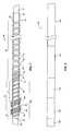
- FIG. 7is a plan view or side elevational view of a partially constructed catheter according to the present invention and shows the inner tube on a mandrel with a platinum ribbon wire wound distally first with a first pitch and then with a second pitch to a first set of four abutting turns, a space on the inner tube and then a second set of four abutting turns, both sets being covered with a film of colloidal tungsten loaded polymer, a 1 st stainless steel ribbon wire helically wound proximally from an intermediate point proximal of a distal end of the inner tube starting over proximal turns of the platinum ribbon wire proximally to a point close to a proximal end of the inner tube and a 2 nd stainless steel ribbon wire, being a continuation of the 1 st stainless steel ribbon wire, wound distally to the intermediate point.
- FIG. 8is plan view or side elevational view of a four segment outer protective polymer sheath which is place over the inner tube and wire reinforcement shown in FIG. 7 .
- a catheter 10comprising a connecting hub 12 , a proximal end 20 , a proximal segment or section or portion 14 , a distal segment, section or portion 16 , and a distal end 18 .
- the completed intravascular catheter 10is designed and constructed to facilitate introduction into a blood vessel and to support further manipulations to reach the target blood vessel.
- Manipulation of the catheter 10is done by the physician, after catheter introduction, external to the blood vessel; that is, the catheter 10 needs to be rotated outside the body, by rotating hub 12 in the proximal segment of the catheter and a corresponding rotational reaction must be achieved in the distal tip 18 inside the body. Therefore, a vascular catheter must transmit torque from the proximal end 20 outside the body to the distal end 18 inside the body.
- FIG. 2An internal design 22 of the intravascular catheter is shown in FIG. 2 .
- the design 22comprises a polymeric inner tube 24 , a distal reinforcing segment 30 , and a proximal reinforcing segment 34 .
- the intravascular catheteris used to diagnose and treat a number of medical conditions of the vascular system using a technique called angiography.
- smaller catheters“micro-catheters”, are used to infuse certain blood clot dissolving drugs to the coronaries or to brain blood vessels in stroke related cases.
- Micro-cathetersare used successfully for deployment of embolic agents and coils in aneurism within the brain, and therefore the catheter is required to advance forward when pushed, be able to be retrieved when pulled and to rotate when torque is applied as part of the maneuvering process to reach the aneurism.
- this micro-catheterincorporates the following internal components: a high temperature extruded polymeric inner tube 24 , a high stiffness reinforcing jacket 34 comprised of 1 st layer 26 and 2 nd layer 28 of helical coiled wire wound over inner tube 24 to form the stiffer proximal reinforcing jacket, and a single layer 28 of helical coiled wire wound over inner tube 24 to form the softer distal reinforcing jacket.
- FIG. 3A close-up view of the distal end of the inner tube 24 is shown in FIG. 3 including lumen 25 , and the end of the reinforcing flat ribbon wire 28 coiled over the inner tube 24 .
- the inner tube 24is made of a high temperature fluorinated polymer having a low coefficient of friction, and a flat ribbon stainless steel or platinum tungsten alloy or palladium alloy wire 28 spiraling-coiled over inner tube 24 to form the distal reinforcing jacket.
- lumen 25becomes the delivery conduit to facilitate deployment of embolic agents or coils to blood vessels in the brain, or infusion of blood clot dissolving drugs to the brain or other areas of the vascular system.
- lumen 25becomes the delivery conduit to facilitate delivery of contrast media to visualize vasculature using a fluoroscope.
- the main components of a “dual segment” catheter designincorporating: the inner tube 24 , the distal reinforcing jacket 28 comprising a single layer of coiled wire, the proximal reinforcing jacket comprising dual layers of coiled wire, inner layer 26 and outer layer 28 , and the protective outer polymeric sheath 36 is illustrated in FIG. 4 .
- the components of the “dual segment” catheter designinclude: the polymeric inner tube 24 , the distal reinforcing jacket comprising a single layer 28 of helical coiled wire, the proximal reinforcing jacket comprised of 1 st layer 26 and 2 nd layer 28 of helical coiled wire, and the outer protective sheath 36 made from low temperature thermoplastic material.
- the main components of a “triple segment” catheter designis shown in FIG. 5 and includes the inner tube 24 , the distal reinforcing jacket 30 comprising a single wire coil 38 made from a material having relatively low stiffness such as platinum or platinum tungsten alloy or palladium alloy, the proximal reinforcing jacket 34 comprising a 1 st layer of coiled wire 50 under a 2 nd layer of coiled wire 48 , both of these layers made of a relatively stiff material such as stainless steel, the intermediate reinforcing jacket comprising a 1 st layer of coiled wire 38 (platinum or platinum tungsten alloy or palladium alloy wire) under a 2 nd layer 50 (stainless steel wire), and the outer protective polymer sheath 36 .
- the inner tube 24includes the inner tube 24 , the distal reinforcing jacket 30 comprising a single wire coil 38 made from a material having relatively low stiffness such as platinum or platinum tungsten alloy or palladium alloy, the proximal reinfor
- the perfluorinated polymeric inner tube 24the distal reinforcing jacket 30 comprising a single wire coil 38 made from a material having relatively low stiffness such as platinum or platinum tungsten alloy or palladium alloy
- the proximal reinforcing jacket 34comprising a 1 st layer of coiled wire 50 under a 2 nd layer of coiled wire 48 , both of these layers being made of a relatively stiff material such as stainless steel
- the intermediate reinforcing jacketcomprising a 1 st layer of helical coiled wire 38 (platinum or platinum tungsten alloy or palladium alloy wire) under a 2 nd layer 50 (stainless steel wire), and the outer protective sheath 36 a catheter 10 is created having unique properties.
- the intermediate reinforcing jacketcomprises a 1 st layer of softer platinum or platinum tungsten alloy or palladium alloy wire 38 and a 2 nd layer of stiffer stainless steel wire 44 , the resulting stiffness is approximately halfway between that of the proximal segment or portion 34 and the distal segment or portion 30 reinforcing jackets, thus providing a moderate transition between the two extremes (the stiff proximal reinforcement and soft distal reinforcement), thereby improving the overall compliance and directional stability of the catheter.
- FIG. 5is illustrated the internal design and construction of a catheter having “Continuously Progressive Compliance” by comprising the perfluorinated polymeric inner tube 24 and a reinforcing jacket 56 comprising one or more spiraling or helical layers of a coiled wire 52 and the outer protective polymer sheath 36 .
- the number of coils per inchis progressively reduced from proximal to distal direction, changing pitch, resulting in a progressively more complaint (less stiff) catheter body from proximal to distal direction.
- the entire reinforcing jacketcan be manufactured with a single wire material, thus resulting in a more cost effective catheter. While the illustrated embodiment shows a stainless steel wire the outer layer can be made of a different material such as platinum if desired.
- Another improvement to the intravascular catheterinvolves the use of a selective pitch and or period (cycle) of the helical winding to render a progressively compliant reinforcement of the catheter body and tip as shown in FIG. 6 .
- the interior reinforcement of one catheter constructed according to the teachings of the present inventionis shown in FIG. 7 and is generally identified with reference numeral 60 .
- the interior reinforcement 60includes an inner tube liner 62 having an inner lumen and being made of PTFE.
- the inner tube 62is shown mounted on a mandrel 64 .
- a proximal segment, section or portion 66 of the inner tube 62 on which a reinforcing jacket is placedcomprises a ribbon wire reinforcement 68 that is wound on the inner tube and that has a length that has a range of approximately 42.3 ⁇ 0.5 to 61.75 ⁇ 0.5 inches.
- the ribbon wire reinforcement 68 on the segment 66is a helically wound stainless steel ribbon wire reinforcement 68 comprising a first ribbon wire layer 70 that starts at a distal end 72 of the proximal portion 66 and extends to a proximal end 76 of the first ribbon wire layer 70 on the proximal portion 66 .
- the stainless steel ribbon wire 68is spirally or helically wound distally in a second outer ribbon wire layer 78 to the distal end 72 of the proximal portion 66 .
- a proximal end segment, section or portion 80 of the inner tube 62is not reinforced and has a length of approximately 2.9 inches.
- a distal portion 82 of the second ribbon wire layer 78is wound over a beginning portion 84 of a platinum/tungsten flat wire 86 which extends forwardly from just before the distal end 72 of the proximal portion 66 distally towards a distal end 87 of a distal segment, section or portion 88 of the inner tube 62 and which defines a second reinforcing jacket.
- the platinum/tungsten flat wire 86can be wound as shown, or can have a change in spacing or variable pitch to a first marker 90 comprising four to nine abutting turns of the platinum/tungsten flat wire 86 , with four turns being shown in FIG. 7 .
- a second layer or second and third layers of the platinum/tungsten flat wiremay be wound over the first nine abutting turns in order to further enhance radiographic registration of the abutting turns or radiopaque markers. Additionally, the radiographic registration can be further enhanced by heat reflow with either indium or tin-lead solder paste placed directly on the abutting turns.
- the pitch of the turns in each layer 70 and 78 of the stainless steel ribbon wire 68is approximately 0.015′′ pitch.
- the pitch of the platinum/tungsten flat wire 86 in a distal portion thereofis approximately 0.010′′ pitch.
- the platinum/tungsten flat wire 86extends forwardly to the first marker 90 and, depending on the type of catheter, the distance of a section A from the distal end 72 of the proximal portion 66 to the center of the first marker 90 is typically about 21.5 ⁇ 0.2 inches, 5.47 ⁇ 0.2 or 2.5 ⁇ 0.2 inches.
- the markers 90 and 92have a width of about 0.025 ⁇ 0.002 inch and may contain one layer or two layers of abutting turns.
- Each of the markers 90 and 92is covered with a thin film layer 94 , 96 of colloidal tungsten loaded polymer which is shown thicker than it actually is in FIG. 7 .
- Each layer 94 , 96is superimposed over marker 90 or 92 to make the marker more radiopaque. It is to be noted that in some embodiments of the micro-catheter, there is only one marker either at the tip or somewhere in the distal segment.
- the distance of a section B from the distal end 72 of the proximal portion 66 to the center of the second marker 92is about 25 ⁇ 0.5 inch, 6.70 ⁇ 0.5, or 3.75 ⁇ 0.5 inch and the distance of a section 93 from the center of the second marker 92 to the distal end 87 of the inner tube 62 is approximately 2.9 inches. This distance may further be titrated in relation to the type of interventional devise that may be deployed from the microcatheter.
- the film layers 94 and 96are typically made of polyether block amide (PEBAX) loaded with colloidal tungsten powder.
- PEBAXpolyether block amide
- An end turn 98 of the platinum/tungsten flat wire 68can be provided as shown located approximately 1.3 ⁇ 0.20 inch from the second marker 92 .
- ribbon wire or flat wireis illustrated in the drawings, the geometry or cross section of the reinforcement wires 68 and can be round or oval as well as flat. Further mono-filar, bifilar, tri-filar or quadra-filar wire reinforcement can be provided.
- a proximal segment of the inner tube 62 including sections 66 and 80comprises 62 to 87 percent of the length of the inner PTFE tube 62 and a distal segment including sections B and 93 comprises 13 to 38 percent of the length of the PTFE inner tube 62 .
- the interior reinforcement 60is covered with a four section polyether block amide (PEBAX) tube 100 shown in FIG. 8 and including a proximal section 102 made of polyether block amide (PEBAX), a proximal intermediate section 104 made of polyether block amide (PEBAX), a distal intermediate section 106 made of polyether block amide (PEBAX) and a short distal end section 108 constructed according to the teachings of U.S. Pat. No. 5,445,624 and made of polyether block amide (PEBAX).
- the four sections of polyether block amide (PEBAX) in tube 100are heat fused over the interior reinforcement 60 of the catheter which in turn bonds to the PTFE inner tube 62 .
- the inner end portion 84 of the platinum/tungsten portion wire 68is secured in place by the outer end portion 82 of the second layer 78 of the helically wound stainless steel wire 68 . Then the cut ends of the wire forming the markers 90 , 92 and the end turn 98 are secured in place by the liners 94 and 96 and by the polyether block amide (PEBAX) tube distal portion 106 .
- PEBAXpolyether block amide
- the outer tube or sheath 100can be extruded over the interior reinforcement 60 .
- the proximal reinforcing wire 68 made of stainless steelhas end portions softened by an annealing process.
- the annealing processcomprises attaching electrodes to a selected desired end portion, passing a substantial electrical current through the electrodes until the wire end portion glows red hot, and then allowing the wire end portion to slowly return to ambient temperature. This process allows the stainless steel wire to conform to the geometry of PTFE inner tube 62 and prevent the end of wire 68 from springing out of the desired geometry.
- the proximal reinforcing jacket 68is made of stainless steel wire 68 which is fed from a spool and the travel speed of the spool holding the stainless steel wire is gradually or periodically increased in order to decrease the number of turns per inch, resulting in a reinforcing jacket having a continuously progressive compliance (softness) from proximal to distal end of the proximal portion of the inner tube 62 .
- an intravascular catheterhaving proximal and distal reinforcing inner jackets, the proximal jacket having superior stiffness and mechanical characteristics than the distal jacket.
- the methodcomprising the steps of:
- a further method according to the present inventionis provided for manufacturing an intravascular catheter inner reinforcement having a proximal section, an intermediate section and a distal section, wherein the proximal section is stiffer than the intermediate section with the intermediate section being softer than proximal section, and the distal section being softer than the intermediate section.
- the methodcomprising the steps of:
- a manufacturing method for annealing or softening the end of a stainless steel helical coiled wire used to form a reinforcing inner jacket in a cathetercomprising the following steps:
- the wire layers in the proximal wire reinforcementcan be made of glass or carbon as well as stainless steel.
Landscapes
- Health & Medical Sciences (AREA)
- Life Sciences & Earth Sciences (AREA)
- Engineering & Computer Science (AREA)
- Biomedical Technology (AREA)
- Pulmonology (AREA)
- Anesthesiology (AREA)
- Biophysics (AREA)
- Heart & Thoracic Surgery (AREA)
- Hematology (AREA)
- Animal Behavior & Ethology (AREA)
- General Health & Medical Sciences (AREA)
- Public Health (AREA)
- Veterinary Medicine (AREA)
- Mechanical Engineering (AREA)
- Media Introduction/Drainage Providing Device (AREA)
Abstract
Description
| U.S. Pat. No. | Patentee |
| 3,485,234 | Stevens |
| 4,044,765 | Kline |
| 4,402,684 | Jessup |
| 4,430,083 | Ganz et al. |
| 4,516,972 | Samson |
| 4,581,390 | Flynn |
| 4,636,346 | Gold et al |
| 4,737,153 | Shimamura et al. |
| 4,842,590 | Tanabe et al. |
| 4,955,862 | Septka |
| 5,156,155 | King |
| 5,234,416 | Macauley et al |
| 5,279,596 | Castaneda et al. |
| 5,308,342 | Sepetka et al |
| 5,382,234 | Cornelius et al |
| 5,445,624 | Jimenez |
| 5,454,795 | Samson |
| 5,458,605 | Klemm |
| 5,554,139 | Okajima |
| 5,695,483 | Samson |
| 5,702,373 | Samson |
| 5,569,200 | Umeno et al |
| 5,782,809 | Umeno et al |
| 5,816,927 | Milo et al. |
| 5,879,342 | Kelly |
| 5,947,940 | Beisel |
| 5,951,539 | Nita et al. |
| 6,152,912 | Jansen et al. |
| 6,824,553 | Samson et al. |
- a) Extruding a polymeric PTFE inner tube having an internal lumen, proximal, intermediate and distal segments, and having proximal and distal ends,
- b) Inserting a mandrel through the internal lumen of the PTFE inner tube, and clamping the mandrel in a bidirectional winding lathe,
- c) Winding two separate layers of reinforcing helical coiled wire or fibers over the proximal outer surface of the PTFE inner tube, the first layer being wound in a proximal direction starting at a point where the proximal and distal segments meet and terminating at the proximal end, at which point the winding is reversed to a distal direction, thus winding a second layer over the first one, and terminating the layer at the same point where the first coiled wire started,
- d) Winding a separate reinforcing helical coiled wire over the distal segment, either by start winding in a distal direction at a point where the proximal and distal segments meet and terminating at the distal end, or by start winding in a proximal direction at the distal end and terminating at the point where the proximal and distal segments meet,
- e) Extruding a polyether block amide polymeric outer sheath over the proximal and distal segments of the PTFE inner tube of the intravascular catheter.
- a) Extruding a perfluorinated polymeric inner tube having an internal lumen,
- b) Inserting a mandrel through the entire lumen of the perfluorinated inner tube, and clamping the mandrel in a bidirectional winding lathe,
- c) Winding a layer of reinforcing stainless steel helical coiled wire around a desired length of the inner tube,
- d) Clamping two electrodes between the desired length of the stainless steel end wire to be annealed,
- e) Clamping a copper heat sink to the catheter side of the stainless steel end wire,
- f) Momentarily applying sufficient AC or DC current between the electrodes until the stainless steel wire turns red hot,
- g) Allowing the stainless steel wire to cool down close to ambient temperature.
- h) Bending or winding the heat treated stainless steel wires to form a radius compliant with the perfluorinated extruded tube.
Claims (4)
Priority Applications (3)
| Application Number | Priority Date | Filing Date | Title |
|---|---|---|---|
| US13/046,687US8366699B2 (en) | 2006-05-12 | 2011-03-11 | Double helix reinforced catheter |
| US13/738,154US8702680B2 (en) | 2006-05-12 | 2013-01-10 | Double helix reinforced catheter |
| US14/221,641US20140207114A1 (en) | 2006-05-12 | 2014-03-21 | Double helix reinforced catheter |
Applications Claiming Priority (2)
| Application Number | Priority Date | Filing Date | Title |
|---|---|---|---|
| US11/433,390US7905877B1 (en) | 2006-05-12 | 2006-05-12 | Double helix reinforced catheter |
| US13/046,687US8366699B2 (en) | 2006-05-12 | 2011-03-11 | Double helix reinforced catheter |
Related Parent Applications (1)
| Application Number | Title | Priority Date | Filing Date |
|---|---|---|---|
| US11/433,390ContinuationUS7905877B1 (en) | 2006-05-12 | 2006-05-12 | Double helix reinforced catheter |
Related Child Applications (1)
| Application Number | Title | Priority Date | Filing Date |
|---|---|---|---|
| US13/738,154ContinuationUS8702680B2 (en) | 2006-05-12 | 2013-01-10 | Double helix reinforced catheter |
Publications (2)
| Publication Number | Publication Date |
|---|---|
| US20110160702A1 US20110160702A1 (en) | 2011-06-30 |
| US8366699B2true US8366699B2 (en) | 2013-02-05 |
Family
ID=43708119
Family Applications (4)
| Application Number | Title | Priority Date | Filing Date |
|---|---|---|---|
| US11/433,390Active2027-11-03US7905877B1 (en) | 2006-05-12 | 2006-05-12 | Double helix reinforced catheter |
| US13/046,687ActiveUS8366699B2 (en) | 2006-05-12 | 2011-03-11 | Double helix reinforced catheter |
| US13/738,154ActiveUS8702680B2 (en) | 2006-05-12 | 2013-01-10 | Double helix reinforced catheter |
| US14/221,641AbandonedUS20140207114A1 (en) | 2006-05-12 | 2014-03-21 | Double helix reinforced catheter |
Family Applications Before (1)
| Application Number | Title | Priority Date | Filing Date |
|---|---|---|---|
| US11/433,390Active2027-11-03US7905877B1 (en) | 2006-05-12 | 2006-05-12 | Double helix reinforced catheter |
Family Applications After (2)
| Application Number | Title | Priority Date | Filing Date |
|---|---|---|---|
| US13/738,154ActiveUS8702680B2 (en) | 2006-05-12 | 2013-01-10 | Double helix reinforced catheter |
| US14/221,641AbandonedUS20140207114A1 (en) | 2006-05-12 | 2014-03-21 | Double helix reinforced catheter |
Country Status (1)
| Country | Link |
|---|---|
| US (4) | US7905877B1 (en) |
Cited By (11)
| Publication number | Priority date | Publication date | Assignee | Title |
|---|---|---|---|---|
| US8986284B2 (en) | 2012-08-07 | 2015-03-24 | Asahi Intecc Co., Ltd. | Catheter |
| US9456913B2 (en) | 2013-03-15 | 2016-10-04 | Cook Medical Technologies Llc | Implant introducer with helical trigger wire |
| US9918705B2 (en) | 2016-07-07 | 2018-03-20 | Brian Giles | Medical devices with distal control |
| US9999749B2 (en) | 2013-01-30 | 2018-06-19 | Asahi Intecc Co., Ltd. | Catheter |
| US10391274B2 (en) | 2016-07-07 | 2019-08-27 | Brian Giles | Medical device with distal torque control |
| US10610666B2 (en) | 2015-12-28 | 2020-04-07 | Covidien Lp | Multi-filament catheter |
| US20210322763A1 (en)* | 2018-07-23 | 2021-10-21 | Advanced Bionics Ag | Reinforced electrode leads and methods for manufacturing the same |
| US11197977B2 (en) | 2017-12-15 | 2021-12-14 | Perfuze Limited | Catheters and devices and systems incorporating such catheters |
| US11400254B2 (en) | 2017-10-27 | 2022-08-02 | Heraeus Medical Components Llc | Microcatheter and method |
| US11446469B2 (en) | 2016-07-13 | 2022-09-20 | Perfuze Limited | High flexibility, kink resistant catheter shaft |
| US12397129B2 (en) | 2015-07-30 | 2025-08-26 | Normedix, Inc. | Coronary guide catheter |
Families Citing this family (115)
| Publication number | Priority date | Publication date | Assignee | Title |
|---|---|---|---|---|
| US7686825B2 (en) | 2004-03-25 | 2010-03-30 | Hauser David L | Vascular filter device |
| US10278682B2 (en)* | 2007-01-30 | 2019-05-07 | Loma Vista Medical, Inc. | Sheaths for medical devices |
| US8858490B2 (en) | 2007-07-18 | 2014-10-14 | Silk Road Medical, Inc. | Systems and methods for treating a carotid artery |
| EP2497520B1 (en) | 2007-07-18 | 2022-04-13 | Silk Road Medical, Inc. | Systems for establishing retrograde carotid arterial blood flow |
| US9687333B2 (en)* | 2007-08-31 | 2017-06-27 | BiO2 Medical, Inc. | Reduced profile central venous access catheter with vena cava filter and method |
| WO2009079545A1 (en)* | 2007-12-19 | 2009-06-25 | Boston Scientific Scimed, Inc. | Structure for use as part of a medical device |
| JP2011510796A (en) | 2008-02-05 | 2011-04-07 | シルク・ロード・メディカル・インコーポレイテッド | Intervention catheter system and method |
| US20100100055A1 (en)* | 2008-05-22 | 2010-04-22 | Td.Jam Medical Technologies , Llc | Devices for Superficial Femoral Artery Intervention |
| US8257420B2 (en)* | 2008-11-14 | 2012-09-04 | Abbott Cardiovascular Systems Inc. | Stent delivery catheter system with high tensile strength |
| WO2010075445A1 (en)* | 2008-12-23 | 2010-07-01 | Silk Road Medical, Inc. | Methods and systems for treatment of acute ischemic stroke |
| US20100204684A1 (en)* | 2009-01-13 | 2010-08-12 | Garrison Michi E | Methods and systems for performing neurointerventional procedures |
| US8591495B2 (en)* | 2011-02-23 | 2013-11-26 | Fischell Innovations, Llc | Introducer sheath with thin-walled shaft |
| US8348925B2 (en)* | 2011-02-23 | 2013-01-08 | Fischell Innovations, Llc | Introducer sheath with thin-walled shaft and improved means for attachment to the skin |
| US8535294B2 (en) | 2011-06-01 | 2013-09-17 | Fischell Innovations Llc | Carotid sheath with flexible distal section |
| US10779855B2 (en) | 2011-08-05 | 2020-09-22 | Route 92 Medical, Inc. | Methods and systems for treatment of acute ischemic stroke |
| EP4101399B1 (en) | 2011-08-05 | 2025-04-09 | Route 92 Medical, Inc. | System for treatment of acute ischemic stroke |
| JP5226906B1 (en)* | 2011-09-12 | 2013-07-03 | オリンパスメディカルシステムズ株式会社 | MEDICAL COIL, MANUFACTURING METHOD THEREOF, AND MEDICAL DEVICE |
| US8747428B2 (en) | 2012-01-12 | 2014-06-10 | Fischell Innovations, Llc | Carotid sheath with entry and tracking rapid exchange dilators and method of use |
| WO2013148652A1 (en)* | 2012-03-27 | 2013-10-03 | Fischell Innovations, Llc | Introducer sheath with thin-walled shaft |
| US10220186B2 (en)* | 2012-05-23 | 2019-03-05 | Becton, Dickinson And Company | Collapse-resistant swellable catheter |
| WO2014047650A1 (en) | 2012-09-24 | 2014-03-27 | Inceptus Medical LLC | Device and method for treating vascular occlusion |
| WO2014049644A1 (en)* | 2012-09-26 | 2014-04-03 | テルモ株式会社 | Corrective jig, image diagnostic device, and image diagnostic device correction method |
| US9504476B2 (en)* | 2012-10-01 | 2016-11-29 | Microvention, Inc. | Catheter markers |
| US9044575B2 (en)* | 2012-10-22 | 2015-06-02 | Medtronic Adrian Luxembourg S.a.r.l. | Catheters with enhanced flexibility and associated devices, systems, and methods |
| EP2916744B1 (en) | 2012-11-09 | 2020-05-20 | St. Jude Medical, Cardiology Division, Inc. | Devices for delivering vascular implants |
| US8784434B2 (en) | 2012-11-20 | 2014-07-22 | Inceptus Medical, Inc. | Methods and apparatus for treating embolism |
| US9192499B2 (en)* | 2013-03-11 | 2015-11-24 | Cook Medical Technologies Llc | Inner catheter for a self-expanding medical device delivery system with a closed coil wire |
| CA2920641C (en) | 2013-08-26 | 2022-08-30 | Merit Medical Systems, Inc. | Sheathless guide, rapid exchange dilator and associated methods |
| US10238406B2 (en) | 2013-10-21 | 2019-03-26 | Inari Medical, Inc. | Methods and apparatus for treating embolism |
| US9265512B2 (en) | 2013-12-23 | 2016-02-23 | Silk Road Medical, Inc. | Transcarotid neurovascular catheter |
| JP5954747B2 (en)* | 2014-03-20 | 2016-07-20 | 朝日インテック株式会社 | catheter |
| US9241699B1 (en) | 2014-09-04 | 2016-01-26 | Silk Road Medical, Inc. | Methods and devices for transcarotid access |
| EP3164086B1 (en)* | 2014-07-01 | 2020-04-08 | Boston Scientific Scimed, Inc. | Overlapped braid termination |
| CN104069582B (en)* | 2014-07-03 | 2017-01-25 | 杭州启明医疗器械有限公司 | Anti-breakage sheathing canal and conveying system with same |
| JP2016016299A (en)* | 2014-07-11 | 2016-02-01 | 朝日インテック株式会社 | Coil body, and medical instrument having coil body |
| US11027104B2 (en) | 2014-09-04 | 2021-06-08 | Silk Road Medical, Inc. | Methods and devices for transcarotid access |
| CN104399175A (en)* | 2014-11-28 | 2015-03-11 | 中山市普利斯微创介入医械有限公司 | Anti-folding guide wire |
| US10426497B2 (en) | 2015-07-24 | 2019-10-01 | Route 92 Medical, Inc. | Anchoring delivery system and methods |
| US11065019B1 (en) | 2015-02-04 | 2021-07-20 | Route 92 Medical, Inc. | Aspiration catheter systems and methods of use |
| CN119949953A (en) | 2015-02-04 | 2025-05-09 | 92号医疗公司 | Intravascular access system, dilator and system including dilator |
| EP3318205B1 (en)* | 2015-07-01 | 2020-01-29 | Olympus Corporation | Treatment instrument for endoscope |
| JP7082052B2 (en) | 2015-09-03 | 2022-06-07 | ネプチューン メディカル インク. | A device for advancing the endoscope in the small intestine |
| US20170072163A1 (en)* | 2015-09-11 | 2017-03-16 | Cathera, Inc. | Catheter shaft and associated devices, systems, and methods |
| US10342571B2 (en) | 2015-10-23 | 2019-07-09 | Inari Medical, Inc. | Intravascular treatment of vascular occlusion and associated devices, systems, and methods |
| CN113796927B (en) | 2015-10-23 | 2025-03-04 | 伊纳里医疗公司 | Intravascular treatment of vascular occlusion and related devices, systems and methods |
| US9700332B2 (en) | 2015-10-23 | 2017-07-11 | Inari Medical, Inc. | Intravascular treatment of vascular occlusion and associated devices, systems, and methods |
| CN115300748A (en)* | 2015-12-18 | 2022-11-08 | 伊纳里医疗有限公司 | Catheter shaft and related devices, systems and methods |
| WO2017147493A1 (en) | 2016-02-24 | 2017-08-31 | Incept, Llc | Enhanced flexibility neurovascular catheter |
| US10118334B2 (en)* | 2016-07-14 | 2018-11-06 | Custom Wire Technologies, Inc. | Wire-reinforced tubing and method of making the same |
| EP3500151A4 (en) | 2016-08-18 | 2020-03-25 | Neptune Medical Inc. | DEVICE AND METHOD FOR IMPROVED VISUALIZATION OF THE SMALL BOWEL |
| US10821268B2 (en)* | 2016-09-14 | 2020-11-03 | Scientia Vascular, Llc | Integrated coil vascular devices |
| FI3528717T3 (en) | 2016-10-24 | 2024-08-09 | Inari Medical Inc | Devices for treating vascular occlusion |
| TW201825137A (en)* | 2016-11-25 | 2018-07-16 | 日商住友電木股份有限公司 | Catheter and process for producing catheter |
| AU2017373953B2 (en) | 2016-12-08 | 2023-05-11 | Abiomed, Inc. | Overmold technique for peel-away introducer design |
| JP7264581B2 (en) | 2017-01-06 | 2023-04-25 | インセプト、リミテッド、ライアビリティ、カンパニー | Antithrombotic coating for aneurysm treatment devices |
| CN110392591B (en) | 2017-01-10 | 2022-06-03 | 92号医疗公司 | Aspiration catheter system and method of use |
| US10864350B2 (en) | 2017-01-20 | 2020-12-15 | Route 92 Medical, Inc. | Single operator intracranial medical device delivery systems and methods of use |
| US10413658B2 (en) | 2017-03-31 | 2019-09-17 | Capillary Biomedical, Inc. | Helical insertion infusion device |
| CN110678219A (en)* | 2017-04-28 | 2020-01-10 | 美国医疗设备有限公司 | Interposer with partially annealed reinforcement element and related systems and methods |
| JP7018501B2 (en)* | 2017-05-23 | 2022-02-10 | ボストン サイエンティフィック サイムド,インコーポレイテッド | Cryoballoon for endovascular catheter system |
| JP7379321B2 (en) | 2017-07-20 | 2023-11-14 | ネプチューン メディカル インク. | Dynamically rigid overtube |
| US11471646B2 (en)* | 2017-08-09 | 2022-10-18 | Accurate Medical Therapeutics Ltd | Microcatheter |
| WO2019050765A1 (en) | 2017-09-06 | 2019-03-14 | Inari Medical, Inc. | Hemostasis valves and methods of use |
| KR102452113B1 (en) | 2017-11-06 | 2022-10-07 | 아비오메드, 인크. | Separable hemostatic valve |
| US11154314B2 (en) | 2018-01-26 | 2021-10-26 | Inari Medical, Inc. | Single insertion delivery system for treating embolism and associated systems and methods |
| US11395665B2 (en) | 2018-05-01 | 2022-07-26 | Incept, Llc | Devices and methods for removing obstructive material, from an intravascular site |
| AU2019262972B2 (en) | 2018-05-01 | 2025-02-27 | Incept, Llc | Devices and methods for removing obstructive material from an intravascular site |
| ES2991910T3 (en) | 2018-05-16 | 2024-12-05 | Abiomed Inc | Removable cover set |
| JP7616642B2 (en) | 2018-05-17 | 2025-01-17 | ルート92メディカル・インコーポレイテッド | Suction catheter system and method of use |
| US12059128B2 (en) | 2018-05-31 | 2024-08-13 | Neptune Medical Inc. | Device and method for enhanced visualization of the small intestine |
| US10953195B2 (en) | 2018-06-01 | 2021-03-23 | Covidien Lp | Flexible tip catheter |
| US11471582B2 (en) | 2018-07-06 | 2022-10-18 | Incept, Llc | Vacuum transfer tool for extendable catheter |
| US11517335B2 (en) | 2018-07-06 | 2022-12-06 | Incept, Llc | Sealed neurovascular extendable catheter |
| CN112714658A (en) | 2018-07-19 | 2021-04-27 | 海王星医疗公司 | Dynamic rigidized composite medical structure |
| CA3114285A1 (en) | 2018-08-13 | 2020-02-20 | Inari Medical, Inc. | System for treating embolism and associated devices and methods |
| EP3877018A4 (en) | 2018-11-08 | 2022-08-10 | Capillary Biomedical, Inc. | LINEAR INTRODUCER WITH ROTARY DRIVE |
| US10512753B1 (en) | 2018-12-07 | 2019-12-24 | John Nguyen | Composite catheter shafts and methods and apparatus for making the same |
| US11766539B2 (en) | 2019-03-29 | 2023-09-26 | Incept, Llc | Enhanced flexibility neurovascular catheter |
| US11793392B2 (en) | 2019-04-17 | 2023-10-24 | Neptune Medical Inc. | External working channels |
| WO2020214221A1 (en) | 2019-04-17 | 2020-10-22 | Neptune Medical Inc. | Dynamically rigidizing composite medical structures |
| CN110269994A (en)* | 2019-06-27 | 2019-09-24 | 深圳市美好创亿医疗科技有限公司 | Conduit and preparation method thereof |
| CN110652645A (en)* | 2019-08-13 | 2020-01-07 | 上海沃比医疗科技有限公司 | Multilayer catheter body and catheter assembly therefor |
| US11134859B2 (en) | 2019-10-15 | 2021-10-05 | Imperative Care, Inc. | Systems and methods for multivariate stroke detection |
| JP7638273B2 (en) | 2019-10-16 | 2025-03-03 | イナリ メディカル, インコーポレイテッド | Systems, devices and methods for treating vascular obstructions |
| CN110947077B (en)* | 2019-12-02 | 2024-05-07 | 心凯诺医疗科技(上海)有限公司 | High-flexibility distal end access guide catheter and preparation method thereof |
| US11638637B2 (en) | 2019-12-18 | 2023-05-02 | Imperative Care, Inc. | Method of removing embolic material with thrombus engagement tool |
| US20230248502A1 (en) | 2019-12-18 | 2023-08-10 | Imperative Care, Inc. | Sterile field clot capture module for use in thrombectomy system |
| US20210316127A1 (en) | 2019-12-18 | 2021-10-14 | Imperative Care, Inc. | Hemostasis valve |
| EP4076611A4 (en) | 2019-12-18 | 2023-11-15 | Imperative Care, Inc. | Methods and systems for treating venous thromboembolic disease |
| CN113747934B (en)* | 2020-03-10 | 2024-07-09 | 因普瑞缇夫护理公司 | Enhanced flexibility neurovascular catheter |
| US11844909B2 (en)* | 2020-03-23 | 2023-12-19 | Boston Scientific Scimed, Inc. | Guide catheter with reinforcing member |
| CA3178444A1 (en)* | 2020-03-30 | 2021-10-07 | Neptune Medical Inc. | Layered walls for rigidizing devices |
| US11992625B2 (en)* | 2020-07-07 | 2024-05-28 | Covidien Lp | Catheter including variable density structural support member |
| US12168102B2 (en) | 2020-07-07 | 2024-12-17 | Covidien Lp | Catheter including surface-treated structural support member |
| US11207497B1 (en) | 2020-08-11 | 2021-12-28 | Imperative Care, Inc. | Catheter with enhanced tensile strength |
| EP4204066A4 (en) | 2020-08-28 | 2024-11-13 | Tandem Diabetes Care, Inc. | INSULIN INFUSION SET |
| US20220062584A1 (en)* | 2020-08-28 | 2022-03-03 | DePuy Synthes Products, Inc. | Ribbon extrusion segments for catheter construction |
| WO2022076893A1 (en) | 2020-10-09 | 2022-04-14 | Route 92 Medical, Inc. | Aspiration catheter systems and methods of use |
| CN114558231B (en)* | 2020-11-27 | 2024-02-20 | 微创神通医疗科技(上海)有限公司 | Conduit transition structure, conduit and choke conduit |
| KR20230133374A (en) | 2021-01-29 | 2023-09-19 | 넵튠 메디컬 인코포레이티드 | Device and method for preventing inadvertent movement of a dynamic stiffening device |
| CN113181517B (en)* | 2021-04-23 | 2022-07-08 | 谱高医疗科技(南京)有限公司 | Micro-catheter with mixed spring winding structure |
| CN113197620B (en)* | 2021-04-30 | 2022-03-11 | 上海璞慧医疗器械有限公司 | Nerve micro-catheter |
| US20230052862A1 (en) | 2021-08-12 | 2023-02-16 | Imperative Care, Inc. | Sterile packaging assembly for robotic interventional device |
| US20230061168A1 (en)* | 2021-08-29 | 2023-03-02 | DePuy Synthes Products, Inc. | Annealing of Discrete Sections of a Reinforcement Layer to Modulate Stiffness of a Catheter |
| USD1077996S1 (en) | 2021-10-18 | 2025-06-03 | Imperative Care, Inc. | Inline fluid filter |
| PL439266A1 (en)* | 2021-10-20 | 2023-04-24 | Extrudan Spółka Z Ograniczoną Odpowiedzialnością | Methods of producing a flexible spiral medical hose and medical hose consisting of a tubular part and a braid |
| EP4463083A1 (en) | 2022-01-11 | 2024-11-20 | Inari Medical, Inc. | Devices for removing clot material from intravascularly implanted devices, and associated systems and methods |
| KR20250003955A (en) | 2022-04-27 | 2025-01-07 | 넵튠 메디컬 인코포레이티드 | Sanitary outer covering for endoscope |
| EP4583954A2 (en)* | 2022-09-09 | 2025-07-16 | Inari Medical, Inc. | Catheters having multiple coil layers, and associated systems and methods |
| WO2024160553A1 (en)* | 2023-02-01 | 2024-08-08 | Vascomed Gmbh | Catheter and system comprising the catheter and an introducer sheath |
| WO2025054176A1 (en)* | 2023-09-08 | 2025-03-13 | Merit Medical Systems, Inc. | Systems and methods of forming a continuous reinforced catheter shaft |
| US20250082899A1 (en)* | 2023-09-08 | 2025-03-13 | Merit Medical Systems, Inc. | Systems and methods of annealing segments of a reinforcing coil of a catheter shaft |
| US12330292B2 (en) | 2023-09-28 | 2025-06-17 | Neptune Medical Inc. | Telescoping robot |
| US12171917B1 (en) | 2024-01-08 | 2024-12-24 | Imperative Care, Inc. | Devices for blood capture and reintroduction during aspiration procedure |
| CN119424856A (en)* | 2024-11-11 | 2025-02-14 | 首都医科大学附属北京天坛医院 | Anti-bending and anti-bite closure tracheal tube and preparation method thereof |
Citations (41)
| Publication number | Priority date | Publication date | Assignee | Title |
|---|---|---|---|---|
| US3346761A (en) | 1965-07-02 | 1967-10-10 | Gen Electric | Incandescent lamp with a tungsten filament with tantalum imbedded in the surface to act as a gettering agent |
| US3485234A (en) | 1966-04-13 | 1969-12-23 | Cordis Corp | Tubular products and method of making same |
| US4044765A (en) | 1975-12-17 | 1977-08-30 | Medical Evaluation Devices And Instruments Corporation | Flexible tube for intra-venous feeding |
| US4402684A (en) | 1981-09-16 | 1983-09-06 | The Kendall Company | Cannula with soft tip |
| US4430083A (en) | 1981-03-06 | 1984-02-07 | American Hospital Supply Corporation | Infusion catheter |
| US4516972A (en) | 1982-01-28 | 1985-05-14 | Advanced Cardiovascular Systems, Inc. | Guiding catheter and method of manufacture |
| US4581390A (en) | 1984-06-29 | 1986-04-08 | Flynn Vincent J | Catheters comprising radiopaque polyurethane-silicone network resin compositions |
| US4636346A (en) | 1984-03-08 | 1987-01-13 | Cordis Corporation | Preparing guiding catheter |
| US4737153A (en) | 1986-02-07 | 1988-04-12 | Kuraray Co., Ltd. | Reinforced therapeutic tube |
| US4842590A (en) | 1983-12-14 | 1989-06-27 | Terumo Kabushiki Kaisha | Catheter and method for making |
| US4955862A (en) | 1989-05-22 | 1990-09-11 | Target Therapeutics, Inc. | Catheter and catheter/guide wire device |
| US5156155A (en) | 1990-07-25 | 1992-10-20 | Hewlett-Packard Company | Transesophageal probe shaft |
| US5234416A (en) | 1991-06-06 | 1993-08-10 | Advanced Cardiovascular Systems, Inc. | Intravascular catheter with a nontraumatic distal tip |
| US5279596A (en) | 1990-07-27 | 1994-01-18 | Cordis Corporation | Intravascular catheter with kink resistant tip |
| US5308342A (en) | 1991-08-07 | 1994-05-03 | Target Therapeutics, Inc. | Variable stiffness catheter |
| US5338296A (en) | 1993-01-06 | 1994-08-16 | Ethicon, Inc. | Catheter and sheath assembly |
| US5382234A (en) | 1993-04-08 | 1995-01-17 | Scimed Life Systems, Inc. | Over-the-wire balloon catheter |
| US5445624A (en) | 1994-01-21 | 1995-08-29 | Exonix Research Corporation | Catheter with progressively compliant tip |
| US5454795A (en) | 1994-06-27 | 1995-10-03 | Target Therapeutics, Inc. | Kink-free spiral-wound catheter |
| US5458605A (en) | 1994-04-04 | 1995-10-17 | Advanced Cardiovascular Systems, Inc. | Coiled reinforced retractable sleeve for stent delivery catheter |
| US5526849A (en)* | 1990-12-12 | 1996-06-18 | Gray; William R. | Flexible duct |
| US5554139A (en) | 1993-12-24 | 1996-09-10 | Terumo Kabushiki Kaisha | Catheter |
| US5569200A (en) | 1994-06-20 | 1996-10-29 | Terumo Kabushiki Kaisha | Vascular catheter |
| US5702373A (en) | 1995-08-31 | 1997-12-30 | Target Therapeutics, Inc. | Composite super-elastic alloy braid reinforced catheter |
| US5816923A (en) | 1993-12-09 | 1998-10-06 | Devices For Vascular Intervention, Inc. | Flexible composite drive shaft for transmitting torque |
| US5879342A (en) | 1996-10-21 | 1999-03-09 | Kelley; Gregory S. | Flexible and reinforced tubing |
| US5947940A (en) | 1997-06-23 | 1999-09-07 | Beisel; Robert F. | Catheter reinforced to prevent luminal collapse and tensile failure thereof |
| US5951539A (en)* | 1997-06-10 | 1999-09-14 | Target Therpeutics, Inc. | Optimized high performance multiple coil spiral-wound vascular catheter |
| US6152912A (en)* | 1997-06-10 | 2000-11-28 | Target Therapeutics, Inc. | Optimized high performance spiral-wound vascular catheter |
| US6165163A (en)* | 1997-09-30 | 2000-12-26 | Target Therapeutics, Inc. | Soft-tip performance braided catheter |
| US6177682B1 (en) | 1998-10-21 | 2001-01-23 | Novacam Tyechnologies Inc. | Inspection of ball grid arrays (BGA) by using shadow images of the solder balls |
| US6210396B1 (en) | 1999-06-24 | 2001-04-03 | Medtronic, Inc. | Guiding catheter with tungsten loaded band |
| US6290692B1 (en)* | 1998-11-03 | 2001-09-18 | Daniel J. Klima | Catheter support structure |
| US6508804B2 (en)* | 1999-07-28 | 2003-01-21 | Scimed Life Systems, Inc. | Catheter having continuous lattice and coil reinforcement |
| US20030191451A1 (en)* | 2002-04-05 | 2003-10-09 | Kevin Gilmartin | Reinforced catheter system |
| US20040002727A1 (en)* | 2002-07-01 | 2004-01-01 | Hwang Jason J. | Coil reinforced catheter inner tubular member |
| US6824553B1 (en)* | 1995-04-28 | 2004-11-30 | Target Therapeutics, Inc. | High performance braided catheter |
| US20050004556A1 (en)* | 2003-06-25 | 2005-01-06 | Pursley Matt D. | Catheter having polymer stiffener rings and method of making the same |
| US7104979B2 (en)* | 1998-06-11 | 2006-09-12 | Target Therapeutics, Inc. | Catheter with composite stiffener |
| US7831311B2 (en)* | 2004-10-21 | 2010-11-09 | Medtronic, Inc. | Reduced axial stiffness implantable medical lead |
| US7850623B2 (en)* | 2005-10-27 | 2010-12-14 | Boston Scientific Scimed, Inc. | Elongate medical device with continuous reinforcement member |
Family Cites Families (11)
| Publication number | Priority date | Publication date | Assignee | Title |
|---|---|---|---|---|
| US4454725A (en) | 1982-09-29 | 1984-06-19 | Carrier Corporation | Method and apparatus for integrating a supplemental heat source with staged compressors in a heat pump |
| US5019057A (en)* | 1989-10-23 | 1991-05-28 | Cordis Corporation | Catheter having reinforcing strands |
| US5176660A (en)* | 1989-10-23 | 1993-01-05 | Cordis Corporation | Catheter having reinforcing strands |
| US6616996B1 (en)* | 1994-10-28 | 2003-09-09 | Medsource Trenton, Inc. | Variable stiffness microtubing and method of manufacture |
| US6508806B1 (en)* | 2000-12-13 | 2003-01-21 | Advanced Cardiovascular Systems, Inc. | Catheter with multi-layer wire reinforced wall construction |
| DE602004016310D1 (en)* | 2003-04-25 | 2008-10-16 | Cook Inc | SUPPLY CATHETER |
| EP1807144A1 (en)* | 2004-09-14 | 2007-07-18 | William, a Cook Australia Pty. Ltd. | Large diameter sheath |
| US20060111649A1 (en)* | 2004-11-19 | 2006-05-25 | Scimed Life Systems, Inc. | Catheter having improved torque response and curve retention |
| US20090240235A1 (en)* | 2004-12-09 | 2009-09-24 | Kaneka Corporation | Medical catheter tube and process for producing the same |
| CN101203265A (en)* | 2005-06-20 | 2008-06-18 | 导管治疗有限公司 | Sleeve steering and reinforcement |
| US9119651B2 (en)* | 2006-02-13 | 2015-09-01 | Retro Vascular, Inc. | Recanalizing occluded vessels using controlled antegrade and retrograde tracking |
- 2006
- 2006-05-12USUS11/433,390patent/US7905877B1/enactiveActive
- 2011
- 2011-03-11USUS13/046,687patent/US8366699B2/enactiveActive
- 2013
- 2013-01-10USUS13/738,154patent/US8702680B2/enactiveActive
- 2014
- 2014-03-21USUS14/221,641patent/US20140207114A1/ennot_activeAbandoned
Patent Citations (43)
| Publication number | Priority date | Publication date | Assignee | Title |
|---|---|---|---|---|
| US3346761A (en) | 1965-07-02 | 1967-10-10 | Gen Electric | Incandescent lamp with a tungsten filament with tantalum imbedded in the surface to act as a gettering agent |
| US3485234A (en) | 1966-04-13 | 1969-12-23 | Cordis Corp | Tubular products and method of making same |
| US4044765A (en) | 1975-12-17 | 1977-08-30 | Medical Evaluation Devices And Instruments Corporation | Flexible tube for intra-venous feeding |
| US4430083A (en) | 1981-03-06 | 1984-02-07 | American Hospital Supply Corporation | Infusion catheter |
| US4402684A (en) | 1981-09-16 | 1983-09-06 | The Kendall Company | Cannula with soft tip |
| US4516972A (en) | 1982-01-28 | 1985-05-14 | Advanced Cardiovascular Systems, Inc. | Guiding catheter and method of manufacture |
| US4842590A (en) | 1983-12-14 | 1989-06-27 | Terumo Kabushiki Kaisha | Catheter and method for making |
| US4636346A (en) | 1984-03-08 | 1987-01-13 | Cordis Corporation | Preparing guiding catheter |
| US4581390A (en) | 1984-06-29 | 1986-04-08 | Flynn Vincent J | Catheters comprising radiopaque polyurethane-silicone network resin compositions |
| US4737153A (en) | 1986-02-07 | 1988-04-12 | Kuraray Co., Ltd. | Reinforced therapeutic tube |
| US4955862A (en) | 1989-05-22 | 1990-09-11 | Target Therapeutics, Inc. | Catheter and catheter/guide wire device |
| US5156155A (en) | 1990-07-25 | 1992-10-20 | Hewlett-Packard Company | Transesophageal probe shaft |
| US5279596A (en) | 1990-07-27 | 1994-01-18 | Cordis Corporation | Intravascular catheter with kink resistant tip |
| US5526849A (en)* | 1990-12-12 | 1996-06-18 | Gray; William R. | Flexible duct |
| US5234416A (en) | 1991-06-06 | 1993-08-10 | Advanced Cardiovascular Systems, Inc. | Intravascular catheter with a nontraumatic distal tip |
| US5308342A (en) | 1991-08-07 | 1994-05-03 | Target Therapeutics, Inc. | Variable stiffness catheter |
| US5338296A (en) | 1993-01-06 | 1994-08-16 | Ethicon, Inc. | Catheter and sheath assembly |
| US5382234A (en) | 1993-04-08 | 1995-01-17 | Scimed Life Systems, Inc. | Over-the-wire balloon catheter |
| US5816923A (en) | 1993-12-09 | 1998-10-06 | Devices For Vascular Intervention, Inc. | Flexible composite drive shaft for transmitting torque |
| US5554139A (en) | 1993-12-24 | 1996-09-10 | Terumo Kabushiki Kaisha | Catheter |
| US5445624A (en) | 1994-01-21 | 1995-08-29 | Exonix Research Corporation | Catheter with progressively compliant tip |
| US5458605A (en) | 1994-04-04 | 1995-10-17 | Advanced Cardiovascular Systems, Inc. | Coiled reinforced retractable sleeve for stent delivery catheter |
| US5569200A (en) | 1994-06-20 | 1996-10-29 | Terumo Kabushiki Kaisha | Vascular catheter |
| US5782809A (en) | 1994-06-20 | 1998-07-21 | Terumo Kabushiki Kaisha | Vascular catheter |
| US5695483A (en)* | 1994-06-27 | 1997-12-09 | Target Therapeutics Inc. | Kink-free spiral-wound catheter |
| US5454795A (en) | 1994-06-27 | 1995-10-03 | Target Therapeutics, Inc. | Kink-free spiral-wound catheter |
| US6824553B1 (en)* | 1995-04-28 | 2004-11-30 | Target Therapeutics, Inc. | High performance braided catheter |
| US5702373A (en) | 1995-08-31 | 1997-12-30 | Target Therapeutics, Inc. | Composite super-elastic alloy braid reinforced catheter |
| US5879342A (en) | 1996-10-21 | 1999-03-09 | Kelley; Gregory S. | Flexible and reinforced tubing |
| US5951539A (en)* | 1997-06-10 | 1999-09-14 | Target Therpeutics, Inc. | Optimized high performance multiple coil spiral-wound vascular catheter |
| US6152912A (en)* | 1997-06-10 | 2000-11-28 | Target Therapeutics, Inc. | Optimized high performance spiral-wound vascular catheter |
| US5947940A (en) | 1997-06-23 | 1999-09-07 | Beisel; Robert F. | Catheter reinforced to prevent luminal collapse and tensile failure thereof |
| US6165163A (en)* | 1997-09-30 | 2000-12-26 | Target Therapeutics, Inc. | Soft-tip performance braided catheter |
| US7104979B2 (en)* | 1998-06-11 | 2006-09-12 | Target Therapeutics, Inc. | Catheter with composite stiffener |
| US6177682B1 (en) | 1998-10-21 | 2001-01-23 | Novacam Tyechnologies Inc. | Inspection of ball grid arrays (BGA) by using shadow images of the solder balls |
| US6290692B1 (en)* | 1998-11-03 | 2001-09-18 | Daniel J. Klima | Catheter support structure |
| US6210396B1 (en) | 1999-06-24 | 2001-04-03 | Medtronic, Inc. | Guiding catheter with tungsten loaded band |
| US6508804B2 (en)* | 1999-07-28 | 2003-01-21 | Scimed Life Systems, Inc. | Catheter having continuous lattice and coil reinforcement |
| US20030191451A1 (en)* | 2002-04-05 | 2003-10-09 | Kevin Gilmartin | Reinforced catheter system |
| US20040002727A1 (en)* | 2002-07-01 | 2004-01-01 | Hwang Jason J. | Coil reinforced catheter inner tubular member |
| US20050004556A1 (en)* | 2003-06-25 | 2005-01-06 | Pursley Matt D. | Catheter having polymer stiffener rings and method of making the same |
| US7831311B2 (en)* | 2004-10-21 | 2010-11-09 | Medtronic, Inc. | Reduced axial stiffness implantable medical lead |
| US7850623B2 (en)* | 2005-10-27 | 2010-12-14 | Boston Scientific Scimed, Inc. | Elongate medical device with continuous reinforcement member |
Cited By (17)
| Publication number | Priority date | Publication date | Assignee | Title |
|---|---|---|---|---|
| US8986284B2 (en) | 2012-08-07 | 2015-03-24 | Asahi Intecc Co., Ltd. | Catheter |
| US9999749B2 (en) | 2013-01-30 | 2018-06-19 | Asahi Intecc Co., Ltd. | Catheter |
| US9456913B2 (en) | 2013-03-15 | 2016-10-04 | Cook Medical Technologies Llc | Implant introducer with helical trigger wire |
| US12397129B2 (en) | 2015-07-30 | 2025-08-26 | Normedix, Inc. | Coronary guide catheter |
| US10610666B2 (en) | 2015-12-28 | 2020-04-07 | Covidien Lp | Multi-filament catheter |
| US10786230B2 (en) | 2016-07-07 | 2020-09-29 | Micronovus, Llc | Medical devices with distal control |
| US11717641B2 (en) | 2016-07-07 | 2023-08-08 | Micronovus, Llc | Medical device with distal torque control |
| US11141141B2 (en) | 2016-07-07 | 2021-10-12 | Micronovus, Llc | Medical devices with distal control |
| US10391274B2 (en) | 2016-07-07 | 2019-08-27 | Brian Giles | Medical device with distal torque control |
| US9918705B2 (en) | 2016-07-07 | 2018-03-20 | Brian Giles | Medical devices with distal control |
| US11446469B2 (en) | 2016-07-13 | 2022-09-20 | Perfuze Limited | High flexibility, kink resistant catheter shaft |
| US11400254B2 (en) | 2017-10-27 | 2022-08-02 | Heraeus Medical Components Llc | Microcatheter and method |
| US11197977B2 (en) | 2017-12-15 | 2021-12-14 | Perfuze Limited | Catheters and devices and systems incorporating such catheters |
| US20210322763A1 (en)* | 2018-07-23 | 2021-10-21 | Advanced Bionics Ag | Reinforced electrode leads and methods for manufacturing the same |
| US20230256239A1 (en)* | 2018-07-23 | 2023-08-17 | Advanced Bionics Ag | Reinforced electrode leads and methods for manufacturing the same |
| US12290679B2 (en)* | 2018-07-23 | 2025-05-06 | Advanced Bionics Ag | Reinforced electrode leads and methods for manufacturing the same |
| US11691003B2 (en)* | 2018-07-23 | 2023-07-04 | Advanced Bionics Ag | Reinforced electrode leads and methods for manufacturing the same |
Also Published As
| Publication number | Publication date |
|---|---|
| US20130131641A1 (en) | 2013-05-23 |
| US8702680B2 (en) | 2014-04-22 |
| US7905877B1 (en) | 2011-03-15 |
| US20110160702A1 (en) | 2011-06-30 |
| US20140207114A1 (en) | 2014-07-24 |
Similar Documents
| Publication | Publication Date | Title |
|---|---|---|
| US8366699B2 (en) | Double helix reinforced catheter | |
| JP3224501B2 (en) | High performance spiral wound catheter | |
| US6152912A (en) | Optimized high performance spiral-wound vascular catheter | |
| US5951539A (en) | Optimized high performance multiple coil spiral-wound vascular catheter | |
| US20220331552A1 (en) | Multi-layer Catheter Construction | |
| US6652508B2 (en) | Intravascular microcatheter having hypotube proximal shaft with transition | |
| EP0930910B1 (en) | Guide catheter with enhanced guidewire tracking | |
| US6143013A (en) | High performance braided catheter | |
| US6165163A (en) | Soft-tip performance braided catheter | |
| US6824553B1 (en) | High performance braided catheter | |
| EP1019130B1 (en) | Peripheral vascular delivery catheter | |
| US5702373A (en) | Composite super-elastic alloy braid reinforced catheter | |
| CN110430913A (en) | Flexible tip conduit | |
| JPH08252316A (en) | Catheter with multilayer section | |
| JPH1071208A (en) | Braided catheter provided with hole on distal side and having torsional resistance | |
| JPH1080490A (en) | Multilayered distal catheter section | |
| US10821264B1 (en) | Mixed coil catheter and process for making same |
Legal Events
| Date | Code | Title | Description |
|---|---|---|---|
| STCF | Information on status: patent grant | Free format text:PATENTED CASE | |
| AS | Assignment | Owner name:CODMAN & SHURTLEFF, INC., MASSACHUSETTS Free format text:ASSIGNMENT OF ASSIGNORS INTEREST;ASSIGNOR:MICRUS ENOVASCULAR LLC;REEL/FRAME:030352/0972 Effective date:20121230 Owner name:DEPUY SPINE, LLC, MASSACHUSETTS Free format text:ASSIGNMENT OF ASSIGNORS INTEREST;ASSIGNOR:CODMAN & SHURTLEFF, INC.;REEL/FRAME:030352/0987 Effective date:20121230 Owner name:DEPUY SYNTHES PRODUCTS, LLC, MASSACHUSETTS Free format text:CHANGE OF NAME;ASSIGNOR:HAND INNOVATIONS LLC;REEL/FRAME:030353/0083 Effective date:20121231 Owner name:HAND INNOVATIONS LLC, FLORIDA Free format text:ASSIGNMENT OF ASSIGNORS INTEREST;ASSIGNOR:DEPUY SPINE, LLC;REEL/FRAME:030353/0075 Effective date:20121230 | |
| AS | Assignment | Owner name:CODMAN & SHURTLEFF, INC., MASSACHUSETTS Free format text:CORRECTIVE ASSIGNMENT TO CORRECT THE REMOVE SERIAL NUMBER 12/554,588 PREVIOUSLY RECORDED ON REEL 030352 FRAME 0973. ASSIGNOR(S) HEREBY CONFIRMS THE ASSIGNMENT;ASSIGNOR:MICRUS ENDOVASCULAR LLC;REEL/FRAME:034535/0733 Effective date:20121230 | |
| FPAY | Fee payment | Year of fee payment:4 | |
| MAFP | Maintenance fee payment | Free format text:PAYMENT OF MAINTENANCE FEE, 8TH YEAR, LARGE ENTITY (ORIGINAL EVENT CODE: M1552); ENTITY STATUS OF PATENT OWNER: LARGE ENTITY Year of fee payment:8 | |
| MAFP | Maintenance fee payment | Free format text:PAYMENT OF MAINTENANCE FEE, 12TH YEAR, LARGE ENTITY (ORIGINAL EVENT CODE: M1553); ENTITY STATUS OF PATENT OWNER: LARGE ENTITY Year of fee payment:12 |