US8366465B2 - Plug apparatus - Google Patents
Plug apparatusDownload PDFInfo
- Publication number
- US8366465B2 US8366465B2US13/213,068US201113213068AUS8366465B2US 8366465 B2US8366465 B2US 8366465B2US 201113213068 AUS201113213068 AUS 201113213068AUS 8366465 B2US8366465 B2US 8366465B2
- Authority
- US
- United States
- Prior art keywords
- plug
- threads
- plugs
- main body
- sleeves
- Prior art date
- Legal status (The legal status is an assumption and is not a legal conclusion. Google has not performed a legal analysis and makes no representation as to the accuracy of the status listed.)
- Expired - Fee Related
Links
Images


Classifications
- H—ELECTRICITY
- H01—ELECTRIC ELEMENTS
- H01R—ELECTRICALLY-CONDUCTIVE CONNECTIONS; STRUCTURAL ASSOCIATIONS OF A PLURALITY OF MUTUALLY-INSULATED ELECTRICAL CONNECTING ELEMENTS; COUPLING DEVICES; CURRENT COLLECTORS
- H01R27/00—Coupling parts adapted for co-operation with two or more dissimilar counterparts
- H—ELECTRICITY
- H01—ELECTRIC ELEMENTS
- H01R—ELECTRICALLY-CONDUCTIVE CONNECTIONS; STRUCTURAL ASSOCIATIONS OF A PLURALITY OF MUTUALLY-INSULATED ELECTRICAL CONNECTING ELEMENTS; COUPLING DEVICES; CURRENT COLLECTORS
- H01R2101/00—One pole
Definitions
- the present disclosurerelates to plug apparatus.
- a typical plug apparatusoften has only one plug tip.
- the plug apparatusis electrically connected to an electronic device by the plug tip being inserted into a socket of the electronic device.
- the plug apparatuscannot be used when the socket of the electronic device is different from the plug tip.
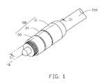
- FIG. 1is a perspective view of a plug apparatus in accordance with an embodiment.
- FIG. 2is a disassembled perspective view of the plug apparatus of FIG. 1 .
- FIG. 3is a cross-sectional view taken along line III-III of FIG. 1 .
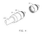
- FIG. 4is a partially assembled perspective view of FIG. 2 .
- FIG. 1a perspective view of a plug apparatus 100 in accordance with an embodiment is shown.
- the plug apparatus 100is electrically connected to a peripheral device (such as an earphone) via a cable 200 .
- the plug apparatus 100can be inserted into a socket of an electronic device (not shown), such that the peripheral device is electrically connected to the electronic device.
- the plug apparatus 100includes a main body 10 and a plurality of plugs successively secured to the main body 10 .
- the plurality of plugshave various plug tips for being inserted into corresponding types of sockets.
- a first plug 20 and a second plug 30are described for explaining the structure of the plug apparatus 100 .
- the main body 10is a substantially hollow cylinder and has an axis A.
- the main body 10is electrically connected to the cable 200 .
- the main body 10includes a fixing portion 110 and a connecting portion 120 into which the fixing portion 110 may be threaded.
- the fixing portion 110is electrically connected to an end of the cable 200 .
- the fixing portion 110defines a receiving hole 112 .
- the receiving hole 112extends in a direction parallel to the axis A, and is used for receiving an end of the cable 200 .
- the outer surface of the fixing portion 110(first threads 114 ) is threaded.
- the connecting portion 120defines a first thread hole 122 including a plurality of internal second threads 124 .
- the first thread hole 122extends longitudinally, and is adapted to receive the fixing portion 110 .
- the diameter of the first thread hole 122is substantially equal to that of the fixing portion 110 .
- the second threads 124match with the first threads 114 .
- the outer surface of the connecting portion 120defines a plurality of third threads 126 .
- the third threads 126are arranged adjacent to an end of the connecting portion 120 opposite to the cable 200 .
- the first plug 20is electrically connected to and coaxial with the main body 10 .
- the first plug 20includes a cylindrical portion 210 and a first plug tip 220 arranged at an end of the cylindrical portion 210 .
- the cylindrical portion 210 and the first plug tip 220are coaxial.
- An end of the cylindrical portion 210 opposite to the first plug tip 220longitudinally recesses to define a second thread hole 212 .
- the second thread hole 212includes a plurality of internal fourth threads 214 .
- the fourth threads 214engage with the third threads 126 .
- the first plug 20sleeves on the main body 10 by the third threads 126 threadedly engaging with the fourth threads 214 .
- the end portion of the second thread hole 212further recesses longitudinally to define a first receiving portion 218 .
- the outer surface of the cylindrical portion 210further defines a plurality of fifth threads 216 .
- the fifth threads 216are arranged adjacent to an end of the cylindrical portion 210 adjacent to the first plug top 220 .
- the second plug 30is capable of sleeving on and detaching from the first plug 20 .
- the structure of the second plug 30is substantially similar to the structure of the first plug 20 .
- the second plug 30has a second plug tip 310 .
- the second plug tip 310is also of a recognized standard which is different from the first plug tip 220 , and the first plug tip 220 and the second plug tip 310 match with different types of sockets, such that the plug apparatus 100 may connect to different electronic devices by means of the first plug 20 and the second plug 30 .
- the second plug 30defines a third thread hole 312 including a plurality of internal sixth threads 314 .
- the sixth threads 314threadedly engage with the fifth threads 216 , such that the second plug 30 sleeves on the first plug 20 .
- the end portion of the third thread hole 312recesses longitudinally to define a second receiving portion 320 .
- the size of the second receiving portion 320is substantially equal to that of the first receiving portion 218 .
- the second receiving portion 320is used for receiving the first plug tip 220 when the second plug 30 sleeves on the first plug 20 .
- the outer surface of the second plug 30defines a plurality of seventh threads 316 .
- the seventh threads 316are arranged adjacent to the second plug tip 310 .
- the sixth threads 314can also threadedly engage with the third threads 126 , and the seventh threads 316 threadedly engage with the fourth threads 214 .
- the second plug 30can sleeve on the main body 10 directly, and the first plug 20 can sleeve on the second plug 30 with the second plug tip 210 being received in the first receiving portion 218 .
- the other plugs (hereinafter described as third plugs and are not shown) of the plug apparatus 100have various plug tip standards different from both the first plug tip 220 and the second plug tip 310 , such that the plug apparatus 100 further matches with more various types of sockets.
- the structure of each third plugis similar to that of the first and second plugs 20 , 30 . These plugs successively sleeve on the second plug 30 by threadedly engaging with the seventh threads 316 .
- the cable 200is secured to the fixing portion 110 , the fixing portion 110 is then threaded into the first thread hole 122 ; Secondly, the first plug 20 sleeves on the main body 10 by the third threads 126 threadedly engaging with the fourth threads 214 . Finally, the second plug 30 sleeves on the first plug 20 by the sixth threads 314 threadedly engaging with the fifth threads 216 . Furthermore, the third plugs successively sleeve on the second plug 30 in a manner which is similar to that of the second plug 30 sleeving to the first plug 20 .
- the plug apparatus 100is capable of matching with various sockets.
Landscapes
- Details Of Connecting Devices For Male And Female Coupling (AREA)
- Coupling Device And Connection With Printed Circuit (AREA)
Abstract
Description
Claims (14)
Applications Claiming Priority (3)
| Application Number | Priority Date | Filing Date | Title |
|---|---|---|---|
| CN201010616907.2 | 2010-12-31 | ||
| CN201010616907 | 2010-12-31 | ||
| CN201010616907.2ACN102544945B (en) | 2010-12-31 | 2010-12-31 | Plug-assembly |
Publications (2)
| Publication Number | Publication Date |
|---|---|
| US20120171880A1 US20120171880A1 (en) | 2012-07-05 |
| US8366465B2true US8366465B2 (en) | 2013-02-05 |
Family
ID=46351198
Family Applications (1)
| Application Number | Title | Priority Date | Filing Date |
|---|---|---|---|
| US13/213,068Expired - Fee RelatedUS8366465B2 (en) | 2010-12-31 | 2011-08-18 | Plug apparatus |
Country Status (2)
| Country | Link |
|---|---|
| US (1) | US8366465B2 (en) |
| CN (1) | CN102544945B (en) |
Cited By (3)
| Publication number | Priority date | Publication date | Assignee | Title |
|---|---|---|---|---|
| US20120068535A1 (en)* | 2010-09-20 | 2012-03-22 | Radioshack Corporation | Energy converter, and associated method, for providing converted energy to a set of electronic devices |
| US8911246B2 (en)* | 2012-02-23 | 2014-12-16 | Jeffrey D. Carnevali | Universal adaptor mount for a docking station |
| US8926349B2 (en)* | 2012-02-23 | 2015-01-06 | Jeffrey D. Carnevali | Universal adaptor mount for a docking station |
Families Citing this family (2)
| Publication number | Priority date | Publication date | Assignee | Title |
|---|---|---|---|---|
| CN102983470B (en)* | 2012-12-03 | 2015-05-13 | 华为终端有限公司 | Connector and electronic equipment with same |
| CN113904171A (en)* | 2021-10-15 | 2022-01-07 | 国网河北省电力有限公司魏县供电分公司 | Portable cable connecting terminal |
Citations (12)
| Publication number | Priority date | Publication date | Assignee | Title |
|---|---|---|---|---|
| US4367001A (en)* | 1979-10-05 | 1983-01-04 | Sony Corporation | Multifunction concentric plug |
| US4803728A (en)* | 1987-06-23 | 1989-02-07 | Lueken Jeffrey A | Stereo mixing jack |
| US4944686A (en)* | 1989-05-01 | 1990-07-31 | Audio Authority Corporation | Solderless electrical connector |
| US5419707A (en)* | 1993-12-17 | 1995-05-30 | Kelley; Shawn T. | Swivel electrical connector |
| US5658158A (en)* | 1995-08-28 | 1997-08-19 | Milan; Henry | Modular surge protection system with interchangeable surge protection modules |
| US5791919A (en)* | 1996-04-30 | 1998-08-11 | Constant Velocity Transmission Lines, Inc. | Universal connector |
| US5885109A (en)* | 1997-10-16 | 1999-03-23 | Lee; Chiu-Shan | Electrical adapters |
| US6406313B1 (en)* | 2001-01-04 | 2002-06-18 | Monster Cable Products, Inc. | Interchangeable connector system |
| US6600826B1 (en)* | 2001-07-06 | 2003-07-29 | Elius A. Xavier | Modularly expandible, multi-user audio headphone |
| US6981895B2 (en)* | 1999-08-23 | 2006-01-03 | Patrick Potega | Interface apparatus for selectively connecting electrical devices |
| US7121872B1 (en)* | 2005-05-31 | 2006-10-17 | Centerpin Technology Inc. | Electrical connector with interference collar |
| US7144273B1 (en)* | 2005-09-19 | 2006-12-05 | John Mezzalingua Associates, Inc. | Insulated cable attachment device |
- 2010
- 2010-12-31CNCN201010616907.2Apatent/CN102544945B/ennot_activeExpired - Fee Related
- 2011
- 2011-08-18USUS13/213,068patent/US8366465B2/ennot_activeExpired - Fee Related
Patent Citations (12)
| Publication number | Priority date | Publication date | Assignee | Title |
|---|---|---|---|---|
| US4367001A (en)* | 1979-10-05 | 1983-01-04 | Sony Corporation | Multifunction concentric plug |
| US4803728A (en)* | 1987-06-23 | 1989-02-07 | Lueken Jeffrey A | Stereo mixing jack |
| US4944686A (en)* | 1989-05-01 | 1990-07-31 | Audio Authority Corporation | Solderless electrical connector |
| US5419707A (en)* | 1993-12-17 | 1995-05-30 | Kelley; Shawn T. | Swivel electrical connector |
| US5658158A (en)* | 1995-08-28 | 1997-08-19 | Milan; Henry | Modular surge protection system with interchangeable surge protection modules |
| US5791919A (en)* | 1996-04-30 | 1998-08-11 | Constant Velocity Transmission Lines, Inc. | Universal connector |
| US5885109A (en)* | 1997-10-16 | 1999-03-23 | Lee; Chiu-Shan | Electrical adapters |
| US6981895B2 (en)* | 1999-08-23 | 2006-01-03 | Patrick Potega | Interface apparatus for selectively connecting electrical devices |
| US6406313B1 (en)* | 2001-01-04 | 2002-06-18 | Monster Cable Products, Inc. | Interchangeable connector system |
| US6600826B1 (en)* | 2001-07-06 | 2003-07-29 | Elius A. Xavier | Modularly expandible, multi-user audio headphone |
| US7121872B1 (en)* | 2005-05-31 | 2006-10-17 | Centerpin Technology Inc. | Electrical connector with interference collar |
| US7144273B1 (en)* | 2005-09-19 | 2006-12-05 | John Mezzalingua Associates, Inc. | Insulated cable attachment device |
Cited By (3)
| Publication number | Priority date | Publication date | Assignee | Title |
|---|---|---|---|---|
| US20120068535A1 (en)* | 2010-09-20 | 2012-03-22 | Radioshack Corporation | Energy converter, and associated method, for providing converted energy to a set of electronic devices |
| US8911246B2 (en)* | 2012-02-23 | 2014-12-16 | Jeffrey D. Carnevali | Universal adaptor mount for a docking station |
| US8926349B2 (en)* | 2012-02-23 | 2015-01-06 | Jeffrey D. Carnevali | Universal adaptor mount for a docking station |
Also Published As
| Publication number | Publication date |
|---|---|
| US20120171880A1 (en) | 2012-07-05 |
| CN102544945B (en) | 2016-05-18 |
| CN102544945A (en) | 2012-07-04 |
Similar Documents
| Publication | Publication Date | Title |
|---|---|---|
| US7491081B2 (en) | Electrical connector having plug and socket components | |
| US8366465B2 (en) | Plug apparatus | |
| US8348697B2 (en) | Coaxial cable connector having slotted post member | |
| US9723873B2 (en) | Electronic cigarette | |
| BRPI0604292A (en) | electrical connector for solid external conductor coaxial cable, connector in combination with coaxial cable, method for manufacturing electrical connector for solid external conductor coaxial cable | |
| US20080064259A1 (en) | Step up pin for coax cable connector | |
| CN106795902B (en) | Hole Filling Sleeve and Washer Design for Bolt Placement | |
| WO2006104617A3 (en) | Compression connector for coaxial cable | |
| CN104347969B (en) | Conductor connector for power cable | |
| WO2009001520A1 (en) | Polymer bushing insulator and cable terminating connection part using the polymer bushing insulator | |
| US8926362B2 (en) | Power adaptor | |
| KR102123717B1 (en) | a connector for a coaxial cable | |
| CN104917012B (en) | Test connector of radio frequency coaxial cable splitter | |
| US8123556B2 (en) | Low profile compact RF coaxial to planar transmission line interface | |
| US8784138B2 (en) | Connector assembly | |
| CN202487889U (en) | Threaded-connection electric connector | |
| BR102012020381B8 (en) | Connector for an electrical cable and method for attaching connector | |
| CN200976400Y (en) | Electrical connector | |
| CN105703145A (en) | Detachably hermetically-sealed connector | |
| CN204179367U (en) | Anti-loose wire harness fixed cover | |
| CN202384570U (en) | Quick plugging connector matched with N-type radio-frequency coaxial connector port | |
| US20130137311A1 (en) | Connector assembly | |
| MX2021002893A (en) | Modular conductor connector assemblies and connecting methods. | |
| CN206806888U (en) | Cable fixing piece | |
| CN210576864U (en) | Screwless fixed socket capable of climbing wall |
Legal Events
| Date | Code | Title | Description |
|---|---|---|---|
| AS | Assignment | Owner name:FU TAI HUA INDUSTRY (SHENZHEN) CO., LTD., CHINA Free format text:ASSIGNMENT OF ASSIGNORS INTEREST;ASSIGNOR:CHENG, QUAN-CHANG;REEL/FRAME:026775/0164 Effective date:20110727 Owner name:HON HAI PRECISION INDUSTRY CO., LTD., TAIWAN Free format text:ASSIGNMENT OF ASSIGNORS INTEREST;ASSIGNOR:CHENG, QUAN-CHANG;REEL/FRAME:026775/0164 Effective date:20110727 | |
| STCF | Information on status: patent grant | Free format text:PATENTED CASE | |
| FPAY | Fee payment | Year of fee payment:4 | |
| MAFP | Maintenance fee payment | Free format text:PAYMENT OF MAINTENANCE FEE, 8TH YEAR, LARGE ENTITY (ORIGINAL EVENT CODE: M1552); ENTITY STATUS OF PATENT OWNER: LARGE ENTITY Year of fee payment:8 | |
| FEPP | Fee payment procedure | Free format text:MAINTENANCE FEE REMINDER MAILED (ORIGINAL EVENT CODE: REM.); ENTITY STATUS OF PATENT OWNER: LARGE ENTITY | |
| LAPS | Lapse for failure to pay maintenance fees | Free format text:PATENT EXPIRED FOR FAILURE TO PAY MAINTENANCE FEES (ORIGINAL EVENT CODE: EXP.); ENTITY STATUS OF PATENT OWNER: LARGE ENTITY | |
| STCH | Information on status: patent discontinuation | Free format text:PATENT EXPIRED DUE TO NONPAYMENT OF MAINTENANCE FEES UNDER 37 CFR 1.362 | |
| FP | Lapsed due to failure to pay maintenance fee | Effective date:20250205 |