US8366155B1 - Coupler - Google Patents
CouplerDownload PDFInfo
- Publication number
- US8366155B1 US8366155B1US12/779,170US77917010AUS8366155B1US 8366155 B1US8366155 B1US 8366155B1US 77917010 AUS77917010 AUS 77917010AUS 8366155 B1US8366155 B1US 8366155B1
- Authority
- US
- United States
- Prior art keywords
- center section
- coupler
- tab
- cap ring
- flange
- Prior art date
- Legal status (The legal status is an assumption and is not a legal conclusion. Google has not performed a legal analysis and makes no representation as to the accuracy of the status listed.)
- Expired - Fee Related, expires
Links
- 238000007789sealingMethods0.000claimsabstract2
- 230000007423decreaseEffects0.000description2
- 239000002131composite materialSubstances0.000description1
- 238000004590computer programMethods0.000description1
- 238000010586diagramMethods0.000description1
- 230000000694effectsEffects0.000description1
- 239000012530fluidSubstances0.000description1
- 239000000463materialSubstances0.000description1
- 238000012986modificationMethods0.000description1
- 230000004048modificationEffects0.000description1
- 238000006467substitution reactionMethods0.000description1
Images


Classifications
- F—MECHANICAL ENGINEERING; LIGHTING; HEATING; WEAPONS; BLASTING
- F16—ENGINEERING ELEMENTS AND UNITS; GENERAL MEASURES FOR PRODUCING AND MAINTAINING EFFECTIVE FUNCTIONING OF MACHINES OR INSTALLATIONS; THERMAL INSULATION IN GENERAL
- F16L—PIPES; JOINTS OR FITTINGS FOR PIPES; SUPPORTS FOR PIPES, CABLES OR PROTECTIVE TUBING; MEANS FOR THERMAL INSULATION IN GENERAL
- F16L55/00—Devices or appurtenances for use in, or in connection with, pipes or pipe systems
- F16L55/16—Devices for covering leaks in pipes or hoses, e.g. hose-menders
- F16L55/168—Devices for covering leaks in pipes or hoses, e.g. hose-menders from outside the pipe
- F16L55/178—Devices for covering leaks in pipes or hoses, e.g. hose-menders from outside the pipe by clamping an outer gasket against a joint with sleeve or socket
- F—MECHANICAL ENGINEERING; LIGHTING; HEATING; WEAPONS; BLASTING
- F16—ENGINEERING ELEMENTS AND UNITS; GENERAL MEASURES FOR PRODUCING AND MAINTAINING EFFECTIVE FUNCTIONING OF MACHINES OR INSTALLATIONS; THERMAL INSULATION IN GENERAL
- F16L—PIPES; JOINTS OR FITTINGS FOR PIPES; SUPPORTS FOR PIPES, CABLES OR PROTECTIVE TUBING; MEANS FOR THERMAL INSULATION IN GENERAL
- F16L55/00—Devices or appurtenances for use in, or in connection with, pipes or pipe systems
- F16L55/16—Devices for covering leaks in pipes or hoses, e.g. hose-menders
- F16L55/168—Devices for covering leaks in pipes or hoses, e.g. hose-menders from outside the pipe
- F16L55/17—Devices for covering leaks in pipes or hoses, e.g. hose-menders from outside the pipe by means of rings, bands or sleeves pressed against the outside surface of the pipe or hose
- F16L55/1715—Devices for covering leaks in pipes or hoses, e.g. hose-menders from outside the pipe by means of rings, bands or sleeves pressed against the outside surface of the pipe or hose the ring or the sleeve being tightened by hooks, pawls, or other movable members
Definitions
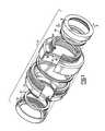
- FIG. 1is an exploded, perspective of a disassembled coupler according to one embodiment of the present invention
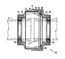
- FIG. 2is an exploded cross-sectional view of a disassembled coupler according to one embodiment of the present invention
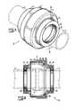
- FIG. 3is a perspective view of an assembled coupler according to one embodiment of the present invention.
- FIG. 4is a cross-sectional view of an assembled coupler according to one embodiment of the present invention.
- FIG. 5is a cross-sectional detail of an assembled coupler according to one embodiment of the present invention.
- FIG. 6is an illustrative diagram showing a parallel, lateral offset pipe joint and the reduced angular misalignment between the pipes and the coupler achieved when the seals engaging the offset pipes are spaced from the offset joint, as in the present invention
- FIG. 7is a cross-sectional view of a coupler according to one embodiment of the present invention installed on an angularly offset pipe joint;
- FIG. 8is a cross-sectional view of a coupler according to one embodiment of the present invention installed on a longitudinally offset pipe joint;
- FIG. 9is a detail view of a locking mechanism according to one embodiment of the present invention.
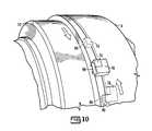
- FIG. 10is a detail view of a locking mechanism according to another embodiment of the present invention.
- FIG. 11is a detail view of a locking mechanism according to another embodiment of the present invention.
- FIGS. 12A and 12Bshow perspective and cross-sectional views, respectively, of a gasket having a round cross-section.
- FIGS. 13A and 13Bshow perspective and cross-sectional views, respectively, of a gasket having an X-shaped cross-section.
- the coupler 10 of the present inventioncan be used as a redundant coupler or primary coupler; the term “redundant” here meaning that the coupler 10 of the present invention can be installed over an existing primary coupler (see FIG. 4 ). It is suitable for use with all types of fluids and in positive or negative pressure environments.
- the coupler 10 of the present inventionis generally comprised of four rigid components 12 , 14 , 16 , and 18 and three gasket rings 20 , 22 , and 24 .
- the rigid componentsinclude a first center section 12 , a second center section 14 , a first cap ring 16 and a second cap ring 18 .
- first and secondthe “first” will typically be to the left of the “second.”
- the two exceptions to this conventionbeing the three gasket rings and three abutments, as explained below.
- the component in the middle positionis referred to as the “first.”
- These rigid componentsare typically cylindrical.
- cylindricalis used to refer to the general shape of the component and does not mean that the component (1) does not vary in size from one end to the other (e.g. is not stepped or belled), and (2) does not have other surface features, including but not limited to threads, abutments, tabs, and flanges.
- First center section 12has a first end 26 and a second end 28 .
- Second center section 14has a first end 30 and a second end 32 .
- First cap ring 16has a first end 40 and a second end 42 .
- Second cap ring 18has a first end 44 and a second end 46 . Abutting ends of these components are designed to engage one another. Accordingly, the second end 28 of the first center section 12 is dimensioned to engage the first end 30 of second center section 14 .
- the second end 42 of first cap ring 16is dimensioned to engage the first end 26 of first center section 12 and the first end 44 of second cap ring 18 is dimensioned to engage the second end 32 of the second center section 14 .
- a gasket ringis positioned between the center sections 12 and 14 and also between each cap ring 16 and 18 and the center the cap ring engages.
- first gasket ring 20resides between first center section 12 and second center section 14
- second gasket ring 22resides between first cap ring 16 and first center section 12
- third gasket ring 24resides between second center section 14 and second cap ring 18 .
- the gasket rings 20 , 22 , and 24allow for a seal to be created between the components.
- the second and third gasket rings 22 and 24in addition to creating a seal between the cap rings 16 and 18 and the center section 12 and 14 , also create a seal around the pipes 2 and 4 ( FIG. 3 ).
- the particular embodiment of the present invention 10 shown in FIG. 2has threads to allow the rigid components to engage one another. Specifically, the outer surfaces 48 and 52 of first and second ends 26 and 28 of first center section 12 are threaded. Likewise, the inside surface 56 of the first end 30 and the outside surface 58 of the second end 32 of the second center section 14 are threaded. Finally, the inside surfaces 64 and 66 of cap rings 16 and 18 , respectively, are threaded.
- the present inventionis not limited to using threads to make the rigid components engagable. Any means known in the art could be used to combine the components and this disclosure and the claims appended hereto should be read to include all means known in the art.
- this particular embodiment of the present inventionhas flanges 36 , 50 , 60 , 62 , and 68 and groove 38 to engage gasket rings 20 , 22 , and 24 .
- first gasket ring 20is received between flange 36 in first center section 12 and groove 38 in second center section 14 .
- second gasket ring 22is received between flange 62 and flange 50 and third gasket ring 24 is received between flange 60 and flange 68 .
- references to, for example, “the flanged inner surface 62 of first cap ring 16 ” and “the flange 62 on the inner surface of first cap ring 16 ”mean the same thing—the term “flanged” simply meaning that there is a flange thereon.
- the second end 28 of first center section 12 and the first end 30 of second center section 14are larger in diameter than the first end 26 of first center section 12 and second end 32 of second center section 14 .
- This featurecreates a volume of space 34 ( FIGS. 4 and 5 ) inside the coupler 10 sufficient to allow the coupler 10 of the present invention to be used over a separate primary coupler 6 ( FIG. 4 ).
- this volume of spacecontributes to this coupler's ability to maintain its seal around the joint even when the joint is offset. Because this coupler does not bear directly on the joint itself (i.e.
- the jointis offset, it has little effect on the coupler.
- the volume of space 34 inside the coupler 10allows the coupler 10 to accommodate an offset joint without losing its seal around the joint.
- the manner in which the joint is offsetis immaterial.
- FIG. 3shows a perspective view of a coupler 10 according to one embodiment of the present invention installed upon the joint between pipes 2 and 4 .
- this particular embodiment of coupler 10has abutments 70 , 72 , and 74 , which prevent the over tightening of the components and resulting deformation of the gasket rings.
- abutment 70prevents second center section 14 from being over tightened onto first center section 12 , thereby preventing gasket ring 20 from being deformed.
- abutment 72prevents first cap ring 16 from being over tightened onto first center section 12 , thereby preventing gasket ring 22 from being deformed.
- abutment 74prevents second cap ring 18 from being over tightened onto second center section 14 , thereby preventing third gasket ring 24 from being deformed.
- gasket rings 20 , 22 , and 24although the gasket rings in the figures have a square cross-section, the present invention can utilize gasket rings of a variety of configurations.
- one or more of the gasket ringscan have a rectangular cross section, a circular or oval cross section ( FIGS. 12A and 12B ), an X-shaped cross section ( FIGS. 13A and 13B ), or a C-shaped cross section.
- Gasket rings having any configuration known in the artcan be utilized with the coupler 10 of the present invention.
- the gasket ringscan be made of any single material known in the art as well as any composite material known in the art.
- second and third gasket rings 22 and 24are spaced apart from the joint between pipes 2 and 4 . This feature permits the coupler of the present invention to maintain its seal around the pipe joint even when the pipes are offset.
- FIG. 6an illustrative figure that does not show the coupler of the prior art but is intended to show the advantage of spacing longitudinally the second and third gasket rings 22 and 24 (i.e. apart from one another and from the ends of pipes 2 and 4 ).
- the pipe joint in FIG. 6is laterally offset. That is, the centerlines of pipes 2 and 4 , while parallel, are not coincident. When this occurs, any coupler that is used to seal the joint will span from the first pipe to the second pipe and will be at an oblique angle (slightly out of parallel) with respect to both pipes.
- FIG. 6an illustrative figure that does not show the coupler of the prior art but is intended to show the advantage of spacing longitudinally the second and third gasket rings 22 and 24 (i.e. apart from one another and from the ends of pipes 2 and 4 ).
- the coupler of the present inventionis more likely to maintain its seal around the joint between offset pipes than a coupler that contacts the pipes closer to the joint.
- This featurecontributes to the ability of the coupler 10 of the present invention to maintain its seal around joints, even when they are offset laterally ( FIG. 6 ), angularly ( FIG. 7 ), or longitudinally ( FIG. 8 ), or any combination of these modes.
- FIG. 9another feature of the present invention is that the rigid components 12 , 14 , 16 , and 18 can be locked together. Locking the components prevents the coupler 10 from losing its seal around the pipe joint, even when the coupler 10 is subjected to vibration and/or substantial temperature swings.
- the specific embodiment of the present invention 10 shown in FIG. 9has a locking mechanism comprised of a first tab 76 on first center section 12 and a second tab 78 on second center section 14 .
- Tabs 76 and 78have posts 84 and 86 , respectively, extending therefrom.
- a C-shaped clip 80 with holes 88can be clipped onto the posts 84 and 86 and around tabs 76 and 78 .
- FIG. 10shows a similar locking mechanism that utilizes a latch 90 instead of a C-shaped clip.
- Latch 90can be spring-loaded.
- FIG. 11shows a third embodiment of the locking mechanism wherein tabs 76 and 78 and buckle 92 are used to ensure that first center section 12 and second center section 14 remain fully engaged.
- the means for locking of the present inventionencompass all of these structural variations as well as any other latch or buckle known in the art that could be used to lock the two center sections 12 and 14 to one another or to cap rings 16 and 18 .
Landscapes
- Engineering & Computer Science (AREA)
- General Engineering & Computer Science (AREA)
- Mechanical Engineering (AREA)
- Joints With Pressure Members (AREA)
Abstract
Description
Claims (4)
Priority Applications (1)
| Application Number | Priority Date | Filing Date | Title |
|---|---|---|---|
| US12/779,170US8366155B1 (en) | 2010-05-13 | 2010-05-13 | Coupler |
Applications Claiming Priority (1)
| Application Number | Priority Date | Filing Date | Title |
|---|---|---|---|
| US12/779,170US8366155B1 (en) | 2010-05-13 | 2010-05-13 | Coupler |
Publications (1)
| Publication Number | Publication Date |
|---|---|
| US8366155B1true US8366155B1 (en) | 2013-02-05 |
Family
ID=47604509
Family Applications (1)
| Application Number | Title | Priority Date | Filing Date |
|---|---|---|---|
| US12/779,170Expired - Fee RelatedUS8366155B1 (en) | 2010-05-13 | 2010-05-13 | Coupler |
Country Status (1)
| Country | Link |
|---|---|
| US (1) | US8366155B1 (en) |
Cited By (4)
| Publication number | Priority date | Publication date | Assignee | Title |
|---|---|---|---|---|
| US20170152975A1 (en)* | 2015-11-30 | 2017-06-01 | Yi-Chuan Huang | Rotatable connector for connecting a fluid transmission pipe |
| USD832860S1 (en)* | 2015-01-21 | 2018-11-06 | B&B Molders, Llc. | Swivel mounting bracket |
| WO2020146904A1 (en)* | 2019-01-11 | 2020-07-16 | Zipwall, Llc. | Flexible air duct systems and methods of installation and use thereof |
| US11143339B2 (en)* | 2018-11-13 | 2021-10-12 | Praher Plastics Canada Ltd. | Coupling for fluid conduits |
Citations (25)
| Publication number | Priority date | Publication date | Assignee | Title |
|---|---|---|---|---|
| US438356A (en)* | 1890-10-14 | mcenany | ||
| US2318590A (en)* | 1938-11-28 | 1943-05-11 | Boynton Alexander | Thread lock |
| US3211472A (en) | 1963-08-30 | 1965-10-12 | Mcdowell Mfg Co | Coupling seal |
| US3669472A (en)* | 1971-02-03 | 1972-06-13 | Wiggins Inc E B | Coupling device with spring locking detent means |
| US3695640A (en) | 1967-08-26 | 1972-10-03 | Mannin Eng Ltd | Pipe couplings |
| US3794363A (en)* | 1970-12-03 | 1974-02-26 | W Schulz | Flange |
| US4127286A (en) | 1977-10-11 | 1978-11-28 | Corning Glass Works | Concentric pipe coupling |
| US4637636A (en) | 1984-11-12 | 1987-01-20 | Guest John D | Tube couplings |
| US4706997A (en) | 1982-05-19 | 1987-11-17 | Carstensen Kenneth J | Coupling for tubing or casing and method of assembly |
| US4770448A (en) | 1986-09-12 | 1988-09-13 | Landell International Company, Inc. | Pipe coupling |
| US4808117A (en)* | 1987-09-08 | 1989-02-28 | Stanley Aviation Corporation | Coupler with combination locking and bonding ring |
| US4810010A (en) | 1986-02-18 | 1989-03-07 | Vetco Gray Inc. | Composite tubing connector assembly |
| US4878697A (en) | 1987-10-14 | 1989-11-07 | Dresser Industries, Inc. | Compression coupling for plastic pipe |
| US4928202A (en)* | 1988-12-12 | 1990-05-22 | Stanley Aviation Corporation | Coupler with combination locking and bonding ring |
| US5121949A (en) | 1988-05-12 | 1992-06-16 | Dresser Industries, Inc. | Compression coupling |
| US5131695A (en) | 1991-03-13 | 1992-07-21 | Chatleff Controls, Inc. | Coupling with teflon seat |
| US5871239A (en)* | 1996-10-31 | 1999-02-16 | Stanley Aviation Corporation | Positive lock coupling |
| US6039361A (en) | 1998-01-21 | 2000-03-21 | Mwm Distributors | Plumbing compression fitting for connecting ends of pipe |
| US6511098B1 (en) | 2000-05-15 | 2003-01-28 | Whittaker Corporation | Seal mechanism for bayonet-type connector |
| US6832790B2 (en) | 2002-12-09 | 2004-12-21 | Mark H. Olson | Water tight three piece coupling for electrical conduits |
| US6883836B2 (en)* | 2003-01-17 | 2005-04-26 | Stanley Aviation Corporation | Positive locking fitting assembly |
| US6974162B2 (en) | 2001-04-19 | 2005-12-13 | David Chelchowski | Pipe coupling |
| US20060014427A1 (en) | 2003-07-28 | 2006-01-19 | Andrew Corporation | Axial compression electrical connector |
| US6988746B2 (en) | 2002-10-09 | 2006-01-24 | Olson Mark H | Nut type raintight threadless couplings and connectors for electrical conduits |
| US20060157975A1 (en)* | 2005-01-17 | 2006-07-20 | Nippon Pillar Parking Co., Ltd. | Double-pipe joint |
- 2010
- 2010-05-13USUS12/779,170patent/US8366155B1/ennot_activeExpired - Fee Related
Patent Citations (27)
| Publication number | Priority date | Publication date | Assignee | Title |
|---|---|---|---|---|
| US438356A (en)* | 1890-10-14 | mcenany | ||
| US2318590A (en)* | 1938-11-28 | 1943-05-11 | Boynton Alexander | Thread lock |
| US3211472A (en) | 1963-08-30 | 1965-10-12 | Mcdowell Mfg Co | Coupling seal |
| US3695640A (en) | 1967-08-26 | 1972-10-03 | Mannin Eng Ltd | Pipe couplings |
| US3794363A (en)* | 1970-12-03 | 1974-02-26 | W Schulz | Flange |
| US3669472A (en)* | 1971-02-03 | 1972-06-13 | Wiggins Inc E B | Coupling device with spring locking detent means |
| US4127286A (en) | 1977-10-11 | 1978-11-28 | Corning Glass Works | Concentric pipe coupling |
| US4706997A (en) | 1982-05-19 | 1987-11-17 | Carstensen Kenneth J | Coupling for tubing or casing and method of assembly |
| US4637636A (en) | 1984-11-12 | 1987-01-20 | Guest John D | Tube couplings |
| US4810010A (en) | 1986-02-18 | 1989-03-07 | Vetco Gray Inc. | Composite tubing connector assembly |
| US4770448A (en) | 1986-09-12 | 1988-09-13 | Landell International Company, Inc. | Pipe coupling |
| US4808117A (en)* | 1987-09-08 | 1989-02-28 | Stanley Aviation Corporation | Coupler with combination locking and bonding ring |
| US4878697A (en) | 1987-10-14 | 1989-11-07 | Dresser Industries, Inc. | Compression coupling for plastic pipe |
| US5121949A (en) | 1988-05-12 | 1992-06-16 | Dresser Industries, Inc. | Compression coupling |
| US4928202A (en)* | 1988-12-12 | 1990-05-22 | Stanley Aviation Corporation | Coupler with combination locking and bonding ring |
| US5131695A (en) | 1991-03-13 | 1992-07-21 | Chatleff Controls, Inc. | Coupling with teflon seat |
| US5131695B1 (en) | 1991-03-13 | 1994-01-18 | Chatleff Controls, Inc. | |
| US5871239A (en)* | 1996-10-31 | 1999-02-16 | Stanley Aviation Corporation | Positive lock coupling |
| US6039361A (en) | 1998-01-21 | 2000-03-21 | Mwm Distributors | Plumbing compression fitting for connecting ends of pipe |
| US6511098B1 (en) | 2000-05-15 | 2003-01-28 | Whittaker Corporation | Seal mechanism for bayonet-type connector |
| US6974162B2 (en) | 2001-04-19 | 2005-12-13 | David Chelchowski | Pipe coupling |
| US7270351B2 (en) | 2001-04-19 | 2007-09-18 | David Chelchowski | Pipe coupling |
| US6988746B2 (en) | 2002-10-09 | 2006-01-24 | Olson Mark H | Nut type raintight threadless couplings and connectors for electrical conduits |
| US6832790B2 (en) | 2002-12-09 | 2004-12-21 | Mark H. Olson | Water tight three piece coupling for electrical conduits |
| US6883836B2 (en)* | 2003-01-17 | 2005-04-26 | Stanley Aviation Corporation | Positive locking fitting assembly |
| US20060014427A1 (en) | 2003-07-28 | 2006-01-19 | Andrew Corporation | Axial compression electrical connector |
| US20060157975A1 (en)* | 2005-01-17 | 2006-07-20 | Nippon Pillar Parking Co., Ltd. | Double-pipe joint |
Cited By (6)
| Publication number | Priority date | Publication date | Assignee | Title |
|---|---|---|---|---|
| USD832860S1 (en)* | 2015-01-21 | 2018-11-06 | B&B Molders, Llc. | Swivel mounting bracket |
| US20170152975A1 (en)* | 2015-11-30 | 2017-06-01 | Yi-Chuan Huang | Rotatable connector for connecting a fluid transmission pipe |
| US11143339B2 (en)* | 2018-11-13 | 2021-10-12 | Praher Plastics Canada Ltd. | Coupling for fluid conduits |
| WO2020146904A1 (en)* | 2019-01-11 | 2020-07-16 | Zipwall, Llc. | Flexible air duct systems and methods of installation and use thereof |
| US12313200B2 (en) | 2019-01-11 | 2025-05-27 | Zipwall, Llc | Rail end mount and methods of use |
| US12313201B2 (en) | 2019-01-11 | 2025-05-27 | Zipwall, Llc | Flexible air duct systems and methods of installation and use thereof |
Similar Documents
| Publication | Publication Date | Title |
|---|---|---|
| US7677612B2 (en) | Clamp | |
| JP3170763U (en) | Sleeve for pipe joint and pipe joint using the sleeve | |
| US11168819B2 (en) | Device for coupling a fluid pipe and a male coupling, and assembly comprising such a device and said associated male coupling | |
| CN101326393B (en) | Pipe joint locking device | |
| US8366155B1 (en) | Coupler | |
| US20090021001A1 (en) | Coupling device for circular pipes | |
| US20160033064A1 (en) | System and methods for hinge couplings | |
| KR101116344B1 (en) | Pipe connecting device | |
| JP2020024045A (en) | Pipe joint | |
| US10184598B2 (en) | Aircraft washer | |
| US20080284165A1 (en) | Universal coupler device | |
| US10323779B2 (en) | Pipe coupling structure | |
| KR102237354B1 (en) | Antirotation band for hydraulic connector | |
| KR20130026456A (en) | Fluid coupling | |
| AU2016365696A1 (en) | Tubular joint | |
| WO2012039302A1 (en) | Spiral membrane module | |
| US20150054276A1 (en) | High-Pressure Bidirectional Seal | |
| US20140097614A1 (en) | Joint fastening structure | |
| US9926958B2 (en) | Method and apparatus for limiting compression between flanges of a sealed structure | |
| US5054822A (en) | Anti-twist union | |
| CN202811712U (en) | Pipe clamp fixing device | |
| JP5490506B2 (en) | Tube connector | |
| CN109707943A (en) | Toe joint button assembling pipe joint | |
| KR20190091172A (en) | double shut a flange piping joint | |
| US1829101A (en) | Connection for pipes, tubes, bars, and the like |
Legal Events
| Date | Code | Title | Description |
|---|---|---|---|
| AS | Assignment | Owner name:GOODWILL INDUSTRIES OF THE COASTAL EMPIRE, INC., G Free format text:ASSIGNMENT OF ASSIGNORS INTEREST;ASSIGNOR:NOLASCO, SALOMON A.;REEL/FRAME:024960/0036 Effective date:20100830 | |
| STCF | Information on status: patent grant | Free format text:PATENTED CASE | |
| FPAY | Fee payment | Year of fee payment:4 | |
| FEPP | Fee payment procedure | Free format text:MAINTENANCE FEE REMINDER MAILED (ORIGINAL EVENT CODE: REM.); ENTITY STATUS OF PATENT OWNER: SMALL ENTITY | |
| AS | Assignment | Owner name:NOLASCO, SALOMON A, GEORGIA Free format text:ASSIGNMENT OF ASSIGNORS INTEREST;ASSIGNOR:MARSHALL, JASON D;REEL/FRAME:054517/0627 Effective date:20201102 | |
| FEPP | Fee payment procedure | Free format text:ENTITY STATUS SET TO MICRO (ORIGINAL EVENT CODE: MICR); ENTITY STATUS OF PATENT OWNER: MICROENTITY | |
| FEPP | Fee payment procedure | Free format text:SURCHARGE FOR LATE PAYMENT, MICRO ENTITY (ORIGINAL EVENT CODE: M3555); ENTITY STATUS OF PATENT OWNER: MICROENTITY | |
| MAFP | Maintenance fee payment | Free format text:PAYMENT OF MAINTENANCE FEE, 8TH YEAR, MICRO ENTITY (ORIGINAL EVENT CODE: M3552); ENTITY STATUS OF PATENT OWNER: MICROENTITY Year of fee payment:8 | |
| FEPP | Fee payment procedure | Free format text:MAINTENANCE FEE REMINDER MAILED (ORIGINAL EVENT CODE: REM.); ENTITY STATUS OF PATENT OWNER: MICROENTITY | |
| LAPS | Lapse for failure to pay maintenance fees | Free format text:PATENT EXPIRED FOR FAILURE TO PAY MAINTENANCE FEES (ORIGINAL EVENT CODE: EXP.); ENTITY STATUS OF PATENT OWNER: MICROENTITY | |
| STCH | Information on status: patent discontinuation | Free format text:PATENT EXPIRED DUE TO NONPAYMENT OF MAINTENANCE FEES UNDER 37 CFR 1.362 | |
| FP | Lapsed due to failure to pay maintenance fee | Effective date:20250205 |