US8365846B2 - Polycrystalline diamond cutter with high thermal conductivity - Google Patents
Polycrystalline diamond cutter with high thermal conductivityDownload PDFInfo
- Publication number
- US8365846B2 US8365846B2US12/716,251US71625110AUS8365846B2US 8365846 B2US8365846 B2US 8365846B2US 71625110 AUS71625110 AUS 71625110AUS 8365846 B2US8365846 B2US 8365846B2
- Authority
- US
- United States
- Prior art keywords
- diamond
- diamond table
- catalyst binder
- thermal channel
- pdc cutter
- Prior art date
- Legal status (The legal status is an assumption and is not a legal conclusion. Google has not performed a legal analysis and makes no representation as to the accuracy of the status listed.)
- Expired - Fee Related, expires
Links
- 229910003460diamondInorganic materials0.000titleclaimsabstractdescription167
- 239000010432diamondSubstances0.000titleclaimsabstractdescription167
- 239000000463materialSubstances0.000claimsabstractdescription186
- 239000003054catalystSubstances0.000claimsabstractdescription60
- 239000011230binding agentSubstances0.000claimsabstractdescription40
- 239000000758substrateSubstances0.000claimsabstractdescription28
- 229910045601alloyInorganic materials0.000claimsabstractdescription14
- 239000000956alloySubstances0.000claimsabstractdescription14
- 238000000034methodMethods0.000claimsdescription59
- 239000013078crystalSubstances0.000claimsdescription17
- OKTJSMMVPCPJKN-UHFFFAOYSA-NCarbonChemical compound[C]OKTJSMMVPCPJKN-UHFFFAOYSA-N0.000claimsdescription16
- 229910052796boronInorganic materials0.000claimsdescription14
- ZOXJGFHDIHLPTG-UHFFFAOYSA-NBoronChemical compound[B]ZOXJGFHDIHLPTG-UHFFFAOYSA-N0.000claimsdescription13
- 229910052799carbonInorganic materials0.000claimsdescription12
- BHEPBYXIRTUNPN-UHFFFAOYSA-Nhydridophosphorus(.) (triplet)Chemical compound[PH]BHEPBYXIRTUNPN-UHFFFAOYSA-N0.000claimsdescription9
- 229910052710siliconInorganic materials0.000claimsdescription9
- 239000010703siliconSubstances0.000claimsdescription9
- 229910052582BNInorganic materials0.000claimsdescription8
- PZNSFCLAULLKQX-UHFFFAOYSA-NBoron nitrideChemical compoundN#BPZNSFCLAULLKQX-UHFFFAOYSA-N0.000claimsdescription8
- RYGMFSIKBFXOCR-UHFFFAOYSA-NCopperChemical compound[Cu]RYGMFSIKBFXOCR-UHFFFAOYSA-N0.000claimsdescription8
- ZOKXTWBITQBERF-UHFFFAOYSA-NMolybdenumChemical compound[Mo]ZOKXTWBITQBERF-UHFFFAOYSA-N0.000claimsdescription8
- XUIMIQQOPSSXEZ-UHFFFAOYSA-NSiliconChemical compound[Si]XUIMIQQOPSSXEZ-UHFFFAOYSA-N0.000claimsdescription8
- BQCADISMDOOEFD-UHFFFAOYSA-NSilverChemical compound[Ag]BQCADISMDOOEFD-UHFFFAOYSA-N0.000claimsdescription8
- HCHKCACWOHOZIP-UHFFFAOYSA-NZincChemical compound[Zn]HCHKCACWOHOZIP-UHFFFAOYSA-N0.000claimsdescription8
- 229910052782aluminiumInorganic materials0.000claimsdescription8
- XAGFODPZIPBFFR-UHFFFAOYSA-NaluminiumChemical compound[Al]XAGFODPZIPBFFR-UHFFFAOYSA-N0.000claimsdescription8
- 229910052802copperInorganic materials0.000claimsdescription8
- 239000010949copperSubstances0.000claimsdescription8
- 229910052732germaniumInorganic materials0.000claimsdescription8
- GNPVGFCGXDBREM-UHFFFAOYSA-Ngermanium atomChemical compound[Ge]GNPVGFCGXDBREM-UHFFFAOYSA-N0.000claimsdescription8
- PCHJSUWPFVWCPO-UHFFFAOYSA-NgoldChemical compound[Au]PCHJSUWPFVWCPO-UHFFFAOYSA-N0.000claimsdescription8
- 229910052737goldInorganic materials0.000claimsdescription8
- 239000010931goldSubstances0.000claimsdescription8
- 229910052750molybdenumInorganic materials0.000claimsdescription8
- 239000011733molybdenumSubstances0.000claimsdescription8
- 229910052709silverInorganic materials0.000claimsdescription8
- 239000004332silverSubstances0.000claimsdescription8
- 229910052725zincInorganic materials0.000claimsdescription8
- 239000011701zincSubstances0.000claimsdescription8
- UQSXHKLRYXJYBZ-UHFFFAOYSA-NIron oxideChemical compound[Fe]=OUQSXHKLRYXJYBZ-UHFFFAOYSA-N0.000claimsdescription7
- 238000001513hot isostatic pressingMethods0.000claimsdescription6
- 239000003513alkaliSubstances0.000claimsdescription4
- INAHAJYZKVIDIZ-UHFFFAOYSA-Nboron carbideChemical compoundB12B3B4C32B41INAHAJYZKVIDIZ-UHFFFAOYSA-N0.000claimsdescription4
- 238000005245sinteringMethods0.000claimsdescription4
- 229910052580B4CInorganic materials0.000claimsdescription3
- QAOWNCQODCNURD-UHFFFAOYSA-LSulfateChemical compound[O-]S([O-])(=O)=OQAOWNCQODCNURD-UHFFFAOYSA-L0.000claimsdescription3
- 229910010293ceramic materialInorganic materials0.000claimsdescription3
- XLYOFNOQVPJJNP-UHFFFAOYSA-MhydroxideChemical compound[OH-]XLYOFNOQVPJJNP-UHFFFAOYSA-M0.000claimsdescription3
- QGLKJKCYBOYXKC-UHFFFAOYSA-NnonaoxidotritungstenChemical compoundO=[W]1(=O)O[W](=O)(=O)O[W](=O)(=O)O1QGLKJKCYBOYXKC-UHFFFAOYSA-N0.000claimsdescription3
- 238000003825pressingMethods0.000claimsdescription3
- 229910001930tungsten oxideInorganic materials0.000claimsdescription3
- BVKZGUZCCUSVTD-UHFFFAOYSA-LCarbonateChemical compound[O-]C([O-])=OBVKZGUZCCUSVTD-UHFFFAOYSA-L0.000claims2
- 229910017052cobaltInorganic materials0.000description54
- 239000010941cobaltSubstances0.000description54
- GUTLYIVDDKVIGB-UHFFFAOYSA-Ncobalt atomChemical compound[Co]GUTLYIVDDKVIGB-UHFFFAOYSA-N0.000description54
- 238000011282treatmentMethods0.000description24
- 230000008569processEffects0.000description18
- 230000002194synthesizing effectEffects0.000description18
- UONOETXJSWQNOL-UHFFFAOYSA-Ntungsten carbideChemical compound[W+]#[C-]UONOETXJSWQNOL-UHFFFAOYSA-N0.000description13
- 238000000576coating methodMethods0.000description8
- 238000005468ion implantationMethods0.000description8
- 229910052751metalInorganic materials0.000description8
- 239000002184metalSubstances0.000description8
- 230000005012migrationEffects0.000description8
- 238000013508migrationMethods0.000description8
- 238000005275alloyingMethods0.000description7
- 238000002513implantationMethods0.000description7
- 238000006243chemical reactionMethods0.000description6
- 239000011248coating agentSubstances0.000description6
- 239000002019doping agentSubstances0.000description6
- 238000010438heat treatmentMethods0.000description6
- 239000002253acidSubstances0.000description5
- 239000004020conductorSubstances0.000description5
- 238000005213imbibitionMethods0.000description5
- 230000006872improvementEffects0.000description5
- 238000002386leachingMethods0.000description5
- 238000004519manufacturing processMethods0.000description5
- IJGRMHOSHXDMSA-UHFFFAOYSA-NAtomic nitrogenChemical compoundN#NIJGRMHOSHXDMSA-UHFFFAOYSA-N0.000description4
- 238000005520cutting processMethods0.000description4
- 238000006073displacement reactionMethods0.000description4
- 230000000694effectsEffects0.000description4
- 238000005516engineering processMethods0.000description4
- 229910002804graphiteInorganic materials0.000description4
- 239000010439graphiteSubstances0.000description4
- 238000001802infusionMethods0.000description4
- 239000000203mixtureSubstances0.000description4
- 239000011148porous materialSubstances0.000description4
- 238000002490spark plasma sinteringMethods0.000description4
- 238000012546transferMethods0.000description4
- 238000005229chemical vapour depositionMethods0.000description3
- 230000003247decreasing effectEffects0.000description3
- 150000002500ionsChemical class0.000description3
- 229910001338liquidmetalInorganic materials0.000description3
- 230000004048modificationEffects0.000description3
- 238000012986modificationMethods0.000description3
- 238000000623plasma-assisted chemical vapour depositionMethods0.000description3
- 238000007740vapor depositionMethods0.000description3
- CSNNHWWHGAXBCP-UHFFFAOYSA-LMagnesium sulfateChemical compound[Mg+2].[O-][S+2]([O-])([O-])[O-]CSNNHWWHGAXBCP-UHFFFAOYSA-L0.000description2
- 238000000137annealingMethods0.000description2
- 150000004649carbonic acid derivativesChemical class0.000description2
- 238000001816coolingMethods0.000description2
- 238000007598dipping methodMethods0.000description2
- 238000011049fillingMethods0.000description2
- 239000007789gasSubstances0.000description2
- XEEYBQQBJWHFJM-UHFFFAOYSA-NironSubstances[Fe]XEEYBQQBJWHFJM-UHFFFAOYSA-N0.000description2
- 235000013980iron oxideNutrition0.000description2
- 239000007788liquidSubstances0.000description2
- ZLNQQNXFFQJAID-UHFFFAOYSA-Lmagnesium carbonateChemical compound[Mg+2].[O-]C([O-])=OZLNQQNXFFQJAID-UHFFFAOYSA-L0.000description2
- 239000001095magnesium carbonateSubstances0.000description2
- 229910000021magnesium carbonateInorganic materials0.000description2
- 230000007246mechanismEffects0.000description2
- 150000002739metalsChemical class0.000description2
- 238000002156mixingMethods0.000description2
- 229910052757nitrogenInorganic materials0.000description2
- 238000010422paintingMethods0.000description2
- BWHMMNNQKKPAPP-UHFFFAOYSA-Lpotassium carbonateChemical compound[K+].[K+].[O-]C([O-])=OBWHMMNNQKKPAPP-UHFFFAOYSA-L0.000description2
- 238000002791soakingMethods0.000description2
- 239000000126substanceSubstances0.000description2
- 239000011800void materialSubstances0.000description2
- 229910005451FeTiO3Inorganic materials0.000description1
- 239000007832Na2SO4Substances0.000description1
- -1NaCO3Chemical compound0.000description1
- PMZURENOXWZQFD-UHFFFAOYSA-LSodium SulfateChemical compound[Na+].[Na+].[O-]S([O-])(=O)=OPMZURENOXWZQFD-UHFFFAOYSA-L0.000description1
- 229910009493Y3Fe5O12Inorganic materials0.000description1
- 150000007513acidsChemical class0.000description1
- 230000009471actionEffects0.000description1
- 230000002411adverseEffects0.000description1
- 229910052925anhydriteInorganic materials0.000description1
- 238000013459approachMethods0.000description1
- 230000008901benefitEffects0.000description1
- 230000015572biosynthetic processEffects0.000description1
- AXCZMVOFGPJBDE-UHFFFAOYSA-Lcalcium dihydroxideChemical compound[OH-].[OH-].[Ca+2]AXCZMVOFGPJBDE-UHFFFAOYSA-L0.000description1
- 239000000920calcium hydroxideSubstances0.000description1
- 229910001861calcium hydroxideInorganic materials0.000description1
- OSGAYBCDTDRGGQ-UHFFFAOYSA-Lcalcium sulfateChemical compound[Ca+2].[O-]S([O-])(=O)=OOSGAYBCDTDRGGQ-UHFFFAOYSA-L0.000description1
- 239000002041carbon nanotubeSubstances0.000description1
- 229910021393carbon nanotubeInorganic materials0.000description1
- 239000000919ceramicSubstances0.000description1
- 230000005465channelingEffects0.000description1
- 238000012512characterization methodMethods0.000description1
- 229910001430chromium ionInorganic materials0.000description1
- 230000008602contractionEffects0.000description1
- 230000007423decreaseEffects0.000description1
- 230000007547defectEffects0.000description1
- 238000000151depositionMethods0.000description1
- 230000001066destructive effectEffects0.000description1
- 238000005553drillingMethods0.000description1
- 239000012530fluidSubstances0.000description1
- 230000017525heat dissipationEffects0.000description1
- 150000004679hydroxidesChemical class0.000description1
- 229910052909inorganic silicateInorganic materials0.000description1
- 229910000765intermetallicInorganic materials0.000description1
- 238000010884ion-beam techniqueMethods0.000description1
- VBMVTYDPPZVILR-UHFFFAOYSA-Niron(2+);oxygen(2-)Chemical class[O-2].[Fe+2]VBMVTYDPPZVILR-UHFFFAOYSA-N0.000description1
- XGZVUEUWXADBQD-UHFFFAOYSA-Llithium carbonateChemical compound[Li+].[Li+].[O-]C([O-])=OXGZVUEUWXADBQD-UHFFFAOYSA-L0.000description1
- 229910052808lithium carbonateInorganic materials0.000description1
- VTHJTEIRLNZDEV-UHFFFAOYSA-Lmagnesium dihydroxideChemical compound[OH-].[OH-].[Mg+2]VTHJTEIRLNZDEV-UHFFFAOYSA-L0.000description1
- 239000000347magnesium hydroxideSubstances0.000description1
- 229910001862magnesium hydroxideInorganic materials0.000description1
- 229910052943magnesium sulfateInorganic materials0.000description1
- 230000000873masking effectEffects0.000description1
- 229910021645metal ionInorganic materials0.000description1
- 230000003647oxidationEffects0.000description1
- 238000007254oxidation reactionMethods0.000description1
- 239000002245particleSubstances0.000description1
- 230000035515penetrationEffects0.000description1
- 238000009832plasma treatmentMethods0.000description1
- 229910000027potassium carbonateInorganic materials0.000description1
- 230000008439repair processEffects0.000description1
- 239000004065semiconductorSubstances0.000description1
- 229910052938sodium sulfateInorganic materials0.000description1
- LEDMRZGFZIAGGB-UHFFFAOYSA-Lstrontium carbonateChemical compound[Sr+2].[O-]C([O-])=OLEDMRZGFZIAGGB-UHFFFAOYSA-L0.000description1
- 229910000018strontium carbonateInorganic materials0.000description1
- 150000003467sulfuric acid derivativesChemical class0.000description1
- 239000010409thin filmSubstances0.000description1
- MTPVUVINMAGMJL-UHFFFAOYSA-Ntrimethyl(1,1,2,2,2-pentafluoroethyl)silaneChemical compoundC[Si](C)(C)C(F)(F)C(F)(F)FMTPVUVINMAGMJL-UHFFFAOYSA-N0.000description1
- ZNOKGRXACCSDPY-UHFFFAOYSA-Ntungsten trioxideChemical compoundO=[W](=O)=OZNOKGRXACCSDPY-UHFFFAOYSA-N0.000description1
Images


Classifications
- E—FIXED CONSTRUCTIONS
- E21—EARTH OR ROCK DRILLING; MINING
- E21B—EARTH OR ROCK DRILLING; OBTAINING OIL, GAS, WATER, SOLUBLE OR MELTABLE MATERIALS OR A SLURRY OF MINERALS FROM WELLS
- E21B10/00—Drill bits
- E21B10/46—Drill bits characterised by wear resisting parts, e.g. diamond inserts
- E21B10/56—Button-type inserts
- E21B10/567—Button-type inserts with preformed cutting elements mounted on a distinct support, e.g. polycrystalline inserts
- C—CHEMISTRY; METALLURGY
- C22—METALLURGY; FERROUS OR NON-FERROUS ALLOYS; TREATMENT OF ALLOYS OR NON-FERROUS METALS
- C22C—ALLOYS
- C22C26/00—Alloys containing diamond or cubic or wurtzitic boron nitride, fullerenes or carbon nanotubes
- C—CHEMISTRY; METALLURGY
- C23—COATING METALLIC MATERIAL; COATING MATERIAL WITH METALLIC MATERIAL; CHEMICAL SURFACE TREATMENT; DIFFUSION TREATMENT OF METALLIC MATERIAL; COATING BY VACUUM EVAPORATION, BY SPUTTERING, BY ION IMPLANTATION OR BY CHEMICAL VAPOUR DEPOSITION, IN GENERAL; INHIBITING CORROSION OF METALLIC MATERIAL OR INCRUSTATION IN GENERAL
- C23C—COATING METALLIC MATERIAL; COATING MATERIAL WITH METALLIC MATERIAL; SURFACE TREATMENT OF METALLIC MATERIAL BY DIFFUSION INTO THE SURFACE, BY CHEMICAL CONVERSION OR SUBSTITUTION; COATING BY VACUUM EVAPORATION, BY SPUTTERING, BY ION IMPLANTATION OR BY CHEMICAL VAPOUR DEPOSITION, IN GENERAL
- C23C30/00—Coating with metallic material characterised only by the composition of the metallic material, i.e. not characterised by the coating process
- C23C30/005—Coating with metallic material characterised only by the composition of the metallic material, i.e. not characterised by the coating process on hard metal substrates
- B—PERFORMING OPERATIONS; TRANSPORTING
- B22—CASTING; POWDER METALLURGY
- B22F—WORKING METALLIC POWDER; MANUFACTURE OF ARTICLES FROM METALLIC POWDER; MAKING METALLIC POWDER; APPARATUS OR DEVICES SPECIALLY ADAPTED FOR METALLIC POWDER
- B22F2998/00—Supplementary information concerning processes or compositions relating to powder metallurgy
- B22F2998/10—Processes characterised by the sequence of their steps
- B—PERFORMING OPERATIONS; TRANSPORTING
- B22—CASTING; POWDER METALLURGY
- B22F—WORKING METALLIC POWDER; MANUFACTURE OF ARTICLES FROM METALLIC POWDER; MAKING METALLIC POWDER; APPARATUS OR DEVICES SPECIALLY ADAPTED FOR METALLIC POWDER
- B22F2999/00—Aspects linked to processes or compositions used in powder metallurgy
- C—CHEMISTRY; METALLURGY
- C22—METALLURGY; FERROUS OR NON-FERROUS ALLOYS; TREATMENT OF ALLOYS OR NON-FERROUS METALS
- C22C—ALLOYS
- C22C26/00—Alloys containing diamond or cubic or wurtzitic boron nitride, fullerenes or carbon nanotubes
- C22C2026/003—Cubic boron nitrides only
- C—CHEMISTRY; METALLURGY
- C22—METALLURGY; FERROUS OR NON-FERROUS ALLOYS; TREATMENT OF ALLOYS OR NON-FERROUS METALS
- C22C—ALLOYS
- C22C26/00—Alloys containing diamond or cubic or wurtzitic boron nitride, fullerenes or carbon nanotubes
- C22C2026/006—Alloys containing diamond or cubic or wurtzitic boron nitride, fullerenes or carbon nanotubes with additional metal compounds being carbides
- C—CHEMISTRY; METALLURGY
- C22—METALLURGY; FERROUS OR NON-FERROUS ALLOYS; TREATMENT OF ALLOYS OR NON-FERROUS METALS
- C22C—ALLOYS
- C22C26/00—Alloys containing diamond or cubic or wurtzitic boron nitride, fullerenes or carbon nanotubes
- C22C2026/008—Alloys containing diamond or cubic or wurtzitic boron nitride, fullerenes or carbon nanotubes with additional metal compounds other than carbides, borides or nitrides
Definitions
- the present inventionrelates generally to polycrystalline diamond cutters.
- Polycrystalline diamond cuttersalso known as Polycrystalline Diamond Compacts (PDCs) are made from synthetic diamond or natural diamond crystals mounted on a substrate made of tungsten carbide.
- the sintering process used to manufacture these devicestypically begins with premium saw-grade diamond crystals.
- the diamond crystalsare sintered together at temperatures of approximately 1400° C. and pressures of around 61 kbar in the presence of a liquid metal synthesizing catalyst, most commonly cobalt, functioning as a binder.
- Other catalystscan be used including elements from the Group VIII metals (as well as alloys of Group VIII metals), silicon, and other alloys such as magnesium carbonate.
- the temperature of 1400° C.is typically maintained for approximately 5 to 10 minutes. The system is then cooled and finally depressurized.
- the pressure rate, the heating rate and the cooling ratedepend on the type of equipment (belt or cubic press) used, the particular catalyst used and the raw-grade diamond crystals used.
- the diamondis bonded to the tungsten carbide substrate during the same high-temperature, high-pressure process.
- PDC cutterswear according to three different modes characterized by the temperature at the cutter tip (see, Ortega and Glowka, “Studies of the Frictional Heating of Polycrystalline Diamond Compact Drag Tools During Rock Cutting,” June 1982; and Ortega and Glowka, “Frictional Heating and Convective Cooling of Polycrystalline Diamond Drag Tools During Rock Cutting,” Soc. of Petr. Eng. Journal, April 1984; the disclosures of which are hereby incorporated by reference).
- the primary mode of wearis micro-chipping of the sintered diamond.
- the wear modechanges from micro-chipping of individual diamond grains to a more severe form of wear. This more severe form of wear is caused by 1) stresses resulting from differential thermal expansion between the diamond and the residual metal inclusions along the diamond grain boundaries, and 2) a chemical reaction of the diamond to the cobalt turning the diamond back to graphite as it approaches 800° C.
- the prior artteaches a way to extend cutter life by removing the cobalt catalyst from the PDC diamond table to a depth of less than 100 ⁇ m, or perhaps between 100 to 200 ⁇ m or more, using an acid attack.
- the acidleaches out substantially all of the interstitial cobalt from the face of the diamond layer to the desired depth leaving interstitial openings.
- This treatmentsuppresses the potential for differential thermal expansion between the diamond and the catalyst metal at least in the area of the leached depth from a front face of the diamond table.
- These productsare known to those skilled in the art as leached PDCs and they have an industry recognized performance improvement over non-leached PDCs.
- the acids required by the leaching processcan be harsh and difficult to handle safely.
- Leached PDC cuttershave been considered to have improved performance over non-leached cutters because of several reasons:
- the void(which also has poor heat dissipation characteristics) nonetheless appears to create less interference with respect to dissipation of heat across the diamond to diamond bonds than is experienced when interstitial cobalt is present. This explains to some degree why leached cutters perform better than non-leached cutters.
- a cutter constructed or treated to significantly improve thermal conductivity, especially along the front (working) face of the diamond table (along a thermal channel), in accordance with the present inventionwill outperform not only conventional PDC cutters, but leached PDC cutters as well.
- the improved thermal conductivityreduces the risk of 1) stresses resulting from differential thermal expansion between the diamond and the residual metal inclusions along the diamond grain boundaries, and 2) a chemical reaction of the diamond to the cobalt turning the diamond back to graphite.
- a methodfor the creation of a thermally stable diamond table for use in a PDC cutter.
- the methodinvolves increasing the thermal conductivity of the diamond table by infusing, displacing, migrating and/or overlaying the synthesizing catalyst material (such as, cobalt) with a less thermally expandable material and/or more thermally conductive material and/or lower heat capacity material.
- the synthesizing catalyst materialsuch as, cobalt
- the provided less thermally expandable material and/or more thermally conductive material and/or lower heat capacity materialcomingles or semi-alloys with the catalyst material in the diamond table to a desired depth along the front face.
- the less thermally expandable material and/or more thermally conductive material and/or lower heat capacity materialmay at least partially migrate into the front surface of the diamond table.
- the less thermally expandable material and/or more thermally conductive material and/or lower heat capacity materialmay displace at least some of the interstitial synthesizing catalyst material to a desired depth.
- the desired depth referenced abovemay, for example, be between 0.020 mm to 0.6 mm.
- the catalyst materialis not removed from the diamond table by the process used to make the PDC cutter (for example, the catalyst is not leached out).
- a material candidate for use in this applicationis cubic boron nitride, which has a thermal conductivity greater than 200 W m ⁇ 1 K ⁇ 1 (see, Nature volume 337, Jan. 26, 1989) and thermal expansion coefficient of 1.2 ⁇ m m ⁇ 1 K ⁇ 1 . These values are advantageously comparable to and compatible with the thermal properties of diamond, and further are better than could be achieved in accordance with prior art leached cutter implementations.
- elemental material candidates for use in this applicationinclude: carbon, germanium, zinc, aluminum, silicon, molybdenum, boron, phosphorous, copper, silver, and gold. Combinations of these elements with other elements as well as alloys including one or more of these elements may be used. Again, the thermal properties of these material candidates are superior to interstitial catalyst or interstitial voids as would be present in leached cutters.
- the materialmay alternatively comprise: alkali earth carbonates, sulfates, hydroxides, tungsten oxide, boron carbide, titanium carbide, iron oxides, double oxides, intermetallics and ceramics.
- the material chosen for use in the methodcan be micronized or prepared in other suitable ways to be applied to a front surface of a target diamond table.
- a treatmentis then performed which causes that material to comingle with or semi-alloy with the interstitial cobalt catalyst.
- the materialmay partially migrate from the front surface into the diamond table.
- the interstitial synthesizing catalyst material(such as, cobalt) may be at least partially displaced in a near surface region of the diamond table.
- the presence of the material in the diamond table along a front faceforms a thermal channel having improved thermal properties (such as conductivity or expansion or heat capacity) in comparison to prior art leached and non-leached implementations. This thermal channel provides for better conducting of heat away from the cutter tip and for reducing the likelihood of diamond material failure in the diamond table during cutter operation.
- the treatment used to effectuate the introduction of the material to the diamond tablecomprises an imbibition treatment.
- the treatment used to effectuate the introduction of the material to the diamond tablecomprises a Hot Isostatic Pressing (HIPing) treatment.
- HIPingHot Isostatic Pressing
- the treatment used to effectuate the introduction of the material to the diamond tablecomprises a cold pressing or cryogenic treatment or both in combination.
- the treatment used to effectuate the introduction of the material to the diamond tablecomprises spark plasma sintering.
- a number of techniquesmay be used for applying the material to the front surface of a target diamond table including: painting, coating, soaking, dipping, plasma vapor deposition, chemical vapor deposition, and plasma enhanced chemical vapor deposition. Other techniques are known to those skilled in the art. It will be recognized that some techniques used for applying the material to the front face of the diamond table may additionally and concurrently assist in effectuating migration of the material into the diamond table. For example, deposition techniques as described above, perhaps in conjunction with plasma treatments and selective heating, could produce comingling or semi-alloying effects with respect to the synthesizing catalyst material (such as, cobalt) in the near surface region of the diamond table. A displacement, comingling or alloying of materials may result to a certain depth.
- the materialmay alternatively be applied and inserted using an ion implantation process at a suitable energy level.
- a selected dopant speciesfor example, boron
- This implantationmay result in displacement, comingling or alloying of materials.
- a subsequent, and perhaps optional, annealing processmay be used to diffuse the implanted dopant species to an increased surface depth and/or to cure defects in the diamond crystal structure resulting from the implantation process.
- FIG. 1illustrates a PDC cutter of conventional configuration
- FIG. 2illustrates a leached PDC cutter of conventional configuration
- FIG. 3illustrates a PDC cutter having improved thermal properties in comparison with the cutters of FIGS. 1 and 2 ;
- FIGS. 4 and 5illustrate patterns for application of improved thermal property materials to the face of the cutter
- FIG. 6illustrates application of a coating material to a cutter in accordance with a method of manufacture
- FIG. 7illustrates performance of a treatment step in the method
- FIG. 8illustrates a cryogenic treatment mechanism and process.
- FIG. 1illustrates a PDC cutter 10 of conventional configuration. It will be noted that FIG. 1 is not drawn to any particular scale.
- the cutterincludes a diamond table 12 mounted to a substrate 14 .
- the diamond table 12is formed of diamond crystals (designated by “x”) sintered together at high pressure and temperature in the presence of a liquid metal catalyst (designated by “•”), most commonly cobalt.
- the “x” and “•” representationsare illustrative in nature, and are not presented to illustrate the actual crystallographic structure of the diamond table, but rather to show the distributed presence of the diamond crystals “x” and interstitial cobalt binder “•” throughout the diamond table 12 (cobalt content can vary from 3 to 12%).
- the substrate 14is typically formed of tungsten carbide. It will be recognized that the inclusion of the substrate 14 is optional (i.e., the diamond table could be a free standing body if desired).
- the PDC cutter 10When the PDC cutter 10 is used in a cutting application, it experiences significant heat exposure. Most commonly, heat is generated at an edge of the diamond table (on the working face) where cutting is being performed. The heat arising from cutting action radiates through the diamond table 12 and perhaps to the substrate 14 . At elevated temperatures, the diamond table 12 begins to fail due to chipping and other destructive effects relating to the adverse affect heat has on the configuration of the diamond table.
- FIG. 2A leached PDC cutter 10 of conventional configuration is illustrated in FIG. 2 . Again, it will be noted that FIG. 2 is not drawn to any particular scale.
- the leach depth 16defines a thermal channel 18 which does not suffer as severely from the known differences in thermal properties between diamond and cobalt, and thus has been shown to provide superior performance in comparison to the conventional PDC cutter shown in FIG. 1 .
- the present inventionprovides a PDC cutter having a thermal channel with thermal properties superior to those of the leached PDC cutter of FIG. 2 .
- the present inventionfurther provides a method for manufacturing such a PDC cutter with an improved thermal channel.
- the improved thermal conductivityreduces the risk of 1) stresses resulting from differential thermal expansion between the diamond and the residual metal inclusions along the diamond grain boundaries, and/or 2 ) a chemical reaction of the diamond to the cobalt turning the diamond back to graphite.
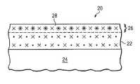
- a PDC cutter 20 in accordance with the present inventionincludes a diamond table 22 mounted to a substrate 24 .
- the diamond table 22is formed of diamond crystals (designated by “x”) sintered together at high pressure and temperature in the presence of a liquid metal catalyst (designated by “•”), most commonly cobalt.
- the “x” and “•” representationsare illustrative in nature, and are not presented to illustrate the actual crystallographic structure of the diamond table, but rather to show the distributed presence of the diamond crystals “x” and interstitial cobalt “•” binder within the diamond table.
- the substrate 24is typically formed of tungsten carbide, and is optional (i.e., the diamond table could be a free standing body if desired).
- the PDC cutter 20further includes, associated with its working face, a thermal channel 28 in which a less thermally expandable and/or more thermally conductive and/or lower heat capacity material (designated by “*”, and referred to herein as the “material”) is present.
- the starting pointis a PDC cutter as shown in FIG. 1 , and the material (designated by “*”) is introduced, for example through overlay, infusion, migration, and/or implantation, into the front face to comingle with, semi-alloy with and/or displace the synthesizing cobalt catalyst material to a desired depth 26 .
- the “x”, “•” and “*” representationsare illustrative in nature, and are not presented to illustrate the actual crystallographic structure of the diamond table, but rather to show the distributed presence of the material “*” in the thermal channel 28 with respect to the diamond crystals “x” and interstitial cobalt “•” binder of the diamond table 22 .
- the thermal channel 28is defined by the depth 26 to which the material extends from the front face or top surface of the diamond table. It will be noted that the material need not completely displace or drive away substantially all of the interstitial cobalt binder in the thermal channel 28 . Some alloying, comingling or mixing in the thermal channel of the material and the cobalt binder is permitted.
- the presence of the material to the depth 26presents a thermal channel 28 whose thermal properties are superior to the FIG. 2 channel 18 provided solely by leaching the interstitial cobalt out of the diamond table.
- the improved thermal conductivity in the channel 28reduces the risk of 1) stresses resulting from differential thermal expansion between the diamond and the residual metal inclusions along the diamond grain boundaries, and/or 2) a chemical reaction of the diamond to the cobalt turning the diamond back to graphite.
- the material in this applicationfor example, mixes, comingles or semi-alloys with the cobalt binder.
- the materialmay, for example, displace some of the cobalt binder at some to many of the interstitial locations in the diamond crystal structure.
- the cobaltis not removed, but rather migrates elsewhere (in the diamond table or to the tungsten carbide substrate), or is comingled or alloyed with the material.
- the depth 26may, for example, range from 0.020 mm to 0.6 mm.
- the thermal diffusivity (the ratio of thermal conductivity to volumetric heat capacity) of the thermal channel 28is increased. This can be accomplished by increasing the numerator of the ratio (for example, through the presence of a material with higher thermal conductivity) or decreasing the denominator of the ratio (for example, through the presence of a material with lower specific heat capacity), or a combination of both of increasing the numerator and decreasing the denominator. It is noted that leaching out the cobalt binder causes thermal conductivity to increase by about 2% while heat capacity drops by about 63% producing an overall increase in diffusivity of about 43%. This explains, to some degree, the advantage of a leached diamond table (see, FIG. 2 ).
- Overlay, infusion, migration, and/or implantation of the materialis designed to provide for still further improvement (increase) in diffusivity where the chosen material contributes to effectively increasing the numerator and/or decreasing the denominator of the thermal diffusivity ratio with respect to the thermal channel 28 .
- the materialmay be provided over the entire top surface (front face) of the diamond table 22 (see, FIG. 4 ), or be provided in accordance with a desired pattern on the top surface (front face) of the diamond table 22 (see, FIG. 5 ).
- the pattern selected for material inclusionmay assist in more efficiently channeling heat from a cutting tip across the diamond table. This pattern may be provided by the use of conventional masking techniques.
- the materialis provided with a pattern as shown in the FIG. 5 comprising a plurality of radially extending regions which include material to the desired depth.
- a material candidate for use in this applicationis cubic boron nitride, which has a thermal conductivity greater than 200 W m ⁇ 1 K ⁇ 1 (see, Nature volume 337, Jan. 26, 1989) and thermal expansion coefficient of 1.2 ⁇ m m ⁇ 1 K ⁇ 1 . These thermal properties are comparable to and compatible with the thermal properties of diamond, and are an improvement over the thermal properties of interstitial voids (as would be pertinent in the cobalt leached cutter of FIG. 2 ).
- thermal and mechanical performance of the thermal channel 28would be experienced from use of the cubic boron nitride as a coating or overlay material supporting the infusion, migration and/or introduction of boron into the diamond table to comingle and/or semi-alloy with, or alternatively displace some of, the synthesizing catalyst material (such as, cobalt) to a desired depth.
- the synthesizing catalyst materialsuch as, cobalt
- elemental material candidates for use in this applicationinclude: carbon, germanium, zinc, aluminum, silicon, molybdenum, boron, phosphorous, copper, silver, and gold. Combinations of these elements with other elements as well as alloys including one or more of these elements may be used as the material. Again, these materials each possess thermal properties comparable to and compatible with the thermal properties of diamond, and if interstitially included within the diamond table would present an improvement over the thermal properties of interstitial voids (as would be pertinent in the cobalt leached cutter of FIG. 2 ).
- Another material candidate for use in this applicationalternatively comprises one or more alkali earth carbonates such as Li 2 CO 3 , NaCO 3 , MgCO 3 , SrCO 3 , K 2 CO 3 , and the like.
- Another material candidate for use in this applicationalternatively comprises one or more sulfate such as Na 2 SO 4 , MgSO 4 , CaSO 4 , and the like.
- Another material candidate for use in this applicationalternatively comprises one or more hydroxide such as Mg(OH) 2 , Ca(OH) 2 , and the like.
- Another material candidate for use in this applicationalternatively comprises tungsten oxide (WO 3 ).
- Another material candidate for use in this applicationalternatively comprises boron carbide (B 4 C).
- Another material candidate for use in this applicationalternatively comprises TiC 0.6 .
- Another material candidate for use in this applicationalternatively comprises one or more iron oxide or double oxide such as FeTiO 3 , Fe 2 , SiO 4 , Y 3 Fe 5 O 12 , Fe 5 O 12 , and the like.
- Another material candidate for use in this applicationalternatively comprises one or more intermetallic materials.
- Another material candidate for use in this applicationalternatively comprises one or more ceramic materials.
- a number of different methodsmay be used to manufacture the PDC cutter 20 .
- a coating of the material 30(also referred to as “thermal channel material”) is applied to the front surface of the diamond table shown in FIG. 1 . This is shown in FIG. 6 .
- a number of techniquesmay be used for applying the material to the front surface of a target diamond table including: painting, coating, soaking, dipping, plasma vapor deposition, chemical vapor deposition, and plasma enhanced chemical vapor deposition.
- a treatmentis then performed which causes that material 30 (or specific components within that material) to comingle with the synthesizing catalyst material (such as, cobalt), semi-alloy with the synthesizing catalyst material, or partially migrate into the diamond table to perhaps displace some of the synthesizing catalyst material, in a near surface region 32 of the diamond table forming the thermal channel 28 .
- the synthesizing catalyst materialsuch as, cobalt
- semi-alloy with the synthesizing catalyst materialor partially migrate into the diamond table to perhaps displace some of the synthesizing catalyst material, in a near surface region 32 of the diamond table forming the thermal channel 28 .
- the unreacted material 30may be removed, if desired.
- the treatment usedcomprises an imbibition treatment.
- Imbibition treatment processesare disclosed in Published U.S. Applications for Patent 2008/0240879 and 2009/0032169, the disclosures of which are hereby incorporated by reference. These imbibition processes are disclosed in connection with effectuating cobalt migration in tungsten carbide substrates, but are believed to be pertinent as well to effectuating an introduction or migration of the material (or specific components within that material) from the front surface of the diamond table to a desired depth.
- the introduced material (or specific components within that material)may comingle with and/or semi-alloy with the synthesizing catalyst material (such as, cobalt) in the near surface region 32 of the diamond table.
- the introduction or migration of the material (or specific components within that material) through imbibitionmay also result in the displacement of some of the interstitial synthesizing catalyst material (such as, cobalt) in the near surface region 32 of the diamond table.
- the treatment usedcomprises a Hot Isostatic Pressing (HIPing) treatment.
- HIPingHot Isostatic Pressing
- This processsubjects a component to both elevated temperature and isostatic gas pressure in a high pressure containment vessel.
- the elevated temperature and isostatic gas pressureare believed useful to effectuating the introduction of the material (or specific components within that material) in the front face of the diamond table.
- the tungsten carbide substrate and a portion of the diamond layer closest to the tungsten carbide substratemay be encased or masked to preclude treatment of these areas, reserving the treatment to the working face of the diamond layer.
- the cobaltexpands at a rate that allows the cubic boron nitride material (or specific components such as elemental boron within that material) to diffuse and to fill the interstitial pores under the effect of the isostatic pressure. While filling these pores, the material (or specific components within that material) will react with the cobalt and the carbon to form a mix of (B, Co, C). The nature of the mix will depend on the temperature and the reaction of the boron.
- the treatment usedcomprises a cold pressing or cryogenic treatment.
- FIG. 8illustrates an implementation of this treatment in which the material coated front surface of the diamond table is held in a liquid nitrogen chamber for a selected period of time and vacuum environment.
- a heated shellis used to hold the tungsten carbide substrate and provide some protection against damage to the tungsten carbide substrate and/or the diamond table bond due to the extreme cold of the liquid nitrogen chamber.
- the cold temperature and vacuum pressureare believed to facilitate the introduction of the material (or specific components within that material) in the front face of the diamond table.
- micronized particles of the materialcan be pressed into the face of the diamond layer with a piston mechanism to further effect the entrance of the material (or specific components within that material) into the diamond layer.
- the thermal contraction of the cobalt within the face of the diamond layer brought about by the cryogenic environmentenhances the infusion of the material (or specific components within that material) into the face of the diamond layer.
- the treatment usedcomprises spark plasma sintering, or field assisted sintering or pulsed electric current sintering. Details concerning these processes are known to those skilled in the art (see, for example, Shen, “Spark Plasma Sintering Assisted Diamond Formation From Carbon Nanotubes At Very Low Pressure,” 2006 Nanotechnology 17 pages 2187-2191 (2206), the disclosure of which is incorporated by reference).
- the application of the pulsed current of the sintering techniquecauses localized heating at high rates with the heat facilitating migration of the material (or components of the material) into the thermal channel for comingling, semi-alloying, or partially migrating and displacing some of the synthesizing catalyst material (such as, cobalt).
- the plasma vapor deposition, chemical vapor deposition, and plasma enhanced chemical vapor deposition used to coat the front surface of the diamond tableprovides for some penetration of the material (or specific components within that material) into the diamond table for comingling, semi-alloying, or partially migrating and displacing some of the synthesizing catalyst material (such as, cobalt).
- the materialis heated at a temperature high enough to be vaporized and to be condensed at a temperature below the previous temperature but above 750° C. While submitted to temperature above 750° C., the interstitial catalyst binder expands at a rate that allows the vapor of the material (or components of the material) to diffuse and to fill the interstitial pores created by the expansion of the catalyst binder. While filling these pores, the material (or components of the material) will react with the catalyst binder and the carbon to form a mix of materials. The nature of the mix will depend on the temperature and the reaction of the material (or components of the material).
- no coating with the materialis performed. Instead, the material is selected because it is especially well suited to ion implantation.
- the selection of boron or phosphorous (or other known p-type or n-type dopants) as likely candidates for ion implantationis preferred as the use of these dopant species is well known from the field of semiconductor integrated circuit fabrication.
- a PDC cutter as shown in FIG. 1is placed within an ion implantation chamber and ions of a selected type comprising the material are implanted at high energy for comingling and/or semi-alloying with the synthesizing catalyst material (such as, cobalt).
- the ion implantationmay cause displacement of some of the synthesizing catalyst material (such as, cobalt), and allow the ions to occupy vacant interstitial locations.
- the ion implantationcould alternatively assist migrating material atoms into the diamond table.
- An annealing heat treatmentmay be performed following implantation to further diffuse the dopant species and/or repair damage to the diamond crystal structure which results from the implantation.
Landscapes
- Chemical & Material Sciences (AREA)
- Engineering & Computer Science (AREA)
- Materials Engineering (AREA)
- Mechanical Engineering (AREA)
- Organic Chemistry (AREA)
- Mining & Mineral Resources (AREA)
- Metallurgy (AREA)
- Life Sciences & Earth Sciences (AREA)
- Geology (AREA)
- Physics & Mathematics (AREA)
- General Life Sciences & Earth Sciences (AREA)
- Geochemistry & Mineralogy (AREA)
- Chemical Kinetics & Catalysis (AREA)
- Fluid Mechanics (AREA)
- Environmental & Geological Engineering (AREA)
- Crystallography & Structural Chemistry (AREA)
- Earth Drilling (AREA)
- Crystals, And After-Treatments Of Crystals (AREA)
- Carbon And Carbon Compounds (AREA)
- Cutting Tools, Boring Holders, And Turrets (AREA)
- Catalysts (AREA)
Abstract
Description
Claims (34)
Priority Applications (4)
| Application Number | Priority Date | Filing Date | Title |
|---|---|---|---|
| US12/716,251US8365846B2 (en) | 2009-03-27 | 2010-03-02 | Polycrystalline diamond cutter with high thermal conductivity |
| EP10756900.6AEP2411617A4 (en) | 2009-03-27 | 2010-03-26 | Polycrystalline diamond cutter with high thermal conductivity |
| PCT/US2010/028810WO2010111580A1 (en) | 2009-03-27 | 2010-03-26 | Polycrystalline diamond cutter with high thermal conductivity |
| RU2011107307/03ARU2520319C2 (en) | 2009-03-27 | 2010-03-26 | Cutter of polycrystalline diamond with high heat conductivity |
Applications Claiming Priority (2)
| Application Number | Priority Date | Filing Date | Title |
|---|---|---|---|
| US16410409P | 2009-03-27 | 2009-03-27 | |
| US12/716,251US8365846B2 (en) | 2009-03-27 | 2010-03-02 | Polycrystalline diamond cutter with high thermal conductivity |
Publications (2)
| Publication Number | Publication Date |
|---|---|
| US20100243335A1 US20100243335A1 (en) | 2010-09-30 |
| US8365846B2true US8365846B2 (en) | 2013-02-05 |
Family
ID=42781538
Family Applications (1)
| Application Number | Title | Priority Date | Filing Date |
|---|---|---|---|
| US12/716,251Expired - Fee RelatedUS8365846B2 (en) | 2009-03-27 | 2010-03-02 | Polycrystalline diamond cutter with high thermal conductivity |
Country Status (4)
| Country | Link |
|---|---|
| US (1) | US8365846B2 (en) |
| EP (1) | EP2411617A4 (en) |
| RU (1) | RU2520319C2 (en) |
| WO (1) | WO2010111580A1 (en) |
Cited By (17)
| Publication number | Priority date | Publication date | Assignee | Title |
|---|---|---|---|---|
| US20110266059A1 (en)* | 2010-04-28 | 2011-11-03 | Element Six (Production) (Pty) Ltd | Polycrystalline diamond compacts, cutting elements and earth-boring tools including such compacts, and methods of forming such compacts and earth-boring tools |
| US9539703B2 (en) | 2013-03-15 | 2017-01-10 | Smith International, Inc. | Carbonate PCD with a distribution of Si and/or Al |
| US9539704B2 (en) | 2013-03-15 | 2017-01-10 | Smith International, Inc. | Carbonate PCD and methods of making the same |
| US10968991B2 (en) | 2018-07-30 | 2021-04-06 | XR Downhole, LLC | Cam follower with polycrystalline diamond engagement element |
| US11014759B2 (en) | 2018-07-30 | 2021-05-25 | XR Downhole, LLC | Roller ball assembly with superhard elements |
| US11035407B2 (en) | 2018-07-30 | 2021-06-15 | XR Downhole, LLC | Material treatments for diamond-on-diamond reactive material bearing engagements |
| US11054000B2 (en) | 2018-07-30 | 2021-07-06 | Pi Tech Innovations Llc | Polycrystalline diamond power transmission surfaces |
| US11187040B2 (en) | 2018-07-30 | 2021-11-30 | XR Downhole, LLC | Downhole drilling tool with a polycrystalline diamond bearing |
| US11225842B2 (en) | 2018-08-02 | 2022-01-18 | XR Downhole, LLC | Polycrystalline diamond tubular protection |
| US11242891B2 (en) | 2018-07-30 | 2022-02-08 | XR Downhole, LLC | Polycrystalline diamond radial bearing |
| US11286985B2 (en) | 2018-07-30 | 2022-03-29 | Xr Downhole Llc | Polycrystalline diamond bearings for rotating machinery with compliance |
| US11371556B2 (en) | 2018-07-30 | 2022-06-28 | Xr Reserve Llc | Polycrystalline diamond linear bearings |
| US11603715B2 (en) | 2018-08-02 | 2023-03-14 | Xr Reserve Llc | Sucker rod couplings and tool joints with polycrystalline diamond elements |
| US11614126B2 (en) | 2020-05-29 | 2023-03-28 | Pi Tech Innovations Llc | Joints with diamond bearing surfaces |
| US11655850B2 (en) | 2020-11-09 | 2023-05-23 | Pi Tech Innovations Llc | Continuous diamond surface bearings for sliding engagement with metal surfaces |
| US12006973B2 (en) | 2020-11-09 | 2024-06-11 | Pi Tech Innovations Llc | Diamond surface bearings for sliding engagement with metal surfaces |
| US12228177B2 (en) | 2020-05-29 | 2025-02-18 | Pi Tech Innovations Llc | Driveline with double conical bearing joints having polycrystalline diamond power transmission surfaces |
Families Citing this family (8)
| Publication number | Priority date | Publication date | Assignee | Title |
|---|---|---|---|---|
| WO2011017649A2 (en)* | 2009-08-07 | 2011-02-10 | Baker Hughes Incorporated | Polycrystalline compacts including in-situ nucleated grains earth-boring tools including such compacts, and methods of forming such compacts and tools |
| US8727042B2 (en) | 2009-09-11 | 2014-05-20 | Baker Hughes Incorporated | Polycrystalline compacts having material disposed in interstitial spaces therein, and cutting elements including such compacts |
| EP2488719B8 (en) | 2009-10-15 | 2019-06-26 | Baker Hughes, a GE company, LLC | Polycrystalline compacts including nanoparticulate inclusions, cutting elements and earth-boring tools including such compacts, and methods of forming such compacts |
| EP2638234B1 (en) | 2010-11-08 | 2019-03-06 | Baker Hughes, a GE company, LLC | Polycrystalline compacts including nanoparticulate inclusions, cutting elements and earth-boring tools including such compacts, and methods of forming same |
| US9422770B2 (en) | 2011-12-30 | 2016-08-23 | Smith International, Inc. | Method for braze joining of carbonate PCD |
| US9482056B2 (en)* | 2011-12-30 | 2016-11-01 | Smith International, Inc. | Solid PCD cutter |
| US9068260B2 (en) | 2012-03-14 | 2015-06-30 | Andritz Iggesund Tools Inc. | Knife for wood processing and methods for plating and surface treating a knife for wood processing |
| RU2744213C1 (en)* | 2020-04-29 | 2021-03-03 | Олег Викторович Барзинский | Cutting element for equipping drill bits |
Citations (49)
| Publication number | Priority date | Publication date | Assignee | Title |
|---|---|---|---|---|
| US4016736A (en) | 1975-06-25 | 1977-04-12 | General Electric Company | Lubricant packed wire drawing dies |
| US4124401A (en) | 1977-10-21 | 1978-11-07 | General Electric Company | Polycrystalline diamond body |
| US4184079A (en) | 1977-05-26 | 1980-01-15 | National Research Development Corporation | Radiation toughening of diamonds |
| US4536442A (en) | 1979-08-23 | 1985-08-20 | General Electric Company | Process for making diamond and cubic boron nitride compacts |
| US4605343A (en) | 1984-09-20 | 1986-08-12 | General Electric Company | Sintered polycrystalline diamond compact construction with integral heat sink |
| US4664705A (en) | 1985-07-30 | 1987-05-12 | Sii Megadiamond, Inc. | Infiltrated thermally stable polycrystalline diamond |
| US4940180A (en) | 1988-08-04 | 1990-07-10 | Martell Trevor J | Thermally stable diamond abrasive compact body |
| US4995887A (en) | 1988-04-05 | 1991-02-26 | Reed Tool Company Limited | Cutting elements for rotary drill bits |
| US5078551A (en) | 1989-09-18 | 1992-01-07 | U.S. Philips Corporation | Diamond tool |
| US5127923A (en) | 1985-01-10 | 1992-07-07 | U.S. Synthetic Corporation | Composite abrasive compact having high thermal stability |
| US5277940A (en) | 1990-10-29 | 1994-01-11 | Diamond Technologies Company | Method for treating diamonds to produce bondable diamonds for depositing same on a substrate |
| US5379854A (en) | 1993-08-17 | 1995-01-10 | Dennis Tool Company | Cutting element for drill bits |
| US5609926A (en) | 1994-03-21 | 1997-03-11 | Prins; Johan F. | Diamond doping |
| US5645617A (en) | 1995-09-06 | 1997-07-08 | Frushour; Robert H. | Composite polycrystalline diamond compact with improved impact and thermal stability |
| US5647878A (en) | 1994-08-04 | 1997-07-15 | General Electric Company | Fabrication of brazable in air diamond tool inserts and inserts fabricated thereby |
| US5769986A (en) | 1996-08-13 | 1998-06-23 | Northrop Grumman Corporation | Stress-free bonding of dissimilar materials |
| US5857889A (en) | 1996-03-27 | 1999-01-12 | Thermoceramix, Llc | Arc Chamber for an ion implantation system |
| US6068913A (en) | 1997-09-18 | 2000-05-30 | Sid Co., Ltd. | Supported PCD/PCBN tool with arched intermediate layer |
| US6258139B1 (en) | 1999-12-20 | 2001-07-10 | U S Synthetic Corporation | Polycrystalline diamond cutter with an integral alternative material core |
| WO2001079583A2 (en) | 2000-04-14 | 2001-10-25 | Technology International, Inc. | Diamonds having improved durability |
| US20020014041A1 (en)* | 2000-06-30 | 2002-02-07 | Baldoni J. Gary | Process for coating superabrasive with metal |
| US6443248B2 (en) | 1999-04-16 | 2002-09-03 | Smith International, Inc. | Drill bit inserts with interruption in gradient of properties |
| US6663682B2 (en) | 2000-06-30 | 2003-12-16 | Saint-Gobain Abrasives Technology Company | Article of superabrasive coated with metal |
| US6779951B1 (en) | 2000-02-16 | 2004-08-24 | U.S. Synthetic Corporation | Drill insert using a sandwiched polycrystalline diamond compact and method of making the same |
| US20050050801A1 (en) | 2003-09-05 | 2005-03-10 | Cho Hyun Sam | Doubled-sided and multi-layered PCD and PCBN abrasive articles |
| US6887144B2 (en) | 1996-11-12 | 2005-05-03 | Diamond Innovations, Inc. | Surface impurity-enriched diamond and method of making |
| US20050137078A1 (en) | 2003-12-18 | 2005-06-23 | 3M Innovative Properties Company | Alumina-yttria particles and methods of making the same |
| US7008672B2 (en) | 1998-09-28 | 2006-03-07 | Skeleton Technologies Ag | Method of manufacturing a diamond composite and a composite produced by same |
| US20060060392A1 (en) | 2004-09-21 | 2006-03-23 | Smith International, Inc. | Thermally stable diamond polycrystalline diamond constructions |
| US20060157285A1 (en) | 2005-01-17 | 2006-07-20 | Us Synthetic Corporation | Polycrystalline diamond insert, drill bit including same, and method of operation |
| US20070079994A1 (en)* | 2005-10-12 | 2007-04-12 | Smith International, Inc. | Diamond-bonded bodies and compacts with improved thermal stability and mechanical strength |
| US20070187155A1 (en)* | 2006-02-09 | 2007-08-16 | Smith International, Inc. | Thermally stable ultra-hard polycrystalline materials and compacts |
| US20070278017A1 (en) | 2006-05-30 | 2007-12-06 | Smith International, Inc. | Rolling cutter |
| US20080073126A1 (en) | 2006-09-21 | 2008-03-27 | Smith International, Inc. | Polycrystalline diamond composites |
| US20080073127A1 (en) | 2006-09-21 | 2008-03-27 | Smith International, Inc. | Atomic layer deposition nanocoatings on cutting tool powder materials |
| US7350601B2 (en) | 2005-01-25 | 2008-04-01 | Smith International, Inc. | Cutting elements formed from ultra hard materials having an enhanced construction |
| US20080098659A1 (en) | 2006-10-26 | 2008-05-01 | Chien-Min Sung | Methods for securing individual abrasive particles to a substrate in a predetermined pattern |
| US20080115421A1 (en)* | 2006-11-20 | 2008-05-22 | Us Synthetic Corporation | Methods of fabricating superabrasive articles |
| US20080115424A1 (en)* | 2004-09-23 | 2008-05-22 | Element Six (Pty) Ltd | Polycrystalline Abrasive Materials and Method of Manufacture |
| US7377341B2 (en) | 2005-05-26 | 2008-05-27 | Smith International, Inc. | Thermally stable ultra-hard material compact construction |
| US20080142276A1 (en) | 2006-05-09 | 2008-06-19 | Smith International, Inc. | Thermally stable ultra-hard material compact constructions |
| US20080223623A1 (en) | 2007-02-06 | 2008-09-18 | Smith International, Inc. | Polycrystalline diamond constructions having improved thermal stability |
| US20080230280A1 (en) | 2007-03-21 | 2008-09-25 | Smith International, Inc. | Polycrystalline diamond having improved thermal stability |
| US20080302579A1 (en) | 2007-06-05 | 2008-12-11 | Smith International, Inc. | Polycrystalline diamond cutting elements having improved thermal resistance |
| US20080308276A1 (en) | 2007-06-15 | 2008-12-18 | Baker Hughes Incorporated | Cutting elements for casing component drill out and subterranean drilling, earth boring drag bits and tools including same and methods of use |
| US20090090563A1 (en) | 2007-10-04 | 2009-04-09 | Smith International, Inc. | Diamond-bonded constrcutions with improved thermal and mechanical properties |
| US20090218276A1 (en)* | 2008-02-29 | 2009-09-03 | Brigham Young University | Functionalized diamond particles and methods for preparing the same |
| US7635035B1 (en) | 2005-08-24 | 2009-12-22 | Us Synthetic Corporation | Polycrystalline diamond compact (PDC) cutting element having multiple catalytic elements |
| US20100108403A1 (en) | 2008-11-06 | 2010-05-06 | Smith International, Inc. | Surface coatings on cutting elements |
Family Cites Families (9)
| Publication number | Priority date | Publication date | Assignee | Title |
|---|---|---|---|---|
| US453442A (en)* | 1891-06-02 | Cash-fare ticket for railroads | ||
| GB8505352D0 (en)* | 1985-03-01 | 1985-04-03 | Nl Petroleum Prod | Cutting elements |
| JP3400464B2 (en)* | 1991-09-30 | 2003-04-28 | 住友電気工業株式会社 | Diamond polycrystalline cutting tool and method of manufacturing the same |
| US5337844A (en)* | 1992-07-16 | 1994-08-16 | Baker Hughes, Incorporated | Drill bit having diamond film cutting elements |
| EP1190791B1 (en)* | 2000-09-20 | 2010-06-23 | Camco International (UK) Limited | Polycrystalline diamond cutters with working surfaces having varied wear resistance while maintaining impact strength |
| JP4676700B2 (en)* | 2002-01-30 | 2011-04-27 | エレメント シックス (プロプライエタリイ)リミテッド | Abrasive layered green compact |
| JP3899402B2 (en)* | 2002-08-26 | 2007-03-28 | 独立行政法人物質・材料研究機構 | Method for producing diamond-titanium carbide composite sintered body |
| US20100275523A1 (en)* | 2007-03-22 | 2010-11-04 | Klaus Tank | Abrasive compacts |
| US8858871B2 (en)* | 2007-03-27 | 2014-10-14 | Varel International Ind., L.P. | Process for the production of a thermally stable polycrystalline diamond compact |
- 2010
- 2010-03-02USUS12/716,251patent/US8365846B2/ennot_activeExpired - Fee Related
- 2010-03-26WOPCT/US2010/028810patent/WO2010111580A1/enactiveApplication Filing
- 2010-03-26EPEP10756900.6Apatent/EP2411617A4/ennot_activeWithdrawn
- 2010-03-26RURU2011107307/03Apatent/RU2520319C2/ennot_activeIP Right Cessation
Patent Citations (50)
| Publication number | Priority date | Publication date | Assignee | Title |
|---|---|---|---|---|
| US4016736A (en) | 1975-06-25 | 1977-04-12 | General Electric Company | Lubricant packed wire drawing dies |
| US4184079A (en) | 1977-05-26 | 1980-01-15 | National Research Development Corporation | Radiation toughening of diamonds |
| US4124401A (en) | 1977-10-21 | 1978-11-07 | General Electric Company | Polycrystalline diamond body |
| US4536442A (en) | 1979-08-23 | 1985-08-20 | General Electric Company | Process for making diamond and cubic boron nitride compacts |
| US4605343A (en) | 1984-09-20 | 1986-08-12 | General Electric Company | Sintered polycrystalline diamond compact construction with integral heat sink |
| US5127923A (en) | 1985-01-10 | 1992-07-07 | U.S. Synthetic Corporation | Composite abrasive compact having high thermal stability |
| US4664705A (en) | 1985-07-30 | 1987-05-12 | Sii Megadiamond, Inc. | Infiltrated thermally stable polycrystalline diamond |
| US4995887A (en) | 1988-04-05 | 1991-02-26 | Reed Tool Company Limited | Cutting elements for rotary drill bits |
| US5025874A (en) | 1988-04-05 | 1991-06-25 | Reed Tool Company Ltd. | Cutting elements for rotary drill bits |
| US4940180A (en) | 1988-08-04 | 1990-07-10 | Martell Trevor J | Thermally stable diamond abrasive compact body |
| US5078551A (en) | 1989-09-18 | 1992-01-07 | U.S. Philips Corporation | Diamond tool |
| US5277940A (en) | 1990-10-29 | 1994-01-11 | Diamond Technologies Company | Method for treating diamonds to produce bondable diamonds for depositing same on a substrate |
| US5379854A (en) | 1993-08-17 | 1995-01-10 | Dennis Tool Company | Cutting element for drill bits |
| US5609926A (en) | 1994-03-21 | 1997-03-11 | Prins; Johan F. | Diamond doping |
| US5647878A (en) | 1994-08-04 | 1997-07-15 | General Electric Company | Fabrication of brazable in air diamond tool inserts and inserts fabricated thereby |
| US5645617A (en) | 1995-09-06 | 1997-07-08 | Frushour; Robert H. | Composite polycrystalline diamond compact with improved impact and thermal stability |
| US5857889A (en) | 1996-03-27 | 1999-01-12 | Thermoceramix, Llc | Arc Chamber for an ion implantation system |
| US5769986A (en) | 1996-08-13 | 1998-06-23 | Northrop Grumman Corporation | Stress-free bonding of dissimilar materials |
| US6887144B2 (en) | 1996-11-12 | 2005-05-03 | Diamond Innovations, Inc. | Surface impurity-enriched diamond and method of making |
| US6068913A (en) | 1997-09-18 | 2000-05-30 | Sid Co., Ltd. | Supported PCD/PCBN tool with arched intermediate layer |
| US7008672B2 (en) | 1998-09-28 | 2006-03-07 | Skeleton Technologies Ag | Method of manufacturing a diamond composite and a composite produced by same |
| US6443248B2 (en) | 1999-04-16 | 2002-09-03 | Smith International, Inc. | Drill bit inserts with interruption in gradient of properties |
| US6258139B1 (en) | 1999-12-20 | 2001-07-10 | U S Synthetic Corporation | Polycrystalline diamond cutter with an integral alternative material core |
| US6779951B1 (en) | 2000-02-16 | 2004-08-24 | U.S. Synthetic Corporation | Drill insert using a sandwiched polycrystalline diamond compact and method of making the same |
| WO2001079583A2 (en) | 2000-04-14 | 2001-10-25 | Technology International, Inc. | Diamonds having improved durability |
| US6663682B2 (en) | 2000-06-30 | 2003-12-16 | Saint-Gobain Abrasives Technology Company | Article of superabrasive coated with metal |
| US20020014041A1 (en)* | 2000-06-30 | 2002-02-07 | Baldoni J. Gary | Process for coating superabrasive with metal |
| US20050050801A1 (en) | 2003-09-05 | 2005-03-10 | Cho Hyun Sam | Doubled-sided and multi-layered PCD and PCBN abrasive articles |
| US20050137078A1 (en) | 2003-12-18 | 2005-06-23 | 3M Innovative Properties Company | Alumina-yttria particles and methods of making the same |
| US20060060392A1 (en) | 2004-09-21 | 2006-03-23 | Smith International, Inc. | Thermally stable diamond polycrystalline diamond constructions |
| US20080115424A1 (en)* | 2004-09-23 | 2008-05-22 | Element Six (Pty) Ltd | Polycrystalline Abrasive Materials and Method of Manufacture |
| US20060157285A1 (en) | 2005-01-17 | 2006-07-20 | Us Synthetic Corporation | Polycrystalline diamond insert, drill bit including same, and method of operation |
| US7350601B2 (en) | 2005-01-25 | 2008-04-01 | Smith International, Inc. | Cutting elements formed from ultra hard materials having an enhanced construction |
| US7377341B2 (en) | 2005-05-26 | 2008-05-27 | Smith International, Inc. | Thermally stable ultra-hard material compact construction |
| US7635035B1 (en) | 2005-08-24 | 2009-12-22 | Us Synthetic Corporation | Polycrystalline diamond compact (PDC) cutting element having multiple catalytic elements |
| US20070079994A1 (en)* | 2005-10-12 | 2007-04-12 | Smith International, Inc. | Diamond-bonded bodies and compacts with improved thermal stability and mechanical strength |
| US20070187155A1 (en)* | 2006-02-09 | 2007-08-16 | Smith International, Inc. | Thermally stable ultra-hard polycrystalline materials and compacts |
| US20080142276A1 (en) | 2006-05-09 | 2008-06-19 | Smith International, Inc. | Thermally stable ultra-hard material compact constructions |
| US20070278017A1 (en) | 2006-05-30 | 2007-12-06 | Smith International, Inc. | Rolling cutter |
| US20080073126A1 (en) | 2006-09-21 | 2008-03-27 | Smith International, Inc. | Polycrystalline diamond composites |
| US20080073127A1 (en) | 2006-09-21 | 2008-03-27 | Smith International, Inc. | Atomic layer deposition nanocoatings on cutting tool powder materials |
| US20080098659A1 (en) | 2006-10-26 | 2008-05-01 | Chien-Min Sung | Methods for securing individual abrasive particles to a substrate in a predetermined pattern |
| US20080115421A1 (en)* | 2006-11-20 | 2008-05-22 | Us Synthetic Corporation | Methods of fabricating superabrasive articles |
| US20080223623A1 (en) | 2007-02-06 | 2008-09-18 | Smith International, Inc. | Polycrystalline diamond constructions having improved thermal stability |
| US20080230280A1 (en) | 2007-03-21 | 2008-09-25 | Smith International, Inc. | Polycrystalline diamond having improved thermal stability |
| US20080302579A1 (en) | 2007-06-05 | 2008-12-11 | Smith International, Inc. | Polycrystalline diamond cutting elements having improved thermal resistance |
| US20080308276A1 (en) | 2007-06-15 | 2008-12-18 | Baker Hughes Incorporated | Cutting elements for casing component drill out and subterranean drilling, earth boring drag bits and tools including same and methods of use |
| US20090090563A1 (en) | 2007-10-04 | 2009-04-09 | Smith International, Inc. | Diamond-bonded constrcutions with improved thermal and mechanical properties |
| US20090218276A1 (en)* | 2008-02-29 | 2009-09-03 | Brigham Young University | Functionalized diamond particles and methods for preparing the same |
| US20100108403A1 (en) | 2008-11-06 | 2010-05-06 | Smith International, Inc. | Surface coatings on cutting elements |
Non-Patent Citations (9)
| Title |
|---|
| International Search Report, International Application No. PCT/US2010/028807, May 25, 2010. |
| International Search Report, International Application No. PCT/US2010/028810, May 20, 2010. |
| Ortega et al., "Frictional Heating and Convective Cooling of Polycrystalline Diamond Drag Tools During Rock Cutting", Society of Pertoleum Engineers Journal, 0197-7520/84/004-1061$00.25, Apr. 1984, pp. 121-128. |
| Shen et al., "Spark Plasma Sintering Assisted Diamond Formation from Carbon Nanotubes at Very Low Pressure", Institute of Physics Publishing, Nanotechnology 17 (2006) pp. 2187-2191. |
| Spark Plasma Sintering, http://en.wikipedia.org/wiki/Spark-plasma-sintering, Feb. 17, 2010, p. 1 of 1. |
| Thermal Technology LLC, High Temperature Experts, Newsflash "Spark Plasma Sintering, SPS Technology", Feb. 17, 2010, http://www.thermaltechnologyinc.com/index.php?option=com-content&view=article&id=84, pp. 1-3. |
| Wang et al., "A Study on the Oxidation Resistance of Sintered Polycrystalline Diamond with Dopants", KTK Scientific Publishers/Terra Scientific Publishing Company, 1990, pp. 437-439. |
| Written Opinion of the International Searching Authority, International Application No. PCT/US2010/028807, May 25, 2010. |
| Written Opinion of the International Searching Authority, International Application No. PCT/US2010/028810, May 20, 2010. |
Cited By (34)
| Publication number | Priority date | Publication date | Assignee | Title |
|---|---|---|---|---|
| US20110266059A1 (en)* | 2010-04-28 | 2011-11-03 | Element Six (Production) (Pty) Ltd | Polycrystalline diamond compacts, cutting elements and earth-boring tools including such compacts, and methods of forming such compacts and earth-boring tools |
| US8839889B2 (en)* | 2010-04-28 | 2014-09-23 | Baker Hughes Incorporated | Polycrystalline diamond compacts, cutting elements and earth-boring tools including such compacts, and methods of forming such compacts and earth-boring tools |
| US9849561B2 (en) | 2010-04-28 | 2017-12-26 | Baker Hughes Incorporated | Cutting elements including polycrystalline diamond compacts for earth-boring tools |
| US9539703B2 (en) | 2013-03-15 | 2017-01-10 | Smith International, Inc. | Carbonate PCD with a distribution of Si and/or Al |
| US9539704B2 (en) | 2013-03-15 | 2017-01-10 | Smith International, Inc. | Carbonate PCD and methods of making the same |
| US10166655B2 (en) | 2013-03-15 | 2019-01-01 | Smith International, Inc. | Carbonate PCD with a distribution of Si and/or Al |
| US10442057B2 (en) | 2013-03-15 | 2019-10-15 | Smith International, Inc. | Carbonate PCD and methods of making the same |
| US11371556B2 (en) | 2018-07-30 | 2022-06-28 | Xr Reserve Llc | Polycrystalline diamond linear bearings |
| US11746875B2 (en) | 2018-07-30 | 2023-09-05 | Xr Reserve Llc | Cam follower with polycrystalline diamond engagement element |
| US11035407B2 (en) | 2018-07-30 | 2021-06-15 | XR Downhole, LLC | Material treatments for diamond-on-diamond reactive material bearing engagements |
| US11054000B2 (en) | 2018-07-30 | 2021-07-06 | Pi Tech Innovations Llc | Polycrystalline diamond power transmission surfaces |
| US11187040B2 (en) | 2018-07-30 | 2021-11-30 | XR Downhole, LLC | Downhole drilling tool with a polycrystalline diamond bearing |
| US11994006B2 (en) | 2018-07-30 | 2024-05-28 | Xr Reserve Llc | Downhole drilling tool with a polycrystalline diamond bearing |
| US11242891B2 (en) | 2018-07-30 | 2022-02-08 | XR Downhole, LLC | Polycrystalline diamond radial bearing |
| US11274731B2 (en) | 2018-07-30 | 2022-03-15 | Pi Tech Innovations Llc | Polycrystalline diamond power transmission surfaces |
| US11286985B2 (en) | 2018-07-30 | 2022-03-29 | Xr Downhole Llc | Polycrystalline diamond bearings for rotating machinery with compliance |
| US10968991B2 (en) | 2018-07-30 | 2021-04-06 | XR Downhole, LLC | Cam follower with polycrystalline diamond engagement element |
| US11499619B2 (en) | 2018-07-30 | 2022-11-15 | David P. Miess | Cam follower with polycrystalline diamond engagement element |
| US12281541B2 (en) | 2018-07-30 | 2025-04-22 | Xr Reserve, Llc | Downhole drilling tool with a polycrystalline diamond bearing |
| US11608858B2 (en) | 2018-07-30 | 2023-03-21 | Xr Reserve Llc | Material treatments for diamond-on-diamond reactive material bearing engagements |
| US11014759B2 (en) | 2018-07-30 | 2021-05-25 | XR Downhole, LLC | Roller ball assembly with superhard elements |
| US11655679B2 (en) | 2018-07-30 | 2023-05-23 | Xr Reserve Llc | Downhole drilling tool with a polycrystalline diamond bearing |
| US12326170B2 (en) | 2018-07-30 | 2025-06-10 | Xr Reserve Llc | Polycrystalline diamond radial bearing |
| US11970339B2 (en) | 2018-07-30 | 2024-04-30 | Xr Reserve Llc | Roller ball assembly with superhard elements |
| US11761481B2 (en) | 2018-07-30 | 2023-09-19 | Xr Reserve Llc | Polycrystalline diamond radial bearing |
| US11761486B2 (en) | 2018-07-30 | 2023-09-19 | Xr Reserve Llc | Polycrystalline diamond bearings for rotating machinery with compliance |
| US11603715B2 (en) | 2018-08-02 | 2023-03-14 | Xr Reserve Llc | Sucker rod couplings and tool joints with polycrystalline diamond elements |
| US11225842B2 (en) | 2018-08-02 | 2022-01-18 | XR Downhole, LLC | Polycrystalline diamond tubular protection |
| US11614126B2 (en) | 2020-05-29 | 2023-03-28 | Pi Tech Innovations Llc | Joints with diamond bearing surfaces |
| US12228177B2 (en) | 2020-05-29 | 2025-02-18 | Pi Tech Innovations Llc | Driveline with double conical bearing joints having polycrystalline diamond power transmission surfaces |
| US11906001B2 (en) | 2020-05-29 | 2024-02-20 | Pi Tech Innovations Llc | Joints with diamond bearing surfaces |
| US11933356B1 (en) | 2020-11-09 | 2024-03-19 | Pi Tech Innovations Llc | Continuous diamond surface bearings for sliding engagement with metal surfaces |
| US12006973B2 (en) | 2020-11-09 | 2024-06-11 | Pi Tech Innovations Llc | Diamond surface bearings for sliding engagement with metal surfaces |
| US11655850B2 (en) | 2020-11-09 | 2023-05-23 | Pi Tech Innovations Llc | Continuous diamond surface bearings for sliding engagement with metal surfaces |
Also Published As
| Publication number | Publication date |
|---|---|
| WO2010111580A1 (en) | 2010-09-30 |
| EP2411617A4 (en) | 2016-08-03 |
| US20100243335A1 (en) | 2010-09-30 |
| EP2411617A1 (en) | 2012-02-01 |
| RU2011107307A (en) | 2012-11-10 |
| RU2520319C2 (en) | 2014-06-20 |
Similar Documents
| Publication | Publication Date | Title |
|---|---|---|
| US8365846B2 (en) | Polycrystalline diamond cutter with high thermal conductivity | |
| US8662209B2 (en) | Backfilled polycrystalline diamond cutter with high thermal conductivity | |
| CA2533356C (en) | Cutting elements formed from ultra hard materials having an enhanced construction | |
| US8741006B2 (en) | Ultra-hard constructions with enhanced second phase | |
| US8771389B2 (en) | Methods of making and attaching TSP material for forming cutting elements, cutting elements having such TSP material and bits incorporating such cutting elements | |
| CN101275213B (en) | Method of manufacturing a part comprising at least one block made from a dense material | |
| US8083012B2 (en) | Diamond bonded construction with thermally stable region | |
| CN102844135B (en) | Polycrystalline diamond compact and related methods and applications | |
| US8080071B1 (en) | Polycrystalline diamond compact, methods of fabricating same, and applications therefor | |
| US8858871B2 (en) | Process for the production of a thermally stable polycrystalline diamond compact | |
| US9273381B2 (en) | Polycrystalline diamond compact including a carbonate-catalyzed polycrystalline diamond table and applications therefor | |
| US20110036643A1 (en) | Thermally stable polycrystalline diamond constructions | |
| CN102395694A (en) | Polycrystalline diamond element | |
| US20170157746A1 (en) | Methods of fabricating a polycrystalline diamond compact | |
| US20120048625A1 (en) | Functionally Leached PCD Cutter | |
| US11702741B2 (en) | Producing polycrystalline diamond compact cutters with coatings | |
| CN107206573A (en) | With superhard material cutting element and its manufacture method with metal intermediate layer |
Legal Events
| Date | Code | Title | Description |
|---|---|---|---|
| AS | Assignment | Owner name:VAREL INTERNATIONAL, IND., L.P., TEXAS Free format text:ASSIGNMENT OF ASSIGNORS INTEREST;ASSIGNORS:DOURFAYE, ALFAZAZI;REESE, MICHAEL;KING, WILLIAM W.;REEL/FRAME:024017/0692 Effective date:20100225 | |
| AS | Assignment | Owner name:LEHMAN COMMERCIAL PAPER INC., NEW YORK Free format text:SECURITY AGREEMENT;ASSIGNOR:VAREL INTERNATIONAL IND., L.P.;REEL/FRAME:024547/0944 Effective date:20100604 | |
| AS | Assignment | Owner name:DRILLBIT WCF LIMITED, CAYMAN ISLANDS Free format text:SECURITY AGREEMENT;ASSIGNOR:VAREL INTERNATIONAL IND., L.P.;REEL/FRAME:025877/0447 Effective date:20110228 | |
| AS | Assignment | Owner name:CREDIT SUISSE AG, CAYMAN ISLANDS BRANCH, NEW YORK Free format text:NOTICE OF SUBSTITUTION OF AGENT IN INTELLECTUAL PROPERTY;ASSIGNOR:LEHMAN COMMERCIAL PAPER INC.;REEL/FRAME:027127/0635 Effective date:20110913 | |
| AS | Assignment | Owner name:DRILLBIT WCF II LIMITED, CAYMAN ISLANDS Free format text:SECURITY AGREEMENT;ASSIGNOR:VAREL INTERNATIONAL IND., L.P.;REEL/FRAME:026970/0678 Effective date:20110830 | |
| AS | Assignment | Owner name:VAREL INTERNATIONAL IND., L.P., TEXAS Free format text:RELEASE BY SECURED PARTY;ASSIGNOR:DRILLBIT WCF LIMITED;REEL/FRAME:026972/0575 Effective date:20110926 | |
| AS | Assignment | Owner name:VAREL INTERNATIONAL IND., L.P., TEXAS Free format text:RELEASE BY SECURED PARTY;ASSIGNOR:DRILLBIT WCF II LIMITED;REEL/FRAME:027787/0370 Effective date:20120131 | |
| AS | Assignment | Owner name:VAREL INTERNATIONAL IND., L.P., TEXAS Free format text:RELEASE BY SECURED PARTY;ASSIGNOR:CREDIT SUISSE AG, CAYMAN ISLANDS BRANCH;REEL/FRAME:029644/0462 Effective date:20130115 | |
| AS | Assignment | Owner name:CREDIT SUISSE AG, CAYMAN ISLANDS BRANCH, AS COLLAT Free format text:PATENT SECURITY AGREEMENT;ASSIGNOR:VAREL INTERNATIONAL IND., L.P.;REEL/FRAME:029682/0024 Effective date:20130115 | |
| AS | Assignment | Owner name:CREDIT SUISSE AG, CAYMAN ISLANDS BRANCH, NEW YORK Free format text:SECURITY AGREEMENT;ASSIGNOR:VAREL INTERNATIONAL ENERGY FUNDING CORP.;REEL/FRAME:029731/0721 Effective date:20130115 | |
| AS | Assignment | Owner name:VAREL INTERNATIONAL IND., L.P, TEXAS Free format text:RELEASE OF SECURITY INTEREST;ASSIGNOR:CREDIT SUISSE AG, CAYMAN ISLAND BRANCH;REEL/FRAME:033083/0969 Effective date:20140521 | |
| REMI | Maintenance fee reminder mailed | ||
| LAPS | Lapse for failure to pay maintenance fees | ||
| STCH | Information on status: patent discontinuation | Free format text:PATENT EXPIRED DUE TO NONPAYMENT OF MAINTENANCE FEES UNDER 37 CFR 1.362 | |
| FP | Lapsed due to failure to pay maintenance fee | Effective date:20170205 |