US8365758B2 - Beverage barrel bladder system and apparatus - Google Patents
Beverage barrel bladder system and apparatusDownload PDFInfo
- Publication number
- US8365758B2 US8365758B2US12/589,927US58992709AUS8365758B2US 8365758 B2US8365758 B2US 8365758B2US 58992709 AUS58992709 AUS 58992709AUS 8365758 B2US8365758 B2US 8365758B2
- Authority
- US
- United States
- Prior art keywords
- barrel
- bladder
- liquid level
- inflation
- level sensor
- Prior art date
- Legal status (The legal status is an assumption and is not a legal conclusion. Google has not performed a legal analysis and makes no representation as to the accuracy of the status listed.)
- Active - Reinstated, expires
Links
Images


Classifications
- B—PERFORMING OPERATIONS; TRANSPORTING
- B65—CONVEYING; PACKING; STORING; HANDLING THIN OR FILAMENTARY MATERIAL
- B65D—CONTAINERS FOR STORAGE OR TRANSPORT OF ARTICLES OR MATERIALS, e.g. BAGS, BARRELS, BOTTLES, BOXES, CANS, CARTONS, CRATES, DRUMS, JARS, TANKS, HOPPERS, FORWARDING CONTAINERS; ACCESSORIES, CLOSURES, OR FITTINGS THEREFOR; PACKAGING ELEMENTS; PACKAGES
- B65D81/00—Containers, packaging elements, or packages, for contents presenting particular transport or storage problems, or adapted to be used for non-packaging purposes after removal of contents
- B65D81/24—Adaptations for preventing deterioration or decay of contents; Applications to the container or packaging material of food preservatives, fungicides, pesticides or animal repellants
- B65D81/245—Internal membrane, floating cover or the like isolating the contents from the ambient atmosphere
- A—HUMAN NECESSITIES
- A61—MEDICAL OR VETERINARY SCIENCE; HYGIENE
- A61P—SPECIFIC THERAPEUTIC ACTIVITY OF CHEMICAL COMPOUNDS OR MEDICINAL PREPARATIONS
- A61P17/00—Drugs for dermatological disorders
- A61P17/02—Drugs for dermatological disorders for treating wounds, ulcers, burns, scars, keloids, or the like
- C—CHEMISTRY; METALLURGY
- C12—BIOCHEMISTRY; BEER; SPIRITS; WINE; VINEGAR; MICROBIOLOGY; ENZYMOLOGY; MUTATION OR GENETIC ENGINEERING
- C12H—PASTEURISATION, STERILISATION, PRESERVATION, PURIFICATION, CLARIFICATION OR AGEING OF ALCOHOLIC BEVERAGES; METHODS FOR ALTERING THE ALCOHOL CONTENT OF FERMENTED SOLUTIONS OR ALCOHOLIC BEVERAGES
- C12H1/00—Pasteurisation, sterilisation, preservation, purification, clarification, or ageing of alcoholic beverages
- C12H1/22—Ageing or ripening by storing, e.g. lagering of beer
- C—CHEMISTRY; METALLURGY
- C12—BIOCHEMISTRY; BEER; SPIRITS; WINE; VINEGAR; MICROBIOLOGY; ENZYMOLOGY; MUTATION OR GENETIC ENGINEERING
- C12L—PITCHING OR DEPITCHING MACHINES; CELLAR TOOLS
- C12L9/00—Venting devices for casks, barrels, or the like
- Y—GENERAL TAGGING OF NEW TECHNOLOGICAL DEVELOPMENTS; GENERAL TAGGING OF CROSS-SECTIONAL TECHNOLOGIES SPANNING OVER SEVERAL SECTIONS OF THE IPC; TECHNICAL SUBJECTS COVERED BY FORMER USPC CROSS-REFERENCE ART COLLECTIONS [XRACs] AND DIGESTS
- Y10—TECHNICAL SUBJECTS COVERED BY FORMER USPC
- Y10T—TECHNICAL SUBJECTS COVERED BY FORMER US CLASSIFICATION
- Y10T137/00—Fluid handling
- Y10T137/2931—Diverse fluid containing pressure systems
- Y10T137/3115—Gas pressure storage over or displacement of liquid
- Y10T137/3127—With gas maintenance or application
- Y10T137/314—Unitary mounting for gas pressure inlet and liquid outlet
- Y—GENERAL TAGGING OF NEW TECHNOLOGICAL DEVELOPMENTS; GENERAL TAGGING OF CROSS-SECTIONAL TECHNOLOGIES SPANNING OVER SEVERAL SECTIONS OF THE IPC; TECHNICAL SUBJECTS COVERED BY FORMER USPC CROSS-REFERENCE ART COLLECTIONS [XRACs] AND DIGESTS
- Y10—TECHNICAL SUBJECTS COVERED BY FORMER USPC
- Y10T—TECHNICAL SUBJECTS COVERED BY FORMER US CLASSIFICATION
- Y10T137/00—Fluid handling
- Y10T137/2931—Diverse fluid containing pressure systems
- Y10T137/3115—Gas pressure storage over or displacement of liquid
- Y10T137/3143—With liquid level responsive gas vent or whistle
- Y10T137/3146—Combined high and low level responsive
- Y—GENERAL TAGGING OF NEW TECHNOLOGICAL DEVELOPMENTS; GENERAL TAGGING OF CROSS-SECTIONAL TECHNOLOGIES SPANNING OVER SEVERAL SECTIONS OF THE IPC; TECHNICAL SUBJECTS COVERED BY FORMER USPC CROSS-REFERENCE ART COLLECTIONS [XRACs] AND DIGESTS
- Y10—TECHNICAL SUBJECTS COVERED BY FORMER USPC
- Y10T—TECHNICAL SUBJECTS COVERED BY FORMER US CLASSIFICATION
- Y10T137/00—Fluid handling
- Y10T137/7287—Liquid level responsive or maintaining systems
- Y10T137/7358—By float controlled valve
- Y10T137/7423—Rectilinearly traveling float
Definitions
- the inventionrelates to a bladder system and apparatus, especially suited for use with a beverage barrel, and more specifically for reducing undesirable head-space in a wooden container of a fermented beverage, especially wine.
- the bladder systemcontinuously protects the beverage contained in a wooden barrel from the harmful effects of oxidation at the air-to-fluid interface in the head-space, and compensates for ullage, as often attributable to evaporation, leakage or sampling losses.
- the ageing process for red winerequires slowly evolving oxidation and reduction reactions over an extended period of time. There are many complex chemical reactions that occur in such a process, and it is important for these reactions to occur naturally at the interface of the surface of wine, in direct contact with wood, such as in a properly filled and coopered barrel. Wood is a semi-porous material, and therefore the quantity of wine within the barrel is reduced by the evaporation of constituent water and ethanol, through pores and joints in the wooden barrel. Subsequently, the volume of wine is naturally shrinking over time at a rate of approximately two to four liters per month, depending on several factors including, but not limited to, temperature, humidity, wood porosity, barrel construction, and the surface area of wine exposed to wood.
- wooden barrelsare the containers of choice in the winemaking industry for storing and aging wine for many reasons.
- the woodimparts flavoring to the wine, and this flavoring varies with the type and quality of the wood.
- the amount of flavoring imparted to the wineis dependent on the size of the barrel and therefore, the ratio of wine to the inside surface area of the barrel.
- the age of the barrelis also important, along with the length of time the wine is stored within it.
- Standard wine barrelsare coopered from white oak, and generally contain only about sixty gallons, which is very small, considering the large, industrial constrainments and tanks employed for other beverage processing.
- the typical flavor imparting life-span of the standard oak barrel employed in winemakingis considered to be approximately three years. However, more that fifty-percent of the oak's available flavoring is extracted into the wine within the first twelve months of use. Additionally, many wineries employ the use of “neutral” oak barrels, which have been used for more than three years to continue storing some wines, and no longer impart any significant flavors to the wine. Barrel selection depends on the wine varietal, the winemaker's choice and the financial resources of the winery, as the average price for each oak barrel typically exceeds several hundred U.S. dollars.
- the term “ullage”is used to describe the loss or leakage of wine from its container.
- the natural evaporation or loss of wine through the barrelis supplemented by leakage and sampling.
- wineriesdevote large sums of money to create and operate elaborate humidification systems, and for the labor required to consistently “top-up” the barrels, to minimize head-space.
- the “top-up” wineis often inferior quality, newer wine, which detracts from the flavor of the aged wine within the barrel.
- topping-upfails to eliminate ullage, and the undesirable favoring resulting from head-space oxidation. This effect is magnified, especially when pushing for larger numbers of barrels, as necessary for wineries to achieve an advantage in economic scale of production.
- Oak barrelsposses other characteristics that ensure their ongoing use in modern-era winemaking, including the natural antiseptic qualities of wood, and the near-absence of electrostatic charges of wood particles.
- containers made of stainless steelfor instance, there is a natural stratification or “layering” effect that occurs during wine settling, due to the electrostatic characteristics of metal, which typically mandates filtration for clarification.
- the charring of the wooden barrel stavesas typically achieved during “fire-bending” in the coopering process, leads to a slow and natural, charcoal adsorption of impurities from the stored wine.
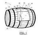
- FIG. 1is a partially sectioned perspective view of a portion of a barrel bladder system, according to an embodiment of the invention
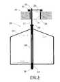
- FIG. 2is a partially sectioned perspective view of a portion of a barrel bladder system, according to an embodiment of the invention
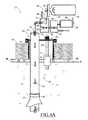
- FIG. 3is a partially sectioned side view of a portion of a barrel bladder system, according to an embodiment of the invention.
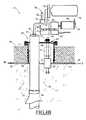
- FIG. 4Ais a partially sectioned side view of a portion of a barrel bladder system, according to an embodiment of the invention.
- FIG. 4Bis a partially sectioned side view of a portion of a barrel bladder system, according to an embodiment of the invention.
- FIG. 4Cis a partially sectioned side view of a portion of a barrel bladder system, according to an embodiment of the invention.
- FIG. 4Dis a partially sectioned side view of a portion of a barrel bladder system, according to an embodiment of the invention.
- FIG. 5is a top view of a portion of a barrel bladder system, according to an embodiment of the invention.
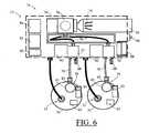
- FIG. 6is a top view of a portion of a barrel bladder system, according to an embodiment of the invention.
- FIG. 7is a schematic view of a networked barrel bladder system, according to an embodiment of the invention.
- FIG. 8is a schematic view of a networked barrel bladder system, according to an embodiment of the invention.
- the present inventionprovides a bladder system and apparatus, able to reduce a head space in a wooden container of a fermented beverage, especially wine.
- the bladder system and apparatuscontinuously protects the aging wine contained in a wooden barrel from the harmful effects of oxidation at the air-to-fluid interface and also compensates for the loss or leakage of wine from its container, referred to as “ullage,” which is often attributable to evaporation, leakage or wine sampling losses.
- FIGS. 1 through 8show preferred embodiments and features of the bladder system and apparatus 15 , or simply referred to herein as the bladder system.
- the bladder systemis configured to monitor and react to the quantity of a fermented beverage, which can generally be referred to herein as a beverage 17 , such as wine, cider, juice or spirit, as stored within a container that is preferably made primarily of wood, such as a barrel 18 .
- the bladder systemincludes a barrel service mechanism 20 , as shown inserted into the barrel, in FIGS. 1 and 2 .
- the barrel service mechanismhas an inflation stem 21 connected to an inflatable bladder 22 .
- the barrel 18can be any conventional container, typically formed of wood staves 13 held together with metal bands or “hoops” 14 , as employed for storing wine, or any other beverage 17 , such as beer, cider, juice, brandy, whiskey, or more generally spirits, or any other beverage that may be fermented, as known to those skilled in the crafting of such beverages.
- Standard wine barrelsare coopered with staves of white oak, and can generally contain approximately sixty gallons.
- the bladder 22 and inflation stem 21are insert-able into the barrel when the bladder is uninflated, as shown in FIG. 1 .
- the uninflated bladder and attached inflation stemcan be inserted through and anchored within a bung opening 26 of the barrel.
- the barrelcan be rolled to place the bung opening proximate to an upper container surface 27 of the barrel, which is the high point of the barrel when the barrel is placed on its side, as shown in FIGS. 1 and 2 .
- a “head-space” 28is typically found in the barrel, as shown in the barrel's cutaway area of FIGS. 1 and 2 .
- the head spaceis a pocket of air or gas, formed above the beverage within the barrel, also proximate to the high point of the barrel.
- the inflation stem 21is received into an inflation stem housing 29 , which includes a bung anchor 31 .
- the bung anchoracts as stopper, and is inserted into the bung opening 26 of the barrel, typically with a threaded attachment, to anchor within and seal the bung opening, while allowing the passage of elements of the barrel service mechanism 20 , as needed and further disclosed herein.
- the inflation stem housing 29 of the barrel service mechanism 20also holds a liquid level sensor 33 .
- the liquid level sensorcan be any conventional sensor with the ability to detect the level of a liquid, and output, modify or modulate a signal, based upon the sensed level.
- the liquid level sensormay be mounted within the head space 28 of the barrel 18 , as preferred, or it may be substantially external to the barrel and detect the liquid level 48 through the container, as with ultrasonic pulses.
- the liquid level sensormay be analog or digital in nature, and may simply be a normally open, as preferred, or a normally closed float switch. Float switches are well known in technologies requiring liquid level sensing.
- a standard, electro-mechanical analog float switchwhich maintains an open circuit in its normal operational mode is preferred, and may be coupled with a temperature sensor or any other sensor desired, such as dissolved oxygen and dissolved carbon dioxide, as options.
- a solid state fluid level sensorsuch as an optical level sensor can be utilized as the liquid level sensor, as discussed further herein.
- the inflation stem 21preferably anchored vertically within the inflation stem housing 29 , includes an upper stem end 41 and a lower stem end 42 , as shown in FIG. 4A , with an inflation port 43 located proximate to the upper stem end, and a bladder port 44 , which is located proximate to the lower stem end.
- the inflation stemis manufactured from a stainless steel alloy, or some such material that will not corrode or impart any taste or flavor to the beverage 17 within the barrel 18 .
- the liquid level sensor 33is able to detect a liquid level 48 , within the head-space 28 of the barrel. By sensing the liquid level, in “approximate” relation to the upper container surface 27 , a head height “H” is determined.
- the head height His herein defined as a vertical distance between the upper container surface proximate to the bung opening 26 , and the liquid level 48 , directly beneath the bung opening.
- FIGS. 4A , 4 B and 4 Dshow various head heights in different operational scenarios or modes, of the bladder system 15 .
- the head heightis reduced by filling the bladder 22 , which is inflatable by filling with an inflation gas 55 , which is stored in a gas tank 56 also referred to herein as a gas container.
- a gas valve 52opens as directed, when a signal to inflate the bladder is initiated by the liquid level sensor 33 . When the gas valve opens, the inflation gas is released from the gas tank, and routed to the inflation stem 21 of the bladder service mechanism 20 .
- the liquid level sensor 33includes a float 63 that travels along a reed 64 .
- the liquid level sensoracts as a switch, to close a gas valve circuit 66 , when the liquid level 48 falls below a preset, low or fill level “F,” as shown in FIG. 4A .
- the gas valve circuitis most preferably a low voltage control circuit, with the gas valve normally closed in the non-energized state, or equivalently acting sensor and circuit, as are known to those skilled in industrial system control and design.
- the float 63 of the liquid level sensor 33lowers from a target position 53 to a fill position 54 , as shown in FIG. 4A , which results in the sending of an “open valve” signal to the gas valve 52 , preferably by initiating closing of the gas valve circuit 66 to open the gas valve, as discussed above.
- This open valve signaloccurs when the head height H is greater than a predetermined low level, referred to herein as an inflate or fill level “F”.
- the fill levelis the low end of the normally fluctuating liquid level 48 of the wine or beverage, within the barrel.
- the bladder 22is inflated while it is submerged within the barrel 18 during action of the pressurized feed of the inflation gas 55 , as metered through the gas valve 52 .
- the forced introduction of the inflation gas into the bladderinflates the bladder to displace the beverage 17 into the volume of the head-space 28 , by raising the liquid level 48 within the barrel, and so reducing the head height H.
- the bladderis most preferably a thin walled rubber, or other semi-elastomeric, synthetic and substantially non-permeable and rubber-like material, such as a poly propylene, and shaped as shown in FIG. 1 or alternatively in FIG. 3 .
- the materialis selected to undergo repeated stress on inflation, and also to exhibit little or no diffusion, and be unreactive with the beverage 17 contacted within the barrel, or with the inflation gas.
- a preferred size of the bladderis approximately ten percent of the volume of the barrel.
- a preferred bladderis approximately three to ten gallons in volume, with a most preferred size of five gallons.
- the bladderis affixed to the inflation stem 21 .
- the bladderis slipped over the distal part of the stainless steel shaft of the inflation stem housing, like a sleeve, and will slide under an anchor ring 58 , preferably with an airtight, silicon seal.
- a bottom anchor 59is preferably employed, also with an airtight seal.
- the bottom anchorattaches snugly, preferably with a threaded connection, to secure the bottom end of the bladder to the inflation stem.
- the inflation stemincludes a gas slot 60 , along the inflation stem within the bladder.
- the inflation gas 55can be any gas that is preferably inert and will not add off-flavoring or react with the beverage 17 stored within the barrel 18 .
- a most preferred inflation gasis carbon dioxide, or alternatively argon or nitrogen.
- the bladder system 15is shown in FIG. 4B with the float 63 of the liquid level sensor 33 in its target position 53 and the liquid level 48 in a targeted, or “target” position “T,” with the head height H, minimized to be as near as practicable to the upper container surface 27 .
- the gas valve circuitreopens to shut off the filling of the bladder and maintain the liquid level at the targeted position T, shown in FIG. 4B , with excess gas in the head-space 28 relieved from the inflation stem housing 29 , through bung relief port 65 , shown in FIGS. 4A through 4D , 5 and 6 .
- the bladder system 15preferably includes critical alarm monitoring, to verify proper operation of the system.
- the float 63 of the liquid level sensor 33may rise from the target position 53 to a high alarm position 57 .
- the floatalso rises to the high alarm position, preferably causing a high alarm circuit 67 to close.
- Activation of the high alarm circuitserves to open a relief port 68 , which is preferably a component of the gas valve 52 .
- the high alarm circuitis most preferably a low voltage control circuit, as is known to those skilled in industrial system control and design.
- the bladder systemresponds to the release of the inflation gas 55 from the relief port, as shown in FIG. 4C , the bladder deflates, and the float lowers along the reed, back to the T position as shown in FIG. 4B , and the high alarm circuit reopens to shut off the release of inflation gas through the relief port, and continue to maintain the liquid level at the targeted position T.
- the closing of the high alarm circuitcan also serve to activate an alarm, to notify the operator of a possible overfill of the barrel 18 , or overinflation problem with the bladder 22 .
- the reed 64 of the liquid level sensor 33extends below the fill level “F,” to a low alarm level “LA.”
- the closing of the low alarm circuitcan also serve to activate an alarm, to notify the operator of the under-fill of the barrel 18 , or a near maximum inflation of the bladder.
- a key component of the bladder system 15is a control module 70 , as shown in FIG. 5 .
- the control moduleconnects and communicates directly with the barrel service mechanism 20 , which is inserted into each barrel 18 , as discussed above.
- the control moduleregulates the feed of the inflation gas 55 into the inflation stem 21 , as a result of the electronic feedback from the liquid level sensor 33 .
- the control modulepreferably includes the ability to communicate to a local server 74 , for tracking operational activity of the control module, and to incorporate a multiple of control modules into a control network 75 , as detailed later, herein.
- the control module 70includes the gas valve 52 for controlling the flow of the inflation gas 55 into the inflation stem 21 of the barrel service mechanism 20 .
- the gas valveis activated in response from changes in the liquid level 48 , as sensed by the liquid level sensor 33 .
- the inflation gas 55is supplied to the actuator valve from the gas container 56 , which is preferably a tank of the inflation gas, pressurized or alternatively liquified within the container.
- a central, large gas containermay serve any multiple of barrels 18 , simply manifolded though a gas pressure regulator 76 , and routed through a gas line 78 to the gas valve 52 of each control module 70 , as needed for inflation of the individual bladders 22 .
- Smaller, easily managed gas containersare preferred, which minimize hazards of handling pressurized gas tanks or containers, especially during transport.
- the gas container 56may be embodied by a single tank of supply inflation gas dedicated to each barrel 18 , in a single barrel set-up 71 , as shown in FIG. 5 , or the gas container may be coupled in a duplex barrel set-up 72 , as most preferred, with a dedicated gas infeed line 78 , to the gas valve 52 of each control module 70 , as shown in FIGS. 6 and 7 .
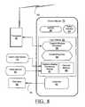
- the control module's operation of the gas valveis preferably accomplished with a logic module 81 and a controller 82 , as shown schematically in FIG. 8 .
- the controllercan be any electro-mechanical valve controller, such as a solenoid, and the logic module preferably includes an onboard memory 83 , interfaced with a control microprocessor 84 , the design and operation of which are well known to those in the field of remote controlled firmware for small valves.
- the onboard memory storageis preferably a conventional “flash” type of memory device that stores the computing instruction or the controller, along with and any collected operation data, for transmission to the local server 74 .
- a digital-to-analog conversion module 87can also be included within the logic module, to actuate and monitor the controller with instructions based upon digital signals.
- the digital-to-analog conversion modulecan be utilized for any needed conversions of digital instruction to analog outputs from the control module, or the analog-to-digital conversion of analog information input to the control module.
- control module 70is powered with low voltage circuitry, which can be supplied by a low voltage electrical supply connection, or more preferably by a battery 88 .
- the batteryis most preferably continually recharged, to prevent interruptions in power to the control module.
- a transceiver 85is included within or in close proximity to the control module 70 .
- the solid state transceiverpreferably receives direction from a transmit-receive processor 86 , as shown in FIG. 8 , which directs the timing format of sent and received sequences of fixed-length digital data to a router 91 , which is a component of the local server 74 , and preferably able to receive and transmit to the individual control modules through each transceiver.
- the local server 74has the ability to oversee and direct the operation of several control modules 70 by communications through the router.
- Each transmit-receive processor 86can perform conventional data-logging functions to regularly transmit the operational status or sensor inputs, as temporally stored in the onboard memory 83 of the logic module 81 .
- the transceiver 85 of the control module 70can communicate with the router 91 by a wired connection, or a wireless connection, as preferred.
- the transceivermay emit or receive a communication signal 93 , to or from the router.
- the communication signalis preferably a local-area type of transmission, with a unique digital identification to any specific control module that it emanates from, or is directed to.
- the frequency band of the communication signalmay be any conventional communication band, such as infrared, radio, or alternatively in higher frequencies, as employed by BluetoothTM transceivers.
- Conventional “polling” routinesmay be employed by the local server 74 to verify communication linkage to and proper operation of the control modules. The local server thereby is alerted when any of the control modules fail to respond, such as in a board failure or loss of power.
- a status indicator 94such as a conventional LED can be employed, as shown in FIGS. 4A through 4D , 5 , 6 and 8 , to visually display the operational condition of the bladder system, as sensed by the control module, such as “nominal operation,” or “alarm.” Audible alarms can also be included with or instead of the LED as a status indicator.
- additional or other sensors 95may be incorporated within or external to the barrel service mechanism 20 for each control module 70 , if desired. This allows the barrel service mechanism to act as a sensor platform. Examples of additional sensors include ambient temperature, beverage temperature, sugar or ‘Brix’ level metering, pH, gas composition, or any other conventional chemistry probes, as desired to be telemetered in conjunction with the operation of the bladder system 15 .
- the inflation stem housing 29can be separate from the barrel service mechanism or the additional sensors 95 .
- the inflation stem 21 and attached bladder 22could be inserted into a second bung opening at the side, the bottom, or at the head of the barrel 22 , if convenient or desired.
- calculation of and tracking of the volume of wine 17 lost from the barrel 18 as a function of the pressure of the inflation gas 55 with the bladder 22is performed, or alternatively approximated by the time of solenoid valve opening and feed pressure of inflation gas 55 .
- This additional sensed informationcan be included in the information processed by the logic module 81 and stored in the onboard memory 83 of the control module, and telemetered to the router 91 and local server 74 , with aid of the transmit-receive processor 86 , thus creating an ‘intelligent’ barrel sensing and control network.
- any realistic multiple of control modules 70may be included in the control network 75 , designated as “A,” along with “B,” and up to “n” control modules, all networked into the local server 74 through the router 91 .
- the local serverincludes a “local data archive” 96 , that collects operational data, as polled from the networked control modules, over time.
- this datamay be shared or augmented with “additional local data archives” 106 , as collected by additional servers 107 , each overseeing the operation of control modules in other bladder systems 15 .
- a central, “remote data archive” 116could be stored at a remote user's PC 117 , to collect, compile and analyze the operational data from several bladder systems 15 .
- This data and interface with a multiple of networked bladder systemsforms the overarching control network 80 , which can be employed to optimize the operation of the individual bladder systems.
- control network 80can include any additional parameter collected by the individual control modules 70 in connection to their barrel service mechanisms 20 , or related sensors as previously described, herein.
- the bladder system 15 of the present inventioncan be used by any winery that employs wooden barrels to store or age the wine 17 in the winemaking processes.
- the bladder systemcontinuously protects the aging wine from the harmful effects of oxidation at the air-to-fluid interface, within the barrel 22 , resulting from the conventional ullage processes.
- “Ullage”can be defined as the amount of wine lost from a barrel through natural evaporation, leakage or sampling.
- the overall quality of the wine 17is improved with use of the bladder system 15 , by curtailing oxidation of the wine 17 at the head-space 28 , as compared to conventional, manual “topping-up protocols,” which depend on the manual inspection and filling of each barrel 18 in a preset schedule.
- This common protocolinherently causes an extended length of time to lapse between successive re-fillings of the barrel, and therefore allows an ever-enlarging surface area at the air-fluid level within the barrel, due to ullage.
- Oxidationwhich is well known to be the principal spoiler of wine, is significantly reduced during barrel aging using the bladder system 15 , by maintaining a near constant air-fluid level over time.
- top-up wineBarrels of wine manually topped-up using standard techniques are usually filled with inferior quality wine called “top-up wine.”
- This top-up wineis usually pooled from excess sources and it often comprises different varietals of wine, and is usually stored in small stainless steel containers limiting appropriate aging.
- wine that is stored and aged using the bladder systemrequires very minimal, if any, dilution with different and inferior wine.
- the bladder system 15provides for the safe and accurate quantifying of ullage, eliminating or greatly reducing the need for topping-off, making the process more efficient and safer to synchronize the consolidation of wines from the same or similar lots, if desired. Additionally, the bladder system reduces the personnel required and associated potentials for injury in traditional topping up methods, while improving the overall quality of wines produced with aid of the system.
Landscapes
- Engineering & Computer Science (AREA)
- Organic Chemistry (AREA)
- Chemical & Material Sciences (AREA)
- Health & Medical Sciences (AREA)
- Bioinformatics & Cheminformatics (AREA)
- Life Sciences & Earth Sciences (AREA)
- General Health & Medical Sciences (AREA)
- Wood Science & Technology (AREA)
- General Engineering & Computer Science (AREA)
- Biochemistry (AREA)
- Genetics & Genomics (AREA)
- Food Science & Technology (AREA)
- Zoology (AREA)
- Mechanical Engineering (AREA)
- General Chemical & Material Sciences (AREA)
- Chemical Kinetics & Catalysis (AREA)
- Dermatology (AREA)
- Medicinal Chemistry (AREA)
- Nuclear Medicine, Radiotherapy & Molecular Imaging (AREA)
- Pharmacology & Pharmacy (AREA)
- Animal Behavior & Ethology (AREA)
- Public Health (AREA)
- Veterinary Medicine (AREA)
- Devices For Dispensing Beverages (AREA)
Abstract
Description
Claims (11)
Priority Applications (6)
| Application Number | Priority Date | Filing Date | Title |
|---|---|---|---|
| US12/589,927US8365758B2 (en) | 2009-10-30 | 2009-10-30 | Beverage barrel bladder system and apparatus |
| EP10860115.4AEP2588389A2 (en) | 2009-10-30 | 2010-10-29 | Beverage barrel bladder system and apparatus |
| CA2785972ACA2785972A1 (en) | 2009-10-30 | 2010-10-29 | Beverage barrel bladder system and apparatus |
| PCT/US2010/002870WO2013028144A2 (en) | 2009-10-30 | 2010-10-29 | Beverage barrel bladder system and apparatus |
| AU2010366389AAU2010366389B2 (en) | 2009-10-30 | 2010-10-29 | Beverage barrel bladder system and apparatus |
| MX2012004895AMX2012004895A (en) | 2009-10-30 | 2010-10-29 | Beverage barrel bladder system for reducing the head space in the beverage container. |
Applications Claiming Priority (1)
| Application Number | Priority Date | Filing Date | Title |
|---|---|---|---|
| US12/589,927US8365758B2 (en) | 2009-10-30 | 2009-10-30 | Beverage barrel bladder system and apparatus |
Publications (2)
| Publication Number | Publication Date |
|---|---|
| US20110101010A1 US20110101010A1 (en) | 2011-05-05 |
| US8365758B2true US8365758B2 (en) | 2013-02-05 |
Family
ID=43924302
Family Applications (1)
| Application Number | Title | Priority Date | Filing Date |
|---|---|---|---|
| US12/589,927Active - Reinstated2031-01-07US8365758B2 (en) | 2009-10-30 | 2009-10-30 | Beverage barrel bladder system and apparatus |
Country Status (5)
| Country | Link |
|---|---|
| US (1) | US8365758B2 (en) |
| EP (1) | EP2588389A2 (en) |
| AU (1) | AU2010366389B2 (en) |
| MX (1) | MX2012004895A (en) |
| WO (1) | WO2013028144A2 (en) |
Cited By (6)
| Publication number | Priority date | Publication date | Assignee | Title |
|---|---|---|---|---|
| US20120125930A1 (en)* | 2010-11-18 | 2012-05-24 | Michelle Arney | Fluid preservation system and method for use |
| US20150337249A1 (en)* | 2014-05-22 | 2015-11-26 | Wensi Peng | Device for Topping Up Alcoholic Beverages in Vessels |
| US9605991B2 (en) | 2014-04-01 | 2017-03-28 | Xerox Corporation | Floating mechanical level sensor |
| US11378569B2 (en) | 2020-08-31 | 2022-07-05 | Simple Labs, Inc. | Smoke taint sensing device |
| FR3142463A1 (en)* | 2022-11-29 | 2024-05-31 | Bellot | Connected drain for wine tank |
| IT202200025344A1 (en)* | 2022-12-12 | 2024-06-12 | Alessandro Bonomo | ALCOHOL-BASED FOOD LIQUID MONITORING SYSTEM |
Families Citing this family (25)
| Publication number | Priority date | Publication date | Assignee | Title |
|---|---|---|---|---|
| US20130317764A1 (en)* | 2012-05-24 | 2013-11-28 | Kentucky State University | Apparatus and method for monitoring a liquid product in a sealed vessel |
| KR20140036669A (en)* | 2012-09-17 | 2014-03-26 | 한국전자통신연구원 | Apparatus and method for measuring aging environment |
| ITGE20130010A1 (en)* | 2013-01-24 | 2014-07-25 | Enosis Srl | DEVICE FOR PROTECTING A LIQUID FROM OXIDATION |
| US20140326143A1 (en)* | 2013-05-06 | 2014-11-06 | 16 MILE BREWING COMPANY Inc. | Imbrue keg infusion apparatus and system |
| US20150014340A1 (en)* | 2013-07-10 | 2015-01-15 | Erick Dalee Smith | Apparatus and method to limit slosh and ullage in a liquid container |
| US10203238B2 (en) | 2014-03-07 | 2019-02-12 | Barrelogix, Llc | Liquid detection apparatus |
| WO2015161043A1 (en)* | 2014-04-18 | 2015-10-22 | Miller Jr Robert A | High pressure enhanced structure technology |
| FR3032200B1 (en)* | 2015-02-02 | 2017-01-20 | Vatan-Vini | DEVICE FOR AIDING VINIFICATION AND / OR STORAGE OF WINE, ITS USE AND PROCESS FOR VINIFICATION OF RED WINE |
| US11384324B2 (en)* | 2015-02-24 | 2022-07-12 | Albrecht Holdings Llc | Reconditioned or infused fluid containers and related methods |
| ES2616151B1 (en)* | 2015-12-09 | 2017-12-12 | Universidad Europea Miguel De Cervantes, S.A. | Device for detecting the loss of liquid inside a barrel or similar container. |
| US20180079563A1 (en)* | 2016-09-16 | 2018-03-22 | Michael T. Georgacopoulos | Hybrid Barrel and Reusable System Therefor |
| USD894528S1 (en) | 2018-02-27 | 2020-09-01 | Edward Manuel | Footwear remover |
| WO2020041165A1 (en)* | 2018-08-21 | 2020-02-27 | Roth River, Inc. | Systems and methods for stored liquid monitoring |
| US12139695B2 (en) | 2018-09-03 | 2024-11-12 | Intellectual Property Pty Ltd | Method for conditioning wood barrels |
| US12421482B2 (en) | 2018-11-20 | 2025-09-23 | Watgrid, S.A. | Monitoring system for winemaking |
| US11899003B2 (en) | 2018-11-20 | 2024-02-13 | Watgrid, S.A. | Universal electronic bung system |
| US11187626B2 (en)* | 2018-11-20 | 2021-11-30 | Watgrid, S.A. | Fermentation monitoring system |
| IT201900002433A1 (en)* | 2019-02-20 | 2020-08-20 | Gilardi Daniela | DEVICE FOR THE STORAGE OF LIQUIDS |
| US20200354143A1 (en)* | 2019-05-07 | 2020-11-12 | Scott Houle | Inflatable bladder system for bulk liquid transport |
| CN114383413B (en)* | 2020-10-19 | 2024-06-04 | 江苏鑫浩新材料科技有限公司 | Side sealing device capable of automatically detecting pressure and belt sintering machine |
| US11248946B1 (en)* | 2021-02-09 | 2022-02-15 | Aloft Sensor Technologies LLC | Devices, systems, and methods for measuring fluid level using radio-frequency (RF) localization |
| US11898892B2 (en) | 2021-02-09 | 2024-02-13 | Aloft Sensor Technologies LLC | Devices, systems, and methods for measuring fluid level using radio-frequency (RF) localization |
| WO2023097394A1 (en)* | 2021-12-01 | 2023-06-08 | Barrelwise Technologies Ltd. | Method, apparatus and system for monitoring a plurality of barrels containing a beverage |
| WO2024242713A1 (en)* | 2023-05-19 | 2024-11-28 | Bit365 | Improved container assembly for aging a liquid |
| US12264303B1 (en)* | 2023-09-14 | 2025-04-01 | Theos Wd Distillery Llc | Cultivated alcohol aging device and method |
Citations (26)
| Publication number | Priority date | Publication date | Assignee | Title |
|---|---|---|---|---|
| US262773A (en) | 1882-08-15 | Appaeatus foe deawing liquors feom eegs | ||
| US447974A (en) | 1891-03-10 | Closing device for bottles | ||
| US534541A (en)* | 1895-02-19 | Faucet and attachments therefor | ||
| US713708A (en) | 1902-08-16 | 1902-11-18 | William G Spire | Stopper. |
| US3083098A (en)* | 1960-08-01 | 1963-03-26 | Edward W Sullivan | Method and means for aging alcoholic beverages |
| US3343701A (en) | 1965-07-14 | 1967-09-26 | Frank D Mahoney | Sealing and exhausting device for containers |
| US3744680A (en)* | 1971-12-20 | 1973-07-10 | V Salmonson | Gas control beer dispenser |
| US4211115A (en)* | 1979-03-08 | 1980-07-08 | Engebreth Roald N | Device for protecting wine against excessive exposure to air |
| US4456038A (en)* | 1981-03-25 | 1984-06-26 | Hennessy Industries, Inc. | Apparatus for pressurizing tires to a desired level |
| FR2587813A1 (en)* | 1985-09-25 | 1987-03-27 | Pernin Const Meca | Level-adjusting device for a liquid container |
| US4763803A (en) | 1986-01-20 | 1988-08-16 | Schneider Bernardus J J A | Stopper for a container such as a bottle, and a pump connectable thereto for extraction of gaseous medium from or pumping in thereof into the container |
| US5458165A (en) | 1994-10-19 | 1995-10-17 | Liebmann, Jr.; George W. | Gas actuator assembly |
| US5709558A (en)* | 1995-09-28 | 1998-01-20 | Endress + Hauser Gmbh + Co. | Electronics enclosure |
| US5947326A (en)* | 1997-11-12 | 1999-09-07 | Alasco Rubber & Plastics Corporation | Bung and stopper |
| US5976583A (en)* | 1998-06-24 | 1999-11-02 | Mastrocola; Edward P. | Apparatus and method for protecting wine aging in casks from exposure to air |
| US6183982B1 (en) | 1998-02-27 | 2001-02-06 | Ferm-Rite, Inc. | Fermentation bung device and method |
| US6312588B1 (en)* | 1998-11-09 | 2001-11-06 | Fantom Technologies Inc. | Water purifier |
| US6478178B2 (en) | 2001-03-08 | 2002-11-12 | Donald C. Montgomery | Fermentation lock for wine barrel |
| US20040010263A1 (en) | 1998-06-01 | 2004-01-15 | Kyphon Inc. | Expandable preformed structures for deployment in interior body regions |
| US6910498B2 (en)* | 2000-10-30 | 2005-06-28 | Michael L. Cazden | Liquid level controller |
| US20060032548A1 (en)* | 2004-08-10 | 2006-02-16 | Ranco Incorporated Of Delaware | Integral in tank vent construction for pressure based level monitors |
| US7051901B2 (en)* | 2003-03-19 | 2006-05-30 | Hickert Paul R | Air barrier device for protecting liquid fluids in opened containers |
| US7204930B2 (en)* | 2004-07-16 | 2007-04-17 | Skagit Farmers Supply | Water purification system and method |
| US20070209706A1 (en)* | 2006-03-09 | 2007-09-13 | Ching-Chuan Wu | Hydraulic device |
| US20090139584A1 (en)* | 2004-12-01 | 2009-06-04 | Torrent Trading Ltd. | Valve Assembly With Overfill Protection Device And Capacitive Liquid Level Gauge |
| US7878214B1 (en)* | 2006-08-10 | 2011-02-01 | Jansen's Aircraft Systems Controls, Inc. | Ullage pressure regulator |
Family Cites Families (7)
| Publication number | Priority date | Publication date | Assignee | Title |
|---|---|---|---|---|
| US713706A (en)* | 1902-05-05 | 1902-11-18 | Otis Elevator Co | Safety device for elevators. |
| FR990554A (en)* | 1949-07-12 | 1951-09-24 | Method and installation for the extraction of liquid by means of pressurized fluid | |
| ES285004Y (en)* | 1982-11-05 | 1986-04-16 | Miller Franz Geo | ARRANGEMENT OF STORAGE CONTAINER FOR BEVERAGES TO BE PRESERVED WITH EXCLUSION OF AIR, SUCH AS VI-NO, MUSTO SWEET STERILIZED OR SIMILAR |
| AUPR390301A0 (en)* | 2001-03-22 | 2001-04-12 | Guszlovan, Jim | Wine barrel filling apparatus |
| AUPR700001A0 (en)* | 2001-08-15 | 2001-09-06 | Flextank Pty Ltd | Submerged ullage and dispenser pouches for wine barrels |
| DE10215690B4 (en)* | 2002-04-10 | 2004-05-27 | Franz Stahl | Device for the preservative removal of a perishable liquid from a container with a removal opening arranged above the liquid |
| US20090095776A1 (en)* | 2007-10-15 | 2009-04-16 | Peter Turner | Wine preservation system and method |
- 2009
- 2009-10-30USUS12/589,927patent/US8365758B2/enactiveActive - Reinstated
- 2010
- 2010-10-29WOPCT/US2010/002870patent/WO2013028144A2/enactiveApplication Filing
- 2010-10-29EPEP10860115.4Apatent/EP2588389A2/ennot_activeWithdrawn
- 2010-10-29MXMX2012004895Apatent/MX2012004895A/enactiveIP Right Grant
- 2010-10-29AUAU2010366389Apatent/AU2010366389B2/ennot_activeCeased
Patent Citations (28)
| Publication number | Priority date | Publication date | Assignee | Title |
|---|---|---|---|---|
| US262773A (en) | 1882-08-15 | Appaeatus foe deawing liquors feom eegs | ||
| US447974A (en) | 1891-03-10 | Closing device for bottles | ||
| US534541A (en)* | 1895-02-19 | Faucet and attachments therefor | ||
| US713708A (en) | 1902-08-16 | 1902-11-18 | William G Spire | Stopper. |
| US3083098A (en)* | 1960-08-01 | 1963-03-26 | Edward W Sullivan | Method and means for aging alcoholic beverages |
| US3343701A (en) | 1965-07-14 | 1967-09-26 | Frank D Mahoney | Sealing and exhausting device for containers |
| US3744680A (en)* | 1971-12-20 | 1973-07-10 | V Salmonson | Gas control beer dispenser |
| US4211115A (en)* | 1979-03-08 | 1980-07-08 | Engebreth Roald N | Device for protecting wine against excessive exposure to air |
| US4456038A (en)* | 1981-03-25 | 1984-06-26 | Hennessy Industries, Inc. | Apparatus for pressurizing tires to a desired level |
| FR2587813A1 (en)* | 1985-09-25 | 1987-03-27 | Pernin Const Meca | Level-adjusting device for a liquid container |
| US4763803A (en) | 1986-01-20 | 1988-08-16 | Schneider Bernardus J J A | Stopper for a container such as a bottle, and a pump connectable thereto for extraction of gaseous medium from or pumping in thereof into the container |
| US4911314A (en) | 1986-01-20 | 1990-03-27 | Schneider Bernardus J J A | Stopper for a container such as a bottle, and a pump connectable thereto for extraction of gaseous medium from or pumping in thereof into the container |
| US4911314B1 (en) | 1986-01-20 | 1992-03-24 | J J A Schneider Bernardus | |
| US5458165A (en) | 1994-10-19 | 1995-10-17 | Liebmann, Jr.; George W. | Gas actuator assembly |
| US5709558A (en)* | 1995-09-28 | 1998-01-20 | Endress + Hauser Gmbh + Co. | Electronics enclosure |
| US5947326A (en)* | 1997-11-12 | 1999-09-07 | Alasco Rubber & Plastics Corporation | Bung and stopper |
| US6183982B1 (en) | 1998-02-27 | 2001-02-06 | Ferm-Rite, Inc. | Fermentation bung device and method |
| US20040010263A1 (en) | 1998-06-01 | 2004-01-15 | Kyphon Inc. | Expandable preformed structures for deployment in interior body regions |
| US5976583A (en)* | 1998-06-24 | 1999-11-02 | Mastrocola; Edward P. | Apparatus and method for protecting wine aging in casks from exposure to air |
| US6312588B1 (en)* | 1998-11-09 | 2001-11-06 | Fantom Technologies Inc. | Water purifier |
| US6910498B2 (en)* | 2000-10-30 | 2005-06-28 | Michael L. Cazden | Liquid level controller |
| US6478178B2 (en) | 2001-03-08 | 2002-11-12 | Donald C. Montgomery | Fermentation lock for wine barrel |
| US7051901B2 (en)* | 2003-03-19 | 2006-05-30 | Hickert Paul R | Air barrier device for protecting liquid fluids in opened containers |
| US7204930B2 (en)* | 2004-07-16 | 2007-04-17 | Skagit Farmers Supply | Water purification system and method |
| US20060032548A1 (en)* | 2004-08-10 | 2006-02-16 | Ranco Incorporated Of Delaware | Integral in tank vent construction for pressure based level monitors |
| US20090139584A1 (en)* | 2004-12-01 | 2009-06-04 | Torrent Trading Ltd. | Valve Assembly With Overfill Protection Device And Capacitive Liquid Level Gauge |
| US20070209706A1 (en)* | 2006-03-09 | 2007-09-13 | Ching-Chuan Wu | Hydraulic device |
| US7878214B1 (en)* | 2006-08-10 | 2011-02-01 | Jansen's Aircraft Systems Controls, Inc. | Ullage pressure regulator |
Non-Patent Citations (1)
| Title |
|---|
| Delback, FR2587813 Patent Translate Machine Translation, Mar. 27, 1987, European Patent Office.* |
Cited By (10)
| Publication number | Priority date | Publication date | Assignee | Title |
|---|---|---|---|---|
| US20120125930A1 (en)* | 2010-11-18 | 2012-05-24 | Michelle Arney | Fluid preservation system and method for use |
| US8820551B2 (en)* | 2010-11-18 | 2014-09-02 | Smart Assets, Inc. | Expandable fluid preservation system and method for use |
| US9238533B2 (en)* | 2010-11-18 | 2016-01-19 | Smart Assets, Inc. | Expandable fluid preservation system and method for use |
| US9533797B2 (en) | 2010-11-18 | 2017-01-03 | Michelle Arney | Expandable fluid preservation system and method for use |
| US9834338B2 (en) | 2010-11-18 | 2017-12-05 | Smart Assets, Inc. | Expandable fluid preservation system and method for use |
| US9605991B2 (en) | 2014-04-01 | 2017-03-28 | Xerox Corporation | Floating mechanical level sensor |
| US20150337249A1 (en)* | 2014-05-22 | 2015-11-26 | Wensi Peng | Device for Topping Up Alcoholic Beverages in Vessels |
| US11378569B2 (en) | 2020-08-31 | 2022-07-05 | Simple Labs, Inc. | Smoke taint sensing device |
| FR3142463A1 (en)* | 2022-11-29 | 2024-05-31 | Bellot | Connected drain for wine tank |
| IT202200025344A1 (en)* | 2022-12-12 | 2024-06-12 | Alessandro Bonomo | ALCOHOL-BASED FOOD LIQUID MONITORING SYSTEM |
Also Published As
| Publication number | Publication date |
|---|---|
| WO2013028144A3 (en) | 2013-04-18 |
| AU2010366389A1 (en) | 2013-03-21 |
| AU2010366389B2 (en) | 2016-03-17 |
| WO2013028144A2 (en) | 2013-02-28 |
| US20110101010A1 (en) | 2011-05-05 |
| MX2012004895A (en) | 2013-08-08 |
| EP2588389A2 (en) | 2013-05-08 |
Similar Documents
| Publication | Publication Date | Title |
|---|---|---|
| US8365758B2 (en) | Beverage barrel bladder system and apparatus | |
| US20190291062A1 (en) | Systems and methods for carbonating liquid in a container and detecting carbon dioxide levels in a carbon dioxide source | |
| US7395949B2 (en) | Volumetric displacement dispenser | |
| US8757439B2 (en) | Beverage packaging | |
| US9714163B2 (en) | Container for storing a liquid foodstuff and dispensing it under pressure | |
| US20140262899A1 (en) | Recharging cap for beverage container | |
| US20030080142A1 (en) | Methods and apparatus for maintaining equilibrium pressure in a container | |
| US20060163290A1 (en) | Volumetric displacement dispenser | |
| US12281288B2 (en) | Systems, devices, and methods for introducing additives to a pressurised vessel | |
| CN101605469A (en) | Recarbonation device | |
| CN108473294A (en) | Beverage withdrawal device for bubble drink | |
| CA2785972A1 (en) | Beverage barrel bladder system and apparatus | |
| US20040005394A1 (en) | Process and apparatus for aging rum | |
| CN204642675U (en) | Fresh-keeping fat | |
| US9630827B2 (en) | Dispenser device of carbonated beverages | |
| JP2005512588A (en) | Method and apparatus for producing an alcohol-containing sparkling beverage | |
| JP4243907B2 (en) | Beverage pouring method and apparatus | |
| AU2011100514A4 (en) | Beverage Packaging | |
| US20130319969A1 (en) | Method and Apparatus for Portable Beverage Containers that Preserve and Re-Carbonate Beverages Exposed to Atmosphere Air | |
| BR102024001461A2 (en) | SYSTEM AND METHOD FOR GENERATION OF CARBON DIOXIDE APPLIED TO BEER TAPERS | |
| BG2578U1 (en) | UNIVERSAL JUDGES ON NATURAL GAS | |
| AU2013219176A1 (en) | Beverage packaging | |
| BG2914U1 (en) | Natural carbonated beverages machine | |
| BG67118B1 (en) | Multi-purpose vessel for natural carbonation of beverages |
Legal Events
| Date | Code | Title | Description |
|---|---|---|---|
| AS | Assignment | Owner name:ANGLES' SHARE INNOVATIONS, LLC, WASHINGTON Free format text:ASSIGNMENT OF ASSIGNORS INTEREST;ASSIGNOR:MAIOCCO, MARK A., MR.;REEL/FRAME:027349/0266 Effective date:20111128 | |
| STCF | Information on status: patent grant | Free format text:PATENTED CASE | |
| FPAY | Fee payment | Year of fee payment:4 | |
| FEPP | Fee payment procedure | Free format text:MAINTENANCE FEE REMINDER MAILED (ORIGINAL EVENT CODE: REM.); ENTITY STATUS OF PATENT OWNER: SMALL ENTITY | |
| LAPS | Lapse for failure to pay maintenance fees | Free format text:PATENT EXPIRED FOR FAILURE TO PAY MAINTENANCE FEES (ORIGINAL EVENT CODE: EXP.); ENTITY STATUS OF PATENT OWNER: SMALL ENTITY | |
| STCH | Information on status: patent discontinuation | Free format text:PATENT EXPIRED DUE TO NONPAYMENT OF MAINTENANCE FEES UNDER 37 CFR 1.362 | |
| FP | Lapsed due to failure to pay maintenance fee | Effective date:20210205 | |
| PRDP | Patent reinstated due to the acceptance of a late maintenance fee | Effective date:20210415 | |
| FEPP | Fee payment procedure | Free format text:PETITION RELATED TO MAINTENANCE FEES GRANTED (ORIGINAL EVENT CODE: PMFG); ENTITY STATUS OF PATENT OWNER: SMALL ENTITY Free format text:SURCHARGE, PETITION TO ACCEPT PYMT AFTER EXP, UNINTENTIONAL. (ORIGINAL EVENT CODE: M2558); ENTITY STATUS OF PATENT OWNER: SMALL ENTITY Free format text:PETITION RELATED TO MAINTENANCE FEES FILED (ORIGINAL EVENT CODE: PMFP); ENTITY STATUS OF PATENT OWNER: SMALL ENTITY | |
| MAFP | Maintenance fee payment | Free format text:PAYMENT OF MAINTENANCE FEE, 8TH YR, SMALL ENTITY (ORIGINAL EVENT CODE: M2552); ENTITY STATUS OF PATENT OWNER: SMALL ENTITY Year of fee payment:8 | |
| STCF | Information on status: patent grant | Free format text:PATENTED CASE | |
| AS | Assignment | Owner name:INGENIOUS BARREL INNOVATIONS, LLC, WASHINGTON Free format text:ASSIGNMENT OF ASSIGNORS INTEREST;ASSIGNOR:ANGELS' SHARE INNOVATIONS, LLC;REEL/FRAME:058936/0378 Effective date:20220207 | |
| FEPP | Fee payment procedure | Free format text:MAINTENANCE FEE REMINDER MAILED (ORIGINAL EVENT CODE: REM.); ENTITY STATUS OF PATENT OWNER: SMALL ENTITY | |
| FEPP | Fee payment procedure | Free format text:11.5 YR SURCHARGE- LATE PMT W/IN 6 MO, SMALL ENTITY (ORIGINAL EVENT CODE: M2556); ENTITY STATUS OF PATENT OWNER: SMALL ENTITY | |
| MAFP | Maintenance fee payment | Free format text:PAYMENT OF MAINTENANCE FEE, 12TH YR, SMALL ENTITY (ORIGINAL EVENT CODE: M2553); ENTITY STATUS OF PATENT OWNER: SMALL ENTITY Year of fee payment:12 |