US8365700B2 - Shaping a fuel charge in a combustion chamber with multiple drivers and/or ionization control - Google Patents
Shaping a fuel charge in a combustion chamber with multiple drivers and/or ionization controlDownload PDFInfo
- Publication number
- US8365700B2 US8365700B2US12/841,149US84114910AUS8365700B2US 8365700 B2US8365700 B2US 8365700B2US 84114910 AUS84114910 AUS 84114910AUS 8365700 B2US8365700 B2US 8365700B2
- Authority
- US
- United States
- Prior art keywords
- fuel
- valve
- combustion chamber
- air
- force generator
- Prior art date
- Legal status (The legal status is an assumption and is not a legal conclusion. Google has not performed a legal analysis and makes no representation as to the accuracy of the status listed.)
- Expired - Fee Related, expires
Links
- 239000000446fuelSubstances0.000titleclaimsabstractdescription365
- 238000002485combustion reactionMethods0.000titleclaimsabstractdescription183
- 238000007493shaping processMethods0.000titledescription4
- 238000002347injectionMethods0.000claimsabstractdescription36
- 239000007924injectionSubstances0.000claimsabstractdescription36
- 239000000203mixtureSubstances0.000claimsdescription49
- 239000007800oxidant agentSubstances0.000claimsdescription48
- 230000001590oxidative effectEffects0.000claimsdescription48
- 238000000034methodMethods0.000claimsdescription27
- 239000003302ferromagnetic materialSubstances0.000claimsdescription11
- 230000033001locomotionEffects0.000claimsdescription11
- 238000004891communicationMethods0.000claimsdescription6
- 238000005259measurementMethods0.000claimsdescription6
- 230000001939inductive effectEffects0.000claimsdescription2
- 230000004048modificationEffects0.000claimsdescription2
- 238000012986modificationMethods0.000claimsdescription2
- 238000011022operating instructionMethods0.000claims4
- 210000002381plasmaAnatomy0.000description46
- 238000004519manufacturing processMethods0.000description15
- 230000008901benefitEffects0.000description14
- 239000012212insulatorSubstances0.000description12
- 150000002500ionsChemical class0.000description11
- 238000012384transportation and deliveryMethods0.000description9
- 239000000463materialSubstances0.000description8
- 238000007747platingMethods0.000description8
- 239000003989dielectric materialSubstances0.000description7
- 238000010586diagramMethods0.000description6
- 230000001965increasing effectEffects0.000description6
- 230000035515penetrationEffects0.000description6
- 230000003628erosive effectEffects0.000description5
- 239000003502gasolineSubstances0.000description5
- 238000012544monitoring processMethods0.000description5
- 238000012546transferMethods0.000description5
- 239000002826coolantSubstances0.000description4
- 239000002283diesel fuelSubstances0.000description4
- 238000009826distributionMethods0.000description4
- 238000009760electrical discharge machiningMethods0.000description4
- 239000000835fiberSubstances0.000description4
- 230000002441reversible effectEffects0.000description4
- 238000003860storageMethods0.000description4
- 239000000126substanceSubstances0.000description4
- LFQSCWFLJHTTHZ-UHFFFAOYSA-NEthanolChemical compoundCCOLFQSCWFLJHTTHZ-UHFFFAOYSA-N0.000description3
- OKKJLVBELUTLKV-UHFFFAOYSA-NMethanolChemical compoundOCOKKJLVBELUTLKV-UHFFFAOYSA-N0.000description3
- 230000003044adaptive effectEffects0.000description3
- 230000000712assemblyEffects0.000description3
- 238000000429assemblyMethods0.000description3
- 230000004888barrier functionEffects0.000description3
- 239000003054catalystSubstances0.000description3
- 230000006835compressionEffects0.000description3
- 238000007906compressionMethods0.000description3
- 239000004020conductorSubstances0.000description3
- 239000007789gasSubstances0.000description3
- 238000002309gasificationMethods0.000description3
- 239000007788liquidSubstances0.000description3
- 230000003647oxidationEffects0.000description3
- 238000007254oxidation reactionMethods0.000description3
- 230000001681protective effectEffects0.000description3
- 239000013598vectorSubstances0.000description3
- XLYOFNOQVPJJNP-UHFFFAOYSA-NwaterSubstancesOXLYOFNOQVPJJNP-UHFFFAOYSA-N0.000description3
- IJGRMHOSHXDMSA-UHFFFAOYSA-NAtomic nitrogenChemical compoundN#NIJGRMHOSHXDMSA-UHFFFAOYSA-N0.000description2
- KFZMGEQAYNKOFK-UHFFFAOYSA-NIsopropanolChemical compoundCC(C)OKFZMGEQAYNKOFK-UHFFFAOYSA-N0.000description2
- LRHPLDYGYMQRHN-UHFFFAOYSA-NN-ButanolChemical compoundCCCCOLRHPLDYGYMQRHN-UHFFFAOYSA-N0.000description2
- 230000001133accelerationEffects0.000description2
- 150000001298alcoholsChemical class0.000description2
- 230000015572biosynthetic processEffects0.000description2
- 230000008859changeEffects0.000description2
- 238000012512characterization methodMethods0.000description2
- 230000007797corrosionEffects0.000description2
- 238000005260corrosionMethods0.000description2
- 238000001704evaporationMethods0.000description2
- 230000008020evaporationEffects0.000description2
- 230000006698inductionEffects0.000description2
- 230000000977initiatory effectEffects0.000description2
- 230000005291magnetic effectEffects0.000description2
- VNWKTOKETHGBQD-UHFFFAOYSA-NmethaneChemical compoundCVNWKTOKETHGBQD-UHFFFAOYSA-N0.000description2
- 230000008569processEffects0.000description2
- 229910052594sapphireInorganic materials0.000description2
- 239000010980sapphireSubstances0.000description2
- 230000035939shockEffects0.000description2
- 238000001228spectrumMethods0.000description2
- 239000011029spinelSubstances0.000description2
- 229910052596spinelInorganic materials0.000description2
- 239000007921spraySubstances0.000description2
- 229910017109AlONInorganic materials0.000description1
- CIWBSHSKHKDKBQ-JLAZNSOCSA-NAscorbic acidChemical compoundOC[C@H](O)[C@H]1OC(=O)C(O)=C1OCIWBSHSKHKDKBQ-JLAZNSOCSA-N0.000description1
- 229910052582BNInorganic materials0.000description1
- PZNSFCLAULLKQX-UHFFFAOYSA-NBoron nitrideChemical compoundN#BPZNSFCLAULLKQX-UHFFFAOYSA-N0.000description1
- UFHFLCQGNIYNRP-UHFFFAOYSA-NHydrogenChemical compound[H][H]UFHFLCQGNIYNRP-UHFFFAOYSA-N0.000description1
- FYYHWMGAXLPEAU-UHFFFAOYSA-NMagnesiumChemical compound[Mg]FYYHWMGAXLPEAU-UHFFFAOYSA-N0.000description1
- 239000000654additiveSubstances0.000description1
- 239000000443aerosolSubstances0.000description1
- 230000004075alterationEffects0.000description1
- XAGFODPZIPBFFR-UHFFFAOYSA-NaluminiumChemical compound[Al]XAGFODPZIPBFFR-UHFFFAOYSA-N0.000description1
- 229910052782aluminiumInorganic materials0.000description1
- 238000013459approachMethods0.000description1
- 238000003491arrayMethods0.000description1
- 230000005540biological transmissionEffects0.000description1
- 239000001273butaneSubstances0.000description1
- 230000015556catabolic processEffects0.000description1
- 239000000919ceramicSubstances0.000description1
- 238000006243chemical reactionMethods0.000description1
- 239000002131composite materialSubstances0.000description1
- 238000009833condensationMethods0.000description1
- 230000005494condensationEffects0.000description1
- 239000000356contaminantSubstances0.000description1
- 238000001816coolingMethods0.000description1
- 238000005336crackingMethods0.000description1
- 238000005520cutting processMethods0.000description1
- 238000013500data storageMethods0.000description1
- 238000006731degradation reactionMethods0.000description1
- 230000000593degrading effectEffects0.000description1
- 230000001419dependent effectEffects0.000description1
- 238000000151depositionMethods0.000description1
- 238000013461designMethods0.000description1
- 239000010432diamondSubstances0.000description1
- 229910003460diamondInorganic materials0.000description1
- 239000006185dispersionSubstances0.000description1
- 238000010292electrical insulationMethods0.000description1
- 230000005611electricityEffects0.000description1
- LWSYSCQGRROTHV-UHFFFAOYSA-Nethane;propaneChemical compoundCC.CCCLWSYSCQGRROTHV-UHFFFAOYSA-N0.000description1
- 230000006870functionEffects0.000description1
- 238000010438heat treatmentMethods0.000description1
- 239000008240homogeneous mixtureSubstances0.000description1
- 239000001257hydrogenSubstances0.000description1
- 229910052739hydrogenInorganic materials0.000description1
- 230000003116impacting effectEffects0.000description1
- 238000002955isolationMethods0.000description1
- 150000002605large moleculesChemical class0.000description1
- 230000001050lubricating effectEffects0.000description1
- 229920002521macromoleculePolymers0.000description1
- 229910052749magnesiumInorganic materials0.000description1
- 239000011777magnesiumSubstances0.000description1
- 230000005415magnetizationEffects0.000description1
- IJDNQMDRQITEOD-UHFFFAOYSA-Nn-butaneChemical compoundCCCCIJDNQMDRQITEOD-UHFFFAOYSA-N0.000description1
- OFBQJSOFQDEBGM-UHFFFAOYSA-Nn-pentaneNatural productsCCCCCOFBQJSOFQDEBGM-UHFFFAOYSA-N0.000description1
- 229910052757nitrogenInorganic materials0.000description1
- 230000003287optical effectEffects0.000description1
- 239000013307optical fiberSubstances0.000description1
- 238000005457optimizationMethods0.000description1
- 239000012188paraffin waxSubstances0.000description1
- 230000036961partial effectEffects0.000description1
- 239000003208petroleumSubstances0.000description1
- -1platingSubstances0.000description1
- 238000002360preparation methodMethods0.000description1
- 238000012545processingMethods0.000description1
- 239000010453quartzSubstances0.000description1
- 230000005855radiationEffects0.000description1
- 239000000376reactantSubstances0.000description1
- 230000002829reductive effectEffects0.000description1
- 230000001172regenerating effectEffects0.000description1
- 230000008929regenerationEffects0.000description1
- 238000011069regeneration methodMethods0.000description1
- 230000004044responseEffects0.000description1
- 239000004065semiconductorSubstances0.000description1
- VYPSYNLAJGMNEJ-UHFFFAOYSA-Nsilicon dioxideInorganic materialsO=[Si]=OVYPSYNLAJGMNEJ-UHFFFAOYSA-N0.000description1
- 239000004449solid propellantSubstances0.000description1
- 230000002459sustained effectEffects0.000description1
- 239000012780transparent materialSubstances0.000description1
- 238000002604ultrasonographyMethods0.000description1
- 238000009834vaporizationMethods0.000description1
- 230000008016vaporizationEffects0.000description1
- 230000035899viabilityEffects0.000description1
Images


Classifications
- F—MECHANICAL ENGINEERING; LIGHTING; HEATING; WEAPONS; BLASTING
- F02—COMBUSTION ENGINES; HOT-GAS OR COMBUSTION-PRODUCT ENGINE PLANTS
- F02M—SUPPLYING COMBUSTION ENGINES IN GENERAL WITH COMBUSTIBLE MIXTURES OR CONSTITUENTS THEREOF
- F02M57/00—Fuel-injectors combined or associated with other devices
- F02M57/06—Fuel-injectors combined or associated with other devices the devices being sparking plugs
- F—MECHANICAL ENGINEERING; LIGHTING; HEATING; WEAPONS; BLASTING
- F02—COMBUSTION ENGINES; HOT-GAS OR COMBUSTION-PRODUCT ENGINE PLANTS
- F02D—CONTROLLING COMBUSTION ENGINES
- F02D35/00—Controlling engines, dependent on conditions exterior or interior to engines, not otherwise provided for
- F02D35/02—Controlling engines, dependent on conditions exterior or interior to engines, not otherwise provided for on interior conditions
- F02D35/021—Controlling engines, dependent on conditions exterior or interior to engines, not otherwise provided for on interior conditions using an ionic current sensor
- F—MECHANICAL ENGINEERING; LIGHTING; HEATING; WEAPONS; BLASTING
- F02—COMBUSTION ENGINES; HOT-GAS OR COMBUSTION-PRODUCT ENGINE PLANTS
- F02D—CONTROLLING COMBUSTION ENGINES
- F02D37/00—Non-electrical conjoint control of two or more functions of engines, not otherwise provided for
- F02D37/02—Non-electrical conjoint control of two or more functions of engines, not otherwise provided for one of the functions being ignition
- F—MECHANICAL ENGINEERING; LIGHTING; HEATING; WEAPONS; BLASTING
- F02—COMBUSTION ENGINES; HOT-GAS OR COMBUSTION-PRODUCT ENGINE PLANTS
- F02M—SUPPLYING COMBUSTION ENGINES IN GENERAL WITH COMBUSTIBLE MIXTURES OR CONSTITUENTS THEREOF
- F02M51/00—Fuel-injection apparatus characterised by being operated electrically
- F02M51/06—Injectors peculiar thereto with means directly operating the valve needle
- F02M51/061—Injectors peculiar thereto with means directly operating the valve needle using electromagnetic operating means
- F02M51/0625—Injectors peculiar thereto with means directly operating the valve needle using electromagnetic operating means characterised by arrangement of mobile armatures
- F02M51/0664—Injectors peculiar thereto with means directly operating the valve needle using electromagnetic operating means characterised by arrangement of mobile armatures having a cylindrically or partly cylindrically shaped armature, e.g. entering the winding; having a plate-shaped or undulated armature entering the winding
- F02M51/0671—Injectors peculiar thereto with means directly operating the valve needle using electromagnetic operating means characterised by arrangement of mobile armatures having a cylindrically or partly cylindrically shaped armature, e.g. entering the winding; having a plate-shaped or undulated armature entering the winding the armature having an elongated valve body attached thereto
- F—MECHANICAL ENGINEERING; LIGHTING; HEATING; WEAPONS; BLASTING
- F02—COMBUSTION ENGINES; HOT-GAS OR COMBUSTION-PRODUCT ENGINE PLANTS
- F02M—SUPPLYING COMBUSTION ENGINES IN GENERAL WITH COMBUSTIBLE MIXTURES OR CONSTITUENTS THEREOF
- F02M57/00—Fuel-injectors combined or associated with other devices
- F02M57/005—Fuel-injectors combined or associated with other devices the devices being sensors
- F—MECHANICAL ENGINEERING; LIGHTING; HEATING; WEAPONS; BLASTING
- F02—COMBUSTION ENGINES; HOT-GAS OR COMBUSTION-PRODUCT ENGINE PLANTS
- F02M—SUPPLYING COMBUSTION ENGINES IN GENERAL WITH COMBUSTIBLE MIXTURES OR CONSTITUENTS THEREOF
- F02M69/00—Low-pressure fuel-injection apparatus ; Apparatus with both continuous and intermittent injection; Apparatus injecting different types of fuel
- F02M69/04—Injectors peculiar thereto
- F02M69/041—Injectors peculiar thereto having vibrating means for atomizing the fuel, e.g. with sonic or ultrasonic vibrations
- F—MECHANICAL ENGINEERING; LIGHTING; HEATING; WEAPONS; BLASTING
- F02—COMBUSTION ENGINES; HOT-GAS OR COMBUSTION-PRODUCT ENGINE PLANTS
- F02P—IGNITION, OTHER THAN COMPRESSION IGNITION, FOR INTERNAL-COMBUSTION ENGINES; TESTING OF IGNITION TIMING IN COMPRESSION-IGNITION ENGINES
- F02P15/00—Electric spark ignition having characteristics not provided for in, or of interest apart from, groups F02P1/00 - F02P13/00 and combined with layout of ignition circuits
- F02P15/006—Ignition installations combined with other systems, e.g. fuel injection
- F—MECHANICAL ENGINEERING; LIGHTING; HEATING; WEAPONS; BLASTING
- F02—COMBUSTION ENGINES; HOT-GAS OR COMBUSTION-PRODUCT ENGINE PLANTS
- F02D—CONTROLLING COMBUSTION ENGINES
- F02D41/00—Electrical control of supply of combustible mixture or its constituents
- F02D41/30—Controlling fuel injection
- F02D41/38—Controlling fuel injection of the high pressure type
- F02D41/3809—Common rail control systems
- F02D41/3836—Controlling the fuel pressure
- F—MECHANICAL ENGINEERING; LIGHTING; HEATING; WEAPONS; BLASTING
- F02—COMBUSTION ENGINES; HOT-GAS OR COMBUSTION-PRODUCT ENGINE PLANTS
- F02D—CONTROLLING COMBUSTION ENGINES
- F02D41/00—Electrical control of supply of combustible mixture or its constituents
- F02D41/30—Controlling fuel injection
- F02D41/38—Controlling fuel injection of the high pressure type
- F02D41/40—Controlling fuel injection of the high pressure type with means for controlling injection timing or duration
- F02D41/402—Multiple injections
Definitions
- the following disclosurerelates generally to fuel injectors and igniters and associated components for injecting and igniting various fuels in an internal combustion engine.
- gasolineis mixed with air to form a homogeneous mixture that enters a combustion chamber of an engine during throttled conditions of an intake cycle.
- the mixture of gasoline (fuel) and airis then compressed to near top dead center (TDC) conditions and ignited by a spark, such as a spark generated by a spark plug or a fuel igniter.
- TDCtop dead center
- the multiple valvesIn addition to multiple valves restricting the available space for fuel injectors and spark plugs, the multiple valves often supply large heat loads to an engine head due to a greater heat gain during heat transfer from the combustion chamber to the engine head and related components. There may be further heat generated in the engine head by cam friction, valve springs, valve lifters, and other components, particularly in high-speed operations of the valves.
- Spark ignition of an engineis a high voltage but low energy ionization of a mixture of air and fuel (such as 0.05 to 0.15 joules for normally aspirated engines equipped with spark plugs that operate with compression ratios of 12:1 or less).
- the required voltageshould also increase. For example, smaller ratios of fuel to air to provide a lean mixture, a wider spark gap to achieve sustained ignition, supercharging or turbocharging or other conditions may change the ionization potential or ambient pressure in a spark gap, and hence require an increase in the applied voltage.
- FIG. 1is a schematic view of a suitable injector/igniter.
- FIG. 2is a cross-sectional side view of a suitable injector/igniter.
- FIGS. 3A-3Care various side views of suitable ignition systems.
- FIGS. 4A-4Dillustrate layered burst patterns of fuel injected into a combustion chamber.
- FIG. 5is a flow diagram illustrating a routine for injecting fuel into a combustion chamber.
- FIGS. 6A-6Billustrate layered burst patterns of fuel injected into a combustion chamber.
- FIG. 7is a flow diagram illustrating a routine for controlling the ionization of an air-fuel mixture during ignition within a combustion chamber.
- FIG. 8is a flow diagram illustrating a routine for operating a fuel ignition device in a combustion engine.
- the fuel injectorincludes ignition components, such as electrodes, and act as a combination injector-igniter.
- the fuel injectorincludes two or more drivers or force generators configured to impart two or more driving forces to a fuel-dispensing device (e.g., a valve) in order to modify the shape or other characteristics of the fuel when injecting the fuel into a combustion chamber of an engine.
- a fuel-dispensing devicee.g., a valve
- the fuel injectormay include an electromagnetic driver that causes a valve to open and a piezoelectric driver that causes the open valve to modulate in the opening. Such modulation may provide certain shapes and/or surface area to volume ratios of the fuel entering surplus oxidant, such as fuel aerosols, dispersions, or fogs of varying fuel densities, among other things.
- fuel injection and/or ignition devicesare integrated with internal combustion engines, as well as associated systems, assemblies, components, and methods.
- some embodiments described hereinare directed to adaptable fuel injectors/igniters that optimize or improve the injection and/or combustion of various fuels based on combustion chamber conditions, among other benefits.
- controllers associated with fuel injectors and/or ignition systemsmeasure certain characteristics of a combustion chamber and modify operations of the fuel injectors and/or ignition systems accordingly. For example, the controllers may measure the ionization of an air-fuel mixture within a combustion chamber and modify the operation of the fuel injector and/or the fuel igniter based on the measurements. In some cases, the controllers modify the shape or characteristics of injected fuel. In some cases, the controllers modify the operation of the fuel igniters, such as by reversing a polarity of a voltage applied to electrodes of the fuel igniter, among other things. Such modification of the injected fuel and/or the operation of various devices may provide improved or faster ignition of air-fuel mixtures or may reduce or prevent erosion of the electrodes and other internal components, among other benefits.
- FIGS. 1-8Certain details are set forth in the following description and in FIGS. 1-8 to provide a thorough understanding of various embodiments of the disclosure. However, other details describing well-known structures and systems often associated with internal combustion engines, injectors, igniters, controllers, and/or other aspects of combustion systems are not set forth below to avoid unnecessarily obscuring the description of various embodiments of the disclosure. Thus, it will be appreciated that several of the details set forth below are provided to describe the following embodiments in a manner sufficient to enable a person skilled in the relevant art to make and use the disclosed embodiments. Several of the details and advantages described herein, however, may not be necessary to practice certain embodiments of the disclosure.
- FIG. 1is a schematic view of a suitable integrated injector/igniter 110 configured in accordance with various embodiments of this disclosure.
- the injector 110may inject various different fuels into a combustion chamber 104 , such as a combustion chamber within a combustion engine. Further, the injector 104 may adaptively adjust the pattern and/or frequency of the fuel injections or bursts based on combustion properties, parameters, and/or conditions within the combustion chamber 104 .
- the injector 110may optimize or improve characteristics (e.g., shape of fuel) of injected fuel to achieve benefits such as rapid ignition, to reduce the time for completion of combustion, or to reduce the total distance of fuel travel to achieve complete combustion, or to reduce heat losses from combustion events.
- characteristicse.g., shape of fuel
- the injector 110may also ignite the injected fuel using one or more integrated ignition devices and components that are configured to ignite the injected fuel.
- the injector 110can be utilized to convert conventional internal combustion engines for use with many different fuels.
- the injector 110includes a body 112 having a middle portion 116 extending between a base portion 114 and a nozzle portion 118 .
- the nozzle portion 118extends at least partially through a port in an engine head 107 to position an end portion 119 of the nozzle portion 118 at an interface with the combustion chamber 104 .
- the injector 110includes a passage or channel 123 extending through the body 112 from the base portion 114 to the nozzle portion 118 .
- the channel 123is configured to allow fuel to flow through the body 112 .
- the channel 123is also configured to allow other components, such as an actuator 122 , to pass through the body 112 , as well as instrumentation components and/or energy source components of the injector 110 .
- the actuator 122is a cable or rod that has a first end portion that is operatively coupled to a flow control device or valve 120 carried by the end portion 119 of the nozzle portion 118 .
- the flow valve 120is positioned proximate to the interface with the combustion chamber 104 .
- the injector 110can include more than one flow valve as shown in U.S. patent application entitled Fuel Injector Actuator Assemblies and Associated Methods of Use and Manufacture, filed concurrently on Jul. 21, 2010, as well as one or more check valves positioned proximate to the combustion chamber 104 , as well as at other locations on the body 112 .
- the actuator 122includes a second end portion operatively coupled to a one or more drivers 124 , 130 , 140 .
- the second end portioncan further be coupled to a controller or processor 126 .
- the controller 126 and/or the drivers 124 , 130 , 140are configured to cause the valve 120 to inject fuel into the combustion chamber 104 via the actuator 122 .
- the actuator 122driven by one or more of the drivers, causes the flow valve 120 move outwardly (e.g., toward the combustion chamber 104 ) to meter and control injection of the fuel.
- the actuator 122driven by one or more of the drivers, causes the flow valve 120 to move inwardly (e.g., away from the combustion chamber 104 ) to meter and control injection of the fuel.
- the drivers 124 , 130 , 140are responsive to instructions received from the controller 126 as well as other components providing instruction.
- Various different driversmay impart forces to the actuator 122 , such as acoustic drivers, electromagnetic drivers, piezoelectric drivers, and so on, to achieve a desired frequency, pattern, and/or shape of injected fuel bursts.
- the fuel injectorincludes two or more drivers used to impart driving forces on the actuator 122 .
- a first driver 124may tension the actuator 122 to retain the flow valve 120 in a closed or seated position, or may relax the actuator 122 to allow the flow valve 120 to inject fuel, and vice versa.
- a second driver 130 or 140may close, vibrate, pulsate, or modulate the actuator 122 in the open position.
- the fuel injector 110may employ two or more driving forces on the valve 120 to achieve a desired frequency, pattern, and/or shape of injected fuel bursts.
- the fuel injector 110includes one or more integrated sensing and/or transmitting components to detect combustion chamber properties and conditions.
- the actuator 122may be formed from fiber optic cables, from insulated transducers integrated within a rod or cable, or can include other sensors to detect and communicate combustion chamber data.
- the fuel injector 110may include other sensors or monitoring instrumentation (not shown) located at various positions on or in the fuel injector 110 .
- the body 112may include optical fibers integrated into the material of the body 112 , or the material of the body 112 may be used to communicate combustion data to one or more controllers, such as controller 126 .
- the flow valve 120may be configured to measure data or carry sensors in order to transmit combustion data to one or more controllers associated with the fuel injector 110 .
- the datamay be transmitted via wireless, wired, optical or other transmission devices and protocols.
- Such feedbackenables extremely rapid and adaptive adjustments for optimization of fuel injection factors and characteristics including, for example, fuel delivery pressure, fuel injection initiation timing, fuel injection durations for production of multiple layered or stratified charges, the timing of one, multiple or continuous plasma ignitions or capacitive discharges, preventing erosion of components, and so on.
- the controller 126may include components capable and configured to receive the data measured by the sensors, store the data received from the sensors, store other data associated with fuel injection or operations of a fuel injector or fuel igniter, processors, communication components, and so on.
- the controllermay include various microprocessors, memory components, communication components, and other components used to adjust and/or modify various operations.
- These components, modules, or systems described herein, such as components of the controller 126 and/or the drivers 126 , 130 , 140may comprise software, firmware, hardware, or any combination(s) of software, firmware, or hardware suitable for the purposes described herein, including wireless communication from remote areas of operation to a central command and control location.
- the softwaremay be executed by a general-purpose computer, such as a computer associated with an ignition system or vehicle utilizing an ignition system.
- a general-purpose computersuch as a computer associated with an ignition system or vehicle utilizing an ignition system.
- aspects of the systemcan be practiced with other communications, data processing, or computer system configurations.
- aspects of the systemcan be embodied in a special purpose computer or data processor that is specifically programmed, configured, or constructed to perform one or more of the computer-executable instructions explained in detail herein.
- Data structures described hereinmay comprise computer files, variables, programming arrays, programming structures, or any electronic information storage schemes or methods, or any combinations thereof, suitable for the purposes described herein.
- Data and other informationmay be stored or distributed on computer-readable media, including magnetically or optically readable computer discs, hard-wired or preprogrammed chips (e.g., EEPROM semiconductor chips), nanotechnology memory, biological memory, or other data storage media.
- computer-readable mediaincluding magnetically or optically readable computer discs, hard-wired or preprogrammed chips (e.g., EEPROM semiconductor chips), nanotechnology memory, biological memory, or other data storage media.
- the fuel injector 110includes an ignition and flow adjusting device or cover 121 carried by the end portion 119 , adjacent to the engine head 107 .
- the cover 121at least partially encloses or surrounds the flow valve 120 .
- the cover 121may also be configured to protect certain components of the injector 110 , such as sensors or other monitoring components.
- the cover 121may also act as a catalyst, catalyst carrier and/or first electrode for ignition of the injected fuels.
- the cover 121may be configured to affect the shape, pattern, and/or phase of the injected fuel.
- the flow valve 120is configured to affect these properties of the injected fuel, and may include one or more electrodes used for ignition of the injected fuels.
- the cover 121 and/or the flow valve 120can be configured to create sudden gasification of the fuel flowing past these components.
- the cover 121 and/or the flow valve 120can include surfaces having sharp edges, catalysts, or other features that produce gas or vapor from the rapidly entering liquid fuel or mixture of liquid and solid fuel.
- the acceleration and/or frequency of the flow valve 120 actuationcan also suddenly gasify the injected fuel. In operation, sudden gasification causes the vapor or gas emitted from the nozzle portion 118 to rapidly and completely combust.
- the sudden gasificationmay be used in various combinations with super heating liquid fuels and plasmas or acoustical impetus of projected fuel bursts.
- the movement of the flow valve 12such as modulated movement due to multiple driving forces, induces the plasma projection to beneficially affect the shape and/or pattern of the injected fuel.
- the body 112is made from one or more dielectric materials 117 suitable to enable high energy ignition of injected fuels to combust different fuels, including unrefined fuels or low energy density fuels. These dielectric materials 117 may provide sufficient electrical insulation from high voltages used in the production, isolation, and/or delivery of spark or plasma for ignition.
- the body 112is made from a single dielectric material 117 .
- the body 112is made from two or more dielectric materials.
- the middle portion 116may be made from a first dielectric material having a first dielectric strength
- the nozzle portion 118may be made from a dielectric material having a second dielectric strength that is greater than the first dielectric strength. With a relatively strong second dielectric strength, the second dielectric material may protect the fuel injector 110 from thermal and mechanical shock, fouling, voltage tracking, and so on.
- the fuel injector 110is coupled to a power or high voltage source to generate an ignition event and combust injected fuels.
- a first electrodecan be coupled to the power source (e.g., a voltage generation source such as a capacitance discharge, induction, or piezoelectric system) via one or more conductors extending through the fuel injector 110 . Regions of the nozzle portion 118 , the flow valve 120 , and/or the cover 121 may operate as a first electrode to generate an ignition event with a corresponding second electrode at or integrated into the engine head 107 .
- Example ignition eventsinclude generating sparks, plasmas, compression ignition operations, high energy capacitance discharges, extended induction sourced sparks, and/or direct current or high frequency plasmas, often in conjunction with the application of ultrasound to quickly induce, impel, and finish combustion.
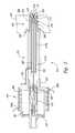
- FIG. 2is a cross-sectional side view of an example fuel injector 210 for use with an ignition system.
- the fuel injector 210includes several features that are generally similar in structure and function to the corresponding features of the injector 110 described above with reference to FIG. 1 .
- the injector 210includes a body 212 having a middle portion 216 extending between a base portion 214 and a nozzle portion 218 .
- the nozzle portion 218at least partially extends through an engine head 207 to position the end of the nozzle portion 218 at an interface with a combustion chamber 204 .
- the body 212includes a channel 263 extending through a portion thereof to allow fuel to flow through the injector 210 . Other components can also pass through the channel 263 .
- the injector 210further includes an actuator such as an assembly including 224 , 260 and 222 that is operatively coupled to a controller or processor 226 .
- the actuator rod or cable component 222is also coupled to a valve or clamp member 260 .
- the actuator 222extends through the channel 263 from a driver 224 in the base portion 214 to a flow valve 220 in the nozzle portion 218 .
- the actuator 222can be a cable or rod assembly including, for example, fiber optics, electrical signal fibers, and/or acoustic communication fibers along with wireless transducer nodes.
- the actuator 222is configured to cause the flow valve 220 to rapidly introduce multiple fuel bursts into the combustion chamber 204 .
- the actuator 222can also detect and/or transmit combustion properties to the controller 226 .
- the actuator 222retains the flow valve 220 in a closed position seated against a corresponding valve seat 272 .
- the base portion 214includes two or more force generators 261 , or drivers (shown schematically).
- the force generators 261may be an electromagnetic force generator, a piezoelectric force generator, a combination of an electromagnetic and piezoelectric force generator, or other suitable types of force generators including pneumatic and hydraulic types and corresponding combinations and permutations.
- the force generators 261are configured to produce driving forces that move the drivers 224 .
- the drivers 224contact the clamp member 260 to move the clamp member 260 along with the actuator 222 .
- the force generator 261can produce a force that acts on the drivers 224 to pull the clamp member 260 and tension the actuator 222 .
- the tensioned actuator 222retains the flow valve 220 in the valve seat 272 in the closed position.
- the actuator 222is relaxed thereby allowing the flow valve 220 to introduce fuel into the combustion chamber 204 .
- the force generators 261may produce a second force that causes the actuator 222 to move the flow valve 220 , such as by modulating the flow valve's movements at high frequencies.
- a first force generatormay impart a force to open the valve
- a second force generatormay impart forces to vibrate the valve open and closed or modulate the actuator when the valve is open.
- the nozzle portion within 218may include components that facilitate the actuation and positioning of the flow valve 220 .
- the flow valve 220can be made from a first ferromagnetic material or otherwise incorporate a first ferromagnetic material (e.g., via plating a portion of the flow valve 220 ).
- the nozzle portion within 218such as 270 or 272 can carry a corresponding second ferromagnetic material that is attracted to the first ferromagnetic material.
- the valve seat 272can incorporate the second ferromagnetic material. In this manner, these attractive components can help center the flow valve 220 in the valve seat 272 , as well as facilitate the rapid actuation of the flow valve 220 .
- the actuator 222passes through one or more centerline bearings (as further shown in Figures associated with concurrently filed application Fuel Injector Actuator Assemblies and Associated Methods of Use and Manufacture incorporated in its entirety by reference) to at least partially center the flow valve 220 in the valve seat 272 .
- Providing energy to actuate these attractive components of the injector 210may expedite the closing of the flow valve 220 , as well as provide increased closing forces acting on the flow valve 220 .
- Such a configurationcan enable extremely rapid opening and closing cycle times of the flow valve 220 , among other benefits.
- the application of voltage for initial spark or plasma formationmay ionize fuel passing near the surface of the valve seat 272 , which may also ionize a fuel and air mixture adjacent to the combustion chamber 204 to further expedite complete ignition and combustion.
- the base portion 214also includes heat transfer features 265 , such as heat transfer fins (e.g., helical fins).
- the base portion 214also includes a first fitting 262 a for introducing a suitable coolant including substances chosen for closed loop circulation to a heat rejection device such as a radiator, and substances such as fuel or another reactant that is consumed by the operation of the engine in which such coolants can flow around the heat transfer features 265 , as well as a second fitting 262 b to allow the coolant to exit the base portion 214 .
- a suitable coolantincluding substances chosen for closed loop circulation to a heat rejection device such as a radiator, and substances such as fuel or another reactant that is consumed by the operation of the engine in which such coolants can flow around the heat transfer features 265 , as well as a second fitting 262 b to allow the coolant to exit the base portion 214 .
- Such cooling of the fuel injectorcan at least partially prevent condensation and/or ice from forming when cold fuels are used, such as fuels
- the flow valve 220may carry instrumentation 276 for monitoring combustion chamber events.
- the flow valve 220may be a ball valve made from a generally transparent material, such as quartz or sapphire.
- the ball valve 220can carry the instrumentation 276 (e.g., sensors, transducers, and so on) inside the ball valve 220 .
- a cavityis formed in the ball valve 220 by cutting the ball valve 220 in a plane generally parallel with the face of the engine head 207 . In this manner, the ball valve 220 can be separated into a base portion 277 as well as a lens portion 278 .
- a cavitysuch as a conical cavity, can be formed in the base portion 277 to receive the instrumentation 276 .
- the lens portion 278can then be reattached (e.g., adhered) to the base portion 277 to retain the generally spherical shape of the ball valve 220 or be modified as desired to provide another type of lens.
- the ball valve 220positions the instrumentation 276 adjacent to the combustion chamber 204 interface. Accordingly, the instrumentation 276 can measure and communicate combustion data including, for example, pressure data, temperature data, motion data, and other data.
- the flow valve 220includes a treated face that protects the instrumentation 276 .
- a face of the flow valve 220may be protected by depositing a relatively inert substance, such as diamond like plating, sapphire, optically transparent hexagonal boron nitride, BN—AlN composite, aluminum oxynitride (AlON including Al 23 O 27 N 5 spinel), magnesium aliminate spinel, and/or other suitable protective materials.
- a relatively inert substancesuch as diamond like plating, sapphire, optically transparent hexagonal boron nitride, BN—AlN composite, aluminum oxynitride (AlON including Al 23 O 27 N 5 spinel), magnesium aliminate spinel, and/or other suitable protective materials.
- the body 212includes conductive plating 274 extending from the middle portion 216 to the nozzle portion 218 .
- the conductive plating 274is coupled to an electrical conductor or cable 264 .
- the cable 264can also be coupled to a power generator, such as a suitable piezoelectric, inductive, capacitive or high voltage circuit, for delivering energy to the injector 210 .
- the conductive plating 274is configured to deliver the energy to the nozzle portion 218 .
- the conductive plating 274 at the valve seat 272can act as a first electrode that generates an ignition event (e.g., spark or plasma) with corresponding conductive portions of the engine head 207 .
- an ignition evente.g., spark or plasma
- the nozzle portion 218includes an exterior sleeve 268 comprised of material that is resistant to spark erosion.
- the sleeve 268can also resist spark deposited material that is transferred to or from conductor 274 , 272 or the conductive plating 274 (e.g., the electrode zones of the nozzle portion 218 ).
- the nozzle portion 218may include a reinforced heat dam or protective portion 266 that is configured to at least partially protect the injector 210 from heat and other degrading combustion chamber factors.
- the protective portion 266can also include one or more transducers or sensors for measuring or monitoring combustion parameters, such as temperature, thermal and mechanical shock, and/or pressure events in the combustion chamber 204 .
- the middle portion 216 and the nozzle portion 218include a dielectric insulator, including a first insulator 217 a at least partially surrounding a second insulator 217 b .
- the second insulator 217 bextends from the middle portion 216 to the nozzle portion 218 . Accordingly, at least a segment of the second insulator 217 b is positioned adjacent to the combustion chamber 204 .
- the second insulator 217 bis of a greater dielectric strength than the first insulator 217 a . In this manner, the second insulator 217 b can be configured to withstand the harsh combustion conditions proximate to the combustion chamber 204 .
- the injector 210includes an insulator made from a single material.
- the second insulator 217 b in the nozzle portion 218is spaced apart from the combustion chamber 204 .
- the injector 210can form plasma of ionized oxidant such as air in the space 270 before a fuel injection event.
- This plasma projection of ionized aircan accelerate the combustion of fuel that enters the plasma.
- the plasma projectioncan affect the shape of the rapidly combusting fuel according to predetermined combustion chamber characteristics.
- the injector 210can also ionize components of the fuel, or ionize mixtures of fuel components and oxidant to produce high energy plasma, which can also affect or change the shape of the distribution pattern of the combusting fuel.
- fuel injectors 110 and 210include various components and devices, such as drivers, force generators, and so on, capable of imparting multiple driving forces on valves and other fuel dispensing devices in order to create and/or modify various fuel shapes or patterns.
- the fuel injectors 110 and 210also include various components and devices, such as controllers, capable of measuring parameters and other data associated with combustion events within combustion chambers and modifying operations of fuel injectors and fuel igniters based on the conditions within ignition systems.
- controllerscapable of measuring parameters and other data associated with combustion events within combustion chambers and modifying operations of fuel injectors and fuel igniters based on the conditions within ignition systems.
- FIG. 3Ais a side view illustrating a suitable ignition environment for an internal combustion system 300 having a fuel injector 310 .
- a combustion chamber 302is formed between a head portion containing the fuel injector 310 and valves, a movable piston 301 and the inner surface of a cylinder 303 .
- other environmentsmay implement the fuel injector 310 , such as environments with other types of combustion chambers and/or energy transferring devices, including various vanes, axial and radial piston expanders, numerous types of rotary combustion engines, and so on.
- the fuel injector 310may include several features that not only allow the injection and ignition of different fuels within the combustion chamber 302 , but also enable the injector 310 to adaptively inject and ignite these different fuels according to different combustion conditions or requirements.
- the injector 310may include one or more insulative materials configured to enable high-energy ignition of different fuel types, including unrefined fuels or low energy density fuels.
- the insulative materialsmay also withstand conditions required to combust different fuel types, including, for example, high voltage conditions, fatigue conditions, impact conditions, oxidation, erosion, and corrosion degradation.
- the injector 310may include instrumentation for sensing various properties of the combustion in the combustion chamber 302 (e.g., properties of the combustion process, the combustion chamber 302 , the engine 304 , and so on). In response to these sensed conditions, the injector 310 can adaptively optimize the fuel injection and ignition characteristics to achieve increased fuel efficiency and power production, as well as decrease noise, engine knock, heat losses and/or vibration to extend the engine and/or vehicle life, among other benefits.
- various properties of the combustion in the combustion chamber 302e.g., properties of the combustion process, the combustion chamber 302 , the engine 304 , and so on.
- the injector 310can adaptively optimize the fuel injection and ignition characteristics to achieve increased fuel efficiency and power production, as well as decrease noise, engine knock, heat losses and/or vibration to extend the engine and/or vehicle life, among other benefits.
- the injector 310may include actuating components to inject the fuel into the combustion chamber 302 to achieve specific flow or spray patterns 305 , as well as the phase, of the injected fuel.
- the injector 310may include one or more valves positioned proximate to the interface of the combustion chamber 302 .
- the actuating components, such as multiple drivers or force generators of the injector 310provide for precise, high frequency operation of the valve to control at least the following features: the timing of fuel injection initiation and completion, the frequency and duration of repeated fuel injections, the shape of injected fuel, the timing and selection of ignition events, and so on.
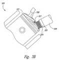
- FIG. 3Bshows partial views of characteristic engine block and head components and of injector 328 that operates as disclosed regarding embodiments with an appropriate fuel valve operator located in the upper insulated portion and that is electrically separated from the fuel flow control valve located very near the combustion chamber in which the stratified charge fuel injection pattern 326 is asymmetric as shown to accommodate the combustion chamber geometry shown.
- Such asymmetric fuel penetration patternsare preferably created by making appropriately larger fuel delivery passageways such as wider gaps in portions of slots shown in previous Figures to cause greater penetration of fuel entering the combustion chamber on appropriate fuel penetration rays of pattern 327 as shown to provide for optimized air utilization as a combustant and as an excess air insulator surrounding combustion to minimize heat losses to piston 324 , components of the head including intake or exhaust valve 322 , or the engine block including coolant in passages.
- FIG. 3Cis a schematic cross-sectional side view of a suitable ignition system 340 .
- the ignition system 340includes an integrated fuel injector/igniter 342 (e.g., an injector as described herein), a combustion chamber 346 , one or more unthrottled air flow valves 348 (identified individually as a first valve 348 a and a second valve 348 b ), and an energy transferring device, or piston 344 .
- the injector 342is configured to inject a layered or stratified charge of fuel 352 into the combustion chamber 346 .
- the ignition system 340is configured to inject and ignite the fuel 352 in an abundance or excess amount of an oxidant, such as air.
- the valves 348enable admission of oxidant such as air at ambient pressure or even a positive pressure in the combustion chamber 346 prior to the combustion event.
- oxidantsuch as air at ambient pressure or even a positive pressure in the combustion chamber 346 prior to the combustion event.
- the system 340can operate without throttling or otherwise impeding air flow into the combustion chamber such that a vacuum is not created by restricting air entering the combustion chamber 346 prior to igniting the fuel 352 .
- the excess oxidantforms an insulative barrier 350 adjacent to the surfaces of the combustion chamber (e.g., the cylinder walls, piston, engine head, and so on).
- the fuel injector 342injects the layered or stratified fuel 352 into the combustion chamber 346 in the presence of the excess oxidant. In some cases, the injection occurs when the piston 344 is at or past the top dead center position. In some cases, the fuel injector 342 injects the fuel 352 before the piston 344 reaches top dead center. Because the injector 342 is configured to adaptively inject the fuel including production of layered charges 352 as described herein, the fuel 352 is configured to rapidly ignite and completely combust in the presence of the insulative barrier 350 of the oxidant.
- the insulative zone of surplus oxidantserves as a type of barrier 350 that substantially shields the walls of the combustion chamber 346 from heat given off from the fuel 352 when the fuel 352 ignites, thereby avoiding heat loss to the walls of the combustion chamber 346 .
- the heat released by the rapid combustion of the fuel 352is converted into work to drive the piston 344 , rather than being transferred as a loss to the combustion chamber surfaces.
- FIGS. 4A-4Dillustrate several fuel burst patterns 405 (identified individually as 405 a - 405 d ) of injected fuel.
- the illustrated patterns 405are merely representative of various patterns and others are of course possible.
- the patterns 405have different shapes and configurations, these patterns 405 share the feature of having sequential fuel layers 407 .
- the individual layers 407 of the corresponding patterns 405provide the benefit of relatively large surface to volume ratios of the injected fuel.
- the large surface to volume ratiosprovide higher combustion rates of the fuel charges, and assist in insulating and accelerating complete combustion of the fuel charges.
- Fast and complete combustionprovides several advantages over slower burning fuel charges. For example, slower burning fuel charges require earlier ignition, cause significant heat losses to combustion chamber surfaces, and produce more backwork or output torque loss to overcome early pressure rise from the earlier ignition.
- systems, devices, and processes described hereinoptimize various combustion requirements for different fuel types. They include fuel injector/igniters having multiple actuators or drivers (e.g., piezoelectric, magnetic, hydraulic, and so on) that act together to inject certain fuel spray patterns or otherwise modulate the introduction of fuel into a combustion chamber of a combustion engine.
- actuators or driverse.g., piezoelectric, magnetic, hydraulic, and so on
- FIG. 5is a flow diagram illustrating a routine 500 for injecting fuel into a combustion chamber.
- a controllerassociated with fuel injector, receives feedback regarding ignition conditions in a combustion engine, such as conditions associated with a combustion chamber.
- the controllermay employ a number of different sensors to measure and receive information and data, such as sensors integrated into a fuel injector.
- the sensorsmay measure data associated with various parameters of ignition and combustion events within the combustion chamber, including pressure, temperature, fuel penetration into the oxidant inventory, subsequent fuel distribution patterns, motion of fuel distribution pattern, data associated with the ionization of an air-fuel mixture during a combustion of the mixture, rate of combustion of the mixtures produced, the ratio of fuel to air in a combusted mixture, penetration of the products of combustion into excess oxidant, patterns of the products of combustion, motion of the products of combustion and so on.
- the controllercauses an actuator of the fuel injector to impart a first driving force to a valve or other fuel-dispensing device of the fuel injector.
- the controllermay provide instructions including adjustment of the fuel injection pressure, adjustment of the beginning timing of each fuel injection, adjustment of the timing that each fuel injection event ends, adjustment of the time between each fuel injection event, and adjustments to a driver or force generator to impart certain driving forces that cause the fuel control valve at the combustion chamber interface such as 120 or 200 or various other configurations of copending applications (filed concurrently on Jul. 21, 2010 and incorporated by reference in the disclosure above) to open and close at certain frequencies in order to inject fuel into the combustion chamber with a desired shape or pattern, such as those shown in FIGS. 4A-4D .
- the controllercauses the actuator to impart a second driving force to the valve or other fuel-dispensing device of the fuel injector.
- the controllercauses an actuator within the fuel injector to impart the second driving force to vibrate the valve between open and closed positions or to further modify the shape or pattern of fuel during injection of the fuel.
- the controllermay modulate movement of the valve at high frequencies when the valve is open and allowing fuel to flow from the fuel injector and into the combustion chamber.
- the high frequency modulationgenerates fuel or charge shapes having various surface area to volume ratios.
- the controllerperforms the modulation based on the information received in step 510 , in order to provide suitable and effective fuel shapes with respect to conditions within a combustion chamber.
- Fuel injectors capable of performing routine 500may employ a variety of different drivers.
- the first drivermay be a piezoelectric valve driver and the second driver may be a piezoelectric driver.
- any drivers capable of imparting a resonant vibration to an actuator cablemay act as a second driver.
- a solenoidmay apply pulses using a pulse width modulation to an actuator cable in order to achieve modulation (similar to plucking a violin string).
- the pulse width modulationmay be adaptively adjusted to produce the desired shape and surface to volume ratios of the multiple fuel injections.
- the denser layer(s) and less dense layer(s) of fuelmay be generated by various multiples of the resonant vibration of the valve or the control cable.
- the first drivermay be a hydraulic or pneumatic valve driver and the second driver may utilize solenoids, piezoelectric drivers, hydraulic drivers, pneumatic drivers, and the like.
- plasma within the combustion chamber or within cavities of the fuel injectormay impart a second force on an injected fuel shape.
- the plasma work performancedepends upon the voltage and current applied to suddenly heat, expand, thrust and propel the fuel, fuel-air mixture, or air before and/or after each fuel injection.
- the plasma generated during an ignition eventmay modify the fuel shape. Permanent or electromagnetic acceleration of the electric current produced during an ignition event may assist the plasma in modifying the fuel shape.
- plasma generation in an oxidant such as air before each fuel injectioncreates thrust of ionized oxidant into the remaining oxidant within the combustion chamber.
- the inventory of ionized oxidantgreatly accelerates ignition and completion of combustion of fuel that subsequently enters the combustion chamber.
- the pattern of ionized oxidant projecting into the combustion chamberhelps impart the flow of remaining oxidant into fuel that follows the path of ionized air.
- Plasma generation within fuel entering the combustion chambermay be increased to provide sufficient electrical energy to accelerate the fuel for the purpose of overtaking the flow of ionized oxidant.
- plasmamay be generated in fuel that is subsequently injected to produce additional groups of vectors that penetrate the oxidant within the combustion chamber.
- An example of such plasma thrusting of directed rays or vectors 327 regarding plasma projected fuelare shown in FIG. 3B . This provides optimal utilization of the oxidant in the combustion chamber in instances that an asymmetric location is provided for fuel injector 326 as shown.
- Plasma thrusting of oxidant, mixtures of oxidant and fuel, or fuel ionsis provided by the electromagnetic forces that are generated by high current discharges.
- the general approach of such plasma generationis disclosed in exemplary references such as U.S. Pat. Nos. 4,122,816; 4,774,914 and 5,076,223, herein incorporated in their entirety by reference, and may utilize various high voltage generation systems including the type disclosed in U.S. Pat. No. 4,677,960, herein incorporated in its entirety by reference.
- Shaping of the plasma that may be generated in oxidant, fuel, and/or mixtures of oxidant and fuelmay be accomplished by an electromagnetic lens such as utilized to selectively aim streams of electrons in a cathode ray tube or as disclosed in U.S. Pat. No.
- plasma generation in an oxidantsuch as excess air, before each fuel injection event, selectively creates a thrust of ionized oxidant into the remaining oxidant within the combustion chamber.
- the inventory of ionized oxidantgreatly accelerates ignition and completion of combustion of fuel that subsequently enters the combustion chamber.
- the pattern of ionized oxidant projecting into the combustion chamberis controlled by the voltage and current applied to the plasma that is formed and helps impart the flow of remaining oxidant into fuel that follows the path of ionized air.
- Plasma generation within fuel entering the combustion chambermay be increased to provide sufficient electrical energy to electromagnetically accelerate the fuel for the purpose of overtaking the flow of ionized oxidant.
- plasma generationmay be modulated by control of the voltage and amperage delivered in injected fuel to provide greater velocity and penetration of fuel-rich layers or bursts into an oxidant within the combustion chamber.
- Another embodiment of the disclosureprovides for interchangeable utilization of fuel selections including mixtures of fuels such as diesel fuel; melted paraffin; gasoline; casing head or “drip” gasoline; methane; ethane; propane; butane; fuel alcohols; wet fuels such as 160-proof mixtures of water and one or more alcohols such as methanol, ethanol, butanol, or isopropanol; producer gas; and hydrogen.
- fuelssuch as diesel fuel; melted paraffin; gasoline; casing head or “drip” gasoline; methane; ethane; propane; butane; fuel alcohols; wet fuels such as 160-proof mixtures of water and one or more alcohols such as methanol, ethanol, butanol, or isopropanol; producer gas; and hydrogen.
- Such plasma induced fuel preparation and thrust generation to develop desired shapes and surface-to-volume characterizations of stratified fuel deliveriesenables efficient utilization of harvested energy.
- An illustrative embodimentprovides for regenerative braking of a vehicle, elevator or similar event to produce electrical energy and/or conversion of combustion chamber sourced radiation, pressure, thermal or vibration energy whereby such harvested electricity is utilized to produce the desired plasma.
- Thisovercomes the substantial loss of engine efficiency due to the pressure-volume work required to compress an oxidant sufficiently to heat it 370° C. (700° F.) or more including losses of such work-generated heat through the intentionally cooled walls of the combustion chamber along with the substantial work required to pump and pressurize diesel fuel to high pressures such as 1360 bar (20,000 PSI).
- FIGS. 6A-6Billustrate layered burst patterns of fuel injected into a combustion chamber based on multiple forces.
- the fuel shapes 600 , 650may be dependent on the injection nozzle geometry, fuel delivery pressure gradients, fuel viscosities, compression ratios, oxidant temperatures, and so on.
- the shapesmay include regions of fuel dense air-fuel mixtures 610 , 660 separated by air dense air-fuel mixtures 620 , 670 , surrounded by surplus air 630 , 680 .
- imparting a second driving forcecauses the fuel injector to generate different fuel patterns ( FIGS. 6A-6B ) than the fuel patterns ( FIGS. 4A-4D ) generated by simply opening a valve to inject a fuel into a combustion chamber.
- the shapes and patterns of FIG. 6A-6Bmay be established by transparent fuel in transparent oxidant but thought of as fog-like in density, with fuel-dense regions layered with air-dense regions within the fog.
- the fog-like regions containing denser fuel rich fuel-air regionsmay be interspersed with less dense fuel rich regions, air rich regions, and/or air fuel regions to provide desirable surface area to volume ratios of the air-fuel mixture, enabling faster ignition times and complete ignition of the mixture, among other benefits.
- a controllermodifies operation of a fuel injector or fuel igniter based on certain measured and/or detected conditions within a combustion chamber and associated with an ignition or combustion event of an injected fuel and air mixture.
- the measured conditionis associated with the ionization of the air-fuel mixture during the ignition event. Modifying operations based on monitoring and/or determining the ionization of an air-fuel mixture enables a fuel injection system to reduce or eliminate spark erosion of electrodes within the combustion chamber, among other benefits.
- the controllermay reverse the polarity of a voltage applied to electrodes (that is, switch between using one electrode as a cathode and an anode) within a combustion chamber at high frequencies.
- the frequent reversal of polarityenables an ignition system to create many ions within an air-fuel mixture by greatly reducing or preventing net transfer of ions from one electrode to another and causing erosion to the electrodes, among other benefits, as such ions are rotated between the reversing polarity and/or thrust into the combustion chamber.
- FIG. 7is a flow diagram illustrating a routine 700 for controlling the ionization of an air-fuel mixture during ignition within a combustion chamber.
- a controllerimparts a first driving force on a valve of a fuel injector.
- the systemcauses a valve to open and dispense fuel into a combustion chamber.
- a controllerimparts a second driving force on the valve of the fuel injector or on an injected fuel or air-fuel mixture.
- the controllermodulates the movement of the valve when the valve is in the open position, causing the valve to generate modified fuel shapes having certain surface area to volume ratios.
- a fuel igniterignites an air-fuel mixture within the combustion chamber by applying a voltage to electrodes within the chamber. For example, the system generates a spark between a first electrode located on the fuel injector and a second electrode located within the combustion chamber at the engine head. During ignition, oxidant and/or fuel molecules are ionized and the ionized fuel molecules and surrounding air (i.e., a plasma) are ignited to produce energy.
- various sensorsmeasure parameters of the ionization of an air-fuel mixture between the two electrodes in the combustion.
- measured parametersinclude the degree of ionization, the space potential, the magnetization of the ions, the size of the ionized area, the lifetime of the ionization, the density of ions, the temperature of the ionized area, electrical characteristics of the ionized area, and other parameters, such as those discussed herein.
- other parametersmay be measured, including trends associated with certain parameters.
- the sensorsmay provide information indicating a trend of increasing temperature during ignition events, indicating ignition events are increasingly ionized.
- the controlleradjusts the operation of the fuel injection based on the measured parameters. For example the controller may adjust the polarity of a voltage applied to the electrodes, may raise or lower the frequency of polarity reversal between electrodes (that is, the frequency of changing the first electrode from a cathode to an anode).
- spark erosion of the borecan be avoided by reversing polarity.
- Such reversal of polaritymay be at very high rates including megahertz frequencies to avoid spark erosion.
- FIG. 8is a flow diagram illustrating a routine 800 for operating a fuel ignition device in a combustion engine.
- an ignition systemin step 810 , combusts an air-fuel mixture using an ignition device at a first polarity. That is, the ignition system applies a voltage at a first polarity across two electrodes, such as a first electrode on a fuel injector and a second electrode in a combustion chamber, two electrodes of a spark plug, and so on.
- the ignition systemreverses the polarity of the ignition device based on operating parameters of the ignition system, such as predetermined parameters, measured parameters, and so on. For example, the ignition system may reverse the polarity every engine cycle (e.g., for a four stroke engine at 6000 RPM, the systems reverse the polarity every other crank rotation or at 50 Hz). As another example, the ignition system may reverse the polarity upon detecting certain parameters, such as parameters that may lead to undesirable erosion of the electrodes.
- the ignition systemAfter reversing the polarity, the ignition system, in step 830 , combusts the air-fuel mixture using the ignition device at the second polarity. That is, the ignition system applies a voltage at a polarity reversed from the first polarity across the two electrodes.
- the “cathode” in a previous cycleacts as the “anode” in a subsequent cycle, and vice versa.
Landscapes
- Engineering & Computer Science (AREA)
- Chemical & Material Sciences (AREA)
- Combustion & Propulsion (AREA)
- Mechanical Engineering (AREA)
- General Engineering & Computer Science (AREA)
- Analytical Chemistry (AREA)
- Physics & Mathematics (AREA)
- Electromagnetism (AREA)
- Fuel-Injection Apparatus (AREA)
- Ignition Installations For Internal Combustion Engines (AREA)
- Electrical Control Of Air Or Fuel Supplied To Internal-Combustion Engine (AREA)
Abstract
Description
- 1) Plasma ionization of oxidant prior to the arrival of fuel;
- 2) Plasma ionization of oxidant prior to the arrival of fuel followed by continued ionization of injected fuel;
- 3) Plasma ionization of fuel that is injected into oxidant within the combustion chamber;
- 4) Plasma ionization of at least a layer of oxidant adjacent to a layer of fuel;
- 5) Plasma ionization of a layer of oxidant adjacent to a layer of fuel adjacent to a layer of oxidant;
- 6) Plasma ionization of a mixture of fuel and oxidant;
- 7) Plasma ionization of oxidant after any of the above described events;
- 8) Plasma production of ion currents that are electromagnetically thrust into the combustion chamber; and
- 9) Plasma production of ion currents that are electromagnetically thrust and magnetically accelerated to desired vectors within the combustion chamber.
Claims (22)
Priority Applications (34)
| Application Number | Priority Date | Filing Date | Title |
|---|---|---|---|
| US12/841,149US8365700B2 (en) | 2008-01-07 | 2010-07-21 | Shaping a fuel charge in a combustion chamber with multiple drivers and/or ionization control |
| EP20100836376EP2510218A4 (en) | 2009-12-07 | 2010-10-27 | Integrated fuel injector igniters suitable for large engine applications and associated methods of use and manufacture |
| CA 2779568CA2779568C (en) | 2009-12-07 | 2010-10-27 | Integrated fuel injector igniters suitable for large engine applications and associated methods of use and manufacture |
| SG2012041265ASG181518A1 (en) | 2009-12-07 | 2010-10-27 | Adaptive control system for fuel injectors and igniters |
| KR1020127017846AKR101364416B1 (en) | 2009-12-07 | 2010-10-27 | Integrated fuel injector igniters suitable for large engine applications and associated methods of use and manufacture |
| CA2783185ACA2783185C (en) | 2009-12-07 | 2010-10-27 | Adaptive control system for fuel injectors and igniters |
| CN201080063013.3ACN102859176B (en) | 2009-12-07 | 2010-10-27 | Integrated fuel injector igniter for large engine applications and related methods of use and manufacture |
| CA2810500ACA2810500A1 (en) | 2009-12-07 | 2010-10-27 | Integrated fuel injector igniters suitable for large engine applications and associated methods of use and manufacture |
| MX2012006563AMX2012006563A (en) | 2009-12-07 | 2010-10-27 | Integrated fuel injector igniters suitable for large engine applications and associated methods of use and manufacture. |
| CN201080063012.9ACN102906403B (en) | 2009-12-07 | 2010-10-27 | Adaptive control system for fuel injectors and igniters |
| KR1020137016813AKR20130086079A (en) | 2009-12-07 | 2010-10-27 | Adaptive control system for fuel injectors and igniters |
| PH1/2012/501091APH12012501091A1 (en) | 2009-12-07 | 2010-10-27 | Integrated fuel injector igniters suitable for large engine applications and associated methods of use and manufacture |
| RU2012128571/06ARU2511802C2 (en) | 2009-12-07 | 2010-10-27 | Integrated fuel igniters for use in large engines and related methods of use and manufacturing |
| EP10836377.1AEP2510213A4 (en) | 2009-12-07 | 2010-10-27 | Adaptive control system for fuel injectors and igniters |
| SG2012041380ASG181526A1 (en) | 2009-12-07 | 2010-10-27 | Integrated fuel injector igniters suitable for large engine applications and associated methods of use and manufacture |
| US12/913,744US8225768B2 (en) | 2008-01-07 | 2010-10-27 | Integrated fuel injector igniters suitable for large engine applications and associated methods of use and manufacture |
| RU2012128579/06ARU2544401C2 (en) | 2009-12-07 | 2010-10-27 | Adaptive control system for fuel injectors and igniters |
| MYPI2012002520MY152807A (en) | 2009-12-07 | 2010-10-27 | Integrated fuel injector igniters suitable for large engine applications and associated methods of use and manufacture |
| JP2012543103AJP5175409B1 (en) | 2009-12-07 | 2010-10-27 | Integrated fuel injection and ignition system suitable for large engine applications and related uses and manufacturing methods |
| PH1/2012/501090APH12012501090A1 (en) | 2009-12-07 | 2010-10-27 | Adaptive control system for fuel injectors and igniters |
| JP2012543104AJP2013513071A (en) | 2009-12-07 | 2010-10-27 | Adaptive control system for fuel injectors and ignition systems |
| KR1020127017844AKR20120086375A (en) | 2009-12-07 | 2010-10-27 | Adaptive control system for fuel injectors and igniters |
| PCT/US2010/054364WO2011071608A2 (en) | 2009-12-07 | 2010-10-27 | Adaptive control system for fuel injectors and igniters |
| PCT/US2010/054361WO2011071607A2 (en) | 2009-12-07 | 2010-10-27 | Integrated fuel injector igniters suitable for large engine applications and associated methods of use and manufacture |
| AU2010328633AAU2010328633B2 (en) | 2009-12-07 | 2010-10-27 | Method for adjusting the ionisation level within a combusting chamber and system |
| US12/913,749US8733331B2 (en) | 2008-01-07 | 2010-10-27 | Adaptive control system for fuel injectors and igniters |
| AU2010328632AAU2010328632B2 (en) | 2009-12-07 | 2010-10-27 | An injector for introducing fuel into a combustion chamber and for introducing and igniting fuel at an interface with a combustion chamber |
| MX2012006565AMX2012006565A (en) | 2009-12-07 | 2010-10-27 | Adaptive control system for fuel injectors and igniters. |
| IL22011812AIL220118A (en) | 2009-12-07 | 2012-06-03 | Integrated fuel injector igniters suitable for large engine applications and associated methods of use and manufacture |
| IL220117AIL220117A0 (en) | 2009-12-07 | 2012-06-03 | Adaptive control system for fuel injectors and igniters |
| JP2013000241AJP5685607B2 (en) | 2009-12-07 | 2013-01-04 | Integrated fuel injection and ignition system suitable for large engine applications and related uses and manufacturing methods |
| US14/284,046US9371787B2 (en) | 2008-01-07 | 2014-05-21 | Adaptive control system for fuel injectors and igniters |
| JP2014224611AJP2015052323A (en) | 2009-12-07 | 2014-11-04 | Adaptive control system for fuel injector and igniter |
| IL235755AIL235755A0 (en) | 2009-12-07 | 2014-11-18 | An integrated fuel injector igniter and a method of use thereof |
Applications Claiming Priority (10)
| Application Number | Priority Date | Filing Date | Title |
|---|---|---|---|
| US12/006,774US7628137B1 (en) | 2008-01-07 | 2008-01-07 | Multifuel storage, metering and ignition system |
| US23742509P | 2009-08-27 | 2009-08-27 | |
| US23746609P | 2009-08-27 | 2009-08-27 | |
| US23747909P | 2009-08-27 | 2009-08-27 | |
| US12/581,825US8297254B2 (en) | 2008-01-07 | 2009-10-19 | Multifuel storage, metering and ignition system |
| US12/653,085US8635985B2 (en) | 2008-01-07 | 2009-12-07 | Integrated fuel injectors and igniters and associated methods of use and manufacture |
| PCT/US2009/067044WO2011025512A1 (en) | 2009-08-27 | 2009-12-07 | Integrated fuel injectors and igniters and associated methods of use and manufacture |
| US30440310P | 2010-02-13 | 2010-02-13 | |
| US31210010P | 2010-03-09 | 2010-03-09 | |
| US12/841,149US8365700B2 (en) | 2008-01-07 | 2010-07-21 | Shaping a fuel charge in a combustion chamber with multiple drivers and/or ionization control |
Related Parent Applications (5)
| Application Number | Title | Priority Date | Filing Date |
|---|---|---|---|
| US12/581,825Continuation-In-PartUS8297254B2 (en) | 2008-01-07 | 2009-10-19 | Multifuel storage, metering and ignition system |
| PCT/US2009/067044Continuation-In-PartWO2011025512A1 (en) | 2008-01-07 | 2009-12-07 | Integrated fuel injectors and igniters and associated methods of use and manufacture |
| US12/653,085Continuation-In-PartUS8635985B2 (en) | 2008-01-07 | 2009-12-07 | Integrated fuel injectors and igniters and associated methods of use and manufacture |
| US12/841,135Continuation-In-PartUS8192852B2 (en) | 2008-01-07 | 2010-07-21 | Ceramic insulator and methods of use and manufacture thereof |
| US12/913,749Continuation-In-PartUS8733331B2 (en) | 2008-01-07 | 2010-10-27 | Adaptive control system for fuel injectors and igniters |
Related Child Applications (4)
| Application Number | Title | Priority Date | Filing Date |
|---|---|---|---|
| US12/653,085Continuation-In-PartUS8635985B2 (en) | 2008-01-07 | 2009-12-07 | Integrated fuel injectors and igniters and associated methods of use and manufacture |
| US12/841,146Continuation-In-PartUS8413634B2 (en) | 2008-01-07 | 2010-07-21 | Integrated fuel injector igniters with conductive cable assemblies |
| US12/804,510Continuation-In-PartUS8074625B2 (en) | 2008-01-07 | 2010-07-21 | Fuel injector actuator assemblies and associated methods of use and manufacture |
| US12/913,749Continuation-In-PartUS8733331B2 (en) | 2008-01-07 | 2010-10-27 | Adaptive control system for fuel injectors and igniters |
Publications (2)
| Publication Number | Publication Date |
|---|---|
| US20110056458A1 US20110056458A1 (en) | 2011-03-10 |
| US8365700B2true US8365700B2 (en) | 2013-02-05 |
Family
ID=43646696
Family Applications (1)
| Application Number | Title | Priority Date | Filing Date |
|---|---|---|---|
| US12/841,149Expired - Fee RelatedUS8365700B2 (en) | 2008-01-07 | 2010-07-21 | Shaping a fuel charge in a combustion chamber with multiple drivers and/or ionization control |
Country Status (1)
| Country | Link |
|---|---|
| US (1) | US8365700B2 (en) |
Cited By (8)
| Publication number | Priority date | Publication date | Assignee | Title |
|---|---|---|---|---|
| US20120216782A1 (en)* | 2010-12-06 | 2012-08-30 | Mcalister Roy E | Integrated fuel injector igniters having force generating assemblies for injecting and igniting fuel and associated methods of use and manufacture |
| US8746197B2 (en)* | 2012-11-02 | 2014-06-10 | Mcalister Technologies, Llc | Fuel injection systems with enhanced corona burst |
| US8851047B2 (en)* | 2012-08-13 | 2014-10-07 | Mcallister Technologies, Llc | Injector-igniters with variable gap electrode |
| US9169814B2 (en) | 2012-11-02 | 2015-10-27 | Mcalister Technologies, Llc | Systems, methods, and devices with enhanced lorentz thrust |
| US9169821B2 (en) | 2012-11-02 | 2015-10-27 | Mcalister Technologies, Llc | Fuel injection systems with enhanced corona burst |
| US20160252025A1 (en)* | 2015-02-26 | 2016-09-01 | Ford Global Technologies, Llc | Engine refurbishment using ionized air |
| US20180347501A1 (en)* | 2015-11-28 | 2018-12-06 | Daimler Ag | Method for Operating an Internal Combustion Engine, in Particular of a Motor Vehicle |
| RU2677300C1 (en)* | 2018-01-15 | 2019-01-16 | Николай Борисович Болотин | Method and device for restoring internal combustion engine |
Families Citing this family (22)
| Publication number | Priority date | Publication date | Assignee | Title |
|---|---|---|---|---|
| US8413634B2 (en)* | 2008-01-07 | 2013-04-09 | Mcalister Technologies, Llc | Integrated fuel injector igniters with conductive cable assemblies |
| US8387599B2 (en) | 2008-01-07 | 2013-03-05 | Mcalister Technologies, Llc | Methods and systems for reducing the formation of oxides of nitrogen during combustion in engines |
| US8561598B2 (en)* | 2008-01-07 | 2013-10-22 | Mcalister Technologies, Llc | Method and system of thermochemical regeneration to provide oxygenated fuel, for example, with fuel-cooled fuel injectors |
| US8074625B2 (en)* | 2008-01-07 | 2011-12-13 | Mcalister Technologies, Llc | Fuel injector actuator assemblies and associated methods of use and manufacture |
| WO2011025512A1 (en) | 2009-08-27 | 2011-03-03 | Mcallister Technologies, Llc | Integrated fuel injectors and igniters and associated methods of use and manufacture |
| US8225768B2 (en)* | 2008-01-07 | 2012-07-24 | Mcalister Technologies, Llc | Integrated fuel injector igniters suitable for large engine applications and associated methods of use and manufacture |
| US7628137B1 (en)* | 2008-01-07 | 2009-12-08 | Mcalister Roy E | Multifuel storage, metering and ignition system |
| CN102713244A (en) | 2009-08-27 | 2012-10-03 | 麦卡利斯特技术有限责任公司 | Shaped supply fuel in combustors with multiple drivers and/or ionization control |
| CN102712540B (en)* | 2009-08-27 | 2014-12-17 | 麦卡利斯特技术有限责任公司 | Ceramic insulator and methods of use and manufacture thereof |
| CA2783185C (en) | 2009-12-07 | 2014-09-23 | Mcalister Technologies, Llc | Adaptive control system for fuel injectors and igniters |
| WO2011100717A2 (en) | 2010-02-13 | 2011-08-18 | Mcalister Roy E | Methods and systems for adaptively cooling combustion chambers in engines |
| EP2534364A4 (en) | 2010-02-13 | 2014-04-23 | Mcalister Technologies Llc | Fuel injector assemblies having acoustical force modifiers and associated methods of use and manufacture |
| US8528519B2 (en) | 2010-10-27 | 2013-09-10 | Mcalister Technologies, Llc | Integrated fuel injector igniters suitable for large engine applications and associated methods of use and manufacture |
| US8899049B2 (en)* | 2011-01-07 | 2014-12-02 | General Electric Company | System and method for controlling combustor operating conditions based on flame detection |
| US8820275B2 (en) | 2011-02-14 | 2014-09-02 | Mcalister Technologies, Llc | Torque multiplier engines |
| EP2742218A4 (en) | 2011-08-12 | 2015-03-25 | Mcalister Technologies Llc | Systems and methods for improved engine cooling and energy generation |
| US8919377B2 (en) | 2011-08-12 | 2014-12-30 | Mcalister Technologies, Llc | Acoustically actuated flow valve assembly including a plurality of reed valves |
| US8646432B1 (en)* | 2012-10-11 | 2014-02-11 | Mcalister Technologies, Llc | Fluid insulated injector-igniter |
| US8800527B2 (en)* | 2012-11-19 | 2014-08-12 | Mcalister Technologies, Llc | Method and apparatus for providing adaptive swirl injection and ignition |
| US9562500B2 (en) | 2013-03-15 | 2017-02-07 | Mcalister Technologies, Llc | Injector-igniter with fuel characterization |
| US20150380155A1 (en)* | 2015-09-13 | 2015-12-31 | Perkins Engines Company Limited | Coil assembly for an engine |
| JP2020526696A (en)* | 2017-07-06 | 2020-08-31 | ダグラス デイヴィッド ブンジェス | Combustion system and method |
Citations (359)
| Publication number | Priority date | Publication date | Assignee | Title |
|---|---|---|---|---|
| US1451384A (en) | 1920-04-19 | 1923-04-10 | Whyte John | Solenoid-controlled fuel injection and ignition valve |
| US1765237A (en) | 1928-02-17 | 1930-06-17 | Fred H King | Triple-cam-drive gasoline engine |
| US2255203A (en) | 1940-02-28 | 1941-09-09 | Wright Aeronautical Corp | Fuel injection spark plug |
| US2441277A (en) | 1945-10-13 | 1948-05-11 | American Bosch Corp | Combined injector nozzle and spark plug |
| US2721100A (en) | 1951-11-13 | 1955-10-18 | Jr Albert G Bodine | High frequency injector valve |
| US3058453A (en) | 1960-02-15 | 1962-10-16 | Walker Mfg Co | Fuel injector-igniter |
| US3060912A (en) | 1960-02-15 | 1962-10-30 | Walker Mfg Co | Fuel injector-igniter |
| US3081758A (en) | 1960-05-02 | 1963-03-19 | Walker Mfg Co | Pressure actuated fuel injector |
| US3243335A (en) | 1963-03-13 | 1966-03-29 | Samuel P Faile | Ceramic product and process of producing it |
| GB1038490A (en) | 1963-02-18 | 1966-08-10 | Papst Hermann | Fuel injection nozzles for internal combustion engines |
| US3286164A (en) | 1962-05-18 | 1966-11-15 | Mobil Oil Corp | Systems for detection and automatic registration of preignition ionization potentials in internal combustion engines |
| US3373724A (en) | 1964-02-10 | 1968-03-19 | Papst Hermann | Fuel injection and ignition device for internal combustion engines |
| US3391680A (en) | 1965-09-01 | 1968-07-09 | Physics Internat Company | Fuel injector-ignitor system for internal combustion engines |
| US3520961A (en) | 1967-05-12 | 1970-07-21 | Yuken Ind Co Ltd | Method for manufacturing ceramic articles |
| US3594877A (en) | 1969-10-24 | 1971-07-27 | Yuken Kogyo Co Ltd | Apparatus for manufacturing ceramic articles |
| US3608050A (en) | 1969-09-12 | 1971-09-21 | Union Carbide Corp | Production of single crystal sapphire by carefully controlled cooling from a melt of alumina |
| US3689293A (en) | 1970-07-08 | 1972-09-05 | Corning Glass Works | Mica glass-ceramics |
| US3926169A (en) | 1974-06-21 | 1975-12-16 | Fuel Injection Dev Corp | Combined fuel vapor injector and igniter system for internal combustion engines |
| US3931438A (en) | 1971-11-08 | 1976-01-06 | Corning Glass Works | Differential densification strengthening of glass-ceramics |
| US3960995A (en) | 1970-05-13 | 1976-06-01 | Kourkene Jacques P | Method for prestressing a body of ceramic material |
| US3976039A (en) | 1973-06-06 | 1976-08-24 | Regie Nationale Des Usines Renault | Internal combustion engine with stratified charge |
| US3997352A (en) | 1975-09-29 | 1976-12-14 | Corning Glass Works | Mica-spodumene glass-ceramic articles |
| US4020803A (en) | 1975-10-30 | 1977-05-03 | The Bendix Corporation | Combined fuel injection and intake valve for electronic fuel injection engine systems |
| US4066046A (en) | 1974-07-29 | 1978-01-03 | Mcalister Roy E | Method and apparatus for fuel injection-spark ignition system for an internal combustion engine |
| US4095580A (en) | 1976-10-22 | 1978-06-20 | The United States Of America As Represented By The United States Department Of Energy | Pulse-actuated fuel-injection spark plug |
| US4105004A (en) | 1975-11-04 | 1978-08-08 | Kabushiki Kaisha Toyota Chuo Kenkyusho | Ultrasonic wave fuel injection and supply device |
| US4116389A (en) | 1976-12-27 | 1978-09-26 | Essex Group, Inc. | Electromagnetic fuel injection valve |
| US4122816A (en) | 1976-04-01 | 1978-10-31 | The United States Of America As Represented By The Administrator Of The National Aeronautics And Space Administration | Plasma igniter for internal combustion engine |
| US4135481A (en) | 1976-11-26 | 1979-01-23 | Cornell Research Foundation, Inc. | Exhaust gas recirculation pre-stratified charge |
| US4172921A (en) | 1974-05-17 | 1979-10-30 | Jenaer Glaswerk Schott & Gen. | Fireproof glass |
| US4183467A (en) | 1977-06-22 | 1980-01-15 | Lucas Industries Limited | Fluid control valves |
| US4203393A (en) | 1979-01-04 | 1980-05-20 | Ford Motor Company | Plasma jet ignition engine and method |
| US4281797A (en) | 1978-07-26 | 1981-08-04 | Ntn Toyo Bearing Company, Limited | Fuel injection device for internal combustion engines |
| US4293188A (en) | 1980-03-24 | 1981-10-06 | Sperry Corporation | Fiber optic small displacement sensor |
| US4330732A (en) | 1980-03-14 | 1982-05-18 | Purification Sciences Inc. | Plasma ceramic coating to supply uniform sparking action in combustion engines |
| US4332223A (en) | 1980-08-29 | 1982-06-01 | Dalton James M | Plasma fuel ignitors |
| US4364363A (en) | 1980-01-18 | 1982-12-21 | Toyota Jidosha Kogyo Kabushiki Kaisha | Electronically controlling, fuel injection method for internal combustion engine |
| US4364342A (en) | 1980-10-01 | 1982-12-21 | Ford Motor Company | Ignition system employing plasma spray |
| US4368707A (en) | 1976-11-22 | 1983-01-18 | Fuel Injection Development Corporation | Adaptive charge forming system for controlling the air/fuel mixture supplied to an internal combustion engine |
| US4377455A (en) | 1981-07-22 | 1983-03-22 | Olin Corporation | V-Shaped sandwich-type cell with reticulate electodes |
| US4381740A (en) | 1980-05-05 | 1983-05-03 | Crocker Alfred J | Reciprocating engine |
| US4382189A (en) | 1979-05-25 | 1983-05-03 | Wilson John B | Hydrogen supplemented diesel electric locomotive |
| US4448160A (en) | 1982-03-15 | 1984-05-15 | Vosper George W | Fuel injector |
| US4469160A (en) | 1981-12-23 | 1984-09-04 | United Technologies Corporation | Single crystal solidification using multiple seeds |
| US4483485A (en) | 1981-12-11 | 1984-11-20 | Aisan Kogyo kabuskiki Kaisha | Electromagnetic fuel injector |
| US4511612A (en) | 1981-08-21 | 1985-04-16 | Motoren-Und Turbinen-Union Munchen Gmbh | Multiple-layer wall for a hollow body and method for manufacturing same |
| US4528270A (en) | 1982-11-02 | 1985-07-09 | Kabushiki Kaisya Advance Kaihatsu Kenkyujo | Electrochemical method for detection and classification of microbial cell |
| US4536452A (en) | 1983-10-24 | 1985-08-20 | Corning Glass Works | Spontaneously-formed machinable glass-ceramics |
| US4567857A (en) | 1980-02-26 | 1986-02-04 | The United States Of America As Represented By The Administrator Of The National Aeronautics And Space Administration | Combustion engine system |
| US4574037A (en) | 1983-04-12 | 1986-03-04 | Kanegafuchi Kagaku Kogyo Kabushiki Kaisha | Vertical type electrolytic cell and electrolytic process using the same |
| DE3443022A1 (en) | 1984-11-26 | 1986-05-28 | Walter Neumarkt am Wallersee Dolzer | Transistor ignition system |
| US4677960A (en) | 1984-12-31 | 1987-07-07 | Combustion Electromagnetics, Inc. | High efficiency voltage doubling ignition coil for CD system producing pulsed plasma type ignition |
| US4684211A (en) | 1985-03-01 | 1987-08-04 | Amp Incorporated | Fiber optic cable puller |
| US4688538A (en) | 1984-12-31 | 1987-08-25 | Combustion Electromagnetics, Inc. | Rapid pulsed multiple pulse ignition and high efficiency power inverter with controlled output characteristics |
| US4700891A (en) | 1985-10-02 | 1987-10-20 | Robert Bosch Gmbh | Electromagnetically actuatable fuel injection valve |
| US4716874A (en) | 1985-09-27 | 1988-01-05 | Champion Spark Plug Company | Control for spark ignited internal combustion engine |
| US4733646A (en) | 1986-04-30 | 1988-03-29 | Aisin Seiki Kabushiki Kaisha | Automotive ignition systems |
| US4736718A (en) | 1987-03-19 | 1988-04-12 | Linder Henry C | Combustion control system for internal combustion engines |
| US4742265A (en) | 1986-11-12 | 1988-05-03 | Ford Motor Company | Spark plug center electrode of alloy material including aluminum and chromium |
| US4760820A (en) | 1983-07-20 | 1988-08-02 | Luigi Tozzi | Plasma jet ignition apparatus |
| US4760818A (en) | 1986-12-16 | 1988-08-02 | Allied Corporation | Vapor phase injector |
| US4774919A (en) | 1986-09-08 | 1988-10-04 | Yamaha Hatsudoki Kabushiki Kaisha | Combustion chamber importing system for two-cycle diesel engine |
| US4774914A (en) | 1985-09-24 | 1988-10-04 | Combustion Electromagnetics, Inc. | Electromagnetic ignition--an ignition system producing a large size and intense capacitive and inductive spark with an intense electromagnetic field feeding the spark |
| US4777925A (en) | 1988-02-22 | 1988-10-18 | Lasota Lawrence | Combined fuel injection-spark ignition apparatus |
| US4834033A (en) | 1986-10-31 | 1989-05-30 | Larsen Melvin J | Apparatus and method for a balanced internal combustion engine coupled to a drive shaft |
| US4841925A (en) | 1986-12-22 | 1989-06-27 | Combustion Electromagnetics, Inc. | Enhanced flame ignition for hydrocarbon fuels |
| US4922883A (en) | 1987-10-29 | 1990-05-08 | Aisin Seiki Kabushiki Kaisha | Multi spark ignition system |
| US4932263A (en) | 1989-06-26 | 1990-06-12 | General Motors Corporation | Temperature compensated fiber optic pressure sensor |
| US4967708A (en) | 1987-09-17 | 1990-11-06 | Robert Bosch Gmbh | Fuel injection valve |
| US4977873A (en) | 1989-06-08 | 1990-12-18 | Clifford L. Elmore | Timing chamber ignition method and apparatus |
| US4982708A (en) | 1989-06-22 | 1991-01-08 | Robert Bosch Gmbh | Fuel injection nozzle for internal combustion engines |
| US5034852A (en) | 1989-11-06 | 1991-07-23 | Raytheon Company | Gasket for a hollow core module |
| US5035360A (en) | 1990-07-02 | 1991-07-30 | The University Of Toronto Innovations Foundation | Electrically actuated gaseous fuel timing and metering device |
| US5036669A (en) | 1989-12-26 | 1991-08-06 | Caterpillar Inc. | Apparatus and method for controlling the air/fuel ratio of an internal combustion engine |
| US5055435A (en) | 1987-03-24 | 1991-10-08 | Ngk Insulators, Ltd. | Ceramic materials to be insert-cast |
| US5056496A (en) | 1989-03-14 | 1991-10-15 | Nippondenso Co., Ltd. | Ignition system of multispark type |
| US5069189A (en) | 1989-06-27 | 1991-12-03 | Sanshin Kogyo Kabushiki Kaisha | Fuel injector system for internal combustion engine |
| US5072617A (en) | 1990-10-30 | 1991-12-17 | The United States Of America As Represented By The United States Department Of Energy | Fiber-optic liquid level sensor |
| US5076223A (en) | 1990-03-30 | 1991-12-31 | Board Of Regents, The University Of Texas System | Miniature railgun engine ignitor |
| US5095742A (en) | 1990-08-24 | 1992-03-17 | Ford Motor Company | Determining crankshaft acceleration in an internal combustion engine |
| US5107673A (en) | 1988-08-09 | 1992-04-28 | Hitachi, Ltd. | Method for detecting combustion conditions in combustors |
| US5109817A (en) | 1990-11-13 | 1992-05-05 | Altronic, Inc. | Catalytic-compression timed ignition |
| US5131376A (en) | 1991-04-12 | 1992-07-21 | Combustion Electronics, Inc. | Distributorless capacitive discharge ignition system |
| US5150682A (en) | 1990-09-26 | 1992-09-29 | S.E.M.T. Pielstick | Method of monitoring emission of nitrogen oxides by an internal combustion engine |
| US5193515A (en) | 1991-03-12 | 1993-03-16 | Aisin Seiki Kabushiki Kaisha | Ignition system for an engine |
| US5207208A (en) | 1991-09-06 | 1993-05-04 | Combustion Electromagnetics Inc. | Integrated converter high power CD ignition |
| US5211142A (en) | 1990-03-30 | 1993-05-18 | Board Of Regents, The University Of Texas System | Miniature railgun engine ignitor |
| US5220901A (en) | 1991-10-09 | 1993-06-22 | Mitsubishi Denki Kabushiki Kaisha | Capacitor discharge ignition system with inductively extended discharge time |
| US5222481A (en) | 1991-06-26 | 1993-06-29 | Fuji Jukogyo Kabushiki Kaisha | Fuel injection control system for an internal combustion engine |
| US5267601A (en) | 1988-11-10 | 1993-12-07 | Lanxide Technology Company, Lp | Method for forming a metal matrix composite body by an outside-in spontaneous infiltration process, and products produced thereby |
| US5297518A (en) | 1992-08-10 | 1994-03-29 | Cherry Mark A | Mass controlled compression timed ignition method and igniter |
| US5305360A (en) | 1993-02-16 | 1994-04-19 | Westinghouse Electric Corp. | Process for decontaminating a nuclear reactor coolant system |
| US5328094A (en) | 1993-02-11 | 1994-07-12 | General Motors Corporation | Fuel injector and check valve |
| US5329606A (en) | 1992-02-06 | 1994-07-12 | Alcatel Kabel Norge As | Fiber optic cable |
| US5343699A (en) | 1989-06-12 | 1994-09-06 | Mcalister Roy E | Method and apparatus for improved operation of internal combustion engines |
| US5377633A (en) | 1993-07-12 | 1995-01-03 | Siemens Automotive L.P. | Railplug direct injector/ignitor assembly |
| US5390546A (en) | 1993-07-01 | 1995-02-21 | Wlodarczyk; Marek T. | Fiber optic diaphragm sensors for engine knock and misfire detection |
| US5392745A (en) | 1987-02-20 | 1995-02-28 | Servojet Electric Systems, Ltd. | Expanding cloud fuel injecting system |
| US5394852A (en) | 1989-06-12 | 1995-03-07 | Mcalister; Roy E. | Method and apparatus for improved combustion engine |
| US5394838A (en) | 1992-07-24 | 1995-03-07 | American Fuel Systems, Inc. | Vaporized fuel injection system |
| US5421195A (en) | 1993-07-01 | 1995-06-06 | Wlodarczyk; Marek T. | Fiber optic microbend sensor for engine knock and misfire detection |
| US5421299A (en) | 1992-08-10 | 1995-06-06 | Cherry; Mark A. | Compression timed pre-chamber flame distributing igniter for internal combustion engines |
| US5435286A (en) | 1994-05-02 | 1995-07-25 | Cummins Engine Company, Inc. | Ball link assembly for vehicle engine drive trains |
| US5439532A (en) | 1992-06-30 | 1995-08-08 | Jx Crystals, Inc. | Cylindrical electric power generator using low bandgap thermophotovolatic cells and a regenerative hydrocarbon gas burner |
| US5456241A (en) | 1993-05-25 | 1995-10-10 | Combustion Electromagnetics, Inc. | Optimized high power high energy ignition system |
| US5475772A (en) | 1994-06-02 | 1995-12-12 | Honeywell Inc. | Spatial filter for improving polarization extinction ratio in a proton exchange wave guide device |
| US5497744A (en) | 1993-11-29 | 1996-03-12 | Toyota Jidosha Kabushiki Kaisha | Fuel injector with an integrated spark plug for a direct injection type engine |
| US5517961A (en) | 1995-02-27 | 1996-05-21 | Combustion Electromagnetics, Inc. | Engine with flow coupled spark discharge |
| US5531199A (en) | 1992-05-11 | 1996-07-02 | United Fuels Limited | Internal combustion engines |
| US5549746A (en) | 1993-09-24 | 1996-08-27 | General Electric Company | Solid state thermal conversion of polycrystalline alumina to sapphire using a seed crystal |
| US5568801A (en) | 1994-05-20 | 1996-10-29 | Ortech Corporation | Plasma arc ignition system |
| US5584490A (en) | 1994-08-04 | 1996-12-17 | Nippon Gasket Co., Ltd. | Metal gasket with coolant contact areas |
| US5588299A (en) | 1993-05-26 | 1996-12-31 | Simmonds Precision Engine Systems, Inc. | Electrostatic fuel injector body with igniter electrodes formed in the housing |
| US5605125A (en) | 1994-11-18 | 1997-02-25 | Yaoita; Yasuhito | Direct fuel injection stratified charge engine |
| US5607106A (en) | 1994-08-10 | 1997-03-04 | Cummins Engine Company | Low inertia, wear-resistant valve for engine fuel injection systems |
| US5608832A (en) | 1993-04-14 | 1997-03-04 | Siemens Aktiengesellschaft | Optical cable having a plurality of light waveguides arranged in a prescribed structure and having different mechanical sensitivies |
| US5662389A (en) | 1996-09-10 | 1997-09-02 | New York Air Brake Corporation | Variable load EP brake control system |
| US5676026A (en) | 1994-09-20 | 1997-10-14 | Honda Giken Kogyo Kabushiki Kaisha | Hydraulic pressure control system |
| US5694761A (en) | 1993-07-07 | 1997-12-09 | Griffin, Jr.; Arthur T. | Combustor cooling for gas turbine engines |
| US5699253A (en) | 1995-04-05 | 1997-12-16 | Ford Global Technologies, Inc. | Nonlinear dynamic transform for correction of crankshaft acceleration having torsional oscillations |
| US5702761A (en) | 1994-04-29 | 1997-12-30 | Mcdonnell Douglas Corporation | Surface protection of porous ceramic bodies |
| US5704553A (en) | 1995-10-30 | 1998-01-06 | Wieczorek; David P. | Compact injector armature valve assembly |
| US5704321A (en) | 1996-05-29 | 1998-01-06 | The Trustees Of Princeton University | Traveling spark ignition system |
| US5714680A (en) | 1993-11-04 | 1998-02-03 | The Texas A&M University System | Method and apparatus for measuring pressure with fiber optics |
| US5715788A (en) | 1996-07-29 | 1998-02-10 | Cummins Engine Company, Inc. | Integrated fuel injector and ignitor assembly |
| US5738818A (en) | 1996-08-28 | 1998-04-14 | Northrop Grumman Corporation | Compression/injection molding of polymer-derived fiber reinforced ceramic matrix composite materials |
| US5745615A (en) | 1996-10-11 | 1998-04-28 | Lucent Technologies Inc. | Method of making an optical fiber grating, and article made by the method |
| US5746171A (en) | 1995-02-06 | 1998-05-05 | Yaoita; Yasuhito | Direct fuel injection stratified charge engine |
| US5767026A (en) | 1994-10-04 | 1998-06-16 | Agency Of Industrial Science And Technology | Silicon nitride ceramic and process for forming the same |
| US5797427A (en) | 1996-10-11 | 1998-08-25 | Buescher; Alfred J. | Fuel injector check valve |
| US5806581A (en) | 1995-12-21 | 1998-09-15 | Modine Manufacturing Company | Oil cooler with a retained, blow-out proof, and extrusion resistant gasket configuration |
| US5816217A (en) | 1996-11-25 | 1998-10-06 | Wong; Ping Lun | Diesel engine air/fuel ratio controller for black smoke reduction |
| US5853175A (en) | 1996-09-30 | 1998-12-29 | Ishikawa Gasket Co., Ltd. | Cylinder head gasket with fluid flow path |
| US5863326A (en) | 1996-07-03 | 1999-01-26 | Cermet, Inc. | Pressurized skull crucible for crystal growth using the Czochralski technique |
| US5876659A (en) | 1993-06-25 | 1999-03-02 | Hitachi, Ltd. | Process for producing fiber reinforced composite |
| US5915272A (en) | 1993-08-02 | 1999-06-22 | Motorola Inc. | Method of detecting low compression pressure responsive to crankshaft acceleration measurement and apparatus therefor |
| US5930420A (en) | 1997-08-15 | 1999-07-27 | Lucent Technologies, Inc. | Method for producing photo induced grating devices by UV irradiation of heat-activated hydrogenated glass |
| US5941207A (en) | 1997-09-08 | 1999-08-24 | Ford Global Technologies, Inc. | Direct injection spark ignition engine |
| US5947091A (en) | 1995-11-14 | 1999-09-07 | Robert Bosch Gmbh | Fuel injection device for an internal combustion engine |
| US5975032A (en) | 1996-06-07 | 1999-11-02 | Sanshin Kogyo Kabushiki Kaisha | Engine cooling system |
| US5983855A (en) | 1996-09-18 | 1999-11-16 | Robert Bosch Gmbh | Fuel injection valve with integrated spark plug |
| US6000628A (en) | 1998-04-06 | 1999-12-14 | Siemens Automotive Corporation | Fuel injector having differential piston for pressurizing fuel |
| US6015065A (en) | 1997-08-29 | 2000-01-18 | Mcalister; Roy E. | Compact fluid storage system |
| US6017390A (en) | 1996-07-24 | 2000-01-25 | The Regents Of The University Of California | Growth of oriented crystals at polymerized membranes |
| US6026568A (en) | 1995-08-16 | 2000-02-22 | Northrop Grumman | High efficiency low-pollution engine |
| US6029627A (en) | 1997-02-20 | 2000-02-29 | Adrenaline Research, Inc. | Apparatus and method for controlling air/fuel ratio using ionization measurements |
| US6042028A (en) | 1999-02-18 | 2000-03-28 | General Motors Corporation | Direct injection fuel injector spray nozzle and method |
| US6062498A (en) | 1998-04-27 | 2000-05-16 | Stanadyne Automotive Corp. | Fuel injector with at least one movable needle-guide |
| US6081183A (en) | 1998-04-24 | 2000-06-27 | Eaton Corporation | Resistor adapted for use in forced ventilation dynamic braking applications |
| US6085990A (en) | 1997-01-22 | 2000-07-11 | Daimlerchrysler Ag | Piezoelectric injector for fuel-injection systems of internal combustion engines |
| US6092507A (en) | 1996-08-08 | 2000-07-25 | Robert Bosch Gmbh | Control arrangement for a direct-injecting internal combustion engine |
| US6093338A (en) | 1997-08-21 | 2000-07-25 | Kabushiki Kaisha Toyota Chuo Kenkyusho | Crystal-oriented ceramics, piezoelectric ceramics using the same, and methods for producing the same |
| US6092501A (en) | 1997-05-20 | 2000-07-25 | Nissan Motor Co., Ltd. | Direct injection gasoline engine with stratified charge combustion and homogeneous charge combustion |
| US6102303A (en) | 1996-03-29 | 2000-08-15 | Siemens Automotive Corporation | Fuel injector with internal heater |
| US6131607A (en) | 1994-08-19 | 2000-10-17 | Lucas Industries Public Limited Corporation | Delivery valve |
| US6138639A (en) | 1998-01-07 | 2000-10-31 | Nissan Motor Co., Ltd. | In-cylinder direct-injection spark-ignition engine |
| US6155212A (en) | 1989-06-12 | 2000-12-05 | Mcalister; Roy E. | Method and apparatus for operation of combustion engines |
| US6173913B1 (en) | 1999-08-25 | 2001-01-16 | Caterpillar Inc. | Ceramic check for a fuel injector |
| US6185355B1 (en) | 1998-09-01 | 2001-02-06 | Henry H. Hung | Process for making high yield, DC stable proton exchanged waveguide for active integrated optic devices |
| US6189522B1 (en) | 1998-02-12 | 2001-02-20 | Ngk Spark Plug Co., Ltd. | Waste-spark engine ignition |
| US6267307B1 (en) | 1997-12-12 | 2001-07-31 | Magneti Marelli France | Fuel injector with anti-scale ceramic coating for direct injection |
| US6281976B1 (en) | 1997-04-09 | 2001-08-28 | The Texas A&M University System | Fiber optic fiber Fabry-Perot interferometer diaphragm sensor and method of measurement |
| US6302080B1 (en) | 1998-07-31 | 2001-10-16 | Denso Corporation | Fuel injection system having pre-injection and main injection |
| US6318306B1 (en) | 1999-04-06 | 2001-11-20 | Nissan Motor Co., Ltd. | Internal combustion engine equipped with fuel reforming system |
| US6335065B1 (en) | 1994-11-14 | 2002-01-01 | Purdue Research Foundation | Process for slip casting textured tubular structures |
| US6338445B1 (en) | 1999-10-06 | 2002-01-15 | Delphi Technologies, Inc. | Fuel injector |
| US6340015B1 (en) | 1998-06-27 | 2002-01-22 | Robert Bosch Gmbh | Fuel injection valve with integrated spark plug |
| US20020017573A1 (en) | 1994-06-06 | 2002-02-14 | Sturman Oded E. | Fuel injector with hydraulically controlled check valve |
| US6360721B1 (en) | 2000-05-23 | 2002-03-26 | Caterpillar Inc. | Fuel injector with independent control of check valve and fuel pressurization |
| US6378485B2 (en) | 1997-09-12 | 2002-04-30 | George D. Elliott | Electromagnetic fuel ram-injector and improved ignitor |
| US6386178B1 (en) | 2000-07-05 | 2002-05-14 | Visteon Global Technologies, Inc. | Electronic throttle control mechanism with gear alignment and mesh maintenance system |
| US20020070287A1 (en) | 2000-12-11 | 2002-06-13 | Jameson Lee Kirby | Ultrasonic unitized fuel injector with ceramic valve body |
| US20020084793A1 (en) | 2000-12-29 | 2002-07-04 | Hung Henry H. | Simultaneous testing of multiple optical circuits in substrate |
| US6446597B1 (en) | 2000-11-20 | 2002-09-10 | Mcalister Roy E. | Fuel delivery and ignition system for operation of energy conversion systems |
| US20020131706A1 (en) | 2001-03-17 | 2002-09-19 | Micro Photonix Integration Corporation | Plural wavelength optical filter apparatus and method of manufacture |
| US20020131666A1 (en) | 2001-03-19 | 2002-09-19 | Henry Hung | Non-reciprocal phase shifter |
| US20020131686A1 (en) | 2001-03-17 | 2002-09-19 | Micro Photonix Integration Corporation | Switched filter for optical applications |
| US20020131756A1 (en) | 2000-10-16 | 2002-09-19 | Henry Hung | Variable optical attenuator |
| US20020131171A1 (en) | 2000-10-16 | 2002-09-19 | Henry Hung | Optical fiber polarization independent non-reciprocal phase shifter |
| US20020131674A1 (en) | 2001-03-17 | 2002-09-19 | Micro Photonix Integration Corporation | Optical wavelength encoded multiple access arrangement |
| US20020131673A1 (en) | 2001-03-17 | 2002-09-19 | Micro Photonix Integration Corporation | Dynamic optical wavelength balancer |
| US6455451B1 (en) | 1998-12-11 | 2002-09-24 | Jeneric/Pentron, Inc. | Pressable lithium disilicate glass ceramics |
| US6455173B1 (en) | 1997-12-09 | 2002-09-24 | Gillion Herman Marijnissen | Thermal barrier coating ceramic structure |
| US6453660B1 (en) | 2001-01-18 | 2002-09-24 | General Electric Company | Combustor mixer having plasma generating nozzle |
| US20020141692A1 (en) | 2000-10-16 | 2002-10-03 | Henry Hung | Optical network with dynamic balancing |
| US20020151113A1 (en) | 2001-04-13 | 2002-10-17 | Hung Henry H. | Apparatus and method for suppressing false resonances in fiber optic modulators |
| US20020150375A1 (en) | 2001-04-13 | 2002-10-17 | Hung Henry H. | Crimp for providing hermetic seal for optical fiber |
| US6478007B2 (en) | 2000-11-24 | 2002-11-12 | Toyota Jidosha Kabushiki Kaisha | In-cylinder-injection internal combustion engine and method of controlling in-cylinder-injection internal combustion engine |
| US20020166536A1 (en) | 2001-02-14 | 2002-11-14 | Mazda Motor Corporation | Automotive four-cycle engine |
| US6483311B1 (en) | 1999-04-01 | 2002-11-19 | Robert Bosch Gmbh | Method and device for evaluating ionic current signals for assessing combustion processes |
| US6490391B1 (en) | 2000-07-12 | 2002-12-03 | Oluma, Inc. | Devices based on fibers engaged to substrates with grooves |
| US6501875B2 (en) | 2000-06-27 | 2002-12-31 | Oluma, Inc. | Mach-Zehnder inteferometers and applications based on evanescent coupling through side-polished fiber coupling ports |
| US6503584B1 (en) | 1997-08-29 | 2003-01-07 | Mcalister Roy E. | Compact fluid storage system |
| US6506336B1 (en) | 1999-09-01 | 2003-01-14 | Corning Incorporated | Fabrication of ultra-thinwall cordierite structures |
| US20030012985A1 (en) | 1998-08-03 | 2003-01-16 | Mcalister Roy E. | Pressure energy conversion systems |
| US6516114B2 (en) | 2000-06-27 | 2003-02-04 | Oluma, Inc. | Integration of fibers on substrates fabricated with grooves |
| US6517623B1 (en) | 1998-12-11 | 2003-02-11 | Jeneric/Pentron, Inc. | Lithium disilicate glass ceramics |
| US6517011B1 (en) | 2000-06-13 | 2003-02-11 | Caterpillar Inc | Fuel injector with pressurized fuel reverse flow check valve |
| US20030042325A1 (en) | 2001-08-31 | 2003-03-06 | Siemens Automotive Corporation | Twin tube hydraulic compesator for a fuel injector |
| US6532315B1 (en) | 2000-10-06 | 2003-03-11 | Donald J. Lenkszus | Variable chirp optical modulator having different length electrodes |
| US6536405B1 (en) | 1998-06-27 | 2003-03-25 | Robert Bosch Gmbh | Fuel injection valve with integrated spark plug |
| US6542663B1 (en) | 2000-09-07 | 2003-04-01 | Oluma, Inc. | Coupling control in side-polished fiber devices |
| US6549713B1 (en) | 2000-06-27 | 2003-04-15 | Oluma, Inc. | Stabilized and integrated fiber devices |
| US6550458B2 (en)* | 1998-12-25 | 2003-04-22 | Hitachi, Ltd | Electromagnetic fuel injection apparatus, an internal combustion engine having an electromagnetic fuel injection apparatus, and a drive circuit of an electromagnetic fuel injection apparatus |
| US6561168B2 (en) | 2001-03-29 | 2003-05-13 | Denso Corporation | Fuel injection device having heater |
| US6571035B1 (en) | 2000-08-10 | 2003-05-27 | Oluma, Inc. | Fiber optical switches based on optical evanescent coupling between two fibers |
| US6578775B2 (en) | 2001-03-30 | 2003-06-17 | Denso Corporation | Fuel injector |
| US6583901B1 (en) | 2000-02-23 | 2003-06-24 | Henry Hung | Optical communications system with dynamic channel allocation |
| US6587239B1 (en) | 2000-02-23 | 2003-07-01 | Henry Hung | Optical fiber network having increased channel capacity |
| US6585171B1 (en) | 1998-09-23 | 2003-07-01 | Robert Bosch Gmbh | Fuel injection valve |
| US20030127531A1 (en)* | 2000-02-04 | 2003-07-10 | Guenther Hohl | Fuel injection valve and a method for operating the same |
| US6599028B1 (en) | 1997-06-17 | 2003-07-29 | General Electric Company | Fiber optic sensors for gas turbine control |
| US6615899B1 (en) | 2002-07-12 | 2003-09-09 | Honeywell International Inc. | Method of casting a metal article having a thinwall |
| US6615810B2 (en) | 2001-04-23 | 2003-09-09 | Nology Engineering, Inc. | Apparatus and method for combustion initiation |
| US6619269B1 (en) | 1999-11-27 | 2003-09-16 | Robert Bosch Gmbh | Fuel injector |
| US6621964B2 (en) | 2001-05-21 | 2003-09-16 | Corning Cable Systems Llc | Non-stranded high strength fiber optic cable |
| US6647948B2 (en) | 2000-10-19 | 2003-11-18 | Toyota Jidosha Kabushiki Kaisha | Fuel injection control apparatus and fuel injection control method for direct injection engine |
| US6663027B2 (en) | 2000-12-11 | 2003-12-16 | Kimberly-Clark Worldwide, Inc. | Unitized injector modified for ultrasonically stimulated operation |
| US6668630B1 (en) | 1998-10-08 | 2003-12-30 | Robert Bosch Gmbh | Device for monitoring the combustion process in internal combustion engines |
| US6672277B2 (en) | 2000-03-29 | 2004-01-06 | Mazda Motor Corporation | Direct-injection spark ignition engine |
| US6700306B2 (en) | 2001-02-27 | 2004-03-02 | Kyocera Corporation | Laminated piezo-electric device |
| US6705274B2 (en) | 2001-06-26 | 2004-03-16 | Nissan Motor Co., Ltd. | In-cylinder direct injection spark-ignition internal combustion engine |
| US20040050977A1 (en)* | 2001-07-27 | 2004-03-18 | Franz Rieger | Fuel injection valve |
| US6719224B2 (en) | 2001-12-18 | 2004-04-13 | Nippon Soken, Inc. | Fuel injector and fuel injection system |
| US6722340B1 (en) | 1999-06-11 | 2004-04-20 | Hitachi, Ltd. | Cylinder injection engine and fuel injection nozzle used for the engine |
| US6722840B2 (en) | 2001-05-08 | 2004-04-20 | Kabushiki Kaisha Shinkawa | Wafer ring supplying and returning apparatus |
| US6725826B2 (en) | 2000-09-01 | 2004-04-27 | Robert Bosch Gmbh | Mixture adaptation method for internal combustion engines with direct gasoline injection |
| US6745744B2 (en) | 2000-06-08 | 2004-06-08 | Szymon Suckewer | Combustion enhancement system and method |
| US6749043B2 (en) | 2001-10-22 | 2004-06-15 | General Electric Company | Locomotive brake resistor cooling apparatus |
| US6755175B1 (en) | 1999-10-18 | 2004-06-29 | Orbital Engine Company (Australia) Pty Limited | Direct injection of fuels in internal combustion engines |
| US6756140B1 (en) | 1989-06-12 | 2004-06-29 | Mcalister Roy E. | Energy conversion system |
| US6763811B1 (en) | 2003-01-10 | 2004-07-20 | Ronnell Company, Inc. | Method and apparatus to enhance combustion of a fuel |
| US6776352B2 (en) | 2001-11-26 | 2004-08-17 | Kimberly-Clark Worldwide, Inc. | Apparatus for controllably focusing ultrasonic acoustical energy within a liquid stream |
| US6779513B2 (en) | 2002-03-22 | 2004-08-24 | Chrysalis Technologies Incorporated | Fuel injector for an internal combustion engine |
| US6796516B2 (en) | 2000-11-11 | 2004-09-28 | Robert Bosch Gmbh | Fuel injection valve |
| US6799513B2 (en) | 2000-03-27 | 2004-10-05 | Koenig & Bauer Aktiengesellschaft | Method and device for supplying hydraulic fluid |
| US6802894B2 (en) | 1998-12-11 | 2004-10-12 | Jeneric/Pentron Incorporated | Lithium disilicate glass-ceramics |
| US6811103B2 (en) | 2000-01-18 | 2004-11-02 | Fev Motorentechnik Gmbh | Directly controlled fuel injection device for a reciprocating internal combustion engine |
| US6814313B2 (en) | 2002-06-07 | 2004-11-09 | Magneti Marelli Powertrain S.P.A. | Fuel injector for an internal combustion engine with multihole atomizer |
| JP2004324613A (en) | 2003-04-28 | 2004-11-18 | Nissan Motor Co Ltd | Prime mover temperature controller |
| US6832588B2 (en) | 2001-12-06 | 2004-12-21 | Robert Bosch Gmbh | Fuel injector-spark plug combination |
| US6832472B2 (en) | 2002-06-17 | 2004-12-21 | Southwest Research Institute | Method and apparatus for controlling exhausted gas emissions during cold-start of an internal combustion engine |
| US20040256495A1 (en) | 1998-09-16 | 2004-12-23 | Baker S. Michael | Dual fuel injection valve and method of operating a dual fuel injection valve |
| US6845920B2 (en) | 2001-04-19 | 2005-01-25 | Denso Corporation | Piezoelectric element and injector using the same |
| US6851413B1 (en) | 2003-01-10 | 2005-02-08 | Ronnell Company, Inc. | Method and apparatus to increase combustion efficiency and to reduce exhaust gas pollutants from combustion of a fuel |
| US6854438B2 (en) | 2000-10-22 | 2005-02-15 | Westport Germany Gmbh | Internal combustion engine with injection of gaseous fuel |
| US6871630B2 (en) | 2001-12-06 | 2005-03-29 | Robert Bosch Gmbh | Combined fuel injection valve/ignition plug |
| US6883490B2 (en) | 2000-02-11 | 2005-04-26 | Michael E. Jayne | Plasma ignition for direct injected internal combustion engines |
| US20050098663A1 (en) | 2003-10-03 | 2005-05-12 | Hitachi, Ltd. | Fuel injector |
| US6898355B2 (en) | 2001-07-30 | 2005-05-24 | Alcatel | Functionally strained optical fibers |
| US6899076B2 (en) | 2002-09-27 | 2005-05-31 | Kubota Corporation | Swirl chamber used in association with a combustion chamber for diesel engines |
| US6904893B2 (en) | 2002-07-11 | 2005-06-14 | Toyota Jidosha Kabushiki Kaisha | Fuel injection method in fuel injector |
| US6912998B1 (en) | 2004-03-10 | 2005-07-05 | Cummins Inc. | Piezoelectric fuel injection system with rate shape control and method of controlling same |
| US6925983B2 (en) | 2001-12-06 | 2005-08-09 | Robert Bosch Gmbh | Fuel injection valve spark plug combination |
| US6940213B1 (en) | 1999-03-04 | 2005-09-06 | Robert Bosch Gmbh | Piezoelectric actuator |
| US6954074B2 (en) | 2002-11-01 | 2005-10-11 | Visteon Global Technologies, Inc. | Circuit for measuring ionization current in a combustion chamber of an internal combustion engine |
| US6955154B1 (en) | 2004-08-26 | 2005-10-18 | Denis Douglas | Fuel injector spark plug |
| US6959693B2 (en) | 2003-11-26 | 2005-11-01 | Toyota Jidosha Kabushiki Kaisha | Fuel injection system and method |
| US20050255011A1 (en) | 2004-05-12 | 2005-11-17 | Greathouse Michael W | Plasma fuel reformer with one-piece body |
| US20050257776A1 (en) | 2002-11-04 | 2005-11-24 | Bonutti Peter M | Active drag and thrust modulation system and methods |
| US6976683B2 (en) | 2003-08-25 | 2005-12-20 | Elring Klinger Ag | Cylinder head gasket |
| US6984305B2 (en) | 2001-10-01 | 2006-01-10 | Mcalister Roy E | Method and apparatus for sustainable energy and materials |
| US20060005738A1 (en) | 2001-03-27 | 2006-01-12 | Kumar Ajith K | Railroad vehicle with energy regeneration |
| US20060005739A1 (en) | 2001-03-27 | 2006-01-12 | Kumar Ajith K | Railroad system comprising railroad vehicle with energy regeneration |
| US20060016916A1 (en) | 2004-07-23 | 2006-01-26 | Magnetti Marelli Powertrain S S.P.A. | Fuel injector provided with a high flexibility plunger |
| US6993960B2 (en) | 2002-12-26 | 2006-02-07 | Woodward Governor Company | Method and apparatus for detecting combustion instability in continuous combustion systems |
| US6994073B2 (en) | 2003-10-31 | 2006-02-07 | Woodward Governor Company | Method and apparatus for detecting ionization signal in diesel and dual mode engines with plasma discharge system |
| US20060037563A1 (en) | 2002-04-03 | 2006-02-23 | Alois Raab | Internal combustion engine with auto ignition |
| US7007658B1 (en) | 2002-06-21 | 2006-03-07 | Smartplugs Corporation | Vacuum shutdown system |
| US7007661B2 (en)* | 2004-01-27 | 2006-03-07 | Woodward Governor Company | Method and apparatus for controlling micro pilot fuel injection to minimize NOx and UHC emissions |
| US7013863B2 (en) | 1998-06-22 | 2006-03-21 | Hitachi, Ltd. | Cylinder injection type internal combustion engine, control method for internal combustion engine, and fuel injection valve |
| US7025358B2 (en) | 2002-04-04 | 2006-04-11 | Japan Metal Gasket Co., Ltd. | Metallic gasket |
| US7032845B2 (en) | 2002-02-26 | 2006-04-25 | Robert Bosch Gmbh | Fuel injection valve |
| US20060102140A1 (en) | 2004-11-15 | 2006-05-18 | Yoshihiro Sukegawa | Spark ignition device and internal combustion engine with the same |
| US20060108452A1 (en) | 2004-11-04 | 2006-05-25 | Claus Anzinger | Valve for injecting fuel |
| US7070126B2 (en) | 2001-05-09 | 2006-07-04 | Caterpillar Inc. | Fuel injector with non-metallic tip insulator |
| US7073480B2 (en) | 2004-10-13 | 2006-07-11 | Nissan Motor Co., Ltd. | Exhaust emission control apparatus and method for internal combustion engine |
| US7077108B2 (en) | 2004-09-27 | 2006-07-18 | Delphi Technologies, Inc. | Fuel injection apparatus |
| US7077379B1 (en)* | 2004-05-07 | 2006-07-18 | Brunswick Corporation | Fuel injector using two piezoelectric devices |
| US7077100B2 (en) | 2002-03-28 | 2006-07-18 | Robert Bosch Gmbh | Combined fuel injection valve-ignition plug |
| US20060169244A1 (en)* | 2003-03-22 | 2006-08-03 | Jeffrey Allen | Fluid injector |
| US7086376B2 (en) | 2000-02-28 | 2006-08-08 | Orbital Engine Company (Australia) Pty Limited | Combined fuel injection and ignition means |
| US7104246B1 (en) | 2005-04-07 | 2006-09-12 | Smart Plug, Inc. | Spark ignition modifier module and method |
| US7104250B1 (en) | 2005-09-02 | 2006-09-12 | Ford Global Technologies, Llc | Injection spray pattern for direct injection spark ignition engines |
| US7131426B2 (en) | 2001-11-27 | 2006-11-07 | Bosch Corporation | Fluid flow rate control valve, anchor for mover and fuel injection system |
| US7137382B2 (en) | 2002-11-01 | 2006-11-21 | Visteon Global Technologies, Inc. | Optimal wide open throttle air/fuel ratio control |
| US7138046B2 (en) | 1996-06-06 | 2006-11-21 | World Hydrogen Energy Llc | Process for production of hydrogen from anaerobically decomposed organic materials |
| US7140347B2 (en) | 2004-03-04 | 2006-11-28 | Kawasaki Jukogyo Kabushiki Kaisha | Swirl forming device in combustion engine |
| US7140353B1 (en) | 2005-06-28 | 2006-11-28 | Cummins Inc. | Fuel injector with piezoelectric actuator preload |
| US7140562B2 (en) | 2001-10-24 | 2006-11-28 | Robert Bosch Gmbh | Fuel injection valve |
| KR20070026296A (en) | 2003-08-26 | 2007-03-08 | 쿄세라 코포레이션 | Silicon nitride sintered body, a manufacturing method thereof, and a member for molten metal using the same, a member for wear resistance |
| WO2007031157A1 (en) | 2005-09-17 | 2007-03-22 | Daimler Ag | Method for operating a spark-ignition internal combustion engine |
| US7198208B2 (en) | 2000-10-19 | 2007-04-03 | Anthony Osborne Dye | Fuel injection assembly |
| US7214883B2 (en) | 2005-04-25 | 2007-05-08 | Leyendecker Robert R | Electrical signal cable |
| US20070142204A1 (en) | 2005-12-20 | 2007-06-21 | General Electric Company | Crystalline composition, device, and associated method |
| US7249578B2 (en) | 2004-10-30 | 2007-07-31 | Volkswagen Ag | Cylinder head gasket for use in an internal combustion engine and internal combustion engine equipped therewith |
| US7255290B2 (en) | 2004-06-14 | 2007-08-14 | Charles B. Bright | Very high speed rate shaping fuel injector |
| US20070189114A1 (en) | 2004-04-16 | 2007-08-16 | Crenano Gmbh | Multi-chamber supercavitation reactor |
| US7272487B2 (en) | 2005-07-14 | 2007-09-18 | Ford Global Technologies, Llc | Method for monitoring combustion stability of an internal combustion engine |
| US7278392B2 (en) | 2005-01-07 | 2007-10-09 | Volkswagen Ag | Method for operating a hybrid vehicle and hybrid vehicle with a multi-cylinder internal combustion engine coupled to an electric motor |
| US7305971B2 (en) | 2005-01-21 | 2007-12-11 | Denso Corporation | Fuel injection system ensuring operation in event of unusual condition |
| US20070283927A1 (en) | 2006-06-12 | 2007-12-13 | Nissan Motor Co., Ltd. | Fuel injection system of internal combustion engine, and fuel injection method of the internal combustion engine |
| US7309029B2 (en) | 2003-11-24 | 2007-12-18 | Robert Bosch Gmbh | Fuel injection device for an internal combustion engine with direct fuel injection, and method for producing it the device |
| WO2008017576A1 (en) | 2006-08-08 | 2008-02-14 | Siemens Aktiengesellschaft | Fuel injection valve with ignition |
| US7340118B2 (en) | 1997-02-06 | 2008-03-04 | Wlodarczyk Marek T | Fuel injectors with integral fiber optic pressure sensors and associated compensation and status monitoring devices |
| US20080072871A1 (en) | 2004-05-18 | 2008-03-27 | Robert Bosch Gmbh | Fuel Injector Having an Integrated Ignition Device |
| US20080081120A1 (en) | 2004-12-22 | 2008-04-03 | Van Ooij Wim J | Superprimer |
| US20080098984A1 (en) | 2006-10-25 | 2008-05-01 | Toyo Denso Co., Ltd. | Multifunction ignition device integrated with spark plug |
| US20080103672A1 (en) | 2005-03-30 | 2008-05-01 | Toyota Jidosha Kabushiki Kaisha | Fuel Injection Control Apparatus for Internal Combustion Engine |
| US7367319B2 (en) | 2005-11-16 | 2008-05-06 | Gm Global Technology Operations, Inc. | Method and apparatus to determine magnitude of combustion chamber deposits |
| US7386982B2 (en) | 2004-10-26 | 2008-06-17 | General Electric Company | Method and system for detecting ignition failure in a gas turbine engine |
| US7404395B2 (en) | 2005-05-18 | 2008-07-29 | Hitoshi Yoshimoto | Devices and methods for conditioning or vaporizing liquid fuel in an intermittent combustion engine |
| KR20080073635A (en) | 2005-04-28 | 2008-08-11 | 히타치 긴조쿠 가부시키가이샤 | Silicon nitride substrate, its manufacturing method, silicon nitride wiring board and semiconductor module using same |
| US7409929B2 (en) | 2005-07-29 | 2008-08-12 | Toyota Jidosha Kabushiki Kaisha | Cooling apparatus for internal combustion engine |
| US7418940B1 (en) | 2007-08-30 | 2008-09-02 | Ford Global Technologies, Llc | Fuel injector spray pattern for direct injection spark ignition engines |
| EP1972606A1 (en) | 2007-02-26 | 2008-09-24 | Ngk Insulators, Ltd. | Crystallographically-oriented ceramic |
| US7481043B2 (en) | 2003-12-18 | 2009-01-27 | Toyota Jidosha Kabushiki Kaisha | Plasma injector, exhaust gas purifying system and method for injecting reducing agent |
| US7484369B2 (en) | 2004-05-07 | 2009-02-03 | Rosemount Aerospace Inc. | Apparatus for observing combustion conditions in a gas turbine engine |
| US20090078798A1 (en) | 2007-09-20 | 2009-03-26 | Andreas Gruendl | Fluid Injection Valve |
| US7513222B2 (en) | 2006-05-30 | 2009-04-07 | James Robert Orlosky | Combustion-steam engine |
| US20090093951A1 (en) | 2007-10-05 | 2009-04-09 | Mckay Daniel L | Method for determination of Covariance of Indicated Mean Effective Pressure from crankshaft misfire acceleration |
| US7527041B2 (en) | 2005-07-08 | 2009-05-05 | Westport Power Inc. | Fuel injection valve |
| US7540271B2 (en) | 2007-04-25 | 2009-06-02 | Advanced Global Equities And Intellectual Properties, Inc. | Fuel injection lubrication mechanism for continuous self lubrication of a fuel injector |
| US7554250B2 (en) | 2005-12-19 | 2009-06-30 | Denso Corporation | Laminate-type piezoelectric element and method of producing the same |
| US20090204306A1 (en) | 2008-02-12 | 2009-08-13 | Delavan Inc | Methods and systems for modulating fuel flow for gas turbine engines |
| US7588012B2 (en) | 2005-11-09 | 2009-09-15 | Caterpillar Inc. | Fuel system having variable injection pressure |
| US7625531B1 (en) | 2005-09-01 | 2009-12-01 | Los Alamos National Security, Llc | Fuel injector utilizing non-thermal plasma activation |
| US7626315B2 (en) | 2005-06-10 | 2009-12-01 | Denso Corporation | Piezo-injector driving apparatus |
| US7628137B1 (en) | 2008-01-07 | 2009-12-08 | Mcalister Roy E | Multifuel storage, metering and ignition system |
| US7650873B2 (en) | 2006-07-05 | 2010-01-26 | Advanced Propulsion Technologies, Inc. | Spark ignition and fuel injector system for an internal combustion engine |
| US20100020518A1 (en) | 2008-07-28 | 2010-01-28 | Anadigics, Inc. | RF shielding arrangement for semiconductor packages |
| DE102005060139B4 (en) | 2005-12-16 | 2010-02-04 | Giese, Erhard, Dr. | spark plug |
| US20100043758A1 (en) | 2006-02-06 | 2010-02-25 | Caley David J | Fuel injection apparatus |
| US20100077986A1 (en) | 2008-09-28 | 2010-04-01 | Jack Yajie Chen | Steam Combustion Engine |
| US7703775B2 (en) | 2004-10-29 | 2010-04-27 | Nippon Leakless Industry Co., Ltd | Metal gasket for cylinder head |
| US7707832B2 (en) | 2005-12-05 | 2010-05-04 | Snecma | Device for injecting a mixture of air and fuel, and a combustion chamber and turbomachine provided with such a device |
| US7714483B2 (en) | 2008-03-20 | 2010-05-11 | Caterpillar Inc. | Fuel injector having piezoelectric actuator with preload control element and method |
| US7728489B2 (en) | 2006-09-27 | 2010-06-01 | Robert Bosch Gmbh | Piezoelectric actuator with a sheath, for disposition in a piezoelectric injector |
| US20100183993A1 (en) | 2008-01-07 | 2010-07-22 | Mcalister Roy E | Integrated fuel injectors and igniters and associated methods of use and manufacture |
| US7849833B2 (en) | 2008-02-28 | 2010-12-14 | Denso Corporation | Engine head structure |
| US7880193B2 (en) | 2005-12-22 | 2011-02-01 | Atmel Corporation | Method for forming an integral electromagnetic radiation shield in an electronic package |
| US7886993B2 (en) | 2002-04-04 | 2011-02-15 | Siemens Aktiengesellschaft | Injection valve |
| US20110036309A1 (en) | 2008-01-07 | 2011-02-17 | Mcalister Technologies, Llc | Method and system of thermochemical regeneration to provide oxygenated fuel, for example, with fuel-cooled fuel injectors |
| US7898258B2 (en) | 2008-04-22 | 2011-03-01 | Bruker Biospin Gmbh | Compact superconducting magnet configuration with active shielding having a shielding coil contributing to field formation |
| US20110048374A1 (en) | 2008-01-07 | 2011-03-03 | Mcalister Technologies, Llc | Methods and systems for reducing the formation of oxides of nitrogen during combustion in engines |
| US20110048381A1 (en) | 2008-01-07 | 2011-03-03 | Mcalister Technologies Llc | Fuel injector actuator assemblies and associated methods of use and manufacture |
| US20110048371A1 (en) | 2008-01-07 | 2011-03-03 | Mcalister Technologies, Llc | Ceramic insulator and methods of use and manufacture thereof |
| US20110057058A1 (en) | 2008-01-07 | 2011-03-10 | Mcalister Technologies, Llc | Integrated fuel injector igniters with conductive cable assemblies |
| US7918212B2 (en) | 2008-10-08 | 2011-04-05 | GM Global Technology Operations LLC | Method and control system for controlling an engine function based on crankshaft acceleration |
| US7938102B2 (en) | 2006-11-08 | 2011-05-10 | William Sherry | Method and system for conserving fuel in a diesel engine |
| US7942136B2 (en) | 2005-06-06 | 2011-05-17 | Fernando Lepsch | Fuel-heating assembly and method for the pre-heating of fuel an internal combustion engine |
| US20110134049A1 (en) | 2009-12-09 | 2011-06-09 | High Tech Computer (Htc) Corporation | Method and system for handling multiple touch input on a computing device |
| US20110132319A1 (en) | 2010-12-06 | 2011-06-09 | Mcalister Technologies, Llc | Integrated fuel injector igniters having force generating assemblies for injecting and igniting fuel and associated methods of use and manufacture |
| US20110146619A1 (en) | 2008-01-07 | 2011-06-23 | Mcalister Technologies, Llc | Adaptive control system for fuel injectors and igniters |
| US20110210182A1 (en) | 2010-02-13 | 2011-09-01 | Mcalister Roy E | Fuel injector assemblies having acoustical force modifiers and associated methods of use and manufacture |
| US20110233308A1 (en) | 2008-01-07 | 2011-09-29 | Mcalister Technologies, Llc | Integrated fuel injector igniters suitable for large engine applications and associated methods of use and manufacture |
| US20110253104A1 (en) | 2009-08-27 | 2011-10-20 | Mcalister Technologies, Llc | Shaping a fuel charge in a combustion chamber with multiple drivers and/or ionization control |
| US8069836B2 (en) | 2009-03-11 | 2011-12-06 | Point-Man Aeronautics, Llc | Fuel injection stream parallel opposed multiple electrode spark gap for fuel injector |
| US20110297753A1 (en) | 2010-12-06 | 2011-12-08 | Mcalister Roy E | Integrated fuel injector igniters configured to inject multiple fuels and/or coolants and associated methods of use and manufacture |
Family Cites Families (5)
| Publication number | Priority date | Publication date | Assignee | Title |
|---|---|---|---|---|
| US2010A (en)* | 1841-03-18 | Machine foe | ||
| US2004A (en)* | 1841-03-12 | Improvement in the manner of constructing and propelling steam-vessels | ||
| US2005A (en)* | 1841-03-16 | Improvement in the manner of constructing molds for casting butt-hinges | ||
| US2002A (en)* | 1841-03-12 | Tor and planter for plowing | ||
| US7328137B2 (en)* | 2006-01-31 | 2008-02-05 | Verigy (Singapore) Pte. Ltd. | Methods and systems for derivation of missing data objects from test data |
- 2010
- 2010-07-21USUS12/841,149patent/US8365700B2/ennot_activeExpired - Fee Related
Patent Citations (375)
| Publication number | Priority date | Publication date | Assignee | Title |
|---|---|---|---|---|
| US1451384A (en) | 1920-04-19 | 1923-04-10 | Whyte John | Solenoid-controlled fuel injection and ignition valve |
| US1765237A (en) | 1928-02-17 | 1930-06-17 | Fred H King | Triple-cam-drive gasoline engine |
| US2255203A (en) | 1940-02-28 | 1941-09-09 | Wright Aeronautical Corp | Fuel injection spark plug |
| US2441277A (en) | 1945-10-13 | 1948-05-11 | American Bosch Corp | Combined injector nozzle and spark plug |
| US2721100A (en) | 1951-11-13 | 1955-10-18 | Jr Albert G Bodine | High frequency injector valve |
| US3060912A (en) | 1960-02-15 | 1962-10-30 | Walker Mfg Co | Fuel injector-igniter |
| US3058453A (en) | 1960-02-15 | 1962-10-16 | Walker Mfg Co | Fuel injector-igniter |
| US3081758A (en) | 1960-05-02 | 1963-03-19 | Walker Mfg Co | Pressure actuated fuel injector |
| US3286164A (en) | 1962-05-18 | 1966-11-15 | Mobil Oil Corp | Systems for detection and automatic registration of preignition ionization potentials in internal combustion engines |
| GB1038490A (en) | 1963-02-18 | 1966-08-10 | Papst Hermann | Fuel injection nozzles for internal combustion engines |
| US3243335A (en) | 1963-03-13 | 1966-03-29 | Samuel P Faile | Ceramic product and process of producing it |
| US3373724A (en) | 1964-02-10 | 1968-03-19 | Papst Hermann | Fuel injection and ignition device for internal combustion engines |
| US3391680A (en) | 1965-09-01 | 1968-07-09 | Physics Internat Company | Fuel injector-ignitor system for internal combustion engines |
| US3520961A (en) | 1967-05-12 | 1970-07-21 | Yuken Ind Co Ltd | Method for manufacturing ceramic articles |
| US3608050A (en) | 1969-09-12 | 1971-09-21 | Union Carbide Corp | Production of single crystal sapphire by carefully controlled cooling from a melt of alumina |
| US3594877A (en) | 1969-10-24 | 1971-07-27 | Yuken Kogyo Co Ltd | Apparatus for manufacturing ceramic articles |
| US3960995A (en) | 1970-05-13 | 1976-06-01 | Kourkene Jacques P | Method for prestressing a body of ceramic material |
| US3689293A (en) | 1970-07-08 | 1972-09-05 | Corning Glass Works | Mica glass-ceramics |
| US3931438A (en) | 1971-11-08 | 1976-01-06 | Corning Glass Works | Differential densification strengthening of glass-ceramics |
| US3976039A (en) | 1973-06-06 | 1976-08-24 | Regie Nationale Des Usines Renault | Internal combustion engine with stratified charge |
| US4172921A (en) | 1974-05-17 | 1979-10-30 | Jenaer Glaswerk Schott & Gen. | Fireproof glass |
| US3926169A (en) | 1974-06-21 | 1975-12-16 | Fuel Injection Dev Corp | Combined fuel vapor injector and igniter system for internal combustion engines |
| US4066046A (en) | 1974-07-29 | 1978-01-03 | Mcalister Roy E | Method and apparatus for fuel injection-spark ignition system for an internal combustion engine |
| US3997352A (en) | 1975-09-29 | 1976-12-14 | Corning Glass Works | Mica-spodumene glass-ceramic articles |
| US4020803A (en) | 1975-10-30 | 1977-05-03 | The Bendix Corporation | Combined fuel injection and intake valve for electronic fuel injection engine systems |
| US4105004A (en) | 1975-11-04 | 1978-08-08 | Kabushiki Kaisha Toyota Chuo Kenkyusho | Ultrasonic wave fuel injection and supply device |
| US4122816A (en) | 1976-04-01 | 1978-10-31 | The United States Of America As Represented By The Administrator Of The National Aeronautics And Space Administration | Plasma igniter for internal combustion engine |
| US4095580A (en) | 1976-10-22 | 1978-06-20 | The United States Of America As Represented By The United States Department Of Energy | Pulse-actuated fuel-injection spark plug |
| US4368707A (en) | 1976-11-22 | 1983-01-18 | Fuel Injection Development Corporation | Adaptive charge forming system for controlling the air/fuel mixture supplied to an internal combustion engine |
| US4135481A (en) | 1976-11-26 | 1979-01-23 | Cornell Research Foundation, Inc. | Exhaust gas recirculation pre-stratified charge |
| US4116389A (en) | 1976-12-27 | 1978-09-26 | Essex Group, Inc. | Electromagnetic fuel injection valve |
| US4183467A (en) | 1977-06-22 | 1980-01-15 | Lucas Industries Limited | Fluid control valves |
| US4281797A (en) | 1978-07-26 | 1981-08-04 | Ntn Toyo Bearing Company, Limited | Fuel injection device for internal combustion engines |
| US4203393A (en) | 1979-01-04 | 1980-05-20 | Ford Motor Company | Plasma jet ignition engine and method |
| US4382189A (en) | 1979-05-25 | 1983-05-03 | Wilson John B | Hydrogen supplemented diesel electric locomotive |
| US4364363A (en) | 1980-01-18 | 1982-12-21 | Toyota Jidosha Kogyo Kabushiki Kaisha | Electronically controlling, fuel injection method for internal combustion engine |
| US4567857A (en) | 1980-02-26 | 1986-02-04 | The United States Of America As Represented By The Administrator Of The National Aeronautics And Space Administration | Combustion engine system |
| US4330732A (en) | 1980-03-14 | 1982-05-18 | Purification Sciences Inc. | Plasma ceramic coating to supply uniform sparking action in combustion engines |
| US4293188A (en) | 1980-03-24 | 1981-10-06 | Sperry Corporation | Fiber optic small displacement sensor |
| US4381740A (en) | 1980-05-05 | 1983-05-03 | Crocker Alfred J | Reciprocating engine |
| US4332223A (en) | 1980-08-29 | 1982-06-01 | Dalton James M | Plasma fuel ignitors |
| US4364342A (en) | 1980-10-01 | 1982-12-21 | Ford Motor Company | Ignition system employing plasma spray |
| US4377455A (en) | 1981-07-22 | 1983-03-22 | Olin Corporation | V-Shaped sandwich-type cell with reticulate electodes |
| US4511612A (en) | 1981-08-21 | 1985-04-16 | Motoren-Und Turbinen-Union Munchen Gmbh | Multiple-layer wall for a hollow body and method for manufacturing same |
| US4483485A (en) | 1981-12-11 | 1984-11-20 | Aisan Kogyo kabuskiki Kaisha | Electromagnetic fuel injector |
| US4469160A (en) | 1981-12-23 | 1984-09-04 | United Technologies Corporation | Single crystal solidification using multiple seeds |
| US4448160A (en) | 1982-03-15 | 1984-05-15 | Vosper George W | Fuel injector |
| US4528270A (en) | 1982-11-02 | 1985-07-09 | Kabushiki Kaisya Advance Kaihatsu Kenkyujo | Electrochemical method for detection and classification of microbial cell |
| US4574037A (en) | 1983-04-12 | 1986-03-04 | Kanegafuchi Kagaku Kogyo Kabushiki Kaisha | Vertical type electrolytic cell and electrolytic process using the same |
| US4760820A (en) | 1983-07-20 | 1988-08-02 | Luigi Tozzi | Plasma jet ignition apparatus |
| US4536452A (en) | 1983-10-24 | 1985-08-20 | Corning Glass Works | Spontaneously-formed machinable glass-ceramics |
| DE3443022A1 (en) | 1984-11-26 | 1986-05-28 | Walter Neumarkt am Wallersee Dolzer | Transistor ignition system |
| US4677960A (en) | 1984-12-31 | 1987-07-07 | Combustion Electromagnetics, Inc. | High efficiency voltage doubling ignition coil for CD system producing pulsed plasma type ignition |
| US4688538A (en) | 1984-12-31 | 1987-08-25 | Combustion Electromagnetics, Inc. | Rapid pulsed multiple pulse ignition and high efficiency power inverter with controlled output characteristics |
| US4684211A (en) | 1985-03-01 | 1987-08-04 | Amp Incorporated | Fiber optic cable puller |
| US4774914A (en) | 1985-09-24 | 1988-10-04 | Combustion Electromagnetics, Inc. | Electromagnetic ignition--an ignition system producing a large size and intense capacitive and inductive spark with an intense electromagnetic field feeding the spark |
| US4716874A (en) | 1985-09-27 | 1988-01-05 | Champion Spark Plug Company | Control for spark ignited internal combustion engine |
| US4700891A (en) | 1985-10-02 | 1987-10-20 | Robert Bosch Gmbh | Electromagnetically actuatable fuel injection valve |
| US4733646A (en) | 1986-04-30 | 1988-03-29 | Aisin Seiki Kabushiki Kaisha | Automotive ignition systems |
| US4774919A (en) | 1986-09-08 | 1988-10-04 | Yamaha Hatsudoki Kabushiki Kaisha | Combustion chamber importing system for two-cycle diesel engine |
| US4834033A (en) | 1986-10-31 | 1989-05-30 | Larsen Melvin J | Apparatus and method for a balanced internal combustion engine coupled to a drive shaft |
| US4742265A (en) | 1986-11-12 | 1988-05-03 | Ford Motor Company | Spark plug center electrode of alloy material including aluminum and chromium |
| US4760818A (en) | 1986-12-16 | 1988-08-02 | Allied Corporation | Vapor phase injector |
| US4841925A (en) | 1986-12-22 | 1989-06-27 | Combustion Electromagnetics, Inc. | Enhanced flame ignition for hydrocarbon fuels |
| US5392745A (en) | 1987-02-20 | 1995-02-28 | Servojet Electric Systems, Ltd. | Expanding cloud fuel injecting system |
| US4736718A (en) | 1987-03-19 | 1988-04-12 | Linder Henry C | Combustion control system for internal combustion engines |
| US5055435A (en) | 1987-03-24 | 1991-10-08 | Ngk Insulators, Ltd. | Ceramic materials to be insert-cast |
| US4967708A (en) | 1987-09-17 | 1990-11-06 | Robert Bosch Gmbh | Fuel injection valve |
| US4922883A (en) | 1987-10-29 | 1990-05-08 | Aisin Seiki Kabushiki Kaisha | Multi spark ignition system |
| US4777925A (en) | 1988-02-22 | 1988-10-18 | Lasota Lawrence | Combined fuel injection-spark ignition apparatus |
| US5107673A (en) | 1988-08-09 | 1992-04-28 | Hitachi, Ltd. | Method for detecting combustion conditions in combustors |
| US5267601A (en) | 1988-11-10 | 1993-12-07 | Lanxide Technology Company, Lp | Method for forming a metal matrix composite body by an outside-in spontaneous infiltration process, and products produced thereby |
| US5056496A (en) | 1989-03-14 | 1991-10-15 | Nippondenso Co., Ltd. | Ignition system of multispark type |
| US4977873A (en) | 1989-06-08 | 1990-12-18 | Clifford L. Elmore | Timing chamber ignition method and apparatus |
| US5343699A (en) | 1989-06-12 | 1994-09-06 | Mcalister Roy E | Method and apparatus for improved operation of internal combustion engines |
| US6155212A (en) | 1989-06-12 | 2000-12-05 | Mcalister; Roy E. | Method and apparatus for operation of combustion engines |
| US6756140B1 (en) | 1989-06-12 | 2004-06-29 | Mcalister Roy E. | Energy conversion system |
| US5394852A (en) | 1989-06-12 | 1995-03-07 | Mcalister; Roy E. | Method and apparatus for improved combustion engine |
| US4982708A (en) | 1989-06-22 | 1991-01-08 | Robert Bosch Gmbh | Fuel injection nozzle for internal combustion engines |
| US4932263A (en) | 1989-06-26 | 1990-06-12 | General Motors Corporation | Temperature compensated fiber optic pressure sensor |
| US5069189A (en) | 1989-06-27 | 1991-12-03 | Sanshin Kogyo Kabushiki Kaisha | Fuel injector system for internal combustion engine |
| US5034852A (en) | 1989-11-06 | 1991-07-23 | Raytheon Company | Gasket for a hollow core module |
| US5036669A (en) | 1989-12-26 | 1991-08-06 | Caterpillar Inc. | Apparatus and method for controlling the air/fuel ratio of an internal combustion engine |
| US5211142A (en) | 1990-03-30 | 1993-05-18 | Board Of Regents, The University Of Texas System | Miniature railgun engine ignitor |
| US5076223A (en) | 1990-03-30 | 1991-12-31 | Board Of Regents, The University Of Texas System | Miniature railgun engine ignitor |
| US5035360A (en) | 1990-07-02 | 1991-07-30 | The University Of Toronto Innovations Foundation | Electrically actuated gaseous fuel timing and metering device |
| US5095742A (en) | 1990-08-24 | 1992-03-17 | Ford Motor Company | Determining crankshaft acceleration in an internal combustion engine |
| US5150682A (en) | 1990-09-26 | 1992-09-29 | S.E.M.T. Pielstick | Method of monitoring emission of nitrogen oxides by an internal combustion engine |
| US5072617A (en) | 1990-10-30 | 1991-12-17 | The United States Of America As Represented By The United States Department Of Energy | Fiber-optic liquid level sensor |
| US5109817A (en) | 1990-11-13 | 1992-05-05 | Altronic, Inc. | Catalytic-compression timed ignition |
| US5193515A (en) | 1991-03-12 | 1993-03-16 | Aisin Seiki Kabushiki Kaisha | Ignition system for an engine |
| US5131376A (en) | 1991-04-12 | 1992-07-21 | Combustion Electronics, Inc. | Distributorless capacitive discharge ignition system |
| US5222481A (en) | 1991-06-26 | 1993-06-29 | Fuji Jukogyo Kabushiki Kaisha | Fuel injection control system for an internal combustion engine |
| US5207208A (en) | 1991-09-06 | 1993-05-04 | Combustion Electromagnetics Inc. | Integrated converter high power CD ignition |
| US5220901A (en) | 1991-10-09 | 1993-06-22 | Mitsubishi Denki Kabushiki Kaisha | Capacitor discharge ignition system with inductively extended discharge time |
| US5329606A (en) | 1992-02-06 | 1994-07-12 | Alcatel Kabel Norge As | Fiber optic cable |
| US5531199A (en) | 1992-05-11 | 1996-07-02 | United Fuels Limited | Internal combustion engines |
| US5439532A (en) | 1992-06-30 | 1995-08-08 | Jx Crystals, Inc. | Cylindrical electric power generator using low bandgap thermophotovolatic cells and a regenerative hydrocarbon gas burner |
| US5394838A (en) | 1992-07-24 | 1995-03-07 | American Fuel Systems, Inc. | Vaporized fuel injection system |
| US5421299A (en) | 1992-08-10 | 1995-06-06 | Cherry; Mark A. | Compression timed pre-chamber flame distributing igniter for internal combustion engines |
| US5297518A (en) | 1992-08-10 | 1994-03-29 | Cherry Mark A | Mass controlled compression timed ignition method and igniter |
| US5328094A (en) | 1993-02-11 | 1994-07-12 | General Motors Corporation | Fuel injector and check valve |
| US5305360A (en) | 1993-02-16 | 1994-04-19 | Westinghouse Electric Corp. | Process for decontaminating a nuclear reactor coolant system |
| US5608832A (en) | 1993-04-14 | 1997-03-04 | Siemens Aktiengesellschaft | Optical cable having a plurality of light waveguides arranged in a prescribed structure and having different mechanical sensitivies |
| US5456241A (en) | 1993-05-25 | 1995-10-10 | Combustion Electromagnetics, Inc. | Optimized high power high energy ignition system |
| US5588299A (en) | 1993-05-26 | 1996-12-31 | Simmonds Precision Engine Systems, Inc. | Electrostatic fuel injector body with igniter electrodes formed in the housing |
| US5876659A (en) | 1993-06-25 | 1999-03-02 | Hitachi, Ltd. | Process for producing fiber reinforced composite |
| US5390546A (en) | 1993-07-01 | 1995-02-21 | Wlodarczyk; Marek T. | Fiber optic diaphragm sensors for engine knock and misfire detection |
| US5421195A (en) | 1993-07-01 | 1995-06-06 | Wlodarczyk; Marek T. | Fiber optic microbend sensor for engine knock and misfire detection |
| US5694761A (en) | 1993-07-07 | 1997-12-09 | Griffin, Jr.; Arthur T. | Combustor cooling for gas turbine engines |
| US5377633A (en) | 1993-07-12 | 1995-01-03 | Siemens Automotive L.P. | Railplug direct injector/ignitor assembly |
| US5915272A (en) | 1993-08-02 | 1999-06-22 | Motorola Inc. | Method of detecting low compression pressure responsive to crankshaft acceleration measurement and apparatus therefor |
| US5549746A (en) | 1993-09-24 | 1996-08-27 | General Electric Company | Solid state thermal conversion of polycrystalline alumina to sapphire using a seed crystal |
| US5714680A (en) | 1993-11-04 | 1998-02-03 | The Texas A&M University System | Method and apparatus for measuring pressure with fiber optics |
| US5497744A (en) | 1993-11-29 | 1996-03-12 | Toyota Jidosha Kabushiki Kaisha | Fuel injector with an integrated spark plug for a direct injection type engine |
| US5702761A (en) | 1994-04-29 | 1997-12-30 | Mcdonnell Douglas Corporation | Surface protection of porous ceramic bodies |
| US5435286A (en) | 1994-05-02 | 1995-07-25 | Cummins Engine Company, Inc. | Ball link assembly for vehicle engine drive trains |
| US5568801A (en) | 1994-05-20 | 1996-10-29 | Ortech Corporation | Plasma arc ignition system |
| US5475772A (en) | 1994-06-02 | 1995-12-12 | Honeywell Inc. | Spatial filter for improving polarization extinction ratio in a proton exchange wave guide device |
| US20020017573A1 (en) | 1994-06-06 | 2002-02-14 | Sturman Oded E. | Fuel injector with hydraulically controlled check valve |
| US5584490A (en) | 1994-08-04 | 1996-12-17 | Nippon Gasket Co., Ltd. | Metal gasket with coolant contact areas |
| US5607106A (en) | 1994-08-10 | 1997-03-04 | Cummins Engine Company | Low inertia, wear-resistant valve for engine fuel injection systems |
| US6131607A (en) | 1994-08-19 | 2000-10-17 | Lucas Industries Public Limited Corporation | Delivery valve |
| US5676026A (en) | 1994-09-20 | 1997-10-14 | Honda Giken Kogyo Kabushiki Kaisha | Hydraulic pressure control system |
| US5767026A (en) | 1994-10-04 | 1998-06-16 | Agency Of Industrial Science And Technology | Silicon nitride ceramic and process for forming the same |
| US6335065B1 (en) | 1994-11-14 | 2002-01-01 | Purdue Research Foundation | Process for slip casting textured tubular structures |
| US5605125A (en) | 1994-11-18 | 1997-02-25 | Yaoita; Yasuhito | Direct fuel injection stratified charge engine |
| US5746171A (en) | 1995-02-06 | 1998-05-05 | Yaoita; Yasuhito | Direct fuel injection stratified charge engine |
| US5517961A (en) | 1995-02-27 | 1996-05-21 | Combustion Electromagnetics, Inc. | Engine with flow coupled spark discharge |
| US5699253A (en) | 1995-04-05 | 1997-12-16 | Ford Global Technologies, Inc. | Nonlinear dynamic transform for correction of crankshaft acceleration having torsional oscillations |
| US6026568A (en) | 1995-08-16 | 2000-02-22 | Northrop Grumman | High efficiency low-pollution engine |
| US5704553A (en) | 1995-10-30 | 1998-01-06 | Wieczorek; David P. | Compact injector armature valve assembly |
| US5947091A (en) | 1995-11-14 | 1999-09-07 | Robert Bosch Gmbh | Fuel injection device for an internal combustion engine |
| US5806581A (en) | 1995-12-21 | 1998-09-15 | Modine Manufacturing Company | Oil cooler with a retained, blow-out proof, and extrusion resistant gasket configuration |
| US6102303A (en) | 1996-03-29 | 2000-08-15 | Siemens Automotive Corporation | Fuel injector with internal heater |
| US5704321A (en) | 1996-05-29 | 1998-01-06 | The Trustees Of Princeton University | Traveling spark ignition system |
| US7138046B2 (en) | 1996-06-06 | 2006-11-21 | World Hydrogen Energy Llc | Process for production of hydrogen from anaerobically decomposed organic materials |
| US5975032A (en) | 1996-06-07 | 1999-11-02 | Sanshin Kogyo Kabushiki Kaisha | Engine cooling system |
| US5863326A (en) | 1996-07-03 | 1999-01-26 | Cermet, Inc. | Pressurized skull crucible for crystal growth using the Czochralski technique |
| US6017390A (en) | 1996-07-24 | 2000-01-25 | The Regents Of The University Of California | Growth of oriented crystals at polymerized membranes |
| US5715788A (en) | 1996-07-29 | 1998-02-10 | Cummins Engine Company, Inc. | Integrated fuel injector and ignitor assembly |
| US6092507A (en) | 1996-08-08 | 2000-07-25 | Robert Bosch Gmbh | Control arrangement for a direct-injecting internal combustion engine |
| US5738818A (en) | 1996-08-28 | 1998-04-14 | Northrop Grumman Corporation | Compression/injection molding of polymer-derived fiber reinforced ceramic matrix composite materials |
| US5662389A (en) | 1996-09-10 | 1997-09-02 | New York Air Brake Corporation | Variable load EP brake control system |
| US5983855A (en) | 1996-09-18 | 1999-11-16 | Robert Bosch Gmbh | Fuel injection valve with integrated spark plug |
| US5853175A (en) | 1996-09-30 | 1998-12-29 | Ishikawa Gasket Co., Ltd. | Cylinder head gasket with fluid flow path |
| US5797427A (en) | 1996-10-11 | 1998-08-25 | Buescher; Alfred J. | Fuel injector check valve |
| US5745615A (en) | 1996-10-11 | 1998-04-28 | Lucent Technologies Inc. | Method of making an optical fiber grating, and article made by the method |
| US5816217A (en) | 1996-11-25 | 1998-10-06 | Wong; Ping Lun | Diesel engine air/fuel ratio controller for black smoke reduction |
| US6085990A (en) | 1997-01-22 | 2000-07-11 | Daimlerchrysler Ag | Piezoelectric injector for fuel-injection systems of internal combustion engines |
| US7340118B2 (en) | 1997-02-06 | 2008-03-04 | Wlodarczyk Marek T | Fuel injectors with integral fiber optic pressure sensors and associated compensation and status monitoring devices |
| US6029627A (en) | 1997-02-20 | 2000-02-29 | Adrenaline Research, Inc. | Apparatus and method for controlling air/fuel ratio using ionization measurements |
| US6281976B1 (en) | 1997-04-09 | 2001-08-28 | The Texas A&M University System | Fiber optic fiber Fabry-Perot interferometer diaphragm sensor and method of measurement |
| US6253728B1 (en) | 1997-05-20 | 2001-07-03 | Nissan Motor Co., Ltd. | Direct injection gasoline engine with stratified charge combustion and homogeneous charge combustion |
| US6092501A (en) | 1997-05-20 | 2000-07-25 | Nissan Motor Co., Ltd. | Direct injection gasoline engine with stratified charge combustion and homogeneous charge combustion |
| US6599028B1 (en) | 1997-06-17 | 2003-07-29 | General Electric Company | Fiber optic sensors for gas turbine control |
| US5930420A (en) | 1997-08-15 | 1999-07-27 | Lucent Technologies, Inc. | Method for producing photo induced grating devices by UV irradiation of heat-activated hydrogenated glass |
| US6093338A (en) | 1997-08-21 | 2000-07-25 | Kabushiki Kaisha Toyota Chuo Kenkyusho | Crystal-oriented ceramics, piezoelectric ceramics using the same, and methods for producing the same |
| US6015065A (en) | 1997-08-29 | 2000-01-18 | Mcalister; Roy E. | Compact fluid storage system |
| US6503584B1 (en) | 1997-08-29 | 2003-01-07 | Mcalister Roy E. | Compact fluid storage system |
| US5941207A (en) | 1997-09-08 | 1999-08-24 | Ford Global Technologies, Inc. | Direct injection spark ignition engine |
| US6378485B2 (en) | 1997-09-12 | 2002-04-30 | George D. Elliott | Electromagnetic fuel ram-injector and improved ignitor |
| US6722339B2 (en) | 1997-09-12 | 2004-04-20 | George D. Elliott | Electromagnetic fuel ram-injector and improved ignitor |
| US6455173B1 (en) | 1997-12-09 | 2002-09-24 | Gillion Herman Marijnissen | Thermal barrier coating ceramic structure |
| US6267307B1 (en) | 1997-12-12 | 2001-07-31 | Magneti Marelli France | Fuel injector with anti-scale ceramic coating for direct injection |
| US6138639A (en) | 1998-01-07 | 2000-10-31 | Nissan Motor Co., Ltd. | In-cylinder direct-injection spark-ignition engine |
| US6189522B1 (en) | 1998-02-12 | 2001-02-20 | Ngk Spark Plug Co., Ltd. | Waste-spark engine ignition |
| US6000628A (en) | 1998-04-06 | 1999-12-14 | Siemens Automotive Corporation | Fuel injector having differential piston for pressurizing fuel |
| US6081183A (en) | 1998-04-24 | 2000-06-27 | Eaton Corporation | Resistor adapted for use in forced ventilation dynamic braking applications |
| US6062498A (en) | 1998-04-27 | 2000-05-16 | Stanadyne Automotive Corp. | Fuel injector with at least one movable needle-guide |
| US7121253B2 (en) | 1998-06-22 | 2006-10-17 | Hitachi, Ltd. | Cylinder injection type internal combustion engine, control method for internal combustion engine, and fuel injection valve |
| US7013863B2 (en) | 1998-06-22 | 2006-03-21 | Hitachi, Ltd. | Cylinder injection type internal combustion engine, control method for internal combustion engine, and fuel injection valve |
| US6340015B1 (en) | 1998-06-27 | 2002-01-22 | Robert Bosch Gmbh | Fuel injection valve with integrated spark plug |
| US6536405B1 (en) | 1998-06-27 | 2003-03-25 | Robert Bosch Gmbh | Fuel injection valve with integrated spark plug |
| US6748918B2 (en) | 1998-06-27 | 2004-06-15 | Robert Bosch Gmbh | Fuel injector having integrated spark plug |
| US6302080B1 (en) | 1998-07-31 | 2001-10-16 | Denso Corporation | Fuel injection system having pre-injection and main injection |
| US20030012985A1 (en) | 1998-08-03 | 2003-01-16 | Mcalister Roy E. | Pressure energy conversion systems |
| US6567599B2 (en) | 1998-09-01 | 2003-05-20 | Donald J. Lenkszus | Integrated optic device manufacture by cyclically annealed proton exchange process |
| US6185355B1 (en) | 1998-09-01 | 2001-02-06 | Henry H. Hung | Process for making high yield, DC stable proton exchanged waveguide for active integrated optic devices |
| US20040256495A1 (en) | 1998-09-16 | 2004-12-23 | Baker S. Michael | Dual fuel injection valve and method of operating a dual fuel injection valve |
| US6585171B1 (en) | 1998-09-23 | 2003-07-01 | Robert Bosch Gmbh | Fuel injection valve |
| US6668630B1 (en) | 1998-10-08 | 2003-12-30 | Robert Bosch Gmbh | Device for monitoring the combustion process in internal combustion engines |
| US6455451B1 (en) | 1998-12-11 | 2002-09-24 | Jeneric/Pentron, Inc. | Pressable lithium disilicate glass ceramics |
| US6802894B2 (en) | 1998-12-11 | 2004-10-12 | Jeneric/Pentron Incorporated | Lithium disilicate glass-ceramics |
| US6517623B1 (en) | 1998-12-11 | 2003-02-11 | Jeneric/Pentron, Inc. | Lithium disilicate glass ceramics |
| US6550458B2 (en)* | 1998-12-25 | 2003-04-22 | Hitachi, Ltd | Electromagnetic fuel injection apparatus, an internal combustion engine having an electromagnetic fuel injection apparatus, and a drive circuit of an electromagnetic fuel injection apparatus |
| US6042028A (en) | 1999-02-18 | 2000-03-28 | General Motors Corporation | Direct injection fuel injector spray nozzle and method |
| US6940213B1 (en) | 1999-03-04 | 2005-09-06 | Robert Bosch Gmbh | Piezoelectric actuator |
| US6483311B1 (en) | 1999-04-01 | 2002-11-19 | Robert Bosch Gmbh | Method and device for evaluating ionic current signals for assessing combustion processes |
| US6318306B1 (en) | 1999-04-06 | 2001-11-20 | Nissan Motor Co., Ltd. | Internal combustion engine equipped with fuel reforming system |
| US6722340B1 (en) | 1999-06-11 | 2004-04-20 | Hitachi, Ltd. | Cylinder injection engine and fuel injection nozzle used for the engine |
| US6173913B1 (en) | 1999-08-25 | 2001-01-16 | Caterpillar Inc. | Ceramic check for a fuel injector |
| US6506336B1 (en) | 1999-09-01 | 2003-01-14 | Corning Incorporated | Fabrication of ultra-thinwall cordierite structures |
| US6338445B1 (en) | 1999-10-06 | 2002-01-15 | Delphi Technologies, Inc. | Fuel injector |
| US7201136B2 (en) | 1999-10-18 | 2007-04-10 | Orbital Engine Company (Australia) Pty Limited | Direct injection of fuels in internal combustion engines |
| US6755175B1 (en) | 1999-10-18 | 2004-06-29 | Orbital Engine Company (Australia) Pty Limited | Direct injection of fuels in internal combustion engines |
| US20050045146A1 (en) | 1999-10-18 | 2005-03-03 | Mckay Michael Leonard | Direct injection of fuels in internal combustion engines |
| US6619269B1 (en) | 1999-11-27 | 2003-09-16 | Robert Bosch Gmbh | Fuel injector |
| US6811103B2 (en) | 2000-01-18 | 2004-11-02 | Fev Motorentechnik Gmbh | Directly controlled fuel injection device for a reciprocating internal combustion engine |
| US20030127531A1 (en)* | 2000-02-04 | 2003-07-10 | Guenther Hohl | Fuel injection valve and a method for operating the same |
| US6883490B2 (en) | 2000-02-11 | 2005-04-26 | Michael E. Jayne | Plasma ignition for direct injected internal combustion engines |
| US20040008989A1 (en) | 2000-02-23 | 2004-01-15 | Henry Hung | Optical fiber network having increased channel capacity |
| US6587239B1 (en) | 2000-02-23 | 2003-07-01 | Henry Hung | Optical fiber network having increased channel capacity |
| US6583901B1 (en) | 2000-02-23 | 2003-06-24 | Henry Hung | Optical communications system with dynamic channel allocation |
| US7086376B2 (en) | 2000-02-28 | 2006-08-08 | Orbital Engine Company (Australia) Pty Limited | Combined fuel injection and ignition means |
| US6799513B2 (en) | 2000-03-27 | 2004-10-05 | Koenig & Bauer Aktiengesellschaft | Method and device for supplying hydraulic fluid |
| US6672277B2 (en) | 2000-03-29 | 2004-01-06 | Mazda Motor Corporation | Direct-injection spark ignition engine |
| US6360721B1 (en) | 2000-05-23 | 2002-03-26 | Caterpillar Inc. | Fuel injector with independent control of check valve and fuel pressurization |
| US6745744B2 (en) | 2000-06-08 | 2004-06-08 | Szymon Suckewer | Combustion enhancement system and method |
| US6517011B1 (en) | 2000-06-13 | 2003-02-11 | Caterpillar Inc | Fuel injector with pressurized fuel reverse flow check valve |
| US6549713B1 (en) | 2000-06-27 | 2003-04-15 | Oluma, Inc. | Stabilized and integrated fiber devices |
| US6501875B2 (en) | 2000-06-27 | 2002-12-31 | Oluma, Inc. | Mach-Zehnder inteferometers and applications based on evanescent coupling through side-polished fiber coupling ports |
| US6556746B1 (en) | 2000-06-27 | 2003-04-29 | Oluma, Inc. | Integrated fiber devices based on Mach-Zehnder interferometers and evanescent optical coupling |
| US6516114B2 (en) | 2000-06-27 | 2003-02-04 | Oluma, Inc. | Integration of fibers on substrates fabricated with grooves |
| US6386178B1 (en) | 2000-07-05 | 2002-05-14 | Visteon Global Technologies, Inc. | Electronic throttle control mechanism with gear alignment and mesh maintenance system |
| US6490391B1 (en) | 2000-07-12 | 2002-12-03 | Oluma, Inc. | Devices based on fibers engaged to substrates with grooves |
| US6571035B1 (en) | 2000-08-10 | 2003-05-27 | Oluma, Inc. | Fiber optical switches based on optical evanescent coupling between two fibers |
| US6725826B2 (en) | 2000-09-01 | 2004-04-27 | Robert Bosch Gmbh | Mixture adaptation method for internal combustion engines with direct gasoline injection |
| US6542663B1 (en) | 2000-09-07 | 2003-04-01 | Oluma, Inc. | Coupling control in side-polished fiber devices |
| US6532315B1 (en) | 2000-10-06 | 2003-03-11 | Donald J. Lenkszus | Variable chirp optical modulator having different length electrodes |
| US20020141692A1 (en) | 2000-10-16 | 2002-10-03 | Henry Hung | Optical network with dynamic balancing |
| US20020131756A1 (en) | 2000-10-16 | 2002-09-19 | Henry Hung | Variable optical attenuator |
| US20020131171A1 (en) | 2000-10-16 | 2002-09-19 | Henry Hung | Optical fiber polarization independent non-reciprocal phase shifter |
| US6647948B2 (en) | 2000-10-19 | 2003-11-18 | Toyota Jidosha Kabushiki Kaisha | Fuel injection control apparatus and fuel injection control method for direct injection engine |
| US7198208B2 (en) | 2000-10-19 | 2007-04-03 | Anthony Osborne Dye | Fuel injection assembly |
| US6854438B2 (en) | 2000-10-22 | 2005-02-15 | Westport Germany Gmbh | Internal combustion engine with injection of gaseous fuel |
| US6796516B2 (en) | 2000-11-11 | 2004-09-28 | Robert Bosch Gmbh | Fuel injection valve |
| US6446597B1 (en) | 2000-11-20 | 2002-09-10 | Mcalister Roy E. | Fuel delivery and ignition system for operation of energy conversion systems |
| US6478007B2 (en) | 2000-11-24 | 2002-11-12 | Toyota Jidosha Kabushiki Kaisha | In-cylinder-injection internal combustion engine and method of controlling in-cylinder-injection internal combustion engine |
| US6663027B2 (en) | 2000-12-11 | 2003-12-16 | Kimberly-Clark Worldwide, Inc. | Unitized injector modified for ultrasonically stimulated operation |
| US6543700B2 (en) | 2000-12-11 | 2003-04-08 | Kimberly-Clark Worldwide, Inc. | Ultrasonic unitized fuel injector with ceramic valve body |
| US20020070287A1 (en) | 2000-12-11 | 2002-06-13 | Jameson Lee Kirby | Ultrasonic unitized fuel injector with ceramic valve body |
| US20020084793A1 (en) | 2000-12-29 | 2002-07-04 | Hung Henry H. | Simultaneous testing of multiple optical circuits in substrate |
| US6453660B1 (en) | 2001-01-18 | 2002-09-24 | General Electric Company | Combustor mixer having plasma generating nozzle |
| US20020166536A1 (en) | 2001-02-14 | 2002-11-14 | Mazda Motor Corporation | Automotive four-cycle engine |
| US6700306B2 (en) | 2001-02-27 | 2004-03-02 | Kyocera Corporation | Laminated piezo-electric device |
| US20020131686A1 (en) | 2001-03-17 | 2002-09-19 | Micro Photonix Integration Corporation | Switched filter for optical applications |
| US20020131706A1 (en) | 2001-03-17 | 2002-09-19 | Micro Photonix Integration Corporation | Plural wavelength optical filter apparatus and method of manufacture |
| US6584244B2 (en) | 2001-03-17 | 2003-06-24 | Donald J. Lenkszus | Switched filter for optical applications |
| US20020131674A1 (en) | 2001-03-17 | 2002-09-19 | Micro Photonix Integration Corporation | Optical wavelength encoded multiple access arrangement |
| US20020131673A1 (en) | 2001-03-17 | 2002-09-19 | Micro Photonix Integration Corporation | Dynamic optical wavelength balancer |
| US20020131666A1 (en) | 2001-03-19 | 2002-09-19 | Henry Hung | Non-reciprocal phase shifter |
| US20060005738A1 (en) | 2001-03-27 | 2006-01-12 | Kumar Ajith K | Railroad vehicle with energy regeneration |
| US20060005739A1 (en) | 2001-03-27 | 2006-01-12 | Kumar Ajith K | Railroad system comprising railroad vehicle with energy regeneration |
| US6561168B2 (en) | 2001-03-29 | 2003-05-13 | Denso Corporation | Fuel injection device having heater |
| US6578775B2 (en) | 2001-03-30 | 2003-06-17 | Denso Corporation | Fuel injector |
| US20020151113A1 (en) | 2001-04-13 | 2002-10-17 | Hung Henry H. | Apparatus and method for suppressing false resonances in fiber optic modulators |
| US20020150375A1 (en) | 2001-04-13 | 2002-10-17 | Hung Henry H. | Crimp for providing hermetic seal for optical fiber |
| US6845920B2 (en) | 2001-04-19 | 2005-01-25 | Denso Corporation | Piezoelectric element and injector using the same |
| US6615810B2 (en) | 2001-04-23 | 2003-09-09 | Nology Engineering, Inc. | Apparatus and method for combustion initiation |
| US6722840B2 (en) | 2001-05-08 | 2004-04-20 | Kabushiki Kaisha Shinkawa | Wafer ring supplying and returning apparatus |
| US7070126B2 (en) | 2001-05-09 | 2006-07-04 | Caterpillar Inc. | Fuel injector with non-metallic tip insulator |
| US6621964B2 (en) | 2001-05-21 | 2003-09-16 | Corning Cable Systems Llc | Non-stranded high strength fiber optic cable |
| US6705274B2 (en) | 2001-06-26 | 2004-03-16 | Nissan Motor Co., Ltd. | In-cylinder direct injection spark-ignition internal combustion engine |
| US20040050977A1 (en)* | 2001-07-27 | 2004-03-18 | Franz Rieger | Fuel injection valve |
| US6898355B2 (en) | 2001-07-30 | 2005-05-24 | Alcatel | Functionally strained optical fibers |
| US20030042325A1 (en) | 2001-08-31 | 2003-03-06 | Siemens Automotive Corporation | Twin tube hydraulic compesator for a fuel injector |
| US6984305B2 (en) | 2001-10-01 | 2006-01-10 | Mcalister Roy E | Method and apparatus for sustainable energy and materials |
| US6749043B2 (en) | 2001-10-22 | 2004-06-15 | General Electric Company | Locomotive brake resistor cooling apparatus |
| US7140562B2 (en) | 2001-10-24 | 2006-11-28 | Robert Bosch Gmbh | Fuel injection valve |
| US6776352B2 (en) | 2001-11-26 | 2004-08-17 | Kimberly-Clark Worldwide, Inc. | Apparatus for controllably focusing ultrasonic acoustical energy within a liquid stream |
| US7131426B2 (en) | 2001-11-27 | 2006-11-07 | Bosch Corporation | Fluid flow rate control valve, anchor for mover and fuel injection system |
| US6832588B2 (en) | 2001-12-06 | 2004-12-21 | Robert Bosch Gmbh | Fuel injector-spark plug combination |
| US6925983B2 (en) | 2001-12-06 | 2005-08-09 | Robert Bosch Gmbh | Fuel injection valve spark plug combination |
| US6871630B2 (en) | 2001-12-06 | 2005-03-29 | Robert Bosch Gmbh | Combined fuel injection valve/ignition plug |
| US6719224B2 (en) | 2001-12-18 | 2004-04-13 | Nippon Soken, Inc. | Fuel injector and fuel injection system |
| US7032845B2 (en) | 2002-02-26 | 2006-04-25 | Robert Bosch Gmbh | Fuel injection valve |
| US6779513B2 (en) | 2002-03-22 | 2004-08-24 | Chrysalis Technologies Incorporated | Fuel injector for an internal combustion engine |
| US7077100B2 (en) | 2002-03-28 | 2006-07-18 | Robert Bosch Gmbh | Combined fuel injection valve-ignition plug |
| US20060037563A1 (en) | 2002-04-03 | 2006-02-23 | Alois Raab | Internal combustion engine with auto ignition |
| US7886993B2 (en) | 2002-04-04 | 2011-02-15 | Siemens Aktiengesellschaft | Injection valve |
| US7025358B2 (en) | 2002-04-04 | 2006-04-11 | Japan Metal Gasket Co., Ltd. | Metallic gasket |
| US6814313B2 (en) | 2002-06-07 | 2004-11-09 | Magneti Marelli Powertrain S.P.A. | Fuel injector for an internal combustion engine with multihole atomizer |
| US6832472B2 (en) | 2002-06-17 | 2004-12-21 | Southwest Research Institute | Method and apparatus for controlling exhausted gas emissions during cold-start of an internal combustion engine |
| US7007658B1 (en) | 2002-06-21 | 2006-03-07 | Smartplugs Corporation | Vacuum shutdown system |
| US6904893B2 (en) | 2002-07-11 | 2005-06-14 | Toyota Jidosha Kabushiki Kaisha | Fuel injection method in fuel injector |
| US6615899B1 (en) | 2002-07-12 | 2003-09-09 | Honeywell International Inc. | Method of casting a metal article having a thinwall |
| US6899076B2 (en) | 2002-09-27 | 2005-05-31 | Kubota Corporation | Swirl chamber used in association with a combustion chamber for diesel engines |
| US6954074B2 (en) | 2002-11-01 | 2005-10-11 | Visteon Global Technologies, Inc. | Circuit for measuring ionization current in a combustion chamber of an internal combustion engine |
| US7137382B2 (en) | 2002-11-01 | 2006-11-21 | Visteon Global Technologies, Inc. | Optimal wide open throttle air/fuel ratio control |
| US20050257776A1 (en) | 2002-11-04 | 2005-11-24 | Bonutti Peter M | Active drag and thrust modulation system and methods |
| US6993960B2 (en) | 2002-12-26 | 2006-02-07 | Woodward Governor Company | Method and apparatus for detecting combustion instability in continuous combustion systems |
| US7204133B2 (en) | 2002-12-26 | 2007-04-17 | Woodward Governor Company | Method and apparatus for detecting combustion instability in continuous combustion systems |
| US6851413B1 (en) | 2003-01-10 | 2005-02-08 | Ronnell Company, Inc. | Method and apparatus to increase combustion efficiency and to reduce exhaust gas pollutants from combustion of a fuel |
| US6763811B1 (en) | 2003-01-10 | 2004-07-20 | Ronnell Company, Inc. | Method and apparatus to enhance combustion of a fuel |
| US20060169244A1 (en)* | 2003-03-22 | 2006-08-03 | Jeffrey Allen | Fluid injector |
| JP2004324613A (en) | 2003-04-28 | 2004-11-18 | Nissan Motor Co Ltd | Prime mover temperature controller |
| US6976683B2 (en) | 2003-08-25 | 2005-12-20 | Elring Klinger Ag | Cylinder head gasket |
| KR20070026296A (en) | 2003-08-26 | 2007-03-08 | 쿄세라 코포레이션 | Silicon nitride sintered body, a manufacturing method thereof, and a member for molten metal using the same, a member for wear resistance |
| US20050098663A1 (en) | 2003-10-03 | 2005-05-12 | Hitachi, Ltd. | Fuel injector |
| US6994073B2 (en) | 2003-10-31 | 2006-02-07 | Woodward Governor Company | Method and apparatus for detecting ionization signal in diesel and dual mode engines with plasma discharge system |
| US7309029B2 (en) | 2003-11-24 | 2007-12-18 | Robert Bosch Gmbh | Fuel injection device for an internal combustion engine with direct fuel injection, and method for producing it the device |
| US6959693B2 (en) | 2003-11-26 | 2005-11-01 | Toyota Jidosha Kabushiki Kaisha | Fuel injection system and method |
| US7481043B2 (en) | 2003-12-18 | 2009-01-27 | Toyota Jidosha Kabushiki Kaisha | Plasma injector, exhaust gas purifying system and method for injecting reducing agent |
| US7007661B2 (en)* | 2004-01-27 | 2006-03-07 | Woodward Governor Company | Method and apparatus for controlling micro pilot fuel injection to minimize NOx and UHC emissions |
| US7140347B2 (en) | 2004-03-04 | 2006-11-28 | Kawasaki Jukogyo Kabushiki Kaisha | Swirl forming device in combustion engine |
| US6912998B1 (en) | 2004-03-10 | 2005-07-05 | Cummins Inc. | Piezoelectric fuel injection system with rate shape control and method of controlling same |
| US20070189114A1 (en) | 2004-04-16 | 2007-08-16 | Crenano Gmbh | Multi-chamber supercavitation reactor |
| US7484369B2 (en) | 2004-05-07 | 2009-02-03 | Rosemount Aerospace Inc. | Apparatus for observing combustion conditions in a gas turbine engine |
| US7077379B1 (en)* | 2004-05-07 | 2006-07-18 | Brunswick Corporation | Fuel injector using two piezoelectric devices |
| US20050255011A1 (en) | 2004-05-12 | 2005-11-17 | Greathouse Michael W | Plasma fuel reformer with one-piece body |
| US20080072871A1 (en) | 2004-05-18 | 2008-03-27 | Robert Bosch Gmbh | Fuel Injector Having an Integrated Ignition Device |
| US7255290B2 (en) | 2004-06-14 | 2007-08-14 | Charles B. Bright | Very high speed rate shaping fuel injector |
| US20060016916A1 (en) | 2004-07-23 | 2006-01-26 | Magnetti Marelli Powertrain S S.P.A. | Fuel injector provided with a high flexibility plunger |
| US6955154B1 (en) | 2004-08-26 | 2005-10-18 | Denis Douglas | Fuel injector spark plug |
| US7077108B2 (en) | 2004-09-27 | 2006-07-18 | Delphi Technologies, Inc. | Fuel injection apparatus |
| US7073480B2 (en) | 2004-10-13 | 2006-07-11 | Nissan Motor Co., Ltd. | Exhaust emission control apparatus and method for internal combustion engine |
| US7386982B2 (en) | 2004-10-26 | 2008-06-17 | General Electric Company | Method and system for detecting ignition failure in a gas turbine engine |
| US7703775B2 (en) | 2004-10-29 | 2010-04-27 | Nippon Leakless Industry Co., Ltd | Metal gasket for cylinder head |
| US7249578B2 (en) | 2004-10-30 | 2007-07-31 | Volkswagen Ag | Cylinder head gasket for use in an internal combustion engine and internal combustion engine equipped therewith |
| US20060108452A1 (en) | 2004-11-04 | 2006-05-25 | Claus Anzinger | Valve for injecting fuel |
| US7228840B2 (en) | 2004-11-15 | 2007-06-12 | Hitachi, Ltd. | Spark ignition device and internal combustion engine with the same |
| US20060102140A1 (en) | 2004-11-15 | 2006-05-18 | Yoshihiro Sukegawa | Spark ignition device and internal combustion engine with the same |
| US20090264574A1 (en) | 2004-12-22 | 2009-10-22 | Wim Johan Van Ooij | Superprimer |
| US20080081120A1 (en) | 2004-12-22 | 2008-04-03 | Van Ooij Wim J | Superprimer |
| US7278392B2 (en) | 2005-01-07 | 2007-10-09 | Volkswagen Ag | Method for operating a hybrid vehicle and hybrid vehicle with a multi-cylinder internal combustion engine coupled to an electric motor |
| US7305971B2 (en) | 2005-01-21 | 2007-12-11 | Denso Corporation | Fuel injection system ensuring operation in event of unusual condition |
| US20080103672A1 (en) | 2005-03-30 | 2008-05-01 | Toyota Jidosha Kabushiki Kaisha | Fuel Injection Control Apparatus for Internal Combustion Engine |
| US7104246B1 (en) | 2005-04-07 | 2006-09-12 | Smart Plug, Inc. | Spark ignition modifier module and method |
| US7214883B2 (en) | 2005-04-25 | 2007-05-08 | Leyendecker Robert R | Electrical signal cable |
| KR20080073635A (en) | 2005-04-28 | 2008-08-11 | 히타치 긴조쿠 가부시키가이샤 | Silicon nitride substrate, its manufacturing method, silicon nitride wiring board and semiconductor module using same |
| US7404395B2 (en) | 2005-05-18 | 2008-07-29 | Hitoshi Yoshimoto | Devices and methods for conditioning or vaporizing liquid fuel in an intermittent combustion engine |
| US7942136B2 (en) | 2005-06-06 | 2011-05-17 | Fernando Lepsch | Fuel-heating assembly and method for the pre-heating of fuel an internal combustion engine |
| US7626315B2 (en) | 2005-06-10 | 2009-12-01 | Denso Corporation | Piezo-injector driving apparatus |
| US7140353B1 (en) | 2005-06-28 | 2006-11-28 | Cummins Inc. | Fuel injector with piezoelectric actuator preload |
| US7527041B2 (en) | 2005-07-08 | 2009-05-05 | Westport Power Inc. | Fuel injection valve |
| US7272487B2 (en) | 2005-07-14 | 2007-09-18 | Ford Global Technologies, Llc | Method for monitoring combustion stability of an internal combustion engine |
| US7409929B2 (en) | 2005-07-29 | 2008-08-12 | Toyota Jidosha Kabushiki Kaisha | Cooling apparatus for internal combustion engine |
| US7625531B1 (en) | 2005-09-01 | 2009-12-01 | Los Alamos National Security, Llc | Fuel injector utilizing non-thermal plasma activation |
| US7104250B1 (en) | 2005-09-02 | 2006-09-12 | Ford Global Technologies, Llc | Injection spray pattern for direct injection spark ignition engines |
| WO2007031157A1 (en) | 2005-09-17 | 2007-03-22 | Daimler Ag | Method for operating a spark-ignition internal combustion engine |
| US7588012B2 (en) | 2005-11-09 | 2009-09-15 | Caterpillar Inc. | Fuel system having variable injection pressure |
| US7367319B2 (en) | 2005-11-16 | 2008-05-06 | Gm Global Technology Operations, Inc. | Method and apparatus to determine magnitude of combustion chamber deposits |
| US7707832B2 (en) | 2005-12-05 | 2010-05-04 | Snecma | Device for injecting a mixture of air and fuel, and a combustion chamber and turbomachine provided with such a device |
| DE102005060139B4 (en) | 2005-12-16 | 2010-02-04 | Giese, Erhard, Dr. | spark plug |
| US7554250B2 (en) | 2005-12-19 | 2009-06-30 | Denso Corporation | Laminate-type piezoelectric element and method of producing the same |
| US20070142204A1 (en) | 2005-12-20 | 2007-06-21 | General Electric Company | Crystalline composition, device, and associated method |
| US7880193B2 (en) | 2005-12-22 | 2011-02-01 | Atmel Corporation | Method for forming an integral electromagnetic radiation shield in an electronic package |
| US20100043758A1 (en) | 2006-02-06 | 2010-02-25 | Caley David J | Fuel injection apparatus |
| US7513222B2 (en) | 2006-05-30 | 2009-04-07 | James Robert Orlosky | Combustion-steam engine |
| US20070283927A1 (en) | 2006-06-12 | 2007-12-13 | Nissan Motor Co., Ltd. | Fuel injection system of internal combustion engine, and fuel injection method of the internal combustion engine |
| US7650873B2 (en) | 2006-07-05 | 2010-01-26 | Advanced Propulsion Technologies, Inc. | Spark ignition and fuel injector system for an internal combustion engine |
| WO2008017576A1 (en) | 2006-08-08 | 2008-02-14 | Siemens Aktiengesellschaft | Fuel injection valve with ignition |
| US7728489B2 (en) | 2006-09-27 | 2010-06-01 | Robert Bosch Gmbh | Piezoelectric actuator with a sheath, for disposition in a piezoelectric injector |
| US20080098984A1 (en) | 2006-10-25 | 2008-05-01 | Toyo Denso Co., Ltd. | Multifunction ignition device integrated with spark plug |
| US7938102B2 (en) | 2006-11-08 | 2011-05-10 | William Sherry | Method and system for conserving fuel in a diesel engine |
| EP1972606A1 (en) | 2007-02-26 | 2008-09-24 | Ngk Insulators, Ltd. | Crystallographically-oriented ceramic |
| US7540271B2 (en) | 2007-04-25 | 2009-06-02 | Advanced Global Equities And Intellectual Properties, Inc. | Fuel injection lubrication mechanism for continuous self lubrication of a fuel injector |
| US7418940B1 (en) | 2007-08-30 | 2008-09-02 | Ford Global Technologies, Llc | Fuel injector spray pattern for direct injection spark ignition engines |
| US20090078798A1 (en) | 2007-09-20 | 2009-03-26 | Andreas Gruendl | Fluid Injection Valve |
| US20090093951A1 (en) | 2007-10-05 | 2009-04-09 | Mckay Daniel L | Method for determination of Covariance of Indicated Mean Effective Pressure from crankshaft misfire acceleration |
| US20100108023A1 (en) | 2008-01-07 | 2010-05-06 | Mcalister Roy E | Multifuel storage, metering and ignition system |
| US20110048371A1 (en) | 2008-01-07 | 2011-03-03 | Mcalister Technologies, Llc | Ceramic insulator and methods of use and manufacture thereof |
| US20100183993A1 (en) | 2008-01-07 | 2010-07-22 | Mcalister Roy E | Integrated fuel injectors and igniters and associated methods of use and manufacture |
| US20110233308A1 (en) | 2008-01-07 | 2011-09-29 | Mcalister Technologies, Llc | Integrated fuel injector igniters suitable for large engine applications and associated methods of use and manufacture |
| US7628137B1 (en) | 2008-01-07 | 2009-12-08 | Mcalister Roy E | Multifuel storage, metering and ignition system |
| US20110146619A1 (en) | 2008-01-07 | 2011-06-23 | Mcalister Technologies, Llc | Adaptive control system for fuel injectors and igniters |
| US20110036309A1 (en) | 2008-01-07 | 2011-02-17 | Mcalister Technologies, Llc | Method and system of thermochemical regeneration to provide oxygenated fuel, for example, with fuel-cooled fuel injectors |
| US20110042476A1 (en) | 2008-01-07 | 2011-02-24 | Mcalister Technologies, Llc | Integrated fuel injectors and igniters and associated methods of use and manufacture |
| US20110057058A1 (en) | 2008-01-07 | 2011-03-10 | Mcalister Technologies, Llc | Integrated fuel injector igniters with conductive cable assemblies |
| US20110048374A1 (en) | 2008-01-07 | 2011-03-03 | Mcalister Technologies, Llc | Methods and systems for reducing the formation of oxides of nitrogen during combustion in engines |
| US20110048381A1 (en) | 2008-01-07 | 2011-03-03 | Mcalister Technologies Llc | Fuel injector actuator assemblies and associated methods of use and manufacture |
| US20090204306A1 (en) | 2008-02-12 | 2009-08-13 | Delavan Inc | Methods and systems for modulating fuel flow for gas turbine engines |
| US7849833B2 (en) | 2008-02-28 | 2010-12-14 | Denso Corporation | Engine head structure |
| US7714483B2 (en) | 2008-03-20 | 2010-05-11 | Caterpillar Inc. | Fuel injector having piezoelectric actuator with preload control element and method |
| US7898258B2 (en) | 2008-04-22 | 2011-03-01 | Bruker Biospin Gmbh | Compact superconducting magnet configuration with active shielding having a shielding coil contributing to field formation |
| US20100020518A1 (en) | 2008-07-28 | 2010-01-28 | Anadigics, Inc. | RF shielding arrangement for semiconductor packages |
| US20100077986A1 (en) | 2008-09-28 | 2010-04-01 | Jack Yajie Chen | Steam Combustion Engine |
| US7918212B2 (en) | 2008-10-08 | 2011-04-05 | GM Global Technology Operations LLC | Method and control system for controlling an engine function based on crankshaft acceleration |
| US8069836B2 (en) | 2009-03-11 | 2011-12-06 | Point-Man Aeronautics, Llc | Fuel injection stream parallel opposed multiple electrode spark gap for fuel injector |
| US20110253104A1 (en) | 2009-08-27 | 2011-10-20 | Mcalister Technologies, Llc | Shaping a fuel charge in a combustion chamber with multiple drivers and/or ionization control |
| US20110134049A1 (en) | 2009-12-09 | 2011-06-09 | High Tech Computer (Htc) Corporation | Method and system for handling multiple touch input on a computing device |
| US20110210182A1 (en) | 2010-02-13 | 2011-09-01 | Mcalister Roy E | Fuel injector assemblies having acoustical force modifiers and associated methods of use and manufacture |
| US20110132319A1 (en) | 2010-12-06 | 2011-06-09 | Mcalister Technologies, Llc | Integrated fuel injector igniters having force generating assemblies for injecting and igniting fuel and associated methods of use and manufacture |
| US20110297753A1 (en) | 2010-12-06 | 2011-12-08 | Mcalister Roy E | Integrated fuel injector igniters configured to inject multiple fuels and/or coolants and associated methods of use and manufacture |
Non-Patent Citations (50)
| Title |
|---|
| "Ford DIS/EDIS "Waste Spark" Ignition System." Accessed: Jul. 15, 2010. Printed: Jun. 8, 2011. . pp. 1-4. |
| "Ford DIS/EDIS "Waste Spark" Ignition System." Accessed: Jul. 15, 2010. Printed: Jun. 8, 2011. <http://rockledge.home.comcast.net/˜rockledge/RangerPictureGallery/DIS—EDIS.htm>. pp. 1-4. |
| "P dV's Custom Data Acquisition Systems Capabilities." PdV Consulting. Accessed: Jun. 28, 2010. Printed: May 16, 2011. . pp. 1-10. |
| "P dV's Custom Data Acquisition Systems Capabilities." PdV Consulting. Accessed: Jun. 28, 2010. Printed: May 16, 2011. <http://www.pdvconsult.com/capabilities%20-%20daqsys.html>. pp. 1-10. |
| "Piston motion equations." Wikipedia, the Free Encyclopedia. Published: Jul. 4, 2010. Accessed: Aug. 7, 2010. Printed: Aug. 7, 2010. . pp. 1-6. |
| "Piston motion equations." Wikipedia, the Free Encyclopedia. Published: Jul. 4, 2010. Accessed: Aug. 7, 2010. Printed: Aug. 7, 2010. <http://en.wikipedia.org/wiki/Dopant>. pp. 1-6. |
| "Piston Velocity and Acceleration." EPI, Inc. Accessed: Jun. 28, 2010. Printed: May 16, 2011. <http://www.epi-eng.com/piston-engine-technology/piston-velocity-and-acceleration.htm>. pp. 1-3. |
| "SmartPlugs-Aviation." SmartPlugs.com. Published: Sep. 2000. Accessed: May 31, 2011. . pp. 1-3. |
| "SmartPlugs—Aviation." SmartPlugs.com. Published: Sep. 2000. Accessed: May 31, 2011. <http://www.smartplugs.com/news/aeronews0900.htm>. pp. 1-3. |
| Bell et al. "A Super Solar Flare." NASA Science. Published: May 6, 2008. Accessed: May 17, 2011. . pp. 1-5. |
| Bell et al. "A Super Solar Flare." NASA Science. Published: May 6, 2008. Accessed: May 17, 2011. <http://science.nasa.gov/science-news/science-at-nasa/2008/06may—carringtonflare/>. pp. 1-5. |
| Birchenough, Arthur G. "A Sustained-arc Ignition System for Internal Combustion Engines." Nasa Technical Memorandum (NASA TM-73833). Lewis Research Center. Nov. 1977. pp. 1-15. |
| Britt, Robert Roy. "Powerful Solar Storm Could Shut Down U.S. for Months-Science News | Science & Technology | Technology News-FOXNews.com." FoxNews.com, Published: Jan. 9, 2009. Accessed: May 17, 2011. . pp. 1-2. |
| Britt, Robert Roy. "Powerful Solar Storm Could Shut Down U.S. for Months—Science News | Science & Technology | Technology News—FOXNews.com." FoxNews.com, Published: Jan. 9, 2009. Accessed: May 17, 2011. <http://www.foxnews.com/story/0,2933,478024,00.html>. pp. 1-2. |
| Brooks, Michael. "Space Storm Alert: 90 Seconds from Catastrophe." NewScientist. Mar. 23, 2009. pp. 1-7. |
| Doggett, William. "Measuring Internal Combustion Engine In-Cylinder Pressure with LabVIEW." National Instruments. Accessed: Jun. 28, 2010. Printed: May 16, 2011. . pp. 1-2. |
| Doggett, William. "Measuring Internal Combustion Engine In-Cylinder Pressure with LabVIEW." National Instruments. Accessed: Jun. 28, 2010. Printed: May 16, 2011. <http://sine.ni.com/cs/app/doc/p/id/cs-217>. pp. 1-2. |
| Erjavec, Jack. "Automotive Technology: a Systems Approach, vol. 2." Thomson Delmar Learning. Clifton Park, NY. 2005. p. 845. |
| Final Office Action for U.S. Appl. No. 13/027,051; Applicant: McAlister Technologies, LLC; Date of Mailing: Oct. 20, 2011, 10 pages. |
| Hodgin, Rick. "NASA Studies Solar Flare Dangers to Earth-based Technology." TG Daily. Published: Jan. 6, 2009. Accessed: May 17, 2011. . pp. 1-2. |
| Hodgin, Rick. "NASA Studies Solar Flare Dangers to Earth-based Technology." TG Daily. Published: Jan. 6, 2009. Accessed: May 17, 2011. <http://www.tgdaily.com/trendwatch/40830-nasa-studies-solar-flare-dangers-to-earth-based-technology>. pp. 1-2. |
| Hollembeak, Barry. "Automotive Fuels & Emissions." Thomson Delmar Learning. Clifton Park, NY. 2005. p. 298. |
| InfraTec GmbH. "Evaluation Kit for FPI Detectors | Datasheet-Detector Accessory." 2009. pp. 1-2. |
| International Search Report and Written Opinion for Application No. PCT/US2009/067044; Applicant: McAlister Technologies, LLC.; Date of Mailing: Apr. 14, 2010 (11 pages). |
| International Search Report and Written Opinion for Application No. PCT/US2010/002076; Applicant: McAlister Technologies, LLC.; Date of Mailing: Apr. 29, 2011 (8 pages). |
| International Search Report and Written Opinion for Application No. PCT/US2010/002077; Applicant: McAlister Technologies, LLC.; Date of Mailing: Apr. 29, 2011 (8 pages). |
| International Search Report and Written Opinion for Application No. PCT/US2010/002078; Applicant: McAlister Technologies, LLC.; Date of Mailing: Dec. 17, 2010 (9 pages). |
| International Search Report and Written Opinion for Application No. PCT/US2010/002080; Applicant: McAlister Technologies, LLC.; Date of Mailing: Jul. 7, 2011 (8 pages). |
| International Search Report and Written Opinion for Application No. PCT/US2010/042812; Applicant: McAlister Technologies, LLC.; Date of Mailing: May 13, 2011 (9 pages). |
| International Search Report and Written Opinion for Application No. PCT/US2010/042815; Applicant: McAlister Technologies, LLC.; Date of Mailing: Apr. 29, 2011 (10 pages). |
| International Search Report and Written Opinion for Application No. PCT/US2010/042817; Applicant: McAlister Technologies, LLC.; Date of Mailing: Apr. 29, 2011 (8 pages). |
| International Search Report and Written Opinion for Application No. PCT/US2010/054361; Applicant: McAlister Technologies, LLC.; Date of Mailing: Jun. 30, 2011, 9 pages. |
| International Search Report and Written Opinion for Application No. PCT/US2010/054364; Applicant: McAlister Technologies, LLC.; Date of Mailing: Aug. 22, 2011, 8 pages. |
| International Search Report and Written Opinion for Application No. PCT/US2010/059146; Applicant: McAlister Technologies, LLC.; Date of Mailing: Aug. 31, 2011, 11 pages. |
| International Search Report and Written Opinion for Application No. PCT/US2010/059147; Applicant: McAlister Technologies, LLC.; Date of Mailing: Aug. 31, 2011, 11 pages. |
| International Search Report and Written Opinion for Application No. PCT/US2011/024778 Applicant: McAllister Technologies, LLC.; Date of Mailing: Sep. 27, 2011 (10 pages). |
| Lewis Research Center. "Fabry-Perot Fiber-Optic Temperature Sensor." NASA Tech Briefs. Published: Jan. 1, 2009. Accessed: May 16, 2011. . |
| Lewis Research Center. "Fabry-Perot Fiber-Optic Temperature Sensor." NASA Tech Briefs. Published: Jan. 1, 2009. Accessed: May 16, 2011. <http://www.techbriefs.com/content/view/2114/32/>. |
| Non-Final Office Action for U.S. Appl. No. 12/006,774; Applicant: McAlister Technologies, LLC; Date of Mailing: Jan. 30, 2009, 18 pages. |
| Non-Final Office Action for U.S. Appl. No. 12/581,825; Applicant: McAlister Technologies, LLC; Date of Mailing: Mar. 25, 2011 (15 pages). |
| Non-Final Office Action for U.S. Appl. No. 12/804,510; Applicant: McAlister Technologies, LLC; Date of Mailing: Mar. 1, 2011 (10 pages). |
| Non-Final Office Action for U.S. Appl. No. 12/961,453; Applicant: McAlister Technologies, LLC; Date of Mailing: Jun. 9, 2011 (4 pages). |
| Non-Final Office Action for U.S. Appl. No. 12/961,461; Applicant: McAlister et al.; Date of Mailing: Jan. 17, 2012, 39 pages. |
| Non-Final Office Action for U.S. Appl. No. 13/027,051; Applicant: McAlister Technologies, LLC; Date of Mailing: Sep. 1, 2011, 7 pages. |
| Non-Final Office Action for U.S. Appl. No. 13/141,062; Applicant: McAlister Technologies, LLC; Date of Mailing: Aug. 11, 2011, 12 pages. |
| Notice of Allowance for U.S. Appl. No. 12/006,774; Applicant: McAlister Technologies, LLC; Date of Mailing: Jul. 27, 2009, 20 pages. |
| Pall Corporation, Pall Industrial Hydraulics. Increase Power Output and Reduce Fugitive Emissions by Upgrading Hydrogen Seal Oil System Filtration. 2000. pp. 1-4. |
| Riza et al. "All-Silicon Carbide Hybrid Wireless-Wired Optics Temperature Sensor Network Basic Design Engineering for Power Plant Gas Turbines." International Journal of Optomechatronics, vol. 4, Issue 1. Jan. 2010. pp. 83-91. |
| Riza et al. "Hybrid Wireless-Wired Optical Sensor for Extreme Temperature Measurement in Next Generation Energy Efficient Gas Turbines." Journal of Engineering for Gas Turbines and Power, vol. 132, Issue 5. May 2010. pp. 051601-1-51601-11. |
| Salib et al. "Role of Parallel Reformable Bonds in the Self-Healing of Cross-Linked Nanogel Particles." Langmuir, vol. 27, Issue 7. 2011. Pages 3991-4003. |
Cited By (12)
| Publication number | Priority date | Publication date | Assignee | Title |
|---|---|---|---|---|
| US20120216782A1 (en)* | 2010-12-06 | 2012-08-30 | Mcalister Roy E | Integrated fuel injector igniters having force generating assemblies for injecting and igniting fuel and associated methods of use and manufacture |
| US8561591B2 (en)* | 2010-12-06 | 2013-10-22 | Mcalister Technologies, Llc | Integrated fuel injector igniters having force generating assemblies for injecting and igniting fuel and associated methods of use and manufacture |
| US8851047B2 (en)* | 2012-08-13 | 2014-10-07 | Mcallister Technologies, Llc | Injector-igniters with variable gap electrode |
| US20160208756A1 (en)* | 2012-08-13 | 2016-07-21 | Mcalister Technologies, Llc | Injector-igniters with variable gap electrode |
| US9581118B2 (en)* | 2012-08-13 | 2017-02-28 | Mcalister Technologies, Llc | Injector-igniters with variable gap electrode |
| US8746197B2 (en)* | 2012-11-02 | 2014-06-10 | Mcalister Technologies, Llc | Fuel injection systems with enhanced corona burst |
| US9169814B2 (en) | 2012-11-02 | 2015-10-27 | Mcalister Technologies, Llc | Systems, methods, and devices with enhanced lorentz thrust |
| US9169821B2 (en) | 2012-11-02 | 2015-10-27 | Mcalister Technologies, Llc | Fuel injection systems with enhanced corona burst |
| US20160252025A1 (en)* | 2015-02-26 | 2016-09-01 | Ford Global Technologies, Llc | Engine refurbishment using ionized air |
| US9670849B2 (en)* | 2015-02-26 | 2017-06-06 | Ford Global Technologies, Llc | Engine refurbishment using ionized air |
| US20180347501A1 (en)* | 2015-11-28 | 2018-12-06 | Daimler Ag | Method for Operating an Internal Combustion Engine, in Particular of a Motor Vehicle |
| RU2677300C1 (en)* | 2018-01-15 | 2019-01-16 | Николай Борисович Болотин | Method and device for restoring internal combustion engine |
Also Published As
| Publication number | Publication date |
|---|---|
| US20110056458A1 (en) | 2011-03-10 |
Similar Documents
| Publication | Publication Date | Title |
|---|---|---|
| US8365700B2 (en) | Shaping a fuel charge in a combustion chamber with multiple drivers and/or ionization control | |
| US8267063B2 (en) | Shaping a fuel charge in a combustion chamber with multiple drivers and/or ionization control | |
| CA2839894C (en) | Fuel injector assemblies having acoustical force modifiers and associated methods of use and manufacture | |
| US9464581B2 (en) | Fuel injector assemblies having acoustical force modifiers and associated methods of use and manufacture | |
| US8733331B2 (en) | Adaptive control system for fuel injectors and igniters | |
| US9410474B2 (en) | Integrated fuel injector igniters configured to inject multiple fuels and/or coolants and associated methods of use and manufacture | |
| US8752524B2 (en) | Fuel injection systems with enhanced thrust | |
| KR20150086368A (en) | Method and apparatus for providing adaptive swirl injection and ignition | |
| US9371787B2 (en) | Adaptive control system for fuel injectors and igniters | |
| US10605222B2 (en) | Internal combustion engine and method of igniting a fuel | |
| EP2927475A1 (en) | Shaping a fuel charge in a combustion chamber with multiple drivers and/or ionization control | |
| AU2015201362A1 (en) | Method and system for adjusting the ionization level within a combustion chamber |
Legal Events
| Date | Code | Title | Description |
|---|---|---|---|
| AS | Assignment | Owner name:MCALISTER TECHNOLOGIES, LLC, ARIZONA Free format text:ASSIGNMENT OF ASSIGNORS INTEREST;ASSIGNOR:MCALISTER, ROY E;REEL/FRAME:025201/0469 Effective date:20101019 | |
| STCF | Information on status: patent grant | Free format text:PATENTED CASE | |
| AS | Assignment | Owner name:ADVANCED GREEN TECHNOLOGIES, LLC, ARIZONA Free format text:AGREEMENT;ASSIGNORS:MCALISTER, ROY E., MR;MCALISTER TECHNOLOGIES, LLC;REEL/FRAME:036103/0923 Effective date:20091009 | |
| AS | Assignment | Owner name:MCALISTER TECHNOLOGIES, LLC, ARIZONA Free format text:TERMINATION OF LICENSE AGREEMENT;ASSIGNOR:MCALISTER, ROY EDWARD;REEL/FRAME:036176/0117 Effective date:20150629 | |
| AS | Assignment | Owner name:ADVANCED GREEN INNOVATIONS, LLC, ARIZONA Free format text:ASSIGNMENT OF ASSIGNORS INTEREST;ASSIGNOR:ADVANCED GREEN TECHNOLOGIES, LLC.;REEL/FRAME:036827/0530 Effective date:20151008 | |
| FPAY | Fee payment | Year of fee payment:4 | |
| AS | Assignment | Owner name:MCALISTER TECHNOLOGIES, LLC, ARIZONA Free format text:ASSIGNMENT OF ASSIGNORS INTEREST;ASSIGNOR:MCALISTER, ROY EDWARD;REEL/FRAME:045763/0233 Effective date:20180326 | |
| AS | Assignment | Owner name:PERKINS COIE LLP, WASHINGTON Free format text:SECURITY INTEREST;ASSIGNOR:MCALISTER TECHNOLOGIES, LLC;REEL/FRAME:049509/0721 Effective date:20170711 | |
| AS | Assignment | Owner name:PERKINS COIE LLP, WASHINGTON Free format text:SECURITY INTEREST;ASSIGNOR:MCALISTER TECHNOLOGIES, LLC;REEL/FRAME:049739/0489 Effective date:20170711 | |
| FEPP | Fee payment procedure | Free format text:MAINTENANCE FEE REMINDER MAILED (ORIGINAL EVENT CODE: REM.); ENTITY STATUS OF PATENT OWNER: SMALL ENTITY | |
| LAPS | Lapse for failure to pay maintenance fees | Free format text:PATENT EXPIRED FOR FAILURE TO PAY MAINTENANCE FEES (ORIGINAL EVENT CODE: EXP.); ENTITY STATUS OF PATENT OWNER: SMALL ENTITY | |
| STCH | Information on status: patent discontinuation | Free format text:PATENT EXPIRED DUE TO NONPAYMENT OF MAINTENANCE FEES UNDER 37 CFR 1.362 | |
| FP | Lapsed due to failure to pay maintenance fee | Effective date:20210205 |