US8364000B2 - Fiber optic cable clamp - Google Patents
Fiber optic cable clampDownload PDFInfo
- Publication number
- US8364000B2 US8364000B2US12/772,567US77256710AUS8364000B2US 8364000 B2US8364000 B2US 8364000B2US 77256710 AUS77256710 AUS 77256710AUS 8364000 B2US8364000 B2US 8364000B2
- Authority
- US
- United States
- Prior art keywords
- cable
- fiber
- sheath
- strength member
- clamp
- Prior art date
- Legal status (The legal status is an assumption and is not a legal conclusion. Google has not performed a legal analysis and makes no representation as to the accuracy of the status listed.)
- Expired - Fee Related, expires
Links
Images


Classifications
- G—PHYSICS
- G02—OPTICS
- G02B—OPTICAL ELEMENTS, SYSTEMS OR APPARATUS
- G02B6/00—Light guides; Structural details of arrangements comprising light guides and other optical elements, e.g. couplings
- G02B6/44—Mechanical structures for providing tensile strength and external protection for fibres, e.g. optical transmission cables
- G02B6/4439—Auxiliary devices
- G02B6/4471—Terminating devices ; Cable clamps
- G02B6/4477—Terminating devices ; Cable clamps with means for strain-relieving to interior strengths element
Definitions
- the present disclosurerelates to fiber optic cable systems. More specifically, the present disclosure relates to a fiber optic cable clamp.
- Multifiber optical cablesmay include a protective sheath surrounding the optical fibers of the cable.
- these optical cablescan also include a non-fiber strength member in the center of the cable, designed to protect the cable from bending more than the approved bend radius of the cable to prevent damage to the cable and loss of optical signal strength.
- the protective sheath surrounding the optical fiberscontracts, exerting a compression force on the optical strands.
- This compression forcecan form microbends in the optical fibers, resulting in signal loss along the length of the optical fiber.
- the present disclosurerelates generally to a fiber cable clamp for optical fibers.
- Use of the fiber cable clampresults in maintaining the positional relationship between the protective sheath and the strength member in an optical cable.
- a fiber optic cable clampin a first aspect, includes a sheath grip member and a strength member clamp maintained at a constant axial location with respect to the sheath grip member.
- the fiber optic cable clampalso includes a cable fiber separator connected to the sheath grip member, the cable fiber separator including a plurality of cable fiber openings and attached to the strength member clamp. The fiber optic cable clamp, when mounted to a fiber optic cable, maintains the relative axial locations of a cable sheath and cable strength member along a fiber optic cable.
- a fiber optic cable clampwhich is configured for use with a fiber optic cable having a protective sheath, fibers, and a strength member.
- the fiber optic cable clampincludes a plurality of sheath grip members and is connected to a strength member clamp, which is in turn connected to the plurality of sheath grip members.
- the fiber optic cable clampalso includes a cable fiber separator integrated with the strength member clamp. The fiber optic cable clamp, when mounted to the fiber optic cable, maintains the relative axial locations of the cable sheath and the strength member.
- a fiber optic cable clampwhich is configured for use with a fiber optic cable having a protective sheath, fibers, and a strength member.
- the fiber optic cable clampincludes means for gripping the protective sheath of the fiber optic cable.
- the fiber optic cable clampfurther includes means for clamping the strength member and means for separating fibers of an optical cable.
- the fiber optic cable clampalso includes connection means for maintaining the relative axial locations of the means for gripping and the means for clamping.
- a fiber optic cable clamp assemblyin a fourth aspect, includes a fiber optic cable including a plurality of optical fibers and a strength member protruding from a cable sheath, with a portion of the protruding optical fibers individually encased by furcation tubes.
- the assemblyalso includes a fiber optic cable clamp including a sheath grip member engaged to the cable sheath, and a cable fiber separator connected to the sheath grip member.
- the cable fiber separatorincludes a plurality of cable fiber openings sized to receive the furcation tubes and a strength member clamp affixed to the strength member.
- the fiber optic cable clampis configured to maintain the relative axial locations of the cable sheath and the cable strength member along the fiber optic cable.
- a method of maintaining the relative axial locations of a cable sheath and a cable strength member in an optical cableincludes providing a fiber optic cable including a plurality of optical fibers and a strength member protruding from a cable sheath.
- the methodincludes clamping a strength member clamp to the portion of the strength member protruding from the cable sheath.
- the methodfurther includes clamping a sheath grip member to the cable sheath.
- the methodalso includes installing a cable fiber separator onto the plurality of optical fibers, resulting in one or more of the plurality of optical fibers passing through a plurality of openings of the cable fiber separator, wherein the cable fiber separator connected to the sheath grip member.
- the methodfurther includes installing a furcation tube over one or more of the optical fibers and into an opening of the cable fiber separator.
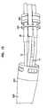
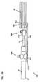
- FIG. 1is a perspective view of a fiber cable clamp installed on a fiber optic cable according to an embodiment of the present disclosure
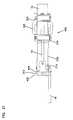
- FIG. 2is a cross-sectional side view of the fiber cable clamp according to the embodiment of FIG. 1 ;
- FIG. 3is a perspective view of the cable fiber separator used in the fiber cable clamp of FIG. 1 ;
- FIG. 4is a top plan view of the cable fiber separator of FIG. 3 ;
- FIG. 5is a cross-sectional side view of the cable fiber separator of FIG. 3 ;
- FIG. 6is a perspective view of a retention plate of the fiber cable clamp of FIG. 1 ;
- FIG. 7is a top plan view of the retention plate of FIG. 6 ;
- FIG. 8is a perspective view of a fiber sheath grip of the fiber cable clamp of FIG. 1 ;
- FIG. 9is a front plan view of the fiber sheath grip of FIG. 8 ;
- FIG. 10is a side plan view of the fiber sheath grip of FIG. 8 ;
- FIG. 11is a perspective view of a cable clamp mounting structure of the fiber cable clamp of FIG. 1 ;
- FIG. 12is a front plan view of the cable clamp mounting structure of FIG. 11 ;
- FIG. 13is a top plan view of the cable clamp mounting structure of FIG. 11 ;
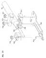
- FIG. 14is a perspective view of a second possible embodiment of a fiber cable clamp installed on a fiber optic cable
- FIG. 15is a disassembled perspective view of the fiber cable clamp of FIG. 14 ;
- FIG. 16is a perspective view of a cable separator housing of the fiber cable clamp of FIG. 14 ;
- FIG. 17is a side plan view of the cable separator housing of FIG. 16 ;
- FIG. 18is a cross-sectional side view of the cable separator housing of FIG. 16 ;
- FIG. 19is a front plan view of the cable separator housing of FIG. 16 ;
- FIG. 20is a perspective view of a separator insert of the fiber cable clamp of FIG. 14 ;
- FIG. 21is a front plan view of the separator insert of FIG. 20 ;
- FIG. 22is a cross-sectional side view of the separator insert of FIG. 20 ;
- FIG. 23is a perspective view of a retention plate of the fiber cable clamp of FIG. 14 ;
- FIG. 24is a front plan view of the retention plate of FIG. 23 ;
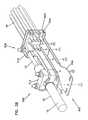
- FIG. 25is a perspective view of a third possible embodiment of a fiber cable clamp installable onto a fiber optic cable
- FIG. 26is an exploded perspective view of the fiber cable clamp of FIG. 25 ;
- FIG. 27is a side plan view of the fiber cable clamp of FIG. 25 ;
- FIG. 28is an exploded perspective view of a cable fiber separator used in the fiber cable clamp of FIG. 25 ;
- FIG. 29is a perspective view of a fourth possible embodiment of a fiber cable clamp installable onto a fiber optic cable
- FIG. 30is an exploded perspective view of the fiber cable clamp of FIG. 29 ;
- FIG. 31is a side plan view of the fiber cable clamp of FIG. 29 ;
- FIG. 32is a side plan view of the fiber cable clamp of FIG. 29 , opposite the view of FIG. 31 ;
- FIG. 33is an exploded perspective view of a cable fiber separator used in the fiber cable clamp of FIG. 29 ;
- FIG. 34is a perspective view of a fifth possible embodiment of a fiber cable clamp installable onto a fiber optic cable
- FIG. 35is a is a side plan view of the fiber cable clamp of FIG. 34 ;
- FIG. 36is a perspective view of the fiber cable clamp of FIG. 34 , with the cable fiber separator removed;
- FIG. 37is an exploded perspective view of the fiber cable clamp of FIG. 34 , with the cable fiber separator removed;
- FIG. 38is a perspective view of a sixth possible embodiment of a fiber cable clamp installable onto a fiber optic cable
- FIG. 39is a side plan view of the fiber cable clamp of FIG. 38 ;
- FIG. 40is a perspective view of a cable sheath grip used in conjunction with the fiber cable clamps of the present disclosure, installed onto a multifiber optical cable;
- FIG. 41is an exploded view of the cable sheath grip of FIG. 40 ;
- FIG. 42is a side view of the cable sheath grip of FIG. 40 .
- the present disclosurerelates to a fiber cable clamp configured to be mounted to a fiber optic cable having a cable sheath and a strength member.
- the fiber cable clampwhen mounted to the fiber optic cable, maintains the relative axial locations of the cable sheath and the strength member to prevent signal loss along the cable at a wide variety of temperatures.
- the fiber cable clamp 100is designed for use with a multifiber optical cable 10 that includes a cable sheath 12 and a strength member 14 .
- the cable sheath 12surrounds a plurality of optical fibers 16 , which are in turn grouped around the strength member 14 .
- the fiber cable clamp 100is designed to maintain the relative axial locations of the cable sheath 12 and the strength member 14 , despite possible positional shifts due to thermal expansion or contraction of the sheath and strength members at different rates.
- the fiber cable clamp 100includes a cable separator 102 and a plurality of fiber sheath grips 104 .
- the cable separator 102shown in detail in FIGS. 3-7 , includes a first disk 106 and a second disk, shown as a fiber retention plate 108 .
- the first diskincludes a plurality of openings 110
- the fiber retention plate 108has a corresponding plurality of openings 111 .
- the cable openings 110 , 111 of the disk 106 and plate 108are disposed in concentric circles around a center axis, and coordinate to provide a transverse path 113 allowing fibers to pass therethrough.
- the cable openings 110 , 111may be disposed radially from the center point or in some other configuration.
- the transverse paths 113 through the openings 110 , 111allow the optical fibers 16 to pass through the disk 106 and retention plate 108 .
- the optical fibers 16are sheathed in furcation tubes 18 inserted through the paths 113 , for protecting the optical fibers 16 .
- One or more optical fibersmay be sheathed in each furcation tube 18 , which may be made of a plastic or some other flexible material.
- the retention plate 108acts to grip the furcation tubes 18 to prevent axial movement of the furcation tubes relative to the fiber cable clamp 100 .
- Disk 106also includes a central strength member clamp 112 and mounting holes 114 .
- the strength member clamp 112provides an end limit to how far the strength member 14 can protrude beyond the cable sheath 12 .
- the strength member clamp 112is located in axial alignment with the fiber optic cable 10 , and accepts insertion of the strength member 14 .
- the strength member clamp 112is formed in the disk 106 , and the fiber retention plate 108 includes a central opening 115 sized to allow the strength member clamp 112 to pass therethrough.
- the openings 110 in the disk 106are tapered at the edges, while the openings 111 in the fiber retention plate 108 are untapered.
- the openings 110are larger than the openings 111 . In such configurations, the openings 111 in the fiber retention plate 108 grip the furcation tubes 18 while the furcation tubes 18 are moveable axially within the openings 110 .
- Other configurationsare possible as well.
- An opening 117is transversely located in the strength member clamp 112 and configured to accept a fastener, shown as a set screw 116 .
- the opening 117 and accompanying set screw 116are configured to engage the strength member 14 to prevent it from receding from and disengaging with the strength member clamp 112 .
- the strength member clamp 112includes a cylinder having an opening on one end constructed to fit around the central strength member 14 of the cable 10 . Additional openings in the side of the cylinder accept the set screw 116 .
- the mounting holes 114are configured to connect the cable separator 102 to the fiber sheath grips 104 .
- mounting holes 114 at opposed edges of the cable separator 102accept a fastener 119 designed to hold the fiber sheath grips 104 and the cable separator 102 together.
- the cable separator 102is pivotally connected to two fiber sheath grips 104 via the fastener 119 and mounting holes 114 .
- the fastener 119is a screw inserted through the fiber sheath grip 104 and cable separator 102 .
- more or fewer mounting holes 114 and associated fiber sheath grips 104may be used, and other fasteners 119 may be used as well, and are generally associated with the number of fibers 16 included in the cable 10 .
- the fiber sheath grips 104shown in detail in FIGS. 8-10 , connect the cable separator 102 to the cable sheath 12 and grip the cable sheath 12 , thereby substantially fixing the axial positional relationship between the strength member 14 and the cable sheath 12 of the cable 10 .
- the fiber sheath grips 104flare to a point including an opening configured to receive the fastener for connection to the cable separator 102 .
- each of the fiber sheath grips 104includes a plurality of sheath grip teeth 118 along at least a portion of the lateral edges of the grip 104 .
- the sheath grip teeth 118are oriented toward the cable sheath 12 to engage the sheath and prevent it from slipping along the sheath grips 104 when engaged with the cable 10 .
- a hose clamp 120surrounds the optical cable 10 and the fiber sheath grips 104 at a position proximate to the plurality of teeth, such that the sheath grips 104 are compressed into the cable sheath 12 .
- two fiber sheath grips 104are placed on opposed sides of the cable 10 , and include sheath grip teeth 118 along a portion of the cable contacted by the fiber sheath grips 104 .
- more or fewer teeth, and various alternative numbers/shapes of fiber sheath gripsare possible as well.
- the fiber sheath grips 104optionally include one or more protrusions 122 incorporated on the outer surface.
- the protrusionsare configured to provide a location for attachment of a mounting structure 124 , shown in FIGS. 11-13 .
- the mounting structureincludes a first attachment location 125 , which includes openings 126 configured to mate with the protrusions to affix the mounting structure to the cable clamp 100 .
- the mounting structure 124also includes second attachment locations 128 , which include openings 130 configured to allow attachment of the mounting structure 124 and cable clamp 100 to various locations.
- second attachment locations 128which include openings 130 configured to allow attachment of the mounting structure 124 and cable clamp 100 to various locations.
- Various additional configurations of the mounting structureare possible as well.
- the fiber cable clamp 200includes a sheath grip housing 202 and a cable fiber separator, shown as a fiber separation insert 204 .
- the sheath grip housing 202shown in detail in FIGS. 16-19 includes a flare tube 206 , and a plurality of sheath grip members 208 .
- the sheath grip members 208extend from the flare tube 206 , and are configured to surround a cable 10 , as in the embodiment of FIGS. 1-13 .
- the sheath grip members 208each include a plurality of ridges 210 configured to grip the fiber sheath 12 when the fiber cable clamp 200 is installed on a cable 10 .
- three sheath grip members 208extend along the cable 10 from the flare tube 206 , and the ridges 210 reside on interior surfaces of the sheath grip members 208 facing the cable sheath 12 , preventing sheath from slipping through the sheath grip members.
- more or fewer sheath grip members 208having more or fewer ridges 210 than shown in FIGS. 12-20 may extend from the flare tube 206 .
- a fiber separation insert 204is received within the flare tube 206 .
- the fiber separation insert 204extends from the flare tube 206 , and is configured to be fixedly attached to the flare tube.
- the insert 204includes a plurality of openings 212 configured to allow optical fibers 16 of the cable to pass through, along with furcation tubes 18 installed over the optical fibers.
- Each of the openings 212allow passage of one or more furcation tubes 18 and optical fibers 16 .
- two or more optical fibers 16 and corresponding furcation tubes 18fit through each opening 212 .
- a single optical fiber 16may pass through each opening 212 , depending upon the number of openings in the insert 204 and the number of fibers 16 in the cable 10 .
- the fiber separation insert 204includes a strength member clamp 214 integrated with the insert 204 , along a central axis.
- the strength member clamp 214extends beyond the flare tube 206 , and is configured to accept the central strength member 14 of the cable 10 to clamp the central strength member in place within the insert 204 .
- the strength member clamp 214includes a fastener opening 216 in the portion of the clamp protruding from the flare tube 206 .
- the fastener opening 216is configured to accept a fastener 218 , in the embodiment of FIGS. 12-20 shown as a set screw.
- the fastener opening 216 and set screwhold the strength member 14 in a constant position within the strength member clamp 214 , to prevent the strength member 14 from receding from the clamp.
- the fastener opening 216can accept various types of fasteners, such as an adjustable pin, clamp, or other connector designed to hold the strength member 14 . Additional types of fasteners 218 are possible as well.
- a retention plate 220seen in FIGS. 15 and 23 - 24 , is sized to fit within the flare tube 206 , and includes a plurality of openings 222 configured to allow furcation tubes 18 and optical fibers 16 to pass through.
- the retention plate 220is installed onto the fibers 16 and furcation tubes 18 prior to the fiber separation insert 204 .
- the openings 222 in the retention plateact to grip the furcation tubes 18 in a manner analogous to the retention plate 108 of the embodiment of FIGS. 1-13 .
- a central opening 224allows the strength member to pass through the retention plate and enter the strength member clamp 214 .
- An optional hose clamp 222encircles the cable 10 and sheath grip members 208 .
- the hose clamp 222compresses the sheath grip members 208 into the sheath 12 of the fiber optic cable 10 , to assist in preventing the sheath from slipping from the grip of the sheath grip members 208 by adding an adjustable amount of compression force on the sheath grip members.
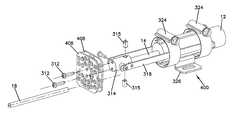
- the fiber cable clamp 300includes a cable separator 302 and a fiber sheath grip assembly 304 .
- the cable separator 302shown in detail in FIG. 28 , includes a pair of disks 306 , 308 .
- the disksinclude complementary openings 310 , 311 , respectively, disposed to provide a transverse path allowing optical fibers to pass therethrough.
- the disks 306 , 308are detachably connected by one or more fasteners, such as screws 312 .
- Each pair of openings 310 , 311allow passage of one or more furcation tubes 18 through both disks, and at least one of the openings is sized to grip the furcation tubes 18 inserted through the disks, as described above in connection with the clamp 100 of FIGS. 1-13 .
- spacers 313are affixed between the disks 306 , 308 by the screws 312 to assist in insertion of the furcation tubes 18 .
- the disksprevent axial movement of furcation tubes 18 relative to the fiber cable clamp 300 .
- the disks 306 , 308are generally circular in shape and affixed to a central strength member clamp 314 by the screws 312 .
- the strength member clamp 314affixes to a strength member 14 of the optical cable protruding from the cable sheath 12 .
- the strength member clamp 314is axially alighted with the fiber optic cable 10 , and accepts insertion of the strength member 14 .
- Fasteners 315are insertable into the strength member clamp 314 to affix the strength member clamp to the strength member 14 .
- the cable sheath grip assembly 304optionally includes cable sheath grip 316 , and one or more extensions 318 affixable to the strength member clamp 314 .
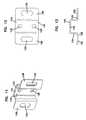
- the cable sheath grip 316shown in detail in FIGS. 40-42 , includes a grip member 318 having a plurality of ridges 319 facing the cable sheath 12 .
- An insert 320passes under the cable sheath 12 and includes a fastener location 321 .
- a fastenersuch as one or more nuts 322 , can thread onto the fastener location or otherwise attach the grip member 318 to the insert 320 , thereby engaging and holding the cable sheath 12 therebetween by pressing the ridges 319 toward the insert 320 .
- hose clamps 324may be used to affix the cable sheath grip assembly 304 to the cable sheath 12 .
- Hose clamps 324provide concentric pressure on the cable sheath 12 , analogous to the hose clamps 120 , 222 , described above.
- a mounting structure 326analogous to mounting structure 124 of FIGS. 11-13 is optionally affixed along one or more of the extensions 318 as well.
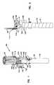
- the fiber cable clamp 400generally corresponds to the clamp 300 of FIGS. 25-29 , but includes disks 406 , 408 in place of the disks 306 , 308 of FIGS. 25-28 .
- Disks 406 , 408are generally rectangular in shape, although the disks optionally have radiused corners.
- the disks 406 , 408include openings 410 , 411 , respectively, which are arranged non-radially about the strength member clamp 314 . Additional shapes and configurations of the disks 406 , 408 and openings 410 , 411 beyond those shown are possible as well.
- the fiber cable clamp 500includes a cable separator 502 and a cable clamp assembly 504 .
- the cable separator 502is a bent metal fiber separator having a plurality of openings 503 defining transverse paths allowing optical fibers 16 to pass through the separator.
- the openings 503grip furcation tubes 18 shrouding the optical fibers 16 , preventing axial movement of the furcation tubes along the length of the cable 10 .
- the cable clamp assembly 504 to which the separator 502 is connectedincludes a sheath grip assembly 506 and a strength member clamp 508 attached together at a base plate 510 .
- the common affixation of the strength member clamp 508 and the sheath grip assembly 506 to the base plate 510maintains the axial positions of the strength member 14 and the cable sheath 12 with respect to each other.
- the sheath grip assembly 506includes a pair of sheath grip members 512 , or yokes, which can be bolted to extensions of the base plate 510 using nuts 515 or other fasteners to form a circular, ridged ring that surrounds and grips the cable sheath 12 .
- the sheath grip assemblyalso optionally includes an additional cable sheath grip 316 , as shown in FIGS. 40-42 and previously described.
- the strength member clamp 508includes a post 514 , such as a threaded bolt, extending from the base plate 510 and a cap 516 which can be affixed over the post 514 using a fastener such as a nut 515 .
- the cap 516includes a retention mechanism for gripping the strength member 14 when the cap 516 is fastened to the post 514 .
- Other configurations of the strength member clampare possible as well.
- the cable sheath grip 316 and strength member clamp 508cooperate to maintain the relative axial position of the cable sheath 12 to the strength member 14 .
- the base plate 510includes a plurality of mounting locations (not shown) which allow the base plate to be mounted to a wall, fiber cabinet, or other structure.
- the mounting locationsalso optionally provide a means by which the cable fiber separator 502 can be attached to the cable clamp assembly 504 , for example by bolts or other attachment configurations.
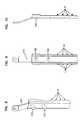
- FIGS. 38-39show a fiber cable clamp 600 according to a sixth possible embodiment of the present disclosure.
- the fiber cable clamp 600generally corresponds to the clamp 500 of FIGS. 34-37 ; however, in this additional embodiment, the cable separator 502 of the clamp 600 includes two generally parallel rectangular walls 602 , 603 , which each include complementary openings 503 defining transverse paths allowing optical fibers 16 to pass through the separator.
- the openings 503 in each wallcan be used for holding furcation tubes 18 .
- the openings 503allow a furcation tube to be inserted through each wall, and the pair of walls 602 , 603 coordinate to assist in gripping the furcation tubes.
- the openings 503grip furcation tubes 18 shrouding the optical fibers 16 , preventing axial movement of the furcation tubes along the length of the cable 10 .
- the strength member clamp(e.g. strength member clamp 314 ) is clamped to a central strength member 14 of the cable 10 .
- the extensionse.g. extensions 318
- the disks or other cable fiber separator component of the selected embodiment of the cable clampe.g. disks 106 and 108 , disks 306 and 308 , or disks 406 and 408
- Furcation tubes 18are installed over the cables 16 and inserted into openings in the disks or separator, as described above.
- the disks or separator of the selected embodimentare then connected onto the strength member clamp if not already integrated therewith, such as disk 106 of FIGS. 1-5 .
- Other methods of assemblyare possible as well, depending upon the chosen embodiment of the fiber optic cable clamp or the configuration of optical fibers employed.
Landscapes
- Physics & Mathematics (AREA)
- General Physics & Mathematics (AREA)
- Optics & Photonics (AREA)
- Light Guides In General And Applications Therefor (AREA)
Abstract
Description
Claims (14)
Priority Applications (1)
| Application Number | Priority Date | Filing Date | Title |
|---|---|---|---|
| US12/772,567US8364000B2 (en) | 2007-10-22 | 2010-05-03 | Fiber optic cable clamp |
Applications Claiming Priority (2)
| Application Number | Priority Date | Filing Date | Title |
|---|---|---|---|
| US11/975,904US7711236B2 (en) | 2007-10-22 | 2007-10-22 | Fiber optic cable clamp |
| US12/772,567US8364000B2 (en) | 2007-10-22 | 2010-05-03 | Fiber optic cable clamp |
Related Parent Applications (1)
| Application Number | Title | Priority Date | Filing Date |
|---|---|---|---|
| US11/975,904DivisionUS7711236B2 (en) | 2007-10-22 | 2007-10-22 | Fiber optic cable clamp |
Publications (2)
| Publication Number | Publication Date |
|---|---|
| US20100215331A1 US20100215331A1 (en) | 2010-08-26 |
| US8364000B2true US8364000B2 (en) | 2013-01-29 |
Family
ID=40303572
Family Applications (2)
| Application Number | Title | Priority Date | Filing Date |
|---|---|---|---|
| US11/975,904ActiveUS7711236B2 (en) | 2007-10-22 | 2007-10-22 | Fiber optic cable clamp |
| US12/772,567Expired - Fee RelatedUS8364000B2 (en) | 2007-10-22 | 2010-05-03 | Fiber optic cable clamp |
Family Applications Before (1)
| Application Number | Title | Priority Date | Filing Date |
|---|---|---|---|
| US11/975,904ActiveUS7711236B2 (en) | 2007-10-22 | 2007-10-22 | Fiber optic cable clamp |
Country Status (3)
| Country | Link |
|---|---|
| US (2) | US7711236B2 (en) |
| EP (1) | EP2203771A1 (en) |
| WO (1) | WO2009055453A1 (en) |
Cited By (10)
| Publication number | Priority date | Publication date | Assignee | Title |
|---|---|---|---|---|
| US20140010514A1 (en)* | 2012-07-09 | 2014-01-09 | Avago Technologies General Ip (Singapore) Pte. Ltd. | Metal strain relief device for use in an optical communications system, an optical fiber cable that employs the strain relief device, and a method |
| US20140140664A1 (en)* | 2012-11-19 | 2014-05-22 | Andrew Llc | Optical fiber / electrical composite cable assembly with sealed breakout kit |
| US8950954B2 (en) | 2012-07-31 | 2015-02-10 | Avago Technologies General Ip ( Singapore) Pte. Ltd. | Side-edge mountable parallel optical communications module, an optical communications system that incorporates the module, and a method |
| US9054804B2 (en) | 2012-07-09 | 2015-06-09 | Avago Technologies General Ip (Singapore) Pte. Ltd. | Electromagnetic interference (EMI) shielding device and method for use in an optical communications system |
| US9140872B2 (en) | 2013-09-17 | 2015-09-22 | Panduit Corp. | Hydra cable assembly and components thereof |
| US9494761B2 (en) | 2014-07-31 | 2016-11-15 | All Systems Broadband, Inc. | Bracket for securing multiple fiber optic cables to a termination box |
| US11269145B2 (en) | 2020-07-29 | 2022-03-08 | Google Llc | Cable connection structure for fiber optic hardware management |
| US11287595B2 (en)* | 2018-12-04 | 2022-03-29 | Hubbell Incorporated | Fiber optic dead-end cable clamp with central actuator |
| US20220229253A1 (en)* | 2019-04-17 | 2022-07-21 | Commscope Technologies Llc | Telecommunications cable guide |
| US12282201B2 (en) | 2022-02-15 | 2025-04-22 | Google Llc | Splicing tray utilized in fiber optic patch panel assembly for fiber optic cable connection management |
Families Citing this family (36)
| Publication number | Priority date | Publication date | Assignee | Title |
|---|---|---|---|---|
| DE202006006018U1 (en)* | 2006-04-11 | 2006-07-13 | CCS Technology, Inc., Wilmington | Apparatus for intercepting optical waveguide cables |
| US7711236B2 (en)* | 2007-10-22 | 2010-05-04 | Adc Telecommunications, Inc. | Fiber optic cable clamp |
| US7664363B1 (en)* | 2008-06-25 | 2010-02-16 | Mowery Sr Arthur J | Apparatus and method to protect fiber ribbons |
| US8705930B2 (en)* | 2010-06-25 | 2014-04-22 | Adc Telecommunications, Inc. | Transition housing and cap for fiber breakout assembly |
| US8410909B2 (en) | 2010-07-09 | 2013-04-02 | Corning Incorporated | Cables and connector assemblies employing a furcation tube(s) for radio-frequency identification (RFID)-equipped connectors, and related systems and methods |
| US11251608B2 (en) | 2010-07-13 | 2022-02-15 | Raycap S.A. | Overvoltage protection system for wireless communication systems |
| US8780519B2 (en) | 2011-02-08 | 2014-07-15 | Raycap, S.A. | Modular and weather resistant overvoltage protection system for wireless communication systems |
| US8774585B2 (en) | 2011-04-12 | 2014-07-08 | Adc Telecommunications, Inc. | Strain-relief bracket for fiber optic closure |
| US8625952B2 (en)* | 2011-07-13 | 2014-01-07 | Corning Cable Systems Llc | Fiber optic cable mounting adapters, and related fiber optic cable assemblies and methods |
| US8873926B2 (en)* | 2012-04-26 | 2014-10-28 | Corning Cable Systems Llc | Fiber optic enclosures employing clamping assemblies for strain relief of cables, and related assemblies and methods |
| EP2706635B1 (en)* | 2012-09-05 | 2017-03-08 | Tyco Electronics Nederland B.V. | End cap, arrangement and kit for terminating a transmission cable |
| WO2014071021A1 (en)* | 2012-10-31 | 2014-05-08 | Adc Telecommunications, Inc. | Anchoring cables to rack with cable clamp arrangements |
| US20140133822A1 (en)* | 2012-11-13 | 2014-05-15 | Cesar Alejandro de los Santos Campos | Rotatable furcation assembly |
| US9201205B2 (en)* | 2013-01-16 | 2015-12-01 | 3M Innovative Properties Company | Telecommunications cable inlet device |
| US9229186B2 (en) | 2013-02-14 | 2016-01-05 | Commscope Technologies Llc | Self engaging port plug |
| US9640986B2 (en) | 2013-10-23 | 2017-05-02 | Raycap Intellectual Property Ltd. | Cable breakout assembly |
| CN104656190A (en)* | 2013-11-15 | 2015-05-27 | 深圳市华为安捷信电气有限公司 | Fiber stripping device and communication equipment |
| US9535230B2 (en) | 2014-01-31 | 2017-01-03 | Senko Advanced Components, Inc. | Integrated fiber optic cable fan-out connector |
| US10054753B2 (en) | 2014-10-27 | 2018-08-21 | Commscope Technologies Llc | Fiber optic cable with flexible conduit |
| US9575277B2 (en)* | 2015-01-15 | 2017-02-21 | Raycap, S.A. | Fiber optic cable breakout assembly |
| AU2015207954C1 (en) | 2015-07-31 | 2022-05-05 | Adc Communications (Australia) Pty Limited | Cable breakout assembly |
| US10802237B2 (en) | 2015-11-03 | 2020-10-13 | Raycap S.A. | Fiber optic cable management system |
| US9971119B2 (en) | 2015-11-03 | 2018-05-15 | Raycap Intellectual Property Ltd. | Modular fiber optic cable splitter |
| EP3403125B1 (en)* | 2016-03-18 | 2021-07-14 | Commscope Technologies LLC | Fiber-optic cable fanout conduit arrangement and method for organizing optical fibers |
| US10890730B2 (en) | 2016-08-31 | 2021-01-12 | Commscope Technologies Llc | Fiber optic cable clamp and clamp assembly |
| US10914909B2 (en) | 2016-10-13 | 2021-02-09 | Commscope Technologies Llc | Fiber optic breakout transition assembly incorporating epoxy plug and cable strain relief |
| WO2018098324A1 (en)* | 2016-11-23 | 2018-05-31 | Commscope Technologies Llc | Fiber optic furcation assemblies, methods, and systems |
| WO2018136812A1 (en) | 2017-01-20 | 2018-07-26 | Raycap S.A. | Power transmission system for wireless communication systems |
| CN110622051A (en) | 2017-05-08 | 2019-12-27 | 康普技术有限责任公司 | Optical fiber branch transition assembly |
| US10712519B2 (en)* | 2017-06-28 | 2020-07-14 | Corning Research & Development Corporation | High fiber count pre-terminated optical distribution assembly |
| US10330881B1 (en) | 2017-12-21 | 2019-06-25 | Afl Telecommunications Llc | Optical fiber furcation assemblies |
| CA3095881A1 (en) | 2018-04-02 | 2019-10-10 | Senko Advanced Components, Inc | Hybrid ingress protected connector and adapter assembly |
| US10971928B2 (en) | 2018-08-28 | 2021-04-06 | Raycap Ip Assets Ltd | Integrated overvoltage protection and monitoring system |
| US11677164B2 (en) | 2019-09-25 | 2023-06-13 | Raycap Ip Assets Ltd | Hybrid antenna distribution unit |
| US12237134B2 (en) | 2021-12-28 | 2025-02-25 | Raycap Ip Assets Ltd | Circuit protection for hybrid antenna distribution units |
| US20240012217A1 (en)* | 2022-07-05 | 2024-01-11 | Corning Research & Development Corporation | Connection interface for fiber optic cable assemblies and method of making such cable assemblies |
Citations (72)
| Publication number | Priority date | Publication date | Assignee | Title |
|---|---|---|---|---|
| US712765A (en) | 1901-11-22 | 1902-11-04 | Joseph H Cole | Clamping-band. |
| US1390654A (en) | 1921-03-30 | 1921-09-13 | Henry A Stork | Antislip rope and cable clamp |
| DE679938C (en) | 1937-12-11 | 1939-08-17 | Walter Eugen Fischer | Two-part spacer clip made of molded insulating material |
| US2355166A (en) | 1941-07-22 | 1944-08-08 | Albert & J M Anderson Mfg Co | Cable clamping means |
| US2642474A (en) | 1949-09-14 | 1953-06-16 | Honeywell Regulator Co | Electrical connector |
| US2823248A (en) | 1953-09-29 | 1958-02-11 | Amphenol Electronics Corp | Self-sealing cable clamp |
| AT221618B (en) | 1961-02-08 | 1962-06-12 | Bonum Werk Ges M B H | Cable clamp |
| US3160457A (en) | 1961-12-02 | 1964-12-08 | Fischer Walter | Electrical connecting device |
| US3494580A (en) | 1967-09-13 | 1970-02-10 | Oswald Willy Thorsman | Cable clamp |
| US3624679A (en) | 1970-01-23 | 1971-11-30 | George William Ziegler Jr | Coaxial stake for high-frequency cable termination |
| US3673546A (en) | 1970-04-20 | 1972-06-27 | John L Green | Electrical connectors |
| US4128918A (en) | 1976-11-29 | 1978-12-12 | Matrix Iv, Inc. | Adjustable snap-on-clamp |
| US4243290A (en) | 1978-10-30 | 1981-01-06 | Williams Robert A | Shield termination means for electrical connector |
| US4317262A (en) | 1979-09-12 | 1982-03-02 | Ideal Industries, Inc. | Releasable cable clamp |
| US4447120A (en) | 1981-10-05 | 1984-05-08 | International Telephone & Telegraph Corporation | Fiber optic cable clamp |
| US4542858A (en) | 1984-05-23 | 1985-09-24 | The United States Of America As Represented By The Administrator Of The National Aeronautics And Space Administration | Rotatable electric cable connecting system |
| EP0167738A2 (en) | 1984-06-04 | 1986-01-15 | Allied Corporation | Electrical connector having means for retaining a coaxial cable |
| US4639064A (en) | 1986-02-28 | 1987-01-27 | Allied Corporation | Anti-decoupling resisting and EMI shielding means for an electrical connector assembly |
| US4657425A (en) | 1985-02-14 | 1987-04-14 | Nifco, Inc. | Device for locking rod against movement in extending and contracting directions |
| US4717792A (en) | 1984-08-03 | 1988-01-05 | Sterritt James L | Sealed jointing apparatus |
| US4799902A (en) | 1987-08-19 | 1989-01-24 | Amp Incorporated | Triaxial electrical cable connector |
| US4813887A (en) | 1986-09-05 | 1989-03-21 | Amp Incorporated | Electrical connector for multiple outer conductor coaxial cable |
| US4875864A (en) | 1989-03-13 | 1989-10-24 | Campbell Marvin J | Ground clamp for coaxial cable junction block |
| USD307541S (en) | 1988-01-12 | 1990-05-01 | E. I. Du Pont De Nemours And Company | Combined clip and mounting stud |
| US4936795A (en) | 1988-10-04 | 1990-06-26 | Hirose Electric Co., Ltd. | Electrical connector |
| US4938714A (en) | 1988-10-04 | 1990-07-03 | Hirose Electric Co., Ltd. | Electrical connector |
| US4991928A (en) | 1990-02-20 | 1991-02-12 | Siecor Corporation | Movable clamp for fiber optic enclosures |
| US5007862A (en) | 1990-06-15 | 1991-04-16 | Amp Incorporated | Shielded connector having a multiply orientable housing |
| US5048918A (en) | 1990-02-07 | 1991-09-17 | Raychem Corporation | Optical fiber cable termination |
| US5230489A (en) | 1992-08-03 | 1993-07-27 | Panduit Corp. | Wire retention clip |
| US5243139A (en) | 1992-05-26 | 1993-09-07 | Heyco Molded Products, Inc. | Lay in strain relief bushing for variable wire sizes |
| US5307037A (en) | 1992-10-28 | 1994-04-26 | General Electric Company | Shim lead assembly with flexible castellated connector for superconducting magnet |
| USD347384S (en) | 1993-07-02 | 1994-05-31 | Panduit Corp. | Wire retention clip |
| DE4301269A1 (en) | 1993-01-19 | 1994-07-21 | Osi Kommunikations Und Systemt | Construction and fitting kit for optical transmission lines |
| US5469613A (en) | 1992-07-10 | 1995-11-28 | Raychem Corporation | Tool for connecting a coaxial cable terminus to a connection jack |
| EP0716324A1 (en) | 1994-12-08 | 1996-06-12 | Alcatel Cable Interface | Fixing device for at least one fibre optical cable and device orientated splicebox |
| US5573423A (en) | 1995-01-18 | 1996-11-12 | Lin; Kuang-Ts'an | Innovative distribution cable mounting device |
| US5645450A (en) | 1994-11-29 | 1997-07-08 | Yazaki Corporation | Shielded connector |
| US5675124A (en) | 1996-04-30 | 1997-10-07 | Stough; Robert Eugene | Grommet for a fiber optic enclosure |
| US5675128A (en) | 1994-10-20 | 1997-10-07 | Simon; Hans | Cable terminal |
| US5725185A (en) | 1996-02-29 | 1998-03-10 | Electric Motion Company, Inc. | Cable clamp bracket assembly |
| US5773759A (en) | 1995-12-07 | 1998-06-30 | Agro Ag | Screw-type conduit fitting for a shielded cable |
| US5785554A (en) | 1996-03-28 | 1998-07-28 | Ohshiro; Yoshio | Coaxial connector |
| US5793921A (en) | 1995-03-20 | 1998-08-11 | Psi Telecommunications, Inc. | Kit and method for converting a conductive cable closure to a fiber optic cable closure |
| US5800195A (en) | 1995-05-25 | 1998-09-01 | Yazaki Corporation | Dewing-trouble-prevented water-proof connector |
| US5807138A (en) | 1995-08-11 | 1998-09-15 | Guiol; Eric | End housing for a plug-in connector |
| US5862291A (en) | 1994-02-08 | 1999-01-19 | Miniflex Limited | Cable routing device |
| US5937488A (en) | 1998-07-13 | 1999-08-17 | Tyton Hellerman Corporation | Brakeline to axle clamp |
| US5967852A (en) | 1998-01-15 | 1999-10-19 | Adc Telecommunications, Inc. | Repairable connector and method |
| US5998737A (en) | 1996-11-22 | 1999-12-07 | Krone Aktiengesellschaft | Clamping device |
| US6126122A (en) | 1997-11-06 | 2000-10-03 | Sioux Chief Manufacturing Co., Inc. | Double ratchet arm pipe clamp |
| US6146192A (en) | 1999-03-31 | 2000-11-14 | Adc Telecommunications, Inc. | Bulkhead connector system including angled adapter |
| WO2000072072A1 (en) | 1999-05-19 | 2000-11-30 | Tyco Electronics Raychem Nv | Cable termination |
| US6164605A (en) | 1998-11-04 | 2000-12-26 | General Motors Corporation | Brake line captured band clamp |
| US6203331B1 (en) | 1999-11-05 | 2001-03-20 | Hon Hai Precision Ind. Co., Ltd. | Land grid array connector having a floating housing |
| US6206331B1 (en) | 1998-07-30 | 2001-03-27 | Ewd, L.L.C. | D-shaped wire harness clip with ratchet lock |
| US6398169B1 (en) | 1998-04-03 | 2002-06-04 | Sofanou S.A. | Device for securing longitudinal elements on a panel and tool for installing the same |
| FR2822250A1 (en) | 2001-03-14 | 2002-09-20 | Sagem | High capacity optical cable separation/connection mechanism having fixing slab with holes and fibre protection tubes threaded through/screws mechanism position holding two protection tubes |
| US6466725B2 (en) | 2000-11-29 | 2002-10-15 | Corning Cable Systems Llc | Apparatus and method for splitting optical fibers |
| US6463631B2 (en) | 2000-05-17 | 2002-10-15 | Kitagawa Industries Co., Inc. | Binding tool |
| US6487344B1 (en) | 1998-08-04 | 2002-11-26 | Pouyet S.A. | Optical fiber cable inlet device |
| USD473130S1 (en) | 2001-08-28 | 2003-04-15 | Gloria Island Ltd. | Cable clamp with grounding connection |
| US6595472B1 (en) | 2001-12-28 | 2003-07-22 | Preformed Line Products Company | Cable clamp |
| US6726166B2 (en) | 2000-03-11 | 2004-04-27 | All-Points Equipment Co., L.P. | Cable clamp |
| US6846988B2 (en) | 2002-01-18 | 2005-01-25 | Adc Telecommunications, Inc. | Triaxial connector including cable clamp |
| WO2005020400A1 (en) | 2003-08-20 | 2005-03-03 | Ccs Technology, Inc. | Clamping device for optical cables, and cable joint |
| US6994300B2 (en) | 2002-05-23 | 2006-02-07 | Airbus France | Device for fastening elongate objects onto a flat support |
| US20060233509A1 (en) | 2005-04-14 | 2006-10-19 | Craig Ray | Optical fiber repair apparatus with adjustable guide member and methods for using the same |
| US7178203B2 (en) | 2005-02-28 | 2007-02-20 | Illinois Tool Works Inc | Anti-removal ratchet clip |
| US7223918B2 (en) | 2003-02-25 | 2007-05-29 | A. Raymond & Cie | Cable clamp |
| US7254307B2 (en) | 2005-06-03 | 2007-08-07 | Telect Inc. | Fiber breakout system |
| US7711236B2 (en)* | 2007-10-22 | 2010-05-04 | Adc Telecommunications, Inc. | Fiber optic cable clamp |
Family Cites Families (3)
| Publication number | Priority date | Publication date | Assignee | Title |
|---|---|---|---|---|
| US347384A (en)* | 1886-08-17 | Steam-boiler | ||
| US307541A (en)* | 1884-11-04 | Metallic pile | ||
| KR100238795B1 (en)* | 1997-03-03 | 2000-01-15 | 구본준 | Structure of Liquid Crystal Display and Manufacturing Method of Liquid Crystal Display |
- 2007
- 2007-10-22USUS11/975,904patent/US7711236B2/enactiveActive
- 2008
- 2008-10-22WOPCT/US2008/080763patent/WO2009055453A1/enactiveApplication Filing
- 2008-10-22EPEP08843005Apatent/EP2203771A1/ennot_activeWithdrawn
- 2010
- 2010-05-03USUS12/772,567patent/US8364000B2/ennot_activeExpired - Fee Related
Patent Citations (76)
| Publication number | Priority date | Publication date | Assignee | Title |
|---|---|---|---|---|
| US712765A (en) | 1901-11-22 | 1902-11-04 | Joseph H Cole | Clamping-band. |
| US1390654A (en) | 1921-03-30 | 1921-09-13 | Henry A Stork | Antislip rope and cable clamp |
| DE679938C (en) | 1937-12-11 | 1939-08-17 | Walter Eugen Fischer | Two-part spacer clip made of molded insulating material |
| US2355166A (en) | 1941-07-22 | 1944-08-08 | Albert & J M Anderson Mfg Co | Cable clamping means |
| US2642474A (en) | 1949-09-14 | 1953-06-16 | Honeywell Regulator Co | Electrical connector |
| US2823248A (en) | 1953-09-29 | 1958-02-11 | Amphenol Electronics Corp | Self-sealing cable clamp |
| AT221618B (en) | 1961-02-08 | 1962-06-12 | Bonum Werk Ges M B H | Cable clamp |
| US3160457A (en) | 1961-12-02 | 1964-12-08 | Fischer Walter | Electrical connecting device |
| US3494580A (en) | 1967-09-13 | 1970-02-10 | Oswald Willy Thorsman | Cable clamp |
| US3624679A (en) | 1970-01-23 | 1971-11-30 | George William Ziegler Jr | Coaxial stake for high-frequency cable termination |
| US3673546A (en) | 1970-04-20 | 1972-06-27 | John L Green | Electrical connectors |
| US4128918A (en) | 1976-11-29 | 1978-12-12 | Matrix Iv, Inc. | Adjustable snap-on-clamp |
| US4243290A (en) | 1978-10-30 | 1981-01-06 | Williams Robert A | Shield termination means for electrical connector |
| US4317262A (en) | 1979-09-12 | 1982-03-02 | Ideal Industries, Inc. | Releasable cable clamp |
| US4447120A (en) | 1981-10-05 | 1984-05-08 | International Telephone & Telegraph Corporation | Fiber optic cable clamp |
| US4542858A (en) | 1984-05-23 | 1985-09-24 | The United States Of America As Represented By The Administrator Of The National Aeronautics And Space Administration | Rotatable electric cable connecting system |
| EP0167738A2 (en) | 1984-06-04 | 1986-01-15 | Allied Corporation | Electrical connector having means for retaining a coaxial cable |
| US4717792A (en) | 1984-08-03 | 1988-01-05 | Sterritt James L | Sealed jointing apparatus |
| US4657425A (en) | 1985-02-14 | 1987-04-14 | Nifco, Inc. | Device for locking rod against movement in extending and contracting directions |
| US4639064A (en) | 1986-02-28 | 1987-01-27 | Allied Corporation | Anti-decoupling resisting and EMI shielding means for an electrical connector assembly |
| US4813887A (en) | 1986-09-05 | 1989-03-21 | Amp Incorporated | Electrical connector for multiple outer conductor coaxial cable |
| US4799902A (en) | 1987-08-19 | 1989-01-24 | Amp Incorporated | Triaxial electrical cable connector |
| USD307541S (en) | 1988-01-12 | 1990-05-01 | E. I. Du Pont De Nemours And Company | Combined clip and mounting stud |
| US4936795A (en) | 1988-10-04 | 1990-06-26 | Hirose Electric Co., Ltd. | Electrical connector |
| US4938714A (en) | 1988-10-04 | 1990-07-03 | Hirose Electric Co., Ltd. | Electrical connector |
| US4875864A (en) | 1989-03-13 | 1989-10-24 | Campbell Marvin J | Ground clamp for coaxial cable junction block |
| US5048918A (en) | 1990-02-07 | 1991-09-17 | Raychem Corporation | Optical fiber cable termination |
| US4991928A (en) | 1990-02-20 | 1991-02-12 | Siecor Corporation | Movable clamp for fiber optic enclosures |
| US5007862A (en) | 1990-06-15 | 1991-04-16 | Amp Incorporated | Shielded connector having a multiply orientable housing |
| US5243139A (en) | 1992-05-26 | 1993-09-07 | Heyco Molded Products, Inc. | Lay in strain relief bushing for variable wire sizes |
| US5469613A (en) | 1992-07-10 | 1995-11-28 | Raychem Corporation | Tool for connecting a coaxial cable terminus to a connection jack |
| US5230489A (en) | 1992-08-03 | 1993-07-27 | Panduit Corp. | Wire retention clip |
| US5307037A (en) | 1992-10-28 | 1994-04-26 | General Electric Company | Shim lead assembly with flexible castellated connector for superconducting magnet |
| DE4301269A1 (en) | 1993-01-19 | 1994-07-21 | Osi Kommunikations Und Systemt | Construction and fitting kit for optical transmission lines |
| USD347384S (en) | 1993-07-02 | 1994-05-31 | Panduit Corp. | Wire retention clip |
| US5862291A (en) | 1994-02-08 | 1999-01-19 | Miniflex Limited | Cable routing device |
| US5675128A (en) | 1994-10-20 | 1997-10-07 | Simon; Hans | Cable terminal |
| US5645450A (en) | 1994-11-29 | 1997-07-08 | Yazaki Corporation | Shielded connector |
| EP0716324A1 (en) | 1994-12-08 | 1996-06-12 | Alcatel Cable Interface | Fixing device for at least one fibre optical cable and device orientated splicebox |
| US5573423A (en) | 1995-01-18 | 1996-11-12 | Lin; Kuang-Ts'an | Innovative distribution cable mounting device |
| US5793921A (en) | 1995-03-20 | 1998-08-11 | Psi Telecommunications, Inc. | Kit and method for converting a conductive cable closure to a fiber optic cable closure |
| US5800195A (en) | 1995-05-25 | 1998-09-01 | Yazaki Corporation | Dewing-trouble-prevented water-proof connector |
| US5807138A (en) | 1995-08-11 | 1998-09-15 | Guiol; Eric | End housing for a plug-in connector |
| US5773759A (en) | 1995-12-07 | 1998-06-30 | Agro Ag | Screw-type conduit fitting for a shielded cable |
| US5725185A (en) | 1996-02-29 | 1998-03-10 | Electric Motion Company, Inc. | Cable clamp bracket assembly |
| US5785554A (en) | 1996-03-28 | 1998-07-28 | Ohshiro; Yoshio | Coaxial connector |
| US5675124A (en) | 1996-04-30 | 1997-10-07 | Stough; Robert Eugene | Grommet for a fiber optic enclosure |
| US5998737A (en) | 1996-11-22 | 1999-12-07 | Krone Aktiengesellschaft | Clamping device |
| US6126122A (en) | 1997-11-06 | 2000-10-03 | Sioux Chief Manufacturing Co., Inc. | Double ratchet arm pipe clamp |
| US5967852A (en) | 1998-01-15 | 1999-10-19 | Adc Telecommunications, Inc. | Repairable connector and method |
| US6109963A (en) | 1998-01-15 | 2000-08-29 | Adc Telecommunications, Inc. | Repairable connector and method |
| US6398169B1 (en) | 1998-04-03 | 2002-06-04 | Sofanou S.A. | Device for securing longitudinal elements on a panel and tool for installing the same |
| US5937488A (en) | 1998-07-13 | 1999-08-17 | Tyton Hellerman Corporation | Brakeline to axle clamp |
| US6206331B1 (en) | 1998-07-30 | 2001-03-27 | Ewd, L.L.C. | D-shaped wire harness clip with ratchet lock |
| US6487344B1 (en) | 1998-08-04 | 2002-11-26 | Pouyet S.A. | Optical fiber cable inlet device |
| US6164605A (en) | 1998-11-04 | 2000-12-26 | General Motors Corporation | Brake line captured band clamp |
| US6231380B1 (en) | 1999-03-31 | 2001-05-15 | Adc Telecommunications, Inc. | Bulkhead connector system including angled adapter |
| US6146192A (en) | 1999-03-31 | 2000-11-14 | Adc Telecommunications, Inc. | Bulkhead connector system including angled adapter |
| WO2000072072A1 (en) | 1999-05-19 | 2000-11-30 | Tyco Electronics Raychem Nv | Cable termination |
| US6203331B1 (en) | 1999-11-05 | 2001-03-20 | Hon Hai Precision Ind. Co., Ltd. | Land grid array connector having a floating housing |
| US6726166B2 (en) | 2000-03-11 | 2004-04-27 | All-Points Equipment Co., L.P. | Cable clamp |
| US6463631B2 (en) | 2000-05-17 | 2002-10-15 | Kitagawa Industries Co., Inc. | Binding tool |
| US6466725B2 (en) | 2000-11-29 | 2002-10-15 | Corning Cable Systems Llc | Apparatus and method for splitting optical fibers |
| FR2822250A1 (en) | 2001-03-14 | 2002-09-20 | Sagem | High capacity optical cable separation/connection mechanism having fixing slab with holes and fibre protection tubes threaded through/screws mechanism position holding two protection tubes |
| USD473130S1 (en) | 2001-08-28 | 2003-04-15 | Gloria Island Ltd. | Cable clamp with grounding connection |
| US6595472B1 (en) | 2001-12-28 | 2003-07-22 | Preformed Line Products Company | Cable clamp |
| US6846988B2 (en) | 2002-01-18 | 2005-01-25 | Adc Telecommunications, Inc. | Triaxial connector including cable clamp |
| US7197821B2 (en) | 2002-01-18 | 2007-04-03 | Adc Telecommunications, Inc. | Triaxial connector including cable clamp |
| US20070175027A1 (en) | 2002-01-18 | 2007-08-02 | Adc Telecommunications, Inc. | Triaxial connector including cable clamp |
| US6994300B2 (en) | 2002-05-23 | 2006-02-07 | Airbus France | Device for fastening elongate objects onto a flat support |
| US7223918B2 (en) | 2003-02-25 | 2007-05-29 | A. Raymond & Cie | Cable clamp |
| WO2005020400A1 (en) | 2003-08-20 | 2005-03-03 | Ccs Technology, Inc. | Clamping device for optical cables, and cable joint |
| US7178203B2 (en) | 2005-02-28 | 2007-02-20 | Illinois Tool Works Inc | Anti-removal ratchet clip |
| US20060233509A1 (en) | 2005-04-14 | 2006-10-19 | Craig Ray | Optical fiber repair apparatus with adjustable guide member and methods for using the same |
| US7254307B2 (en) | 2005-06-03 | 2007-08-07 | Telect Inc. | Fiber breakout system |
| US7711236B2 (en)* | 2007-10-22 | 2010-05-04 | Adc Telecommunications, Inc. | Fiber optic cable clamp |
Non-Patent Citations (5)
| Title |
|---|
| ADC Telecommunications, Inc., Broadcast Products Catalog, 9th Edition, front cover, pp. 100-105, and rear cover (Mar. 2001). |
| ADC Telecommunications, Inc., ProAx(TM) Triaxial Camera Connector, 8 pages (Jun. 1998). |
| ADC Telecommunications, Inc., ProAx™ Triaxial Camera Connector, 8 pages (Jun. 1998). |
| International Search Report and Written Opinion mailed Feb. 13, 2009. |
| Kings Electronics Co., Inc., Broadcast Products Catalog 801, pp. 1, 25-37, and 45-50 (Copyright 2001). |
Cited By (13)
| Publication number | Priority date | Publication date | Assignee | Title |
|---|---|---|---|---|
| US9304274B2 (en)* | 2012-07-09 | 2016-04-05 | Avago Technologies General Ip (Singapore) Pte. Ltd. | Metal strain relief device for use in an optical communications system, an optical fiber cable that employs the strain relief device, and a method |
| US9054804B2 (en) | 2012-07-09 | 2015-06-09 | Avago Technologies General Ip (Singapore) Pte. Ltd. | Electromagnetic interference (EMI) shielding device and method for use in an optical communications system |
| US20140010514A1 (en)* | 2012-07-09 | 2014-01-09 | Avago Technologies General Ip (Singapore) Pte. Ltd. | Metal strain relief device for use in an optical communications system, an optical fiber cable that employs the strain relief device, and a method |
| US8950954B2 (en) | 2012-07-31 | 2015-02-10 | Avago Technologies General Ip ( Singapore) Pte. Ltd. | Side-edge mountable parallel optical communications module, an optical communications system that incorporates the module, and a method |
| US20140140664A1 (en)* | 2012-11-19 | 2014-05-22 | Andrew Llc | Optical fiber / electrical composite cable assembly with sealed breakout kit |
| US9235021B2 (en)* | 2012-11-19 | 2016-01-12 | Commscope Technologies Llc | Optical fiber / electrical composite cable assembly with sealed breakout kit |
| US9140872B2 (en) | 2013-09-17 | 2015-09-22 | Panduit Corp. | Hydra cable assembly and components thereof |
| US9494761B2 (en) | 2014-07-31 | 2016-11-15 | All Systems Broadband, Inc. | Bracket for securing multiple fiber optic cables to a termination box |
| US11287595B2 (en)* | 2018-12-04 | 2022-03-29 | Hubbell Incorporated | Fiber optic dead-end cable clamp with central actuator |
| US20220413246A1 (en)* | 2018-12-04 | 2022-12-29 | Hubbell Incorporated | Fiber optic dead-end cable clamp |
| US20220229253A1 (en)* | 2019-04-17 | 2022-07-21 | Commscope Technologies Llc | Telecommunications cable guide |
| US11269145B2 (en) | 2020-07-29 | 2022-03-08 | Google Llc | Cable connection structure for fiber optic hardware management |
| US12282201B2 (en) | 2022-02-15 | 2025-04-22 | Google Llc | Splicing tray utilized in fiber optic patch panel assembly for fiber optic cable connection management |
Also Published As
| Publication number | Publication date |
|---|---|
| US20090103881A1 (en) | 2009-04-23 |
| WO2009055453A1 (en) | 2009-04-30 |
| US7711236B2 (en) | 2010-05-04 |
| EP2203771A1 (en) | 2010-07-07 |
| US20100215331A1 (en) | 2010-08-26 |
Similar Documents
| Publication | Publication Date | Title |
|---|---|---|
| US8364000B2 (en) | Fiber optic cable clamp | |
| US10514520B2 (en) | Fiber optic cable with flexible conduit | |
| US20200241229A1 (en) | Cable fixation devices and methods | |
| EP3660996B1 (en) | Mechanical cable entry port | |
| US7747125B1 (en) | Structured fiber optic cassette with multi-furcated cable access | |
| US11105996B2 (en) | Fiber optic cable fixation device and fiber optic cable mounting system comprising same | |
| EP2277241B1 (en) | Telecommunications cable inlet device | |
| RU2579819C2 (en) | System and method of fixation of fibre-optic cables providing for removal of mechanical stress | |
| US5178559A (en) | Stress relief backshell assembly | |
| US9939601B2 (en) | Anchoring cables to rack with self-locking cable clamp arrangements | |
| EP2674799B1 (en) | Filler rod for cable seal and method | |
| CA2547399A1 (en) | Fiber breakout system | |
| US5862291A (en) | Cable routing device | |
| US20210116666A1 (en) | Fiber routing systems | |
| US20050041926A1 (en) | Panel assembly with dense fiber output array | |
| EP2812744B1 (en) | Cable port assemblies for telecommunications enclosure | |
| US10180553B2 (en) | Terminal assemblies, end cap assemblies, and fiber optic enclosures incorporating the same | |
| WO2015167904A1 (en) | Strain relief clamp | |
| US20210124139A1 (en) | Terminal system assemblies with breakout/adapter modules | |
| DK2247881T3 (en) | A CLAMP TO MOVE A CABLE TO A CARRIER CONSTRUCTION | |
| US20150098684A1 (en) | Modular break out for cable assembly |
Legal Events
| Date | Code | Title | Description |
|---|---|---|---|
| STCF | Information on status: patent grant | Free format text:PATENTED CASE | |
| AS | Assignment | Owner name:TYCO ELECTRONICS SERVICES GMBH, SWITZERLAND Free format text:ASSIGNMENT OF ASSIGNORS INTEREST;ASSIGNOR:ADC TELECOMMUNICATIONS, INC.;REEL/FRAME:036060/0174 Effective date:20110930 | |
| AS | Assignment | Owner name:COMMSCOPE EMEA LIMITED, IRELAND Free format text:ASSIGNMENT OF ASSIGNORS INTEREST;ASSIGNOR:TYCO ELECTRONICS SERVICES GMBH;REEL/FRAME:036956/0001 Effective date:20150828 | |
| AS | Assignment | Owner name:COMMSCOPE TECHNOLOGIES LLC, NORTH CAROLINA Free format text:ASSIGNMENT OF ASSIGNORS INTEREST;ASSIGNOR:COMMSCOPE EMEA LIMITED;REEL/FRAME:037012/0001 Effective date:20150828 | |
| AS | Assignment | Owner name:JPMORGAN CHASE BANK, N.A., AS COLLATERAL AGENT, ILLINOIS Free format text:PATENT SECURITY AGREEMENT (TERM);ASSIGNOR:COMMSCOPE TECHNOLOGIES LLC;REEL/FRAME:037513/0709 Effective date:20151220 Owner name:JPMORGAN CHASE BANK, N.A., AS COLLATERAL AGENT, ILLINOIS Free format text:PATENT SECURITY AGREEMENT (ABL);ASSIGNOR:COMMSCOPE TECHNOLOGIES LLC;REEL/FRAME:037514/0196 Effective date:20151220 Owner name:JPMORGAN CHASE BANK, N.A., AS COLLATERAL AGENT, IL Free format text:PATENT SECURITY AGREEMENT (TERM);ASSIGNOR:COMMSCOPE TECHNOLOGIES LLC;REEL/FRAME:037513/0709 Effective date:20151220 Owner name:JPMORGAN CHASE BANK, N.A., AS COLLATERAL AGENT, IL Free format text:PATENT SECURITY AGREEMENT (ABL);ASSIGNOR:COMMSCOPE TECHNOLOGIES LLC;REEL/FRAME:037514/0196 Effective date:20151220 | |
| FPAY | Fee payment | Year of fee payment:4 | |
| AS | Assignment | Owner name:COMMSCOPE TECHNOLOGIES LLC, NORTH CAROLINA Free format text:RELEASE BY SECURED PARTY;ASSIGNOR:JPMORGAN CHASE BANK, N.A.;REEL/FRAME:048840/0001 Effective date:20190404 Owner name:ALLEN TELECOM LLC, ILLINOIS Free format text:RELEASE BY SECURED PARTY;ASSIGNOR:JPMORGAN CHASE BANK, N.A.;REEL/FRAME:048840/0001 Effective date:20190404 Owner name:ANDREW LLC, NORTH CAROLINA Free format text:RELEASE BY SECURED PARTY;ASSIGNOR:JPMORGAN CHASE BANK, N.A.;REEL/FRAME:048840/0001 Effective date:20190404 Owner name:REDWOOD SYSTEMS, INC., NORTH CAROLINA Free format text:RELEASE BY SECURED PARTY;ASSIGNOR:JPMORGAN CHASE BANK, N.A.;REEL/FRAME:048840/0001 Effective date:20190404 Owner name:COMMSCOPE, INC. OF NORTH CAROLINA, NORTH CAROLINA Free format text:RELEASE BY SECURED PARTY;ASSIGNOR:JPMORGAN CHASE BANK, N.A.;REEL/FRAME:048840/0001 Effective date:20190404 Owner name:ANDREW LLC, NORTH CAROLINA Free format text:RELEASE BY SECURED PARTY;ASSIGNOR:JPMORGAN CHASE BANK, N.A.;REEL/FRAME:049260/0001 Effective date:20190404 Owner name:REDWOOD SYSTEMS, INC., NORTH CAROLINA Free format text:RELEASE BY SECURED PARTY;ASSIGNOR:JPMORGAN CHASE BANK, N.A.;REEL/FRAME:049260/0001 Effective date:20190404 Owner name:ALLEN TELECOM LLC, ILLINOIS Free format text:RELEASE BY SECURED PARTY;ASSIGNOR:JPMORGAN CHASE BANK, N.A.;REEL/FRAME:049260/0001 Effective date:20190404 Owner name:COMMSCOPE TECHNOLOGIES LLC, NORTH CAROLINA Free format text:RELEASE BY SECURED PARTY;ASSIGNOR:JPMORGAN CHASE BANK, N.A.;REEL/FRAME:049260/0001 Effective date:20190404 Owner name:COMMSCOPE, INC. OF NORTH CAROLINA, NORTH CAROLINA Free format text:RELEASE BY SECURED PARTY;ASSIGNOR:JPMORGAN CHASE BANK, N.A.;REEL/FRAME:049260/0001 Effective date:20190404 | |
| AS | Assignment | Owner name:JPMORGAN CHASE BANK, N.A., NEW YORK Free format text:TERM LOAN SECURITY AGREEMENT;ASSIGNORS:COMMSCOPE, INC. OF NORTH CAROLINA;COMMSCOPE TECHNOLOGIES LLC;ARRIS ENTERPRISES LLC;AND OTHERS;REEL/FRAME:049905/0504 Effective date:20190404 Owner name:JPMORGAN CHASE BANK, N.A., NEW YORK Free format text:ABL SECURITY AGREEMENT;ASSIGNORS:COMMSCOPE, INC. OF NORTH CAROLINA;COMMSCOPE TECHNOLOGIES LLC;ARRIS ENTERPRISES LLC;AND OTHERS;REEL/FRAME:049892/0396 Effective date:20190404 Owner name:WILMINGTON TRUST, NATIONAL ASSOCIATION, AS COLLATE Free format text:PATENT SECURITY AGREEMENT;ASSIGNOR:COMMSCOPE TECHNOLOGIES LLC;REEL/FRAME:049892/0051 Effective date:20190404 Owner name:WILMINGTON TRUST, NATIONAL ASSOCIATION, AS COLLATERAL AGENT, CONNECTICUT Free format text:PATENT SECURITY AGREEMENT;ASSIGNOR:COMMSCOPE TECHNOLOGIES LLC;REEL/FRAME:049892/0051 Effective date:20190404 | |
| MAFP | Maintenance fee payment | Free format text:PAYMENT OF MAINTENANCE FEE, 8TH YEAR, LARGE ENTITY (ORIGINAL EVENT CODE: M1552); ENTITY STATUS OF PATENT OWNER: LARGE ENTITY Year of fee payment:8 | |
| AS | Assignment | Owner name:WILMINGTON TRUST, DELAWARE Free format text:SECURITY INTEREST;ASSIGNORS:ARRIS SOLUTIONS, INC.;ARRIS ENTERPRISES LLC;COMMSCOPE TECHNOLOGIES LLC;AND OTHERS;REEL/FRAME:060752/0001 Effective date:20211115 | |
| FEPP | Fee payment procedure | Free format text:MAINTENANCE FEE REMINDER MAILED (ORIGINAL EVENT CODE: REM.); ENTITY STATUS OF PATENT OWNER: LARGE ENTITY | |
| AS | Assignment | Owner name:APOLLO ADMINISTRATIVE AGENCY LLC, NEW YORK Free format text:SECURITY INTEREST;ASSIGNORS:ARRIS ENTERPRISES LLC;COMMSCOPE TECHNOLOGIES LLC;COMMSCOPE INC., OF NORTH CAROLINA;AND OTHERS;REEL/FRAME:069889/0114 Effective date:20241217 | |
| AS | Assignment | Owner name:RUCKUS WIRELESS, LLC (F/K/A RUCKUS WIRELESS, INC.), NORTH CAROLINA Free format text:RELEASE OF SECURITY INTEREST AT REEL/FRAME 049905/0504;ASSIGNOR:JPMORGAN CHASE BANK, N.A., AS COLLATERAL AGENT;REEL/FRAME:071477/0255 Effective date:20241217 Owner name:COMMSCOPE TECHNOLOGIES LLC, NORTH CAROLINA Free format text:RELEASE OF SECURITY INTEREST AT REEL/FRAME 049905/0504;ASSIGNOR:JPMORGAN CHASE BANK, N.A., AS COLLATERAL AGENT;REEL/FRAME:071477/0255 Effective date:20241217 Owner name:COMMSCOPE, INC. OF NORTH CAROLINA, NORTH CAROLINA Free format text:RELEASE OF SECURITY INTEREST AT REEL/FRAME 049905/0504;ASSIGNOR:JPMORGAN CHASE BANK, N.A., AS COLLATERAL AGENT;REEL/FRAME:071477/0255 Effective date:20241217 Owner name:ARRIS SOLUTIONS, INC., NORTH CAROLINA Free format text:RELEASE OF SECURITY INTEREST AT REEL/FRAME 049905/0504;ASSIGNOR:JPMORGAN CHASE BANK, N.A., AS COLLATERAL AGENT;REEL/FRAME:071477/0255 Effective date:20241217 Owner name:ARRIS TECHNOLOGY, INC., NORTH CAROLINA Free format text:RELEASE OF SECURITY INTEREST AT REEL/FRAME 049905/0504;ASSIGNOR:JPMORGAN CHASE BANK, N.A., AS COLLATERAL AGENT;REEL/FRAME:071477/0255 Effective date:20241217 Owner name:ARRIS ENTERPRISES LLC (F/K/A ARRIS ENTERPRISES, INC.), NORTH CAROLINA Free format text:RELEASE OF SECURITY INTEREST AT REEL/FRAME 049905/0504;ASSIGNOR:JPMORGAN CHASE BANK, N.A., AS COLLATERAL AGENT;REEL/FRAME:071477/0255 Effective date:20241217 | |
| LAPS | Lapse for failure to pay maintenance fees | Free format text:PATENT EXPIRED FOR FAILURE TO PAY MAINTENANCE FEES (ORIGINAL EVENT CODE: EXP.); ENTITY STATUS OF PATENT OWNER: LARGE ENTITY | |
| STCH | Information on status: patent discontinuation | Free format text:PATENT EXPIRED DUE TO NONPAYMENT OF MAINTENANCE FEES UNDER 37 CFR 1.362 | |
| FP | Lapsed due to failure to pay maintenance fee | Effective date:20250129 |