US8363784B2 - System and method of calculating dose uncertainty - Google Patents
System and method of calculating dose uncertaintyDownload PDFInfo
- Publication number
- US8363784B2 US8363784B2US12/550,184US55018409AUS8363784B2US 8363784 B2US8363784 B2US 8363784B2US 55018409 AUS55018409 AUS 55018409AUS 8363784 B2US8363784 B2US 8363784B2
- Authority
- US
- United States
- Prior art keywords
- uncertainty
- data parameter
- dose
- treatment plan
- treatment
- Prior art date
- Legal status (The legal status is an assumption and is not a legal conclusion. Google has not performed a legal analysis and makes no representation as to the accuracy of the status listed.)
- Active, expires
Links
Images


Classifications
- G—PHYSICS
- G16—INFORMATION AND COMMUNICATION TECHNOLOGY [ICT] SPECIALLY ADAPTED FOR SPECIFIC APPLICATION FIELDS
- G16H—HEALTHCARE INFORMATICS, i.e. INFORMATION AND COMMUNICATION TECHNOLOGY [ICT] SPECIALLY ADAPTED FOR THE HANDLING OR PROCESSING OF MEDICAL OR HEALTHCARE DATA
- G16H20/00—ICT specially adapted for therapies or health-improving plans, e.g. for handling prescriptions, for steering therapy or for monitoring patient compliance
- G16H20/40—ICT specially adapted for therapies or health-improving plans, e.g. for handling prescriptions, for steering therapy or for monitoring patient compliance relating to mechanical, radiation or invasive therapies, e.g. surgery, laser therapy, dialysis or acupuncture
- A—HUMAN NECESSITIES
- A61—MEDICAL OR VETERINARY SCIENCE; HYGIENE
- A61N—ELECTROTHERAPY; MAGNETOTHERAPY; RADIATION THERAPY; ULTRASOUND THERAPY
- A61N5/00—Radiation therapy
- A61N5/10—X-ray therapy; Gamma-ray therapy; Particle-irradiation therapy
- A61N5/103—Treatment planning systems
- A61N5/1031—Treatment planning systems using a specific method of dose optimization
- G—PHYSICS
- G16—INFORMATION AND COMMUNICATION TECHNOLOGY [ICT] SPECIALLY ADAPTED FOR SPECIFIC APPLICATION FIELDS
- G16H—HEALTHCARE INFORMATICS, i.e. INFORMATION AND COMMUNICATION TECHNOLOGY [ICT] SPECIALLY ADAPTED FOR THE HANDLING OR PROCESSING OF MEDICAL OR HEALTHCARE DATA
- G16H40/00—ICT specially adapted for the management or administration of healthcare resources or facilities; ICT specially adapted for the management or operation of medical equipment or devices
- G16H40/60—ICT specially adapted for the management or administration of healthcare resources or facilities; ICT specially adapted for the management or operation of medical equipment or devices for the operation of medical equipment or devices
- G16H40/63—ICT specially adapted for the management or administration of healthcare resources or facilities; ICT specially adapted for the management or operation of medical equipment or devices for the operation of medical equipment or devices for local operation
Definitions
- IGRTimage guided radiation therapy
- IMRTintensity modulated radiation therapy
- IMRTis a state-of-the-art technique for administering radiation to cancer patients.
- the goal of a treatmentis to deliver a prescribed amount of radiation to a tumor, while limiting the amount absorbed by the surrounding healthy organs.
- Planning an IMRT treatmentrequires determining fluence maps, each consisting of hundreds or more beamlet intensities.
- Treatmentproceeds by rotating the linac around the patient and coordinating the leaf movements in the MLC so that the radiation delivered conforms to some desirable dose distribution at each gantry (beam) angle.
- TomoTherapy® treatment technologyallows for tremendous flexibility when treating complicated target volumes due to the large number of projections (beam angles) that can be used.
- the TomoTherapy® systemhas the ability to deliver radiation helically to the patient.
- the unique nature of the helical delivery patternhowever, requires the user to specify new planning parameters such as field width, pitch, and modulation factor. Failure to select judicious values for these parameters may compromise treatment plan quality, and may increase the total treatment time, as well as produce treatment plans which are more difficult for the radiation delivery device to accurately deliver.
- the inventionprovides a method of evaluating dosimetric uncertainties for a radiation delivery.
- the methodincludes generating a treatment plan for a patient, the treatment plan including a dose to be delivered to the patient using a radiation delivery device; identifying a data parameter for the radiation delivery device; and generating a variance map utilizing a dose calculation module, the variance map representing an uncertainty indication in the dose to be delivered to the patient, the uncertainty indication related to the data parameter.
- the inventionprovides a method of detecting a delivery error in a radiation delivery device.
- the methodincludes generating a treatment plan for a patient, the treatment plan including an intended fluence; delivering radiation to the patient according to the treatment plan; acquiring output fluence information from the radiation delivery device after delivery of the treatment plan; comparing the output fluence information and the intended fluence to determine a fluence variance; and applying a dose calculation algorithm to the fluence variance to generate a dose variance map.
- the inventionprovides a method of evaluating a partially delivered treatment plan.
- the methodincludes generating a treatment plan for a patient, the treatment plan including a plurality of treatment fractions and intended variance information; delivering at least one of the treatment fractions to the patient according to the treatment plan; acquiring output fluence information from a radiation delivery device after delivery of the treatment fraction; and evaluating future treatment fractions based on a combination of the intended variance information and the output fluence information.
- FIG. 1is a perspective view of a radiation therapy treatment system.
- FIG. 2is a perspective view of a multi-leaf collimator that can be used in the radiation therapy treatment system illustrated in FIG. 1 .
- FIG. 3is a schematic illustration of the radiation therapy treatment system of FIG. 1 .
- FIG. 4is a schematic diagram of a software program used in the radiation therapy treatment system.
- FIG. 5illustrates dose volume histograms for a representative patient replanned using an increased pitch.
- FIG. 6illustrates histograms of the normalized leaf open-times both before and after replanning.
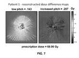
- FIG. 7illustrates slices of variance maps taken between the reconstructed and planned DQA dose grids for both the low and high pitch plans.
- FIG. 8illustrates the results of ion-chamber measurements made both before and after replanning, and indicates a reduction in error with the high pitch plans.
- embodiments of the inventioninclude both hardware, software, and electronic components or modules that, for purposes of discussion, may be illustrated and described as if the majority of the components were implemented solely in hardware.
- the electronic based aspects of the inventionmay be implemented in software.
- a plurality of hardware and software based devices, as well as a plurality of different structural componentsmay be utilized to implement the invention.
- the specific mechanical configurations illustrated in the drawingsare intended to exemplify embodiments of the invention and that other alternative mechanical configurations are possible.
- FIG. 1illustrates a radiation therapy treatment system 10 that can provide radiation therapy to a patient 14 .
- the radiation therapy treatmentcan include photon-based radiation therapy, brachytherapy, electron beam therapy, proton, neutron, or particle therapy, or other types of treatment therapy.
- the radiation therapy treatment system 10includes a gantry 18 .
- the gantry 18can support a radiation module 22 , which can include a radiation source 24 and a linear accelerator 26 operable to generate a beam 30 of radiation.
- the gantry 18 shown in the drawingsis a ring gantry, i.e., it extends through a full 360° arc to create a complete ring or circle, other types of mounting arrangements may also be employed.
- a non-ring-shaped gantrysuch as a C-type, partial ring gantry, or robotic arm could be used. Any other framework capable of positioning the radiation module 22 at various rotational and/or axial positions relative to the patient 14 may also be employed.
- the radiation source 24may travel in path that does not follow the shape of the gantry 18 .
- the radiation source 24may travel in a non-circular path even though the illustrated gantry 18 is generally circular-shaped.
- the radiation module 22can also include a modulation device 34 operable to modify or modulate the radiation beam 30 .
- the modulation device 34provides the modulation of the radiation beam 30 and directs the radiation beam 30 toward the patient 14 .
- the radiation beam 34is directed toward a portion of the patient.
- the portionmay include the entire body, but is generally smaller than the entire body and can be defined by a two-dimensional area and/or a three-dimensional volume.
- a portion desired to receive the radiationwhich may be referred to as a target 38 or target region, is an example of a region of interest.
- Another type of region of interestis a region at risk. If a portion includes a region at risk, the radiation beam is preferably diverted from the region at risk.
- the patient 14may have more than one target region that needs to receive radiation therapy. Such modulation is sometimes referred to as intensity modulated radiation therapy (“IMRT”).
- IMRTintensity modulated radiation therapy
- the modulation device 34can include a collimation device 42 as illustrated in FIG. 2 .
- the collimation device 42includes a set of jaws 46 that define and adjust the size of an aperture 50 through which the radiation beam 30 may pass.
- the jaws 46include an upper jaw 54 and a lower jaw 58 .
- the upper jaw 54 and the lower jaw 58are moveable to adjust the size of the aperture 50 .
- the modulation device 34can comprise a multi-leaf collimator 62 , which includes a plurality of interlaced leaves 66 operable to move from position to position, to provide intensity modulation. It is also noted that the leaves 66 can be moved to a position anywhere between a minimally and maximally-open position. The plurality of interlaced leaves 66 modulate the strength, size, and shape of the radiation beam 30 before the radiation beam 30 reaches the target 38 on the patient 14 .
- Each of the leaves 66is independently controlled by an actuator 70 , such as a motor or an air valve so that the leaf 66 can open and close quickly to permit or block the passage of radiation.
- the actuators 70can be controlled by a computer 74 and/or controller.
- the radiation therapy treatment system 10can also include a detector 78 , e.g., a kilovoltage or a megavoltage detector, operable to receive the radiation beam 30 .
- the linear accelerator 26 and the detector 78can also operate as a computed tomography (CT) system to generate CT images of the patient 14 .
- CTcomputed tomography
- the linear accelerator 26emits the radiation beam 30 toward the target 38 in the patient 14 .
- the target 38absorbs some of the radiation.
- the detector 78detects or measures the amount of radiation absorbed by the target 38 .
- the detector 78collects the absorption data from different angles as the linear accelerator 26 rotates around and emits radiation toward the patient 14 .
- the collected absorption datais transmitted to the computer 74 to process the absorption data and to generate images of the patient's body tissues and organs.
- the imagescan also illustrate bone, soft tissues, and blood vessels.
- the CT imagescan be acquired with a radiation beam 30 that has a fan-shaped geometry, a multi-slice geometry or a cone-beam geometry.
- the CT imagescan be acquired with the linear accelerator 26 delivering megavoltage energies or kilovoltage energies.
- the acquired CT imagescan be registered with previously acquired CT images (from the radiation therapy treatment system 10 or other image acquisition devices, such as other CT scanners, MRI systems, and PET systems).
- the previously acquired CT images for the patient 14can include identified targets 38 made through a contouring process.
- the newly acquired CT images for the patient 14can be registered with the previously acquired CT images to assist in identifying the targets 38 in the new CT images.
- the registration processcan use rigid or deformable registration tools.
- the image datacan be presented on a video display as either a three-dimensional image or a series of two-dimensional images.
- the image data comprising the imagescan be either voxels (for three-dimensional images) or pixels (for two-dimensional images).
- image elementis used generally in the description to refer to both.
- the radiation therapy treatment system 10can include an x-ray source and a CT image detector.
- the x-ray source and the CT image detectoroperate in a similar manner as the linear accelerator 26 and the detector 78 as described above to acquire image data.
- the image datais transmitted to the computer 74 where it is processed to generate images of the patient's body tissues and organs.
- the radiation therapy treatment system 10can also include a patient support, such as a couch 82 (illustrated in FIG. 1 ), which supports the patient 14 .
- the couch 82moves along at least one axis 84 in the x, y, or z directions.
- the patient supportcan be a device that is adapted to support any portion of the patient's body.
- the patient supportis not limited to having to support the entire patient's body.
- the system 10also can include a drive system 86 operable to manipulate the position of the couch 82 .
- the drive system 86can be controlled by the computer 74 .
- the computer 74illustrated in FIGS. 2 and 3 , includes an operating system for running various software programs and/or a communications application.
- the computer 74can include a software program(s) 90 that operates to communicate with the radiation therapy treatment system 10 .
- the computer 74can include any suitable input/output device adapted to be accessed by medical personnel.
- the computer 74can include typical hardware such as a processor, I/O interfaces, and storage devices or memory.
- the computer 74can also include input devices such as a keyboard and a mouse.
- the computer 74can further include standard output devices, such as a monitor.
- the computer 74can include peripherals, such as a printer and a scanner.
- the computer 74can be networked with other computers 74 and radiation therapy treatment systems 10 .
- the other computers 74may include additional and/or different computer programs and software and are not required to be identical to the computer 74 , described herein.
- the computers 74 and radiation therapy treatment system 10can communicate with a network 94 .
- the computers 74 and radiation therapy treatment systems 10can also communicate with a database(s) 98 and a server(s) 102 . It is noted that the software program(s) 90 could also reside on the server(s) 102 .
- the network 94can be built according to any networking technology or topology or combinations of technologies and topologies and can include multiple sub-networks. Connections between the computers and systems shown in FIG. 3 can be made through local area networks (“LANs”), wide area networks (“WANs”), public switched telephone networks (“PSTNs”), wireless networks, Intranets, the Internet, or any other suitable networks. In a hospital or medical care facility, communication between the computers and systems shown in FIG. 3 can be made through the Health Level Seven (“HL7”) protocol or other protocols with any version and/or other required protocol. HL7 is a standard protocol which specifies the implementation of interfaces between two computer applications (sender and receiver) from different vendors for electronic data exchange in health care environments.
- HL7Health Level Seven
- HL7can allow health care institutions to exchange key sets of data from different application systems. Specifically, HL7 can define the data to be exchanged, the timing of the interchange, and the communication of errors to the application.
- the formatsare generally generic in nature and can be configured to meet the needs of the applications involved.
- DICOMDigital Imaging and Communications in Medicine
- the two-way arrows in FIG. 3generally represent two-way communication and information transfer between the network 94 and any one of the computers 74 and the systems 10 shown in FIG. 3 . However, for some medical and computerized equipment, only one-way communication and information transfer may be necessary.
- the software program 90includes a plurality of modules that communicate with one another to perform functions of the radiation therapy treatment process.
- the various modulescommunication with one another to determine if delivery of the radiation therapy treatment plan occurred as intended.
- the software program 90includes a treatment plan module 106 operable to generate a treatment plan for the patient 14 based on data input to the system 10 by medical personnel.
- the datacan include one or more images (e.g., planning images and/or pre-treatment images) of at least a portion of the patient 14 and a fluence map.
- the treatment plan module 106separates the treatment into a plurality of fractions and determines the radiation dose for each fraction or treatment based on the prescription input by medical personnel.
- the treatment plan module 106also determines the radiation dose for the target 38 based on various contours drawn around the target 38 . Multiple targets 38 may be present and included in the same treatment plan.
- the software program 90also includes a patient positioning module 110 operable to position and align the patient 14 with respect to the isocenter of the gantry 18 for a particular treatment fraction. While the patient is on the couch 82 , the patient positioning module 110 acquires an image of the patient 14 and compares the current position of the patient 14 to the position of the patient in a reference image.
- the reference imagecan be a planning image, any pre-treatment image, or a combination of a planning image and a pre-treatment image. If the patient's position needs to be adjusted, the patient positioning module 110 provides instructions to the drive system 86 to move the couch 82 or the patient 14 can be manually moved to the new position.
- the patient positioning module 110can receive data from lasers positioned in the treatment room to provide patient position data with respect to the isocenter of the gantry 18 . Based on the data from the lasers, the patient positioning module 110 provides instructions to the drive system 86 , which moves the couch 82 to achieve proper alignment of the patient 14 with respect to the gantry 18 . It is noted that devices and systems, other than lasers, can be used to provide data to the patient positioning module 110 to assist in the alignment process.
- the patient positioning module 110also is operable to detect and/or monitor patient motion during treatment.
- the patient positioning module 110may communicate with and/or incorporate a motion detection system 112 , such as x-ray, in-room CT, laser positioning devices, camera systems, spirometers, ultrasound, tensile measurements, chest bands, and the like.
- a motion detection system 112such as x-ray, in-room CT, laser positioning devices, camera systems, spirometers, ultrasound, tensile measurements, chest bands, and the like.
- the patient motioncan be irregular or unexpected, and does not need to follow a smooth or reproducible path.
- the software program 90also includes a treatment delivery module 114 operable to instruct the radiation therapy treatment system 10 to deliver the treatment plan to the patient 14 according to the treatment plan.
- the treatment delivery module 114can generate and transmit instructions to the gantry 18 , the linear accelerator 26 , the modulation device 34 , and the drive system 86 to deliver radiation to the patient 14 .
- the instructionscoordinate the necessary movements of the gantry 18 , the modulation device 34 , and the drive system 86 according to a fluence map to deliver the radiation beam 30 to the proper target in the proper amount as specified in the treatment plan.
- the treatment delivery module 114also calculates the appropriate pattern, position, and intensity of the radiation beam 30 to be delivered, to match the prescription as specified by the treatment plan.
- the pattern of the radiation beam 30is generated by the modulation device 34 , and more particularly by movement of the plurality of leaves in the multi-leaf collimator.
- the treatment delivery module 114can utilize canonical, predetermined or template leaf patterns to generate the appropriate pattern for the radiation beam 30 based on the treatment parameters.
- the treatment delivery module 114can also include a library of patterns for typical cases that can be accessed in which to compare the present patient data to determine the pattern for the radiation beam 30 .
- the software program 90also includes a feedback module 118 operable to receive data from the radiation therapy treatment system 10 during a patient treatment.
- the feedback module 118can receive data from the radiation therapy treatment device and can include information related to patient transmission data, ion chamber data, fluence output data, MLC data, system temperatures, component speeds and/or positions, flow rates, etc.
- the feedback module 118can also receive data related to the treatment parameters, amount of radiation dose the patient received, image data acquired during the treatment, and patient movement.
- the feedback module 118can receive input data from a user and/or other sources. The feedback module 118 acquires and stores the data until needed for further processing.
- the software program 90also includes an analysis module 122 operable to analyze the data from the feedback module 118 to determine whether delivery of the treatment plan occurred as intended and to validate that the planned delivery is reasonable based on the newly-acquired data.
- the analysis module 122can also determine, based on the received data and/or additional inputted data, whether a problem has occurred during delivery of the treatment plan. For example, the analysis module 122 can determine if the problem is related to an error of the radiation therapy treatment device 10 , an anatomical error, such as patient movement, and/or a clinical error, such as a data input error.
- the analysis module 122can detect errors in the radiation therapy treatment device 10 related to the couch 82 , the device output, the gantry 18 , the multi-leaf collimator 62 , the patient setup, and timing errors between the components of the radiation therapy treatment device 10 . For example, the analysis module 122 can determine if a couch replacement was performed during planning, if fixation devices were properly used and accounted for during planning, if position and speed is correct during treatment.
- the analysis module 122can determine whether changes or variations occurred in the output parameters of the radiation therapy treatment device 10 . With respect to the gantry 18 , the analysis module 122 can determine if there are errors in the speed and positioning of the gantry 18 . The analysis module 122 can receive data to determine if the multi-leaf collimator 62 is operating properly. For example, the analysis module 122 can determine if the leaves 66 move at the correct times, if any leaves 66 are stuck in place, if leaf timing is properly calibrated, and whether the leaf modulation pattern is correct for any given treatment plan. The analysis module 122 also can validate patient setup, orientation, and position for any given treatment plan. The analysis module 122 also can validate that the timing between the gantry 18 , the couch 62 , the linear accelerator 26 , the leaves 66 are correct.
- the software program 90also includes a dose calculation module 126 operable to generate a variance map that represents a dose uncertainty.
- the dose calculation module 126receives a density image (e.g., a patient CT image), the relative positions and motions of the radiation source (“source”) with respect to the density image (position and motion is referred to as “plan geometry”), and a fluence map describing the fluence incident to a 2-D plane in front of the source at each moment in time. From these inputs (and others, such as machine commissioning) a dose image is calculated. The fluence map over time is replaced by a map of fluence uncertainty, error, or other metric.
- the dose calculation module 126is run as usual, using the fluence uncertainty/error map like it would normally use the fluence map.
- the resulting imagerepresents the uncertainty/error projected into image space, instead of a dose image.
- the dose calculation module 126generates a variance map by replacing the fluence map with the square of the difference between the planned and delivered fluence maps.
- the dose calculation module 126is run using this variance map.
- the resulting imagerepresents the variance in the dose to each image voxel, accumulated over the duration of the delivery.
- the square root of these variance valueswould be the standard deviation of delivered dose versus planned dose to each voxel over the duration of the delivery.
- Uncertainty or error in plan geometry at a particular timecan be represented as uncertainty in the fluence map over a neighboring time interval. For example, if there is uncertainty in the gantry position at some point in time (t), and the gantry is moving, then the fluence uncertainty for a nearby points in time (t′) is affected by the probability that the gantry is at the position expected at that time (t′).
- the variance map generated by the dose calculation module 126illustrates on a point-by-point basis where high uncertainty in the dose may exist and where low uncertainty in the dose may exist.
- the dose uncertaintyis a result of an error in one or more data parameters related to a delivery parameter or a computational parameter.
- the dose uncertaintyrepresents the effect of uncertainties in the planning and delivery of radiation to the patient.
- the dose uncertaintycan be taken into consideration prospectively when planning a treatment plan for the patient and retrospectively to adjust or modify the treatment plan.
- the dose uncertaintyserves as a constraint when determining a setting of the data parameter(s).
- the data parameters related to delivery of radiationcan include linac output, leaf timing, jaw position, spectral changes in attenuation/energy components of a radiation beam, couch position, and gantry position.
- Other data parameters related to modeling effectscan include leaf size, leaf shape, jaw shape, tongue and groove information of two adjacent leaves, a source-to-axis distance, and a change in beam shape.
- the dose calculation module 126can generate a dose variance map reflecting the effect on dose for a single data parameter.
- the dose calculation module 126allows the user to anticipate operation of the radiation delivery device and to incorporate device feedback, which includes the error(s) to modify the treatment plan.
- the dose calculation module 126proactively accounts for mechanical variations of the device and how they may impact the treatment delivery.
- the dose calculation module 126can optimize a treatment plan to reduce the dose uncertainty by using the uncertainty indication to set one or more of the data parameters when preparing for treatment delivery. More specifically, the treatment plan can be optimized to reduce the uncertainty in dose for a particular area in the patient as shown on the dose variance map. In addition, the treatment plan can be modified to account for the dose variance map, a different radiation delivery device can be selected to deliver the treatment, and an entirely different treatment plan can be generated or chosen from a list of alternate plans previously generated.
- the dose calculation module 126also can optimize the treatment plan to reduce dose uncertainty by reducing the treatment plan's dependence on MLC leaves that have higher uncertainty (e.g., if a leaf is starting to go fall out of tolerance, we can generate treatment plans that use it less often), adjusting the treatment plan isocenter to reduce the impact of MLC or jaw positional uncertainties, adjusting the fraction of leaf open time in projections to reduce leaf timing uncertainties—leaf timing uncertainties are larger when a leaf has a very short open time or an open time nearly as long as the projection time, and/or reducing the treatment plan's dependence on gantry angles that have higher machine output uncertainty or shoot through regions of space that are affected by couch top position uncertainty.
- the dose calculation module 126also can evaluate the deliverability of an optimized treatment plan. For example, the dose calculation module 126 can recommend that a different radiation delivery device be used to deliver the treatment plan to the patient. The dose calculation module 126 also can generate an alert to the user when the dose variance map indicates that the uncertainty in dose exceeds a predetermined threshold. The alert can be the basis for a number of decisions by the user, including selecting a different plan, reoptimizing the current plan, adjusting patient position or machine parameters, or performing repairs or maintenance on the delivery device.
- the dose calculator 126can detect a delivery error in the radiation delivery device. To do so, the dose calculator 126 can receive exit data from the radiation delivery device after delivery of the treatment plan.
- the exit data(e.g., output fluence information) can come from a detector such as, for example, a single-row gas ionization detector (e.g., xenon), a multi-row gas ionization detector, a crystal detector, a solid state detector, a flat panel detector (e.g., Amorphous silicon or selenium), or other suitable detecting devices.
- the dose calculator 126can compare an intended fluence, which was specified in the treatment plan, with the output fluence information to generate a fluence variance.
- the dose calculator 126uses the fluence variance as an input to a dose calculation algorithm to generate a dose variance map.
- the dose variance mapcan be displayed to the user.
- the fluence variancecan be based on feedback from the radiation delivery device over the course of a plurality of treatment fractions. Based on the fluence variance, the treatment plan can be modified, a new treatment plan can be generated, and/or a different radiation delivery device may be selected to deliver the remaining treatment fractions.
- the dose calculation module 126also can evaluate a partially delivered treatment plan to determine how pre-treatment variance risk is actually realized by looking at actual variances.
- a treatment planis generated that includes a plurality of treatment fractions and intended variance information. After delivery of at least one of the treatment fractions, the dose calculation module 126 acquires output fluence information from the radiation delivery device.
- the dose calculation module 126can evaluate future treatment fractions and assess the risk of treatment plan deviation for future treatments based upon a combination of the intended variance information and the measured variance information. Based on that risk, the user can decide whether to proceed with the plan, whether to reoptimize the plan, whether to choose a different plan to deliver, or whether other delivery options exist.
- Sinogram analysisshowed increases in mean leaf open-times of 30-85% for the higher pitch plans.
- ion-chamber measurementsshowed a reduction in point dose errors of 1.9-4.4%, bringing the patient plans within the ⁇ 3% acceptance criteria.
- Dose reconstruction resultswere in excellent agreement with ion-chamber measurements and clearly illustrate the impact of leaf timing errors on plans having predominantly small leaf open-times.
- FIG. 5shows dose volume histograms for a representative patient replanned using an increased pitch of 0.287
- FIG. 6shows histograms of the normalized leaf open times both before and after replanning. These figures illustrate that while near equivalent plans are achieved using the two different pitch values, the mean leaf open time is increased by a factor of 1.85 for the increased pitch plan.
- FIG. 7shows slices of difference maps taken between the reconstructed and planned DQA dose grids for both the low and high pitch plans. These difference maps are taken in the plane of the DQA ion-chamber measurements and illustrate the impact of leaf timing errors when treating plans that use predominantly low leaf open-times.
- FIG. 8shows the results of ion-chamber measurements made both before and after replanning, and indicates a reduction in error with the high pitch plans ranging from 1.9-4.4% for the three patients examined. Reconstructed dose values are also included in this figure and show excellent agreement with measured values for all plans delivered.
- one aspect of the inventionincludes a method of transferring that fluence uncertainty into something visual.
- the inventionincludes a method of using dose calculation as a means to visualize uncertainty (i.e., visualize errors in the fluence map by transforming those errors into errors in dose).
- error sourcessuch as MLC errors, linac output variation, delivery uncertainties, gantry motion, beam trajectory through the patient, couch motion, IVDT/density uncertainties, machine calibration parameters, etc.
- dose calculatoruses the dose calculator to combine the errors like dose to make an error or variance map.
- Leaf open timeis one possible error that can be identified and calculated according to this method.
- the methodincludes replacing the fluence map with an uncertainty (error or variance) map and sending the uncertainty indication through the dose calculator to get a dose uncertainty.
- the varianceis distributed in real space (ray tracing from sinogram space into patient space).
- a convolution algorithmcan be applied to the variance and in some embodiments, optimize the plan with respect to the uncertainty indication.
- a treatment plan's sensitivity to delivery or modeling errors in the fluence mapcan be evaluated by generating a variance (or error) map post-delivery throughout the treatment volume.
- this approachcan be usable for investigating any type of delivery or modeling error that can be estimated on a per-beamlet basis.
- One type of potential delivery erroris related to a leaf open-time parameter, which is discussed below.
- Certain treatment planscan be sensitive to short leaf open-time errors.
- one leafwas consistently about 6 ms “hot”.
- a leaf open-time errorgenerally manifests itself as a dose error for treatment plans with predominantly short leaf open-times using (in this case) the “hot” leaf.
- all treatment plans with a significant number of short leaf open-time beamletswill have dose errors.
- the short leaf open-time beamlets (and their associated errors)are distributed throughout the dose volume the effect in any one region may be negligible.
- a treatment plan with relatively small number of short leaf open-time beamletsmight show a significant dose error if many of those beamlets dominate the dose in one location.
- the units of variance supplied to the dose calculatorshould be directly proportional to fluence so the contributions from multiple beamlets can sum like the dose would.
- leaf open-time errorsthat would be time (instead of the unit-less percent LOT error, for example). If a percent-error is desired, that calculation can occur after the error is summed.
Landscapes
- Health & Medical Sciences (AREA)
- Engineering & Computer Science (AREA)
- General Health & Medical Sciences (AREA)
- Nuclear Medicine, Radiotherapy & Molecular Imaging (AREA)
- Public Health (AREA)
- Biomedical Technology (AREA)
- Urology & Nephrology (AREA)
- Surgery (AREA)
- Epidemiology (AREA)
- Medical Informatics (AREA)
- Primary Health Care (AREA)
- Animal Behavior & Ethology (AREA)
- Life Sciences & Earth Sciences (AREA)
- Radiology & Medical Imaging (AREA)
- Veterinary Medicine (AREA)
- Pathology (AREA)
- Radiation-Therapy Devices (AREA)
Abstract
Description
| TABLE 1 |
| Patient plan parameters and DQA measurement data |
| Plan parameters |
| Patient data | Dose/ | Mean | DQA dose errors |
| Disease | fx | fractional | Planned | Discrepancy |
| Patient | site | (Gy) | Pitch | leaf time | dose (Gy) | (%) |
| 1 | Head and | 2.12 | 0.143 | 0.196 | 1.589 | 4.47 |
| 2 | Thorax | 1.80 | 0.215 | 0.304 | 1.448 | 3.59 |
| 3 | Thyroid | 2.00 | 0.215 | 0.285 | 1.391 | 4.96 |
| 4 | Lung | 3.00 | 0.215 | 0.519 | 2.651 | −0.53 |
| 5 | Prostate | 2.50 | 0.172 | 0.448 | 2.877 | −0.48 |
| 6 | Pelvis | 3.00 | 0.215 | 0.472 | 2.487 | −0.16 |
Claims (29)
Priority Applications (2)
| Application Number | Priority Date | Filing Date | Title |
|---|---|---|---|
| US12/550,184US8363784B2 (en) | 2008-08-28 | 2009-08-28 | System and method of calculating dose uncertainty |
| US13/739,590US8913716B2 (en) | 2008-08-28 | 2013-01-11 | System and method of calculating dose uncertainty |
Applications Claiming Priority (2)
| Application Number | Priority Date | Filing Date | Title |
|---|---|---|---|
| US9252308P | 2008-08-28 | 2008-08-28 | |
| US12/550,184US8363784B2 (en) | 2008-08-28 | 2009-08-28 | System and method of calculating dose uncertainty |
Related Child Applications (1)
| Application Number | Title | Priority Date | Filing Date |
|---|---|---|---|
| US13/739,590DivisionUS8913716B2 (en) | 2008-08-28 | 2013-01-11 | System and method of calculating dose uncertainty |
Publications (2)
| Publication Number | Publication Date |
|---|---|
| US20100054413A1 US20100054413A1 (en) | 2010-03-04 |
| US8363784B2true US8363784B2 (en) | 2013-01-29 |
Family
ID=41722324
Family Applications (2)
| Application Number | Title | Priority Date | Filing Date |
|---|---|---|---|
| US12/550,184Active2029-11-23US8363784B2 (en) | 2008-08-28 | 2009-08-28 | System and method of calculating dose uncertainty |
| US13/739,590Active2030-02-05US8913716B2 (en) | 2008-08-28 | 2013-01-11 | System and method of calculating dose uncertainty |
Family Applications After (1)
| Application Number | Title | Priority Date | Filing Date |
|---|---|---|---|
| US13/739,590Active2030-02-05US8913716B2 (en) | 2008-08-28 | 2013-01-11 | System and method of calculating dose uncertainty |
Country Status (5)
| Country | Link |
|---|---|
| US (2) | US8363784B2 (en) |
| EP (1) | EP2319002A2 (en) |
| JP (1) | JP2012501230A (en) |
| CN (1) | CN102138155A (en) |
| WO (1) | WO2010025399A2 (en) |
Cited By (11)
| Publication number | Priority date | Publication date | Assignee | Title |
|---|---|---|---|---|
| US20110019889A1 (en)* | 2009-06-17 | 2011-01-27 | David Thomas Gering | System and method of applying anatomically-constrained deformation |
| US20150097868A1 (en)* | 2012-03-21 | 2015-04-09 | Koninklijkie Philips N.V. | Clinical workstation integrating medical imaging and biopsy data and methods using same |
| US20170087382A1 (en)* | 2015-09-25 | 2017-03-30 | Varian Medical Systems International Ag | Apparatus and method using automatic generation of a base dose |
| US9925391B2 (en) | 2013-06-21 | 2018-03-27 | Siris Medical, Inc. | Multi-objective radiation therapy selection system and method |
| US10293179B2 (en) | 2014-10-31 | 2019-05-21 | Siris Medical, Inc. | Physician directed radiation treatment planning |
| US10709905B2 (en)* | 2018-06-29 | 2020-07-14 | Victor Hernandez | Method of calculating a tongue-and-groove effect of a multi-leaf collimator |
| US11120916B2 (en) | 2018-12-26 | 2021-09-14 | Wipro Limited | Method and a system for managing time-critical events associated with critical devices |
| US11147985B2 (en)* | 2017-02-02 | 2021-10-19 | Koninklijke Philips N.V. | Warm start initialization for external beam radiotherapy plan optimization |
| US20220212037A1 (en)* | 2019-04-22 | 2022-07-07 | Suzhou Linatech Medical Science and Technology Co.,Ltd. | Radiotherapy device and radiotherapy method |
| US11541252B2 (en)* | 2020-06-23 | 2023-01-03 | Varian Medical Systems, Inc. | Defining dose rate for pencil beam scanning |
| US20240123259A1 (en)* | 2021-01-26 | 2024-04-18 | Ardos Aps | System and method for dose guidance and repeated estimation of final delivered radiation dose for a radiotherapy system |
Families Citing this family (52)
| Publication number | Priority date | Publication date | Assignee | Title |
|---|---|---|---|---|
| US8442287B2 (en)* | 2005-07-22 | 2013-05-14 | Tomotherapy Incorporated | Method and system for evaluating quality assurance criteria in delivery of a treatment plan |
| JP5060476B2 (en) | 2005-07-22 | 2012-10-31 | トモセラピー・インコーポレーテッド | System and method for detecting respiratory phase of a patient undergoing radiation therapy |
| CN101267857A (en) | 2005-07-22 | 2008-09-17 | 断层放疗公司 | System and method of delivering radiation therapy to a moving region of interest |
| US20070041496A1 (en)* | 2005-07-22 | 2007-02-22 | Olivera Gustavo H | System and method of remotely analyzing operation of a radiation therapy system |
| US9731148B2 (en) | 2005-07-23 | 2017-08-15 | Tomotherapy Incorporated | Radiation therapy imaging and delivery utilizing coordinated motion of gantry and couch |
| EP1934898A4 (en)* | 2005-10-14 | 2009-10-21 | Tomotherapy Inc | Method and interface for adaptive radiation therapy |
| CN101820948A (en)* | 2007-10-25 | 2010-09-01 | 断层放疗公司 | System and method for motion adaptive optimization of radiotherapy delivery |
| CN101820827A (en) | 2007-10-25 | 2010-09-01 | 断层放疗公司 | The method of the fractionation of radiation dosage of accommodation radiotherapy dosage |
| US8467497B2 (en)* | 2007-10-25 | 2013-06-18 | Tomotherapy Incorporated | System and method for motion adaptive optimization for radiation therapy delivery |
| WO2009111580A2 (en)* | 2008-03-04 | 2009-09-11 | Tomotherapy Incorporated | Method and system for improved image segmentation |
| EP2116277A1 (en) | 2008-05-06 | 2009-11-11 | Ion Beam Applications S.A. | Device and method for particle therapy monitoring and verification |
| EP2116278A1 (en)* | 2008-05-06 | 2009-11-11 | Ion Beam Applications S.A. | Device for 3D dose tracking in radiation therapy |
| US8803910B2 (en) | 2008-08-28 | 2014-08-12 | Tomotherapy Incorporated | System and method of contouring a target area |
| US20100228116A1 (en)* | 2009-03-03 | 2010-09-09 | Weiguo Lu | System and method of optimizing a heterogeneous radiation dose to be delivered to a patient |
| WO2011041412A2 (en)* | 2009-09-29 | 2011-04-07 | Tomotherapy Incorporated | Patient support device with low attenuation properties |
| US8401148B2 (en) | 2009-10-30 | 2013-03-19 | Tomotherapy Incorporated | Non-voxel-based broad-beam (NVBB) algorithm for intensity modulated radiation therapy dose calculation and plan optimization |
| US9087224B2 (en)* | 2010-02-02 | 2015-07-21 | University Health Network | System and method for commissioning of a beam model for a three dimensional radiation therapy treatment planning system |
| DE102011000204B4 (en)* | 2011-01-18 | 2013-04-25 | Gsi Helmholtzzentrum Für Schwerionenforschung Gmbh | Preparation of treatment planning taking into account the effects of at least one uncertainty |
| DE102011083196B4 (en)* | 2011-09-22 | 2014-10-02 | Siemens Aktiengesellschaft | Determination of the duration of irradiation during particle irradiation planning |
| US9314160B2 (en)* | 2011-12-01 | 2016-04-19 | Varian Medical Systems, Inc. | Systems and methods for real-time target validation for image-guided radiation therapy |
| DE102011088160B3 (en)* | 2011-12-09 | 2013-05-16 | Siemens Aktiengesellschaft | Irradiation planning method and irradiation planning device for particle therapy |
| JP2013141574A (en)* | 2012-01-12 | 2013-07-22 | Toshiba Corp | X-ray imaging apparatus and program |
| US20140108026A1 (en)* | 2012-03-15 | 2014-04-17 | Brian Gale | Automatic clinical treatment device usage monitoring |
| CN104837523B (en)* | 2012-12-14 | 2018-09-21 | 伊利克塔股份有限公司 | radiation therapy equipment |
| EP2962309B1 (en) | 2013-02-26 | 2022-02-16 | Accuray, Inc. | Electromagnetically actuated multi-leaf collimator |
| EP2976129B1 (en)* | 2013-03-19 | 2021-09-08 | Koninklijke Philips N.V. | Audio-visual summarization system for rt plan evaluation |
| JP2016525465A (en)* | 2013-06-27 | 2016-08-25 | コーロン インダストリーズ インク | Polyester film and method for producing the same |
| US9764162B1 (en)* | 2013-10-28 | 2017-09-19 | Elekta, Inc. | Automated, data-driven treatment management system for adaptive radiotherapy workflows |
| EP3180084A1 (en) | 2014-08-15 | 2017-06-21 | Koninklijke Philips N.V. | Supervised 4-d dose map deformation for adaptive radiotherapy planning |
| WO2016046683A2 (en) | 2014-09-22 | 2016-03-31 | Koninklijke Philips N.V. | Radiation therapy planning optimization and visualization |
| CN104548372B (en)* | 2015-01-07 | 2017-12-22 | 上海联影医疗科技有限公司 | The dosage determining device of radiotherapy |
| CN104750992B (en) | 2015-04-01 | 2017-11-28 | 上海联影医疗科技有限公司 | Simulation particle transports and determined the method, apparatus and system of human dose in radiotherapy |
| CN107408284B (en)* | 2015-04-07 | 2021-11-16 | 富士胶片株式会社 | Diagnosis and treatment support device, operation method thereof, recording medium, and diagnosis and treatment support system |
| EP3302699A1 (en)* | 2015-05-28 | 2018-04-11 | Koninklijke Philips N.V. | Method of selecting beam geometries |
| WO2017156316A1 (en) | 2016-03-09 | 2017-09-14 | Reflexion Medical, Inc. | Fluence map generation methods for radiotherapy |
| US10912953B2 (en)* | 2016-03-31 | 2021-02-09 | Varian Medical Systems Particle Therapy Gmbh | Adaptive pencil beam scanning |
| EP3228356B1 (en)* | 2016-04-07 | 2018-03-14 | RaySearch Laboratories AB | Method, computer program and system for optimizing a radiotherapy treatment plan |
| WO2017199390A1 (en)* | 2016-05-19 | 2017-11-23 | 三菱電機株式会社 | Dose distribution calculation device and particle beam therapy apparatus provided with dose distribution calculation device |
| US10307614B2 (en)* | 2016-09-22 | 2019-06-04 | Accuray Incorporated | Systems and methods for selecting a radiation therapy treatment plan |
| US10850120B2 (en) | 2016-12-27 | 2020-12-01 | Varian Medical Systems International Ag | Selecting a dose prediction model based on clinical goals |
| US10188873B2 (en)* | 2017-03-22 | 2019-01-29 | Varian Medical Systems International Ag | Systems and methods for dose calculation in generating radiation treatment plans |
| US11058892B2 (en) | 2017-05-05 | 2021-07-13 | Zap Surgical Systems, Inc. | Revolving radiation collimator |
| CN108401421B (en) | 2017-09-06 | 2022-12-20 | 睿谱外科系统股份有限公司 | Self-shielding integrated control radiosurgery system |
| US11147989B2 (en) | 2018-06-20 | 2021-10-19 | Accuray Incorporated | Compensating for target rotation with a collimation system |
| KR102035736B1 (en)* | 2018-07-19 | 2019-10-23 | 연세대학교 산학협력단 | Method and Apparatus for Delivery Quality Assurance of Radiotherapy Equipment |
| WO2020047044A1 (en)* | 2018-08-31 | 2020-03-05 | Mayo Foundation For Medical Education And Research | System and method for robust treatment planning in radiation therapy |
| CN109289129B (en)* | 2018-09-07 | 2020-12-15 | 广州医科大学附属肿瘤医院 | Quality control method and device for linear accelerator |
| US12109438B2 (en)* | 2018-12-26 | 2024-10-08 | Our United Corporation | Positioning method realized by computer, and radiotherapy system |
| US11684446B2 (en) | 2019-02-27 | 2023-06-27 | Zap Surgical Systems, Inc. | Device for radiosurgical treatment of uterine fibroids |
| EP3831448A1 (en)* | 2019-12-02 | 2021-06-09 | Koninklijke Philips N.V. | System, method and computer program for determining a radiation therapy plan for a radiation therapy system |
| JP2024506842A (en) | 2021-02-01 | 2024-02-15 | ザップ サージカル システムズ, インコーポレイテッド | Reverse planning device and method for radiotherapy |
| JP7692282B2 (en)* | 2021-04-21 | 2025-06-13 | 株式会社日立ハイテク | Treatment planning device, particle beam therapy system, treatment plan generation method, and computer program |
Citations (103)
| Publication number | Priority date | Publication date | Assignee | Title |
|---|---|---|---|---|
| US4149081A (en) | 1976-11-29 | 1979-04-10 | Varian Associates, Inc. | Removal of spectral artifacts and utilization of spectral effects in computerized tomography |
| US4455609A (en) | 1980-09-17 | 1984-06-19 | Nippon Electric Co., Ltd. | Apparatus for realtime fast reconstruction and display of dose distribution |
| US4998268A (en) | 1989-02-09 | 1991-03-05 | James Winter | Apparatus and method for therapeutically irradiating a chosen area using a diagnostic computer tomography scanner |
| US5008907A (en) | 1989-05-31 | 1991-04-16 | The Regents Of The University Of California | Therapy x-ray scanner |
| US5027818A (en) | 1987-12-03 | 1991-07-02 | University Of Florida | Dosimetric technique for stereotactic radiosurgery same |
| US5044354A (en) | 1989-06-30 | 1991-09-03 | Siemens Aktiengesellschaft | Apparatus for treating a life form with focussed shockwaves |
| US5065315A (en) | 1989-10-24 | 1991-11-12 | Garcia Angela M | System and method for scheduling and reporting patient related services including prioritizing services |
| US5117829A (en) | 1989-03-31 | 1992-06-02 | Loma Linda University Medical Center | Patient alignment system and procedure for radiation treatment |
| US5317616A (en) | 1992-03-19 | 1994-05-31 | Wisconsin Alumni Research Foundation | Method and apparatus for radiation therapy |
| US5332908A (en) | 1992-03-31 | 1994-07-26 | Siemens Medical Laboratories, Inc. | Method for dynamic beam profile generation |
| US5335255A (en) | 1992-03-24 | 1994-08-02 | Seppi Edward J | X-ray scanner with a source emitting plurality of fan beams |
| US5351280A (en) | 1992-03-19 | 1994-09-27 | Wisconsin Alumni Research Foundation | Multi-leaf radiation attenuator for radiation therapy |
| US5391139A (en) | 1992-09-03 | 1995-02-21 | William Beaumont Hospital | Real time radiation treatment planning system |
| US5405309A (en) | 1993-04-28 | 1995-04-11 | Theragenics Corporation | X-ray emitting interstitial implants |
| US5446548A (en) | 1993-10-08 | 1995-08-29 | Siemens Medical Systems, Inc. | Patient positioning and monitoring system |
| US5471516A (en) | 1994-10-06 | 1995-11-28 | Varian Associates, Inc. | Radiotherapy apparatus equipped with low dose localizing and portal imaging X-ray source |
| US5511549A (en) | 1995-02-13 | 1996-04-30 | Loma Linda Medical Center | Normalizing and calibrating therapeutic radiation delivery systems |
| US5552605A (en) | 1994-11-18 | 1996-09-03 | Picker International, Inc. | Motion correction based on reprojection data |
| US5579358A (en) | 1995-05-26 | 1996-11-26 | General Electric Company | Compensation for movement in computed tomography equipment |
| US5596653A (en) | 1991-04-09 | 1997-01-21 | Mitsubishi Denki Kabushiki Kaisha | Radiation therapy treatment planning system |
| US5596619A (en) | 1992-08-21 | 1997-01-21 | Nomos Corporation | Method and apparatus for conformal radiation therapy |
| US5621779A (en) | 1995-07-20 | 1997-04-15 | Siemens Medical Systems, Inc. | Apparatus and method for delivering radiation to an object and for displaying delivered radiation |
| US5622187A (en) | 1994-09-30 | 1997-04-22 | Nomos Corporation | Method and apparatus for patient positioning for radiation therapy |
| US5625663A (en) | 1992-03-19 | 1997-04-29 | Wisconsin Alumni Research Foundation | Dynamic beam flattening apparatus for radiation therapy |
| US5647663A (en) | 1996-01-05 | 1997-07-15 | Wisconsin Alumni Research Foundation | Radiation treatment planning method and apparatus |
| US5651043A (en) | 1994-03-25 | 1997-07-22 | Kabushiki Kaisha Toshiba | Radiotherapy system |
| US5661773A (en) | 1992-03-19 | 1997-08-26 | Wisconsin Alumni Research Foundation | Interface for radiation therapy machine |
| US5668371A (en) | 1995-06-06 | 1997-09-16 | Wisconsin Alumni Research Foundation | Method and apparatus for proton therapy |
| US5673300A (en) | 1996-06-11 | 1997-09-30 | Wisconsin Alumni Research Foundation | Method of registering a radiation treatment plan to a patient |
| US5692507A (en) | 1990-07-02 | 1997-12-02 | Varian Associates, Inc. | Computer tomography apparatus using image intensifier detector |
| US5712482A (en) | 1996-08-05 | 1998-01-27 | Physics Technology, Inc. | Portable electronic radiographic imaging apparatus |
| US5724400A (en) | 1992-03-19 | 1998-03-03 | Wisconsin Alumni Research Foundation | Radiation therapy system with constrained rotational freedom |
| US5751781A (en) | 1995-10-07 | 1998-05-12 | Elekta Ab | Apparatus for treating a patient |
| US5754622A (en) | 1995-07-20 | 1998-05-19 | Siemens Medical Systems, Inc. | System and method for verifying the amount of radiation delivered to an object |
| US5760395A (en) | 1996-04-18 | 1998-06-02 | Universities Research Assoc., Inc. | Method and apparatus for laser-controlled proton beam radiology |
| US5818902A (en) | 1996-03-01 | 1998-10-06 | Elekta Ab | Intensity modulated arc therapy with dynamic multi-leaf collimation |
| US5823192A (en) | 1996-07-31 | 1998-10-20 | University Of Pittsburgh Of The Commonwealth System Of Higher Education | Apparatus for automatically positioning a patient for treatment/diagnoses |
| US5835562A (en) | 1993-11-22 | 1998-11-10 | Hologic, Inc. | Medical radiological apparatus including optical crosshair device for patient positioning and forearm and spinal positioning aides |
| US5870697A (en) | 1996-03-05 | 1999-02-09 | The Regents Of The University Of California | Calculation of radiation therapy dose using all particle Monte Carlo transport |
| US5986274A (en) | 1997-02-07 | 1999-11-16 | Hitachi, Ltd. | Charged particle irradiation apparatus and an operating method thereof |
| US6038283A (en) | 1996-10-24 | 2000-03-14 | Nomos Corporation | Planning method and apparatus for radiation dosimetry |
| US6222905B1 (en) | 1998-08-27 | 2001-04-24 | Mitsubishi Denki Kabushiki Kaisha | Irradiation dose calculation unit, irradiation dose calculation method and recording medium |
| US6241670B1 (en) | 1997-07-02 | 2001-06-05 | Kabushiki Kaisha Toshiba | Radiotherapy system |
| US6301329B1 (en) | 1998-02-09 | 2001-10-09 | The University Of Southampton | Treatment planning method and apparatus for radiation therapy |
| US6345114B1 (en) | 1995-06-14 | 2002-02-05 | Wisconsin Alumni Research Foundation | Method and apparatus for calibration of radiation therapy equipment and verification of radiation treatment |
| US6385288B1 (en) | 2001-01-19 | 2002-05-07 | Mitsubishi Denki Kabushiki Kaisha | Radiotherapy apparatus with independent rotation mechanisms |
| US6393096B1 (en) | 1998-05-27 | 2002-05-21 | Nomos Corporation | Planning method and apparatus for radiation dosimetry |
| US6438202B1 (en) | 1998-08-06 | 2002-08-20 | Wisconsin Alumni Research Foundation | Method using post-patient radiation monitor to verify entrance radiation and dose in a radiation therapy machine |
| US6473490B1 (en) | 2001-09-28 | 2002-10-29 | Siemens Medical Solutions Usa, Inc. | Intensity map reconstruction for radiation therapy with a modulating multi-leaf collimator |
| US6477229B1 (en) | 2000-05-12 | 2002-11-05 | Siemens Medical Solutions Usa, Inc. | Radiation therapy planning |
| US6535837B1 (en) | 1999-03-08 | 2003-03-18 | The Regents Of The University Of California | Correlated histogram representation of Monte Carlo derived medical accelerator photon-output phase space |
| US6636622B2 (en) | 1997-10-15 | 2003-10-21 | Wisconsin Alumni Research Foundation | Method and apparatus for calibration of radiation therapy equipment and verification of radiation treatment |
| US20030212325A1 (en) | 2002-03-12 | 2003-11-13 | Cristian Cotrutz | Method for determining a dose distribution in radiation therapy |
| US6661870B2 (en) | 2001-03-09 | 2003-12-09 | Tomotherapy Incorporated | Fluence adjustment for improving delivery to voxels without reoptimization |
| US6697452B2 (en) | 2001-02-16 | 2004-02-24 | The Board Of Trustees Of The Leland Stanford Junior University | Verification method of monitor units and fluence map in intensity modulated radiation therapy |
| US6714620B2 (en) | 2000-09-22 | 2004-03-30 | Numerix, Llc | Radiation therapy treatment method |
| US20040068182A1 (en) | 2002-09-18 | 2004-04-08 | Misra Satrajit Chandra | Digitally reconstruced portal image and radiation therapy workflow incorporating the same |
| US6741674B2 (en) | 1999-11-05 | 2004-05-25 | Georgia Tech Research Corporation | Systems and methods for global optimization of treatment planning for external beam radiation therapy |
| JP2004166975A (en) | 2002-11-20 | 2004-06-17 | Mitsubishi Heavy Ind Ltd | Radiotherapy system, and operation method therefor |
| US6757355B1 (en) | 2000-08-17 | 2004-06-29 | Siemens Medical Solutions Usa, Inc. | High definition radiation treatment with an intensity modulating multi-leaf collimator |
| US20040165696A1 (en)* | 1999-11-05 | 2004-08-26 | Lee Eva K. | Systems and methods for global optimization of treatment planning for external beam radiation therapy |
| US6792073B2 (en) | 2000-05-05 | 2004-09-14 | Washington University | Method and apparatus for radiotherapy treatment planning |
| US6853702B2 (en) | 2000-12-15 | 2005-02-08 | Wendel Dean Renner | Radiation therapy dosimetry quality control process |
| US6873123B2 (en) | 2001-06-08 | 2005-03-29 | Ion Beam Applications S.A. | Device and method for regulating intensity of beam extracted from a particle accelerator |
| US6882702B2 (en) | 2002-04-29 | 2005-04-19 | University Of Miami | Intensity modulated radiotherapy inverse planning algorithm |
| US20050096515A1 (en) | 2003-10-23 | 2005-05-05 | Geng Z. J. | Three-dimensional surface image guided adaptive therapy system |
| US6891178B2 (en) | 2001-07-19 | 2005-05-10 | The Board Of Trustees Of The Lealand Stanford Junior University | Method for checking positional accuracy of the leaves of a multileaf collimator |
| US20050123098A1 (en)* | 2003-08-11 | 2005-06-09 | Wang Duan Q. | Method and apparatus for optimization of collimator angles in intensity modulated radiation therapy treatment |
| US6907282B2 (en) | 2001-11-09 | 2005-06-14 | Siemens Medical Solutions Usa, Inc. | Intensity map resampling for multi-leaf collimator compatibility |
| WO2005057463A1 (en) | 2003-12-12 | 2005-06-23 | The University Of Western Ontario | Method and system for optimizing dose delivery of radiation |
| US20050143965A1 (en) | 2003-03-14 | 2005-06-30 | Failla Gregory A. | Deterministic computation of radiation doses delivered to tissues and organs of a living organism |
| JP2005518908A (en) | 2002-03-06 | 2005-06-30 | トモセラピー インコーポレイテッド | Methods for modifying the delivery of radiation therapy treatments |
| KR20050073862A (en) | 2004-01-12 | 2005-07-18 | 학교법인 고황재단 | The calibration system of radiation absorbed dose using internet |
| US20050197564A1 (en) | 2004-02-20 | 2005-09-08 | University Of Florida Research Foundation, Inc. | System for delivering conformal radiation therapy while simultaneously imaging soft tissue |
| US20050254623A1 (en)* | 2004-04-08 | 2005-11-17 | Srijit Kamath | Field splitting for intensity modulated fields of large size |
| US6984835B2 (en) | 2003-04-23 | 2006-01-10 | Mitsubishi Denki Kabushiki Kaisha | Irradiation apparatus and irradiation method |
| US20060285640A1 (en) | 2005-06-16 | 2006-12-21 | Nomos Corporation | Variance reduction simulation system, program product, and related methods |
| US20070003011A1 (en)* | 2004-06-21 | 2007-01-04 | Lane Derek G | Fast gradient-histogram inverse planning technique for radiation treatment |
| US20070041496A1 (en) | 2005-07-22 | 2007-02-22 | Olivera Gustavo H | System and method of remotely analyzing operation of a radiation therapy system |
| US20070127790A1 (en) | 2005-11-14 | 2007-06-07 | General Electric Company | System and method for anatomy labeling on a PACS |
| US7257196B2 (en) | 2001-02-27 | 2007-08-14 | Kevin John Brown | Radiotherapeutic apparatus |
| US20070197908A1 (en) | 2003-10-29 | 2007-08-23 | Ruchala Kenneth J | System and method for calibrating and positioning a radiation therapy treatment table |
| US20080002809A1 (en) | 2006-06-28 | 2008-01-03 | Mohan Bodduluri | Parallel stereovision geometry in image-guided radiosurgery |
| US20080002811A1 (en) | 2006-06-29 | 2008-01-03 | Allison John W | Treatment delivery optimization |
| US20080008291A1 (en) | 2006-07-06 | 2008-01-10 | Varian Medical Systems International Ag | Spatially-variant normal tissue objective for radiotherapy |
| US20080031406A1 (en) | 2006-05-25 | 2008-02-07 | Di Yan | Real-time, on-line and offline treatment dose tracking and feedback process for volumetric image guided adaptive radiotherapy |
| US20080049896A1 (en) | 2006-08-25 | 2008-02-28 | Kuduvalli Gopinath R | Determining a target-to-surface distance and using it for real time absorbed dose calculation and compensation |
| US7367955B2 (en) | 2003-06-13 | 2008-05-06 | Wisconsin Alumni Research Foundation | Combined laser spirometer motion tracking system for radiotherapy |
| US7391026B2 (en) | 2001-10-22 | 2008-06-24 | Fraunhofer-Gesellschaft Zur Foerderung Der Angewandten Forschung E.V. | Preparation of a selection of control variables for a dose distribution to be adjusted in a technical appliance |
| US20080193006A1 (en) | 2007-02-09 | 2008-08-14 | Udupa Jayaram K | User-Steered 3D Image Segmentation Methods |
| US7450687B2 (en) | 2005-09-29 | 2008-11-11 | University Of Medicine And Dentistry Of New Jersey | Method for verification of intensity modulated radiation therapy |
| US20080279328A1 (en) | 2005-11-18 | 2008-11-13 | Koninklijke Philips Electronics N.V. | Systems and Methods Using X-Ray Tube Spectra For Computed Tomography Applications |
| US7492858B2 (en) | 2005-05-20 | 2009-02-17 | Varian Medical Systems, Inc. | System and method for imaging and treatment of tumorous tissue in breasts using computed tomography and radiotherapy |
| US7519150B2 (en) | 2006-07-26 | 2009-04-14 | Best Medical International, Inc. | System for enhancing intensity modulated radiation therapy, program product, and related methods |
| US7639854B2 (en) | 2005-07-22 | 2009-12-29 | Tomotherapy Incorporated | Method and system for processing data relating to a radiation therapy treatment plan |
| US7639853B2 (en) | 2005-07-22 | 2009-12-29 | Tomotherapy Incorporated | Method of and system for predicting dose delivery |
| US7643661B2 (en) | 2005-07-22 | 2010-01-05 | Tomo Therapy Incorporated | Method and system for evaluating delivered dose |
| US20100053208A1 (en) | 2008-08-28 | 2010-03-04 | Tomotherapy Incorporated | System and method of contouring a target area |
| US7773788B2 (en) | 2005-07-22 | 2010-08-10 | Tomotherapy Incorporated | Method and system for evaluating quality assurance criteria in delivery of a treatment plan |
| US20110019889A1 (en) | 2009-06-17 | 2011-01-27 | David Thomas Gering | System and method of applying anatomically-constrained deformation |
| US20110112351A1 (en) | 2005-07-22 | 2011-05-12 | Fordyce Ii Gerald D | Method and system for evaluating quality assurance criteria in delivery of a treatment plan |
| US7945022B2 (en) | 2008-03-12 | 2011-05-17 | Sun Nuclear Corp. | Radiation therapy plan dose perturbation system and method |
| US8085899B2 (en) | 2007-12-12 | 2011-12-27 | Varian Medical Systems International Ag | Treatment planning system and method for radiotherapy |
Family Cites Families (10)
| Publication number | Priority date | Publication date | Assignee | Title |
|---|---|---|---|---|
| US6240161B1 (en) | 1997-09-25 | 2001-05-29 | Siemens Medical Systems, Inc. | Multi-leaf collimator constrained optimization of intensity modulated treatments |
| EP1238684B1 (en)* | 2001-03-05 | 2004-03-17 | BrainLAB AG | Method for creating or updating a radiation treatment plan |
| US20030072411A1 (en)* | 2001-10-17 | 2003-04-17 | Welsh Donald E. | Beam parameter display on console screen |
| CN1742275A (en)* | 2002-12-19 | 2006-03-01 | 皇家飞利浦电子股份有限公司 | Method and apparatus for selecting operating parameters for a medical imaging system |
| JP2004275636A (en) | 2003-03-19 | 2004-10-07 | Nakano Syst:Kk | Radiation treatment planning device |
| ATE408198T1 (en) | 2003-09-29 | 2008-09-15 | Koninkl Philips Electronics Nv | METHOD AND DEVICE FOR PLANNING RADIATION THERAPY |
| US7831289B2 (en)* | 2003-10-07 | 2010-11-09 | Best Medical International, Inc. | Planning system, method and apparatus for conformal radiation therapy |
| US7400755B2 (en) | 2005-06-02 | 2008-07-15 | Accuray Incorporated | Inverse planning using optimization constraints derived from image intensity |
| US7801349B2 (en) | 2005-06-20 | 2010-09-21 | Accuray Incorporated | Automatic generation of an envelope of constraint points for inverse planning |
| CN101820827A (en)* | 2007-10-25 | 2010-09-01 | 断层放疗公司 | The method of the fractionation of radiation dosage of accommodation radiotherapy dosage |
- 2009
- 2009-08-28WOPCT/US2009/055419patent/WO2010025399A2/enactiveApplication Filing
- 2009-08-28JPJP2011525246Apatent/JP2012501230A/ennot_activeWithdrawn
- 2009-08-28EPEP09810680Apatent/EP2319002A2/ennot_activeWithdrawn
- 2009-08-28CNCN2009801339320Apatent/CN102138155A/enactivePending
- 2009-08-28USUS12/550,184patent/US8363784B2/enactiveActive
- 2013
- 2013-01-11USUS13/739,590patent/US8913716B2/enactiveActive
Patent Citations (114)
| Publication number | Priority date | Publication date | Assignee | Title |
|---|---|---|---|---|
| US4149081A (en) | 1976-11-29 | 1979-04-10 | Varian Associates, Inc. | Removal of spectral artifacts and utilization of spectral effects in computerized tomography |
| US4455609A (en) | 1980-09-17 | 1984-06-19 | Nippon Electric Co., Ltd. | Apparatus for realtime fast reconstruction and display of dose distribution |
| US5027818A (en) | 1987-12-03 | 1991-07-02 | University Of Florida | Dosimetric technique for stereotactic radiosurgery same |
| US4998268A (en) | 1989-02-09 | 1991-03-05 | James Winter | Apparatus and method for therapeutically irradiating a chosen area using a diagnostic computer tomography scanner |
| US5117829A (en) | 1989-03-31 | 1992-06-02 | Loma Linda University Medical Center | Patient alignment system and procedure for radiation treatment |
| US5008907A (en) | 1989-05-31 | 1991-04-16 | The Regents Of The University Of California | Therapy x-ray scanner |
| US5044354A (en) | 1989-06-30 | 1991-09-03 | Siemens Aktiengesellschaft | Apparatus for treating a life form with focussed shockwaves |
| US5065315A (en) | 1989-10-24 | 1991-11-12 | Garcia Angela M | System and method for scheduling and reporting patient related services including prioritizing services |
| US5692507A (en) | 1990-07-02 | 1997-12-02 | Varian Associates, Inc. | Computer tomography apparatus using image intensifier detector |
| US5596653A (en) | 1991-04-09 | 1997-01-21 | Mitsubishi Denki Kabushiki Kaisha | Radiation therapy treatment planning system |
| US5661773A (en) | 1992-03-19 | 1997-08-26 | Wisconsin Alumni Research Foundation | Interface for radiation therapy machine |
| US5351280A (en) | 1992-03-19 | 1994-09-27 | Wisconsin Alumni Research Foundation | Multi-leaf radiation attenuator for radiation therapy |
| US5317616A (en) | 1992-03-19 | 1994-05-31 | Wisconsin Alumni Research Foundation | Method and apparatus for radiation therapy |
| US5394452A (en) | 1992-03-19 | 1995-02-28 | Wisconsin Alumni Research Foundation | Verification system for radiation therapy |
| US5442675A (en) | 1992-03-19 | 1995-08-15 | Wisconsin Alumni Research Foundation | Dynamic collimator for radiation therapy |
| CA2091275C (en) | 1992-03-19 | 2003-01-07 | Stuart Swerdloff | Method and apparatus for radiation therapy |
| US5625663A (en) | 1992-03-19 | 1997-04-29 | Wisconsin Alumni Research Foundation | Dynamic beam flattening apparatus for radiation therapy |
| US5528650A (en) | 1992-03-19 | 1996-06-18 | Swerdloff; Stuart | Method and apparatus for radiation therapy |
| US5548627A (en) | 1992-03-19 | 1996-08-20 | Wisconsin Alumni Research Foundation | Radiation therapy system with constrained rotational freedom |
| US5724400A (en) | 1992-03-19 | 1998-03-03 | Wisconsin Alumni Research Foundation | Radiation therapy system with constrained rotational freedom |
| US5335255A (en) | 1992-03-24 | 1994-08-02 | Seppi Edward J | X-ray scanner with a source emitting plurality of fan beams |
| US5332908A (en) | 1992-03-31 | 1994-07-26 | Siemens Medical Laboratories, Inc. | Method for dynamic beam profile generation |
| US5596619A (en) | 1992-08-21 | 1997-01-21 | Nomos Corporation | Method and apparatus for conformal radiation therapy |
| US5391139A (en) | 1992-09-03 | 1995-02-21 | William Beaumont Hospital | Real time radiation treatment planning system |
| US5405309A (en) | 1993-04-28 | 1995-04-11 | Theragenics Corporation | X-ray emitting interstitial implants |
| US5446548A (en) | 1993-10-08 | 1995-08-29 | Siemens Medical Systems, Inc. | Patient positioning and monitoring system |
| US5835562A (en) | 1993-11-22 | 1998-11-10 | Hologic, Inc. | Medical radiological apparatus including optical crosshair device for patient positioning and forearm and spinal positioning aides |
| US5651043A (en) | 1994-03-25 | 1997-07-22 | Kabushiki Kaisha Toshiba | Radiotherapy system |
| US5754623A (en) | 1994-03-25 | 1998-05-19 | Kabushiki Kaisha Toshiba | Radiotherapy system |
| US5802136A (en) | 1994-05-17 | 1998-09-01 | Nomos Corporation | Method and apparatus for conformal radiation therapy |
| US5622187A (en) | 1994-09-30 | 1997-04-22 | Nomos Corporation | Method and apparatus for patient positioning for radiation therapy |
| US5471516A (en) | 1994-10-06 | 1995-11-28 | Varian Associates, Inc. | Radiotherapy apparatus equipped with low dose localizing and portal imaging X-ray source |
| US5552605A (en) | 1994-11-18 | 1996-09-03 | Picker International, Inc. | Motion correction based on reprojection data |
| US5511549A (en) | 1995-02-13 | 1996-04-30 | Loma Linda Medical Center | Normalizing and calibrating therapeutic radiation delivery systems |
| TW300853B (en) | 1995-02-13 | 1997-03-21 | Univ Loma Linda Med | |
| US5579358A (en) | 1995-05-26 | 1996-11-26 | General Electric Company | Compensation for movement in computed tomography equipment |
| US5668371A (en) | 1995-06-06 | 1997-09-16 | Wisconsin Alumni Research Foundation | Method and apparatus for proton therapy |
| US6345114B1 (en) | 1995-06-14 | 2002-02-05 | Wisconsin Alumni Research Foundation | Method and apparatus for calibration of radiation therapy equipment and verification of radiation treatment |
| US5621779A (en) | 1995-07-20 | 1997-04-15 | Siemens Medical Systems, Inc. | Apparatus and method for delivering radiation to an object and for displaying delivered radiation |
| US5754622A (en) | 1995-07-20 | 1998-05-19 | Siemens Medical Systems, Inc. | System and method for verifying the amount of radiation delivered to an object |
| US5751781A (en) | 1995-10-07 | 1998-05-12 | Elekta Ab | Apparatus for treating a patient |
| US5647663A (en) | 1996-01-05 | 1997-07-15 | Wisconsin Alumni Research Foundation | Radiation treatment planning method and apparatus |
| US5818902A (en) | 1996-03-01 | 1998-10-06 | Elekta Ab | Intensity modulated arc therapy with dynamic multi-leaf collimation |
| US5870697A (en) | 1996-03-05 | 1999-02-09 | The Regents Of The University Of California | Calculation of radiation therapy dose using all particle Monte Carlo transport |
| US5760395A (en) | 1996-04-18 | 1998-06-02 | Universities Research Assoc., Inc. | Method and apparatus for laser-controlled proton beam radiology |
| US5673300A (en) | 1996-06-11 | 1997-09-30 | Wisconsin Alumni Research Foundation | Method of registering a radiation treatment plan to a patient |
| US5823192A (en) | 1996-07-31 | 1998-10-20 | University Of Pittsburgh Of The Commonwealth System Of Higher Education | Apparatus for automatically positioning a patient for treatment/diagnoses |
| US5712482A (en) | 1996-08-05 | 1998-01-27 | Physics Technology, Inc. | Portable electronic radiographic imaging apparatus |
| US6038283A (en) | 1996-10-24 | 2000-03-14 | Nomos Corporation | Planning method and apparatus for radiation dosimetry |
| US5986274A (en) | 1997-02-07 | 1999-11-16 | Hitachi, Ltd. | Charged particle irradiation apparatus and an operating method thereof |
| US6241670B1 (en) | 1997-07-02 | 2001-06-05 | Kabushiki Kaisha Toshiba | Radiotherapy system |
| US6636622B2 (en) | 1997-10-15 | 2003-10-21 | Wisconsin Alumni Research Foundation | Method and apparatus for calibration of radiation therapy equipment and verification of radiation treatment |
| US6301329B1 (en) | 1998-02-09 | 2001-10-09 | The University Of Southampton | Treatment planning method and apparatus for radiation therapy |
| US6393096B1 (en) | 1998-05-27 | 2002-05-21 | Nomos Corporation | Planning method and apparatus for radiation dosimetry |
| US6438202B1 (en) | 1998-08-06 | 2002-08-20 | Wisconsin Alumni Research Foundation | Method using post-patient radiation monitor to verify entrance radiation and dose in a radiation therapy machine |
| US6222905B1 (en) | 1998-08-27 | 2001-04-24 | Mitsubishi Denki Kabushiki Kaisha | Irradiation dose calculation unit, irradiation dose calculation method and recording medium |
| US6535837B1 (en) | 1999-03-08 | 2003-03-18 | The Regents Of The University Of California | Correlated histogram representation of Monte Carlo derived medical accelerator photon-output phase space |
| US20040165696A1 (en)* | 1999-11-05 | 2004-08-26 | Lee Eva K. | Systems and methods for global optimization of treatment planning for external beam radiation therapy |
| US6741674B2 (en) | 1999-11-05 | 2004-05-25 | Georgia Tech Research Corporation | Systems and methods for global optimization of treatment planning for external beam radiation therapy |
| US6792073B2 (en) | 2000-05-05 | 2004-09-14 | Washington University | Method and apparatus for radiotherapy treatment planning |
| US6477229B1 (en) | 2000-05-12 | 2002-11-05 | Siemens Medical Solutions Usa, Inc. | Radiation therapy planning |
| US6757355B1 (en) | 2000-08-17 | 2004-06-29 | Siemens Medical Solutions Usa, Inc. | High definition radiation treatment with an intensity modulating multi-leaf collimator |
| US6714620B2 (en) | 2000-09-22 | 2004-03-30 | Numerix, Llc | Radiation therapy treatment method |
| US6853702B2 (en) | 2000-12-15 | 2005-02-08 | Wendel Dean Renner | Radiation therapy dosimetry quality control process |
| US6385288B1 (en) | 2001-01-19 | 2002-05-07 | Mitsubishi Denki Kabushiki Kaisha | Radiotherapy apparatus with independent rotation mechanisms |
| US6697452B2 (en) | 2001-02-16 | 2004-02-24 | The Board Of Trustees Of The Leland Stanford Junior University | Verification method of monitor units and fluence map in intensity modulated radiation therapy |
| US7257196B2 (en) | 2001-02-27 | 2007-08-14 | Kevin John Brown | Radiotherapeutic apparatus |
| US6661870B2 (en) | 2001-03-09 | 2003-12-09 | Tomotherapy Incorporated | Fluence adjustment for improving delivery to voxels without reoptimization |
| US6873123B2 (en) | 2001-06-08 | 2005-03-29 | Ion Beam Applications S.A. | Device and method for regulating intensity of beam extracted from a particle accelerator |
| US6891178B2 (en) | 2001-07-19 | 2005-05-10 | The Board Of Trustees Of The Lealand Stanford Junior University | Method for checking positional accuracy of the leaves of a multileaf collimator |
| US6473490B1 (en) | 2001-09-28 | 2002-10-29 | Siemens Medical Solutions Usa, Inc. | Intensity map reconstruction for radiation therapy with a modulating multi-leaf collimator |
| US7391026B2 (en) | 2001-10-22 | 2008-06-24 | Fraunhofer-Gesellschaft Zur Foerderung Der Angewandten Forschung E.V. | Preparation of a selection of control variables for a dose distribution to be adjusted in a technical appliance |
| US6907282B2 (en) | 2001-11-09 | 2005-06-14 | Siemens Medical Solutions Usa, Inc. | Intensity map resampling for multi-leaf collimator compatibility |
| JP2005518908A (en) | 2002-03-06 | 2005-06-30 | トモセラピー インコーポレイテッド | Methods for modifying the delivery of radiation therapy treatments |
| US20050201516A1 (en) | 2002-03-06 | 2005-09-15 | Ruchala Kenneth J. | Method for modification of radiotherapy treatment delivery |
| US20030212325A1 (en) | 2002-03-12 | 2003-11-13 | Cristian Cotrutz | Method for determining a dose distribution in radiation therapy |
| US6882702B2 (en) | 2002-04-29 | 2005-04-19 | University Of Miami | Intensity modulated radiotherapy inverse planning algorithm |
| US20040068182A1 (en) | 2002-09-18 | 2004-04-08 | Misra Satrajit Chandra | Digitally reconstruced portal image and radiation therapy workflow incorporating the same |
| JP2004166975A (en) | 2002-11-20 | 2004-06-17 | Mitsubishi Heavy Ind Ltd | Radiotherapy system, and operation method therefor |
| US20050143965A1 (en) | 2003-03-14 | 2005-06-30 | Failla Gregory A. | Deterministic computation of radiation doses delivered to tissues and organs of a living organism |
| US6984835B2 (en) | 2003-04-23 | 2006-01-10 | Mitsubishi Denki Kabushiki Kaisha | Irradiation apparatus and irradiation method |
| US7367955B2 (en) | 2003-06-13 | 2008-05-06 | Wisconsin Alumni Research Foundation | Combined laser spirometer motion tracking system for radiotherapy |
| US20050123098A1 (en)* | 2003-08-11 | 2005-06-09 | Wang Duan Q. | Method and apparatus for optimization of collimator angles in intensity modulated radiation therapy treatment |
| US20050096515A1 (en) | 2003-10-23 | 2005-05-05 | Geng Z. J. | Three-dimensional surface image guided adaptive therapy system |
| US20070197908A1 (en) | 2003-10-29 | 2007-08-23 | Ruchala Kenneth J | System and method for calibrating and positioning a radiation therapy treatment table |
| WO2005057463A1 (en) | 2003-12-12 | 2005-06-23 | The University Of Western Ontario | Method and system for optimizing dose delivery of radiation |
| US7496173B2 (en) | 2003-12-12 | 2009-02-24 | University Of Western Ontario | Method and system for optimizing dose delivery of radiation |
| KR20050073862A (en) | 2004-01-12 | 2005-07-18 | 학교법인 고황재단 | The calibration system of radiation absorbed dose using internet |
| US20050197564A1 (en) | 2004-02-20 | 2005-09-08 | University Of Florida Research Foundation, Inc. | System for delivering conformal radiation therapy while simultaneously imaging soft tissue |
| US20050254623A1 (en)* | 2004-04-08 | 2005-11-17 | Srijit Kamath | Field splitting for intensity modulated fields of large size |
| US20070003011A1 (en)* | 2004-06-21 | 2007-01-04 | Lane Derek G | Fast gradient-histogram inverse planning technique for radiation treatment |
| US7492858B2 (en) | 2005-05-20 | 2009-02-17 | Varian Medical Systems, Inc. | System and method for imaging and treatment of tumorous tissue in breasts using computed tomography and radiotherapy |
| US20060285640A1 (en) | 2005-06-16 | 2006-12-21 | Nomos Corporation | Variance reduction simulation system, program product, and related methods |
| US20070041496A1 (en) | 2005-07-22 | 2007-02-22 | Olivera Gustavo H | System and method of remotely analyzing operation of a radiation therapy system |
| US7643661B2 (en) | 2005-07-22 | 2010-01-05 | Tomo Therapy Incorporated | Method and system for evaluating delivered dose |
| US7639853B2 (en) | 2005-07-22 | 2009-12-29 | Tomotherapy Incorporated | Method of and system for predicting dose delivery |
| US20110112351A1 (en) | 2005-07-22 | 2011-05-12 | Fordyce Ii Gerald D | Method and system for evaluating quality assurance criteria in delivery of a treatment plan |
| US7639854B2 (en) | 2005-07-22 | 2009-12-29 | Tomotherapy Incorporated | Method and system for processing data relating to a radiation therapy treatment plan |
| US20070041498A1 (en) | 2005-07-22 | 2007-02-22 | Olivera Gustavo H | System and method of remotely directing radiation therapy treatment |
| US7773788B2 (en) | 2005-07-22 | 2010-08-10 | Tomotherapy Incorporated | Method and system for evaluating quality assurance criteria in delivery of a treatment plan |
| US7450687B2 (en) | 2005-09-29 | 2008-11-11 | University Of Medicine And Dentistry Of New Jersey | Method for verification of intensity modulated radiation therapy |
| US20070127790A1 (en) | 2005-11-14 | 2007-06-07 | General Electric Company | System and method for anatomy labeling on a PACS |
| US20080279328A1 (en) | 2005-11-18 | 2008-11-13 | Koninklijke Philips Electronics N.V. | Systems and Methods Using X-Ray Tube Spectra For Computed Tomography Applications |
| US20080031406A1 (en) | 2006-05-25 | 2008-02-07 | Di Yan | Real-time, on-line and offline treatment dose tracking and feedback process for volumetric image guided adaptive radiotherapy |
| US20080002809A1 (en) | 2006-06-28 | 2008-01-03 | Mohan Bodduluri | Parallel stereovision geometry in image-guided radiosurgery |
| US20080002811A1 (en) | 2006-06-29 | 2008-01-03 | Allison John W | Treatment delivery optimization |
| US20080008291A1 (en) | 2006-07-06 | 2008-01-10 | Varian Medical Systems International Ag | Spatially-variant normal tissue objective for radiotherapy |
| US7519150B2 (en) | 2006-07-26 | 2009-04-14 | Best Medical International, Inc. | System for enhancing intensity modulated radiation therapy, program product, and related methods |
| US20080049896A1 (en) | 2006-08-25 | 2008-02-28 | Kuduvalli Gopinath R | Determining a target-to-surface distance and using it for real time absorbed dose calculation and compensation |
| US20080193006A1 (en) | 2007-02-09 | 2008-08-14 | Udupa Jayaram K | User-Steered 3D Image Segmentation Methods |
| US8085899B2 (en) | 2007-12-12 | 2011-12-27 | Varian Medical Systems International Ag | Treatment planning system and method for radiotherapy |
| US7945022B2 (en) | 2008-03-12 | 2011-05-17 | Sun Nuclear Corp. | Radiation therapy plan dose perturbation system and method |
| US20100053208A1 (en) | 2008-08-28 | 2010-03-04 | Tomotherapy Incorporated | System and method of contouring a target area |
| US20110019889A1 (en) | 2009-06-17 | 2011-01-27 | David Thomas Gering | System and method of applying anatomically-constrained deformation |
Non-Patent Citations (13)
| Title |
|---|
| Di Yan, "On-line Strategy of Daily Dose Prescription in Adaptive Radiotherapy," Proceedings of the 22nd Annual EMBS International Conference, Jul. 23-28, 2000, Chicago, IL, pp. 2145-2148. |
| Fang, Guang Y. et al., "Software system for the UW/GE tomotherapy prototype," Xiith ICCR, May 27-30, 1997. |
| Keall, Paul, "4-Dimensional Computed Tomography Imaging and Treatment Planning," Seminars in Radiation Oncology, vol. 14, No. 1, Jan. 2004; pp. 81-90. |
| Lee, Jason et al., "Intensity Modulated Radiation Therapy; An Introduction for Patients and Clinicians," www.oncolink.com/templates/treatment/article.cfm?c=45&s=33&id=182; Jun. 16, 2001. |
| Lof, J. et al., "An Adaptive Control Algorithm for Optimization of Intensity Modulated Radiotherapy Considering Uncertainties in Beam Profiles, Patient Set-Up and Internal Organ Motion", Physics in Medicine and Biology 43, 1605-1628, Printed in the UK, 1998. |
| Mackie, T. Rockwell et al., "Tomotherapy" Seminars in Radiation Oncology, vol. 9, No. 1, Jan. 1, 1999, pp. 108-117, XP002603992. |
| Mackie, T. Rockwell et al., "Tomotherapy: Rethinking the Processes of Radiotherapy," XIIth ICCR, May 27-30, 1997. |
| Miller, Karen, "The Phantom Torso", RT Image, vol. 14 No. 25, Jun. 18, 2001. |
| Office Action from Chinese Patent Office for Application No. 200980133932.0 dated Jan. 5, 2012. |
| PCT/US2009/055419 International Search Report and Written Opinion dated Apr. 12, 2010. |
| Purdy, James, "3D Treatment Planning and Intensity-Modulated Radiation Therapy," Oncology, vol. 13, No. 10, suppl. 5 (Oct. 1999). |
| Rueckert, D.et al., "Nonrigid Registration Using Free-Form Deformations: Application to Breast MR Images", IEEE Transactions on Medical Imaging, vol. 18, No. 8, pp. 712-721, Aug. 1999. |
| Yu, Cedric X., et al., "A Method for Implementing Dynamic Photon Beam Intensity Modulation using Independent Jaws and a Multileaf Collimator," Phys. Med. Biol. 40. 1995: 769-787. |
Cited By (18)
| Publication number | Priority date | Publication date | Assignee | Title |
|---|---|---|---|---|
| US20110019889A1 (en)* | 2009-06-17 | 2011-01-27 | David Thomas Gering | System and method of applying anatomically-constrained deformation |
| US20150097868A1 (en)* | 2012-03-21 | 2015-04-09 | Koninklijkie Philips N.V. | Clinical workstation integrating medical imaging and biopsy data and methods using same |
| US9798856B2 (en)* | 2012-03-21 | 2017-10-24 | Koninklijke Philips N.V. | Clinical workstation integrating medical imaging and biopsy data and methods using same |
| US9925391B2 (en) | 2013-06-21 | 2018-03-27 | Siris Medical, Inc. | Multi-objective radiation therapy selection system and method |
| US10610701B2 (en) | 2013-06-21 | 2020-04-07 | Siris Medical, Inc. | Multi-objective radiation therapy selection system and method |
| US10293180B2 (en) | 2013-06-21 | 2019-05-21 | Siris Medical, Inc. | Multi-objective radiation therapy selection system and method |
| US11020613B2 (en) | 2014-10-31 | 2021-06-01 | Siris Medical, Inc. | Physician directed radiation treatment planning |
| US10293179B2 (en) | 2014-10-31 | 2019-05-21 | Siris Medical, Inc. | Physician directed radiation treatment planning |
| US20190217122A1 (en)* | 2015-09-25 | 2019-07-18 | Varian Medical Systems International Ag | Apparatus and method using automatic generation of a base dose |
| US10252081B2 (en)* | 2015-09-25 | 2019-04-09 | Varian Medical Systems International Ag | Apparatus and method using automatic generation of a base dose |
| US20170087382A1 (en)* | 2015-09-25 | 2017-03-30 | Varian Medical Systems International Ag | Apparatus and method using automatic generation of a base dose |
| US11191978B2 (en) | 2015-09-25 | 2021-12-07 | Varian Medical Systems International Ag | Apparatus and method using automatic generation of a base dose |
| US11147985B2 (en)* | 2017-02-02 | 2021-10-19 | Koninklijke Philips N.V. | Warm start initialization for external beam radiotherapy plan optimization |
| US10709905B2 (en)* | 2018-06-29 | 2020-07-14 | Victor Hernandez | Method of calculating a tongue-and-groove effect of a multi-leaf collimator |
| US11120916B2 (en) | 2018-12-26 | 2021-09-14 | Wipro Limited | Method and a system for managing time-critical events associated with critical devices |
| US20220212037A1 (en)* | 2019-04-22 | 2022-07-07 | Suzhou Linatech Medical Science and Technology Co.,Ltd. | Radiotherapy device and radiotherapy method |
| US11541252B2 (en)* | 2020-06-23 | 2023-01-03 | Varian Medical Systems, Inc. | Defining dose rate for pencil beam scanning |
| US20240123259A1 (en)* | 2021-01-26 | 2024-04-18 | Ardos Aps | System and method for dose guidance and repeated estimation of final delivered radiation dose for a radiotherapy system |
Also Published As
| Publication number | Publication date |
|---|---|
| US20100054413A1 (en) | 2010-03-04 |
| WO2010025399A2 (en) | 2010-03-04 |
| WO2010025399A3 (en) | 2010-06-03 |
| EP2319002A2 (en) | 2011-05-11 |
| US20130121469A1 (en) | 2013-05-16 |
| US8913716B2 (en) | 2014-12-16 |
| CN102138155A (en) | 2011-07-27 |
| JP2012501230A (en) | 2012-01-19 |
Similar Documents
| Publication | Publication Date | Title |
|---|---|---|
| US8363784B2 (en) | System and method of calculating dose uncertainty | |
| US12201854B2 (en) | Portal dosimetry systems, devices, and methods | |
| US7609809B2 (en) | System and method of generating contour structures using a dose volume histogram | |
| US7639854B2 (en) | Method and system for processing data relating to a radiation therapy treatment plan | |
| US8442287B2 (en) | Method and system for evaluating quality assurance criteria in delivery of a treatment plan | |
| US7639853B2 (en) | Method of and system for predicting dose delivery | |
| US7643661B2 (en) | Method and system for evaluating delivered dose | |
| US7773788B2 (en) | Method and system for evaluating quality assurance criteria in delivery of a treatment plan | |
| US20060285639A1 (en) | System and method of treating a patient with radiation therapy | |
| KR20080039925A (en) | Methods and systems for fitting radiation therapy treatment plans based on biological models | |
| Ung | Uncertainties in prostate targeting during radiotherapy: assessment, implications and applications of statistical methods of process control |
Legal Events
| Date | Code | Title | Description |
|---|---|---|---|
| AS | Assignment | Owner name:TOMOTHERAPY INCORPORATED,WISCONSIN Free format text:ASSIGNMENT OF ASSIGNORS INTEREST;ASSIGNORS:SOBERING, GEOFF;SCHNARR, ERIC;RUCHALA, KENNETH J.;SIGNING DATES FROM 20090831 TO 20090909;REEL/FRAME:023502/0377 Owner name:TOMOTHERAPY INCORPORATED, WISCONSIN Free format text:ASSIGNMENT OF ASSIGNORS INTEREST;ASSIGNORS:SOBERING, GEOFF;SCHNARR, ERIC;RUCHALA, KENNETH J.;SIGNING DATES FROM 20090831 TO 20090909;REEL/FRAME:023502/0377 | |
| STCF | Information on status: patent grant | Free format text:PATENTED CASE | |
| AS | Assignment | Owner name:CERBERUS BUSINESS FINANCE, LLC, AS COLLATERAL AGENT, NEW YORK Free format text:ASSIGNMENT FOR SECURITY - PATENTS;ASSIGNORS:ACCURAY INCORPORATED;TOMOTHERAPY INCORPORATED;REEL/FRAME:037513/0170 Effective date:20160111 Owner name:CERBERUS BUSINESS FINANCE, LLC, AS COLLATERAL AGEN Free format text:ASSIGNMENT FOR SECURITY - PATENTS;ASSIGNORS:ACCURAY INCORPORATED;TOMOTHERAPY INCORPORATED;REEL/FRAME:037513/0170 Effective date:20160111 | |
| FPAY | Fee payment | Year of fee payment:4 | |
| AS | Assignment | Owner name:MIDCAP FUNDING IV TRUST (AS SUCCESSOR BY ASSIGNMENT FROM MIDCAP FINANCIAL TRUST), MARYLAND Free format text:SECURITY INTEREST;ASSIGNORS:ACCURAY INCORPORATED;TOMOTHERAPY INCORPORATED;REEL/FRAME:042826/0358 Effective date:20170614 Owner name:TOMOTHERAPY INCORPORATED, CALIFORNIA Free format text:RELEASE BY SECURED PARTY;ASSIGNOR:CERBERUS BUSINESS FINANCE, LLC. AS COLLATERAL AGENT;REEL/FRAME:042821/0580 Effective date:20170614 Owner name:ACCURAY INCORPORATED, CALIFORNIA Free format text:RELEASE BY SECURED PARTY;ASSIGNOR:CERBERUS BUSINESS FINANCE, LLC. AS COLLATERAL AGENT;REEL/FRAME:042821/0580 Effective date:20170614 Owner name:MIDCAP FUNDING IV TRUST (AS SUCCESSOR BY ASSIGNMEN Free format text:SECURITY INTEREST;ASSIGNORS:ACCURAY INCORPORATED;TOMOTHERAPY INCORPORATED;REEL/FRAME:042826/0358 Effective date:20170614 | |
| AS | Assignment | Owner name:MIDCAP FINANCIAL TRUST, MARYLAND Free format text:SECURITY INTEREST;ASSIGNORS:ACCURAY INCORPORATED;TOMOTHERAPY INCORPORATED;REEL/FRAME:044910/0685 Effective date:20171215 | |
| AS | Assignment | Owner name:MIDCAP FUNDING IV TRUST, AS SUCCESSOR TO EXISTING Free format text:ASSIGNMENT OF SECURITY AGREEMENTS;ASSIGNOR:MIDCAP FUNDING X TRUST (AS SUCCESSOR BY ASSIGNMENT FROM MIDCAP FUNDING IV TRUST, AS SUCCESSOR BY ASSIGNMENT FROM MIDCAP FINANCIAL TRUST), AS EXISTING ADMINISTRATIVE AGENT;REEL/FRAME:048481/0804 Effective date:20190221 Owner name:MIDCAP FUNDING IV TRUST, AS SUCCESSOR TO EXISTING ADMINISTRATIVE AGENT, MARYLAND Free format text:ASSIGNMENT OF SECURITY AGREEMENTS;ASSIGNOR:MIDCAP FUNDING X TRUST (AS SUCCESSOR BY ASSIGNMENT FROM MIDCAP FUNDING IV TRUST, AS SUCCESSOR BY ASSIGNMENT FROM MIDCAP FINANCIAL TRUST), AS EXISTING ADMINISTRATIVE AGENT;REEL/FRAME:048481/0804 Effective date:20190221 | |
| MAFP | Maintenance fee payment | Free format text:PAYMENT OF MAINTENANCE FEE, 8TH YEAR, LARGE ENTITY (ORIGINAL EVENT CODE: M1552); ENTITY STATUS OF PATENT OWNER: LARGE ENTITY Year of fee payment:8 | |
| AS | Assignment | Owner name:SILICON VALLEY BANK, AS ADMINISTRATIVE AND COLLATERAL AGENT, CALIFORNIA Free format text:SECURITY INTEREST;ASSIGNORS:ACCURAY INCORPORATED;TOMOTHERAPY INCORPORATED;REEL/FRAME:056247/0001 Effective date:20210514 | |
| AS | Assignment | Owner name:ACCURAY INCORPORATED, CALIFORNIA Free format text:RELEASE BY SECURED PARTY;ASSIGNOR:MIDCAP FUNDING IV TRUST (AS SUCCESSOR BY ASSIGNMENT FROM MIDCAP FUNDING X TRUST, AS SUCCESSOR BY ASSIGNMENT FROM MIDCAP FUNDING IV TRUST, AS SUCCESSOR BY ASSIGNMENT FROM MIDCAP FINANCIAL TRUST);REEL/FRAME:056318/0559 Effective date:20210514 Owner name:TOMOTHERAPY INCORPORATED, CALIFORNIA Free format text:RELEASE BY SECURED PARTY;ASSIGNOR:MIDCAP FUNDING IV TRUST (AS SUCCESSOR BY ASSIGNMENT FROM MIDCAP FUNDING X TRUST, AS SUCCESSOR BY ASSIGNMENT FROM MIDCAP FUNDING IV TRUST, AS SUCCESSOR BY ASSIGNMENT FROM MIDCAP FINANCIAL TRUST);REEL/FRAME:056318/0559 Effective date:20210514 Owner name:ACCURAY INCORPORATED, CALIFORNIA Free format text:RELEASE BY SECURED PARTY;ASSIGNOR:MIDCAP FINANCIAL TRUST;REEL/FRAME:056318/0751 Effective date:20210514 Owner name:TOMOTHERAPY INCORPORATED, CALIFORNIA Free format text:RELEASE BY SECURED PARTY;ASSIGNOR:MIDCAP FINANCIAL TRUST;REEL/FRAME:056318/0751 Effective date:20210514 | |
| MAFP | Maintenance fee payment | Free format text:PAYMENT OF MAINTENANCE FEE, 12TH YEAR, LARGE ENTITY (ORIGINAL EVENT CODE: M1553); ENTITY STATUS OF PATENT OWNER: LARGE ENTITY Year of fee payment:12 | |
| AS | Assignment | Owner name:ACCURAY INCORPORATED, WISCONSIN Free format text:RELEASE BY SECURED PARTY;ASSIGNOR:FIRST-CITIZENS BANK & TRUST COMPANY;REEL/FRAME:071638/0034 Effective date:20250606 | |
| AS | Assignment | Owner name:ACCURAY LLC, WISCONSIN Free format text:ASSIGNMENT OF ASSIGNORS INTEREST;ASSIGNOR:ACCURAY INCORPORATED;REEL/FRAME:072189/0891 Effective date:20250826 |